EP2769671B1 - System und verfahren zur einschätzung unangenehmer lautstärkepegel, und computerprogramm dafür - Google Patents
System und verfahren zur einschätzung unangenehmer lautstärkepegel, und computerprogramm dafür Download PDFInfo
- Publication number
- EP2769671B1 EP2769671B1 EP12841646.8A EP12841646A EP2769671B1 EP 2769671 B1 EP2769671 B1 EP 2769671B1 EP 12841646 A EP12841646 A EP 12841646A EP 2769671 B1 EP2769671 B1 EP 2769671B1
- Authority
- EP
- European Patent Office
- Prior art keywords
- sound
- sound pressure
- uncomfortable
- section
- stimulation
- Prior art date
- Legal status (The legal status is an assumption and is not a legal conclusion. Google has not performed a legal analysis and makes no representation as to the accuracy of the status listed.)
- Active
Links
Images


Classifications
-
- A—HUMAN NECESSITIES
- A61—MEDICAL OR VETERINARY SCIENCE; HYGIENE
- A61B—DIAGNOSIS; SURGERY; IDENTIFICATION
- A61B5/00—Measuring for diagnostic purposes; Identification of persons
- A61B5/24—Detecting, measuring or recording bioelectric or biomagnetic signals of the body or parts thereof
- A61B5/316—Modalities, i.e. specific diagnostic methods
- A61B5/369—Electroencephalography [EEG]
- A61B5/377—Electroencephalography [EEG] using evoked responses
- A61B5/38—Acoustic or auditory stimuli
-
- A—HUMAN NECESSITIES
- A61—MEDICAL OR VETERINARY SCIENCE; HYGIENE
- A61B—DIAGNOSIS; SURGERY; IDENTIFICATION
- A61B5/00—Measuring for diagnostic purposes; Identification of persons
- A61B5/12—Audiometering
- A61B5/121—Audiometering evaluating hearing capacity
- A61B5/125—Audiometering evaluating hearing capacity objective methods
-
- A—HUMAN NECESSITIES
- A61—MEDICAL OR VETERINARY SCIENCE; HYGIENE
- A61B—DIAGNOSIS; SURGERY; IDENTIFICATION
- A61B5/00—Measuring for diagnostic purposes; Identification of persons
- A61B5/72—Signal processing specially adapted for physiological signals or for diagnostic purposes
- A61B5/7235—Details of waveform analysis
- A61B5/7253—Details of waveform analysis characterised by using transforms
- A61B5/726—Details of waveform analysis characterised by using transforms using Wavelet transforms
-
- A—HUMAN NECESSITIES
- A61—MEDICAL OR VETERINARY SCIENCE; HYGIENE
- A61B—DIAGNOSIS; SURGERY; IDENTIFICATION
- A61B5/00—Measuring for diagnostic purposes; Identification of persons
- A61B5/72—Signal processing specially adapted for physiological signals or for diagnostic purposes
- A61B5/7235—Details of waveform analysis
- A61B5/7264—Classification of physiological signals or data, e.g. using neural networks, statistical classifiers, expert systems or fuzzy systems
- A61B5/7267—Classification of physiological signals or data, e.g. using neural networks, statistical classifiers, expert systems or fuzzy systems involving training the classification device
-
- G—PHYSICS
- G16—INFORMATION AND COMMUNICATION TECHNOLOGY [ICT] SPECIALLY ADAPTED FOR SPECIFIC APPLICATION FIELDS
- G16H—HEALTHCARE INFORMATICS, i.e. INFORMATION AND COMMUNICATION TECHNOLOGY [ICT] SPECIALLY ADAPTED FOR THE HANDLING OR PROCESSING OF MEDICAL OR HEALTHCARE DATA
- G16H50/00—ICT specially adapted for medical diagnosis, medical simulation or medical data mining; ICT specially adapted for detecting, monitoring or modelling epidemics or pandemics
- G16H50/70—ICT specially adapted for medical diagnosis, medical simulation or medical data mining; ICT specially adapted for detecting, monitoring or modelling epidemics or pandemics for mining of medical data, e.g. analysing previous cases of other patients
-
- H—ELECTRICITY
- H04—ELECTRIC COMMUNICATION TECHNIQUE
- H04R—LOUDSPEAKERS, MICROPHONES, GRAMOPHONE PICK-UPS OR LIKE ACOUSTIC ELECTROMECHANICAL TRANSDUCERS; ELECTRIC HEARING AIDS; PUBLIC ADDRESS SYSTEMS
- H04R25/00—Electric hearing aids
- H04R25/70—Adaptation of deaf aid to hearing loss, e.g. initial electronic fitting
-
- H—ELECTRICITY
- H04—ELECTRIC COMMUNICATION TECHNIQUE
- H04R—LOUDSPEAKERS, MICROPHONES, GRAMOPHONE PICK-UPS OR LIKE ACOUSTIC ELECTROMECHANICAL TRANSDUCERS; ELECTRIC HEARING AIDS; PUBLIC ADDRESS SYSTEMS
- H04R29/00—Monitoring arrangements; Testing arrangements
Definitions
- the present disclosure relates to a technique of evaluating whether a speech sound has been heard in comfort. More specifically, the present disclosure relates to a technique of estimating an uncomfortable sound pressure with respect to a pure tone, in the context of "fitting" of a hearing aid or the like, i.e., adjusting an amount of amplification for each frequency of an external sound to arrive at a sound of a loudness which is appropriate to each individual user.
- a user suffering from hypacusia has difficulty in hearing sounds of a specific frequency(s). This specific frequency varies from user to user.
- a hearing aid amplifies the amplitude of a sound signal at this specific frequency, thus making it easier for the user to hear sounds.
- a hearing aid is required to change the amount by which it amplifies sounds, in accordance with the level of deterioration in the hearing of the user. Therefore, before beginning use of a hearing aid, "fitting" is required for adjusting the amount of sound amplification in accordance with the hearing of each user.
- the purpose of fitting is to keep the output sound pressure of a hearing aid at an MCL (most comfortable level).
- MCL most comfortable level
- the "output sound pressure" of a hearing aid refers to the fluctuations in air pressure that are perceivable to humans as a sound.
- the MCL defines a sound pressure which guarantees comfortable hearing by the user.
- the hearing aid needs to ensure that the output sound pressure satisfies MCL for each sound frequency.
- Examples of inappropriate fitting may be: (1) an insufficient amount of amplification for sound pressure; or (2) an excessive amount of amplification for sound pressure.
- the amount of amplification for sound pressure is insufficient, the user cannot aurally distinguish audios. In this case, the aforementioned purpose of using a hearing aid is not met.
- the amount of amplification for sound pressure is excessive, the user is capable of aural distinction of audios, but may find the audio to be loud, which prevents the user from using the hearing aid over a long time. Therefore, a fitting of a hearing aid needs to be done in such a manner that neither (1) nor (2) occurs.
- Especially (2) possesses a possibility that the hearing aid may present an audio with an unduly high sound pressure to the user. This has created danger of hurting the user's ear with audios having high sound pressure.
- Fitting generally comes into two steps.
- a first step of fitting is measuring an audiogram.
- An "audiogram” refers to a measurement of a threshold value (hearing threshold level: HTL) defining the smallest sound pressure of a pure tone that allows it to be heard by a user.
- An audiogram may be, for example, a diagram in which such a threshold value (decibel value) is plotted for different frequencies (e.g., 250 Hz, 500 Hz, 1000 Hz, 2000 Hz, 4000 Hz).
- a second step of fitting is determining an amount of amplification for sound pressure. For example, by using a mathematical function (called a fitting theory) for estimating an amount of sound amplification, an amount of amplification is determined for each frequency and for each sound pressure of an input sound.
- a fitting theory a mathematical function for estimating an amount of sound amplification
- the half-gain method in which an insertion gain of each frequency is made half of the threshold value of that frequency
- Berger's method which slightly augments the amplify from 1000 Hz to 4000 Hz by taking into consideration the frequency band and level of conversational voices
- the POGO method which, based on the half-gain method, reduces the gains at 250 Hz and 500 Hz (where there is not so much speech sound information but a lot of noise component is included) by 10dB and 5dB, respectively
- the NAL-R method which performs amplification so that a frequency of long-term sound analysis of words will fall around a comfortable level.
- the "fitting theory" is also inclusive of a method of determining an amount of amplification for sound pressure by utilizing the information of a threshold value, a UCL (uncomfortable level; which may also be referred to as “uncomfortable sound pressure” hereinafter) which is a high sound pressure level that is felt uncomfortable to the user, and the MCL.
- a threshold value e.g., a UCL (uncomfortable level; which may also be referred to as “uncomfortable sound pressure” hereinafter) which is a high sound pressure level that is felt uncomfortable to the user
- the MCL e.g., a threshold value
- the UCL and MCL are either measured or estimated.
- a UCL is to be measured for each frequency.
- the UCL is measured based on subjective reporting. "Subjective reporting" involves, after a user hears a sound, the user making a subjective account as to how the sound was felt to him or her. For example, while using an audiometer, continuous sounds or discontinuous sounds are presented to the user by using an ascending method (i.e., the sound pressure level is gradually increased), and the user is asked to report whether the sound pressure is so loud that he or she cannot tolerate hearing it for a long time. Then, a sound pressure beyond which the user cannot retain tolerance over a long time, according to their own reporting, is defined as a UCL (Non-Patent Document 1).
- UCL is estimated based on a relationship between the stimulation intensity and the latency of a V wave that is contained in a brainstem response called ABR (auditory brainstem response).
- ABR auditory brainstem response
- the MCL most comfortable level
- the MCL is generally difficult to measure through subjective reporting, and therefore is often approximated as a gradient corresponding to a half of the hearing threshold value (half gain) or as a median between the UCL and the hearing threshold value.
- a non-limiting and illustrative embodiment of the present disclosure provides a technique which enables estimation of an uncomfortable sound pressure of a user without presenting an overbearing sound to the user.
- a comparative example for understanding the present invention encompasses an uncomfortable sound pressure estimation system comprising: a biological signal measurement section for measuring an electroencephalogram signal of a user; a sound stimulation output section for presenting a sound stimulation group to the user, the sound stimulation group including a first sound, a second sound, and a third sound which are pure tones of a same frequency and which consecutively decrease in sound pressure within a predetermined range; an extraction section for, from the electroencephalogram signal in a predetermined zone defined based on a point of presenting at least one of the second sound and the third sound as a starting point, extracting an N1-P2-amplitude related or wavelet-coefficient related characteristic amount of event-related potential of the electroencephalogram signal; and a determination section for determining an uncomfortable sound pressure at the frequency of the sound stimulation group based on the characteristic amount extracted by the extraction section.
- the general and specific embodiment above can be implemented as a system, a method, or a computer program, or implemented by using a combination of a system, a method, and/or a computer program.
- a UCL can be estimated which is necessary for hearing aid adjustment.
- the user's burden in hearing aid adjustment can be reduced.
- Non-Patent Document 1 and Non-Patent Document 2 above adopt a method which, after a user is placed in an uncomfortable state by presenting a sound stimulation with sound pressure of an uncomfortable level to the user, determines whether the sound pressure of that sound stimulation is the UCL or not.
- an approach of examining an uncomfortable sound pressure based on whether the user is in an uncomfortable state or not is adopted. Therefore, in order to conduct a hearing evaluation, an overbearing sound must be presented to the user, and the user actually needs to be thus placed in an uncomfortable state.
- An “event-related potential (ERP)” is a fluctuation in the potential of an electroencephalogram (EEG) that occurs in response to a stimulation.
- a “sound stimulation”, also referred to as an auditory stimulation, is a sound which is presented to a user.
- N1 component is a negative potential which is induced at about 100ms since the point of presenting a sound stimulation as a starting point.
- a "P2 component” is a positive potential which is induced at about 200ms since the point of presenting a sound stimulation as a starting point.
- the N1 component and the P2 component are contained in an event-related potential.
- “Latency” is the time, based on the point of presenting an audio stimulation as a starting point, until a peak potential of a positive component or a negative component appears.
- a “negative component” generally refers to a potential which is smaller than 0 ⁇ V.
- a “positive component” generally refers to a potential which is greater than 0 ⁇ V.
- UCL uncomfortable sound pressure
- a “hearing threshold level (HTL)” is the sound pressure of a softest sound that is audible to a user, which may simply be referred to as a threshold value.
- Presenting a sound means outputting a pure tone.
- a "pure tone” is a tone which repetitively undergoes periodic oscillation, such that it is expressed as a sine wave having only one frequency component.
- a point in time after the lapse of a predetermined time since a given point is expressed by referring to a "latency of about 100 ms", for example. This means possible inclusion of a range around the specific point of 100 ms. Generally speaking, there are 30 to 50 ms of differences (shifts) in event-related potential waveform between individuals, according to table 1 on p.
- a sound stimulation of a sound pressure that does not constitute an uncomfortable sound pressure for the user is presented; an induced electroencephalographic response to the presented sound is measured; and based on a result of analyzing the induced electroencephalographic response, a UCL of that user is estimated.
- the UCL of that user can be estimated.
- An uncomfortable sound pressure estimation system comprises: a biological signal measurement section for measuring an electroencephalogram signal of a user; a sound stimulation output section for presenting a sound stimulation group to the user, the sound stimulation group including a first sound, a second sound, and a third sound which are pure tones of a same frequency and which consecutively decrease in sound pressure within a predetermined range; an extraction section for, from the electroencephalogram signal in a predetermined zone defined based on a point of presenting at least one of the second sound and the third sound as a starting point, extracting an N1-P2-amplitude related or wavelet-coefficient related characteristic amount of event-related potential of the electroencephalogram signal; and a determination section for determining an uncomfortable sound pressure at the frequency of the sound stimulation group based on the characteristic amount extracted by the extraction section.
- the determination section determines the uncomfortable sound pressure by referring to a predetermined criterion which previously defines association between characteristic amounts and uncomfortable sound pressure values.
- the uncomfortable sound pressure estimation system further comprises: a sound stimulation group determination section for determining the frequency of the sound stimulation group; and a sound pressure determination section for determining sound pressures of the first sound, the second sound, and the third sound so as to consecutively decrease within the predetermined range, wherein, the sound stimulation output section outputs the first sound, the second sound, and the third sound at the frequency determined by the sound stimulation group determination section and at the sound pressures determined by the sound pressure determination section.
- the sound pressure determination section determines the sound pressures of the sound stimulation group to be sound pressures which are lower than a previously provided uncomfortable sound pressure.
- the sound pressure determination section determines the sound pressures of the sound stimulation group to be sound pressures higher than a hearing threshold level of the user.
- the sound stimulation output section outputs the sound stimulation group so that the first sound, the second sound, and the third sound decrease by every 5dB or decrease by every lOdB.
- the determination section retains a predetermined criterion which previously defines association between N1-P2 amplitude or wavelet characteristic amounts and uncomfortable sound pressure values, and determines the uncomfortable sound pressure by making a linear discrimination using the characteristic amount extracted by the extraction section and the predetermined criterion.
- the extraction section extracts an N1-P2-amplitude related characteristic amount of event-related potential of the electroencephalogram signal; and when the determination section retains a predetermined criterion which previously defines association between wavelet characteristic amounts and uncomfortable sound pressure values, the extraction section extracts a wavelet-coefficient related characteristic amount.
- the determination section retains the predetermined criterion for each of a right or left ear and for each frequency, and switches the criterion to be used depending on the right or left ear and frequency of the sound stimulation group.
- the extraction section calculates a wavelet coefficient of an electroencephalogram signal in a zone defined as a point of time of 350 ms or less from the point of presenting each of the first sound to the third sound, and defines a value obtained through averaging over a predetermined frequency range and a predetermined time range as a characteristic amount.
- the predetermined frequency range is between 5 Hz and 12.5 Hz.
- the predetermined time range is 50 ms.
- the predetermined threshold value is 90dBHL when the HTL value is 20dBHL or less; 95dBHL when the HTL value is 50dBHL or less; 100dBHL when the HTL value is 65dBHL or less; 105dBHL when the HTL value is 75dBHL or less; 115dBHL when the HTL value is 90dBHL or less; and 120dBHL when the HTL value is 95dBHL or more.
- the uncomfortable sound pressure estimation system further comprises an input section to which a hearing threshold level of the user is input.
- An uncomfortable sound pressure estimation apparatus comprises: a sound stimulation output section for presenting a sound stimulation group to the user, the sound stimulation group including a first sound, a second sound, and a third sound which are pure tones of a same frequency and which consecutively decrease in sound pressure within a predetermined range; an extraction section for extracting, in an electroencephalogram signal measured by a biological signal measurement section of the uncomfortable sound pressure estimation system, a characteristic amount concerning event-related potential of the electroencephalogram signal in a predetermined zone defined based on a point of presenting at least one of the second sound and the third sound as a starting point; and a determination section for determining an uncomfortable sound pressure at the frequency of the sound stimulation group based on the characteristic amount extracted by the extraction section.
- An uncomfortable sound pressure estimation method comprises the steps of: measuring an electroencephalogram signal of a user; presenting a sound stimulation group to the user, the sound stimulation group including a first sound, a second sound, and a third sound which are pure tones of a same frequency and which consecutively decrease in sound pressure within a predetermined range; from the electroencephalogram signal in a predetermined zone defined based on a point of presenting at least one of the second sound and the third sound as a starting point, extracting an N1-P2-amplitude related or wavelet-coefficient related characteristic amount of event-related potential of the electroencephalogram signal; and determining an uncomfortable sound pressure at the frequency of the sound stimulation group based on the characteristic amount extracted by the extraction section.
- a computer program according to a comparative example is a computer program to be executed by a computer mounted in an uncomfortable sound pressure estimation apparatus of an uncomfortable sound pressure estimation system, wherein the computer program causes the computer to execute the steps of: acquiring an electroencephalogram signal of a user; presenting a sound stimulation group to the user, the sound stimulation group including a first sound, a second sound, and a third sound which are pure tones of a same frequency and which consecutively decrease in sound pressure within a predetermined range; from the electroencephalogram signal in a predetermined zone defined based on a point of presenting at least one of the second sound and the third sound as a starting point, extracting an N1-P2-amplitude related or wavelet-coefficient related characteristic amount of event-related potential of the electroencephalogram signal; and determining an uncomfortable sound pressure at the frequency of the sound stimulation group based on the characteristic amount extracted by the extraction section.
- the uncomfortable sound pressure estimation system is able to estimate an uncomfortable sound pressure by presenting a presented sound whose sound pressure is of a level that is not felt uncomfortable to the user.
- experiments conducted by the inventors, and the experimental results thereof will be described. Characteristics of event-related potential that enable UCL estimation, which have been found by the inventors from experimental data, will be described.
- the inventors have conducted the following two experiments in order to collect fundamental data for estimating an uncomfortable sound pressure concerning a pure tone, with a view to realizing an uncomfortable sound pressure estimation which objectively measures a UCL in short time and with a high precision.
- the subjective report experiment was conducted before and after an electroencephalogram measurement experiment.
- the UCL data obtained from this subjective report experiment was used as reference data against which any brain-based estimation was to be contrasted.
- pure tones of the same frequency were presented totaling three times in succession, with monotonously-descending sound pressure changes of every 5dBHL, and event-related potentials in response to the respective sound stimulations of first to third sounds were measured.
- a UCL conforming to subjective reporting can be estimated even when decrescendo stimulations are presented at sound pressures lower than a sound pressure which is generally evaluated to be the UCL, by applying linear discrimination to a change pattern of wavelet coefficients calculated through wavelet transform of event-related potentials in response to the first to third sounds.
- a sound pressure lower than a sound pressure which is generally evaluated to be the UCL varies depending on the HTL value.
- Pascoe Pascoe, D.P. (1988).
- a value which is at least 5dB lower than an estimated UCL value for each HTL value as shown in FIG. 15 may be designated the aforementioned "low sound pressure”.
- a sound stimulation has a sound pressure which is higher than the HTL that any event-related potential will be induced in response to that sound stimulation.
- a range of sound pressures lower than a sound pressure which is generally evaluated to be the UCL should be a range of sound pressures higher than the HTL.
- the subjective report experiment was conducted before and after the electroencephalogram measurement experiment.
- discontinuous sounds were presented by ascending method using an audiometer, and an uncomfortably loud sound pressure was reported by each experimental participant, this sound pressure being defined as the UCL.
- the inventors took measurement for both ears, one ear at a time.
- the sound pressure at the start of the experiment was randomly selected from among 60, 65, and 70dB.
- the sound pressure of the discontinuous sounds ascended by every 5dB.
- An uncomfortably loud sound pressure was reported by raising a hand. Immediately after the participant raised a hand, the sound presentation was stopped, and the sound pressure was recorded as a subjective UCL value.
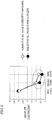
- FIG. 1 shows UCL measurement results of individuals which were measured through subjective reporting in the subjective report experiment.
- FIG. 1 indicates average values of two measurement results each.
- the sound pressure is in units of dBHL.
- FIG. 1 shows UCL measurement results of individuals which were measured through subjective reporting in the subjective report experiment.
- FIG. 1 indicates average values of two measurement results each.
- the sound pressure is in units of dBHL.
- toneburst sounds with a duration of 50 ms.
- Each sound stimulation had a rise (rise) and (fall) of 3 ms each.
- characteristic amount variation in the event-related potential against changing sound pressure was examined by using sound stimulations of the three sound pressures (80, 75, 70dBHL).
- a group of sound stimulations pertaining to the same frequency will be referred to as an "sound stimulation group”.
- the sound stimulations contained in the sound stimulation group were with respect to the same ear at predetermined intervals. Each sound stimulation was presented to one ear through headphones.
- FIG. 2 schematically shows sound stimulations presented in the electroencephalogram measurement experiment.
- the interval between sound stimulations within a sound stimulation group of the same frequency (ISI1 in FIG. 2 ) was fixed at 300 ms.
- the interval between sound stimulation groups (ISI2 in FIG. 2 ) was randomly decided within a range of 450 ⁇ 100 ms.
- the sound stimulation group for the right or left ear and for each different frequency was repeated 30 times (totaling in 180 sound stimulation groups).
- the inventors determined the frequency and the ear for which to present the sound stimulation group under the following constraints.
- FIG. 3(a) shows electrode positions according to the International 10-20 system (10-20 System).
- FIG. 3(b) shows the positions of electrodes worn in this experiment.
- circled numbers 1, 2, and 3 represent electrode positions C3, Cz, and C4, respectively.
- the inventors recorded the electroencephalogram from C3, Cz, and C4 (the International 10-20 system) on the scalp, on the basis of the right mastoid.
- a "mastoid” is a protrusion of the cranium below the hind root of an ear.
- FIG. 3(b) shows the mastoid position as "Ref".
- the sampling frequency was 1000 Hz; the time constant was 0.3 seconds; and an analog low-pass filter was applied at 30 Hz.
- the entire time slot of electroencephalogram data measured off-line was subjected to a 5-20 Hz digital band-pass filter. Thereafter, as an event-related potential in response to a sound stimulation for the right or left ear, for each different frequency, and for each different sound pressure, a waveform from -100 ms to 400 ms was cut out based on the respective sound stimulation as a starting point.
- "-100 ms" means a point in time which is 100 milliseconds before the point in time at which a sound stimulation is presented.
- an electroencephalogram waveform in a range from 0 ms to 300 ms of the event-related potential was subjected to a continuous wavelet transform to derive a wavelet coefficient for each time and each frequency.
- the waveforms and wavelet coefficients of event-related potential were arithmetic-meaned, for each individual person, each of the right or left ear, each frequency, and every sound stimulations of first to third sounds. These will be referred to as, respectively, the arithmetic mean waveform and the arithmetic mean wavelet coefficient. Those trials which exhibited an amplitude in absolute value of 50 ⁇ V or more at any electrode were excluded from the total arithmetic mean and arithmetic mean, because they presumably are under the influence of noises, e.g., eye movements and blinks.
- wavelet characteristic amounts average values of the arithmetic mean wavelet coefficients over a frequency range from 5 Hz to 12.5 Hz were calculated in every time range of 50 ms.
- the subjective UCL value can only be an index that is prone to fluctuations among participants, because of different personalities existing with respect to overbearing sounds. This makes it difficult to identify the presence or absence of a characteristic amount that reflects a subjective UCL value from the data of each individual person. Therefore, in order to reduce such fluctuations, event-related potentials were arithmetic-meaned and compared while making a distinction between large subjective UCL values and small subjective UCL values. Specifically, an arithmetic mean was taken with respect to the cases where the subjective UCL value for each participant and for each frequency was greater than 95dBHL, or the cases where it was equal to or less than 95dBHL, and these results were compared.
- 95dBHL is a value near the center of the subjective UCL values of all participants obtained from the subjective report experiment, and there were substantially the same number of cases where the subjective UCL value was greater than 95dBHL as the cases where it was equal to or less than 95dBHL.
- FIG. 4 shows total arithmetic mean electroencephalogram waveforms for different subjective UCL values.
- Each electroencephalogram waveform subjected to the total was measured at the central portion (Cz), from 100 ms before the first sound in the sound stimulation group until 400 ms after the third sound.
- a thick line indicates the case where the subjective UCL value is greater than 95dBHL, whereas a thin line indicates the case where the subjective UCL value is 95dBHL or less.
- the horizontal axis represents time in units of ms, and the vertical axis represents potential in units of ⁇ V. On the horizontal axis, 0 ms denotes a point at which the first sound is presented.
- a negative N1 component is induced at about 100 ms and a positive P2 component is induced at about 200 ms.
- the N1-P2 amplitude is larger in the case where the subjective UCL value is greater than 95dBHL (indicated by the thick line), than in the case where the subjective UCL value is 95dBHL or less. This suggests an ability to estimate a UCL based on an index which is the difference in event-related potential at the second sound and thereafter.
- an N1-P2 amplitude represents the absolute value of a difference between the negative amplitude of an N1 component and the positive amplitude of a P2 component.
- FIG. 16 shows a relationship between greater or smaller subjective UCL values and the N1-P2 amplitude.
- FIG. 16 shows N1-P2 amplitude in response to the first to third sounds, with respect to the case where the subjective UCL value is greater than 95dBHL and the case where the subjective UCL value is 95dBHL or less.
- the N1-P2 amplitude is defined as the absolute value of a difference between an N1 amplitude and a P2 amplitude.
- the N1 amplitude is a zone average potential from 90 ms to 110 ms after the presentation of each sound stimulation of the first to third sounds.
- the P2 amplitude is a zone average potential from 190 ms to 210 ms after each sound stimulation presentation.
- the N1-P2 amplitude in response to the first to third sounds is 4.24 ⁇ V, 2.51 ⁇ V, 1.45 ⁇ V at 1000 Hz, respectively. Also, the N1-P2 amplitude is 2.99 ⁇ V, 1.45 ⁇ V, and 1.00 ⁇ V at 2000 Hz. Also, the N1-P2 amplitude is 2.28 ⁇ V, 1.40 ⁇ V, and 0.78 ⁇ V at 4000 Hz.
- the N1-P2 amplitude in response to the first to third sounds is 4.24 ⁇ V, 1.95 ⁇ V, 0.99 ⁇ V at 1000 Hz; 2.95 ⁇ V, 1.11 ⁇ V, 0.88 ⁇ V at 2000 Hz; and 1.84 ⁇ V, 1.33 ⁇ V, 0.63 ⁇ V at 4000 Hz.
- the N1-P2 amplitude in response to the second and third sounds is larger in the case where the subjective UCL value is greater than 95dBHL than in the case where the subjective UCL value is 95dBHL or less. This indicates that, depending on the subjective UCL value, the event-related potential for changing sound pressure varies at least in terms of N1-P2 amplitude.
- the inventors examined the relationship between the subjective UCL value and the wavelet characteristic amount. Then, the inventors conducted a discriminant analysis in order to ascertain the accuracy of an uncomfortable sound pressure estimation using changes in this characteristic amount.
- FIG. 5 shows wavelet characteristic amounts in response to the first to third sounds, under different conditions and different subjective UCL values.
- FIG. 5 indicates wavelet characteristic amounts in a time slot from 201 ms to 250 ms, this time slot defining a time zone as reckoned from a point at which each sound stimulation is presented. It can be seen that, although the difference in wavelet characteristic amount is small with respect to the first sound (80dBHL), the wavelet characteristic amounts in response to the second sound (75dBHL) and the third sound (70dBHL) differ depending on the subjective UCL value.
- the wavelet characteristic amount in response to the second and third sounds are larger in the case where the subjective UCL value is greater than 95dBHL, than in the case where the subjective UCL value is 95dBHL or less. This indicates that, depending on the subjective UCL value, the event-related potential for changing sound pressure varies in terms of wavelet characteristic amount.
- FIG. 6 shows an example of data used in an uncomfortable sound pressure estimation.
- Each subjective UCL value shown in FIG. 6 was measured through the subjective report experiment for each participant, each of the right or left ear, and each frequency.
- the columns corresponding to the first to third sounds show wavelet characteristic amounts (at 201 ms to 250 ms after sound stimulation) of the event-related potentials in response to the first to third sounds of a sound stimulation group. These characteristic amounts for each sound stimulation group were trained against the respective subjective UCL value, and a linear discrimination was conducted.
- the inventors conducted the linear discrimination by using target data against training data, the target data for linear discrimination being the characteristic amounts of the event-related potentials for the sound stimulation group taken for a given participant, and the training data having been generated from the characteristic amounts of event-related potentials of other people. Moreover, the inventors generated the training data from the characteristic amounts of the event-related potentials of other people for each condition, each of the right or left ear, and each frequency.
- the training data was generated from the characteristic amounts of the data of the event-related potential for the right ear and 1000 Hz from a participant other than participant 01.
- the characteristic amounts the aforementioned wavelet characteristic amounts (time range 50 ms) were used.
- characteristic amounts were added in extra columns, in either the target data for linear discrimination or the training data. For example, if wavelet characteristic amounts from 151 ms to 200 ms and wavelet characteristic amounts from 201 ms to 250 ms were to be employed in combination, in addition to the first to third columns being allocated to the characteristic amounts in response to the first to third sounds regarding the former, fourth to sixth columns were allocated to the characteristic amounts in response to the first to third sounds regarding the latter.
- An "estimation error” was defined as the absolute value of a difference between a subjective UCL value and a result of uncomfortable sound pressure estimation. Accuracy of estimation was measured on the basis of an average estimation error, which was obtained by averaging the estimation errors of all participants with respect to right and left and all frequencies.
- FIG. 7 shows, as exemplification of linear discrimination results, distributions under different conditions of results of uncomfortable sound pressure estimation based on subjective UCL values and linear discrimination, in the case where five characteristic amounts are used in combination.
- the analysis was conducted for each condition, each of the right or left ear, and each frequency; however, FIG. 7 shows altogether the results obtained for each of the right or left ear and for each frequency.
- the horizontal axis represents subjective UCL values in units of dBHL
- the vertical axis represents uncomfortable sound pressure estimation values in units of dBHL.
- Results of uncomfortable sound pressure estimation with respect to subjective UCL values are indicated by ⁇ symbols as lattice points. The size of any ⁇ symbol reflects the frequency distribution of the particular estimation result. The average estimation error was 5.2dB. From these results, it can be seen that uncomfortable sound pressures which are correlated with the subjective UCL values have successfully been estimated, although there are some fluctuations.
- a discriminant analysis may be made not only with wavelet characteristic amounts, but also with P1-N1 amplitude or N1-P2 amplitude information.
- training data may be generated irrespective of the right or left ear and irrespective of frequency.
- an uncomfortable sound pressure estimation system will be described in outline first. Thereafter, the construction and operation of an uncomfortable sound pressure estimation system including the uncomfortable sound pressure estimation apparatus will be described.
- An uncomfortable sound pressure estimation system presents pure tones of the same frequency three times in succession at monotonously descending sound pressures, in a sound pressure range higher than the HTL and lower than a sound pressure which is generally evaluated to be the UCL, extracts electroencephalographic characteristic amounts in response to the respective sound stimulations of the first to third sounds, and measures an uncomfortable sound pressure from a change pattern of the characteristic amounts.
- an electroencephalogram is measured as a potential difference between the probe electrode and the reference electrode.
- the level and polarity of a characteristic component of the event-related potential may possibly vary depending on the sites at which electrodes for electroencephalogram measurement are worn, and on the positions at which the reference electrode and the probe electrode are set.
- those skilled in the art should be able to extract a characteristic feature of the event-related potential and perform an uncomfortable sound pressure measurement by making appropriate modifications in accordance with the particular reference electrode and probe electrode used. Such variants are encompassed within the present disclosure.
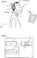
- FIG. 8 shows a construction and an environment of use for an uncomfortable sound pressure estimation system 100 according to the present embodiment.
- the uncomfortable sound pressure estimation system 100 (hereinafter referred to as the "estimation system 100 ”) corresponds to the system construction of Embodiment 1 described later and shown in FIG. 10 .
- the estimation system 100 includes an uncomfortable sound pressure estimation apparatus 1, a sound stimulation output section 10, a biological signal measurement section 50, and an HTL input section 90.
- the sound stimulation output section 10 is headphones or loudspeakers for outputting a sound stimulation to the user 5, for example.
- the biological signal measurement section 50 is a measuring instrument which measures a biological signal of the user.
- the biological signal measurement section 50 may be an electroencephalograph.
- the biological signal measurement section 50 is connected to at least two electrodes A and B.
- electrode A is attached to a mastoid of the user 5, whereas electrode B is attached to a central portion (so-called Cz) on the scalp of the user 5.
- the biological signal measurement section 50 measures an electroencephalogram of the user 5 that corresponds to a potential difference between electrode A and electrode B, and outputs an electroencephalogram signal.
- the HTL input section 90 is an input device which accepts an HTL value of each user, which is measured in advance.
- the HTL input section 90 receives an input of an HTL value for the right or left and for each frequency from the user or an evaluator.
- the input HTL value is sent to the uncomfortable sound pressure estimation apparatus 1.
- FIG. 8 shows an example where the HTL input section 90 is provided separately from the uncomfortable sound pressure estimation apparatus 1.
- the HTL input section 90 may be e.g. a tablet terminal, so long as it is capable of accepting an HTL value input. In that case, it is connected in a wired or wireless manner to the uncomfortable sound pressure estimation apparatus 1 to perform exchange of the input HTL value. Moreover, the HTL input section 90 may be provided within a pair of headphones in which the uncomfortable sound pressure estimation apparatus 1 is incorporated.
- the estimation system 100 determines a sound stimulation group (a first sound to a third sound) of a certain frequency, at monotonously descending sound pressures. Then, as characteristic amounts, the estimation system 100 extracts wavelet coefficients of the electroencephalogram (event-related potential) of the user 5 measured based on the points of presenting the first sound to the third sound as starting points. Then, from a change pattern of the characteristic amounts in response to the first sound to the third sound, the estimation system 100 estimates an uncomfortable sound pressure for that user. The details of the respective component elements and processes will be described later.
- the biological signal measurement section 50 and the sound stimulation output section 10 are provided in the housing of the uncomfortable sound pressure estimation apparatus 1 (hereinafter referred to as the "estimation apparatus 1" ) shown in FIG. 8 .
- the biological signal measurement section 50 and the sound stimulation output section 10 of the uncomfortable sound pressure estimation apparatus 1 may be provided in a separate housing. In that case, an electroencephalogram signal measured by the biological signal measurement section 50 is sent to the uncomfortable sound pressure estimation apparatus 1, which is connected in a wireless or wired manner.
- the uncomfortable sound pressure estimation apparatus 1 determines the right or left ear, frequency, sound pressure, and timing for the sound stimulations for uncomfortable sound pressure estimation. Generating the determined sound stimulations, the sound stimulation output section 10 presents the sound stimulations determined by the uncomfortable sound pressure estimation apparatus 1 to the user 5.
- FIG. 9 shows the hardware construction of the uncomfortable sound pressure estimation apparatus 1 according to the present embodiment.
- the uncomfortable sound pressure estimation apparatus 1 includes a CPU 30, a memory 31, and an audio controller 32.
- the CPU 30, the memory 31, and the audio controller 32, are interconnected via a bus 34, so that data exchange among them is possible.
- the CPU 30 executes a computer program 35 which is stored in the memory 31.
- a processing procedure as illustrated by a subsequently-described flowchart is described in the computer program 35.
- the uncomfortable sound pressure estimation apparatus 1 performs processes of controlling the entire estimation system 100, such as generation of sound stimulations, extraction of characteristic amounts of event-related potentials, and discriminant analysis for uncomfortable sound pressure determination. These processes will be described in detail later.
- the audio controller 32 outputs the sound stimulations for presentation via the sound stimulation output section 10 at designated sound pressures.
- the uncomfortable sound pressure estimation apparatus 1 may be implemented as a piece of hardware (e.g., a DSP) consisting of a semiconductor circuit having a computer program incorporated therein.
- a DSP can realize all functions of the aforementioned CPU 30, memory 31, and audio controller 32 on a single integrated circuit.
- the aforementioned computer program 35 may be distributed on the market in the form of a product recorded on a storage medium such as a CD-ROM, or transmitted through telecommunication lines such as the Internet.
- a device having the hardware shown in FIG. 9 e.g., a PC
- FIG. 9 e.g., a PC
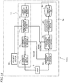
- FIG. 10 shows the functional block construction of the estimation system 100 according to the present embodiment.
- the estimation system 100 includes the sound stimulation output section 10, the biological signal measurement section 50, the HTL input section 90, and the uncomfortable sound pressure estimation apparatus 1.
- the component elements of the estimation system 100 are connected in a wired or wireless manner.
- the estimation apparatus 1 is connected to the sound stimulation output section 10 and the biological signal measurement section 50 in a wired or wireless manner.
- the user 5 block is illustrated for ease of explanation.
- the uncomfortable sound pressure estimation apparatus 1 includes an event-related potential characteristic amount extraction section 55, an uncomfortable sound pressure determination section 65, a sound stimulation group determination section 70, a sound stimulation sound pressure determination section 71, a sound stimulation generation section 75, and a result accumulating DB 80.
- the event-related potential characteristic amount extraction section will be referred to as the “extraction section”
- the uncomfortable sound pressure determination section as the “determination section”
- the sound stimulation sound pressure determination section as the "sound pressure determination section”.
- the uncomfortable sound pressure estimation apparatus 1 does not include the sound stimulation output section 10.
- this construction is an example.
- an uncomfortable sound pressure estimation apparatus 1 which at least includes the sound stimulation output section 10, the extraction section 55, and the determination section 65 may be provided. These component elements can be accommodated in a single housing to be operated as a single uncomfortable sound pressure estimation apparatus.
- the respective functional blocks of the uncomfortable sound pressure estimation apparatus 1 correspond to functions which are realized by the CPU 30, the memory 31, and the audio controller 32 as a whole upon executing the program which has been described in conjunction with FIG. 9 .
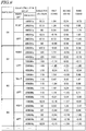
- the HTL input section 90 accepts input of an HTL value for each of the right or left ear and for each frequency of the user. Examples of HTL values to be input to the HTL input section 90 are shown in FIG. 11. FIG. 11 shows HTL values from 250 Hz to 4000 Hz for each of the right or left ear, as measured by an audiometer. The HTL values may be in units of dBHL, thus conforming to the audiometer, for example.
- the HTL input section 90 sends the input HTL value to the estimation apparatus 1. In the case where measurement is to be taken for only one ear, the HTL input section 90 may accept input of data for only either HTL value, and send it.
- the sound stimulation group determination section 70 determines information of a plurality of sound stimulations to be presented to the user 5.
- the information of the sound stimulation group contains the ear to which the sound stimulations are to be presented (the right ear or the left ear), the frequencies of the sound stimulations to be presented, the duration of the sound stimulations within the sound stimulation group, and the interval between the plurality of sound stimulations.
- the sound stimulation group determination section 70 may randomly decide the frequency and the ear for which to present the sound stimulation under the following constraints, for example.
- the duration of a sound stimulation may be set to e.g. 25 ms or more, so that an auditory evoked potential will be stable induced.
- the interval between stimulations is set to a time which is equal to or greater than the duration of a sound stimulation but equal to or less than 1 second. For example, it may be 300 ms, or 200 ms.
- the sound pressure determination section 71 receives the information of the ear to which the sound stimulation group is presented (the right ear or the left ear), frequency, duration of each sound stimulation in the sound stimulation group, and interval between stimulations. Moreover, from the HTL input section 90, the sound pressure determination section 71 receives the HTL value information for each of the right or left ear and for each frequency.
- the first sound, the second sound, and the third sound at least has the same frequency. It is meant that "same frequency" is inclusive of sounds having a difference in frequency that is smaller than humans can aurally distinguish. In the present specification, a difference of 5 Hz or less, for example, is regarded as pertaining to the same frequency.
- the sound pressure determination section 71 determines the sound pressures of the first sound to the third sound in the sound stimulation group within a sound pressure range which is higher than the HTL value received from the HTL input section 90 and lower than a predetermined threshold value.
- the values of sound pressure of the first sound to the third sound are determined so that their sound pressures decrease consecutively.
- the "predetermined threshold value” is a sound pressure which is generally evaluated to be the UCL, for example. In other words, the sound pressures of the first sound to the third sound are to be determined within a sound pressure range which permits comfortable hearing by the user 5.
- the sound pressure determination section 71 retains the predetermined threshold value in advance.
- the sound pressure determination section 71 may determine the sound pressure of the first sound to be 80dBHL, the sound pressure of the second sound to be 75dBHL, and the sound pressure of the third sound to be 70dBHL.
- the sound pressure determination section 71 may be arranged so as to never determine the sound pressure to be greater than the predetermined threshold value. For example, it may be prearranged that the range sound of pressure that can be chosen by the sound pressure determination section 71 is equal to or less than the predetermined threshold value.
- the sound stimulation generation section 75 Based on the information of the ear to which the sound stimulation group is presented, frequency, duration of each sound stimulation in the sound stimulation group, interval between stimulations, and sound pressure which is received from the sound pressure determination section 71, the sound stimulation generation section 75 generates sound stimulation data or audio signals.
- Each sound stimulation may be a tone burst sound with a rise and fall of 3 ms, for example.
- the sound stimulation generation section 75 sends the sound stimulation group to the sound stimulation output section 10 with a predetermined interval between stimulations, and outputs sound stimulations to the user via the sound stimulation output section 10. At this timing, the sound stimulation generation section 75 outputs a trigger signal(s) to the biological signal measurement section 50. Note that, without outputting any trigger signal, the sound stimulation generation section 75 may only send the generated sound stimulation data to the sound stimulation output section 10.
- the sound stimulation data may be generated in such a manner that a single piece of sound stimulation data is created for one sound stimulation group, from which a plurality of sound stimulations that undergo changes in sound pressure at a predetermined time interval are derived, for example.
- the trigger signal to be sent to the biological signal measurement section 50 may only be sent at the timing of presenting the first sound.
- the sound stimulation generation section 75 may be composed of an input section. Information which is input via the input section by the user 5 or a person who tests the hearing of the user 5 may be utilized as the auditory stimulation information. In other words, in the estimation system 200, auditory stimulations may be externally received, rather than being internally generated.
- the sound stimulation output section 10 is connected to the sound stimulation generation section 75 in a wired or wireless manner.
- the sound stimulation output section 10 reproduces sound stimulation data which is generated by the sound stimulation generation section 75, and presents it to the user 5.
- the sound stimulation output section 10 correctly outputs the sound stimulation generated by the sound stimulation generation section 75 to each of the right or left ear.
- it may be headphones whose frequency characteristics are free of distortion.
- the sound stimulation output section 10 will also be referred to as the output section. With the sound stimulation to the user 5 as a trigger, the sound stimulation output section 10 may send information of the point at which the sound stimulation was presented, to the extraction section 55.
- the biological signal measurement section 50 measures a biological signal of the user 5.
- the user 5 is at least wearing a probe electrode and a reference electrode.
- the biological signal measurement section 50 measures an electroencephalogram signal which corresponds to a potential difference between the probe electrode and the reference electrode. Frequency filtering with an appropriate cutoff frequency may be applied to the electroencephalogram signal. Then, an event-related potential may be cut out from the electroencephalogram signal which has been subjected to frequency filtering.
- the biological signal measurement section 50 sends the measured electroencephalogram or filtered electroencephalogram signal to the extraction section 55.
- the measured electroencephalogram signal or filtered electroencephalogram signal may also be referred to as electroencephalogram data.
- the biological signal measurement section 50 applies frequency filtering with an appropriate cutoff frequency to the electroencephalogram data, and based on the trigger received from the sound stimulation generation section 75 as a starting point, cuts out an event-related potential in a predetermined zone (e.g., a zone from 100 ms before the presentation of the first sound to 400 ms after the presentation of the third sound), and sends that waveform data to the extraction section 55.
- a predetermined zone e.g., a zone from 100 ms before the presentation of the first sound to 400 ms after the presentation of the third sound
- An event-related potential is a fluctuation in the potential of an electroencephalogram that occurs in response to a stimulation.
- the event-related potential comes in different event-related potential types, depending on: (1) the polarity of potential (plus or minus); (2) the latency (the time from occurrence of a stimulation and until occurrence of a potential fluctuation); (3) the amplitude level of potential; and so on.
- Each different type of signal contains different information concerning the user 5.
- the cutoff frequency may be set so as to pass e.g. 5 Hz to 15 Hz. It is assumed that the user 5 has worn the electroencephalograph in advance.
- the probe electrode for electroencephalogram measurement is attached at the central portion Cz, for example.
- the extraction section 55 acquires waveform data of the event-related potential received from the biological signal measurement section 50, and calculates wavelet-coefficient related characteristic amounts in response to the first sound to the third sound.
- the extraction section 55 sends the calculated characteristic amounts and the sound stimulation information (right or left ear, frequency, sound pressure, etc.) to the determination section 65.
- Each wavelet-coefficient related characteristic amount may be derived as an average value of wavelet coefficients over a predetermined range on each of the frequency axis and the time axis, for example. For instance, an average may be taken over a range from 5 Hz to 15 Hz on the frequency axis and over a time range of 50 ms on the time axis.
- a biological signal in a time range of 300 ms or less after an auditory stimulation from the point of auditory stimulation may be used. So long as uncomfortable sound pressure estimation is possible, the ranges on the frequency axis and the time axis over which averaging is to be conducted for characteristic amount calculation may be finer or coarser than 5 Hz to 15 Hz and every 50 ms.
- an N1 component of event-related potential for characteristic amount calculation for example, a negative-component biological signal in a time range of 50 ms to 150 ms after presentation of an auditory stimulation may be used.
- a P2-component of the event-related potential for characteristic amount calculation may be a positive-component biological signal in a time range of 150 ms to 250 ms after an auditory stimulation.
- the determination section 65 refers to the characteristic amounts of the respective sound stimulations of the first sound, second sound, and third sound as extracted by the extraction section 55 (e.g., wavelet coefficients), as well as a predetermined criterion which previously defines association between characteristic amounts and uncomfortable sound pressure values, and determines an uncomfortable sound pressure of the user 5.
- the determination section 65 determines an uncomfortable sound pressure in view of the characteristic amounts for the respective sound stimulations (e.g., wavelet-coefficient related characteristic amounts for the respective ones of the first sound to the third sound) received from the extraction section 55.
- the determination section 65 conducts linear discrimination by using a predetermined criterion and wavelet characteristic amounts prepared in advance.
- the "predetermined criterion” means information which previously defines association between characteristic amounts and uncomfortable sound pressure values.
- the "predetermined criterion” may be a table which previously defines association between wavelet characteristic amounts and uncomfortable sound pressure values, or a predetermined formula (mathematical function), for example.
- the determination section 65 retains the predetermined criterion in advance.
- the aforementioned "predetermined criterion" is training data for subjective UCL values, for example.
- the training data can be generated from subjective UCL values and wavelet characteristic amounts that are measured by previously conducting the aforementioned subjective report experiment and electroencephalogram measurement experiment for at least two or more other people.
- the sound stimulation conditions concerning the sound pressure and number of sound stimulations in the electroencephalogram measurement experiment when generating the training data need to identically conform to the pattern of changing stimulation sound pressure as determined by the sound pressure determination section 71, in the case where successive sounds are presented as the sound stimulations.
- the training data may be retained so as to be itemized for each of the right or left ear and for each frequency, as shown in FIG. 6 , for example.
- the training data which is utilized for uncomfortable sound pressure estimation may be switched so that the right or left ear and frequency of the training data match the right or left ear and frequency of the one who is the subject of determination.
- the training data may be switched according to the user's symptoms of hypacusia. For example, training data may be prepared and switched between general categories, e.g., conductive deafness and perceptive deafness. Also, training data may be prepared and switched according to the audiogram pattern, e.g., gradual low tone loss or gradual high tone loss.
- the determination section 65 sends the determined uncomfortable sound pressure to the result accumulating database (DB) 80.
- DB result accumulating database
- the result accumulating DB 80 stores the uncomfortable sound pressure received from the determination section 65 in association with the right or left ear and each frequency as indicated by the sound stimulation group information received from the sound stimulation group determination section 70.
- FIG. 12 shows an example of data accumulation in the result accumulating DB 80.
- FIG. 12 illustrates a case where an uncomfortable sound pressure is accumulated with respect to each of the right or left ear and each different frequency.
- FIG. 12 illustrates uncomfortable sound pressures corresponding to three frequencies, this is an example. As shown in FIG. 11 , uncomfortable sound pressures corresponding to 250 Hz and 500 Hz may be included.
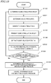
- FIG. 13 is a flowchart showing a procedure of processing performed in the estimation system 100.
- the HTL input section 90 accepts input of the user's HTL value for each of the right or left ear and for each frequency, and sends that information to the sound pressure determination section 71.
- the sound stimulation group determination section 70 determines the ear to which the sound stimulation group is presented, frequency, duration of each sound stimulation in the sound stimulation group, and interval between stimulations.
- the frequency and the ear for which to present the sound stimulation may be randomly decided under the following constraints, for example.
- the duration of a sound stimulation is set to be e.g. 25 ms or more, so that an auditory evoked potential is stably induced.
- the interval between stimulations is set to a time which is equal to or greater than the duration of the sound stimulation but equal to or less than 1 second. For example, it may be 300 ms, or 200 ms.
- the sound stimulation group determination section 70 sends the determined information of the ear to which the sound stimulation group is presented, frequency, duration of each sound stimulation in the sound stimulation group, and interval between stimulations.
- the sound pressure determination section 71 receives the information of the ear to which the sound stimulation group is presented, frequency, duration of each sound stimulation in the sound stimulation group, and interval between stimulations. Moreover, from the HTL input section 90, the sound pressure determination section 71 receives the user's HTL value for each of the right or left ear and for each frequency. Then, the sound pressure determination section 71 determines the sound pressures of the first sound to the third sound in the sound stimulation group so as to constitute monotonously descending sound pressures in a sound pressure range higher than the HTL and lower than a sound pressure which is generally evaluated to be the UCL.
- the sound pressure of the first sound may be determined to be 80dBHL, the sound pressure of the second sound to be 75dBHL, and the sound pressure of the third sound to be 70dBHL.
- the sound pressure of the first sound may be determined to be 80dBHL, the sound pressure of the second sound to be 70dBHL, and the sound pressure of the third sound to be 60dBHL.
- the sound pressure determination section 71 sends the determined sound pressure information for each sound stimulation in the sound stimulation group to the sound stimulation generation section 75.
- the sound stimulation generation section 75 Based on the sound stimulation information received from the sound pressure determination section 71, the sound stimulation generation section 75 generates sound stimulation data.
- Each sound stimulation may be a tone burst sound with a rise and fall of 3 ms, for example.
- the sound stimulation generation section 75 presents the sound stimulation group to the user via the sound stimulation output section 10, and at that timing outputs a trigger signal to the biological signal measurement section 50.
- the sound stimulation data may be generated in such a manner that a single piece of sound stimulation data is created for one sound stimulation group, from which a plurality of sound stimulations that undergo changes in sound pressure at a predetermined time interval are derived, for example.
- the trigger signal to be sent to the biological signal measurement section 50 may only be sent at the timing of presenting the first sound.
- the biological signal measurement section 50 measures an electroencephalogram as a biological signal. Then, it applies frequency filtering with an appropriate cutoff frequency to the electroencephalogram data, and based on the trigger received from the sound stimulation generation section 75 as a starting point, cuts out an event-related potential in a predetermined zone (e.g., a zone from 100 ms before the presentation of the first sound to 400 ms after the presentation of the n th sound), and sends the waveform data of this event-related potential to the extraction section 55.
- a predetermined zone e.g., a zone from 100 ms before the presentation of the first sound to 400 ms after the presentation of the n th sound
- the extraction section 55 extracts wavelet-coefficient related characteristic amounts in response to the first sound to the third sound, in accordance with the particulars of the sound stimulations received from the sound pressure determination section 71.
- the extraction section 55 is able to calculate wavelet coefficients from this single piece of event-related potential data. From the calculated wavelet coefficients, the extraction section 55 is able to extract the respective wavelet-coefficient related characteristic amounts in response to the first sound to the third sound based on time and frequency. The extracted wavelet-coefficient related characteristic amounts in response to the first sound to the third sound are accumulated in a storage device such as a memory (not shown).
- the present embodiment illustrates that the wavelet-coefficient related characteristic amounts in response to the first sound to the third sound are each extracted, this is an example. Extraction of the characteristic amount in response to the first sound may be omitted. As shown in FIG. 5 , the wavelet coefficients for the second sound and the third sound reflect the difference in subjective UCL value. Therefore, in uncomfortable sound pressure determination, it suffices if the wavelet coefficient (s) for the second sound and/or third sound is available.
- the sound stimulation group determination section 70 determines whether the number of times of presentation of the sound stimulation group has reached a predetermined number of times.
- the predetermined number of times may be 20 times, for example. Note that "20 times" is a mere example, although it is a number of summations which is frequently adopted in fields where event-related potentials are to be measured.
- step S109 If the number of times of presentation is equal to or less than the predetermined number of times, the process returns to step S102 to repeat the processes of step S102 and after. If the number of times of presentation is equal to or greater than the predetermined number of times, the process proceeds to step S109.
- the extraction section 55 takes an arithmetic mean of the wavelet-coefficient related characteristic amounts in response to the first sound to the third sound which have been accumulated in the storage device through the predetermined number or more trials, based on the sound stimulation information received from the sound pressure determination section 71.
- the arithmetic mean is taken for each of the first sound, the second sound, or the third sound, and for each of these, taken for each of the right or left ear and for each frequency.
- the extraction section 55 sends the arithmetic-meaned wavelet-coefficient related characteristic amounts to the determination section 65, and the process proceeds to step S110.
- the determination section 65 determines an uncomfortable sound pressure by using the respective wavelet-coefficient related characteristic amounts in response to the first sound to the third sound received from the extraction section 55.
- the uncomfortable sound pressure determination is achieved through linear discrimination, by using the wavelet characteristic amounts of other people and training data for subjective UCL values that are previously prepared.
- the training data which is utilized for uncomfortable sound pressure estimation may be switched so that the right or left ear and frequency of the training data match the right or left ear and frequency of the one who is the subject of determination.
- the training data may be switched according to the user's symptoms of hypacusia.
- training data may be prepared and switched between general categories, e.g., conductive deafness and perceptive deafness.
- training data may be prepared and switched according to the audiogram pattern, e.g., gradual low tone loss or gradual high tone loss.
- the result accumulating DB 80 accumulates the information of a result of uncomfortable sound pressure determination that is received from the determination section 65 for each of the right or left ear and for each frequency of the sound stimulation group presented at step S105.
- the estimation system 100 of the present embodiment presents pure tones of the same frequency three times in succession at monotonously ascending or monotonously descending sound pressures, extracts electroencephalographic characteristic amounts in response to the respective sound stimulations of the first to third sounds, and measures an uncomfortable sound pressure from a change pattern of the characteristic amounts. This realizes a hearing aid fitting which does not allow the user to experience an uncomfortable sound pressure upon wearing a hearing aid.
- the biological signal measurement section 50 cuts out an event-related potential in a predetermined range based on a trigger from the sound stimulation generation section 75 as a starting point, and sends it to the extraction section 55.
- this process is an example.
- the biological signal measurement section 50 may constantly measure an electroencephalogram, and the extraction section 55 may perform cutting out of an event-related potential and a baseline correction as needed.
- the sound stimulation generation section 75 does not need to send a trigger to the biological signal measurement section 50, but may only send a trigger to the extraction section 55.
- each result of determination of the determination section 65 may simply be output.
- Each result of determination can be utilized as information concerning uncomfortable sound pressure.
- FIG. 14 shows an example of an uncomfortable sound pressure estimation system 100a which includes an uncomfortable sound pressure estimation apparatus 1a and a sound stimulation apparatus 11.
- the uncomfortable sound pressure estimation apparatus 1a is a version of the uncomfortable sound pressure estimation apparatus 1 ( FIG. 10 ) from which the sound stimulation group determination section 70, the sound pressure determination section 71, and the sound stimulation generation section 75 are omitted.
- the sound stimulation apparatus 11 includes the sound stimulation group determination section 70, the sound pressure determination section 71, the sound stimulation generation section 75, and the sound stimulation output section 10 shown in FIG. 10 .
- the sound stimulation apparatus 11 and the uncomfortable sound pressure estimation apparatus 1a are connected to the uncomfortable sound pressure estimation apparatus 1 in a wired or wireless manner to perform exchange of information.
- FIG. 17 shows the functional block construction of an uncomfortable sound pressure measurement system 200 according to the present embodiment.
- the uncomfortable sound pressure estimation system 200 (hereinafter referred to as the "estimation system 200 ") includes a sound stimulation output section 10, a biological signal measurement section 50, and an uncomfortable sound pressure estimation apparatus 2. Blocks which are identical to those in FIG. 10 showing the construction of Embodiment 1 will be denoted by like numerals, and their description will be omitted. Note that the hardware construction of the uncomfortable sound pressure estimation apparatus 2 is as shown in FIG. 9 . As a program which defines different processes from the program 35 described in Embodiment 1 is executed, the uncomfortable sound pressure estimation apparatus 2 of the present embodiment as shown in FIG. 17 is realized.
- the uncomfortable sound pressure estimation apparatus 2 of the present embodiment differs from the uncomfortable sound pressure estimation apparatus 1 of Embodiment 1 in that an uncomfortable sound pressure determination section 66 (hereinafter the "determination section 66 ") is provided, instead of the determination section 65.
- the names of the component element of the uncomfortable sound pressure estimation apparatus 2 are primarily identical to those of the uncomfortable sound pressure estimation apparatus 1 of Embodiment 1, reference numerals are used where any different operation and/or function is possessed.
- the event-related potential characteristic amount extraction section 56 (hereinafter the “extraction section 56 ") and the sound stimulation sound pressure determination section 72 (hereinafter the “sound pressure determination section 72 ”) according to the present embodiment differ from the extraction section 55 and the sound pressure determination section 71 of Embodiment 1 in terms of operation and/or function.
- FIG. 17 illustrates that the uncomfortable sound pressure estimation apparatus 2 does not include the sound stimulation output section 10, this construction is an example.
- an uncomfortable sound pressure estimation apparatus 2 which at least includes the sound stimulation output section 10, the extraction section 56, and the determination section 66 may be provided.
- the sound pressure determination section 72 receives the information of the ear to which the sound stimulation group is presented (the right ear or the left ear), frequency, duration of each sound stimulation in the sound stimulation group, and interval between stimulations. Then, it determines the sound pressures of the first sound to the third sound in the sound stimulation group so as to constitute monotonously descending sound pressures in a sound pressure range lower than a sound pressure which is generally evaluated to be the UCL.
- the sound pressure of the first sound may be determined to be 80dBHL, the sound pressure of the second sound to be 75dBHL, and the sound pressure of the third sound to be 70dBHL.
- the extraction section 56 calculates N1-P2-amplitude related characteristic amounts in response to the second sound and the third sound, in accordance with the particulars of the sound stimulations received from the sound pressure determination section 71.
- the N1-P2 amplitude is determined as the absolute value of a difference between an N1 amplitude and a P2 amplitude.
- the N1 amplitude may be a zone average potential from 90 ms to 110 ms after presenting each of the sound stimulations of the first sound to the third sound, or a peak amplitude.
- the P2 amplitude may similarly be a zone average potential from 190 ms to 210 ms after sound stimulation presentation, or a peak amplitude. Then, the calculated characteristic amounts and the sound stimulation information (right or left ear, frequency, sound pressure, etc.) are sent to the determination section 66.
- the determination section 66 makes a coarse uncomfortable sound pressure determination (high/low). Specifically, a threshold value is provided for each frequency and each of the second sound/third sound, and, if the measured N1-P2 amplitude of the second sound/third sound is greater than the threshold value(s), the uncomfortable sound pressure is determined to be high; and if it is smaller than the threshold value (s), the uncomfortable sound pressure is determined to be low.
- the uncomfortable sound pressure may be determined to be high when both of the N1-P2 amplitudes in response to the second sound and the third sound are greater than the threshold values; or the uncomfortable sound pressure may be determined to be high when either amplitude is greater than the threshold value.
- Examples of threshold values for different frequencies and each of the second sound/third sound are shown in FIG. 18 .
- FIG. 18 indicates an average value, between the case where the subjective UCL value shown in FIG. 16 is greater than 95dBHL and the case where it is equal to or less than 95dBHL, of N1-P2 amplitude for each frequency.
- FIG. 19 is a flowchart showing a procedure of processing by the estimation system 200 of the present embodiment.
- steps of conducting identical processes to the processes of the estimation system 100 FIG. 13 ) will be denoted by like reference numerals, and their description will be omitted.
- the processing by the estimation system 200 of the present embodiment differs from the processing by the uncomfortable sound pressure measurement system 100 of Embodiment 1 with respect to steps S201, S202, and S203. Steps S201 to step S203 will be described below.
- the presented-speech sound determination section 75 receives the information of the ear to which the sound stimulation group is presented (the right ear or the left ear), frequency, duration of each sound stimulation in the sound stimulation group, and interval between stimulations from the sound stimulation group determination section 70. Then, it determines the sound pressures of the first sound to the third sound in the sound stimulation group so as to constitute monotonously descending sound pressures in a sound pressure range lower than a sound pressure which is generally evaluated to be the UCL.
- the sound pressure of the first sound may be determined to be 80dBHL, the sound pressure of the second sound to be 75dBHL, and the sound pressure of the third sound to be 70dBHL.
- the extraction section 56 calculates N1-P2-amplitude related characteristic amounts in response to the second sound and the third sound, in accordance with the particulars of the sound stimulations received from the sound pressure determination section 71.
- the N1-P2 amplitude is determined as the absolute value of a difference between an N1 amplitude and a P2 amplitude.
- the N1 amplitude may be a zone average potential from 90 ms to 110 ms after presenting each of the sound stimulations of the first sound to the third sound, or a peak amplitude.
- the P2 amplitude may similarly be a zone average potential from 190 ms to 210 ms after sound stimulation presentation, or a peak amplitude. Then, the calculated characteristic amounts and the sound stimulation information (right or left ear, frequency, sound pressure, etc.) are sent to the determination section 66.
- the determination section 66 makes a coarse uncomfortable sound pressure determination (high/low). Specifically, a threshold value is provided for each frequency and each of the second sound/third sound, and, if the measured N1-P2 amplitude of the second sound/third sound is greater than the threshold value(s), the uncomfortable sound pressure is determined to be high; and if it is smaller than the threshold value(s), the uncomfortable sound pressure is determined to be low.
- the uncomfortable sound pressure being high would mean that the user has tolerance against sounds of high sound pressure, and the uncomfortable sound pressure being low would mean that he or she lacks tolerance against sounds of high sound pressure.
- sound stimulations of sound pressures that are lower than a sound pressure which is generally evaluated to be the UCL are presented a plurality of times in succession at monotonously descending sound pressures, and based on N1-P2 amplitudes in response to the second sound and the third sound, a simple determination can be made as to whether the user has tolerance against sounds of high sound pressure or not. This would make it possible to automatically reduce the sound volume of a hearing aid or audio player if there is no tolerance against sounds of high sound pressure.
- the uncomfortable sound pressure estimation apparatuses may each be implemented as a semiconductor chip circuit. Instead of a semiconductor chip circuit, it may be implemented as a CPU which is provided within a PC. By executing a computer program, the CPU is able to realize the function of each component element described below.
- an uncomfortable sound pressure of a user can be estimated without presenting any overbearing sound stimulations, which is useful for adjustment of a hearing aid at a hearing aid shop or in households, etc.
- an uncomfortable sound pressure for a person with normal hearing it is also applicable to the setting of a maximum sound volume in an audio device such as a television set or a stereo set, and so on.
Landscapes
- Health & Medical Sciences (AREA)
- Life Sciences & Earth Sciences (AREA)
- Engineering & Computer Science (AREA)
- Physics & Mathematics (AREA)
- Artificial Intelligence (AREA)
- General Health & Medical Sciences (AREA)
- Public Health (AREA)
- Molecular Biology (AREA)
- Veterinary Medicine (AREA)
- Animal Behavior & Ethology (AREA)
- Surgery (AREA)
- Medical Informatics (AREA)
- Biophysics (AREA)
- Pathology (AREA)
- Biomedical Technology (AREA)
- Heart & Thoracic Surgery (AREA)
- Psychiatry (AREA)
- Signal Processing (AREA)
- Physiology (AREA)
- Computer Vision & Pattern Recognition (AREA)
- Audiology, Speech & Language Pathology (AREA)
- Acoustics & Sound (AREA)
- Otolaryngology (AREA)
- Fuzzy Systems (AREA)
- Evolutionary Computation (AREA)
- Mathematical Physics (AREA)
- Multimedia (AREA)
- Psychology (AREA)
- Measurement And Recording Of Electrical Phenomena And Electrical Characteristics Of The Living Body (AREA)
- Measurement Of The Respiration, Hearing Ability, Form, And Blood Characteristics Of Living Organisms (AREA)
Claims (16)
- System zum Schätzen eines unangenehmen Schalldrucks für einen Benutzer (5), umfassend:einen Schallstimulation-Ausgabeabschnitt (10) zum Präsentieren einer Schallstimulationsgruppe für den Benutzer (5), wobei die Schallstimulationsgruppe einen ersten Schall, einen zweiten Schall und einen dritten Schall umfasst, die jeweils reine Töne der gleichen Frequenz sind, undeinen Extraktionsabschnitt (55, 56) zum Extrahieren, aus einem Elektroenzephalogrammsignal des Benutzers (5), einer charakteristischen Größe eines Ereignis-bezogenen Potentials des Elektroenzephalogrammsignals,gekennzeichnet durch:einen Schalldruck-Bestimmungsabschnitt (71, 72), der ausgebildet ist zum Bestimmen der Schalldrücke der Schallstimulationsgruppe als Schalldrücke, die niedriger als ein zuvor vorgesehener unangenehmer Schalldruck sind, wobei der erste Schall, der zweite Schall und der dritte Schall jeweils einen niedrigeren Schalldruck innerhalb eines vorbestimmten Bereichs aufweisen, undeinen Bestimmungsabschnitt (65, 66) zum Bestimmen eines unangenehmen Schalldrucks für den Benutzer (5) bei der Frequenz der Schallstimulationsgruppe basierend auf der durch den Extraktionsabschnitt (55, 56) extrahierten charakteristischen Größe,wobei der Extraktionsabschnitt (55, 56) ausgebildet ist zum Extrahieren einer N1-P2-Amplitude, die auf eine Wavelet-Koeffizient-bezogene charakteristische Größe eines Ereignis-bezogenen Potentials aus dem Elektroenzephalogrammsignal in einer vorbestimmten Zone bezogen ist, die basierend auf einem Punkt für das Präsentieren des zweiten Schalls und/oder des dritten Schalls als eines Startpunkts definiert ist.
- System zum Schätzen eines unangenehmen Schalldrucks nach Anspruch 1, wobei der Bestimmungsabschnitt (65, 66) den unangenehmen Schalldruck unter Bezugnahme auf ein vorbestimmtes Kriterium bestimmt, das zuvor eine Assoziation zwischen charakteristischen Größen und unangenehmen Schalldruckwerten definiert.
- System zum Schätzen eines unangenehmen Schalldrucks nach Anspruch 1, das weiterhin umfasst:einen Schallstimulationsgruppe-Bestimmungsabschnitt (70) zum Bestimmen der Frequenz der Schallstimulationsgruppe,wobei der Schallstimulation-Ausgabeabschnitt (10) den ersten Schall, den zweiten Schall und den dritten Schall mit der durch den Schallstimulationsgruppe-Bestimmungsabschnitt (70) bestimmten Frequenz und mit den durch den Schalldruck-Bestimmungsabschnitt (71, 72) bestimmten Schalldrücken ausgibt.
- System zum Schätzen eines unangenehmen Schalldrucks nach Anspruch 2, wobei der Schalldruck-Bestimmungsabschnitt (71, 72) die Schalldrücke der Schallstimulationsgruppe als Schalldrücke bestimmt, die höher als ein Hörschwellwert des Benutzers (5) sind.
- System zum Schätzen eines unangenehmen Schalldrucks nach Anspruch 1, wobei der Schallstimulation-Ausgabeabschnitt (10) die Schallstimulationsgruppe derart ausgibt, dass der erste Schall, der zweite Schall und der dritte Schall jeweils um 5 dB oder jeweils um 10 dB kleiner sind.
- System zum Schätzen eines unangenehmen Schalldrucks nach Anspruch 1, wobei der Bestimmungsabschnitt (65, 66) ein vorbestimmtes Kriterium aufrechterhält, das zuvor eine Assoziation zwischen N1-P2-Amplituden oder charakteristischen Wavelet-Größen und unangenehmen Schalldruckwerten definiert, und den unangenehmen Schalldruck durch das Vornehmen einer linearen Unterscheidung unter Verwendung der durch den Extraktionsabschnitt (55, 56) extrahierten charakteristischen Größe und dem vorbestimmten Kriterium bestimmt.
- System zum Schätzen eines unangenehmen Schalldrucks nach Anspruch 6, wobei:wenn der Bestimmungsabschnitt (65, 66) ein vorbestimmtes Kriterium aufrechterhält, das eine Assoziation zwischen N1-P2-Amplituden und unangenehmen Schalldruckwerten definiert, der Extraktionsabschnitt (55, 56) eine auf die N1-P2-Amplitude bezogene charakteristische Größe eines Ereignis-bezogenen Potentials des Elektroenzephalogrammsignals extrahiert, undwenn der Bestimmungsabschnitt (65, 66) ein vorbestimmtes Kriterium aufrechterhält, das zuvor eine Assoziation zwischen charakteristischen Wavelet-Größen und unangenehmen Druckwerten definiert, der Extraktionsabschnitt (55, 56) eine auf einen Wavelet-Koeffizient bezogene charakteristische Größe extrahiert.
- System zum Schätzen eines unangenehmen Schalldrucks nach Anspruch 1, wobei der Bestimmungsabschnitt (65, 66) das vorbestimmte Kriterium für jeweils ein rechtes oder linkes Ohr und für jede Frequenz aufrechterhält und das zu verwendende Kriterium in Abhängigkeit von dem rechten oder linken Ohr und der Frequenz der Schallstimulationsgruppe wechselt.
- System zum Schätzen eines unangenehmen Schalldrucks nach Anspruch 1, wobei der Extraktionsabschnitt (55, 56) einen Wavelet-Koeffizienten eines Elektroenzephalogrammsignals in einer Zone berechnet, die als ein Zeitpunkt von 350 ms oder weniger von dem Punkt für das Präsentieren jeweils des ersten Schalls bis dritten Schalls definiert ist, und einen Wert, der durch das Mitteln über einen vorbestimmten Frequenzbereich und einen vorbestimmten Zeitbereich erhalten wird, als eine charakteristische Größe definiert.
- System zum Schätzen eines unangenehmen Schalldrucks nach Anspruch 9, wobei der vorbestimmte Frequenzbereich zwischen 5 Hz und 12,5 Hz beträgt.
- System zum Schätzen eines unangenehmen Schalldrucks nach Anspruch 9, wobei der vorbestimmte Zeitbereich 50 ms beträgt.
- System zum Schätzen eines unangenehmen Schalldrucks nach Anspruch 1, wobei der zuvor vorgesehene unangenehme Schalldruck 90 dBHL beträgt, wenn der Hörschwelwert (HTL-Wert) 20 dBHL oder weniger beträgt, 95 dBHL beträgt, wenn der HTL-Wert 50 dBHL oder weniger beträgt, 100 dBHL beträgt, wenn der HTL-Wert 65 dBHL oder weniger beträgt, 105 dBHL beträgt, wenn der HTL-Wert 75 dBHL oder weniger beträgt, 115 dBHL beträgt, wenn der HTL-Wert 90 dBHL oder weniger beträgt, und 120 dBHL beträgt, wenn der HTL-Wert 95 dBHL oder mehr beträgt.
- System zum Schätzen eines unangenehmen Schalldrucks nach Anspruch 1, das weiterhin einen Eingabeabschnitt (90) umfasst, an dem ein Hörschwellwert des Benutzers (5) eingegeben wird.
- System zum Schätzen eines unangenehmen Schalldrucks nach einem der Ansprüche 1 bis 13, das weiterhin einen Biologisches-Signal-Messabschnitt (50) zum Messen des Elektroenzephalogrammsignals des Benutzers (5) umfasst.
- Verfahren zum Schätzen eines unangenehmen Schalldrucks für einen Benutzer (5), das die folgenden Schritte umfasst:Erhalten eines Elektroenzephalogrammsignals des Benutzers (5),Bestimmen, durch einen Schalldruck-Bestimmungsabschnitt, und Präsentieren, durch einen Schallstimulation-Ausgabeabschnitt, einer Schallstimulationsgruppe für den Benutzer (5), wobei die Schallstimulationsgruppe einen ersten Schall, einen zweiten Schall und einen dritten Schall umfasst, die reine Töne der gleichen Frequenz sind und jeweils einen kleineren Schalldruck innerhalb eines vorbestimmten Bereichs aufweisen, der niedriger als ein zuvor vorgesehener unangenehmer Schalldruck ist,Extrahieren, durch einen Extraktionsabschnitt, aus dem Elektroenzephalogrammsignal in einer vorbestimmten Zone, die basierend auf einem Punkt für das Präsentieren des zweiten Schalls und/oder des dritten Schalls als eines Startpunkts definiert ist, einer auf eine N1-P2-Amplitude oder einen Wavelet-Koeffizienten bezogenen charakteristischen Größe eines Ereignis-bezogenen Potentials des Elektroenzephalogrammsignals, undBestimmen, durch einen Bestimmungsabschnitt, eines unangenehmen Schalldrucks für den Benutzer (5) bei der Frequenz der Schallstimulationsgruppe basierend auf der durch den Extraktionsabschnitt (55, 56) extrahierten charakteristischen Größe.
- Computerprogramm für die Ausführung durch einen Computer, der in einer Unangenehmer-Schalldruck-Schätzvorrichtung eines Systems zum Schätzen eines unangenehmen Schalldrucks montiert ist, wobei das Computerprogramm den Computer zum Ausführen der folgenden Schritte veranlasst:Erhalten eines Elektroenzephalogrammsignals eines Benutzers (5),Bestimmen und Präsentieren einer Schallstimulationsgruppe für den Benutzer (5), wobei die Schallstimulationsgruppe einen ersten Schall, einen zweiten Schall und einen dritten Schall umfasst, die reine Töne der gleichen Frequenz sind und jeweils einen kleineren Schalldruck innerhalb eines vorbestimmten Bereichs aufweisen, der niedriger als ein zuvor vorgesehener unangenehmer Schalldruck ist,Extrahieren aus dem Elektroenzephalogrammsignal in einer vorbestimmten Zone, die basierend auf einem Punkt für das Präsentieren des zweiten Schalls und/oder des dritten Schalls als eines Startpunkts definiert ist, einer auf eine N1-P2-Amplitude oder einen Wavelet-Koeffizienten bezogenen charakteristischen Größe eines Ereignis-bezogenen Potentials des Elektroenzephalogrammsignals, undBestimmen eines unangenehmen Schalldrucks für den Benutzer (5) bei der Frequenz der Schallstimulationsgruppe basierend auf der durch den Extraktionsabschnitt (55, 56) extrahierten charakteristischen Größe.
Applications Claiming Priority (2)
| Application Number | Priority Date | Filing Date | Title |
|---|---|---|---|
| JP2011228574 | 2011-10-18 | ||
| PCT/JP2012/006612 WO2013057929A1 (ja) | 2011-10-18 | 2012-10-16 | 不快音圧推定システム、不快音圧推定装置、不快音圧推定方法およびそのコンピュータプログラム |
Publications (3)
| Publication Number | Publication Date |
|---|---|
| EP2769671A1 EP2769671A1 (de) | 2014-08-27 |
| EP2769671A4 EP2769671A4 (de) | 2015-03-25 |
| EP2769671B1 true EP2769671B1 (de) | 2019-06-05 |
Family
ID=48140595
Family Applications (1)
| Application Number | Title | Priority Date | Filing Date |
|---|---|---|---|
| EP12841646.8A Active EP2769671B1 (de) | 2011-10-18 | 2012-10-16 | System und verfahren zur einschätzung unangenehmer lautstärkepegel, und computerprogramm dafür |
Country Status (5)
| Country | Link |
|---|---|
| US (1) | US9232905B2 (de) |
| EP (1) | EP2769671B1 (de) |
| JP (1) | JP5406414B2 (de) |
| CN (1) | CN103313654B (de) |
| WO (1) | WO2013057929A1 (de) |
Families Citing this family (10)
| Publication number | Priority date | Publication date | Assignee | Title |
|---|---|---|---|---|
| EP2908555B1 (de) | 2012-10-09 | 2017-12-06 | Panasonic Intellectual Property Management Co., Ltd. | System zur schätzung unangenehmer lautstärkepegel sowie verfahren zur schätzung unangenehmer lautstärkepegel und computerprogramm dafür |
| EP3684463B1 (de) | 2017-09-19 | 2025-05-14 | Neuroenhancement Lab, LLC | Verfahren und vorrichtung für neuro-enhancement |
| US11717686B2 (en) | 2017-12-04 | 2023-08-08 | Neuroenhancement Lab, LLC | Method and apparatus for neuroenhancement to facilitate learning and performance |
| US11478603B2 (en) | 2017-12-31 | 2022-10-25 | Neuroenhancement Lab, LLC | Method and apparatus for neuroenhancement to enhance emotional response |
| US12280219B2 (en) | 2017-12-31 | 2025-04-22 | NeuroLight, Inc. | Method and apparatus for neuroenhancement to enhance emotional response |
| US11364361B2 (en) | 2018-04-20 | 2022-06-21 | Neuroenhancement Lab, LLC | System and method for inducing sleep by transplanting mental states |
| TWI674005B (zh) * | 2018-06-27 | 2019-10-01 | 塞席爾商元鼎音訊股份有限公司 | 降低接觸助聽器所產生噪音之方法及雙耳助聽器 |
| CN113382683A (zh) | 2018-09-14 | 2021-09-10 | 纽罗因恒思蒙特实验有限责任公司 | 改善睡眠的系统和方法 |
| US11786694B2 (en) | 2019-05-24 | 2023-10-17 | NeuroLight, Inc. | Device, method, and app for facilitating sleep |
| KR102774638B1 (ko) * | 2019-07-11 | 2025-02-27 | 현대자동차주식회사 | 오류 모니터링을 이용한 교통 감시 시스템 |
Family Cites Families (7)
| Publication number | Priority date | Publication date | Assignee | Title |
|---|---|---|---|---|
| US6602202B2 (en) * | 2000-05-19 | 2003-08-05 | Baycrest Centre For Geriatric Care | System and methods for objective evaluation of hearing using auditory steady-state responses |
| US20090163828A1 (en) * | 2006-05-16 | 2009-06-25 | Board Of Trustees Of Southern Illinois University | Tinnitus Testing Device and Method |
| KR100839109B1 (ko) * | 2006-09-20 | 2008-06-19 | [주]이어로직코리아 | 타각적 자동청력검사 방법 및 그 장치 |
| JP5099453B2 (ja) * | 2006-09-27 | 2012-12-19 | 国立大学法人 千葉大学 | 誘発電位検査装置及び誘発電位検査システム |
| WO2009149378A1 (en) * | 2008-06-06 | 2009-12-10 | University Of Pittsburgh - Of The Commonwealth System Of Higher Education | Method and system for acquiring loundness level information |
| DK2207366T3 (en) * | 2009-01-12 | 2014-12-01 | Starkey Lab Inc | SYSTEM FOR DETERMINING THE LEVEL OF SOUND PRESSURE AT eardrum OF USE OF MEASUREMENTS AWAY from the eardrum |
| JP4838401B2 (ja) * | 2010-01-28 | 2011-12-14 | パナソニック株式会社 | 語音明瞭度評価システム、その方法およびそのプログラム |
-
2012
- 2012-10-16 CN CN201280004721.9A patent/CN103313654B/zh active Active
- 2012-10-16 EP EP12841646.8A patent/EP2769671B1/de active Active
- 2012-10-16 JP JP2013513317A patent/JP5406414B2/ja active Active
- 2012-10-16 WO PCT/JP2012/006612 patent/WO2013057929A1/ja not_active Ceased
-
2013
- 2013-09-16 US US14/027,905 patent/US9232905B2/en active Active
Non-Patent Citations (1)
| Title |
|---|
| None * |
Also Published As
| Publication number | Publication date |
|---|---|
| US9232905B2 (en) | 2016-01-12 |
| CN103313654B (zh) | 2015-09-23 |
| EP2769671A1 (de) | 2014-08-27 |
| JPWO2013057929A1 (ja) | 2015-04-02 |
| CN103313654A (zh) | 2013-09-18 |
| JP5406414B2 (ja) | 2014-02-05 |
| US20140072127A1 (en) | 2014-03-13 |
| EP2769671A4 (de) | 2015-03-25 |
| WO2013057929A1 (ja) | 2013-04-25 |
Similar Documents
| Publication | Publication Date | Title |
|---|---|---|
| EP2769671B1 (de) | System und verfahren zur einschätzung unangenehmer lautstärkepegel, und computerprogramm dafür | |
| CN103081515B (zh) | 不适阈值推测系统、方法、助听器调整系统及不适阈值推测处理电路 | |
| US9215533B2 (en) | Uncomfortable sound pressure determination system, method and program thereof, hearing aid adjustment system, and uncomfortable sound pressure determination apparatus | |
| US9712931B2 (en) | Hearing aid gain determination system, hearing aid gain determination method, and computer program | |
| US9332357B2 (en) | Uncomfortable sound pressure estimation system, uncomfortable sound pressure estimation apparatus, uncomfortable sound pressure estimation method, and computer program thereof | |
| US9100758B2 (en) | Sound pressure assessment system, and method and program thereof | |
| US9439013B2 (en) | Uncomfortable sound pressure evaluation system, uncomfortable sound pressure evaluation apparatus, uncomfortable sound pressure adjustment apparatus, uncomfortable sound pressure evaluation method, and computer program thereof | |
| EP2908555B1 (de) | System zur schätzung unangenehmer lautstärkepegel sowie verfahren zur schätzung unangenehmer lautstärkepegel und computerprogramm dafür |
Legal Events
| Date | Code | Title | Description |
|---|---|---|---|
| PUAI | Public reference made under article 153(3) epc to a published international application that has entered the european phase |
Free format text: ORIGINAL CODE: 0009012 |
|
| 17P | Request for examination filed |
Effective date: 20140408 |
|
| AK | Designated contracting states |
Kind code of ref document: A1 Designated state(s): AL AT BE BG CH CY CZ DE DK EE ES FI FR GB GR HR HU IE IS IT LI LT LU LV MC MK MT NL NO PL PT RO RS SE SI SK SM TR |
|
| DAX | Request for extension of the european patent (deleted) | ||
| A4 | Supplementary search report drawn up and despatched |
Effective date: 20150225 |
|
| RIC1 | Information provided on ipc code assigned before grant |
Ipc: A61B 5/0484 20060101AFI20150219BHEP Ipc: A61B 5/16 20060101ALI20150219BHEP Ipc: H04R 25/00 20060101ALI20150219BHEP Ipc: A61B 5/00 20060101ALI20150219BHEP Ipc: A61B 5/12 20060101ALI20150219BHEP |
|
| RAP1 | Party data changed (applicant data changed or rights of an application transferred) |
Owner name: PANASONIC INTELLECTUAL PROPERTY MANAGEMENT CO., LT |
|
| STAA | Information on the status of an ep patent application or granted ep patent |
Free format text: STATUS: EXAMINATION IS IN PROGRESS |
|
| 17Q | First examination report despatched |
Effective date: 20180410 |
|
| GRAP | Despatch of communication of intention to grant a patent |
Free format text: ORIGINAL CODE: EPIDOSNIGR1 |
|
| STAA | Information on the status of an ep patent application or granted ep patent |
Free format text: STATUS: GRANT OF PATENT IS INTENDED |
|
| RIC1 | Information provided on ipc code assigned before grant |
Ipc: H04R 29/00 20060101ALI20181119BHEP Ipc: A61B 5/12 20060101ALI20181119BHEP Ipc: A61B 5/0484 20060101AFI20181119BHEP Ipc: H04R 25/00 20060101ALI20181119BHEP Ipc: A61B 5/00 20060101ALI20181119BHEP Ipc: A61B 5/16 20060101ALI20181119BHEP |
|
| INTG | Intention to grant announced |
Effective date: 20181220 |
|
| GRAS | Grant fee paid |
Free format text: ORIGINAL CODE: EPIDOSNIGR3 |
|
| GRAA | (expected) grant |
Free format text: ORIGINAL CODE: 0009210 |
|
| STAA | Information on the status of an ep patent application or granted ep patent |
Free format text: STATUS: THE PATENT HAS BEEN GRANTED |
|
| AK | Designated contracting states |
Kind code of ref document: B1 Designated state(s): AL AT BE BG CH CY CZ DE DK EE ES FI FR GB GR HR HU IE IS IT LI LT LU LV MC MK MT NL NO PL PT RO RS SE SI SK SM TR |
|
| REG | Reference to a national code |
Ref country code: GB Ref legal event code: FG4D |
|
| REG | Reference to a national code |
Ref country code: CH Ref legal event code: EP |
|
| REG | Reference to a national code |
Ref country code: AT Ref legal event code: REF Ref document number: 1139183 Country of ref document: AT Kind code of ref document: T Effective date: 20190615 |
|
| REG | Reference to a national code |
Ref country code: DE Ref legal event code: R096 Ref document number: 602012060782 Country of ref document: DE |
|
| REG | Reference to a national code |
Ref country code: IE Ref legal event code: FG4D |
|
| REG | Reference to a national code |
Ref country code: NL Ref legal event code: MP Effective date: 20190605 |
|
| REG | Reference to a national code |
Ref country code: LT Ref legal event code: MG4D |
|
| PG25 | Lapsed in a contracting state [announced via postgrant information from national office to epo] |
Ref country code: AL Free format text: LAPSE BECAUSE OF FAILURE TO SUBMIT A TRANSLATION OF THE DESCRIPTION OR TO PAY THE FEE WITHIN THE PRESCRIBED TIME-LIMIT Effective date: 20190605 Ref country code: SE Free format text: LAPSE BECAUSE OF FAILURE TO SUBMIT A TRANSLATION OF THE DESCRIPTION OR TO PAY THE FEE WITHIN THE PRESCRIBED TIME-LIMIT Effective date: 20190605 Ref country code: FI Free format text: LAPSE BECAUSE OF FAILURE TO SUBMIT A TRANSLATION OF THE DESCRIPTION OR TO PAY THE FEE WITHIN THE PRESCRIBED TIME-LIMIT Effective date: 20190605 Ref country code: NO Free format text: LAPSE BECAUSE OF FAILURE TO SUBMIT A TRANSLATION OF THE DESCRIPTION OR TO PAY THE FEE WITHIN THE PRESCRIBED TIME-LIMIT Effective date: 20190905 Ref country code: HR Free format text: LAPSE BECAUSE OF FAILURE TO SUBMIT A TRANSLATION OF THE DESCRIPTION OR TO PAY THE FEE WITHIN THE PRESCRIBED TIME-LIMIT Effective date: 20190605 Ref country code: LT Free format text: LAPSE BECAUSE OF FAILURE TO SUBMIT A TRANSLATION OF THE DESCRIPTION OR TO PAY THE FEE WITHIN THE PRESCRIBED TIME-LIMIT Effective date: 20190605 Ref country code: ES Free format text: LAPSE BECAUSE OF FAILURE TO SUBMIT A TRANSLATION OF THE DESCRIPTION OR TO PAY THE FEE WITHIN THE PRESCRIBED TIME-LIMIT Effective date: 20190605 |
|
| PG25 | Lapsed in a contracting state [announced via postgrant information from national office to epo] |
Ref country code: RS Free format text: LAPSE BECAUSE OF FAILURE TO SUBMIT A TRANSLATION OF THE DESCRIPTION OR TO PAY THE FEE WITHIN THE PRESCRIBED TIME-LIMIT Effective date: 20190605 Ref country code: BG Free format text: LAPSE BECAUSE OF FAILURE TO SUBMIT A TRANSLATION OF THE DESCRIPTION OR TO PAY THE FEE WITHIN THE PRESCRIBED TIME-LIMIT Effective date: 20190905 Ref country code: GR Free format text: LAPSE BECAUSE OF FAILURE TO SUBMIT A TRANSLATION OF THE DESCRIPTION OR TO PAY THE FEE WITHIN THE PRESCRIBED TIME-LIMIT Effective date: 20190906 Ref country code: LV Free format text: LAPSE BECAUSE OF FAILURE TO SUBMIT A TRANSLATION OF THE DESCRIPTION OR TO PAY THE FEE WITHIN THE PRESCRIBED TIME-LIMIT Effective date: 20190605 |
|
| REG | Reference to a national code |
Ref country code: AT Ref legal event code: MK05 Ref document number: 1139183 Country of ref document: AT Kind code of ref document: T Effective date: 20190605 |
|
| PG25 | Lapsed in a contracting state [announced via postgrant information from national office to epo] |
Ref country code: NL Free format text: LAPSE BECAUSE OF FAILURE TO SUBMIT A TRANSLATION OF THE DESCRIPTION OR TO PAY THE FEE WITHIN THE PRESCRIBED TIME-LIMIT Effective date: 20190605 Ref country code: AT Free format text: LAPSE BECAUSE OF FAILURE TO SUBMIT A TRANSLATION OF THE DESCRIPTION OR TO PAY THE FEE WITHIN THE PRESCRIBED TIME-LIMIT Effective date: 20190605 Ref country code: EE Free format text: LAPSE BECAUSE OF FAILURE TO SUBMIT A TRANSLATION OF THE DESCRIPTION OR TO PAY THE FEE WITHIN THE PRESCRIBED TIME-LIMIT Effective date: 20190605 Ref country code: SK Free format text: LAPSE BECAUSE OF FAILURE TO SUBMIT A TRANSLATION OF THE DESCRIPTION OR TO PAY THE FEE WITHIN THE PRESCRIBED TIME-LIMIT Effective date: 20190605 Ref country code: RO Free format text: LAPSE BECAUSE OF FAILURE TO SUBMIT A TRANSLATION OF THE DESCRIPTION OR TO PAY THE FEE WITHIN THE PRESCRIBED TIME-LIMIT Effective date: 20190605 Ref country code: CZ Free format text: LAPSE BECAUSE OF FAILURE TO SUBMIT A TRANSLATION OF THE DESCRIPTION OR TO PAY THE FEE WITHIN THE PRESCRIBED TIME-LIMIT Effective date: 20190605 Ref country code: PT Free format text: LAPSE BECAUSE OF FAILURE TO SUBMIT A TRANSLATION OF THE DESCRIPTION OR TO PAY THE FEE WITHIN THE PRESCRIBED TIME-LIMIT Effective date: 20191007 |
|
| PG25 | Lapsed in a contracting state [announced via postgrant information from national office to epo] |
Ref country code: IT Free format text: LAPSE BECAUSE OF FAILURE TO SUBMIT A TRANSLATION OF THE DESCRIPTION OR TO PAY THE FEE WITHIN THE PRESCRIBED TIME-LIMIT Effective date: 20190605 Ref country code: IS Free format text: LAPSE BECAUSE OF FAILURE TO SUBMIT A TRANSLATION OF THE DESCRIPTION OR TO PAY THE FEE WITHIN THE PRESCRIBED TIME-LIMIT Effective date: 20191005 Ref country code: SM Free format text: LAPSE BECAUSE OF FAILURE TO SUBMIT A TRANSLATION OF THE DESCRIPTION OR TO PAY THE FEE WITHIN THE PRESCRIBED TIME-LIMIT Effective date: 20190605 |
|
| REG | Reference to a national code |
Ref country code: DE Ref legal event code: R097 Ref document number: 602012060782 Country of ref document: DE |
|
| PG25 | Lapsed in a contracting state [announced via postgrant information from national office to epo] |
Ref country code: TR Free format text: LAPSE BECAUSE OF FAILURE TO SUBMIT A TRANSLATION OF THE DESCRIPTION OR TO PAY THE FEE WITHIN THE PRESCRIBED TIME-LIMIT Effective date: 20190605 |
|
| PLBE | No opposition filed within time limit |
Free format text: ORIGINAL CODE: 0009261 |
|
| STAA | Information on the status of an ep patent application or granted ep patent |
Free format text: STATUS: NO OPPOSITION FILED WITHIN TIME LIMIT |
|
| PG25 | Lapsed in a contracting state [announced via postgrant information from national office to epo] |
Ref country code: DK Free format text: LAPSE BECAUSE OF FAILURE TO SUBMIT A TRANSLATION OF THE DESCRIPTION OR TO PAY THE FEE WITHIN THE PRESCRIBED TIME-LIMIT Effective date: 20190605 Ref country code: PL Free format text: LAPSE BECAUSE OF FAILURE TO SUBMIT A TRANSLATION OF THE DESCRIPTION OR TO PAY THE FEE WITHIN THE PRESCRIBED TIME-LIMIT Effective date: 20190605 |
|
| 26N | No opposition filed |
Effective date: 20200306 |
|
| PG25 | Lapsed in a contracting state [announced via postgrant information from national office to epo] |
Ref country code: MC Free format text: LAPSE BECAUSE OF FAILURE TO SUBMIT A TRANSLATION OF THE DESCRIPTION OR TO PAY THE FEE WITHIN THE PRESCRIBED TIME-LIMIT Effective date: 20190605 Ref country code: SI Free format text: LAPSE BECAUSE OF FAILURE TO SUBMIT A TRANSLATION OF THE DESCRIPTION OR TO PAY THE FEE WITHIN THE PRESCRIBED TIME-LIMIT Effective date: 20190605 |
|
| REG | Reference to a national code |
Ref country code: CH Ref legal event code: PL |
|
| PG25 | Lapsed in a contracting state [announced via postgrant information from national office to epo] |
Ref country code: LI Free format text: LAPSE BECAUSE OF NON-PAYMENT OF DUE FEES Effective date: 20191031 Ref country code: LU Free format text: LAPSE BECAUSE OF NON-PAYMENT OF DUE FEES Effective date: 20191016 Ref country code: CH Free format text: LAPSE BECAUSE OF NON-PAYMENT OF DUE FEES Effective date: 20191031 |
|
| REG | Reference to a national code |
Ref country code: BE Ref legal event code: MM Effective date: 20191031 |
|
| PG25 | Lapsed in a contracting state [announced via postgrant information from national office to epo] |
Ref country code: BE Free format text: LAPSE BECAUSE OF NON-PAYMENT OF DUE FEES Effective date: 20191031 |
|
| GBPC | Gb: european patent ceased through non-payment of renewal fee |
Effective date: 20191016 |
|
| PG25 | Lapsed in a contracting state [announced via postgrant information from national office to epo] |
Ref country code: IE Free format text: LAPSE BECAUSE OF NON-PAYMENT OF DUE FEES Effective date: 20191016 Ref country code: GB Free format text: LAPSE BECAUSE OF NON-PAYMENT OF DUE FEES Effective date: 20191016 Ref country code: FR Free format text: LAPSE BECAUSE OF NON-PAYMENT OF DUE FEES Effective date: 20191031 |
|
| REG | Reference to a national code |
Ref country code: DE Ref legal event code: R079 Ref document number: 602012060782 Country of ref document: DE Free format text: PREVIOUS MAIN CLASS: A61B0005048400 Ipc: A61B0005377000 |
|
| PG25 | Lapsed in a contracting state [announced via postgrant information from national office to epo] |
Ref country code: CY Free format text: LAPSE BECAUSE OF FAILURE TO SUBMIT A TRANSLATION OF THE DESCRIPTION OR TO PAY THE FEE WITHIN THE PRESCRIBED TIME-LIMIT Effective date: 20190605 |
|
| PG25 | Lapsed in a contracting state [announced via postgrant information from national office to epo] |
Ref country code: MT Free format text: LAPSE BECAUSE OF FAILURE TO SUBMIT A TRANSLATION OF THE DESCRIPTION OR TO PAY THE FEE WITHIN THE PRESCRIBED TIME-LIMIT Effective date: 20190605 Ref country code: HU Free format text: LAPSE BECAUSE OF FAILURE TO SUBMIT A TRANSLATION OF THE DESCRIPTION OR TO PAY THE FEE WITHIN THE PRESCRIBED TIME-LIMIT; INVALID AB INITIO Effective date: 20121016 |
|
| PG25 | Lapsed in a contracting state [announced via postgrant information from national office to epo] |
Ref country code: MK Free format text: LAPSE BECAUSE OF FAILURE TO SUBMIT A TRANSLATION OF THE DESCRIPTION OR TO PAY THE FEE WITHIN THE PRESCRIBED TIME-LIMIT Effective date: 20190605 |
|
| PGFP | Annual fee paid to national office [announced via postgrant information from national office to epo] |
Ref country code: DE Payment date: 20241021 Year of fee payment: 13 |