EP2769561B1 - Method and/or apparatus for geofence management - Google Patents
Method and/or apparatus for geofence management Download PDFInfo
- Publication number
- EP2769561B1 EP2769561B1 EP12781204.8A EP12781204A EP2769561B1 EP 2769561 B1 EP2769561 B1 EP 2769561B1 EP 12781204 A EP12781204 A EP 12781204A EP 2769561 B1 EP2769561 B1 EP 2769561B1
- Authority
- EP
- European Patent Office
- Prior art keywords
- geofence
- mobile device
- breach
- response
- initial state
- Prior art date
- Legal status (The legal status is an assumption and is not a legal conclusion. Google has not performed a legal analysis and makes no representation as to the accuracy of the status listed.)
- Active
Links
- 238000000034 method Methods 0.000 title claims description 46
- 230000004044 response Effects 0.000 claims description 28
- 238000001514 detection method Methods 0.000 claims description 21
- 230000003247 decreasing effect Effects 0.000 claims description 10
- 238000005259 measurement Methods 0.000 claims description 7
- 230000015654 memory Effects 0.000 description 23
- 238000012545 processing Methods 0.000 description 14
- 238000010586 diagram Methods 0.000 description 13
- 238000005516 engineering process Methods 0.000 description 10
- 230000008569 process Effects 0.000 description 9
- 230000003416 augmentation Effects 0.000 description 8
- 238000004891 communication Methods 0.000 description 8
- 230000006870 function Effects 0.000 description 8
- 230000004075 alteration Effects 0.000 description 7
- 230000005540 biological transmission Effects 0.000 description 6
- 230000033001 locomotion Effects 0.000 description 6
- 238000012544 monitoring process Methods 0.000 description 6
- 229910003460 diamond Inorganic materials 0.000 description 4
- 239000010432 diamond Substances 0.000 description 4
- 230000007774 longterm Effects 0.000 description 4
- 230000003287 optical effect Effects 0.000 description 4
- 230000007704 transition Effects 0.000 description 4
- 238000013459 approach Methods 0.000 description 3
- 238000003491 array Methods 0.000 description 3
- 230000003190 augmentative effect Effects 0.000 description 2
- 230000001413 cellular effect Effects 0.000 description 2
- 231100001261 hazardous Toxicity 0.000 description 2
- 238000007726 management method Methods 0.000 description 2
- 238000012986 modification Methods 0.000 description 2
- 230000004048 modification Effects 0.000 description 2
- 230000000737 periodic effect Effects 0.000 description 2
- 230000003068 static effect Effects 0.000 description 2
- 239000000126 substance Substances 0.000 description 2
- 230000001360 synchronised effect Effects 0.000 description 2
- 241001061260 Emmelichthys struhsakeri Species 0.000 description 1
- 241001025261 Neoraja caerulea Species 0.000 description 1
- 230000001133 acceleration Effects 0.000 description 1
- 230000009471 action Effects 0.000 description 1
- 230000003466 anti-cipated effect Effects 0.000 description 1
- 230000008859 change Effects 0.000 description 1
- 238000012937 correction Methods 0.000 description 1
- 238000013500 data storage Methods 0.000 description 1
- 230000001419 dependent effect Effects 0.000 description 1
- 239000000835 fiber Substances 0.000 description 1
- 238000003331 infrared imaging Methods 0.000 description 1
- 230000000977 initiatory effect Effects 0.000 description 1
- 238000013507 mapping Methods 0.000 description 1
- 230000003340 mental effect Effects 0.000 description 1
- 238000010295 mobile communication Methods 0.000 description 1
- 230000006855 networking Effects 0.000 description 1
- 239000004065 semiconductor Substances 0.000 description 1
- 230000009466 transformation Effects 0.000 description 1
- 230000001131 transforming effect Effects 0.000 description 1
- 230000001960 triggered effect Effects 0.000 description 1
Images


Classifications
-
- H—ELECTRICITY
- H04—ELECTRIC COMMUNICATION TECHNIQUE
- H04W—WIRELESS COMMUNICATION NETWORKS
- H04W4/00—Services specially adapted for wireless communication networks; Facilities therefor
- H04W4/02—Services making use of location information
- H04W4/021—Services related to particular areas, e.g. point of interest [POI] services, venue services or geofences
- H04W4/022—Services related to particular areas, e.g. point of interest [POI] services, venue services or geofences with dynamic range variability
-
- H—ELECTRICITY
- H04—ELECTRIC COMMUNICATION TECHNIQUE
- H04W—WIRELESS COMMUNICATION NETWORKS
- H04W4/00—Services specially adapted for wireless communication networks; Facilities therefor
- H04W4/02—Services making use of location information
- H04W4/021—Services related to particular areas, e.g. point of interest [POI] services, venue services or geofences
-
- H—ELECTRICITY
- H04—ELECTRIC COMMUNICATION TECHNIQUE
- H04W—WIRELESS COMMUNICATION NETWORKS
- H04W88/00—Devices specially adapted for wireless communication networks, e.g. terminals, base stations or access point devices
- H04W88/02—Terminal devices
Definitions
- Satellite Positioning Systems and other positioning technologies have been used for locating persons, things, etc. by, for example, acquiring signals transmitted by transmitters located at fixed locations.
- positioning technologies on a mobile device may obtain a "position fix” from time to time indicating an estimate of a location of the mobile device.
- some location based applications employ a "geofence” bounding a region of interest to detect entries into or exits from the region of interest.
- a geofence may comprise a virtual perimeter on a geographic area using a location-based service, so that a notification may be generated in response to the monitored device entering or exiting the area. Detection of a geofence breach may involve monitoring the position of a mobile device and detecting events triggered by the monitored position crossing the geofence.
- a method of tracking movement of a portable GPS device using a geofence comprises: initializing a geofence, the geofence specifying a geographic boundary; storing parameters of the geofence in a portable GPS device; sending a notification message from the portable GPS device to a remote location in response to the portable GPS device determining that it has crossed the boundary.
- the document US 2011/063138 A1 refers to an asset's TCU, or a mobile device coupled thereto, which receives and stores geographical boundary definitions to a memory.
- a processor uses the boundary definition to determine an initial-location boundary based on the definition and the current location of the TCU at the time it received the boundary request message. As the TCU's GPS unit generates location information, the processor retrieves the initial-location boundary definition from the memory and compares the current location from the GPS receiver to it according to an algorithm. If the processor determines that the current location of the vehicle has crossed the boundary, the processor generates an alert message and sends it wirelessly to a central computer for further processing, or directly to another device, according to a notification destination identifier.
- the document US 2010/017126 A1 refers to a method and apparatus for creating a dynamic GeoFence area by determining an instant reference point using a first set of pseudorange measurements received by a GeoFence device, defining the dynamic GeoFence area referenced to the instant reference point, determining a position fix using a second set of pseudorange measurements, and comparing the position fix to the dynamic GeoFence area.
- an alert message based on the comparison results is presented to a user.
- a method comprises: detecting a breach of a geofence in response to detection that a mobile device has entered or exited a region bounded by the geofence; temporarily altering said geofence from an initial state in response to said detection of said breach; and returning said geofence to said initial state responsive to expiration of a duration.
- a mobile device comprises: a receiver to acquire wireless signals; and a processor to: detect a breach of a geofence in response to detection that the mobile device has entered or exited a region bounded by the geofence based, at least in part, on said acquired signals; temporarily alter said geofence from an initial state in response to said detection of said breach; and return said geofence to said initial state responsive to expiration of a duration.
- an article comprises: a non-transitory storage medium comprising machine-readable instructions stored thereon which are executable by a special purpose computing apparatus to: detect a breach of a geofence in response to detection that the mobile device has entered or exited a region bounded by the geofence; temporarily alter said geofence from an initial state in response to said detection of said breach; and return said geofence to said initial state responsive to expiration of a duration.
- an apparatus comprises: means for detecting a breach of a geofence in response to detection that a mobile device has entered or exited a region bounded by the geofence; means for temporarily altering said geofence from an initial state in response to said detection of said breach; and means for returning said geofence to said initial state responsive to expiration of a duration.
- a tracked device travels along a geofence such that the device frequently crosses over the geofence (e.g., repeatedly entering and leaving an area bounded by the geofence), moving into and out of an area bounded by the geofence, the geofence may be deemed as being breached frequently.
- Frequent breaches may initiate an undesirable number of breach reports, which could consume transmission and power resources. Accordingly, unnecessarily frequent breach reports may diminish the utility of a geofence application for mobile devices with limited battery resources.
- frequent breaches of a geofence from hopping e.g., from rapid crisscrossing the boundary of the geofence
- Geofence embodiments described herein may be directed to a circular shape. In other implementations, however, a geofence may have other shapes or no definite shape. If an object -- such as a mobile device -- was previously outside of a geofence and then enters an area bounded by the geofence, a breach event may be detected in response. The breach event may be reported and, for a duration of time 't', a size of the geofence (e.g., a radius of the geofence if having a circular shape) may be increased from 'r' to 'r + x'. This can similarly be applied in another scenario where the object first inside and then leaving the geofenced area.
- a size of the geofence e.g., a radius of the geofence if having a circular shape
- a breach event may be reported and for an interval of time 't', the radius of the geofence may be decreased from 'r' to 'r - x'.
- unnecessary breach reports may be reduced.
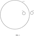
- FIG. 1 considers a scenario where a geofence 10 is in the shape of a circle.
- Location 14 represents a location of an object outside the geofence.
- Location 12 represents a location of an object inside the geofence 10.
- an alert such as a report or an alarm, may be generated.
- Such an alert may be generated each time the object crosses the geofence.
- alerts may be desirable, for instance where breach of a geofenced area may indicate a high security breach or grave danger.
- alerts may be unnecessarily burdensome to an entity monitoring the alerts.
- a precision or accuracy of a tracked location of a device being monitored may be less critical.
- frequent breach reports may drain the battery of the mobile device in a location where recharging or replacing the battery is inconvenient or impossible.
- an initial alert in response to detection of an object crossing the geofence 10, moving from location 14 to location 12, may trigger alteration of geofence 10.
- Such an alteration may reduce a frequency of alerts and allow freer movement of the object near or around a perimeter of geofence 10 without triggering breach reports.
- geofence 10 may be expanded. In one particular implementation, such an expansion may include increasing a radius of a substantially circular geofence from 'R' to 'R+X' shown at dotted circle 16 in FIG. 2 . Since both locations 12 and 14 are enclosed by the altered geofence shown at dashed circle 16, less frequent alerts may be expected from motion of the object, if motion of the object continues to be in the vicinity of the previously detected locations 12 and 14.
- an object at location 12 may escape an area bounded by a geofence to arrive at location 14.
- the object may similarly trigger or initiate frequent alerts.
- the radius of the geofence may be decreased to 'R-X' to a new geofence 18 represented by a dashed circle representing a new geofence. Since both locations 12 and 14 are outside the new geofence 18, position less frequent alerts may be expected so long as the object continues to travel in the vicinity of locations 12 and 14.
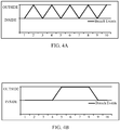
- FIGs. 4A and 4B are timing diagrams illustrating breach events in a particular implementation.
- a geofence remains static as an object that is being tracked frequently enters and then exits the geofence, triggering a breach event at each instance that the object enters and then exits an area bounded by the geofence.
- a geofence is temporarily altered following an exit of an object being tracked from an area bounded by the geofence.
- a geofence may be temporarily reduced in size (e.g., by reducing a radius of a particular geofence that is circular) to reduce the frequency of breach events.
- values for "R”, “X”, or “T” may be fine-tuned for particular applications depending on various factors, such as accuracy of position detection, criticality of the location of the geofence, anticipated motion of the object, and identification of the object as friend or foe.
- a hierarchy of concentric geofences, of increasing alert levels may be implemented where a decision of whether to alter the boundary may depend, at least in part, on which level of geofence has been breached.
- detection of a proximity of an object being tracked to a geofence, rather than an actual breach may indicate a condition for initiating an alteration of the geofence.
- a second, concentric geofence may signal a vicinity of a geofence that is to be expanded, or contracted.
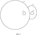
- Fig. 5 illustrates an embodiment of an alteration to a geofence.
- a mobile device is detected at locations 12 and/or 14 as crossing and/or moving in a vicinity of a boundary of a geofence 10.
- a shape of the geofence 10 is altered, as shown with expansion 20. It should be understood, however, that this is merely an example of an expansion of a geofence and claimed subject matter is not limited in this respect.
- a breach of a geofence (by either a mobile device entering or exiting a region bounded by a geofence) may be detected based, at least in part, on mapping an estimated or tracked location of the mobile device onto an area.
- the mobile device may have a positioning engine with capabilities of estimating or tracking a position of the mobile device based, at least in part, on wireless signals acquired at a receiver.
- Such acquired signals may be transmitted from a satellite positioning system (SPS) or from terrestrial transmitters using any one of several known positioning techniques.
- SPS satellite positioning system
- a mobile device may track its position using indoor navigation techniques such as, for example, obtaining range measurements to transmitters positioned at known locations (e.g., by measuring received signal strength or round-trip time) or processing signals generated from on-board inertial sensors (e.g., gyroscope, accelerometers, magnetometer, etc.).
- a positioning engine of a mobile device may incorporate measurements from multiple sources including for example, inertial sensors, acquisition of SPS signals, and acquisition of signals in an indoor environment, just to provide a few examples.
- a mobile device may track its position (e.g., by acquiring signals from an SPS or terrestrial transmitters, processing signals from inertial sensors, etc. as mentioned above) and host an application to apply the tracked position to a geofence.
- a monitoring system 601 may monitor an object 602 that does not have a capability tracking its own location.
- a monitoring system 601 may report estimated locations of object 602 or a computed trajectory of object 602 to a central server 603. Locations of object 602 may be estimated or tracked based, at least in part, on measurements or detections obtained from remote sensors using techniques such as, for example, radar, video, infrared imaging or sonar.
- Central server 603 may then implement geofence management responsive to the monitoring. Remote geofence management may be useful for a user remote from the object 602, for instance a manager supervising a sales force, an emergency dispatcher, or security personnel charged with surveillance.
- a geofence may be maintained according to a predefined size, shape and/or location.
- a geofence maintained at block 701 may comprise any particular shape or dimension (e.g., circle, ellipse, polygon, etc.).
- block 701 may maintain a geofence as a set of possible locations of a mobile device that are inside of or outside of a boundary defining the geofence.
- a geofence boundary may be defined as a discrete set of areas inside of a boundary and a set of areas bordering the geofence boundary.
- a location of an object may be monitored.
- one or more positioning technologies may be used for obtaining continuous or periodic updates of an estimated location of an object that is being tracked (e.g., acquisition of SPS signals, acquisition of signals transmitted by terrestrial transmitters, processing of signals from inertial sensors, etc.). Continuous or periodic updates of an estimated position may then be compared with a geofence.
- a size or shape of a geofence may be temporarily altered at block 704 for a duration of time (e.g., temporarily expanding the geofence if a tracked object enters the geofence and temporarily contracting the geofence if the tracked object leaves the geofence). As pointed out above, this may reduce an incidence of extraneous breach events that may reduce battery life.
- any one of several criteria may be evaluated in determining whether a geofence may be altered (e.g., altering size or shape of the geofence).
- One possible criterion may comprise a risk level associated with an object or device being monitored. For instance, if an ordinary vehicle is approaching a chemical spill or fire, it may be desirable to apply a conservative policy in alerting the vehicle operator to stay away from that hazard. In this situation, frequent alerts may be desirable.
- a geofence may be assigned or associated with a priority. For example, there may be a greater tendency or desire to alter a lower priority geofence to reduce breach reports while tolerating more frequent breach reports from a high priority geofence. For instance, in a traffic monitoring system, it may be desired to alert a driver only once if approaching an area of slow traffic, but alert the driver more frequently if the driver is approaching a road that is actually closed. Similarly, in an intrusion detection system, it may be desired to assign different priorities based, at least in part, on a particular location of a geofence or time of day. Multiple concentric geofences may enclose a hazardous location where different priorities are associated with different concentric geofences based, at least in part, on proximity to the hazardous location.
- Other possible criteria might include a number of crossings or approaches or the speed of approach by a device or object being tracked. It may be desirable to wait until a threshold number of crossings of the geofence is reached. Alternatively if the device or object being tracked approaches very quickly, the geofence may be altered sooner than if the object is approaching slowly.
- a user may establish criteria under which a geofence is to be altered. This may depend on the tolerance the user has for frequent reports or the willingness of the user to frequently charge the battery on the user's mobile device.
- FIG. 7B is a flow diagram illustrating a process temporarily altering a geofence according to an embodiment.
- a radius of a circular geofence is temporarily increased or decreased depending on whether a breach of the geofence was an entry into or an exit out of an area bounded by the geofence. It should be understood, however, that this is merely an example process of temporarily altering a geofence and claimed subject matter is not limited in this respect.
- Block 754 may determine an extent to which a geofence is to be altered and a duration "t"that the geofence is to the altered from its original state. In this particular example, "x" represents an amount that a radius of the geofence is to be temporarily increased or decreased.
- a value for x may be determined based, at least in part, on a perceived accuracy (e.g., expected error) of a position fix indicating a breach of a geofence boundary.
- a value for t may be determined based, at least in part, on user-defined settings indicating how much time movement may be ignored, in addition to an estimated speed of a tracked object. If a tracked object is perceived to be slower-moving, a value for t may be increased. Likewise, if a tracked object is perceived to be faster-moving, a value for t may be decreased.
- Diamond 758 determines whether an object being tracked enters or exits a geofence.
- a location of the object may be tracked with a series of continuous or discrete location estimates. For example, a location estimate inside of the geofence followed by a location estimate outside of the geofence may indicate that the object has exited the geofence boundary. Likewise, a location estimate outside of the geofence followed by a location estimate inside of the geofence may indicate that the object has entered the geofence boundary. If diamond 758 determines that the object is leaving or has left the area bounded by the geofence, block 760 may decrease the radius of the geofenced boundary by an x amount. Similarly, if diamond 758 determines that the object is entering or has entered the area bounded by the geofence, block 756 may increase the radius of the geofenced boundary by an x amount.
- the same value of x and value of t is applied to temporarily alter the geofence alter regardless of whether the tracked object is entering or leaving the area bounded by the geofence.
- different values for x and t may be computed depending, at least in part, on whether the object is entering or leaving.
- a geofence is maintained in an altered state (e.g., with an increased or decreased radius) until time duration t expires.
- the altered geofence may then be reset to return to its original, unaltered state at block 764 in response to expiration of time duration t . Tracking of the object may then continue at 766.
- time interval t may be partitioned into contiguous and non-overlapping epochs.
- radius R may be increased by only 7.5% of its original size following a first epoch, by only 5% of its original size following a second epoch, by only 2.5% of its original size following a third epoch, and finally returned to its original size r following a fourth epoch.
- radius R may be decreased by only 7.5% of its original size following a first epoch, by only 5% of its original size following a second epoch, by only 2.5% of its original size following a third epoch, and finally returned to its original size r following a fourth epoch.
- Implementations described above are directed to altering a size or shape of a geofence boundary in response to detection of a transition between an interior and exterior of the geofence boundary.
- other threshold conditions may be imposed for detecting a breach stemming from a transition between an interior and exterior of a geofence boundary while maintaining the size and shape of the geofence boundary static.
- a breach stemming from a transition from an interior of a geofence boundary to an exterior of the geofence boundary may be detected following or in response to a threshold time that a tracked object is determined to be located in the exterior, or a threshold number of consecutive position fixes in the exterior.
- a breach stemming from a transition from an exterior of a geofence boundary to an interior of the geofence boundary may be detected following or in response to a threshold duration that a tracked object is determined to be located in the interior, or a threshold number of consecutive position fixes in the interior.
- a size or shape of a geofence boundary may be altered as discussed above (e.g., increased in size) in response to a breach detected by a threshold duration that a tracked object is determined to be located in the interior or a number of consecutive position fixes located in the interior.
- a size or shape of a geofence boundary may be altered (e.g., decreased in size) in response to breach detected by a threshold duration that a tracked object is determined to be located in the exterior or number of consecutive position fixes located in the exterior.
- a mobile device architecture 800 may include, for example, a general purpose processor 802, a digital signal processor 804, a wireless transceiver 806, a radio receiver 808, a memory 810, and an SPS receiver 812.
- a bus 822 or other alternative structure or structures may be provided for establishing interconnections between various components of mobile device architecture 800.
- one or more interfaces 814, 816, 818, 820 may be provided between selected components and bus 822.
- the wireless transceiver 806, the radio receiver 808, and the SPS receiver 812 may each be coupled to one or more antennas 824, 826, 828, and/or other transducers, to facilitate the transmission and/or reception of wireless signals.
- the general purpose processor 802 and the digital signal processor 804 are digital processing devices that are capable of executing programs to provide one or more functions and/or services to a user.
- One or both of these processors 802, 804 may be used, for example, to execute an operating system of a corresponding wireless device.
- One or both of these processors 802, 804 may also be used, for example, to execute user application programs including, for example, location-based applications that may rely on the availability of an accurate position estimate.
- one or both of these processors 802, 804 may be used to implement, either partially or fully, one or more of the positioning related processes or techniques described herein in some implementations.
- controllers may additionally or alternatively be used to perform some or all of the described functions in various implementations including, for example, one or more controllers, microcontrollers, application specific integrated circuits (ASICs), field programmable gate arrays (FPGAs), programmable logic arrays (PLAs), programmable logic devices (PLDs), reduced instruction set computers (RISCs), and/or others, including combinations of the above.
- ASICs application specific integrated circuits
- FPGAs field programmable gate arrays
- PLAs programmable logic arrays
- PLDs programmable logic devices
- RISCs reduced instruction set computers
- Wireless transceiver 806 may include any type of transceiver that is capable of supporting wireless communication with one or more remote wireless entities.
- wireless transceiver 806 may be configured in accordance with one or more wireless networking standards and/or wireless cellular standards.
- multiple wireless transceivers may be provided to support operation with different networks or systems in a surrounding environment.
- wireless transceiver 806 may be called upon to communicate with a base station or access point of a wireless communication system or network.
- Radio receiver 808 may be operative for receiving signals from one or more sensors of a sensor network or other transmitting nodes within a surrounding environment.
- Memory 810 may include any type of device or component, or combination of devices and/or components that is capable of storing digital information (e.g., digital data, computer executable instructions and/or programs, etc.) for access by a processing device or other component.
- digital information e.g., digital data, computer executable instructions and/or programs, etc.
- This may include, for example, semiconductor memories, magnetic data storage devices, disc based storage devices, optical storage devices, read only memories (ROMs), random access memories (RAMs), non-volatile memories, flash memories, USB drives, compact disc read only memories (CD-ROMs), DVDs, Blu-Ray disks, magneto-optical disks, erasable programmable ROMs (EPROMs), electrically erasable programmable ROMs (EEPROMs), magnetic or optical cards, and/or other digital storage suitable for storing electronic instructions and/or data.
- ROMs read only memories
- RAMs random access memories
- non-volatile memories flash memories
- USB drives compact disc read only memories
- SPS receiver 812 may include any type of receiver capable of receiving SPS signals from positioning satellites and processing the signals to provide one or more position estimates for a mobile device.
- SPS receiver 812 may be configured to operate with any existing or future SPS system including, for example, the Global Positioning System (GPS), the GLONASS system, the Compass system, the Galileo system, the IRNSS system, the GNSS system and other systems that use Satellite Based Augmentation Systems (SBASs) and/or Ground Based Augmentations Systems (GBASs), and/or other satellite navigation systems.
- GPS Global Positioning System
- GLONASS Global Positioning System
- Compass system the Galileo system
- IRNSS system the GNSS system
- GNSS system Global Positioning System
- one or more of the processes or techniques described herein may be implemented, either partially or fully, within SPS receiver 812 or a similar structure.
- an SPS includes a system of transmitters positioned to enable entities to determine their location on or above the Earth based, at least in part, on signals received from the transmitters.
- a transmitter typically transmits a signal marked with a repeating pseudo-random noise (PN) code of a set number of chips and may be located on ground based control stations, user equipment and/or space vehicles.
- PN pseudo-random noise
- Such transmitters may be located on Earth orbiting space vehicles (SVs).
- a SV in a constellation of Global Navigation Satellite System such as Global Positioning System (GPS), Galileo, Glonass or Compass may transmit a signal marked with a PN code that is distinguishable from PN codes transmitted by other SVs in the constellation (e.g., using different PN codes for each satellite as in GPS or using the same code on different frequencies as in Glonass).
- GNSS Global Navigation Satellite System
- GPS Global Positioning System
- Glonass Compass
- PN codes e.g., using different PN codes for each satellite as in GPS or using the same code on different frequencies as in Glonass.
- the techniques presented herein are not restricted to global systems (e.g., GNSS) for SPS.
- the techniques provided herein may be applied to or otherwise enabled for use in various regional systems, such as, e.g., Quasi-Zenith Satellite System (QZSS) over Japan, Indian Regional Navigational Satellite System (IRNSS) over India, Beidou over China, etc., and/or various augmentation systems (e.g., an Satellite Based Augmentation System (SBAS)) that may be associated with or otherwise enabled for use with one or more global and/or regional navigation satellite systems.
- QZSS Quasi-Zenith Satellite System
- IRNSS Indian Regional Navigational Satellite System
- SBAS Satellite Based Augmentation System
- an SBAS may include an augmentation system(s) that provides integrity information, differential corrections, etc., such as, e.g., Wide Area Augmentation System (WAAS), European Geostationary Navigation Overlay Service (EGNOS), Multi-functional Satellite Augmentation System (MSAS), GPS Aided Geo Augmented Navigation or GPS and Geo Augmented Navigation system (GAGAN), and/or the like.
- WAAS Wide Area Augmentation System
- GNOS European Geostationary Navigation Overlay Service
- MSAS Multi-functional Satellite Augmentation System
- GPS Aided Geo Augmented Navigation or GPS and Geo Augmented Navigation system (GAGAN), and/or the like may include any combination of one or more global and/or regional navigation satellite systems and/or augmentation systems
- SPS signals may include SPS, SPS-like, and/or other signals associated with such one or more SPS.
- such techniques may be used with positioning systems that utilize terrestrial transmitters acting as "pseudolites", or a combination of SVs and such terrestrial transmitters.
- a processing unit may be implemented within one or more application specific integrated circuits (ASICs), digital signal processors (DSPs), digital signal processing devices (DSPDs), programmable logic devices (PLDs), field programmable gate arrays (FPGAs), processors, controllers, micro-controllers, microprocessors, electronic devices, other devices or units designed to perform the functions described herein, or combinations thereof, just to name a few examples.
- ASICs application specific integrated circuits
- DSPs digital signal processors
- DSPDs digital signal processing devices
- PLDs programmable logic devices
- FPGAs field programmable gate arrays
- processors controllers, micro-controllers, microprocessors, electronic devices, other devices or units designed to perform the functions described herein, or combinations thereof, just to name a few examples.
- the methodologies may be implemented with modules (e.g., procedures, functions, etc.) having instructions that perform the functions described herein.
- Any machine readable medium tangibly embodying instructions may be used in implementing the methodologies described herein.
- software codes may be stored in a memory and executed by a processor.
- Memory may be implemented within the processor or external to the processor.
- the term "memory" refers to any type of long term, short term, volatile, nonvolatile, or other memory and is not to be limited to any particular type of memory or number of memories, or type of media upon which memory is stored.
- one or more portions of the herein described storage media may store signals representative of data or information as expressed by a particular state of the storage media.
- an electronic signal representative of data or information may be "stored" in a portion of the storage media (e.g., memory) by affecting or changing the state of such portions of the storage media to represent data or information as binary information (e.g., ones and zeros).
- a change of state of the portion of the storage media to store a signal representative of data or information constitutes a transformation of storage media to a different state or thing.
- the functions described may be implemented in hardware, software, firmware, discrete/fixed logic circuitry, some combination thereof, and so forth. If implemented in software, the functions may be stored on a physical computer-readable medium as one or more instructions or code.
- Computer-readable media include physical computer storage media.
- a storage medium may be any available physical medium that can be accessed by a computer.
- such computer-readable media can comprise RAM, ROM, EEPROM, CD-ROM or other optical disc storage, magnetic disk storage or other magnetic storage devices, or any other medium that can be used to store desired program code in the form of instructions or data structures and that can be accessed by a computer or processor thereof.
- Disk and disc includes compact disc (CD), laser disc, optical disc, digital versatile disc (DVD), floppy disk and blue-ray disc where disks usually reproduce data magnetically, while discs reproduce data optically with lasers.
- a mobile device may be capable of communicating with one or more other devices via wireless transmission or receipt of information over various communications networks using one or more wireless communication techniques.
- wireless communication techniques may be implemented using a wireless wide area network (WWAN), a wireless local area network (WLAN), a wireless personal area network (WPAN), or the like.
- WWAN wireless wide area network
- WLAN wireless local area network
- WPAN wireless personal area network
- network and “system” may be used interchangeably herein.
- a WWAN may be a Code Division Multiple Access (CDMA) network, a Time Division Multiple Access (TDMA) network, a Frequency Division Multiple Access (FDMA) network, an Orthogonal Frequency Division Multiple Access (OFDMA) network, a Single-Carrier Frequency Division Multiple Access (SC-FDMA) network, a Long Term Evolution (LTE) network, a WiMAX (IEEE 802.16) network, and so on.
- CDMA network may implement one or more radio access technologies (RATs) such as cdma2000, Wideband-CDMA (W-CDMA), Time Division Synchronous Code Division Multiple Access (TD-SCDMA), to name just a few radio technologies.
- RATs radio access technologies
- cdma2000 may include technologies implemented according to IS-95, IS-2000, and IS-856 standards.
- a TDMA network may implement Global System for Mobile Communications (GSM), Digital Advanced Mobile Phone System (D-AMPS), or some other RAT.
- GSM and W-CDMA are described in documents from a consortium named "3rdGeneration Partnership Project” (3GPP).
- Cdma2000 is described in documents from a consortium named "3rd Generation Partnership Project 2"(3GPP2).
- 3GPP and 3GPP2 documents are publicly available.
- a WLAN may include an IEEE 802.11 x network
- a WPAN may include a Bluetooth network, an IEEE 802.15x, or some other type of network, for example.
- Wireless communication networks may include so-called next generation technologies (e.g., "4G"), such as, for example, Long Term Evolution (LTE), Advanced LTE, WiMAX, Ultra Mobile Broadband (UMB), or the like.
- 4G next generation technologies
- LTE Long Term Evolution
- UMB Ultra Mobile Broadband
- a mobile device may, for example, be capable of communicating with one or more femtocells facilitating or supporting communications with the mobile device for the purpose of estimating its location, orientation, velocity, acceleration, or the like.
- femtocell may refer to one or more smaller-size cellular base stations that may be enabled to connect to a service provider's network, for example, via broadband, such as, for example, a Digital Subscriber Line (DSL) or cable.
- DSL Digital Subscriber Line
- a femtocell may utilize or otherwise be compatible with various types of communication technology such as, for example, Universal Mobile Telecommunications System (UTMS), Long Term Evolution (LTE), Evolution-Data Optimized or Evolution-Data only (EV-DO), GSM, Worldwide Interoperability for Microwave Access (WiMAX), Code division multiple access (CDMA) -2000, or Time Division Synchronous Code Division Multiple Access (TD-SCDMA), to name just a few examples among many possible.
- UTMS Universal Mobile Telecommunications System
- LTE Long Term Evolution
- EV-DO Evolution-Data Optimized or Evolution-Data only
- GSM Global System for Mobile Communications
- WiMAX Worldwide Interoperability for Microwave Access
- CDMA Code division multiple access
- TD-SCDMA Time Division Synchronous Code Division Multiple Access
- a femtocell may comprise integrated WiFi, for example.
- WiFi Wireless Fidelity
- computer-readable code or instructions may be transmitted via signals over physical transmission media from a transmitter to a receiver (e.g., via electrical digital signals).
- software may be transmitted from a website, server, or other remote source using a coaxial cable, fiber optic cable, twisted pair, digital subscriber line (DSL), or physical components of wireless technologies such as infrared, radio, and microwave. Combinations of the above may also be included within the scope of physical transmission media.
- Such computer instructions or data may be transmitted in portions (e.g., first and second portions) at different times (e.g., at first and second times).
- the term specific apparatus or the like includes a general purpose computer once it is programmed to perform particular functions pursuant to instructions from program software.
- Algorithmic descriptions or symbolic representations are examples of techniques used by those of ordinary skill in the signal processing or related arts to convey the substance of their work to others skilled in the art.
- An algorithm is here, and generally, considered to be a self-consistent sequence of operations or similar signal processing leading to a desired result.
- operations or processing involve physical manipulation of physical quantities. Typically, although not necessarily, such quantities may take the form of electrical or magnetic signals capable of being stored, transferred, combined, compared, or otherwise manipulated.
- a special purpose computer or a similar special purpose electronic computing device is capable of manipulating or transforming signals, typically represented as physical electronic, electrical, or magnetic quantities within memories, registers, or other information storage devices, transmission devices, or display devices of the special purpose computer or similar special purpose electronic computing device.
Description
- Satellite Positioning Systems ("SPS") and other positioning technologies have been used for locating persons, things, etc. by, for example, acquiring signals transmitted by transmitters located at fixed locations. In particular implementations, positioning technologies on a mobile device may obtain a "position fix" from time to time indicating an estimate of a location of the mobile device. In combination with position fixes obtained using positioning technologies, some location based applications employ a "geofence" bounding a region of interest to detect entries into or exits from the region of interest. A geofence may comprise a virtual perimeter on a geographic area using a location-based service, so that a notification may be generated in response to the monitored device entering or exiting the area. Detection of a geofence breach may involve monitoring the position of a mobile device and detecting events triggered by the monitored position crossing the geofence.
- Further attention is drawn to document
US 2007/143013 A1 which refers to a system and method of automatically replacing the geographic location of geo-fences stored in memory of a telematics system. The location of an asset is determined using an on-board telematics device with a location device. The location of the asset is compared with the location of predefined geo-fences stored in memory on the asset. When the asset is located within a geo-fence which triggers the replacement of geo-fences, the telematics system causes the asset to receive a new set of geo-fences, which replace the existing set of geo-fences in the telematics system memory. - The document
US 2011/148626 A1 refers to a portable GPS device and portal for communicating with the GPS device and methods of use thereof. A method of tracking movement of a portable GPS device using a geofence comprises: initializing a geofence, the geofence specifying a geographic boundary; storing parameters of the geofence in a portable GPS device; sending a notification message from the portable GPS device to a remote location in response to the portable GPS device determining that it has crossed the boundary. - The document
US 2011/063138 A1 refers to an asset's TCU, or a mobile device coupled thereto, which receives and stores geographical boundary definitions to a memory. A processor uses the boundary definition to determine an initial-location boundary based on the definition and the current location of the TCU at the time it received the boundary request message. As the TCU's GPS unit generates location information, the processor retrieves the initial-location boundary definition from the memory and compares the current location from the GPS receiver to it according to an algorithm. If the processor determines that the current location of the vehicle has crossed the boundary, the processor generates an alert message and sends it wirelessly to a central computer for further processing, or directly to another device, according to a notification destination identifier. - The document
US 2010/017126 A1 refers to a method and apparatus for creating a dynamic GeoFence area by determining an instant reference point using a first set of pseudorange measurements received by a GeoFence device, defining the dynamic GeoFence area referenced to the instant reference point, determining a position fix using a second set of pseudorange measurements, and comparing the position fix to the dynamic GeoFence area. In one aspect, an alert message based on the comparison results is presented to a user. - Embodiments will now be described by way of non-limiting example with reference to the following figures. None of these drawings is intended to be proportional or to scale.
-
FIG. 1 is a diagram of a geofence according to an implementation. -
FIG. 2 is a diagram illustrating alteration of a geofence according to an embodiment. -
FIG. 3 is a diagram illustrating alteration of a geofence according to an alternative embodiment. -
FIGs. 4A and 4B are timing diagrams illustrating timing of breach events according to an embodiment. -
Fig. 5 is a diagram illustrating alteration of a geofence according to yet another alternative embodiment. -
Fig. 6 is a schematic diagram of a system to implement a geofence according to an embodiment. -
Fig. 7A is a flow diagram of a process to alter a geofence according to an embodiment. -
Fig. 7B a flow diagram of a process to later a geofence according to an alternative embodiment. -
FIG. 8 is a schematic diagram of a mobile device according to an embodiment. - In accordance with the present invention, a method as set forth in
claim 1, and an apparatus as set forth inclaim 12 are provided. Further embodiments of the invention are claimed in the dependent claims. - In one example implementation, a method comprises: detecting a breach of a geofence in response to detection that a mobile device has entered or exited a region bounded by the geofence; temporarily altering said geofence from an initial state in response to said detection of said breach; and returning said geofence to said initial state responsive to expiration of a duration.
- In another example implementation, a mobile device comprises: a receiver to acquire wireless signals; and a processor to: detect a breach of a geofence in response to detection that the mobile device has entered or exited a region bounded by the geofence based, at least in part, on said acquired signals; temporarily alter said geofence from an initial state in response to said detection of said breach; and return said geofence to said initial state responsive to expiration of a duration.
- In another example implementation, an article comprises: a non-transitory storage medium comprising machine-readable instructions stored thereon which are executable by a special purpose computing apparatus to: detect a breach of a geofence in response to detection that the mobile device has entered or exited a region bounded by the geofence; temporarily alter said geofence from an initial state in response to said detection of said breach; and return said geofence to said initial state responsive to expiration of a duration.
- In yet another example implementation, an apparatus comprises: means for detecting a breach of a geofence in response to detection that a mobile device has entered or exited a region bounded by the geofence; means for temporarily altering said geofence from an initial state in response to said detection of said breach; and means for returning said geofence to said initial state responsive to expiration of a duration.
- It should be understood, however, that these are merely example implementations provided for the purpose of illustration, and that claimed subject matter is not limited by or to any particular example implementation described herein.
- In particular applications of a geofence, if a tracked device travels along a geofence such that the device frequently crosses over the geofence (e.g., repeatedly entering and leaving an area bounded by the geofence), moving into and out of an area bounded by the geofence, the geofence may be deemed as being breached frequently. Frequent breaches may initiate an undesirable number of breach reports, which could consume transmission and power resources. Accordingly, unnecessarily frequent breach reports may diminish the utility of a geofence application for mobile devices with limited battery resources. In a particular implementation, frequent breaches of a geofence from hopping (e.g., from rapid crisscrossing the boundary of the geofence) may be addressed by manipulating the border or size of the geofence.
- Geofence embodiments described herein may be directed to a circular shape. In other implementations, however, a geofence may have other shapes or no definite shape. If an object -- such as a mobile device -- was previously outside of a geofence and then enters an area bounded by the geofence, a breach event may be detected in response. The breach event may be reported and, for a duration of time 't', a size of the geofence (e.g., a radius of the geofence if having a circular shape) may be increased from 'r' to 'r + x'. This can similarly be applied in another scenario where the object first inside and then leaving the geofenced area. Here, if is first detected that the object has left the geofence, a breach event may be reported and for an interval of time 't', the radius of the geofence may be decreased from 'r' to 'r - x'. As pointed out below, by temporarily altering a geofence in response to a breach event, unnecessary breach reports may be reduced.
-
FIG. 1 considers a scenario where ageofence 10 is in the shape of a circle.Location 14 represents a location of an object outside the geofence.Location 12 represents a location of an object inside thegeofence 10. If the object crosses the boundary of the geofence to initiate a "breach" event, an alert, such as a report or an alarm, may be generated. Such an alert may be generated each time the object crosses the geofence. In certain cases, such alerts may be desirable, for instance where breach of a geofenced area may indicate a high security breach or grave danger. At other times, however, such alerts may be unnecessarily burdensome to an entity monitoring the alerts. Here, a precision or accuracy of a tracked location of a device being monitored may be less critical. Where a geofence is being administered by a mobile device, for example carried by a user or user vehicle, frequent breach reports may drain the battery of the mobile device in a location where recharging or replacing the battery is inconvenient or impossible. - Where repeated alerts are deemed burdensome, an initial alert in response to detection of an object crossing the
geofence 10, moving fromlocation 14 tolocation 12, may trigger alteration ofgeofence 10. Such an alteration may reduce a frequency of alerts and allow freer movement of the object near or around a perimeter ofgeofence 10 without triggering breach reports. For instance,geofence 10 may be expanded. In one particular implementation, such an expansion may include increasing a radius of a substantially circular geofence from 'R' to 'R+X' shown atdotted circle 16 inFIG. 2 . Since bothlocations circle 16, less frequent alerts may be expected from motion of the object, if motion of the object continues to be in the vicinity of the previously detectedlocations - Referring again to
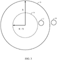
FIG. 1 in another scenario, an object atlocation 12 may escape an area bounded by a geofence to arrive atlocation 14. Here, if the object is moving along the boundary of the geofence, crisscrossing the boundary line frequently, it may similarly trigger or initiate frequent alerts. As shown inFIG. 3 , once the object is detected moving fromlocation 12 tolocation 14, the radius of the geofence may be decreased to 'R-X' to anew geofence 18 represented by a dashed circle representing a new geofence. Since bothlocations new geofence 18, position less frequent alerts may be expected so long as the object continues to travel in the vicinity oflocations -
FIGs. 4A and 4B are timing diagrams illustrating breach events in a particular implementation. AtFIG. 4A , a geofence remains static as an object that is being tracked frequently enters and then exits the geofence, triggering a breach event at each instance that the object enters and then exits an area bounded by the geofence. In the embodiment ofFIG. 4B , on the other hand, a geofence is temporarily altered following an exit of an object being tracked from an area bounded by the geofence. In this particular example, a geofence may be temporarily reduced in size (e.g., by reducing a radius of a particular geofence that is circular) to reduce the frequency of breach events. - In particular implementations, values for "R", "X", or "T" may be fine-tuned for particular applications depending on various factors, such as accuracy of position detection, criticality of the location of the geofence, anticipated motion of the object, and identification of the object as friend or foe.
- In particular embodiments, a hierarchy of concentric geofences, of increasing alert levels may be implemented where a decision of whether to alter the boundary may depend, at least in part, on which level of geofence has been breached. In other embodiments, detection of a proximity of an object being tracked to a geofence, rather than an actual breach may indicate a condition for initiating an alteration of the geofence. A second, concentric geofence may signal a vicinity of a geofence that is to be expanded, or contracted.
-
Fig. 5 illustrates an embodiment of an alteration to a geofence. According to an alternative implementation, a mobile device is detected atlocations 12 and/or 14 as crossing and/or moving in a vicinity of a boundary of ageofence 10. In response, a shape of thegeofence 10 is altered, as shown withexpansion 20. It should be understood, however, that this is merely an example of an expansion of a geofence and claimed subject matter is not limited in this respect. - A breach of a geofence (by either a mobile device entering or exiting a region bounded by a geofence) may be detected based, at least in part, on mapping an estimated or tracked location of the mobile device onto an area. Here, the mobile device may have a positioning engine with capabilities of estimating or tracking a position of the mobile device based, at least in part, on wireless signals acquired at a receiver. Such acquired signals may be transmitted from a satellite positioning system (SPS) or from terrestrial transmitters using any one of several known positioning techniques. In other implementations, a mobile device may track its position using indoor navigation techniques such as, for example, obtaining range measurements to transmitters positioned at known locations (e.g., by measuring received signal strength or round-trip time) or processing signals generated from on-board inertial sensors (e.g., gyroscope, accelerometers, magnetometer, etc.). In other implementations, a positioning engine of a mobile device may incorporate measurements from multiple sources including for example, inertial sensors, acquisition of SPS signals, and acquisition of signals in an indoor environment, just to provide a few examples.
- In particular implementations, a mobile device may track its position (e.g., by acquiring signals from an SPS or terrestrial transmitters, processing signals from inertial sensors, etc. as mentioned above) and host an application to apply the tracked position to a geofence. In an alternative implementation illustrated in
FIG. 6 , amonitoring system 601 may monitor anobject 602 that does not have a capability tracking its own location. Amonitoring system 601 may report estimated locations ofobject 602 or a computed trajectory ofobject 602 to acentral server 603. Locations ofobject 602 may be estimated or tracked based, at least in part, on measurements or detections obtained from remote sensors using techniques such as, for example, radar, video, infrared imaging or sonar.Central server 603 may then implement geofence management responsive to the monitoring. Remote geofence management may be useful for a user remote from theobject 602, for instance a manager supervising a sales force, an emergency dispatcher, or security personnel charged with surveillance. - Flow diagrams discussed herein are not intended to limit the location or implementation of operations or devices, and in no way are intended to limit claimed subject matter. Thus boxes of a single diagram chart may occur in the same or different devices. A single box may be distributed over more than one device.
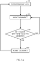
- 7A is a flowchart of a process in accordance with an embodiment. At
block 701, a geofence may be maintained according to a predefined size, shape and/or location. As indicated above, a geofence maintained atblock 701 may comprise any particular shape or dimension (e.g., circle, ellipse, polygon, etc.). In one example, block 701 may maintain a geofence as a set of possible locations of a mobile device that are inside of or outside of a boundary defining the geofence. In alternative implementations, a geofence boundary may be defined as a discrete set of areas inside of a boundary and a set of areas bordering the geofence boundary. Atblock 702, a location of an object (e.g., mobile device) may be monitored. In one particular implementation, one or more positioning technologies may be used for obtaining continuous or periodic updates of an estimated location of an object that is being tracked (e.g., acquisition of SPS signals, acquisition of signals transmitted by terrestrial transmitters, processing of signals from inertial sensors, etc.). Continuous or periodic updates of an estimated position may then be compared with a geofence. - As discussed above, in one particular implementation, a size or shape of a geofence may be temporarily altered at
block 704 for a duration of time (e.g., temporarily expanding the geofence if a tracked object enters the geofence and temporarily contracting the geofence if the tracked object leaves the geofence). As pointed out above, this may reduce an incidence of extraneous breach events that may reduce battery life. - In particular implementations, at diamond 703 any one of several criteria may be evaluated in determining whether a geofence may be altered (e.g., altering size or shape of the geofence). One possible criterion may comprise a risk level associated with an object or device being monitored. For instance, if an ordinary vehicle is approaching a chemical spill or fire, it may be desirable to apply a conservative policy in alerting the vehicle operator to stay away from that hazard. In this situation, frequent alerts may be desirable.
- In another implementation, a geofence may be assigned or associated with a priority. For example, there may be a greater tendency or desire to alter a lower priority geofence to reduce breach reports while tolerating more frequent breach reports from a high priority geofence. For instance, in a traffic monitoring system, it may be desired to alert a driver only once if approaching an area of slow traffic, but alert the driver more frequently if the driver is approaching a road that is actually closed. Similarly, in an intrusion detection system, it may be desired to assign different priorities based, at least in part, on a particular location of a geofence or time of day. Multiple concentric geofences may enclose a hazardous location where different priorities are associated with different concentric geofences based, at least in part, on proximity to the hazardous location.
- Other possible criteria might include a number of crossings or approaches or the speed of approach by a device or object being tracked. It may be desirable to wait until a threshold number of crossings of the geofence is reached. Alternatively if the device or object being tracked approaches very quickly, the geofence may be altered sooner than if the object is approaching slowly.
- In other implementations, a user may establish criteria under which a geofence is to be altered. This may depend on the tolerance the user has for frequent reports or the willingness of the user to frequently charge the battery on the user's mobile device.
-
FIG. 7B is a flow diagram illustrating a process temporarily altering a geofence according to an embodiment. In this particular example, a radius of a circular geofence is temporarily increased or decreased depending on whether a breach of the geofence was an entry into or an exit out of an area bounded by the geofence. It should be understood, however, that this is merely an example process of temporarily altering a geofence and claimed subject matter is not limited in this respect. At 752, a geofence breach is detected by, for example, comparing an updated estimate of a location of an object with an area defined by the geofence.Block 754 may determine an extent to which a geofence is to be altered and a duration "t"that the geofence is to the altered from its original state. In this particular example, "x" represents an amount that a radius of the geofence is to be temporarily increased or decreased. - Any one of several factors may be considered or evaluated in determining values for t or x. For example, a value for x may be determined based, at least in part, on a perceived accuracy (e.g., expected error) of a position fix indicating a breach of a geofence boundary. A value for t may be determined based, at least in part, on user-defined settings indicating how much time movement may be ignored, in addition to an estimated speed of a tracked object. If a tracked object is perceived to be slower-moving, a value for t may be increased. Likewise, if a tracked object is perceived to be faster-moving, a value for t may be decreased.
-
Diamond 758 determines whether an object being tracked enters or exits a geofence. In one implementation, a location of the object may be tracked with a series of continuous or discrete location estimates. For example, a location estimate inside of the geofence followed by a location estimate outside of the geofence may indicate that the object has exited the geofence boundary. Likewise, a location estimate outside of the geofence followed by a location estimate inside of the geofence may indicate that the object has entered the geofence boundary. Ifdiamond 758 determines that the object is leaving or has left the area bounded by the geofence, block 760 may decrease the radius of the geofenced boundary by an x amount. Similarly, ifdiamond 758 determines that the object is entering or has entered the area bounded by the geofence, block 756 may increase the radius of the geofenced boundary by an x amount. - In the particular implementation shown in
FIG. 7B , the same value of x and value of t is applied to temporarily alter the geofence alter regardless of whether the tracked object is entering or leaving the area bounded by the geofence. In other embodiments, different values for x and t may be computed depending, at least in part, on whether the object is entering or leaving. - At
block 762, a geofence is maintained in an altered state (e.g., with an increased or decreased radius) until time duration t expires. The altered geofence may then be reset to return to its original, unaltered state atblock 764 in response to expiration of time duration t. Tracking of the object may then continue at 766. In an alternative implementation, instead of entirely restoring the radius of a circular geofence to R = r all at once on expiration of time interval t as illustrated atblocks process 750 may gradually restore the radius R = rover time. Here, time interval t may be partitioned into contiguous and non-overlapping epochs. If a size of radius R is increased over its original size by 10% atblock 756, for example, radius R may be increased by only 7.5% of its original size following a first epoch, by only 5% of its original size following a second epoch, by only 2.5% of its original size following a third epoch, and finally returned to its original size r following a fourth epoch. Similarly, if a size of radius R is decreased from its original size by 10% atblock 760, for example, radius R may be decreased by only 7.5% of its original size following a first epoch, by only 5% of its original size following a second epoch, by only 2.5% of its original size following a third epoch, and finally returned to its original size r following a fourth epoch. - Implementations described above are directed to altering a size or shape of a geofence boundary in response to detection of a transition between an interior and exterior of the geofence boundary. In an alternative implementation, instead of altering a size or shape of a geofence, other threshold conditions may be imposed for detecting a breach stemming from a transition between an interior and exterior of a geofence boundary while maintaining the size and shape of the geofence boundary static. For example, a breach stemming from a transition from an interior of a geofence boundary to an exterior of the geofence boundary may be detected following or in response to a threshold time that a tracked object is determined to be located in the exterior, or a threshold number of consecutive position fixes in the exterior. Likewise, a breach stemming from a transition from an exterior of a geofence boundary to an interior of the geofence boundary may be detected following or in response to a threshold duration that a tracked object is determined to be located in the interior, or a threshold number of consecutive position fixes in the interior. In yet another alternative implementation, a size or shape of a geofence boundary may be altered as discussed above (e.g., increased in size) in response to a breach detected by a threshold duration that a tracked object is determined to be located in the interior or a number of consecutive position fixes located in the interior. Likewise, a size or shape of a geofence boundary may be altered (e.g., decreased in size) in response to breach detected by a threshold duration that a tracked object is determined to be located in the exterior or number of consecutive position fixes located in the exterior.
- As illustrated in
FIG. 8 according to a particular implementation, amobile device architecture 800 may include, for example, ageneral purpose processor 802, adigital signal processor 804, awireless transceiver 806, aradio receiver 808, amemory 810, and anSPS receiver 812. Abus 822 or other alternative structure or structures may be provided for establishing interconnections between various components ofmobile device architecture 800. In the illustrated implementation, one ormore interfaces bus 822. Thewireless transceiver 806, theradio receiver 808, and theSPS receiver 812 may each be coupled to one ormore antennas - The
general purpose processor 802 and thedigital signal processor 804 are digital processing devices that are capable of executing programs to provide one or more functions and/or services to a user. One or both of theseprocessors processors processors -
Wireless transceiver 806 may include any type of transceiver that is capable of supporting wireless communication with one or more remote wireless entities. In various implementations,wireless transceiver 806 may be configured in accordance with one or more wireless networking standards and/or wireless cellular standards. In some implementations, multiple wireless transceivers may be provided to support operation with different networks or systems in a surrounding environment. During mobile device operation,wireless transceiver 806 may be called upon to communicate with a base station or access point of a wireless communication system or network.Radio receiver 808 may be operative for receiving signals from one or more sensors of a sensor network or other transmitting nodes within a surrounding environment. -
Memory 810 may include any type of device or component, or combination of devices and/or components that is capable of storing digital information (e.g., digital data, computer executable instructions and/or programs, etc.) for access by a processing device or other component. This may include, for example, semiconductor memories, magnetic data storage devices, disc based storage devices, optical storage devices, read only memories (ROMs), random access memories (RAMs), non-volatile memories, flash memories, USB drives, compact disc read only memories (CD-ROMs), DVDs, Blu-Ray disks, magneto-optical disks, erasable programmable ROMs (EPROMs), electrically erasable programmable ROMs (EEPROMs), magnetic or optical cards, and/or other digital storage suitable for storing electronic instructions and/or data. -
SPS receiver 812 may include any type of receiver capable of receiving SPS signals from positioning satellites and processing the signals to provide one or more position estimates for a mobile device.SPS receiver 812 may be configured to operate with any existing or future SPS system including, for example, the Global Positioning System (GPS), the GLONASS system, the Compass system, the Galileo system, the IRNSS system, the GNSS system and other systems that use Satellite Based Augmentation Systems (SBASs) and/or Ground Based Augmentations Systems (GBASs), and/or other satellite navigation systems. In some implementations, one or more of the processes or techniques described herein may be implemented, either partially or fully, withinSPS receiver 812 or a similar structure. - In particular implementations, an SPS includes a system of transmitters positioned to enable entities to determine their location on or above the Earth based, at least in part, on signals received from the transmitters. Such a transmitter typically transmits a signal marked with a repeating pseudo-random noise (PN) code of a set number of chips and may be located on ground based control stations, user equipment and/or space vehicles. In a particular example, such transmitters may be located on Earth orbiting space vehicles (SVs). For example, a SV in a constellation of Global Navigation Satellite System (GNSS) such as Global Positioning System (GPS), Galileo, Glonass or Compass may transmit a signal marked with a PN code that is distinguishable from PN codes transmitted by other SVs in the constellation (e.g., using different PN codes for each satellite as in GPS or using the same code on different frequencies as in Glonass). In accordance with certain aspects, the techniques presented herein are not restricted to global systems (e.g., GNSS) for SPS. For example, the techniques provided herein may be applied to or otherwise enabled for use in various regional systems, such as, e.g., Quasi-Zenith Satellite System (QZSS) over Japan, Indian Regional Navigational Satellite System (IRNSS) over India, Beidou over China, etc., and/or various augmentation systems (e.g., an Satellite Based Augmentation System (SBAS)) that may be associated with or otherwise enabled for use with one or more global and/or regional navigation satellite systems. By way of example but not limitation, an SBAS may include an augmentation system(s) that provides integrity information, differential corrections, etc., such as, e.g., Wide Area Augmentation System (WAAS), European Geostationary Navigation Overlay Service (EGNOS), Multi-functional Satellite Augmentation System (MSAS), GPS Aided Geo Augmented Navigation or GPS and Geo Augmented Navigation system (GAGAN), and/or the like. Thus, as used herein an SPS may include any combination of one or more global and/or regional navigation satellite systems and/or augmentation systems, and SPS signals may include SPS, SPS-like, and/or other signals associated with such one or more SPS. Furthermore, such techniques may be used with positioning systems that utilize terrestrial transmitters acting as "pseudolites", or a combination of SVs and such terrestrial transmitters.
- Methodologies described herein may be implemented by various means depending upon applications according to particular features or examples. For example, such methodologies may be implemented in hardware, firmware, software, discrete/fixed logic circuitry, any combination thereof, and so forth. In a hardware or logic circuitry implementation, for example, a processing unit may be implemented within one or more application specific integrated circuits (ASICs), digital signal processors (DSPs), digital signal processing devices (DSPDs), programmable logic devices (PLDs), field programmable gate arrays (FPGAs), processors, controllers, micro-controllers, microprocessors, electronic devices, other devices or units designed to perform the functions described herein, or combinations thereof, just to name a few examples.
- For a firmware or software implementation, the methodologies may be implemented with modules (e.g., procedures, functions, etc.) having instructions that perform the functions described herein. Any machine readable medium tangibly embodying instructions may be used in implementing the methodologies described herein. For example, software codes may be stored in a memory and executed by a processor. Memory may be implemented within the processor or external to the processor. As used herein the term "memory" refers to any type of long term, short term, volatile, nonvolatile, or other memory and is not to be limited to any particular type of memory or number of memories, or type of media upon which memory is stored. In at least some implementations, one or more portions of the herein described storage media may store signals representative of data or information as expressed by a particular state of the storage media. For example, an electronic signal representative of data or information may be "stored" in a portion of the storage media (e.g., memory) by affecting or changing the state of such portions of the storage media to represent data or information as binary information (e.g., ones and zeros). As such, in a particular implementation, such a change of state of the portion of the storage media to store a signal representative of data or information constitutes a transformation of storage media to a different state or thing.
- As was indicated, in one or more example implementations, the functions described may be implemented in hardware, software, firmware, discrete/fixed logic circuitry, some combination thereof, and so forth. If implemented in software, the functions may be stored on a physical computer-readable medium as one or more instructions or code. Computer-readable media include physical computer storage media. A storage medium may be any available physical medium that can be accessed by a computer. By way of example, and not limitation, such computer-readable media can comprise RAM, ROM, EEPROM, CD-ROM or other optical disc storage, magnetic disk storage or other magnetic storage devices, or any other medium that can be used to store desired program code in the form of instructions or data structures and that can be accessed by a computer or processor thereof. Disk and disc, as used herein, includes compact disc (CD), laser disc, optical disc, digital versatile disc (DVD), floppy disk and blue-ray disc where disks usually reproduce data magnetically, while discs reproduce data optically with lasers.
- As discussed above, a mobile device may be capable of communicating with one or more other devices via wireless transmission or receipt of information over various communications networks using one or more wireless communication techniques. Here, for example, wireless communication techniques may be implemented using a wireless wide area network (WWAN), a wireless local area network (WLAN),a wireless personal area network (WPAN), or the like. The term "network" and "system" may be used interchangeably herein. A WWAN may be a Code Division Multiple Access (CDMA) network, a Time Division Multiple Access (TDMA) network, a Frequency Division Multiple Access (FDMA) network, an Orthogonal Frequency Division Multiple Access (OFDMA) network, a Single-Carrier Frequency Division Multiple Access (SC-FDMA) network, a Long Term Evolution (LTE) network, a WiMAX (IEEE 802.16) network, and so on. A CDMA network may implement one or more radio access technologies (RATs) such as cdma2000, Wideband-CDMA (W-CDMA), Time Division Synchronous Code Division Multiple Access (TD-SCDMA), to name just a few radio technologies. Here, cdma2000 may include technologies implemented according to IS-95, IS-2000, and IS-856 standards. A TDMA network may implement Global System for Mobile Communications (GSM), Digital Advanced Mobile Phone System (D-AMPS), or some other RAT. GSM and W-CDMA are described in documents from a consortium named "3rdGeneration Partnership Project" (3GPP). Cdma2000 is described in documents from a consortium named "3rd
Generation Partnership Project 2"(3GPP2). 3GPP and 3GPP2 documents are publicly available. A WLAN may include an IEEE 802.11 x network, and a WPAN may include a Bluetooth network, an IEEE 802.15x, or some other type of network, for example. The techniques may also be implemented in conjunction with any combination of WWAN, WLAN, or WPAN. Wireless communication networks may include so-called next generation technologies (e.g., "4G"), such as, for example, Long Term Evolution (LTE), Advanced LTE, WiMAX, Ultra Mobile Broadband (UMB), or the like. - In one particular implementation, a mobile device may, for example, be capable of communicating with one or more femtocells facilitating or supporting communications with the mobile device for the purpose of estimating its location, orientation, velocity, acceleration, or the like. As used herein, "femtocell" may refer to one or more smaller-size cellular base stations that may be enabled to connect to a service provider's network, for example, via broadband, such as, for example, a Digital Subscriber Line (DSL) or cable. Typically, although not necessarily, a femtocell may utilize or otherwise be compatible with various types of communication technology such as, for example, Universal Mobile Telecommunications System (UTMS), Long Term Evolution (LTE), Evolution-Data Optimized or Evolution-Data only (EV-DO), GSM, Worldwide Interoperability for Microwave Access (WiMAX), Code division multiple access (CDMA) -2000, or Time Division Synchronous Code Division Multiple Access (TD-SCDMA), to name just a few examples among many possible. In certain implementations, a femtocell may comprise integrated WiFi, for example. However, such details relating to femtocells are merely examples, and claimed subject matter is not so limited.
- Also, computer-readable code or instructions may be transmitted via signals over physical transmission media from a transmitter to a receiver (e.g., via electrical digital signals). For example, software may be transmitted from a website, server, or other remote source using a coaxial cable, fiber optic cable, twisted pair, digital subscriber line (DSL), or physical components of wireless technologies such as infrared, radio, and microwave. Combinations of the above may also be included within the scope of physical transmission media. Such computer instructions or data may be transmitted in portions (e.g., first and second portions) at different times (e.g., at first and second times).Some portions of this Detailed Description are presented in terms of algorithms or symbolic representations of operations on binary digital signals stored within a memory of a specific apparatus or special purpose computing device or platform. In the context of this particular Specification, the term specific apparatus or the like includes a general purpose computer once it is programmed to perform particular functions pursuant to instructions from program software. Algorithmic descriptions or symbolic representations are examples of techniques used by those of ordinary skill in the signal processing or related arts to convey the substance of their work to others skilled in the art. An algorithm is here, and generally, considered to be a self-consistent sequence of operations or similar signal processing leading to a desired result. In this context, operations or processing involve physical manipulation of physical quantities. Typically, although not necessarily, such quantities may take the form of electrical or magnetic signals capable of being stored, transferred, combined, compared, or otherwise manipulated.
- It has proven convenient at times, principally for reasons of common usage, to refer to such signals as bits, information, values, elements, symbols, characters, variables, terms, numbers, numerals, or the like. It should be understood, however, that all of these or similar terms are to be associated with appropriate physical quantities and are merely convenient labels. Unless specifically stated otherwise, as is apparent from the discussion above, it is appreciated that throughout this Specification discussions utilizing terms such as "processing," "computing," "calculating," "determining," "ascertaining," "identifying," "associating," "measuring," "performing," or the like refer to actions or processes of a specific apparatus, such as a special purpose computer or a similar special purpose electronic computing device. In the context of this Specification, therefore, a special purpose computer or a similar special purpose electronic computing device is capable of manipulating or transforming signals, typically represented as physical electronic, electrical, or magnetic quantities within memories, registers, or other information storage devices, transmission devices, or display devices of the special purpose computer or similar special purpose electronic computing device.
- Terms, "and" and "or" as used herein, may include a variety of meanings that also is expected to depend at least in part upon the context in which such terms are used. Typically, "or" if used to associate a list, such as A, B, or C, is intended to mean A, B, and C, here used in the inclusive sense, as well as A, B, or C, here used in the exclusive sense. In addition, the term "one or more" as used herein may be used to describe any feature, structure, or characteristic in the singular or may be used to describe some combination of features, structures or characteristics. Though, it should be noted that this is merely an illustrative example and claimed subject matter is not limited to this example.
- While certain example techniques have been described and shown herein using various methods or systems, it should be understood by those skilled in the art that various other modifications may be made, and equivalents may be substituted, without departing from claimed subject matter. Additionally, many modifications may be made to adapt a particular situation to the teachings of claimed subject matter without departing from the central concept described herein. Therefore, it is intended that claimed subject matter not be limited to particular examples disclosed, but that such claimed subject matter may also include all implementations falling within the scope of the appended claims, and equivalents thereof.
- The word "a" or "an" as used in the claims should not be read as precluding more than one of the thus recited elements. The word "comprising" is used herein synonymously with the word "including."
- The claims and specification herein may include anthropomorphic or algorithmic language, Nevertheless there is no intent here to claim human mental or manual operations. All claimed operations are intended to occur in automated fashion in one or more apparatuses.
Claims (15)
- A method (750) comprising:detecting (752) a breach of a geofence in response to detection that a mobile device (800) has entered or exited a region bounded by the geofence;temporarily expanding (756) or contracting (760) said region bounded by said geofence from an initial state in response to said detection of said breach for a set duration starting at said detection; andreturning (764) said geofence to said initial state responsive to expiration (762) of said set duration.
- The method (750) of claim 1, wherein said initial state is characterized by a size of an area bounded by the geofence.
- The method (750) of claim 2, wherein said geofence comprises a circular geofence, and wherein temporarily expanding (756) or contracting (760) said region bounded by said geofence comprises changing a radius of said circular geofence.
- The method (750) of claim 3, wherein temporarily expanding (756) or contracting (760) said geofence comprises temporarily increasing the radius of said circular geofence in response to detecting that said mobile device (800) has entered an area bounded by said geofence.
- The method (750) of claim 3, wherein temporarily expanding (756) or contracting (760) said geofence comprises temporarily decreasing the radius of said circular geofence in response to detecting that said mobile device (800) has exited an area bounded by said geofence.
- The method (750) of claim 1, wherein said geofence comprises a polygonal shape.
- The method (750) of claim 1, wherein detecting (752) the breach further comprises:obtaining a trajectory of said mobile device (800); anddetermining whether the mobile device has entered or exited the geofence in response to determining that said trajectory crosses the geofence.
- The method (750) of claim 7, and further comprising computing said trajectory based, at least in part, on a sequence of two or more estimates of a location of said mobile device (800).
- The method (750) of claim 7, and further comprising computing said trajectory based, at least in part, on measurements obtained from one or more inertial sensors on-board said mobile device (800).
- The method (750) of claim 1, wherein returning said geofence to said initial state responsive to expiration of said duration comprises returning said geofence to said initial state over increments within said duration.
- An article comprising:
a non-transitory storage medium comprising machine-readable instructions stored thereon which when executed by a special purpose computing apparatus cause the special purpose computing apparatus to carry out any of the method steps of claims 1 to 10. - An apparatus comprising:means for detecting a breach of a geofence in response to detection that a mobile device (800) has entered or exited a region bounded by the geofence;means for temporarily expanding or contracting a region bounded by said geofence from an initial state in response to said detection of said breach for a set duration starting at said detection; andmeans for returning said geofence to said initial state responsive to expiration of said set duration.
- The apparatus of claim 12, wherein said means for detecting the breach further comprises:means for obtaining a trajectory of said mobile device (800); andmeans for determining whether the mobile device (800) has entered or exited the geofence in response to determining that said trajectory crosses the geofence.
- The apparatus of claim 13, and further comprising means for computing said trajectory based, at least in part, on a sequence of two or more estimates of a location of said mobile device (800).
- The apparatus of claim 13, and further comprising means for computing said trajectory based, at least in part, on measurements obtained from one or more inertial sensors on-board said mobile device (800).
Applications Claiming Priority (3)
| Application Number | Priority Date | Filing Date | Title |
|---|---|---|---|
| US201161549619P | 2011-10-20 | 2011-10-20 | |
| US13/529,782 US8941489B2 (en) | 2011-10-20 | 2012-06-21 | Method and/or apparatus for geofence management |
| PCT/US2012/057496 WO2013058954A1 (en) | 2011-10-20 | 2012-09-27 | Method and/or apparatus for geofence management |
Publications (2)
| Publication Number | Publication Date |
|---|---|
| EP2769561A1 EP2769561A1 (en) | 2014-08-27 |
| EP2769561B1 true EP2769561B1 (en) | 2018-05-30 |
Family
ID=48135519
Family Applications (1)
| Application Number | Title | Priority Date | Filing Date |
|---|---|---|---|
| EP12781204.8A Active EP2769561B1 (en) | 2011-10-20 | 2012-09-27 | Method and/or apparatus for geofence management |
Country Status (6)
| Country | Link |
|---|---|
| US (1) | US8941489B2 (en) |
| EP (1) | EP2769561B1 (en) |
| JP (1) | JP5886439B2 (en) |
| KR (1) | KR101570715B1 (en) |
| CN (1) | CN103947229B (en) |
| WO (1) | WO2013058954A1 (en) |
Families Citing this family (137)
| Publication number | Priority date | Publication date | Assignee | Title |
|---|---|---|---|---|
| US8406783B2 (en) * | 2008-10-10 | 2013-03-26 | Qualcomm Incorporated | Geographical boundary based tracking |
| US9880604B2 (en) | 2011-04-20 | 2018-01-30 | Microsoft Technology Licensing, Llc | Energy efficient location detection |
| US10715380B2 (en) * | 2011-05-23 | 2020-07-14 | Apple Inc. | Setting a reminder that is triggered by a target user device |
| US9115908B2 (en) | 2011-07-27 | 2015-08-25 | Honeywell International Inc. | Systems and methods for managing a programmable thermostat |
| US9210545B2 (en) | 2012-06-05 | 2015-12-08 | Apple Inc. | Managing alerts based on context |
| US9247378B2 (en) | 2012-08-07 | 2016-01-26 | Honeywell International Inc. | Method for controlling an HVAC system using a proximity aware mobile device |
| US9043329B1 (en) * | 2013-12-19 | 2015-05-26 | Banjo, Inc. | Dynamic event detection system and method |
| US20150095355A1 (en) * | 2012-11-15 | 2015-04-02 | Banjo, Inc. | Systems and methods for dynamic event content curation |
| US9652525B2 (en) | 2012-10-02 | 2017-05-16 | Banjo, Inc. | Dynamic event detection system and method |
| US10360352B2 (en) | 2012-10-02 | 2019-07-23 | Banjo, Inc. | System and method for event-based vehicle operation |
| US10678815B2 (en) | 2012-10-02 | 2020-06-09 | Banjo, Inc. | Dynamic event detection system and method |
| US9934368B2 (en) | 2012-10-02 | 2018-04-03 | Banjo, Inc. | User-generated content permissions status analysis system and method |
| US9817997B2 (en) | 2014-12-18 | 2017-11-14 | Banjo, Inc. | User-generated content permissions status analysis system and method |
| US9210540B2 (en) | 2012-11-08 | 2015-12-08 | xAd, Inc. | Method and apparatus for geographic document retrieval |
| US9212916B2 (en) * | 2012-11-26 | 2015-12-15 | Blackberry Limited | Systems and methods for indoor navigation |
| US9432806B2 (en) | 2012-12-04 | 2016-08-30 | Ebay Inc. | Dynamic geofence based on members within |
| US9589435B2 (en) * | 2012-12-14 | 2017-03-07 | Qualcomm Incorporated | Providing alerts, vouchers, or coupons once a plurality of geo-fences have been breached a number of times |
| US9998866B2 (en) | 2013-06-14 | 2018-06-12 | Microsoft Technology Licensing, Llc | Detecting geo-fence events using varying confidence levels |
| US9820231B2 (en) * | 2013-06-14 | 2017-11-14 | Microsoft Technology Licensing, Llc | Coalescing geo-fence events |
| US9386415B2 (en) | 2013-07-17 | 2016-07-05 | Qualcomm Incorporated | Geofences based on RF fingerprints |
| US9351114B2 (en) * | 2013-07-25 | 2016-05-24 | Square, Inc. | Generating geofences |
| WO2015013099A2 (en) * | 2013-07-25 | 2015-01-29 | Square, Inc. | Generating geofences |
| US20150057024A1 (en) * | 2013-08-22 | 2015-02-26 | Locus Location Systems, Llc | Method And System For Tracking, Controlling, Monitoring And Dispatching Devices Based On Geo-Location Information Shared Through A Controlling Hierarchy |
| US9247408B2 (en) | 2013-10-22 | 2016-01-26 | Patrocinium Systems LLC | Interactive emergency information and identification |
| US9572002B2 (en) | 2013-10-22 | 2017-02-14 | Patrocinium Systems LLC | Interactive emergency information and identification systems and methods |
| US9936346B2 (en) * | 2013-11-28 | 2018-04-03 | Microsoft Technology Licensing, Llc | Geofences from context and crowd-sourcing |
| US10136251B2 (en) * | 2013-11-28 | 2018-11-20 | Microsoft Technology Licensing, Llc | Geofence compositions |
| CN105900458B (en) * | 2013-12-02 | 2019-08-06 | 阿尔弗雷德·卡赫欧洲两合公司 | For monitoring the method used and information system of surface processing device |
| CN105850157B (en) | 2013-12-02 | 2020-03-06 | 阿尔弗雷德·卡赫欧洲两合公司 | Method and monitoring system for monitoring a place of use of a surface treatment device |
| US9307359B2 (en) * | 2013-12-05 | 2016-04-05 | Ebay Inc. | Methods, systems, and apparatus for a geo-fence system |
| US20150163945A1 (en) | 2013-12-11 | 2015-06-11 | Honeywell International Inc. | Hvac controller with thermistor biased against an outer housing |
| US20150181016A1 (en) * | 2013-12-20 | 2015-06-25 | Ebay Inc. | System and method to utilize geo-fences to limit calls to a server system from a user's mobile device |
| US9408031B1 (en) | 2014-01-09 | 2016-08-02 | Skyhook Wireless, Inc. | Geo-fence splitting |
| US9628950B1 (en) * | 2014-01-12 | 2017-04-18 | Investment Asset Holdings Llc | Location-based messaging |
| CN106068656B (en) * | 2014-02-11 | 2020-11-06 | 谷歌有限责任公司 | Virtual geographic perimeter composed of multiple component shapes |
| WO2015139078A1 (en) * | 2014-03-21 | 2015-09-24 | Bluedot Innovation Pty Ltd | Geofencing method and arrangement |
| US10318990B2 (en) | 2014-04-01 | 2019-06-11 | Ebay Inc. | Selecting users relevant to a geofence |
| US9774995B2 (en) * | 2014-05-09 | 2017-09-26 | Microsoft Technology Licensing, Llc | Location tracking based on overlapping geo-fences |
| US9256994B2 (en) * | 2014-05-12 | 2016-02-09 | Unmanned Innovation, Inc. | Unmanned aerial vehicle authorization and geofence envelope determination |
| US9273981B1 (en) | 2014-05-12 | 2016-03-01 | Unmanned Innovation, Inc. | Distributed unmanned aerial vehicle architecture |
| US11959749B2 (en) * | 2014-06-20 | 2024-04-16 | Profound Positioning Inc. | Mobile mapping system |
| EP3162093A4 (en) * | 2014-06-24 | 2017-11-29 | Intel Corporation | Apparatus,system and method of geofencing |
| US9503853B2 (en) | 2014-07-01 | 2016-11-22 | At&T Mobility Ii Llc | Aggregation of mobile device data for facilitation of rule-based action |
| US10824654B2 (en) | 2014-09-18 | 2020-11-03 | Snap Inc. | Geolocation-based pictographs |
| WO2016053839A1 (en) | 2014-09-29 | 2016-04-07 | Laird Technologies, Inc. | Starter overrides for telematics devices and corresponding methods |
| CN105635960A (en) * | 2014-11-19 | 2016-06-01 | 中兴通讯股份有限公司 | Terminal management method, terminal management apparatus and terminal management system |
| CN105744473A (en) | 2014-12-08 | 2016-07-06 | 阿里巴巴集团控股有限公司 | Geo-fencing-based positioning method and device |
| US10506365B1 (en) * | 2015-02-12 | 2019-12-10 | Amazon Technologies, Inc. | Power efficient dynamic geofences |
| WO2016130994A1 (en) * | 2015-02-13 | 2016-08-18 | Unmanned Innovation, Inc. | Unmanned aerial vehicle remote flight planning system |
| EP3266228B1 (en) * | 2015-03-02 | 2019-06-19 | Telefonaktiebolaget LM Ericsson (publ) | Localized network service |
| US9900174B2 (en) | 2015-03-06 | 2018-02-20 | Honeywell International Inc. | Multi-user geofencing for building automation |
| KR102163528B1 (en) | 2015-03-18 | 2020-10-08 | 스냅 인코포레이티드 | Geo-fence authorization provisioning |
| US9967391B2 (en) | 2015-03-25 | 2018-05-08 | Honeywell International Inc. | Geo-fencing in a building automation system |
| WO2016154943A1 (en) | 2015-03-31 | 2016-10-06 | SZ DJI Technology Co., Ltd. | Systems and methods for geo-fencing device communications |
| EP3177527B1 (en) * | 2015-03-31 | 2021-07-21 | SZ DJI Technology Co., Ltd. | Systems and methods for mobile geo-fencing |
| CN112908042A (en) | 2015-03-31 | 2021-06-04 | 深圳市大疆创新科技有限公司 | System and remote control for operating an unmanned aerial vehicle |
| EP3164772A4 (en) * | 2015-03-31 | 2017-12-13 | SZ DJI Technology Co., Ltd. | Systems and methods for geo-fencing device identification and authentication |
| WO2016154936A1 (en) * | 2015-03-31 | 2016-10-06 | SZ DJI Technology Co., Ltd. | Systems and methods with geo-fencing device hierarchy |
| US9609478B2 (en) * | 2015-04-27 | 2017-03-28 | Honeywell International Inc. | Geo-fencing with diagnostic feature |
| US10802459B2 (en) | 2015-04-27 | 2020-10-13 | Ademco Inc. | Geo-fencing with advanced intelligent recovery |
| US10802469B2 (en) | 2015-04-27 | 2020-10-13 | Ademco Inc. | Geo-fencing with diagnostic feature |
| WO2016183841A1 (en) * | 2015-05-21 | 2016-11-24 | 华为技术有限公司 | Operation triggering method and portable electronic device |
| KR101768132B1 (en) * | 2015-08-14 | 2017-08-30 | 현대자동차주식회사 | Method and program, and navigation device, server and computer readable medium for performing the same |
| KR101673311B1 (en) * | 2015-08-25 | 2016-11-07 | 현대자동차주식회사 | Geofence terminal and method of operating the same |
| KR101820288B1 (en) * | 2015-11-02 | 2018-01-19 | 현대자동차주식회사 | Method and telematics device navigation device for setting geo-fence services, and computer-readable medium storing program for executing the same |
| US10455363B2 (en) * | 2015-11-04 | 2019-10-22 | xAd, Inc. | Systems and methods for using geo-blocks and geo-fences to discover lookalike mobile devices |
| WO2017079697A1 (en) * | 2015-11-04 | 2017-05-11 | xAd, Inc. | Systems and methods for performance driven dynamic geo-fence based targeting |
| US10278014B2 (en) | 2015-11-04 | 2019-04-30 | xAd, Inc. | System and method for using geo-blocks and geo-fences to predict mobile device locations |
| US10547971B2 (en) * | 2015-11-04 | 2020-01-28 | xAd, Inc. | Systems and methods for creating and using geo-blocks for location-based information service |
| US10057110B2 (en) | 2015-11-06 | 2018-08-21 | Honeywell International Inc. | Site management system with dynamic site threat level based on geo-location data |
| US9648581B1 (en) | 2015-11-09 | 2017-05-09 | Radiumone, Inc. | Robust geolocation system implementation for serving targeted advertisement and personalized content |
| US9628951B1 (en) | 2015-11-11 | 2017-04-18 | Honeywell International Inc. | Methods and systems for performing geofencing with reduced power consumption |
| US10516965B2 (en) | 2015-11-11 | 2019-12-24 | Ademco Inc. | HVAC control using geofencing |
| KR102457768B1 (en) | 2015-11-20 | 2022-10-21 | 삼성전자주식회사 | Method and appartus for operating electronic device based on environmental information |
| TWI616766B (en) * | 2015-11-27 | 2018-03-01 | Chunghwa Telecom Co Ltd | Geographic fence automatic correction method |
| US10081377B2 (en) | 2015-11-30 | 2018-09-25 | Progress Rail Locomotive Inc. | Geo-fence control of a notification system |
| US9560482B1 (en) | 2015-12-09 | 2017-01-31 | Honeywell International Inc. | User or automated selection of enhanced geo-fencing |
| US9860697B2 (en) * | 2015-12-09 | 2018-01-02 | Honeywell International Inc. | Methods and systems for automatic adjustment of a geofence size |
| WO2017100686A1 (en) | 2015-12-11 | 2017-06-15 | Patrocinium Systems, Llc | Secure beacon-based location systems and methods |
| CN105516925B (en) * | 2015-12-24 | 2019-02-19 | 成都小步创想慧联科技有限公司 | Personnel management methods based on geography fence |
| CN105677733A (en) * | 2015-12-29 | 2016-06-15 | 深圳市鼎芯无限科技有限公司 | Method and apparatus for finding GPS periphery |
| KR101678618B1 (en) * | 2016-01-18 | 2016-11-22 | (주)도일시스템즈 | System to set up a geofence on the digital map |
| US9877154B2 (en) * | 2016-02-05 | 2018-01-23 | Google Llc | Method and apparatus for providing target location reminders for a mobile device |
| US10605472B2 (en) | 2016-02-19 | 2020-03-31 | Ademco Inc. | Multiple adaptive geo-fences for a building |
| US9826353B2 (en) * | 2016-03-24 | 2017-11-21 | Qualcomm Incorporated | Methods and systems for priority based geofences |
| US11900418B2 (en) | 2016-04-04 | 2024-02-13 | Snap Inc. | Mutable geo-fencing system |
| WO2017189451A1 (en) | 2016-04-25 | 2017-11-02 | Patrocinium Systems, Llc | Interactive emergency visualization methods |
| KR101876758B1 (en) * | 2016-04-27 | 2018-07-10 | 한국산업기술대학교 산학협력단 | Apparatus for monitoring position using gps |
| US10251023B2 (en) | 2016-04-29 | 2019-04-02 | In-Telligent Properties Inc. | Notification and communication system using geofencing to identify members of a community |
| WO2018009083A1 (en) * | 2016-07-08 | 2018-01-11 | Motorola Solutions, Inc. | Method and apparatus for setting geofence boundaries |
| US10488062B2 (en) | 2016-07-22 | 2019-11-26 | Ademco Inc. | Geofence plus schedule for a building controller |
| US10302322B2 (en) | 2016-07-22 | 2019-05-28 | Ademco Inc. | Triage of initial schedule setup for an HVAC controller |
| US10306403B2 (en) | 2016-08-03 | 2019-05-28 | Honeywell International Inc. | Location based dynamic geo-fencing system for security |
| US10863302B2 (en) | 2016-09-26 | 2020-12-08 | Microsoft Technology Licensing, Llc | Defining a contextual geofence |
| KR20180066647A (en) * | 2016-12-09 | 2018-06-19 | 삼성전자주식회사 | Am unmanned aerial vehicle and Method for re-setting Geofence region of the same using an electronic appatatus |
| CN106713473A (en) * | 2016-12-30 | 2017-05-24 | 重庆多道电子技术有限公司 | Server |
| CN106646560A (en) * | 2016-12-30 | 2017-05-10 | 重庆多道电子技术有限公司 | Device for judging target entering into/exiting from appointed area on basis of position data |
| CN106872997A (en) * | 2016-12-30 | 2017-06-20 | 重庆多道电子技术有限公司 | Determine the system that mining area goods transport vehicle is efficiently entering designated geographic area |
| CN106772485A (en) * | 2016-12-30 | 2017-05-31 | 重庆多道电子技术有限公司 | The method that target passes in and out designated area is judged based on position data |
| US10193894B2 (en) | 2017-02-15 | 2019-01-29 | At&T Intellectual Property I, L.P. | Enabling access to restricted data using geofences |
| US10448202B2 (en) * | 2017-03-13 | 2019-10-15 | International Business Machines Corporation | Dynamic boundary setting |
| DK179479B9 (en) | 2017-03-31 | 2019-01-09 | Gatehouse Logistics A/S | Method for data retrieving and distributing using geofence based triggers |
| US10317102B2 (en) | 2017-04-18 | 2019-06-11 | Ademco Inc. | Geofencing for thermostatic control |
| US11087010B2 (en) | 2017-05-31 | 2021-08-10 | International Business Machines Corporation | Mental acuity-dependent accessibility |
| US10231167B2 (en) | 2017-06-30 | 2019-03-12 | Otis Elevator Company | Building access zone specification for mobile applications |
| JP6870736B2 (en) | 2017-07-14 | 2021-05-12 | 富士通株式会社 | Information processing equipment, information provision method, and information provision system |
| WO2019099289A1 (en) * | 2017-11-14 | 2019-05-23 | Valmont Industries, Inc. | System and method for tracking chemical applications and providing warnings regarding chemical exposure times |
| US10064007B1 (en) | 2018-01-22 | 2018-08-28 | International Business Machines Corporation | Cognitive geofence updates |
| US20190253831A1 (en) * | 2018-02-12 | 2019-08-15 | Futurewei Technologies, Inc. | Method of balance of accuracy and power consumption for geofence |
| WO2019179620A1 (en) | 2018-03-21 | 2019-09-26 | Here Global B.V. | Determining or adjusting a geofence |
| US20190313204A1 (en) * | 2018-04-09 | 2019-10-10 | Blackberry Limited | Method and system for generation of geofence shape |
| US10433107B1 (en) * | 2018-05-23 | 2019-10-01 | Futurewei Technologies, Inc. | System and method for enabling polygon geofence services on mobile devices |
| US10349208B1 (en) | 2018-08-17 | 2019-07-09 | xAd, Inc. | Systems and methods for real-time prediction of mobile device locations |
| US11172324B2 (en) | 2018-08-17 | 2021-11-09 | xAd, Inc. | Systems and methods for predicting targeted location events |
| US11146911B2 (en) | 2018-08-17 | 2021-10-12 | xAd, Inc. | Systems and methods for pacing information campaigns based on predicted and observed location events |
| US11134359B2 (en) | 2018-08-17 | 2021-09-28 | xAd, Inc. | Systems and methods for calibrated location prediction |
| FR3086832A1 (en) * | 2018-09-27 | 2020-04-03 | Orange | METHOD FOR GEORGING WITH AUTOMATIC ADAPTATION OF DETECTION RANGE, COMPUTER PROGRAM, GEORGING MODULE AND RESIDENTIAL GATEWAY THEREFOR. |
| CN109709818B (en) * | 2019-01-09 | 2021-08-13 | 腾讯科技(深圳)有限公司 | Equipment control method, device, system and medium |
| KR20200110050A (en) * | 2019-03-15 | 2020-09-23 | 삼성전자주식회사 | Electronic device and method for dynaminc geofencing in the electronic device |
| US10957109B2 (en) | 2019-04-16 | 2021-03-23 | International Business Machines Corporation | Dynamic partition of augmented reality region |
| KR102107983B1 (en) * | 2019-04-25 | 2020-05-29 | 강릉원주대학교산학협력단 | Method For Providing Connected Car Services Using Plurality Mobile Virtual Fence |
| CN110275188A (en) * | 2019-06-14 | 2019-09-24 | 广州斯沃德科技有限公司 | A kind of alarming method, device, equipment and the storage medium of virtual electronic fence |
| CN110274610B (en) * | 2019-06-18 | 2021-04-06 | 北京百度网讯科技有限公司 | Method and device for detecting leading line, electronic equipment and storage medium |
| US10981540B2 (en) * | 2019-08-07 | 2021-04-20 | Keep Technologies, Inc. | Remote engagement of coupling mechanism for vehicle intrusion detection device |
| US11381931B2 (en) | 2019-09-17 | 2022-07-05 | In-Telligent Properties Llc | Emergency alert systems with secondary alerts |
| WO2021067386A1 (en) * | 2019-09-30 | 2021-04-08 | Foresight Intelligence Inc. | Systems and methods for optimizing fleet management and production management using mobile geofences |
| US11606686B2 (en) * | 2020-01-16 | 2023-03-14 | Motorola Mobility Llc | Electronic devices and corresponding methods for establishing geofencing for enhanced security modes of operation |
| CN111277952B (en) * | 2020-01-17 | 2021-11-26 | 清研讯科(北京)科技有限公司 | Electronic fence information processing method and system, positioning tag and mobile device |
| KR102473020B1 (en) * | 2020-03-06 | 2022-11-30 | 이원석 | Active Setting Mehtod for Geofence Areas |
| JP7402090B2 (en) | 2020-03-19 | 2023-12-20 | セコム株式会社 | Judgment system and device |
| JP7402089B2 (en) | 2020-03-19 | 2023-12-20 | セコム株式会社 | Judgment system and device |
| EP4111433A1 (en) | 2020-04-27 | 2023-01-04 | NEC Laboratories Europe GmbH | Method and system of warning road vehicles of an approaching emergency vehicle |
| US11190901B1 (en) * | 2020-10-08 | 2021-11-30 | Ford Global Technologies, Llc | Systems and methods to adaptively redefine a geofence |
| US11205292B1 (en) | 2020-12-02 | 2021-12-21 | International Business Machines Corporation | Augmented reality visualization of soundwaves |
| US11575751B2 (en) * | 2020-12-14 | 2023-02-07 | International Business Machines Corporation | Dynamic creation of sensor area networks based on geofenced IoT devices |
| KR20220118785A (en) * | 2021-02-19 | 2022-08-26 | 삼성전자주식회사 | Electornic device and method for designating a geo-fence |
| US11790761B1 (en) * | 2022-05-27 | 2023-10-17 | United Services Automobile Association (Usaa) | Geofencing with satellite systems |
Family Cites Families (16)
| Publication number | Priority date | Publication date | Assignee | Title |
|---|---|---|---|---|
| US7356494B2 (en) * | 1999-05-19 | 2008-04-08 | I.D. Systems, Inc. | Robust wireless communications system architecture and asset management applications performed thereon |
| US7119696B2 (en) * | 2001-11-19 | 2006-10-10 | Volvo Trucks North America, Inc. | System for ensuring driver competency |
| US6581546B1 (en) | 2002-02-14 | 2003-06-24 | Waters Instruments, Inc. | Animal containment system having a dynamically changing perimeter |
| US7327250B2 (en) * | 2003-07-25 | 2008-02-05 | Qualcomm Incorporated | System for providing a virtual vehicle boundary |
| JP2004125808A (en) * | 2003-12-24 | 2004-04-22 | Denso Corp | Navigation system |
| US7164986B2 (en) * | 2004-01-16 | 2007-01-16 | Mci, Llc | Method and system for tracked device location and route adherence via geofencing |
| WO2008051236A2 (en) | 2005-11-09 | 2008-05-02 | Sapias, Inc. | Geospatially aware vehicle security |
| US7493211B2 (en) | 2005-12-16 | 2009-02-17 | General Electric Company | System and method for updating geo-fencing information on mobile devices |
| JP2007203871A (en) * | 2006-02-01 | 2007-08-16 | Toyota Motor Corp | Drive assisting device |
| US7755472B2 (en) * | 2007-12-10 | 2010-07-13 | Grossman Victor A | System and method for setting functions according to location |
| US8536999B2 (en) * | 2008-07-16 | 2013-09-17 | Qualcomm Incorporated | Method for dynamic creation of a GeoFence in a wireless system |
| US20100042940A1 (en) | 2008-08-14 | 2010-02-18 | Caterpillar Inc. | Geofence system with integrated user interface |
| KR101570369B1 (en) | 2008-10-14 | 2015-11-20 | 엘지전자 주식회사 | Telematics terminal and method for controlling vehicle by using thereof |
| US8125332B2 (en) | 2008-11-21 | 2012-02-28 | Zoombak, Inc. | Geo-fence with minimal false alarms |
| US20110148626A1 (en) | 2009-01-12 | 2011-06-23 | Acevedo William C | GPS Device and Portal |
| US8653956B2 (en) | 2009-09-11 | 2014-02-18 | Hti Ip, L.L.C. | Method and system for implementing a geofence boundary for a tracked asset |
-
2012
- 2012-06-21 US US13/529,782 patent/US8941489B2/en active Active
- 2012-09-27 EP EP12781204.8A patent/EP2769561B1/en active Active
- 2012-09-27 KR KR1020147013391A patent/KR101570715B1/en active IP Right Grant
- 2012-09-27 CN CN201280055339.0A patent/CN103947229B/en active Active
- 2012-09-27 JP JP2014537083A patent/JP5886439B2/en not_active Expired - Fee Related
- 2012-09-27 WO PCT/US2012/057496 patent/WO2013058954A1/en active Application Filing
Non-Patent Citations (1)
| Title |
|---|
| None * |
Also Published As
| Publication number | Publication date |
|---|---|
| CN103947229A (en) | 2014-07-23 |
| EP2769561A1 (en) | 2014-08-27 |
| JP2015503137A (en) | 2015-01-29 |
| US8941489B2 (en) | 2015-01-27 |
| CN103947229B (en) | 2018-02-16 |
| KR20140090213A (en) | 2014-07-16 |
| KR101570715B1 (en) | 2015-11-23 |
| WO2013058954A1 (en) | 2013-04-25 |
| US20130099977A1 (en) | 2013-04-25 |
| JP5886439B2 (en) | 2016-03-16 |
Similar Documents
| Publication | Publication Date | Title |
|---|---|---|
| EP2769561B1 (en) | Method and/or apparatus for geofence management | |
| JP6105136B2 (en) | Triggered location service | |
| EP2641380B1 (en) | Method for discovery of indoor location context identifier based on approximate location | |
| US11711672B2 (en) | Variable ping rate for a location tracker | |
| US9377519B2 (en) | Server-based mobile device regional candidate position fix mode selection | |
| CN105165044A (en) | Location based enforcement of mobile policy | |
| US9826353B2 (en) | Methods and systems for priority based geofences | |
| US20210243549A1 (en) | Checking desired triggering confidence of geo-fence | |
| AU2013216633A1 (en) | Triggered location services |
Legal Events
| Date | Code | Title | Description |
|---|---|---|---|
| PUAI | Public reference made under article 153(3) epc to a published international application that has entered the european phase |
Free format text: ORIGINAL CODE: 0009012 |
|
| 17P | Request for examination filed |
Effective date: 20140520 |
|
| AK | Designated contracting states |
Kind code of ref document: A1 Designated state(s): AL AT BE BG CH CY CZ DE DK EE ES FI FR GB GR HR HU IE IS IT LI LT LU LV MC MK MT NL NO PL PT RO RS SE SI SK SM TR |
|
| DAX | Request for extension of the european patent (deleted) | ||
| RIN1 | Information on inventor provided before grant (corrected) |
Inventor name: SRIVASTAVA, ADITYA N. Inventor name: OPSHAUG, GUTTORM Inventor name: SHESHADRI, SUHAS H. |
|
| GRAP | Despatch of communication of intention to grant a patent |
Free format text: ORIGINAL CODE: EPIDOSNIGR1 |
|
| INTG | Intention to grant announced |
Effective date: 20171219 |
|
| GRAS | Grant fee paid |
Free format text: ORIGINAL CODE: EPIDOSNIGR3 |
|
| GRAA | (expected) grant |
Free format text: ORIGINAL CODE: 0009210 |
|
| AK | Designated contracting states |
Kind code of ref document: B1 Designated state(s): AL AT BE BG CH CY CZ DE DK EE ES FI FR GB GR HR HU IE IS IT LI LT LU LV MC MK MT NL NO PL PT RO RS SE SI SK SM TR |
|
| REG | Reference to a national code |
Ref country code: GB Ref legal event code: FG4D Ref country code: FR Ref legal event code: PLFP Year of fee payment: 7 |
|
| REG | Reference to a national code |
Ref country code: CH Ref legal event code: EP |
|
| REG | Reference to a national code |
Ref country code: AT Ref legal event code: REF Ref document number: 1004874 Country of ref document: AT Kind code of ref document: T Effective date: 20180615 |
|
| REG | Reference to a national code |
Ref country code: IE Ref legal event code: FG4D |
|
| REG | Reference to a national code |
Ref country code: DE Ref legal event code: R096 Ref document number: 602012046957 Country of ref document: DE |
|
| REG | Reference to a national code |
Ref country code: NL Ref legal event code: MP Effective date: 20180530 |
|
| REG | Reference to a national code |
Ref country code: LT Ref legal event code: MG4D |
|
| PG25 | Lapsed in a contracting state [announced via postgrant information from national office to epo] |
Ref country code: BG Free format text: LAPSE BECAUSE OF FAILURE TO SUBMIT A TRANSLATION OF THE DESCRIPTION OR TO PAY THE FEE WITHIN THE PRESCRIBED TIME-LIMIT Effective date: 20180830 Ref country code: LT Free format text: LAPSE BECAUSE OF FAILURE TO SUBMIT A TRANSLATION OF THE DESCRIPTION OR TO PAY THE FEE WITHIN THE PRESCRIBED TIME-LIMIT Effective date: 20180530 Ref country code: CY Free format text: LAPSE BECAUSE OF FAILURE TO SUBMIT A TRANSLATION OF THE DESCRIPTION OR TO PAY THE FEE WITHIN THE PRESCRIBED TIME-LIMIT Effective date: 20180530 Ref country code: ES Free format text: LAPSE BECAUSE OF FAILURE TO SUBMIT A TRANSLATION OF THE DESCRIPTION OR TO PAY THE FEE WITHIN THE PRESCRIBED TIME-LIMIT Effective date: 20180530 Ref country code: SE Free format text: LAPSE BECAUSE OF FAILURE TO SUBMIT A TRANSLATION OF THE DESCRIPTION OR TO PAY THE FEE WITHIN THE PRESCRIBED TIME-LIMIT Effective date: 20180530 Ref country code: NO Free format text: LAPSE BECAUSE OF FAILURE TO SUBMIT A TRANSLATION OF THE DESCRIPTION OR TO PAY THE FEE WITHIN THE PRESCRIBED TIME-LIMIT Effective date: 20180830 Ref country code: FI Free format text: LAPSE BECAUSE OF FAILURE TO SUBMIT A TRANSLATION OF THE DESCRIPTION OR TO PAY THE FEE WITHIN THE PRESCRIBED TIME-LIMIT Effective date: 20180530 |
|
| PG25 | Lapsed in a contracting state [announced via postgrant information from national office to epo] |
Ref country code: RS Free format text: LAPSE BECAUSE OF FAILURE TO SUBMIT A TRANSLATION OF THE DESCRIPTION OR TO PAY THE FEE WITHIN THE PRESCRIBED TIME-LIMIT Effective date: 20180530 Ref country code: LV Free format text: LAPSE BECAUSE OF FAILURE TO SUBMIT A TRANSLATION OF THE DESCRIPTION OR TO PAY THE FEE WITHIN THE PRESCRIBED TIME-LIMIT Effective date: 20180530 Ref country code: HR Free format text: LAPSE BECAUSE OF FAILURE TO SUBMIT A TRANSLATION OF THE DESCRIPTION OR TO PAY THE FEE WITHIN THE PRESCRIBED TIME-LIMIT Effective date: 20180530 Ref country code: GR Free format text: LAPSE BECAUSE OF FAILURE TO SUBMIT A TRANSLATION OF THE DESCRIPTION OR TO PAY THE FEE WITHIN THE PRESCRIBED TIME-LIMIT Effective date: 20180831 |
|
| REG | Reference to a national code |
Ref country code: AT Ref legal event code: MK05 Ref document number: 1004874 Country of ref document: AT Kind code of ref document: T Effective date: 20180530 |
|
| PG25 | Lapsed in a contracting state [announced via postgrant information from national office to epo] |
Ref country code: NL Free format text: LAPSE BECAUSE OF FAILURE TO SUBMIT A TRANSLATION OF THE DESCRIPTION OR TO PAY THE FEE WITHIN THE PRESCRIBED TIME-LIMIT Effective date: 20180530 |
|
| PG25 | Lapsed in a contracting state [announced via postgrant information from national office to epo] |
Ref country code: SK Free format text: LAPSE BECAUSE OF FAILURE TO SUBMIT A TRANSLATION OF THE DESCRIPTION OR TO PAY THE FEE WITHIN THE PRESCRIBED TIME-LIMIT Effective date: 20180530 Ref country code: PL Free format text: LAPSE BECAUSE OF FAILURE TO SUBMIT A TRANSLATION OF THE DESCRIPTION OR TO PAY THE FEE WITHIN THE PRESCRIBED TIME-LIMIT Effective date: 20180530 Ref country code: AT Free format text: LAPSE BECAUSE OF FAILURE TO SUBMIT A TRANSLATION OF THE DESCRIPTION OR TO PAY THE FEE WITHIN THE PRESCRIBED TIME-LIMIT Effective date: 20180530 Ref country code: DK Free format text: LAPSE BECAUSE OF FAILURE TO SUBMIT A TRANSLATION OF THE DESCRIPTION OR TO PAY THE FEE WITHIN THE PRESCRIBED TIME-LIMIT Effective date: 20180530 Ref country code: CZ Free format text: LAPSE BECAUSE OF FAILURE TO SUBMIT A TRANSLATION OF THE DESCRIPTION OR TO PAY THE FEE WITHIN THE PRESCRIBED TIME-LIMIT Effective date: 20180530 Ref country code: RO Free format text: LAPSE BECAUSE OF FAILURE TO SUBMIT A TRANSLATION OF THE DESCRIPTION OR TO PAY THE FEE WITHIN THE PRESCRIBED TIME-LIMIT Effective date: 20180530 Ref country code: EE Free format text: LAPSE BECAUSE OF FAILURE TO SUBMIT A TRANSLATION OF THE DESCRIPTION OR TO PAY THE FEE WITHIN THE PRESCRIBED TIME-LIMIT Effective date: 20180530 |
|
| PG25 | Lapsed in a contracting state [announced via postgrant information from national office to epo] |
Ref country code: SM Free format text: LAPSE BECAUSE OF FAILURE TO SUBMIT A TRANSLATION OF THE DESCRIPTION OR TO PAY THE FEE WITHIN THE PRESCRIBED TIME-LIMIT Effective date: 20180530 Ref country code: IT Free format text: LAPSE BECAUSE OF FAILURE TO SUBMIT A TRANSLATION OF THE DESCRIPTION OR TO PAY THE FEE WITHIN THE PRESCRIBED TIME-LIMIT Effective date: 20180530 |
|
| REG | Reference to a national code |
Ref country code: DE Ref legal event code: R097 Ref document number: 602012046957 Country of ref document: DE |
|
| PLBE | No opposition filed within time limit |
Free format text: ORIGINAL CODE: 0009261 |
|
| STAA | Information on the status of an ep patent application or granted ep patent |
Free format text: STATUS: NO OPPOSITION FILED WITHIN TIME LIMIT |
|
| PG25 | Lapsed in a contracting state [announced via postgrant information from national office to epo] |
Ref country code: MC Free format text: LAPSE BECAUSE OF FAILURE TO SUBMIT A TRANSLATION OF THE DESCRIPTION OR TO PAY THE FEE WITHIN THE PRESCRIBED TIME-LIMIT Effective date: 20180530 |
|
| REG | Reference to a national code |
Ref country code: CH Ref legal event code: PL |
|
| 26N | No opposition filed |
Effective date: 20190301 |
|
| PG25 | Lapsed in a contracting state [announced via postgrant information from national office to epo] |
Ref country code: SI Free format text: LAPSE BECAUSE OF FAILURE TO SUBMIT A TRANSLATION OF THE DESCRIPTION OR TO PAY THE FEE WITHIN THE PRESCRIBED TIME-LIMIT Effective date: 20180530 |
|
| REG | Reference to a national code |
Ref country code: BE Ref legal event code: MM Effective date: 20180930 |
|
| REG | Reference to a national code |
Ref country code: IE Ref legal event code: MM4A |
|
| PG25 | Lapsed in a contracting state [announced via postgrant information from national office to epo] |
Ref country code: LU Free format text: LAPSE BECAUSE OF NON-PAYMENT OF DUE FEES Effective date: 20180927 |
|
| PG25 | Lapsed in a contracting state [announced via postgrant information from national office to epo] |
Ref country code: IE Free format text: LAPSE BECAUSE OF NON-PAYMENT OF DUE FEES Effective date: 20180927 |
|
| PG25 | Lapsed in a contracting state [announced via postgrant information from national office to epo] |
Ref country code: LI Free format text: LAPSE BECAUSE OF NON-PAYMENT OF DUE FEES Effective date: 20180930 Ref country code: CH Free format text: LAPSE BECAUSE OF NON-PAYMENT OF DUE FEES Effective date: 20180930 Ref country code: BE Free format text: LAPSE BECAUSE OF NON-PAYMENT OF DUE FEES Effective date: 20180930 |
|
| PG25 | Lapsed in a contracting state [announced via postgrant information from national office to epo] |
Ref country code: AL Free format text: LAPSE BECAUSE OF FAILURE TO SUBMIT A TRANSLATION OF THE DESCRIPTION OR TO PAY THE FEE WITHIN THE PRESCRIBED TIME-LIMIT Effective date: 20180530 |
|
| PG25 | Lapsed in a contracting state [announced via postgrant information from national office to epo] |
Ref country code: MT Free format text: LAPSE BECAUSE OF NON-PAYMENT OF DUE FEES Effective date: 20180927 |
|
| PG25 | Lapsed in a contracting state [announced via postgrant information from national office to epo] |
Ref country code: TR Free format text: LAPSE BECAUSE OF FAILURE TO SUBMIT A TRANSLATION OF THE DESCRIPTION OR TO PAY THE FEE WITHIN THE PRESCRIBED TIME-LIMIT Effective date: 20180530 |
|
| PG25 | Lapsed in a contracting state [announced via postgrant information from national office to epo] |
Ref country code: PT Free format text: LAPSE BECAUSE OF FAILURE TO SUBMIT A TRANSLATION OF THE DESCRIPTION OR TO PAY THE FEE WITHIN THE PRESCRIBED TIME-LIMIT Effective date: 20180530 Ref country code: HU Free format text: LAPSE BECAUSE OF FAILURE TO SUBMIT A TRANSLATION OF THE DESCRIPTION OR TO PAY THE FEE WITHIN THE PRESCRIBED TIME-LIMIT; INVALID AB INITIO Effective date: 20120927 |
|
| PG25 | Lapsed in a contracting state [announced via postgrant information from national office to epo] |
Ref country code: MK Free format text: LAPSE BECAUSE OF NON-PAYMENT OF DUE FEES Effective date: 20180530 |
|
| PG25 | Lapsed in a contracting state [announced via postgrant information from national office to epo] |
Ref country code: IS Free format text: LAPSE BECAUSE OF FAILURE TO SUBMIT A TRANSLATION OF THE DESCRIPTION OR TO PAY THE FEE WITHIN THE PRESCRIBED TIME-LIMIT Effective date: 20180930 |
|
| PGFP | Annual fee paid to national office [announced via postgrant information from national office to epo] |
Ref country code: GB Payment date: 20230810 Year of fee payment: 12 |
|
| PGFP | Annual fee paid to national office [announced via postgrant information from national office to epo] |
Ref country code: FR Payment date: 20230808 Year of fee payment: 12 Ref country code: DE Payment date: 20230808 Year of fee payment: 12 |