EP2768721B1 - Structural component, notably vehicle front end side-member, and method of manufacturing such a component - Google Patents
Structural component, notably vehicle front end side-member, and method of manufacturing such a component Download PDFInfo
- Publication number
- EP2768721B1 EP2768721B1 EP12759100.6A EP12759100A EP2768721B1 EP 2768721 B1 EP2768721 B1 EP 2768721B1 EP 12759100 A EP12759100 A EP 12759100A EP 2768721 B1 EP2768721 B1 EP 2768721B1
- Authority
- EP
- European Patent Office
- Prior art keywords
- component
- core
- moulding cavity
- vehicle
- molding cavity
- Prior art date
- Legal status (The legal status is an assumption and is not a legal conclusion. Google has not performed a legal analysis and makes no representation as to the accuracy of the status listed.)
- Active
Links
- 238000004519 manufacturing process Methods 0.000 title claims description 13
- 239000000463 material Substances 0.000 claims description 75
- 238000000465 moulding Methods 0.000 claims description 45
- 239000004753 textile Substances 0.000 claims description 12
- 238000000034 method Methods 0.000 claims description 7
- 238000002347 injection Methods 0.000 claims description 6
- 239000007924 injection Substances 0.000 claims description 6
- 230000002787 reinforcement Effects 0.000 claims description 6
- 239000012783 reinforcing fiber Substances 0.000 description 12
- 239000000835 fiber Substances 0.000 description 11
- 239000004033 plastic Substances 0.000 description 7
- 239000011347 resin Substances 0.000 description 7
- 229920005989 resin Polymers 0.000 description 7
- 239000011230 binding agent Substances 0.000 description 6
- 239000002184 metal Substances 0.000 description 6
- 239000000243 solution Substances 0.000 description 5
- 238000007493 shaping process Methods 0.000 description 4
- 230000003014 reinforcing effect Effects 0.000 description 2
- 229920000049 Carbon (fiber) Polymers 0.000 description 1
- 239000004952 Polyamide Substances 0.000 description 1
- 238000010521 absorption reaction Methods 0.000 description 1
- 230000003416 augmentation Effects 0.000 description 1
- 239000004917 carbon fiber Substances 0.000 description 1
- 238000001816 cooling Methods 0.000 description 1
- 239000012530 fluid Substances 0.000 description 1
- 239000003365 glass fiber Substances 0.000 description 1
- 239000003562 lightweight material Substances 0.000 description 1
- 238000012423 maintenance Methods 0.000 description 1
- 230000003287 optical effect Effects 0.000 description 1
- 229920002647 polyamide Polymers 0.000 description 1
- 230000035939 shock Effects 0.000 description 1
- 239000007921 spray Substances 0.000 description 1
- 238000003856 thermoforming Methods 0.000 description 1
Images

Classifications
-
- B—PERFORMING OPERATIONS; TRANSPORTING
- B62—LAND VEHICLES FOR TRAVELLING OTHERWISE THAN ON RAILS
- B62D—MOTOR VEHICLES; TRAILERS
- B62D29/00—Superstructures, understructures, or sub-units thereof, characterised by the material thereof
- B62D29/04—Superstructures, understructures, or sub-units thereof, characterised by the material thereof predominantly of synthetic material
- B62D29/043—Superstructures
-
- B—PERFORMING OPERATIONS; TRANSPORTING
- B29—WORKING OF PLASTICS; WORKING OF SUBSTANCES IN A PLASTIC STATE IN GENERAL
- B29C—SHAPING OR JOINING OF PLASTICS; SHAPING OF MATERIAL IN A PLASTIC STATE, NOT OTHERWISE PROVIDED FOR; AFTER-TREATMENT OF THE SHAPED PRODUCTS, e.g. REPAIRING
- B29C45/00—Injection moulding, i.e. forcing the required volume of moulding material through a nozzle into a closed mould; Apparatus therefor
- B29C45/14—Injection moulding, i.e. forcing the required volume of moulding material through a nozzle into a closed mould; Apparatus therefor incorporating preformed parts or layers, e.g. injection moulding around inserts or for coating articles
- B29C45/14778—Injection moulding, i.e. forcing the required volume of moulding material through a nozzle into a closed mould; Apparatus therefor incorporating preformed parts or layers, e.g. injection moulding around inserts or for coating articles the article consisting of a material with particular properties, e.g. porous, brittle
- B29C45/14786—Fibrous material or fibre containing material, e.g. fibre mats or fibre reinforced material
-
- B—PERFORMING OPERATIONS; TRANSPORTING
- B29—WORKING OF PLASTICS; WORKING OF SUBSTANCES IN A PLASTIC STATE IN GENERAL
- B29C—SHAPING OR JOINING OF PLASTICS; SHAPING OF MATERIAL IN A PLASTIC STATE, NOT OTHERWISE PROVIDED FOR; AFTER-TREATMENT OF THE SHAPED PRODUCTS, e.g. REPAIRING
- B29C70/00—Shaping composites, i.e. plastics material comprising reinforcements, fillers or preformed parts, e.g. inserts
- B29C70/04—Shaping composites, i.e. plastics material comprising reinforcements, fillers or preformed parts, e.g. inserts comprising reinforcements only, e.g. self-reinforcing plastics
- B29C70/28—Shaping operations therefor
- B29C70/30—Shaping by lay-up, i.e. applying fibres, tape or broadsheet on a mould, former or core; Shaping by spray-up, i.e. spraying of fibres on a mould, former or core
- B29C70/305—Spray-up of reinforcing fibres with or without matrix to form a non-coherent mat in or on a mould
-
- B—PERFORMING OPERATIONS; TRANSPORTING
- B29—WORKING OF PLASTICS; WORKING OF SUBSTANCES IN A PLASTIC STATE IN GENERAL
- B29C—SHAPING OR JOINING OF PLASTICS; SHAPING OF MATERIAL IN A PLASTIC STATE, NOT OTHERWISE PROVIDED FOR; AFTER-TREATMENT OF THE SHAPED PRODUCTS, e.g. REPAIRING
- B29C70/00—Shaping composites, i.e. plastics material comprising reinforcements, fillers or preformed parts, e.g. inserts
- B29C70/04—Shaping composites, i.e. plastics material comprising reinforcements, fillers or preformed parts, e.g. inserts comprising reinforcements only, e.g. self-reinforcing plastics
- B29C70/28—Shaping operations therefor
- B29C70/30—Shaping by lay-up, i.e. applying fibres, tape or broadsheet on a mould, former or core; Shaping by spray-up, i.e. spraying of fibres on a mould, former or core
- B29C70/34—Shaping by lay-up, i.e. applying fibres, tape or broadsheet on a mould, former or core; Shaping by spray-up, i.e. spraying of fibres on a mould, former or core and shaping or impregnating by compression, i.e. combined with compressing after the lay-up operation
- B29C70/345—Shaping by lay-up, i.e. applying fibres, tape or broadsheet on a mould, former or core; Shaping by spray-up, i.e. spraying of fibres on a mould, former or core and shaping or impregnating by compression, i.e. combined with compressing after the lay-up operation using matched moulds
-
- B—PERFORMING OPERATIONS; TRANSPORTING
- B62—LAND VEHICLES FOR TRAVELLING OTHERWISE THAN ON RAILS
- B62D—MOTOR VEHICLES; TRAILERS
- B62D25/00—Superstructure or monocoque structure sub-units; Parts or details thereof not otherwise provided for
- B62D25/08—Front or rear portions
- B62D25/082—Engine compartments
- B62D25/085—Front-end modules
-
- B—PERFORMING OPERATIONS; TRANSPORTING
- B62—LAND VEHICLES FOR TRAVELLING OTHERWISE THAN ON RAILS
- B62D—MOTOR VEHICLES; TRAILERS
- B62D29/00—Superstructures, understructures, or sub-units thereof, characterised by the material thereof
- B62D29/001—Superstructures, understructures, or sub-units thereof, characterised by the material thereof characterised by combining metal and synthetic material
- B62D29/004—Superstructures, understructures, or sub-units thereof, characterised by the material thereof characterised by combining metal and synthetic material the metal being over-moulded by the synthetic material, e.g. in a mould
-
- B—PERFORMING OPERATIONS; TRANSPORTING
- B62—LAND VEHICLES FOR TRAVELLING OTHERWISE THAN ON RAILS
- B62D—MOTOR VEHICLES; TRAILERS
- B62D29/00—Superstructures, understructures, or sub-units thereof, characterised by the material thereof
- B62D29/04—Superstructures, understructures, or sub-units thereof, characterised by the material thereof predominantly of synthetic material
Definitions
- the present invention relates to a structural part, in particular a front side member of a vehicle, and a front face of a vehicle, in particular an automobile, comprising such a part. It also relates to a method of manufacturing said structural part.
- a front face of a motor vehicle is a structural element that can integrate various equipment of the vehicle, such as projectors, indicators, buzzer, heat exchanger or complete cooling module, etc. Formed in module, it is intended to be mounted, pre equipped with said elements, on the vehicle chassis.
- Such an assembly method makes it possible to optimize the manufacturing process of the vehicle by operating in parallel, on the one hand, the mounting of the front-face module and, on the other hand, the mounting of elements, in particular the motor, directly on the chassis, the front-panel module then being attached from a block to the chassis.
- front faces or front panel modules comprising a support frame for fixing the equipment elements of the front face.
- said frames must also meet different shock absorption constraints. They thus comprise structural parts such as longitudinal members which must have sufficient rigidity.
- the spars used today have a metal structure or a hybrid structure, combining metal and plastic material.
- the metal serves to shape the workpiece. It is overmolded with the plastic material which defines reinforcing ribs and / or fixing flanges.
- the spars hybrid structure have a weight lower than metal, they remain relatively heavy.
- the aim of the invention is to improve the situation and proposes for this purpose a structural part, in particular a front side member of a vehicle, comprising a core made of a first material incorporating reinforcing fibers, said core being overmolded with a second material conferring its rigidity to the piece.
- the core consists of a sheet of textile material incorporating reinforcing fibers.
- the invention comes from the analysis made by the applicant that the interest of the resins mentioned above is the presence of the fibers. Indeed, it is they that confer the expected rigidity for structural parts such as the front side rails of the vehicle. If it is necessary to use a second material to define the part then this second material can be given the role of maintaining in the form of fibers filled, in the state of the art, by the resin. It will thus be possible to simplify the manufacturing process while obtaining parts having a satisfactory rigidity and having a particularly low weight.
- the invention also relates to a front end of a vehicle vehicle, in particular an automobile, comprising a structural part as defined above.
- the invention also relates to a method of manufacturing a structural part, in particular a front side member of a vehicle, comprising a core made of a first material, incorporating reinforcing fibers, said core being overmolded with a second material, which method is wherein the first material is disposed in a mold cavity, said mold cavity giving its shape to said first material at least in a first portion of said mold cavity.
- the first material is a web of textile material incorporating said reinforcing fibers, the web is cut in a contour of the workpiece and said textile material is placed in the molding cavity.
- Said method makes it possible to obtain a piece of structure as described above.
- the invention relates to a structural part 1. It may be, in particular, a front side of a vehicle, as developed later.
- Said piece comprises a core 2 of a first material incorporating reinforcing fibers 3.
- Said core 2 is further overmolded with a second material 4 conferring its rigidity to the workpiece.
- second material 4 conferring its rigidity to the workpiece.
- Said fibers 3 are, for example, glass fibers or carbon fibers, that is to say fibers that are sufficiently flexible to be shaped and having a mechanical strength that contributes to reinforcing the part.
- the second material is, for example, a plastic material. It may be, in particular, a polyamide such as the material known to those skilled in the art under the name of PA 6-6.
- said first material of the core 2 is, for example, a flexible material.
- This is, in particular, a web 5 of textile material incorporating reinforcing fibers 3.
- the core is made of a binder material incorporating said reinforcing fibers.
- a binder material incorporating said reinforcing fibers. This will be, for example, a polymerizable material.
- the fibers are arranged in several directions. It will be in particular directions according to which the part 1 is intended to be mechanically stressed such that, in the case of elongated parts, their direction of extension.
- the part 1 has a general profile at the core 2, here in U, and the second material 4 defines ribs 6 and / or interface areas 7 at said general profile.
- the ribs 6 are here located in planes perpendicular to the axis of the part. They could of course have any other configuration, including configurations where they intersect such as honeycomb configurations.
- the interface zones 7 comprise, for example, fixing plates and / or flanges intended, in the case of front side members of the vehicle, to allow attachment of the spar to the chassis of the vehicle or to other parts of the vehicle. front face.
- the second material 4 is provided, for example, over the entire surface of the core 2 so that said core 2 is no longer visible externally. This ensures optimal rigidity of the part 1.
- the invention also relates to a front face of a vehicle, in particular an automobile, comprising an upper cross member formed of a structural part as described above, in particular in the form of an elongated piece.
- Said front face comprises, for example, a support frame comprising an upper cross member for defining a horizontal part, extending substantially from one wing to the other of the equipped vehicle.
- Such reinforcement may also include one or legs, reported at the ends of said upper cross. Said legs are intended to extend vertically. They can be connected by a low horizontal part.
- Said upper cross member, said legs and / or said low horizontal part may consist of a structural part 1 as defined above.
- the front face supports for example, different items of equipment, such as a hood lock, heat exchangers, projectors or optical blocks, tanks of different fluids, a front bumper and / or others. All or part of said equipment is fixed, in particular, to the support frame.
- equipment such as a hood lock, heat exchangers, projectors or optical blocks, tanks of different fluids, a front bumper and / or others. All or part of said equipment is fixed, in particular, to the support frame.
- the invention also relates to such a support frame, which can be monoblock or assembled from several pieces. It also relates to a front panel module, pre-assembled and configured to be mounted in a single operation on the vehicle chassis.
- the invention further relates to a method of manufacturing a structural part, in particular a front side member of a vehicle, as described above.
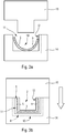
- a first material 10 is placed in a molding cavity 11, said molding cavity giving its shape to said first material at least in a first portion 12 of said molding cavity 11.
- the first material 10 is not already formed when it is installed in the molding cavity 11. This avoids the operations of prior shaping of the core of the part and has a solution whereby manufacturing tools are reduced compared to solutions using hot formed resin cores.
- the web 5 is cut beforehand in a contour of the part and said textile material is disposed in the molding cavity 11.
- the first material and therefore the fibers that it incorporates wife at least partially the shape of the molding cavity 11.
- the sheet of textile material 5 can be held in place, for following the operations, for example, by needles, not shown.
- said reinforcing fibers are previously disposed in the molding cavity and the binder is introduced into the molding cavity.
- the fibers thus conform to the shape of the molding cavity. They are held together for subsequent operations by the binder material.
- the fibers may be projected into the molding cavity, in particular by means of a spray gun.
- the binder material is then sprayed onto the fibers.
- a step is made to inject the second material 4 into the molding cavity 11 so as to overmold the core 2 with said second material 4, intended to give its rigidity to the workpiece 1.
- said first portion 12 of the molding cavity defines an area giving its general profile to the part, here in U.
- said molding cavity 11 comprises another area 13 for molding ribs 6 and / or interface areas.
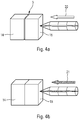
- the injection step is carried out, for example, by first introducing the second material into the molding cavity 5, according to the arrow 20, maintaining said molding cavity partially open.
- a second step closing said molding cavity 5 and subjecting said molding cavity to an increase in pressure. This may be done by injecting air into the mold cavity, according to the arrow marked 21, especially under high pressure.
- a mold comprising a die 14 and a punch 15 defining between them an air gap corresponding to said molding cavity 5.
- the gap is greater than 1 the thickness of the core 2 of the part 1 so that the second material 4 is provided on the entire surface of said core 2.
- a textile ply is cut with size reinforcing fibers, the ply is placed in a molding cavity, the second material is injected into the molding cavity and the workpiece is demolded.
- the reinforcing fibers are projected into the molding cavity, a binder is sprayed onto said fibers, the second material is injected into the molding cavity and the part is then demolded.
Description
La présente invention concerne une pièce de structure, notamment longeron de face avant de véhicule, et une face avant de véhicule, notamment automobile, comprenant une telle pièce. Elle concerne également un procédé de fabrication de ladite pièce de structure.The present invention relates to a structural part, in particular a front side member of a vehicle, and a front face of a vehicle, in particular an automobile, comprising such a part. It also relates to a method of manufacturing said structural part.
Une face avant de véhicule automobile est un élément structurel susceptible d'intégrer divers équipements du véhicule, tels que projecteurs, clignotants, avertisseur sonore, échangeur thermique ou module de refroidissement complet, etc. Formé en module, elle est destinée à être montée, pré équipée desdits éléments, sur le châssis du véhicule. Un tel mode de montage permet d'optimiser le processus de fabrication du véhicule en opérant en parallèle, d'une part, le montage du module de face avant et, d'autre part, le montage d'éléments, notamment le moteur, directement sur le châssis, le module de face avant étant ensuite rapporté d'un bloc sur le châssis.A front face of a motor vehicle is a structural element that can integrate various equipment of the vehicle, such as projectors, indicators, buzzer, heat exchanger or complete cooling module, etc. Formed in module, it is intended to be mounted, pre equipped with said elements, on the vehicle chassis. Such an assembly method makes it possible to optimize the manufacturing process of the vehicle by operating in parallel, on the one hand, the mounting of the front-face module and, on the other hand, the mounting of elements, in particular the motor, directly on the chassis, the front-panel module then being attached from a block to the chassis.
Il est ainsi connu des faces avant ou modules de faces avant comprenant une armature de support permettant la fixation des éléments d'équipement de la face avant. Outre leur fonction de support, lesdites armatures doivent de plus répondre à différentes contraintes d'absorption de chocs. Elles comprennent ainsi des pièces de structure telle que des longerons qui doivent présenter une rigidité suffisante.It is thus known front faces or front panel modules comprising a support frame for fixing the equipment elements of the front face. In addition to their support function, said frames must also meet different shock absorption constraints. They thus comprise structural parts such as longitudinal members which must have sufficient rigidity.
Les longerons employés aujourd'hui ont une structure en métal ou une structure hybride, combinant métal et matériau plastique. Dans les longerons en structure hybrides, le métal sert à donner sa forme à la pièce. Il est surmoulé du matériau plastique qui définit des nervures de renforcement et/ou des brides de fixation. Même si les longerons en structure hybride présentent un poids inférieur à ceux en métal, ils restent relativement lourds.The spars used today have a metal structure or a hybrid structure, combining metal and plastic material. In the hybrid structural spars, the metal serves to shape the workpiece. It is overmolded with the plastic material which defines reinforcing ribs and / or fixing flanges. Although the spars hybrid structure have a weight lower than metal, they remain relatively heavy.
Il est par ailleurs connu de former des pièces présentant une rigidité satisfaisante en employant des plaques de résine chargées de fibres. Lesdites plaques sont préalablement mises en forme par thermo formage puis surmoulées par un matériau plastique. En utilisant un tel matériau à la place du métal et en formant des nervures et/ou brides de fixation avec le matériau plastique, on pourrait obtenir des longerons présentant un poids inférieur aux longerons à structure hybride actuels. Le document
Bien qu'intéressante de ce point de vue, une telle solution présente cependant l'inconvénient de nécessiter un premier moule pour la mise en forme des plaques de résine et un moule supplémentaire pour le surmoulage de la matière plastique. Elle présente ainsi un coût élevé, à la fois en termes d'investissement et de mise en oeuvre. Cette solution nécessite de plus une opération de détourage de la matière, soit après mise en forme de la résine, soit après démoulage de la pièce. Un tel détourage augmente encore les coûts d'investissement et de mise en oeuvre. Il est aussi la source de chutes de matière qui grève le coût de revient de la pièce.Although interesting from this point of view, such a solution has the disadvantage of requiring a first mold for shaping the resin plates and an additional mold for overmolding the plastic material. It thus presents a high cost, both in terms of investment and implementation. This solution further requires a shaping operation of the material, either after shaping the resin or after demolding the workpiece. Such clipping further increases the costs of investment and implementation. It is also the source of material falls that strike the cost of the piece.
L'invention vise à améliorer la situation et propose à cette fin une pièce de structure, notamment longeron de face avant de véhicule, comprenant une âme en un premier matériau incorporant des fibres de renfort, ladite âme étant surmoulée d'un second matériau conférant sa rigidité à la pièce. L'âme est constituée d'une nappe de matériau textile incorporant les fibres de renforts. L'invention vient de l'analyse faite par le déposant selon laquelle l'intérêt des résines évoquées plus haut est la présence des fibres. En effet, ce sont elles qui confèrent la rigidité attendue pour des pièces de structure comme les longerons de face avant de véhicule. S'il est nécessaire d'employer un second matériau pour définir la pièce alors on peut conférer à ce second matériau le rôle de maintient en forme des fibres rempli, dans l'état de l'art, par la résine. On pourra ainsi simplifier le procédé de fabrication tout en obtenant des pièces présentant une rigidité satisfaisante et présentant un poids particulièrement faible.The aim of the invention is to improve the situation and proposes for this purpose a structural part, in particular a front side member of a vehicle, comprising a core made of a first material incorporating reinforcing fibers, said core being overmolded with a second material conferring its rigidity to the piece. The core consists of a sheet of textile material incorporating reinforcing fibers. The invention comes from the analysis made by the applicant that the interest of the resins mentioned above is the presence of the fibers. Indeed, it is they that confer the expected rigidity for structural parts such as the front side rails of the vehicle. If it is necessary to use a second material to define the part then this second material can be given the role of maintaining in the form of fibers filled, in the state of the art, by the resin. It will thus be possible to simplify the manufacturing process while obtaining parts having a satisfactory rigidity and having a particularly low weight.
Selon différents aspects de l'invention, qui pourront être pris ensemble ou séparément :
- le premier matériau est un matériau souple,
- les fibres de renfort sont disposées selon plusieurs directions,
- la pièce présente un profil général au niveau de l'âme et le second matériau définit des nervures et/ou des zones d'interface au niveau dudit profil général,
- ledit profil général est en U,
- le second matériau est prévu sur l'ensemble de la surface de l'âme de sorte que l'âme n'est plus visible extérieurement.
- the first material is a flexible material,
- the reinforcing fibers are arranged in several directions,
- the piece has a general profile at the core and the second material defines ribs and / or interface areas at said general profile,
- said general profile is in U,
- the second material is provided over the entire surface of the soul so that the soul is no longer visible externally.
L'invention concerne également une face avant de véhicule de véhicule, notamment automobile, comprenant une pièce de structure telle que définie plus haut.The invention also relates to a front end of a vehicle vehicle, in particular an automobile, comprising a structural part as defined above.
L'invention concerne encore un procédé de fabrication d'une pièce de structure, notamment longeron de face avant de véhicule, comprenant une âme en un premier matériau, incorporant des fibres de renfort, ladite âme étant surmoulée d'un second matériau, procédé dans lequel on dispose le premier matériau dans une cavité de moulage, ladite cavité de moulage donnant sa forme audit premier matériau au moins dans une première partie de ladite cavité de moulage. Le premier matériau est une nappe de matériau textile incorporant lesdites fibres de renfort, on découpe la nappe selon un contour de la pièce et on dispose ledit matériau textile dans la cavité de moulage. On dispose ainsi d'une solution permettant d'utiliser un seul outil de moulage plutôt que les deux outils nécessaires pour la fabrication de pièces employant des plaques de résines. On évitera de plus les opérations de détourage associées.The invention also relates to a method of manufacturing a structural part, in particular a front side member of a vehicle, comprising a core made of a first material, incorporating reinforcing fibers, said core being overmolded with a second material, which method is wherein the first material is disposed in a mold cavity, said mold cavity giving its shape to said first material at least in a first portion of said mold cavity. The first material is a web of textile material incorporating said reinforcing fibers, the web is cut in a contour of the workpiece and said textile material is placed in the molding cavity. There is thus a solution for using a single molding tool rather than the two tools required for the manufacture of parts employing resin plates. It will also avoid associated clipping operations.
Selon différents aspects de l'invention qui pourront être pris ensemble ou séparément :
- on réalise une étape d'injection du second matériau dans la cavité de moulage de façon à surmouler l'âme avec ledit second matériau,
- on effectue l'étape d'injection en introduisant le second matériau dans la cavité de moulage en maintenant ladite cavité de moulage partiellement ouverte puis on ferme ladite cavité de moulage et on soumet ladite cavité de moulage à une augmentation de pression,
- ladite première partie de la cavité de moulage définit une zone donnant son profil général à la pièce et ladite cavité de moulage comprend une autre zone pour le moulage de nervures et/ou zones d'interface.
- performing a step of injecting the second material into the molding cavity so as to overmold the core with said second material,
- the injection step is carried out by introducing the second material into the molding cavity while maintaining said molding cavity partially open and then closing said molding cavity and subjecting said molding cavity to a pressure increase,
- said first portion of the molding cavity defines an area giving its overall profile to the workpiece and said molding cavity comprises another area for molding ribs and / or interface areas.
Ledit procédé permet d'obtenir une pièce de structure telle décrite plus haut.Said method makes it possible to obtain a piece of structure as described above.
L'invention sera mieux comprise à la lecture de la description suivante accompagnée des dessins en annexe parmi lesquels :
- la
figure 1 illustre de façon schématique et partielle, en perspective, un exemple de pièce de structure selon l'invention, - la
figure 2 illustre de façon schématique, en perspective, une nappe de matériau employée dans la pièce de lafigure 1 , - la
figure 3a et 3b illustrent de façon schématique, en coupe transversale, un moule servant à l'obtention de la pièce de lafigure 1 , dans deux étapes successives de son procédé de fabrication, - les
figures 4a et 4b illustrent de façon schématique deux phases successives de l'une des étapes dudit procédé de fabrication.
- the
figure 1 illustrates schematically and partially, in perspective, an example of a structural part according to the invention, - the
figure 2 schematically illustrates, in perspective, a web of material used in the room of thefigure 1 , - the
Figure 3a and 3b schematically illustrate, in cross-section, a mold used to obtain the part of thefigure 1 in two successive stages of its manufacturing process, - the
Figures 4a and 4b schematically illustrate two successive phases of one of the steps of said manufacturing process.
Comme illustré à la
Ladite pièce comprend une âme 2 en un premier matériau incorporant des fibres de renfort 3. Ladite âme 2 est de plus surmoulée d'un second matériau 4 conférant sa rigidité à la pièce. On entend par là que, si la pièce 1 n'était constituée que de son âme 2, elle ne conserverait pas sa forme. C'est au contraire le second matériau 4 qui donne son maintien à la pièce.Said piece comprises a
On évite ainsi l'emploi d'une pièce préformée pour constituer l'âme 2. On peut en outre utiliser pour l'âme des matériaux légers permettant de diminuer le poids de la pièce 1 par rapport aux pièces hybrides métal plastique de l'état de l'art.This avoids the use of a preformed part to form the
Lesdites fibres 3 sont, par exemple, des fibres de verre ou des fibres de carbone, c'est-à-dire, des fibres suffisamment souples pour être mise en forme et présentant une résistance mécanique contribuant à renforcer la pièce.Said
Le second matériau est, par exemple, un matériau plastique. Il pourra s'agir, notamment, d'un polyamide tel que le matériau connu de l'homme du métier sous le nom de PA 6-6.The second material is, for example, a plastic material. It may be, in particular, a polyamide such as the material known to those skilled in the art under the name of PA 6-6.
Comme illustré à la
Selon une variante, non illustrée, l'âme est constituée d'un matériau liant incorporant lesdites fibres de renforts. Il s'agira, par exemple, d'un matériau polymérisable.According to a variant, not illustrated, the core is made of a binder material incorporating said reinforcing fibers. This will be, for example, a polymerizable material.
De manière avantageuse, les fibres sont disposées selon plusieurs directions. Il s'agira en particulier des directions selon lesquelles la pièce 1 est destinée à être sollicitée mécaniquement telle que, dans le cas de pièces allongées, de leur direction d'extension.Advantageously, the fibers are arranged in several directions. It will be in particular directions according to which the part 1 is intended to be mechanically stressed such that, in the case of elongated parts, their direction of extension.
Si l'on se reporte de nouveau à la
Le second matériau 4 est prévu, par exemple, sur l'ensemble de la surface de l'âme 2 de sorte que ladite âme 2 n'est plus visible extérieurement. On assure de la sorte une rigidité optimale de la pièce 1.The
Comme déjà évoqué, l'invention concerne également une face avant de véhicule, notamment automobile, comprenant une traverse supérieure formée d'une pièce de structure telle que décrite plus haut, notamment sous la forme d'une pièce de forme allongée.As already mentioned, the invention also relates to a front face of a vehicle, in particular an automobile, comprising an upper cross member formed of a structural part as described above, in particular in the form of an elongated piece.
Ladite face avant comprend, par exemple, une armature de support comprenant une traverse supérieure, destinée à définir une pièce horizontale, s'étendant sensiblement d'une aile à l'autre du véhicule équipé. Une telle armature pourra également comprendre un ou des jambages, rapportés au niveau des extrémités de ladite traverse supérieure. Lesdits jambages sont destinés à s'étendre verticalement. Ils pourront être reliés par une pièce horizontale basse. Ladite traverse supérieure, lesdits jambages et/ou ladite pièce horizontale basse pourront être constitués d'une pièce de structure 1 telle que définie plus haut.Said front face comprises, for example, a support frame comprising an upper cross member for defining a horizontal part, extending substantially from one wing to the other of the equipped vehicle. Such reinforcement may also include one or legs, reported at the ends of said upper cross. Said legs are intended to extend vertically. They can be connected by a low horizontal part. Said upper cross member, said legs and / or said low horizontal part may consist of a structural part 1 as defined above.
La face avant supporte, par exemple, différents éléments d'équipement, tels qu'une serrure de capot, des échangeurs de chaleurs, des projecteurs ou blocs optiques, des réservoirs de différents fluides, un bouclier avant et/ou autres. Tout ou partie desdits équipements sont fixés, notamment, à l'armature de support.The front face supports, for example, different items of equipment, such as a hood lock, heat exchangers, projectors or optical blocks, tanks of different fluids, a front bumper and / or others. All or part of said equipment is fixed, in particular, to the support frame.
L'invention concerne aussi d'ailleurs une telle armature de support, qui pourra être monobloc ou assemblée à partir de plusieurs pièces. Elle concerne encore un module de face avant, pré-monté et configuré pour un être monté en une seule opération sur le châssis du véhicule.The invention also relates to such a support frame, which can be monoblock or assembled from several pieces. It also relates to a front panel module, pre-assembled and configured to be mounted in a single operation on the vehicle chassis.
Telle qu'illustrés aux
Comme plus particulièrement illustré à la
On entend par là que le premier matériau 10 n'est pas déjà formé quand on l'installe dans la cavité de moulage 11. On évite ainsi les opérations de mise en forme préalable de l'âme de la pièce et on dispose d'une solution selon laquelle on réduit les outillages de fabrication par rapport à des solutions exploitant des âmes en résine formées à chaud.By this is meant that the
Dans le cas, correspondant à celui illustré, d'un premier matériau 10 formé d'une nappe de matériau textile 5 incorporant les fibres de renfort 3, on découpe préalablement la nappe 5 selon un contour de la pièce et on dispose ledit matériau textile dans la cavité de moulage 11. Par la souplesse du textile, le premier matériau et donc les fibres qu'il incorpore épouse au moins en partie la forme de la cavité de moulage 11. La nappe de matériau textile 5 pourra être maintenue en place, pour la suite des opérations, par exemple, par des aiguilles, non représentées.In the case, corresponding to that illustrated, of a
Selon une variante non illustrée dans laquelle ledit premier matériau est un liant, on dispose préalablement lesdites fibres de renfort dans la cavité de moulage et on introduit le liant dans la cavité de moulage. Les fibres épousent ainsi la forme de la cavité de moulage. Elles sont maintenues entre elles pour la suite des opérations par le matériau liant.According to a non-illustrated variant in which said first material is a binder, said reinforcing fibers are previously disposed in the molding cavity and the binder is introduced into the molding cavity. The fibers thus conform to the shape of the molding cavity. They are held together for subsequent operations by the binder material.
Selon cette variante, les fibres pourront être projetées dans la cavité de moulage, notamment à l'aide d'un pistolet. Le matériau liant est alors projeté sur les fibres.According to this variant, the fibers may be projected into the molding cavity, in particular by means of a spray gun. The binder material is then sprayed onto the fibers.
Dans ces différentes variantes, pour la suite des opérations, on réalise une étape d'injection du second matériau 4 dans la cavité de moulage 11 de façon à surmouler l'âme 2 avec ledit second matériau 4, destiné à donner sa rigidité à la pièce 1.In these different variants, for the following operations, a step is made to inject the
Selon un mode de réalisation avantageux, ladite première partie 12 de la cavité de moulage définit une zone donnant son profil général à la pièce, ici en U. Et ladite cavité de moulage 11 comprend une autre zone 13 pour le moulage de nervures 6 et/ou zones d'interface.According to an advantageous embodiment, said
Comme illustré aux
A titre d'exemple, on pourra employer un moule comprenant une matrice 14 et un poinçon 15 définissant entre eux un entrefer correspondant à ladite cavité de moulage 5. Au niveau de la première partie 12 de cette dernière, l'entrefer est supérieur à l'épaisseur de l'âme 2 de la pièce 1 de façon à ce que le second matériau 4 soit prévu sur l'ensemble de la surface de ladite âme 2.By way of example, it is possible to use a mold comprising a
Ainsi, selon une premier mode de réalisation, on découpe une nappe textile chargées de fibres de renfort à dimension, on met en place la nappe dans une cavité de moulage, on injecte le second matériau dans la cavité de moulage puis on démoule la pièce.Thus, according to a first embodiment, a textile ply is cut with size reinforcing fibers, the ply is placed in a molding cavity, the second material is injected into the molding cavity and the workpiece is demolded.
Selon un autre mode de réalisation, on projette les fibres de renfort dans la cavité de moulage, on projette un liant sur lesdites fibres, on injecte le second matériau dans la cavité de moulage puis on démoule la pièce.According to another embodiment, the reinforcing fibers are projected into the molding cavity, a binder is sprayed onto said fibers, the second material is injected into the molding cavity and the part is then demolded.
Cela étant, de tels modes de réalisation ne sont bien sûr pas limitatifs.However, such embodiments are of course not limiting.
Claims (11)
- Structural component (1), notably a vehicle front end side-member, comprising a core (2) made of a first material incorporating reinforcement fibres (3), the said core (2) being over-moulded with a second material (4) which provides the component with its rigidity, characterized in that the core (2) is constituted by a sheet (5) of textile material incorporating the reinforcement fibres (3).
- Component according to Claim 1, wherein the first material is a flexible material.
- Component according to either of the preceding claims, wherein the reinforcement fibres (3) are arranged according to a plurality of directions.
- Component according to any one of the preceding claims, wherein the component (1) has a general profile at the core (2), and the second material (4) defines ribs (6) and/or interface areas (7) at the said general profile.
- Component according to Claim 4, wherein the said general profile is in the form of a "U".
- Component according to any one of the preceding claims, wherein the second material (4) is provided on all of the surface of the core (2), such that the said core (2) is no longer visible from the exterior.
- Front end of a vehicle of a vehicle, in particular a motor vehicle, comprising a structural component (1) according to any one of the preceding claims.
- Method for production of a structural component (1), notably a vehicle front end side-member, comprising a core (2) made of a first material incorporating reinforcement fibres (3), the said core (2) being over-moulded with a second material (4), in which method the first material is arranged in a moulding cavity (11), the said moulding cavity (11) providing the said first material with its form at least in a first part (12) of the said moulding cavity (11), and wherein, with the first material being a sheet (5) of textile material incorporating the said reinforcement fibres (3), the sheet (5) is cut according to a contour of the component, and the said textile material (11) is arranged in the moulding cavity (11).
- Method according to Claim 8, wherein a step is carried out of injection of the second material (4) into the moulding cavity (11), such as to over-mould the core (2) with the said second material (4).
- Method according to Claim 9, wherein the injection step is carried out by introducing the second material (4) into the moulding cavity (11) whilst keeping the said moulding cavity (11) partially open, then the said moulding cavity (11) is closed, and the said moulding cavity (11) is subjected to a pressure increase.
- Method according to any one of the preceding claims, wherein the said first component (12) of the moulding cavity (11) defines an area which provides the component with its general profile, and wherein the said moulding cavity (11) comprises another area (13) for moulding of ribs (6) and/or interface areas (7).
Applications Claiming Priority (2)
| Application Number | Priority Date | Filing Date | Title |
|---|---|---|---|
| FR1158156A FR2979884B1 (en) | 2011-09-13 | 2011-09-13 | STRUCTURE PIECE, IN PARTICULAR FRONT FACE LENGTH OF VEHICLE, AND METHOD OF MANUFACTURING SUCH A PART |
| PCT/EP2012/067737 WO2013037774A1 (en) | 2011-09-13 | 2012-09-11 | Structural component, notably vehicle front end side-member, and method of manufacturing such a component |
Publications (2)
| Publication Number | Publication Date |
|---|---|
| EP2768721A1 EP2768721A1 (en) | 2014-08-27 |
| EP2768721B1 true EP2768721B1 (en) | 2017-07-19 |
Family
ID=46851469
Family Applications (1)
| Application Number | Title | Priority Date | Filing Date |
|---|---|---|---|
| EP12759100.6A Active EP2768721B1 (en) | 2011-09-13 | 2012-09-11 | Structural component, notably vehicle front end side-member, and method of manufacturing such a component |
Country Status (3)
| Country | Link |
|---|---|
| EP (1) | EP2768721B1 (en) |
| FR (1) | FR2979884B1 (en) |
| WO (1) | WO2013037774A1 (en) |
Family Cites Families (6)
| Publication number | Priority date | Publication date | Assignee | Title |
|---|---|---|---|---|
| EP1340668A3 (en) * | 2002-02-28 | 2003-09-17 | Bayer Ag | Lightweight structural element with outside ribbing |
| DE102004038893A1 (en) * | 2004-08-11 | 2006-02-23 | Volkswagen Ag | Front end module for a vehicle, in particular, a motor vehicle comprises a section which serves as a carrier of installed items, and is joined to a pedestrian protection beam and/or to a bumper cross beam |
| DE102005039469A1 (en) * | 2005-08-20 | 2007-02-22 | Hbpo Gmbh | Front end module with a mounting bracket with lower cross member |
| FR2890591B1 (en) * | 2005-09-12 | 2012-10-19 | Eads | METHOD FOR MANUFACTURING RTM COMPOSITE PIECE AND COMPOSITE PIECE OBTAINED ACCORDING TO SAID METHOD |
| CN101460299B (en) * | 2006-02-17 | 2016-03-09 | 威廉·罗杰斯 | The goods of composite construction and manufacture method thereof |
| DE102007041431A1 (en) * | 2007-08-29 | 2009-03-05 | Volkswagen Ag | Resin-transfer-molding method for manufacturing sliding door of motor vehicle, involves removing harden part from mixture, removing core from tool, and machining removed harden part for producing component |
-
2011
- 2011-09-13 FR FR1158156A patent/FR2979884B1/en active Active
-
2012
- 2012-09-11 WO PCT/EP2012/067737 patent/WO2013037774A1/en active Application Filing
- 2012-09-11 EP EP12759100.6A patent/EP2768721B1/en active Active
Non-Patent Citations (1)
| Title |
|---|
| None * |
Also Published As
| Publication number | Publication date |
|---|---|
| WO2013037774A1 (en) | 2013-03-21 |
| FR2979884A1 (en) | 2013-03-15 |
| EP2768721A1 (en) | 2014-08-27 |
| FR2979884B1 (en) | 2014-05-02 |
Similar Documents
| Publication | Publication Date | Title |
|---|---|---|
| EP0679565B1 (en) | Front end of an automobile | |
| FR3066466B1 (en) | STORAGE BIN FOR ASSEMBLY ON A BODY STRUCTURE OF A MOTOR VEHICLE. | |
| FR2829734A1 (en) | Motor vehicle fender has two shock absorbers of synthetic materials, different from material of cross beam | |
| FR2866830A1 (en) | Motor vehicle fender of synthetic material is made with metal insert to receive towing ring | |
| FR2702432A1 (en) | Bumper, especially for a motor vehicle | |
| CN103144561A (en) | Seat armrest frame | |
| FR3050705A1 (en) | VEHICLE WITH LATERAL REINFORCEMENTS AT THE BOTTOM | |
| FR2999468A1 (en) | COMPRESSION MOLDING BODY WITH IMPROVED SEALING | |
| EP1718515B1 (en) | Method for producing a vehicle floor comprising a synthetic layer of material | |
| EP0847912B1 (en) | Impact absorbing fairing for the underside of an automobile | |
| EP2768721B1 (en) | Structural component, notably vehicle front end side-member, and method of manufacturing such a component | |
| US20210284250A1 (en) | Hybrid material vehicle panel and methods of making the same | |
| FR2836434A1 (en) | A bumper assembly for the front end of a vehicle comprising a rigid metal or plastic profile and a bumper, between which are horizontal or inclined plastic laminations acting as shock absorbers in pedestrian collisions | |
| FR2975937A1 (en) | Method for injection molding front face of car, involves injecting one of two plastic materials into one of molding compartments, retracting lock to join molding compartments together, and injecting other material into other compartment | |
| FR2898855A1 (en) | Front face for motor vehicle, has metallic insert and tube made by hydroforming metallic material, and plastic parts molded on insert and tube respectively, where parts are molded simultaneously with same plastic material | |
| FR2943317A1 (en) | Fabricating an air inlet lip for aeronautical engine nacelle comprising two quarters, comprises embossing a sheet to impart circular arc profile, bending a plate to impart a circular arc profile, and friction stir welding the curved plate | |
| EP1972527B1 (en) | Reinforced engine protection shielding for a vehicle | |
| FR2995865A1 (en) | Lining for interior skin of side door of car, has upper lining part provided with structural parts in bamboo so as to make structural lining, and to form profile so as to ensure resistance to longitudinal compressive forces | |
| EP3154842B1 (en) | Front portion of the structure of a motor vehicle | |
| FR3014401A1 (en) | FRONT APRON BY COMPOSITE PART ASSEMBLY | |
| EP2368786B1 (en) | Technical front-end including a metal insert and a part made of plastic material | |
| FR2874889A1 (en) | Front technical face for motor vehicle frame is made from sheet metal core and over-moulded plastic components | |
| FR3053305A1 (en) | STRUCTURE FOR FRONT PANEL OF MOTOR VEHICLE | |
| FR3076804A1 (en) | STRUCTURAL PIECE FOR A VEHICLE WHITE BODY AND METHOD OF MANUFACTURING THE SAME | |
| EP2113447A1 (en) | Automobile structure, method for manufacturing same, and vehicle comprising such a structure. |
Legal Events
| Date | Code | Title | Description |
|---|---|---|---|
| PUAI | Public reference made under article 153(3) epc to a published international application that has entered the european phase |
Free format text: ORIGINAL CODE: 0009012 |
|
| 17P | Request for examination filed |
Effective date: 20140625 |
|
| AK | Designated contracting states |
Kind code of ref document: A1 Designated state(s): AL AT BE BG CH CY CZ DE DK EE ES FI FR GB GR HR HU IE IS IT LI LT LU LV MC MK MT NL NO PL PT RO RS SE SI SK SM TR |
|
| DAX | Request for extension of the european patent (deleted) | ||
| 17Q | First examination report despatched |
Effective date: 20160905 |
|
| GRAP | Despatch of communication of intention to grant a patent |
Free format text: ORIGINAL CODE: EPIDOSNIGR1 |
|
| INTG | Intention to grant announced |
Effective date: 20170407 |
|
| RAP1 | Party data changed (applicant data changed or rights of an application transferred) |
Owner name: VALEO SYSTEMES THERMIQUES |
|
| GRAS | Grant fee paid |
Free format text: ORIGINAL CODE: EPIDOSNIGR3 |
|
| GRAA | (expected) grant |
Free format text: ORIGINAL CODE: 0009210 |
|
| AK | Designated contracting states |
Kind code of ref document: B1 Designated state(s): AL AT BE BG CH CY CZ DE DK EE ES FI FR GB GR HR HU IE IS IT LI LT LU LV MC MK MT NL NO PL PT RO RS SE SI SK SM TR |
|
| REG | Reference to a national code |
Ref country code: GB Ref legal event code: FG4D Free format text: NOT ENGLISH |
|
| REG | Reference to a national code |
Ref country code: CH Ref legal event code: EP |
|
| REG | Reference to a national code |
Ref country code: IE Ref legal event code: FG4D Free format text: LANGUAGE OF EP DOCUMENT: FRENCH |
|
| REG | Reference to a national code |
Ref country code: AT Ref legal event code: REF Ref document number: 910102 Country of ref document: AT Kind code of ref document: T Effective date: 20170815 |
|
| REG | Reference to a national code |
Ref country code: DE Ref legal event code: R096 Ref document number: 602012034732 Country of ref document: DE |
|
| REG | Reference to a national code |
Ref country code: FR Ref legal event code: PLFP Year of fee payment: 6 |
|
| PGFP | Annual fee paid to national office [announced via postgrant information from national office to epo] |
Ref country code: FR Payment date: 20170929 Year of fee payment: 6 |
|
| REG | Reference to a national code |
Ref country code: NL Ref legal event code: MP Effective date: 20170719 |
|
| REG | Reference to a national code |
Ref country code: LT Ref legal event code: MG4D |
|
| REG | Reference to a national code |
Ref country code: AT Ref legal event code: MK05 Ref document number: 910102 Country of ref document: AT Kind code of ref document: T Effective date: 20170719 |
|
| PG25 | Lapsed in a contracting state [announced via postgrant information from national office to epo] |
Ref country code: HR Free format text: LAPSE BECAUSE OF FAILURE TO SUBMIT A TRANSLATION OF THE DESCRIPTION OR TO PAY THE FEE WITHIN THE PRESCRIBED TIME-LIMIT Effective date: 20170719 Ref country code: FI Free format text: LAPSE BECAUSE OF FAILURE TO SUBMIT A TRANSLATION OF THE DESCRIPTION OR TO PAY THE FEE WITHIN THE PRESCRIBED TIME-LIMIT Effective date: 20170719 Ref country code: AT Free format text: LAPSE BECAUSE OF FAILURE TO SUBMIT A TRANSLATION OF THE DESCRIPTION OR TO PAY THE FEE WITHIN THE PRESCRIBED TIME-LIMIT Effective date: 20170719 Ref country code: SE Free format text: LAPSE BECAUSE OF FAILURE TO SUBMIT A TRANSLATION OF THE DESCRIPTION OR TO PAY THE FEE WITHIN THE PRESCRIBED TIME-LIMIT Effective date: 20170719 Ref country code: NO Free format text: LAPSE BECAUSE OF FAILURE TO SUBMIT A TRANSLATION OF THE DESCRIPTION OR TO PAY THE FEE WITHIN THE PRESCRIBED TIME-LIMIT Effective date: 20171019 Ref country code: LT Free format text: LAPSE BECAUSE OF FAILURE TO SUBMIT A TRANSLATION OF THE DESCRIPTION OR TO PAY THE FEE WITHIN THE PRESCRIBED TIME-LIMIT Effective date: 20170719 Ref country code: NL Free format text: LAPSE BECAUSE OF FAILURE TO SUBMIT A TRANSLATION OF THE DESCRIPTION OR TO PAY THE FEE WITHIN THE PRESCRIBED TIME-LIMIT Effective date: 20170719 |
|
| PG25 | Lapsed in a contracting state [announced via postgrant information from national office to epo] |
Ref country code: LV Free format text: LAPSE BECAUSE OF FAILURE TO SUBMIT A TRANSLATION OF THE DESCRIPTION OR TO PAY THE FEE WITHIN THE PRESCRIBED TIME-LIMIT Effective date: 20170719 Ref country code: BG Free format text: LAPSE BECAUSE OF FAILURE TO SUBMIT A TRANSLATION OF THE DESCRIPTION OR TO PAY THE FEE WITHIN THE PRESCRIBED TIME-LIMIT Effective date: 20171019 Ref country code: RS Free format text: LAPSE BECAUSE OF FAILURE TO SUBMIT A TRANSLATION OF THE DESCRIPTION OR TO PAY THE FEE WITHIN THE PRESCRIBED TIME-LIMIT Effective date: 20170719 Ref country code: PL Free format text: LAPSE BECAUSE OF FAILURE TO SUBMIT A TRANSLATION OF THE DESCRIPTION OR TO PAY THE FEE WITHIN THE PRESCRIBED TIME-LIMIT Effective date: 20170719 Ref country code: GR Free format text: LAPSE BECAUSE OF FAILURE TO SUBMIT A TRANSLATION OF THE DESCRIPTION OR TO PAY THE FEE WITHIN THE PRESCRIBED TIME-LIMIT Effective date: 20171020 Ref country code: IS Free format text: LAPSE BECAUSE OF FAILURE TO SUBMIT A TRANSLATION OF THE DESCRIPTION OR TO PAY THE FEE WITHIN THE PRESCRIBED TIME-LIMIT Effective date: 20171119 Ref country code: ES Free format text: LAPSE BECAUSE OF FAILURE TO SUBMIT A TRANSLATION OF THE DESCRIPTION OR TO PAY THE FEE WITHIN THE PRESCRIBED TIME-LIMIT Effective date: 20170719 |
|
| PGFP | Annual fee paid to national office [announced via postgrant information from national office to epo] |
Ref country code: ES Payment date: 20171016 Year of fee payment: 6 |
|
| REG | Reference to a national code |
Ref country code: DE Ref legal event code: R097 Ref document number: 602012034732 Country of ref document: DE |
|
| PG25 | Lapsed in a contracting state [announced via postgrant information from national office to epo] |
Ref country code: DK Free format text: LAPSE BECAUSE OF FAILURE TO SUBMIT A TRANSLATION OF THE DESCRIPTION OR TO PAY THE FEE WITHIN THE PRESCRIBED TIME-LIMIT Effective date: 20170719 Ref country code: RO Free format text: LAPSE BECAUSE OF FAILURE TO SUBMIT A TRANSLATION OF THE DESCRIPTION OR TO PAY THE FEE WITHIN THE PRESCRIBED TIME-LIMIT Effective date: 20170719 Ref country code: CZ Free format text: LAPSE BECAUSE OF FAILURE TO SUBMIT A TRANSLATION OF THE DESCRIPTION OR TO PAY THE FEE WITHIN THE PRESCRIBED TIME-LIMIT Effective date: 20170719 |
|
| REG | Reference to a national code |
Ref country code: CH Ref legal event code: PL |
|
| PLBE | No opposition filed within time limit |
Free format text: ORIGINAL CODE: 0009261 |
|
| STAA | Information on the status of an ep patent application or granted ep patent |
Free format text: STATUS: NO OPPOSITION FILED WITHIN TIME LIMIT |
|
| PG25 | Lapsed in a contracting state [announced via postgrant information from national office to epo] |
Ref country code: EE Free format text: LAPSE BECAUSE OF FAILURE TO SUBMIT A TRANSLATION OF THE DESCRIPTION OR TO PAY THE FEE WITHIN THE PRESCRIBED TIME-LIMIT Effective date: 20170719 Ref country code: SM Free format text: LAPSE BECAUSE OF FAILURE TO SUBMIT A TRANSLATION OF THE DESCRIPTION OR TO PAY THE FEE WITHIN THE PRESCRIBED TIME-LIMIT Effective date: 20170719 Ref country code: MC Free format text: LAPSE BECAUSE OF FAILURE TO SUBMIT A TRANSLATION OF THE DESCRIPTION OR TO PAY THE FEE WITHIN THE PRESCRIBED TIME-LIMIT Effective date: 20170719 Ref country code: SK Free format text: LAPSE BECAUSE OF FAILURE TO SUBMIT A TRANSLATION OF THE DESCRIPTION OR TO PAY THE FEE WITHIN THE PRESCRIBED TIME-LIMIT Effective date: 20170719 Ref country code: IT Free format text: LAPSE BECAUSE OF FAILURE TO SUBMIT A TRANSLATION OF THE DESCRIPTION OR TO PAY THE FEE WITHIN THE PRESCRIBED TIME-LIMIT Effective date: 20170719 |
|
| 26N | No opposition filed |
Effective date: 20180420 |
|
| GBPC | Gb: european patent ceased through non-payment of renewal fee |
Effective date: 20171019 |
|
| REG | Reference to a national code |
Ref country code: IE Ref legal event code: MM4A |
|
| REG | Reference to a national code |
Ref country code: BE Ref legal event code: MM Effective date: 20170930 |
|
| PG25 | Lapsed in a contracting state [announced via postgrant information from national office to epo] |
Ref country code: LU Free format text: LAPSE BECAUSE OF NON-PAYMENT OF DUE FEES Effective date: 20170911 |
|
| PG25 | Lapsed in a contracting state [announced via postgrant information from national office to epo] |
Ref country code: IE Free format text: LAPSE BECAUSE OF NON-PAYMENT OF DUE FEES Effective date: 20170911 Ref country code: GB Free format text: LAPSE BECAUSE OF NON-PAYMENT OF DUE FEES Effective date: 20171019 Ref country code: LI Free format text: LAPSE BECAUSE OF NON-PAYMENT OF DUE FEES Effective date: 20170930 Ref country code: CH Free format text: LAPSE BECAUSE OF NON-PAYMENT OF DUE FEES Effective date: 20170930 |
|
| PG25 | Lapsed in a contracting state [announced via postgrant information from national office to epo] |
Ref country code: SI Free format text: LAPSE BECAUSE OF FAILURE TO SUBMIT A TRANSLATION OF THE DESCRIPTION OR TO PAY THE FEE WITHIN THE PRESCRIBED TIME-LIMIT Effective date: 20170719 Ref country code: BE Free format text: LAPSE BECAUSE OF NON-PAYMENT OF DUE FEES Effective date: 20170930 |
|
| PG25 | Lapsed in a contracting state [announced via postgrant information from national office to epo] |
Ref country code: MT Free format text: LAPSE BECAUSE OF FAILURE TO SUBMIT A TRANSLATION OF THE DESCRIPTION OR TO PAY THE FEE WITHIN THE PRESCRIBED TIME-LIMIT Effective date: 20170719 |
|
| PG25 | Lapsed in a contracting state [announced via postgrant information from national office to epo] |
Ref country code: HU Free format text: LAPSE BECAUSE OF FAILURE TO SUBMIT A TRANSLATION OF THE DESCRIPTION OR TO PAY THE FEE WITHIN THE PRESCRIBED TIME-LIMIT; INVALID AB INITIO Effective date: 20120911 |
|
| PG25 | Lapsed in a contracting state [announced via postgrant information from national office to epo] |
Ref country code: FR Free format text: LAPSE BECAUSE OF NON-PAYMENT OF DUE FEES Effective date: 20180930 |
|
| PG25 | Lapsed in a contracting state [announced via postgrant information from national office to epo] |
Ref country code: CY Free format text: LAPSE BECAUSE OF FAILURE TO SUBMIT A TRANSLATION OF THE DESCRIPTION OR TO PAY THE FEE WITHIN THE PRESCRIBED TIME-LIMIT Effective date: 20170719 |
|
| PG25 | Lapsed in a contracting state [announced via postgrant information from national office to epo] |
Ref country code: MK Free format text: LAPSE BECAUSE OF FAILURE TO SUBMIT A TRANSLATION OF THE DESCRIPTION OR TO PAY THE FEE WITHIN THE PRESCRIBED TIME-LIMIT Effective date: 20170719 |
|
| PG25 | Lapsed in a contracting state [announced via postgrant information from national office to epo] |
Ref country code: TR Free format text: LAPSE BECAUSE OF FAILURE TO SUBMIT A TRANSLATION OF THE DESCRIPTION OR TO PAY THE FEE WITHIN THE PRESCRIBED TIME-LIMIT Effective date: 20170719 |
|
| PG25 | Lapsed in a contracting state [announced via postgrant information from national office to epo] |
Ref country code: PT Free format text: LAPSE BECAUSE OF FAILURE TO SUBMIT A TRANSLATION OF THE DESCRIPTION OR TO PAY THE FEE WITHIN THE PRESCRIBED TIME-LIMIT Effective date: 20170719 |
|
| PG25 | Lapsed in a contracting state [announced via postgrant information from national office to epo] |
Ref country code: AL Free format text: LAPSE BECAUSE OF FAILURE TO SUBMIT A TRANSLATION OF THE DESCRIPTION OR TO PAY THE FEE WITHIN THE PRESCRIBED TIME-LIMIT Effective date: 20170719 |
|
| PGFP | Annual fee paid to national office [announced via postgrant information from national office to epo] |
Ref country code: ES Payment date: 20221001 Year of fee payment: 6 |
|
| P01 | Opt-out of the competence of the unified patent court (upc) registered |
Effective date: 20230528 |
|
| PGFP | Annual fee paid to national office [announced via postgrant information from national office to epo] |
Ref country code: DE Payment date: 20230911 Year of fee payment: 12 |