EP2768245A1 - Magnet mount assembly for a loudspeaker and method for disassembling a magnet mount assembly - Google Patents
Magnet mount assembly for a loudspeaker and method for disassembling a magnet mount assembly Download PDFInfo
- Publication number
- EP2768245A1 EP2768245A1 EP13155032.9A EP13155032A EP2768245A1 EP 2768245 A1 EP2768245 A1 EP 2768245A1 EP 13155032 A EP13155032 A EP 13155032A EP 2768245 A1 EP2768245 A1 EP 2768245A1
- Authority
- EP
- European Patent Office
- Prior art keywords
- pedestal
- mount assembly
- magnet
- support
- aperture
- Prior art date
- Legal status (The legal status is an assumption and is not a legal conclusion. Google has not performed a legal analysis and makes no representation as to the accuracy of the status listed.)
- Withdrawn
Links
Images


Classifications
-
- H—ELECTRICITY
- H04—ELECTRIC COMMUNICATION TECHNIQUE
- H04R—LOUDSPEAKERS, MICROPHONES, GRAMOPHONE PICK-UPS OR LIKE ACOUSTIC ELECTROMECHANICAL TRANSDUCERS; DEAF-AID SETS; PUBLIC ADDRESS SYSTEMS
- H04R9/00—Transducers of moving-coil, moving-strip, or moving-wire type
- H04R9/02—Details
- H04R9/025—Magnetic circuit
-
- H—ELECTRICITY
- H04—ELECTRIC COMMUNICATION TECHNIQUE
- H04R—LOUDSPEAKERS, MICROPHONES, GRAMOPHONE PICK-UPS OR LIKE ACOUSTIC ELECTROMECHANICAL TRANSDUCERS; DEAF-AID SETS; PUBLIC ADDRESS SYSTEMS
- H04R2209/00—Details of transducers of the moving-coil, moving-strip, or moving-wire type covered by H04R9/00 but not provided for in any of its subgroups
- H04R2209/024—Manufacturing aspects of the magnetic circuit of loudspeaker or microphone transducers
Definitions
- the embodiments described herein relate to a magnet mount assembly for a loudspeaker, a loudspeaker and methods for assembling and disassembling a magnet mount assembly.
- a transducer is a device that converts one form of an input signal into another form.
- Loudspeakers are one example of the transducer and convert electrical signals into sound.
- Loudspeakers include a diaphragm, a voice coil and a magnet.
- the voice coil is connected to the diaphragm and arranged in an air gap, in which the magnet generates magnetic flux.
- a magnetic field is induced which interacts with the magnetic flux in air gap generated by the magnet. This interaction causes the voice coil to oscillate, which in turn causes the diaphragm to move and sound to be generated.
- the magnet is part of a magnet structure which may include, among other components, one or more magnets, a core cap and a shell pot.
- the shell pot may provide a housing which contains the magnet and the core.
- the shell pot may have a cylindrical shape with a base which defines a hollow interior.
- the magnet may be disposed on the base of the shell pot and the core cap may be mounted on the magnet or between two magnets.
- adhesives may be used to secure the position of the magnet, the core cap and the shell pot with respect to one another. Under some circumstances, it may be desirable to disassemble the magnet structure, in order to remove or replace one or more of the components for example.
- a magnet mount assembly for a loudspeaker which includes a support comprising a receiver portion and a pedestal, the receiver portion being configured to receive a magnet of the loudspeaker, and a shell pot having a base and a peripheral wall protruding from the base, the base including an aperture.
- the shell pot is configured to receive the support and the pedestal is insertable into the aperture to detachedly attach the support to the shell pot.
- a method for disassembling a magnet mount assembly for a loudspeaker including a shell pot having a base and a peripheral wall protruding from the base, the base including an aperture, and a support including a receiver portion and a pedestal, the receiver portion retaining a magnet of the loudspeaker.
- the receiver portion is positioned in the shell pot.
- the pedestal is positioned in the aperture and detachedly attaches the support to the shell pot.
- the method includes applying a force to the pedestal in a direction generally parallel to a longitudinal axis of the aperture, detaching the pedestal from the aperture, and removing the support from the shell pot.
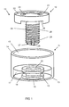
- FIG. 1 illustrates a perspective view of a magnet mount assembly 10 according to a first embodiment in a partially disassembled position.
- the magnet mount assembly 10 includes a shell pot 11 and a support 12.
- the shell pot 11 includes a base 13 and a peripheral wall 14 defining a hollow interior 15 for receiving a magnet.
- the shell pot 11 further includes an aperture 16 in the base 13.
- the shell pot 11 has a generally cylindrical form and the aperture 16 is positioned coaxially with respect to the peripheral wall 14.
- the base 13 of the shell pot 11 includes a raised pedestal portion 17 in which the aperture 16 is positioned so that the aperture 16 is defined by inner walls 18 providing an elongated aperture.
- the magnet mount assembly 10 further includes a resilient member 19 which is arranged on the inner walls 18 of the aperture 16.
- the resilient member 19 defines a cylindrical aperture 20 which extends through the raised portion pedestal portion 17 of the base 13.
- the resilient member 19 comprises a resilient grommet.
- the support 12 includes a receiver portion 21 having a recess 22 in an upper surface 23, the recess 22 being configured to receive a magnet.
- the support 12 further includes a pedestal 24 which has a generally cylindrical form with a longitudinal axis. The pedestal 24 extends from a lower surface 25 of the support 12. In this particular embodiment, the pedestal 24 includes a protruding structure on its outer surface in the form of a coarse thread 26.
- the support 12 is configured to be accommodated within the hollow interior 15 of the shell pot 11 and the pedestal 24 is configured to mechanically engage the resilient member 19 when the pedestal 24 is inserted in the aperture 20 in order to detachedly attach the support 12 to the shell pot 11.
- the outer diameter is of the pedestal 24 is slightly larger than the diameter of the aperture 20.
- the support 12 and the shell pot 11 comprise a ferromagnetic material such as steel and the resilient member 19 may comprise rubber.
- a lower surface 27 of the pedestal 24 includes an engagement portion 28 which is configured to engage a non-illustrated magnet removal tool.
- the engagement portion 28 comprises an indentation 29.
- the magnet mount assembly may be assembled by inserting the pedestal 24 of the support 12 into the aperture 20 of the resilient member 19 which is itself retained in the aperture 16 of the base 13 of the shell pot 11.
- the resilient member is resiliently deformed by the pedestal as the diameter of the aperture 20 is slightly smaller than the diameter of the pedestal 24.
- the resilient member 19 exerts a force on the pedestal 24 and the pedestal 24 is retained within the aperture 20 and detachedly attached to the base 13, whereby the support 12 is detachedly attached to the shell pot 11.
- the pedestal 24 includes an outer surface with a coarse thread 26.
- the pedestal may be detachedly attached to the resilient member 19 by screwing the pedestal 24 into the aperture 20 of the resilient member 19.
- the lower surface 27 of pedestal 24 is positioned in the aperture 20 which extends through the base 13 of the shell pot 11.
- the indentation 29 is accessible from outside of the shell pot 11 via the aperture 20.
- a magnet removal tool may be inserted into the indentation 29 in order to apply force to the pedestal 24 in a direction perpendicular to the base 13 of the shell pot 11 and parallel to the longitudinal axis of the pedestal 24.
- the applied force is greater than the force between the pedestal 24 and the resilient member 19, the pedestal 24 is caused to move with respect to the resilient member 19, thus detaching the support 12 from the shell pot 11 and allowing the support structure 12 to be removed from the shell pot 11.
- the outer surface of the pedestal 24 includes a coarse thread 26.
- the pedestal 24 may be removed from the aperture 20 of the resilient member 19 by a screwing action.
- a magnet In the assembled position of the magnet mount assembly, a magnet is positioned in the recess 22 and may be attached to the recess 22 by a layer of adhesive. Therefore, by removing the support 12 from the shell pot 11, the magnet is removed from within the hollow interior 15 of the shell pot 11.
- the magnet is attached to the support 12, which is detachedly attached to the shell pot 11, rather than being directly fixed to the shell pot 11, for example by an adhesive.
- This arrangement enables the magnet to be easily removed from the shell pot 11. This is useful in order to be able to recycle the magnets, for example.
- the magnet may be a rare earth-based magnet such as a neodymium-iron-boron-based magnet.
- the cost of the rare earth elements, such as neodymium has risen significantly in recent years. Therefore, the magnet mount assembly 10 may be used to facilitate the removal of a magnet from the shell pot 11 in order to enable the rare earth elements to be extracted from the magnet.
- FIG. 2 illustrates a cross-sectional view of the support 12 of the magnet mount assembly 10 and FIG. 3 illustrates a top view of the support 12 illustrated in FIG. 2 .
- the support 12 includes two through holes 30 positioned towards the periphery of the recess 22 on opposing sides of the recess 22.
- the through holes 30 provide fixing holes for a press to unlock mechanism.
- FIG. 4 illustrates a cross-sectional view of the shell pot 11 and the support 12 of the magnet mount assembly 10
- FIG. 5 illustrates a cross-sectional view of the support 12 and the shell pot 11 including the resilient member 19 positioned in the aperture 16 of the base 13 of the shell pot 11.
- the aperture 16 in the base 13 of the shell pot 11 comprises an inwardly protruding portion 31 which, in this particular embodiment has a ring shape.
- the inwardly protruding portion 31 provides a retainer for retaining the resilient member 19 within the aperture 16.
- FIG. 6a illustrates a cross-sectional view
- FIG. 6b illustrates a side view of the resilient member 19.
- the resilient member 19 includes a groove 32 in its outer surface which is configured to engage the protruding portion 31 of the aperture 16 so that the resilient member 19 is retained within the aperture 16 of the base 13.
- the resilient member 19 provides an aperture 20 having a generally cylindrical form with a diameter which is slightly smaller than the outer diameter of the pedestal 24 in order to allow mechanical engagement between the pedestal 24 and the resilient member 19 and to detachedly attach the support 12 to the shell pot 11.
- the lower surface 25 of the receiver portion 21 of the support 12 also comprises a recessed portion 33 in the form of a ring which surrounds the base of the pedestal 24.
- the resilient member 19 has dimensions such that a portion 34 protrudes above the upper surface 35 of the raised pedestal portion 17 of the shell pot 11. This protruding portion 34 of the resilient member 19 is able to mate with the recessed portion 33 in the lower surface 25 of the receiver portion 21 after insertion of the pedestal 24 into the aperture 20 of the resilient member 19 to provide a resilient connection between the support 12 and the shell pot 11.
- FIG. 7 illustrates a magnet structure 40 of a loudspeaker.
- the magnet structure 40 includes the support 12 with the receiver portion 21 and the pedestal 24, the resilient member 19 in the form of a rubber grommet, a first magnet 41 arranged in the recess 22 of the support 12, a core cap 42 positioned on the first magnet 41 and a second magnet 43 positioned on the core cap 42.
- the magnets 41, 43 and the core cap 42 may have an interlocking structure or may be mounted to one another by adhesive.
- the resilient member 19 is illustrated in the assembled position of the magnetic mount assembly 10.
- the protruding portion 34 of the resilient member 19 is positioned within the recess portion 33 on the lower surface 25 of the support 12 and provides an additional mechanical interlocking between the support 12 and the resilient member 19.
- the lower surface 25 of the receiver portion is, in the assembled position, spaced at a slight distance from the upper surface 35 of the raised pedestal portion 17 of the base 13 of the shell pot 11.
- the first magnet 41, the core cap 42 and the second magnet 43 are supported by support 12 and may be detached from the shell pot 11 along with the support 12 by applying force to the lower surface 27 of the pedestal 24, for example by a screwing action if the outer surface of the pedestal includes a thread.
- a loudspeaker including a magnet mount assembly includes a magnet, a support comprising a receiver portion and a pedestal, the receiver portion retaining the magnet, and a shell pot having a base and a peripheral wall protruding from the base, the base comprising an aperture.
- the support is positioned within the shell pot and the pedestal is positioned in the aperture and detachedly attaching the support to the shell pot.
- a method for assembling a magnet mount assembly for a loudspeaker includes providing a support comprising a receiver portion and a pedestal, the receiver portion being configured to receive a magnet of the loudspeaker, providing a shell pot having a base including an aperture, the shell pot being configured to receive the support, and inserting the pedestal into the aperture to detachedly attach the support to the shell pot.
Abstract
A magnet mount assembly for a loudspeaker includes a support comprising a receiver portion and a pedestal, the receiver portion being configured to receive a magnet of the loudspeaker, and a shell pot having a base and a peripheral wall protruding from the base, the base including an aperture. The shell pot is configured to receive the support and the pedestal is insertable into the aperture to detachedly attach the support to the shell pot.
Description
- The embodiments described herein relate to a magnet mount assembly for a loudspeaker, a loudspeaker and methods for assembling and disassembling a magnet mount assembly.
- A transducer is a device that converts one form of an input signal into another form. Loudspeakers are one example of the transducer and convert electrical signals into sound. Loudspeakers include a diaphragm, a voice coil and a magnet. The voice coil is connected to the diaphragm and arranged in an air gap, in which the magnet generates magnetic flux. As input current flows through the voice coil, a magnetic field is induced which interacts with the magnetic flux in air gap generated by the magnet. This interaction causes the voice coil to oscillate, which in turn causes the diaphragm to move and sound to be generated.
- The magnet is part of a magnet structure which may include, among other components, one or more magnets, a core cap and a shell pot. The shell pot may provide a housing which contains the magnet and the core. For example, the shell pot may have a cylindrical shape with a base which defines a hollow interior. The magnet may be disposed on the base of the shell pot and the core cap may be mounted on the magnet or between two magnets.
- During manufacture of the magnet structure, adhesives may be used to secure the position of the magnet, the core cap and the shell pot with respect to one another. Under some circumstances, it may be desirable to disassemble the magnet structure, in order to remove or replace one or more of the components for example.
- A magnet mount assembly for a loudspeaker is described which includes a support comprising a receiver portion and a pedestal, the receiver portion being configured to receive a magnet of the loudspeaker, and a shell pot having a base and a peripheral wall protruding from the base, the base including an aperture. The shell pot is configured to receive the support and the pedestal is insertable into the aperture to detachedly attach the support to the shell pot.
- A method for disassembling a magnet mount assembly for a loudspeaker is described herein, the magnet mount assembly including a shell pot having a base and a peripheral wall protruding from the base, the base including an aperture, and a support including a receiver portion and a pedestal, the receiver portion retaining a magnet of the loudspeaker. The receiver portion is positioned in the shell pot. The pedestal is positioned in the aperture and detachedly attaches the support to the shell pot. The method includes applying a force to the pedestal in a direction generally parallel to a longitudinal axis of the aperture, detaching the pedestal from the aperture, and removing the support from the shell pot.
- Other systems, methods, features and advantages will be, or will become, apparent to one with skilled in the art upon examination of the following figures and detailed description. It is intended that all such additional systems, methods, features and advantages be included within this description, be within the scope of the invention, and be protected by the following claims.
- The invention can be better understood with reference to the following drawings and description. The components in the figures are not necessarily to scale, emphasis instead being placed upon illustrating the principles of the invention. Moreover, in the figures, like reference numerals designate corresponding parts throughout the different views.
-
FIG. 1 illustrates a perspective view of a magnet mount assembly according to a first embodiment. -
FIG. 2 illustrates a cross-sectional view of a support of the magnet mount assembly. -
FIG. 3 illustrates a top view of the support illustrated inFIG. 2 . -
FIG. 4 illustrates a cross-sectional view of the support and a shell pot of the magnet mount assembly. -
FIG. 5 illustrates a cross-sectional view of the support and the shell pot including a resilient grommet. -
FIG. 6a illustrates a cross-sectional view of the resilient grommet. -
FIG. 6b illustrates a side view of the resilient grommet. -
FIG. 7 illustrates a magnet structure for a loudspeaker. -
FIG. 1 illustrates a perspective view of amagnet mount assembly 10 according to a first embodiment in a partially disassembled position. - The
magnet mount assembly 10 includes ashell pot 11 and asupport 12. Theshell pot 11 includes abase 13 and aperipheral wall 14 defining ahollow interior 15 for receiving a magnet. Theshell pot 11 further includes anaperture 16 in thebase 13. Theshell pot 11 has a generally cylindrical form and theaperture 16 is positioned coaxially with respect to theperipheral wall 14. Thebase 13 of theshell pot 11 includes a raisedpedestal portion 17 in which theaperture 16 is positioned so that theaperture 16 is defined byinner walls 18 providing an elongated aperture. - The
magnet mount assembly 10 further includes aresilient member 19 which is arranged on theinner walls 18 of theaperture 16. Theresilient member 19 defines acylindrical aperture 20 which extends through the raisedportion pedestal portion 17 of thebase 13. In this particular embodiment, theresilient member 19 comprises a resilient grommet. - The
support 12 includes areceiver portion 21 having arecess 22 in anupper surface 23, therecess 22 being configured to receive a magnet. Thesupport 12 further includes apedestal 24 which has a generally cylindrical form with a longitudinal axis. Thepedestal 24 extends from alower surface 25 of thesupport 12. In this particular embodiment, thepedestal 24 includes a protruding structure on its outer surface in the form of acoarse thread 26. - The
support 12 is configured to be accommodated within thehollow interior 15 of theshell pot 11 and thepedestal 24 is configured to mechanically engage theresilient member 19 when thepedestal 24 is inserted in theaperture 20 in order to detachedly attach thesupport 12 to theshell pot 11. The outer diameter is of thepedestal 24 is slightly larger than the diameter of theaperture 20. - The
support 12 and theshell pot 11 comprise a ferromagnetic material such as steel and theresilient member 19 may comprise rubber. - A
lower surface 27 of thepedestal 24 includes anengagement portion 28 which is configured to engage a non-illustrated magnet removal tool. In this particular embodiment, theengagement portion 28 comprises anindentation 29. - The magnet mount assembly may be assembled by inserting the
pedestal 24 of thesupport 12 into theaperture 20 of theresilient member 19 which is itself retained in theaperture 16 of thebase 13 of theshell pot 11. The resilient member is resiliently deformed by the pedestal as the diameter of theaperture 20 is slightly smaller than the diameter of thepedestal 24. Theresilient member 19 exerts a force on thepedestal 24 and thepedestal 24 is retained within theaperture 20 and detachedly attached to thebase 13, whereby thesupport 12 is detachedly attached to theshell pot 11. - In this particular example, the
pedestal 24 includes an outer surface with acoarse thread 26. The pedestal may be detachedly attached to theresilient member 19 by screwing thepedestal 24 into theaperture 20 of theresilient member 19. - In the assembled position of the
magnet mount assembly 10, thelower surface 27 ofpedestal 24 is positioned in theaperture 20 which extends through thebase 13 of theshell pot 11. Theindentation 29 is accessible from outside of theshell pot 11 via theaperture 20. - To disassemble the magnet mount assembly, a magnet removal tool may be inserted into the
indentation 29 in order to apply force to thepedestal 24 in a direction perpendicular to thebase 13 of theshell pot 11 and parallel to the longitudinal axis of thepedestal 24. When the applied force is greater than the force between thepedestal 24 and theresilient member 19, thepedestal 24 is caused to move with respect to theresilient member 19, thus detaching thesupport 12 from theshell pot 11 and allowing thesupport structure 12 to be removed from theshell pot 11. - In this particular example, the outer surface of the
pedestal 24 includes acoarse thread 26. Thepedestal 24 may be removed from theaperture 20 of theresilient member 19 by a screwing action. - In the assembled position of the magnet mount assembly, a magnet is positioned in the
recess 22 and may be attached to therecess 22 by a layer of adhesive. Therefore, by removing thesupport 12 from theshell pot 11, the magnet is removed from within thehollow interior 15 of theshell pot 11. - The magnet is attached to the
support 12, which is detachedly attached to theshell pot 11, rather than being directly fixed to theshell pot 11, for example by an adhesive. This arrangement enables the magnet to be easily removed from theshell pot 11. This is useful in order to be able to recycle the magnets, for example. - The magnet may be a rare earth-based magnet such as a neodymium-iron-boron-based magnet. The cost of the rare earth elements, such as neodymium, has risen significantly in recent years. Therefore, the
magnet mount assembly 10 may be used to facilitate the removal of a magnet from theshell pot 11 in order to enable the rare earth elements to be extracted from the magnet. -
FIG. 2 illustrates a cross-sectional view of thesupport 12 of themagnet mount assembly 10 andFIG. 3 illustrates a top view of thesupport 12 illustrated inFIG. 2 . Thesupport 12 includes two throughholes 30 positioned towards the periphery of therecess 22 on opposing sides of therecess 22. The through holes 30 provide fixing holes for a press to unlock mechanism. -
FIG. 4 illustrates a cross-sectional view of theshell pot 11 and thesupport 12 of themagnet mount assembly 10 andFIG. 5 illustrates a cross-sectional view of thesupport 12 and theshell pot 11 including theresilient member 19 positioned in theaperture 16 of thebase 13 of theshell pot 11. - In some examples, such as that illustrated in
FIGS. 4 and 5 , theaperture 16 in thebase 13 of theshell pot 11 comprises an inwardly protrudingportion 31 which, in this particular embodiment has a ring shape. The inwardly protrudingportion 31 provides a retainer for retaining theresilient member 19 within theaperture 16. -
FIG. 6a illustrates a cross-sectional view andFIG. 6b illustrates a side view of theresilient member 19. Theresilient member 19 includes agroove 32 in its outer surface which is configured to engage the protrudingportion 31 of theaperture 16 so that theresilient member 19 is retained within theaperture 16 of thebase 13. - The
resilient member 19 provides anaperture 20 having a generally cylindrical form with a diameter which is slightly smaller than the outer diameter of thepedestal 24 in order to allow mechanical engagement between thepedestal 24 and theresilient member 19 and to detachedly attach thesupport 12 to theshell pot 11. - The
lower surface 25 of thereceiver portion 21 of thesupport 12 also comprises a recessedportion 33 in the form of a ring which surrounds the base of thepedestal 24. Theresilient member 19 has dimensions such that aportion 34 protrudes above theupper surface 35 of the raisedpedestal portion 17 of theshell pot 11. This protrudingportion 34 of theresilient member 19 is able to mate with the recessedportion 33 in thelower surface 25 of thereceiver portion 21 after insertion of thepedestal 24 into theaperture 20 of theresilient member 19 to provide a resilient connection between thesupport 12 and theshell pot 11. This arrangement is further illustrated inFIG. 7 which illustrates amagnet structure 40 of a loudspeaker. - The
magnet structure 40 includes thesupport 12 with thereceiver portion 21 and thepedestal 24, theresilient member 19 in the form of a rubber grommet, afirst magnet 41 arranged in therecess 22 of thesupport 12, acore cap 42 positioned on thefirst magnet 41 and asecond magnet 43 positioned on thecore cap 42. Themagnets core cap 42 may have an interlocking structure or may be mounted to one another by adhesive. - In
FIG. 7 , theresilient member 19 is illustrated in the assembled position of themagnetic mount assembly 10. The protrudingportion 34 of theresilient member 19 is positioned within therecess portion 33 on thelower surface 25 of thesupport 12 and provides an additional mechanical interlocking between thesupport 12 and theresilient member 19. Thelower surface 25 of the receiver portion is, in the assembled position, spaced at a slight distance from theupper surface 35 of the raisedpedestal portion 17 of thebase 13 of theshell pot 11. - The
first magnet 41, thecore cap 42 and thesecond magnet 43 are supported bysupport 12 and may be detached from theshell pot 11 along with thesupport 12 by applying force to thelower surface 27 of thepedestal 24, for example by a screwing action if the outer surface of the pedestal includes a thread. - A loudspeaker including a magnet mount assembly is described herein. The magnet mount assembly includes a magnet, a support comprising a receiver portion and a pedestal, the receiver portion retaining the magnet, and a shell pot having a base and a peripheral wall protruding from the base, the base comprising an aperture. The support is positioned within the shell pot and the pedestal is positioned in the aperture and detachedly attaching the support to the shell pot.
- A method for assembling a magnet mount assembly for a loudspeaker is described herein which includes providing a support comprising a receiver portion and a pedestal, the receiver portion being configured to receive a magnet of the loudspeaker, providing a shell pot having a base including an aperture, the shell pot being configured to receive the support, and inserting the pedestal into the aperture to detachedly attach the support to the shell pot.
- While exemplary embodiments are described above, it is not intended that these embodiments describe all possible forms of the invention. The words used in the specification are words of description rather than limitation, and it is understood that various changes may be made without departing from the spirit and scope of the invention. Additionally, the features of various implementing embodiments may be combined to form further embodiments of the invention.
Claims (15)
- A magnet mount assembly for a loudspeaker, comprising:a support comprising a receiver portion and a pedestal, the receiver portion being configured to receive a magnet of the loudspeaker, anda shell pot having a base and a peripheral wall protruding from the base, the base comprising an aperture, the shell pot being configured to receive the support and the pedestal being insertable into the aperture to detachedly attach the support to the shell pot.
- The magnet mount assembly of claim 1, wherein the pedestal is resiliently detachedly attached to the base.
- The magnet mount assembly of claim 1 or 2, further comprising a resilient member positioned between the pedestal and the aperture, the resilient member being configured to detachedly attach the pedestal to the base.
- The magnet mount assembly of claim 3, wherein the pedestal further comprises at least one protrusion configured to engage with the resilient member to detachedly attach the pedestal to the base.
- The magnet mount assembly of any one of claims 1 through 4,
wherein the aperture comprises an inwardly protruding retainer. - The magnet mount assembly of claim 5, further comprising a resilient grommet configured to be retained on the retainer.
- The magnet mount assembly of claim 6, wherein the resilient grommet is further configured to provide a detachable connection with the pedestal of the support.
- The magnet mount assembly of claim 6, wherein the pedestal further comprises a threaded portion configured to engage with the resilient grommet to detachedly attach the pedestal to the base.
- The magnet mount assembly of any one of claims 1 through 8,
wherein the receiver portion comprises a lower surface with a recessed portion. - The magnet mount assembly of any one of claims 1 through 9,
wherein the receiver portion comprises a lower surface with a recessed portion and a resilient member is configured to engage with the recessed portion. - The magnet mount assembly of any one of claims 1 through 10,
wherein the pedestal comprises a lower surface comprising an engagement portion configured to engage with a magnet removal device. - The magnet mount assembly of any one of claims 1 through 11,
wherein the pedestal comprises a lower surface comprising an indention or a protrusion for engaging a magnet removal device. - A method for disassembling a magnet mount assembly for a loudspeaker, the magnet mount assembly comprising a shell pot having a base and a peripheral wall protruding from the base, the base comprising an aperture and a support comprising a receiver portion and a pedestal, the receiver portion retaining a magnet of the loudspeaker and being positioned within the shell pot, the pedestal being positioned in the aperture and detachedly attaching the support to the shell pot, the method comprising:applying a force to the pedestal in a direction generally parallel to a longitudinal axis of the aperture,detaching the pedestal from the aperture, andremoving the support from the shell pot.
- The method of claim 13, wherein a removal tool is engaged with an engagement portion of a lower surface of the pedestal, before the force is applied to the pedestal by the removal tool.
- The method of claim 13 or 14, further comprising applying a rotational force to the pedestal and remove the support from the shell pot.
Priority Applications (1)
| Application Number | Priority Date | Filing Date | Title |
|---|---|---|---|
| EP13155032.9A EP2768245A1 (en) | 2013-02-13 | 2013-02-13 | Magnet mount assembly for a loudspeaker and method for disassembling a magnet mount assembly |
Applications Claiming Priority (1)
| Application Number | Priority Date | Filing Date | Title |
|---|---|---|---|
| EP13155032.9A EP2768245A1 (en) | 2013-02-13 | 2013-02-13 | Magnet mount assembly for a loudspeaker and method for disassembling a magnet mount assembly |
Publications (1)
| Publication Number | Publication Date |
|---|---|
| EP2768245A1 true EP2768245A1 (en) | 2014-08-20 |
Family
ID=47709986
Family Applications (1)
| Application Number | Title | Priority Date | Filing Date |
|---|---|---|---|
| EP13155032.9A Withdrawn EP2768245A1 (en) | 2013-02-13 | 2013-02-13 | Magnet mount assembly for a loudspeaker and method for disassembling a magnet mount assembly |
Country Status (1)
| Country | Link |
|---|---|
| EP (1) | EP2768245A1 (en) |
Citations (7)
| Publication number | Priority date | Publication date | Assignee | Title |
|---|---|---|---|---|
| US2155474A (en) * | 1934-11-30 | 1939-04-25 | Rca Corp | Loudspeaker |
| US2395166A (en) * | 1942-12-24 | 1946-02-19 | Astatic Corp | Transducer |
| US2501031A (en) * | 1945-11-30 | 1950-03-21 | Rca Corp | Magnetic field structure for dynamic loud-speakers and the like |
| GB721325A (en) * | 1952-07-04 | 1955-01-05 | Harry Claude Willson | Improvements relating to electro-dynamic sound reproducers of the moving coil type |
| US5548657A (en) * | 1988-05-09 | 1996-08-20 | Kef Audio (Uk) Limited | Compound loudspeaker drive unit |
| US5590210A (en) * | 1993-04-09 | 1996-12-31 | Kabushiki Kaisha Kenwood | Loudspeaker structure and method of assembling loudspeaker |
| WO2008103723A1 (en) * | 2007-02-22 | 2008-08-28 | Harman International Industries, Incorporated | Loudspeaker magnetic flux collection system |
-
2013
- 2013-02-13 EP EP13155032.9A patent/EP2768245A1/en not_active Withdrawn
Patent Citations (7)
| Publication number | Priority date | Publication date | Assignee | Title |
|---|---|---|---|---|
| US2155474A (en) * | 1934-11-30 | 1939-04-25 | Rca Corp | Loudspeaker |
| US2395166A (en) * | 1942-12-24 | 1946-02-19 | Astatic Corp | Transducer |
| US2501031A (en) * | 1945-11-30 | 1950-03-21 | Rca Corp | Magnetic field structure for dynamic loud-speakers and the like |
| GB721325A (en) * | 1952-07-04 | 1955-01-05 | Harry Claude Willson | Improvements relating to electro-dynamic sound reproducers of the moving coil type |
| US5548657A (en) * | 1988-05-09 | 1996-08-20 | Kef Audio (Uk) Limited | Compound loudspeaker drive unit |
| US5590210A (en) * | 1993-04-09 | 1996-12-31 | Kabushiki Kaisha Kenwood | Loudspeaker structure and method of assembling loudspeaker |
| WO2008103723A1 (en) * | 2007-02-22 | 2008-08-28 | Harman International Industries, Incorporated | Loudspeaker magnetic flux collection system |
Non-Patent Citations (1)
| Title |
|---|
| JUERGEN WITTIG: "Julian Baufix", 4 March 2010 (2010-03-04), pages 1, XP054975205, Retrieved from the Internet <URL:https://www.youtube.com/watch?v=bOexwETbA8Q> [retrieved on 20130906] * |
Similar Documents
| Publication | Publication Date | Title |
|---|---|---|
| US8910744B2 (en) | Speaker unit | |
| EP2603017A2 (en) | Speaker | |
| EP2654319A2 (en) | Speaker | |
| KR101318235B1 (en) | Slim type speaker and method for assembling thereof | |
| US20150146313A1 (en) | Lens driving device | |
| US20120177244A1 (en) | Speaker | |
| EP2816820A2 (en) | Moving-magnet transducer | |
| CN109951771B (en) | Loudspeaker with closing membrane and related assembly method | |
| JP2007166261A (en) | Speaker | |
| KR101125241B1 (en) | Dynamic speaker | |
| US20200027636A1 (en) | Solenoid and method for manufacturing same | |
| EP2768245A1 (en) | Magnet mount assembly for a loudspeaker and method for disassembling a magnet mount assembly | |
| KR200453627Y1 (en) | Adhesive Vibration speaker to vibratile medium | |
| US10492005B1 (en) | High-efficiency speaker with multi-magnet structure | |
| JP2008312402A (en) | Axial air-gap type motor | |
| JP2008131180A (en) | Manufacturing method for speaker, speaker, and speaker manufacturing tool | |
| US9510099B2 (en) | Speaker device | |
| JP2005269331A (en) | Loudspeaker apparatus and manufacturing method thereof | |
| CN110545507A (en) | speaker and speaker assembling method | |
| JP2012114530A (en) | Speaker | |
| JP2009044346A (en) | Speaker unit assembling jig, and assembling method | |
| US20110051986A1 (en) | Magnetic System for an Electroacoustic Transducer | |
| JP2006211469A (en) | Speaker | |
| EP1729539A1 (en) | Speaker | |
| JP5626993B2 (en) | Method for manufacturing dynamic microphone unit |
Legal Events
| Date | Code | Title | Description |
|---|---|---|---|
| PUAI | Public reference made under article 153(3) epc to a published international application that has entered the european phase |
Free format text: ORIGINAL CODE: 0009012 |
|
| 17P | Request for examination filed |
Effective date: 20130213 |
|
| AK | Designated contracting states |
Kind code of ref document: A1 Designated state(s): AL AT BE BG CH CY CZ DE DK EE ES FI FR GB GR HR HU IE IS IT LI LT LU LV MC MK MT NL NO PL PT RO RS SE SI SK SM TR |
|
| AX | Request for extension of the european patent |
Extension state: BA ME |
|
| STAA | Information on the status of an ep patent application or granted ep patent |
Free format text: STATUS: THE APPLICATION IS DEEMED TO BE WITHDRAWN |
|
| 18D | Application deemed to be withdrawn |
Effective date: 20150221 |