EP2768189A2 - Messvorrichtung und Messverfahren zur gemeinsamen Schätzung von Parametern - Google Patents
Messvorrichtung und Messverfahren zur gemeinsamen Schätzung von Parametern Download PDFInfo
- Publication number
- EP2768189A2 EP2768189A2 EP13163952.8A EP13163952A EP2768189A2 EP 2768189 A2 EP2768189 A2 EP 2768189A2 EP 13163952 A EP13163952 A EP 13163952A EP 2768189 A2 EP2768189 A2 EP 2768189A2
- Authority
- EP
- European Patent Office
- Prior art keywords
- signal
- parameter
- measuring
- parameters
- determining
- Prior art date
- Legal status (The legal status is an assumption and is not a legal conclusion. Google has not performed a legal analysis and makes no representation as to the accuracy of the status listed.)
- Withdrawn
Links
Images


Classifications
-
- H—ELECTRICITY
- H04—ELECTRIC COMMUNICATION TECHNIQUE
- H04L—TRANSMISSION OF DIGITAL INFORMATION, e.g. TELEGRAPHIC COMMUNICATION
- H04L27/00—Modulated-carrier systems
- H04L27/26—Systems using multi-frequency codes
- H04L27/2601—Multicarrier modulation systems
- H04L27/2647—Arrangements specific to the receiver only
- H04L27/2655—Synchronisation arrangements
-
- H—ELECTRICITY
- H04—ELECTRIC COMMUNICATION TECHNIQUE
- H04L—TRANSMISSION OF DIGITAL INFORMATION, e.g. TELEGRAPHIC COMMUNICATION
- H04L25/00—Baseband systems
- H04L25/02—Details ; arrangements for supplying electrical power along data transmission lines
- H04L25/0202—Channel estimation
- H04L25/0204—Channel estimation of multiple channels
-
- H—ELECTRICITY
- H04—ELECTRIC COMMUNICATION TECHNIQUE
- H04B—TRANSMISSION
- H04B17/00—Monitoring; Testing
-
- H—ELECTRICITY
- H04—ELECTRIC COMMUNICATION TECHNIQUE
- H04B—TRANSMISSION
- H04B7/00—Radio transmission systems, i.e. using radiation field
- H04B7/02—Diversity systems; Multi-antenna system, i.e. transmission or reception using multiple antennas
- H04B7/04—Diversity systems; Multi-antenna system, i.e. transmission or reception using multiple antennas using two or more spaced independent antennas
Definitions
- the present invention relates to a measuring device and a measuring method for determining parameters of a measuring signal, especially carrier frequency error, sample frequency error, phase noise, IQ offset and channel estimation iteratively.
- the pilot symbols on a subcarrier k and OFDM symbol l are not transmitted exclusively by one layer. If the pilots are transmitted exclusively, like in LTE Advanced DL or Mobile WiMAX, the estimation of carrier frequency offset and sampling frequency offset can be based on correlating two pilot symbols at different OFDM symbols. In addition the estimation of carrier frequency offset and sample frequency offset can be performed separately from IQ offset and channel estimation.
- the pilot symbols on a subcarrier k and OFDM symbol l are transmitted by all layers simultaneously. As the received symbol consists of the sum of all transmitted pilot symbols, the carrier frequency offset and sampling frequency offset estimation approaches used for SISO seems not applicable anymore.
- German patent application DE 10 2011 077 390 A1 shows a spectrum analyzer for analyzing mobile communication signals, for example LTE signals.
- the spectrum analyzer though is disadvantageous, since it is not possible to discern between UL MIMO-Signals, which transmit their pilot symbols simultaneously.
- a method and device for determining the channel impulse response of OFDM signals is known from WO 2008/116534 A1 .
- the object of the present invention is to provide a measuring device, a measuring system and a measuring method, which are able to accurately measure parameters of a measuring signal comprising at least two signals, which include simultaneous pilot signals.
- the inventive measuring device for determining at least a first parameter and a second parameter of a measuring signal, comprises receiving means for receiving the measuring signal and processing means.
- the measuring signal comprises a first signal and a second signal.
- the processing means comprise parameter setting means for setting an initial value of the first parameter and iteration means for iteratively determining the parameters based upon the set initial value of the first parameter. It is therefore possible to determine the parameters even in presence of a first and second signal within the measuring signal.
- the iteration means are advantageously set up for determining an intermediate value of the second parameter from the set first parameter in a first iteration, determining an intermediate value of the first parameter based upon at least the determined intermediate value of the second parameter in the first iteration, iteratively determining successive intermediate values of the parameters based upon previously determined intermediate values of the parameters and determining the parameters from determined last intermediate values of the parameters in a final iteration.
- the first and second parameters are carrier frequency offset and/or sampling frequency offset and/or phase noise and/or IQ offset and/or channel estimation.
- the first parameter then is carrier frequency offset or sampling frequency offset or phase noise or IQ offset or channel estimation.
- the measuring device is set up for determining more than two, preferably 3, more preferably 4, even more preferably 5 parameters of the measuring signal iteratively.
- the measuring device is advantageously set up for determining carrier frequency offset and sampling frequency offset and phase noise and IQ offset and channel estimation iteratively. It is therefore possible to jointly determine all parameters, which cannot be determined separately.
- the iteration means are advantageously set up for determining the parameters by performing at least 5 iterations, more advantageously at least 10 iterations, most advantageously at least 20 iterations.
- the parameters can therefore be determined without wasting computing time.
- the first signal and the second signal are preferably individual antenna signals of a MIMO uplink of a device under test. Simultaneous non-identical pilot symbols are present within the first signal and the second signal. In this case, it is not possible to determine the parameters individually.
- the measuring signal comprises more than two signals. This is relevant for MIMO with more than two uplink antennas and channels.
- the inventive measuring system comprises a measuring device described above and coupling means for creating the measuring signal by adding the first signal and the second signal.
- the signals of different antennas can therefore be combined into the one measuring signal, which can be analyzed by a single measuring device.
- An inventive measuring method serves the purpose of determining at least a first parameter and a second parameter of a measuring signal.
- the method comprises receiving the measuring signal and processing the received measuring signal.
- the measuring signal comprises a first signal and a second signal.
- the method further comprises setting an initial value of the first parameter and iteratively determining the parameters based upon the set initial value of the first parameter. It is therefore possible to determine the parameters even in presence of a first and second signal within the measuring signal.
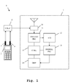
- FIG. 1 an exemplary embodiment of the inventive measuring device 1 is shown.
- a device under test 2 comprises two antennas 3, 4. They are connected to coupling means 5, which are not part of the measuring device 1.
- the coupling means 5 and the measuring device 1 form a measuring system 6.
- the coupling means 5 are connected to input means 10, which are part of the measuring device 1.
- the input means 10 are connected to analog processing means 11, which again are connected to an analog-digital-converter 12.
- the analog-digital-converter 12 is connected to digital processing means 13, which again are connected to display means 14.
- the measuring device 1 comprises control means 15, which are connected to the analog processing means 11, the digital processing means 13 and the display means 14.
- the control means 15 are set up for controlling the function of the connected analog processing means 11, the connected digital processing means 13 and the connected display means 14.
- the device under test 2 sends out at least two signals, each with one of its MIMO antennas 3, 4. These signals are combined into a measuring signal by the coupling means 5.
- the measuring signal is handed on to the input means 10 of the measuring device 1.
- the input means 10 comprise for example a pre-amplifier, which performs a pre-amplification.
- a resulting signal is handed on to the analog processing means 11, which perform analog processing, for example a frequency reduction to the base band and a filtering.
- a resulting signal is handed on to the analog-digital-converter 12, which digitizes the signal and hands it on to the digital processing means 13.
- the digital processing means 13 perform further digital processing, for example a demodulation and a decoding of the individual signals within the measuring signal.
- the digital processing means 13 determine parameters of the measuring signal iteratively. For example, the carrier frequency error, the sample frequency error, the phase noise, the IQ offset and a channel estimation are determined by digital processing means 13. Regarding the function of the digital processing means 13, it is furthermore referred to the elaborations regarding Fig. 2 .
- the results of the digital processing means 13 are handed on to the display means 14 and displayed.
- output means or storage means can be present within the measuring device 1. In this case, the results of the digital processing means 13 are handed to the output means or to the storage means.
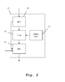
- Fig. 2 shows a detail of the exemplary embodiment of the inventive measuring device.
- the digital processing means 13 comprise transformation means 20, which are connected to the analog-digital-converter 12.
- the transformation means 20 are connected to iteration means 21, which again are connected to parameter setting means 22.
- the iteration means 21 are connected to processing means 23.
- the processing means 23 are connected to the display means 14 of Fig. 1 .
- the iteration means 21, the parameter setting means 22 and the processing means 23 are connected to the control means 15 of Fig. 1 . These connections though are not displayed here.
- the digitized signal is passed on to the transformation means 20 and transformed into the frequency domain.
- the digitized signal is furthermore handed on to the processing means 23.
- the signal in the frequency domain is passed on to the iteration means 21, which iteratively determines the parameters of the measuring signal.
- the parameter setting means 22 set an initial value of at least one of the parameters. Based on this initial value, the further parameters are determined iteratively. As soon as an intermediate value for all of the parameters has been determined, an iterative value for the first parameter, which had been initially set by the parameter setting means 22 is also determined. After a number of iteration has been performed, final values of the parameters are determined and handed on to the processing means 23. Moreover, the signal in the frequency domain is also handed on to the processing means 23.
- the processing means 23 now perform the demodulation and decoding of the signals based upon the parameters determined earlier. Results of the iteration means 21 and of the processing means 23 are handed on to the display means 14 of Fig. 1 .
- Fig. 3 shows an exemplary embodiment of the inventive measuring method.
- a first signal and a second signal which correspond to the antenna signals of the antennas 3, 4 of the device under test of Fig. 1 are added in order to form a measuring signal.
- the measuring signal is received in a second step 101.
- this step also for example a pre-amplification, a frequency reduction, a filtering and a digitizing are performed.
- a first parameter of the measuring signal is set to a pre-defined value.
- an intermediate value of a second parameter is determined based upon the previously set first parameter.
- further intermediate values of parameters are determined based upon the previously set first parameter and the determined intermediate value of the second parameter.
- an intermediate value of the first parameter is determined based upon the previously determined other intermediate values of the parameters. The steps 103 to 105 are repeated until the iterative process converges. Final intermediate parameters are used as the final values of the parameters. Either the number of iterations is preset, or a detection is performed, if the process has already converged. It is important to note, that during the iterative process, each parameter is determined based upon all parameters of the last iteration. In case, there was no last iteration, the parameters are determined based upon the preset first parameter.
- more than one parameter can be preset.
- the intermediate parameters are determined based upon the several preset initial parameters.
- the determined final parameters are output or stored or displayed.
- the delay does not need to be estimated separately and thus is included into the channel transfer function.
- the SFO, CFO and phase noise are assumed to be the same for all transmit antennas. This assumption holds as long as only one reference oscillator is used in the UE and all mixers in the UE use the same local oscillator (LO).
- LO local oscillator
- the channel is different for each subcarrier, while CFO, SFO and phase noise are the same for all subcarriers.
- CFO, SFO, Channel and IQ Offset are assumed to be constant over the duration of a subframe.
- the symbol wise phase noise are assumed to be constant over the duration of one OFDM Symbol.
- Transmit antenna or layer dependency Subcarrier dependency Time dependency CFO none none constant over the duration of a subframe SFO none none constant over the duration of a subframe
- Phase noise none constant over the duration of one OFDM Symbol
- IQ Offset none implicit constant over the duration of a subframe Channel layer dependent Yes constant over the duration of a subframe
- MISO channel estimation For MIMO channel estimation only the MISO channel estimation needs to be derived and considered. For each receive antenna an independent MISO channel estimation can be performed.
- two transmit antennas are connected to one receive antenna.
- the pilot symbols are not transmitted exclusively by one layer or transmit antenna. If the pilots are transmitted exclusively by one layer, the estimation of CFO and SFO can be based on correlating two pilot symbols at different OFDM symbols. In addition the estimation of CFO/SFO can be performed separately from IQ Offset and channel estimation.
- LTE Advanced UL the pilot symbols are transmitted by all layers simultaneously. As the received symbol r l,k consists of the sum of all transmitted pilot symbols, the existing approaches are not possible anymore.
- the estimated intermediate values of the parameters change compared to last iteration. This improvement is an indicator if the iteration already converged and how accurate the estimated values are. The improvement is calculated. If a predefined number of iterations is reached or if the improvement is smaller than a certain threshold, the iteration is stopped.
- the estimation is performed for each subframe independently.
- the DMRS OFDM symbols may be used, so N l is the number of OFDM symbols per subframe.
- N l 2 DMRS OFDM symbols in a subframe.
- the iterative estimation is performed as follows. An iteration consists of the following estimation steps and optionally the last checking step:
- the estimation is performed for each slot independently. This is a requirement of the standard.
- the DMRS and data OFDM symbols with N l being the number of DMRS and data OFDM symbols of a slot are used. This is required to get an estimate of phase noise for each OFDM symbol.
- the IQ Offset and the channel coefficients are initialized with the estimated values from the reference path.
- the iterative estimation is performed as follows. An iteration consists of the following estimation steps and the last checking step:
- the approach uses the PUSCH DMRS symbols of both slots of a subframe and requires that all estimated parameters can be assumed to be constant over this period. Furthermore the approach requires that the same subcarriers / PRBs are active on both slots. As no frequency hopping is allowed for MIMO, this requirement is always fulfilled. The Eq.
- the estimation problem Eq. 15 is a highly over determined system of equations and is solved by Vector Matrix Inversion.
- the number of allocated subcarriers per OFDM symbol is denoted as N k .
- N k The number of allocated subcarriers per OFDM symbol.
- the allocated subcarriers are the same for both slots of a subframe. Additionally, the allocated subcarriers are the same for the DMRS OFDM symbols and data OFDM symbols.
- N l is the number of OFDM symbols per subframe.
- N l 2 DMRS OFDM symbols in a subframe.
- the DMRS and data OFDM symbols with N l being the number of DMRS and data OFDM symbols of a slot are used. This is required to get an estimate of phase noise for each OFDM symbol.
- the estimation problem Eq. 18 can be rewritten in matrix vector notation as follows 2 ⁇ ⁇ ⁇ N s / N FFT ⁇ l 0 ⁇ k 0 2 ⁇ ⁇ ⁇ N s / N FFT ⁇ l 0 ⁇ ⁇ 2 ⁇ ⁇ ⁇ N s / N FFT ⁇ l 0 ⁇ k N k - 1 2 ⁇ ⁇ ⁇ N s / N FFT ⁇ l 0 2 ⁇ ⁇ ⁇ N s / N FFT ⁇ l 1 ⁇ k 0 2 ⁇ ⁇ ⁇ N s / N FFT ⁇ l 1 ⁇ ⁇ 2 ⁇ ⁇ ⁇ N s / N FFT ⁇ l 1 ⁇ k N k - 1 2 ⁇ ⁇ ⁇ N s / N FFT ⁇ l 1 ⁇ ⁇ 2 ⁇ ⁇ ⁇ N s / N FFT ⁇ l 1 ⁇ k N k
- the matrix A and the vector x CFO,SFO are independent from the considered receive antenna p R .
- the vector x CFO,SFO contains the unknowns while A, B and y are known.
- the matrices A and B and its Pseudoinverse can be calculated once before the first iteration and not in every iteration step.
- the estimation problem Eq. 15 can be rewritten in matrix vector notation as follows 2 ⁇ ⁇ ⁇ N s / N FFT ⁇ l 0 ⁇ k 0 2 ⁇ ⁇ ⁇ N s / N FFT ⁇ l 0 1 0 ⁇ 0 ⁇ ⁇ 1 0 ⁇ 0 2 ⁇ ⁇ ⁇ N s / N FFT ⁇ l 0 ⁇ k N k - 1 2 ⁇ ⁇ ⁇ N s / N FFT ⁇ l 0 1 0 ⁇ 0 2 ⁇ ⁇ ⁇ N s / N FFT ⁇ l 1 ⁇ k 0 2 ⁇ ⁇ ⁇ N s / N FFT ⁇ l 1 0 1 ⁇ 0 ⁇ ⁇ N s / N FFT ⁇ l 1 0 1 ⁇ 0 ⁇ ⁇ N s / N FFT ⁇ l 1 0 1 ⁇ 0 ⁇ ⁇ N s /
- the matrices C and D and the scalar ⁇ (SFO) are independent from the considered receive antenna p R .
- the vector x contains the unknowns while E and y are known.
- the matrices E and its Pseudoinverse can be calculated once before the first iteration and not in every iteration step.
- the CPE for all symbols in the subframe can be estimated by a linear interpolation for the symbols between the two DMRS symbols and a linear extrapolation for the symbols at left and right side of the DMRS symbols.
- the channel coefficients H ⁇ k ( p R , ⁇ ) are determined by solving the above system of equations.
- the IQ Offset has only significant influence on the Resource Blocks (RB) around the DC subcarrier.
- the channel estimate is not influenced by the IQ Offset and the IQ Offset does not need to be estimated during Joint Estimation.
- the IQ Offset can be estimated after Joint Estimation on the unallocated RBs around the DC subcarrier.
- an IQ Offset estimation is required.
- the channel and the IQ Offset are estimated separately.
- the IQ Offset is estimated according to Eq. 35.
- the channel estimation of the effective and the physical channel While the effective channel estimate is required to set up a reference signal for the layer and transmit antennas, the physical channel estimate is required to calculate the measurement signal for the transmit antennas and for MISO Time Alignment Measurement. For MISO Time Alignment Measurement, two transmit antennas are connected to one receive antenna.
- MISO channel estimation For each receive antenna and each subcarrier an independent MISO channel estimation can be performed. Thus for MIMO channel estimation only the MISO channel estimation needs to be derived and considered.
- the channel estimation can be performed subframe wise or for each slot independently.
- the final IQ Offset estimate is the mean of the IQ Offset estimates.
- the achieved channel coefficient is valid for the subcarrier in the middle of the group.
- the channel coefficients on the intermediate subcarriers are achieved by interpolation. A linear interpolation may be used.
- the physical channel estimate is calculated using the effective channel estimate and the precoding matrix.
- the following approach uses the PUSCH DMRS symbols only.
- the effective channel(s) from the one and only layer to the receive antenna(s) are estimated. So a reference and a measurement signal for the one and only layer can be generated.
- the precoding matrix is an identity matrix according to the standard. So whether a solution for the physical channel estimation problem exists, depends only on the condition of the matrix B . That is the same as for effective MISO channel estimation.
- the physical channels from the transmit antennas to the receive antenna(s) are required.
- the determinant of the matrix is zero. Due to that the problem Eq. 71 is ill conditioned in case of one layer and the physical MISO channels cannot be estimated. Due to that a MISO Time Alignment Measurement cannot be performed in case of only one layer.
- the precoding matrix is an identity matrix according to the standard. So whether a solution for the physical channel estimation problem exists, depends only on the condition of the matrix C . That is the same as for effective MISO channel estimation.
- H ⁇ k p R ⁇ 0 H ⁇ k p R ⁇ 1 H ⁇ k p R ⁇ 2 H ⁇ k p R ⁇ 3 ⁇ H ⁇ k p R W T ⁇ H k p R ⁇ 0 H k p R ⁇ 1 H k p R ⁇ 2 H k p R ⁇ 3 ⁇ H k p R .
- Fig. 4 results of the iteration are shown.
- the x-axis shows the number of iterations.
- the y-axis shows the error vector magnitude.
- the different curves correspond to measuring signals of different signal-to-noise-ratio. One can clearly see that the process converges even for 60 dB after only a few iterations.
- the invention is not limited to the examples and especially not to the communication standard LTE.
- the invention discussed above can be applied to many different communication standards.
- the characteristics of the exemplary embodiments can be used in any advantageous combination.
Landscapes
- Engineering & Computer Science (AREA)
- Computer Networks & Wireless Communication (AREA)
- Signal Processing (AREA)
- Power Engineering (AREA)
- Radio Transmission System (AREA)
- Indication And Recording Devices For Special Purposes And Tariff Metering Devices (AREA)
- Length Measuring Devices With Unspecified Measuring Means (AREA)
Priority Applications (2)
| Application Number | Priority Date | Filing Date | Title |
|---|---|---|---|
| EP13163952.8A EP2768189A3 (de) | 2013-02-15 | 2013-04-16 | Messvorrichtung und Messverfahren zur gemeinsamen Schätzung von Parametern |
| EP13192655.2A EP2768190B1 (de) | 2013-02-15 | 2013-11-13 | Messvorrichtung und Messverfahren zur gemeinsamen Schätzung von Parametern |
Applications Claiming Priority (2)
| Application Number | Priority Date | Filing Date | Title |
|---|---|---|---|
| EP13155402 | 2013-02-15 | ||
| EP13163952.8A EP2768189A3 (de) | 2013-02-15 | 2013-04-16 | Messvorrichtung und Messverfahren zur gemeinsamen Schätzung von Parametern |
Publications (2)
| Publication Number | Publication Date |
|---|---|
| EP2768189A2 true EP2768189A2 (de) | 2014-08-20 |
| EP2768189A3 EP2768189A3 (de) | 2014-10-08 |
Family
ID=48182707
Family Applications (2)
| Application Number | Title | Priority Date | Filing Date |
|---|---|---|---|
| EP13163952.8A Withdrawn EP2768189A3 (de) | 2013-02-15 | 2013-04-16 | Messvorrichtung und Messverfahren zur gemeinsamen Schätzung von Parametern |
| EP13192655.2A Active EP2768190B1 (de) | 2013-02-15 | 2013-11-13 | Messvorrichtung und Messverfahren zur gemeinsamen Schätzung von Parametern |
Family Applications After (1)
| Application Number | Title | Priority Date | Filing Date |
|---|---|---|---|
| EP13192655.2A Active EP2768190B1 (de) | 2013-02-15 | 2013-11-13 | Messvorrichtung und Messverfahren zur gemeinsamen Schätzung von Parametern |
Country Status (1)
| Country | Link |
|---|---|
| EP (2) | EP2768189A3 (de) |
Families Citing this family (5)
| Publication number | Priority date | Publication date | Assignee | Title |
|---|---|---|---|---|
| CN108259401B (zh) | 2016-12-28 | 2020-09-15 | 电信科学技术研究院 | 参考信号发送方法和相位噪声确定方法及相关装置 |
| CN109150777B (zh) * | 2017-06-16 | 2023-11-10 | 华为技术有限公司 | 参考信号的传输方法和传输装置 |
| CN109391571B (zh) * | 2017-08-11 | 2020-12-04 | 华为技术有限公司 | 相位噪声估计方法及设备 |
| CN112235215B (zh) * | 2020-09-09 | 2022-09-13 | 鹏城实验室 | 一种无线信道探测方法、存储介质及终端设备 |
| CN114584447B (zh) * | 2022-01-12 | 2023-10-20 | 华信咨询设计研究院有限公司 | 一种基于偏移噪声的5g cfo估计方法 |
Citations (2)
| Publication number | Priority date | Publication date | Assignee | Title |
|---|---|---|---|---|
| WO2008116534A1 (de) | 2007-03-26 | 2008-10-02 | Rohde & Schwarz Gmbh & Co. Kg | Verfahren und vorrichtung zur ermittlung einer unverkürzten kanalimpulsantwort in einem ofdm-übertragungssystem |
| DE102011077390A1 (de) | 2011-06-10 | 2012-12-13 | Rohde & Schwarz Gmbh & Co. Kg | Messgerät und Verfahren zur Vermessung eines Signals mit mehreren Teilsignalen |
-
2013
- 2013-04-16 EP EP13163952.8A patent/EP2768189A3/de not_active Withdrawn
- 2013-11-13 EP EP13192655.2A patent/EP2768190B1/de active Active
Patent Citations (2)
| Publication number | Priority date | Publication date | Assignee | Title |
|---|---|---|---|---|
| WO2008116534A1 (de) | 2007-03-26 | 2008-10-02 | Rohde & Schwarz Gmbh & Co. Kg | Verfahren und vorrichtung zur ermittlung einer unverkürzten kanalimpulsantwort in einem ofdm-übertragungssystem |
| DE102011077390A1 (de) | 2011-06-10 | 2012-12-13 | Rohde & Schwarz Gmbh & Co. Kg | Messgerät und Verfahren zur Vermessung eines Signals mit mehreren Teilsignalen |
Also Published As
| Publication number | Publication date |
|---|---|
| EP2768190B1 (de) | 2019-01-09 |
| EP2768190A3 (de) | 2014-10-08 |
| EP2768189A3 (de) | 2014-10-08 |
| EP2768190A2 (de) | 2014-08-20 |
Similar Documents
| Publication | Publication Date | Title |
|---|---|---|
| EP2768189A2 (de) | Messvorrichtung und Messverfahren zur gemeinsamen Schätzung von Parametern | |
| JP6858237B2 (ja) | スパース順序付け反復群マルチアンテナチャネル推定 | |
| EP2777337B1 (de) | Mehrstufige zeit und frequenzsynchronization. | |
| US20100128807A1 (en) | Method for estimating channel in radio communication system and device therefor | |
| EP3104570B1 (de) | Minimierung der interferenz zwischen symbolen in ofdm-signalen | |
| WO2015165354A1 (zh) | 一种功率时延谱pdp估计方法及装置 | |
| TWI488467B (zh) | 用於全球互通微波存取之上行鏈路分域多重存取接收器 | |
| EP2846504B1 (de) | Messvorrichtung und Messverfahren zur gemeinsamen Schätzung von Parametern auf Grundlage von Datensymbolen | |
| JP2009081535A (ja) | 通信装置及び希望波伝送路特性算出方法 | |
| CN106027429A (zh) | 处理多个信号的方法和信号处理设备 | |
| CN105072063B (zh) | 一种抑制干扰信号的方法和装置 | |
| EP2144414A1 (de) | Verfahren zur Kompensation von Informationsverlusten bei einem Mehrträgerkommunikationssignal auf OFDM-Basis, die durch die Ausblendung von impulsförmigen Interferenzen verursacht wurden | |
| US10256996B2 (en) | Reduced dimension channel estimation in a wireless communication network | |
| Goubet et al. | Low-complexity scalable iterative algorithms for IEEE 802.11 p receivers | |
| EP2924936A1 (de) | Kanalschätzungsverfahren und vorrichtung | |
| US20220321384A1 (en) | Method of channel estimation in a communication system as well as signal processing system | |
| US20140219370A1 (en) | Signal processing in a cooperative ofdm communication system | |
| EP2775682B1 (de) | Messungsvorrichtung und Verfahren für Rahmenstartdetektion | |
| Suárez-Casal et al. | Experimental assessment of WiMAX transmissions under highly time-varying channels | |
| US9929882B1 (en) | Method and apparatus for accurately estimating a distance between wireless network devices | |
| EP2595352B1 (de) | Verfahren und Vorrichtung zur verbesserten Kanalschätzung unter Verwendung einer frame-basierten Kompensation der Kanaländerungen | |
| Zieliński et al. | Wireless OTFS-based Integrated Sensing and Communication for Moving Vehicle Detection | |
| EP3425834A1 (de) | Verfahren zur unterdrückung von interferenz und rauschsignal zwischen unterträgern und orthogonal-frequency-division-multiplexing-empfänger zur ausführung davon | |
| US8891705B1 (en) | Methods for signal processing to reduce inter-symbol-interference | |
| US20150029831A1 (en) | LTE-Advanced Transmit Diversity Decoders |
Legal Events
| Date | Code | Title | Description |
|---|---|---|---|
| PUAI | Public reference made under article 153(3) epc to a published international application that has entered the european phase |
Free format text: ORIGINAL CODE: 0009012 |
|
| 17P | Request for examination filed |
Effective date: 20130416 |
|
| AK | Designated contracting states |
Kind code of ref document: A2 Designated state(s): AL AT BE BG CH CY CZ DE DK EE ES FI FR GB GR HR HU IE IS IT LI LT LU LV MC MK MT NL NO PL PT RO RS SE SI SK SM TR |
|
| AX | Request for extension of the european patent |
Extension state: BA ME |
|
| PUAL | Search report despatched |
Free format text: ORIGINAL CODE: 0009013 |
|
| AK | Designated contracting states |
Kind code of ref document: A3 Designated state(s): AL AT BE BG CH CY CZ DE DK EE ES FI FR GB GR HR HU IE IS IT LI LT LU LV MC MK MT NL NO PL PT RO RS SE SI SK SM TR |
|
| AX | Request for extension of the european patent |
Extension state: BA ME |
|
| RIC1 | Information provided on ipc code assigned before grant |
Ipc: H04L 27/26 20060101ALI20140829BHEP Ipc: H04L 25/02 20060101AFI20140829BHEP Ipc: H04B 7/04 20060101ALI20140829BHEP |
|
| STAA | Information on the status of an ep patent application or granted ep patent |
Free format text: STATUS: THE APPLICATION IS DEEMED TO BE WITHDRAWN |
|
| 18D | Application deemed to be withdrawn |
Effective date: 20150409 |