EP2767885A2 - Hand-held electronic device - Google Patents
Hand-held electronic device Download PDFInfo
- Publication number
- EP2767885A2 EP2767885A2 EP14155352.9A EP14155352A EP2767885A2 EP 2767885 A2 EP2767885 A2 EP 2767885A2 EP 14155352 A EP14155352 A EP 14155352A EP 2767885 A2 EP2767885 A2 EP 2767885A2
- Authority
- EP
- European Patent Office
- Prior art keywords
- casing
- face
- cover
- hand
- electronic device
- Prior art date
- Legal status (The legal status is an assumption and is not a legal conclusion. Google has not performed a legal analysis and makes no representation as to the accuracy of the status listed.)
- Granted
Links
- 238000001816 cooling Methods 0.000 claims abstract description 33
- 239000003570 air Substances 0.000 description 23
- 230000000694 effects Effects 0.000 description 9
- 230000002093 peripheral effect Effects 0.000 description 6
- 238000004519 manufacturing process Methods 0.000 description 4
- 230000002411 adverse Effects 0.000 description 2
- 239000012080 ambient air Substances 0.000 description 1
- 239000011521 glass Substances 0.000 description 1
- 239000000463 material Substances 0.000 description 1
Images


Classifications
-
- G—PHYSICS
- G06—COMPUTING; CALCULATING OR COUNTING
- G06F—ELECTRIC DIGITAL DATA PROCESSING
- G06F1/00—Details not covered by groups G06F3/00 - G06F13/00 and G06F21/00
- G06F1/16—Constructional details or arrangements
- G06F1/20—Cooling means
- G06F1/203—Cooling means for portable computers, e.g. for laptops
-
- H—ELECTRICITY
- H05—ELECTRIC TECHNIQUES NOT OTHERWISE PROVIDED FOR
- H05K—PRINTED CIRCUITS; CASINGS OR CONSTRUCTIONAL DETAILS OF ELECTRIC APPARATUS; MANUFACTURE OF ASSEMBLAGES OF ELECTRICAL COMPONENTS
- H05K7/00—Constructional details common to different types of electric apparatus
- H05K7/20—Modifications to facilitate cooling, ventilating, or heating
- H05K7/20009—Modifications to facilitate cooling, ventilating, or heating using a gaseous coolant in electronic enclosures
- H05K7/20136—Forced ventilation, e.g. by fans
- H05K7/20145—Means for directing air flow, e.g. ducts, deflectors, plenum or guides
Definitions
- the present invention relates to a hand-held electronic device and, more particularly, to a hand-held electronic device capable of reducing the temperature of its electronic component.
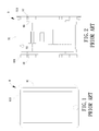
- FIG. 1 shows a conventional hand-held electronic device 8 including an enclosure 81 defining a compartment in which a processor and a fan are received.
- the enclosure 81 includes a peripheral wall having a receiving port 811.
- the fan can be operated to make air flow through the receiving port 811 for exchanging the air in the compartment with the ambient air surrounding the enclosure 81, thereby cooling the processor.
- An example of such a hand-held electronic device 8 is disclosed in U.S. Patent No. 8,477,490 B2 .
- FIG. 2 shows a conventional cell phone 9 including a casing 91 receiving electronic elements.
- the casing 91 includes two parallel lateral sides 911 each having a plurality of vents 92.
- a fan 93 is mounted in a location adjacent to each vent 92 and can be operated to cool the electronic elements.
- An example of such a cell phone 9 is disclosed in Taiwan Patent Publication No. 201238317 .
- the receiving port 811 of the hand-held electronic device 8 and the vents 92 of the cell phone 9 are arranged on the peripheral walls of the enclosure 81 and the casing 91, respectively.
- the user in use, the user must hold the enclosure 81 or casing 91 with a hand such that the hand of the user may directly cover the receiving port 811 or vents 92, adversely affecting the air intake or outtake function of the receiving port 811 or vents 92.
- the cooling effect is reduced.
- An objective of the present invention is to provide a hand-held electronic device preventing the hand of the user from covering the vents, avoiding adverse affect to the air intake or outtake and achieving the expected cooling effect.
- the present invention fulfills the above objective by providing a hand-held electronic device including a casing having a first face and a second face opposite to the first face.
- the casing includes an interior intermediate the first face and the second face of the casing.
- a first cover includes a thickness forming an annular periphery and abuts the first face of the casing.
- a joining area between the annular periphery of the first cover and the first face of the casing includes a junction section having at least one vent in communication with the interior of the casing.
- An electronic component is mounted in the interior of the casing.
- a cooling fan is mounted in the interior of the casing. The cooling fan is adapted to guide air currents via the at least one vent to cool the electronic component.
- the at least one vent is defined in the first face of the casing and adjoins the junction section.
- the at least one vent is defined in the annular periphery of the first cover and adjoins the junction section.
- the at least one vent includes a first opening defined in the first face of the casing and a second opening defined in the first cover, with the first and second openings together forming the at least one vent.
- the at least one vent includes a plurality of vents distributed along two sides of the first cover.
- the two sides of the first cover are opposite to or adjacent to each other.
- the at least one vent is a continuous elongated slot.
- the at least one vent is provided at at least one corner of the first cover.
- the annular periphery of the first cover intersects the first face of the casing by only one side, and the side of the annular periphery of the first cover includes the junction section.
- a display is mounted to the first face of the casing, and the first cover abuts the first face of the casing and covers the display.
- a second cover abuts the second face of the casing.
- the second cover covers a portion of the second face of the casing.
- a junction section between the second face of the casing and the second cover includes at least one auxiliary vent.
- the at least one auxiliary vent is defined in the second face of the casing and adjoins the junction section between the second face of the casing and the second cover.
- the at least one auxiliary vent includes a plurality of auxiliary vents distributed along two sides of the second cover. The two sides of the second cover are opposite to or adjacent to each other.
- the at least one auxiliary vent is a continuous elongated slot.
- a hand-held electronic device can be a cell phone, a tablet computer, a hand-held game console, a music player, a digital video cassette camcorder, or a digital camera.
- the hand-held electronic device will be described by way of example of a cell phone without any limiting purposes.
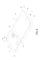
- FIGS. 3 and 4 show a hand-held electronic device of a first embodiment according to the present invention.
- the hand-held electronic device includes a casing 1, a first cover 2, an electronic component 3, and a cooling fan 4.
- the first cover 2 is mounted to an outer side of the casing 1.
- the electronic component 3 and the cooling fan 4 are mounted in an interior of the casing 1. When the cooling fan 4 operates, air currents are guided into and out of the casing 1 to reduce the operating temperature of the electronic component 3.
- the casing 1 includes a first face 11 and a second face 12 opposite to the first face 11.
- the interior of the casing 1 is intermediate the first face 11 and the second face 12.
- a peripheral wall 13 is provided between the first face 11 and the second face 12.
- the first face 11 of the casing 1 faces a user when the hand-held electronic device is in use.
- the casing 1 further includes a frame 14 and a display 15.
- the frame 14 surrounds an outer periphery of the display 15 and is located adjacent to the first face 11 of the casing 1.
- the first cover 2 can be made of a material such as reinforced glass.
- the first cover 2 abuts the first face 11 of the casing 1 and covers the display 15 and a portion of the frame 14 to protect the display 15 from impact and wear.
- the first cover 2 includes a thickness forming an annular periphery 21.
- a joining area between the annular periphery 21 of the first cover 2 and the first face 11 of the casing 1 includes a junction section C1 having at least one vent 5a in communication with the interior and an exterior of the casing 1.
- the at least one vent 5a is formed in the first face 11 of the casing 1 and is located adjacent to the junction section C1 to allow easy manufacture.
- the at least one vent 5a includes a plurality of vents 5a distributed along two sides of the first cover 2, with the two sides of the first cover 2 opposite to or adjacent to each other.
- the vents 5a can be located on left and right sides or upper and lower sides of the first cover 2.
- the vents 5a can be located on the upper and right sides or the upper, left and right sides of the first cover 2 to provide a better air guiding effect. Even if some of the vents 5a are covered, the cooling fan 4 can guide air currents into the casing 1 via the vents 5a that are not covered.
- At least one of the vents 5a can be in the form of a continuous elongated slot.
- the intercommunicating area between the interior and the exterior of the casing 1 can be increased to further increase the heat dissipating effect while allowing easy manufacture.
- plural vents 5a are provided on two opposite sides or two adjacent sides of the first cover 2.
- the at least one vent 5a is provided at at least one corner of the first cover 2.
- a vent 5a is provided at each corner of the first cover 2.
- the vents 5a are located in positions less likely to be blocked by the hand of the user to maintain excellent cooling efficiency of the hand-held electronic device.
- the annular periphery 21 of the first cover 2 intersects the first face 11 of the casing 1 by only one side, and this side of the annular periphery 21 of the first cover 2 includes the junction section C1. Furthermore, all of the vents 5a are located on the junction section C1.
- the area of the frame 14 covered by the first cover 2 is not limited to the illustrated examples.
- the electronic component 3 and the cooling fan 4 are both mounted in the interior of the casing 1.
- the electronic component 3 can be a processor of a cell phone.
- the cooling fan 4 is adapted to guide air currents via the at least one vent 5a to cool the electronic component 3.
- the cooling fan 4 is located adjacent to the electronic component 3 to increase the cooling efficiency of the electronic component 3.
- the cooling fan 4 is a centrifugal fan and preferably a double inlet type centrifugal fan.
- the cooling fan 4 includes an air inlet 41 in an axial direction and an air outlet 42 in a radial direction.
- the air outlet 42 is located adjacent to the vents 5a on a side of the first cover 2.
- the low-temperature air outside the casing 1 can flow into the casing 1 and pass through the electronic component 3 to carry away the heat generated during operation of the electronic component 3.
- the high-temperature air in the interior of the casing 1 can be expelled by the cooling fan 4 to lower the operational temperature of the electronic component 3, maintaining normal operation.
- the at least one vent 5a can be located in the junction section C1 between the first face 11 of the casing 1 and the first cover 2 and is, thus, located in a stepped portion less likely to be blocked by the hand of the user.
- the at least one vent 5a can maintain communication between the interior and exterior of the casing 1, allowing the cooling fan 4 to smoothly guide air currents into and out of the casing 1 and providing the electronic component 3 with a continuous cooling effect.
- vents 5a are defined in the first face 11 of the casing 1 facing the user such that the vents 5a always face the user without obstruction by the hand of the user using the hand-held electronic device, further increasing the cooling effect of the electronic component 3 by the cooling fan 4.
- a second cover 6 is provided and abuts the second face 12 of the casing 1 to increase the structural strength of the hand-held electronic device for protecting the electronic component 3 in the casing 1.
- the first face 11 and the second face 12 of the casing 1 can be a plane.
- the peripheral wall 13 is connected to peripheral edges of the first face 11 and the second face 12 to form the casing 1 in the form of a box-like parallelepiped.
- the second cover 6 can only cover a portion of the second face 12 of the casing 1 to form a symmetric arrangement to the first cover 2 abutting the first face 11 of the casing 1, forming a stepped portion between the second cover 6 and the second face 12 of the casing 1.
- a junction section C2 between the second face 12 of the casing 1 and the second cover 6 can include at least one auxiliary vent 5a'.
- the at least one auxiliary vent 5a' is defined in the second face 12 of the casing 1 and adjoins the junction section C2 between the second face 12 of the casing 1 and the second cover 6.
- plural auxiliary vents 5a' are provided and distributed along two sides of the second cover 6, with the two sides of the second cover 6 opposite to or adjacent to each other, providing enhanced air guiding effect.
- the at least one auxiliary vent 5a' can be a continuous elongated slot to increase the cooling efficiency while allowing easy manufacture.
- the first face 11 of the casing 1 faces away from the user using the hand-held electronic device, and the second face 12 of the casing 1 faces the user.
- the frame 14 and the display 15 are located adjacent to the second face 12 of the casing 1.
- the first cover 2 abuts the first face 11, and a junction section C1 is provided at the joining area between the first cover 2 and the first face 11.
- the second cover 6 abuts the second face 12, and another junction section C2 is provided between the joining area between the second cover 6 and the second face 12.
- the junction section C2 between the second face 12 of the casing 1 and the second cover 6 can be closed and free of holes. Furthermore, the vents 5a are provided on the first face 11 of the casing 1 and adjoin the junction section C1 between the first face 11 and the first cover 2.
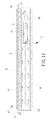
- FIGS. 10 and 11 illustrate a second embodiment of the present invention substantially the same as the first embodiment except that the at least one vent 5b is defined in the annular periphery 21 of the first cover 2 and adjoins the junction section C1.
- the at least one vent 5b is located in a position farther to the peripheral wall 13 of the casing 1, further avoiding the at least one vent 5b from being covered.
- the at least one vent 5b in the annular periphery 21 of the first cover 2 makes the opening of the at least one vent 5b face two lateral sides of the hand-held electronic device.
- the hot air is guided by the cooling fan 4 and is discharged via the lateral sides of the hand-held electronic device, rather than discharged toward the user.
- FIGS. 12 and 13 illustrate a third embodiment of the present invention substantially the same as the second embodiment except that the at least one vent 5c includes a first opening 51 defined in the first face 11 of the casing 1 and a second opening 52 defined in the first cover 2, with the first and second openings 51, 52 together forming the at least one vent 5c.
- the at least one vent 5c of the third embodiment reduce the holed areas in the casing 1 and the first cover 2, increasing the structural strengths of the casing 1 and the first cover 2.
- the first opening 51 and the second opening 52 can be completely or partially aligned with each other.
- the at least one vent 5a, 5a', 5b, 5c in the junction section C1, C2 between the first cover 2 and/or the second cover 6 and the first face 11 and/or the second face 12 of the casing 1, the at least one vent 5a, 5a', 5b, 5c is located in a stepped portion of the hand-held electronic device according to the present invention and is, thus, less likely to be blocked by the hand of the user.
- the at least one vent 5a, 5a', 5b, 5c can intercommunicate the interior of the casing 1 with the outside, allowing the cooling fan 4 to smoothly guide air currents into and out of the casing 1, achieving the expected cooling effect.
Landscapes
- Engineering & Computer Science (AREA)
- Theoretical Computer Science (AREA)
- Physics & Mathematics (AREA)
- Microelectronics & Electronic Packaging (AREA)
- Computer Hardware Design (AREA)
- Human Computer Interaction (AREA)
- General Engineering & Computer Science (AREA)
- General Physics & Mathematics (AREA)
- Thermal Sciences (AREA)
- Cooling Or The Like Of Electrical Apparatus (AREA)
- Casings For Electric Apparatus (AREA)
- Telephone Set Structure (AREA)
Abstract
Description
- The present invention relates to a hand-held electronic device and, more particularly, to a hand-held electronic device capable of reducing the temperature of its electronic component.
-
FIG. 1 shows a conventional hand-heldelectronic device 8 including anenclosure 81 defining a compartment in which a processor and a fan are received. Theenclosure 81 includes a peripheral wall having areceiving port 811. The fan can be operated to make air flow through thereceiving port 811 for exchanging the air in the compartment with the ambient air surrounding theenclosure 81, thereby cooling the processor. An example of such a hand-heldelectronic device 8 is disclosed inU.S. Patent No. 8,477,490 B2 . -
FIG. 2 shows aconventional cell phone 9 including acasing 91 receiving electronic elements. Thecasing 91 includes two parallellateral sides 911 each having a plurality ofvents 92. Afan 93 is mounted in a location adjacent to eachvent 92 and can be operated to cool the electronic elements. An example of such acell phone 9 is disclosed in Taiwan Patent Publication No.201238317 - The
receiving port 811 of the hand-heldelectronic device 8 and thevents 92 of thecell phone 9 are arranged on the peripheral walls of theenclosure 81 and thecasing 91, respectively. However, in use, the user must hold theenclosure 81 orcasing 91 with a hand such that the hand of the user may directly cover thereceiving port 811 orvents 92, adversely affecting the air intake or outtake function of thereceiving port 811 orvents 92. Thus, the cooling effect is reduced. - Thus, a need exists for a novel hand-held electronic device with improved cooling effect.
- An objective of the present invention is to provide a hand-held electronic device preventing the hand of the user from covering the vents, avoiding adverse affect to the air intake or outtake and achieving the expected cooling effect.
- The present invention fulfills the above objective by providing a hand-held electronic device including a casing having a first face and a second face opposite to the first face. The casing includes an interior intermediate the first face and the second face of the casing. A first cover includes a thickness forming an annular periphery and abuts the first face of the casing. A joining area between the annular periphery of the first cover and the first face of the casing includes a junction section having at least one vent in communication with the interior of the casing. An electronic component is mounted in the interior of the casing. A cooling fan is mounted in the interior of the casing. The cooling fan is adapted to guide air currents via the at least one vent to cool the electronic component.
- In an example, the at least one vent is defined in the first face of the casing and adjoins the junction section.
- In another example, the at least one vent is defined in the annular periphery of the first cover and adjoins the junction section.
- In a further example, the at least one vent includes a first opening defined in the first face of the casing and a second opening defined in the first cover, with the first and second openings together forming the at least one vent.
- In still another example, the at least one vent includes a plurality of vents distributed along two sides of the first cover. The two sides of the first cover are opposite to or adjacent to each other.
- In yet another example, the at least one vent is a continuous elongated slot.
- In still another example, the at least one vent is provided at at least one corner of the first cover.
- In yet another example, the annular periphery of the first cover intersects the first face of the casing by only one side, and the side of the annular periphery of the first cover includes the junction section.
- Preferably, a display is mounted to the first face of the casing, and the first cover abuts the first face of the casing and covers the display.
- In still another example, a second cover abuts the second face of the casing. The second cover covers a portion of the second face of the casing. A junction section between the second face of the casing and the second cover includes at least one auxiliary vent. The at least one auxiliary vent is defined in the second face of the casing and adjoins the junction section between the second face of the casing and the second cover. In an example, the at least one auxiliary vent includes a plurality of auxiliary vents distributed along two sides of the second cover. The two sides of the second cover are opposite to or adjacent to each other. In an alternative example, the at least one auxiliary vent is a continuous elongated slot.
- The present invention will become clearer in light of the following detailed description of illustrative embodiments of this invention described in connection with the drawings.
- The illustrative embodiments may best be described by reference to the accompanying drawings where:
-
FIG. 1 is a perspective view of a conventional hand-held electronic device. -
FIG. 2 is a schematic view of a conventional cell phone. -
FIG. 3 is a perspective view of a hand-held electronic device of a first embodiment according to the present invention. -
FIG. 4 is a cross sectional view taken along section line 4-4 ofFIG. 3 . -
FIG. 5 is a perspective view of another example of the hand-held electronic device of the first embodiment according to the present invention, with the hand-held electronic device including two elongated vents. -
FIG. 6 is a perspective view of a further example of the hand-held electronic device of the first embodiment according to the present invention, with a vent provided at each of four corners of a first cover of the hand-held electronic device. -
FIG. 7 is a perspective view of still another example of the hand-held electronic device of the first embodiment according to the present invention, with vents formed along a side of the first cover. -
FIG. 8 is a cross sectional view of yet another example of the hand-held electronic device of the first embodiment according to the present invention, with the hand-held electronic device including a second cover and auxiliary vents. -
FIG. 9 is a cross sectional view of still another example of the hand-held electronic device of the first embodiment according to the present invention, with the vents formed in the second cover only. -
FIG. 10 is a perspective view of a hand-held electronic device of a second embodiment according to the present invention. -
FIG. 11 is a cross sectional view taken along section line 11-11 ofFIG. 10 . -
FIG. 12 is a perspective view of a hand-held electronic device of a third embodiment according to the present invention. -
FIG. 13 is a cross sectional view taken along section line 13-13 ofFIG. 12 . - A hand-held electronic device according to the present invention can be a cell phone, a tablet computer, a hand-held game console, a music player, a digital video cassette camcorder, or a digital camera. The hand-held electronic device will be described by way of example of a cell phone without any limiting purposes.
-
FIGS. 3 and4 show a hand-held electronic device of a first embodiment according to the present invention. Specifically, the hand-held electronic device includes acasing 1, afirst cover 2, anelectronic component 3, and acooling fan 4. Thefirst cover 2 is mounted to an outer side of thecasing 1. Theelectronic component 3 and the coolingfan 4 are mounted in an interior of thecasing 1. When the coolingfan 4 operates, air currents are guided into and out of thecasing 1 to reduce the operating temperature of theelectronic component 3. - The
casing 1 includes afirst face 11 and asecond face 12 opposite to thefirst face 11. The interior of thecasing 1 is intermediate thefirst face 11 and thesecond face 12. Aperipheral wall 13 is provided between thefirst face 11 and thesecond face 12. In the embodiment shown inFIG. 3 , thefirst face 11 of thecasing 1 faces a user when the hand-held electronic device is in use. Thecasing 1 further includes aframe 14 and adisplay 15. Theframe 14 surrounds an outer periphery of thedisplay 15 and is located adjacent to thefirst face 11 of thecasing 1. - The
first cover 2 can be made of a material such as reinforced glass. Thefirst cover 2 abuts thefirst face 11 of thecasing 1 and covers thedisplay 15 and a portion of theframe 14 to protect thedisplay 15 from impact and wear. Thefirst cover 2 includes a thickness forming anannular periphery 21. A joining area between theannular periphery 21 of thefirst cover 2 and thefirst face 11 of thecasing 1 includes a junction section C1 having at least onevent 5a in communication with the interior and an exterior of thecasing 1. In this embodiment, the at least onevent 5a is formed in thefirst face 11 of thecasing 1 and is located adjacent to the junction section C1 to allow easy manufacture. Preferably, the at least onevent 5a includes a plurality ofvents 5a distributed along two sides of thefirst cover 2, with the two sides of thefirst cover 2 opposite to or adjacent to each other. For example, thevents 5a can be located on left and right sides or upper and lower sides of thefirst cover 2. Alternatively, thevents 5a can be located on the upper and right sides or the upper, left and right sides of thefirst cover 2 to provide a better air guiding effect. Even if some of thevents 5a are covered, the coolingfan 4 can guide air currents into thecasing 1 via thevents 5a that are not covered. - Alternatively, as shown in
FIG. 5 , at least one of thevents 5a can be in the form of a continuous elongated slot. Thus, the intercommunicating area between the interior and the exterior of thecasing 1 can be increased to further increase the heat dissipating effect while allowing easy manufacture. Preferably,plural vents 5a are provided on two opposite sides or two adjacent sides of thefirst cover 2. In another example, the at least onevent 5a is provided at at least one corner of thefirst cover 2. In the example shown inFIG. 6 , avent 5a is provided at each corner of thefirst cover 2. Thus, thevents 5a are located in positions less likely to be blocked by the hand of the user to maintain excellent cooling efficiency of the hand-held electronic device. - In a further example shown in
FIG. 7 , theannular periphery 21 of thefirst cover 2 intersects thefirst face 11 of thecasing 1 by only one side, and this side of theannular periphery 21 of thefirst cover 2 includes the junction section C1. Furthermore, all of thevents 5a are located on the junction section C1. Thus, the area of theframe 14 covered by thefirst cover 2 is not limited to the illustrated examples. - The
electronic component 3 and the coolingfan 4 are both mounted in the interior of thecasing 1. Theelectronic component 3 can be a processor of a cell phone. The coolingfan 4 is adapted to guide air currents via the at least onevent 5a to cool theelectronic component 3. Preferably, the coolingfan 4 is located adjacent to theelectronic component 3 to increase the cooling efficiency of theelectronic component 3. - In this embodiment, the cooling
fan 4 is a centrifugal fan and preferably a double inlet type centrifugal fan. The coolingfan 4 includes anair inlet 41 in an axial direction and anair outlet 42 in a radial direction. Theair outlet 42 is located adjacent to thevents 5a on a side of thefirst cover 2. When the coolingfan 4 operates, the air in the interior of thecasing 1 is guided by the coolingfan 4 to pass through thevents 5a adjacent to theair outlet 42 to the outside, forming a negative pressure in the interior of thecasing 1. Thus, air outside thecasing 1 is guided into the interior of thecasing 1 via thevents 5a on the other side of thefirst cover 2. Accordingly, the low-temperature air outside thecasing 1 can flow into thecasing 1 and pass through theelectronic component 3 to carry away the heat generated during operation of theelectronic component 3. As a result, the high-temperature air in the interior of thecasing 1 can be expelled by the coolingfan 4 to lower the operational temperature of theelectronic component 3, maintaining normal operation. - By the above structural features, the at least one
vent 5a can be located in the junction section C1 between thefirst face 11 of thecasing 1 and thefirst cover 2 and is, thus, located in a stepped portion less likely to be blocked by the hand of the user. Thus, when the user is using the hand-held electronic device, the at least onevent 5a can maintain communication between the interior and exterior of thecasing 1, allowing the coolingfan 4 to smoothly guide air currents into and out of thecasing 1 and providing theelectronic component 3 with a continuous cooling effect. Furthermore, in the embodiment shown inFIG. 3 , thevents 5a are defined in thefirst face 11 of thecasing 1 facing the user such that thevents 5a always face the user without obstruction by the hand of the user using the hand-held electronic device, further increasing the cooling effect of theelectronic component 3 by the coolingfan 4. - Based on the above technical concept of the hand-held electronic device according to the present invention, other structural features can be included to provide more functions.
- With reference to
FIG. 8 , asecond cover 6 is provided and abuts thesecond face 12 of thecasing 1 to increase the structural strength of the hand-held electronic device for protecting theelectronic component 3 in thecasing 1. Furthermore, thefirst face 11 and thesecond face 12 of thecasing 1 can be a plane. Theperipheral wall 13 is connected to peripheral edges of thefirst face 11 and thesecond face 12 to form thecasing 1 in the form of a box-like parallelepiped. Thesecond cover 6 can only cover a portion of thesecond face 12 of thecasing 1 to form a symmetric arrangement to thefirst cover 2 abutting thefirst face 11 of thecasing 1, forming a stepped portion between thesecond cover 6 and thesecond face 12 of thecasing 1. Thus, a junction section C2 between thesecond face 12 of thecasing 1 and thesecond cover 6 can include at least oneauxiliary vent 5a'. To allow easy manufacture, the at least oneauxiliary vent 5a' is defined in thesecond face 12 of thecasing 1 and adjoins the junction section C2 between thesecond face 12 of thecasing 1 and thesecond cover 6. Preferably, pluralauxiliary vents 5a' are provided and distributed along two sides of thesecond cover 6, with the two sides of thesecond cover 6 opposite to or adjacent to each other, providing enhanced air guiding effect. Alternatively, the at least oneauxiliary vent 5a' can be a continuous elongated slot to increase the cooling efficiency while allowing easy manufacture. - With reference to
FIG. 9 , in still another example of the first embodiment according to the present invention, thefirst face 11 of thecasing 1 faces away from the user using the hand-held electronic device, and thesecond face 12 of thecasing 1 faces the user. Namely, theframe 14 and thedisplay 15 are located adjacent to thesecond face 12 of thecasing 1. Furthermore, thefirst cover 2 abuts thefirst face 11, and a junction section C1 is provided at the joining area between thefirst cover 2 and thefirst face 11. Thesecond cover 6 abuts thesecond face 12, and another junction section C2 is provided between the joining area between thesecond cover 6 and thesecond face 12. - In the example shown in
FIG. 9 , the junction section C2 between thesecond face 12 of thecasing 1 and thesecond cover 6 can be closed and free of holes. Furthermore, thevents 5a are provided on thefirst face 11 of thecasing 1 and adjoin the junction section C1 between thefirst face 11 and thefirst cover 2. By such an arrangement, when the hand-held electronic device is in use, the coolingfan 4 guides the high-temperature air to exit the rear side of the hand-held electronic device instead of sending the high-temperature air to the user, increasing the use comfort of the hand-held electronic device. -
FIGS. 10 and11 illustrate a second embodiment of the present invention substantially the same as the first embodiment except that the at least onevent 5b is defined in theannular periphery 21 of thefirst cover 2 and adjoins the junction section C1. Thus, the at least onevent 5b is located in a position farther to theperipheral wall 13 of thecasing 1, further avoiding the at least onevent 5b from being covered. Furthermore, the at least onevent 5b in theannular periphery 21 of thefirst cover 2 makes the opening of the at least onevent 5b face two lateral sides of the hand-held electronic device. Thus, the hot air is guided by the coolingfan 4 and is discharged via the lateral sides of the hand-held electronic device, rather than discharged toward the user. -
FIGS. 12 and13 illustrate a third embodiment of the present invention substantially the same as the second embodiment except that the at least onevent 5c includes afirst opening 51 defined in thefirst face 11 of thecasing 1 and asecond opening 52 defined in thefirst cover 2, with the first andsecond openings vent 5c. Compared to the first and second embodiments, the at least onevent 5c of the third embodiment reduce the holed areas in thecasing 1 and thefirst cover 2, increasing the structural strengths of thecasing 1 and thefirst cover 2. Thefirst opening 51 and thesecond opening 52 can be completely or partially aligned with each other. - In view of the foregoing, by providing the at least one
vent first cover 2 and/or thesecond cover 6 and thefirst face 11 and/or thesecond face 12 of thecasing 1, the at least onevent vent casing 1 with the outside, allowing the coolingfan 4 to smoothly guide air currents into and out of thecasing 1, achieving the expected cooling effect. - Thus since the invention disclosed herein may be embodied in other specific forms without departing from the spirit or general characteristics thereof, some of which forms have been indicated, the embodiments described herein are to be considered in all respects illustrative and not restrictive. The scope of the invention is to be indicated by the appended claims, rather than by the foregoing description, and all changes which come within the meaning and range of equivalency of the claims are intended to be embraced therein.
Claims (14)
- A hand-held electronic device comprising:a casing (1) including a first face (11) and a second face (12) opposite to the first face (11), with the casing (1) including an interior intermediate the first face (11) and the second face (12) of the casing (1);an electronic component (3) mounted in the interior of the casing (1); anda cooling fan (4) mounted in the interior of the casing (1),wherein the hand-held electronic device is characterized in further comprising a first cover (2) including a thickness forming an annular periphery (21), with the first cover (2) abutting the first face (11) of the casing (1), with a joining area between the annular periphery (21) of the first cover (2) and the first face (11) of the casing (1) including a junction section (C1), with the junction section (C1) having at least one vent (5a, 5b, 5c) in communication with the interior of the casing (1), and with the cooling fan (4) adapted to guide air currents via the at least one vent (5a, 5b, 5c) to cool the electronic component (3).
- The hand-held electronic device as claimed in claim 1, characterized in that the at least one vent (5a) is defined in the first face (11) of the casing (1) and adjoins the junction section (C1).
- The hand-held electronic device as claimed in claim 1, characterized in that the at least one vent (5b) is defined in the annular periphery (21) of the first cover (2) and adjoins the junction section (C1).
- The hand-held electronic device as claimed in claim 1, characterized in that the at least one vent (5c) includes a first opening (51) defined in the first face (11) of the casing (1) and a second opening (52) defined in the first cover (2), with the first and second openings (51, 52) together forming the at least one vent (5c).
- The hand-held electronic device as claimed in claim 1, characterized in that the at least one vent (5a) includes a plurality of vents (5a) distributed along two sides of the first cover (2), and with the two sides of the first cover (2) opposite to or adjacent to each other.
- The hand-held electronic device as claimed in claim 1, characterized in that the at least one vent is (5a) a continuous elongated slot.
- The hand-held electronic device as claimed in claim 1, characterized in that the at least one vent (5a) is provided at at least one corner of the first cover (2).
- The hand-held electronic device as claimed in claim 1, characterized in that the annular periphery (21) of the first cover (2) intersects the first face (11) of the casing (1) by only one side, and with the side of the annular periphery (21) of the first cover (2) including the junction section (C1).
- The hand-held electronic device as claimed in claim 1, characterized in further comprising: a display (15) mounted to the first face (11) of the casing (1), and with the first cover (2) abutting the first face (11) of the casing (1) and covering the display (15).
- The hand-held electronic device as claimed in claim 1, characterized in further comprising: a second cover (6) abutting the second face (12) of the casing (1).
- The hand-held electronic device as claimed in claim 10, characterized in that the second cover (6) covers a portion of the second face (12) of the casing (1), with the second face (12) of the casing (1) and the second cover (6) having a junction section (C1) therebetween, and with the junction section (C1) between the second face (12) of the casing (1) and the second cover (6) including at least one auxiliary vent (5a').
- The hand-held electronic device as claimed in claim 11, characterized in that the at least one auxiliary vent (5a') is defined in the second face (12) of the casing (1) and adjoins the junction section (C1) between the second face (12) of the casing (1) and the second cover (6).
- The hand-held electronic device as claimed in claim 11, characterized in that the at least one auxiliary vent (5a') includes a plurality of auxiliary vents (5a'), with the plurality of auxiliary vents (5a') distributed along two sides of the second cover (6), and with the two sides of the second cover (6) opposite to or adjacent to each other.
- The hand-held electronic device as claimed in claim 11, characterized in that the at least one auxiliary vent (5a') is a continuous elongated slot.
Applications Claiming Priority (1)
| Application Number | Priority Date | Filing Date | Title |
|---|---|---|---|
| TW102105585A TWI563905B (en) | 2013-02-18 | 2013-02-18 | Hand-held electronic device |
Publications (3)
| Publication Number | Publication Date |
|---|---|
| EP2767885A2 true EP2767885A2 (en) | 2014-08-20 |
| EP2767885A3 EP2767885A3 (en) | 2015-09-30 |
| EP2767885B1 EP2767885B1 (en) | 2016-08-31 |
Family
ID=49150693
Family Applications (1)
| Application Number | Title | Priority Date | Filing Date |
|---|---|---|---|
| EP14155352.9A Active EP2767885B1 (en) | 2013-02-18 | 2014-02-17 | Hand-held electronic device |
Country Status (4)
| Country | Link |
|---|---|
| US (1) | US20140233183A1 (en) |
| EP (1) | EP2767885B1 (en) |
| CN (2) | CN203206644U (en) |
| TW (1) | TWI563905B (en) |
Cited By (1)
| Publication number | Priority date | Publication date | Assignee | Title |
|---|---|---|---|---|
| WO2016176002A1 (en) * | 2015-04-28 | 2016-11-03 | Microsoft Technology Licensing, Llc | Deflection-based and/or proximity-based switching of component state |
Families Citing this family (17)
| Publication number | Priority date | Publication date | Assignee | Title |
|---|---|---|---|---|
| TWI563905B (en) * | 2013-02-18 | 2016-12-21 | Sunonwealth Electr Mach Ind Co | Hand-held electronic device |
| US9578786B1 (en) * | 2014-06-10 | 2017-02-21 | Amazon Technologies, Inc. | Computer system with bypass air plenum |
| US9788461B2 (en) * | 2014-07-30 | 2017-10-10 | Ciena Corporation | Airflow divider for balancing airflow in a modular chassis system |
| US11262816B2 (en) | 2014-11-11 | 2022-03-01 | Darren Saravis | Temperature regulating mount with magnetic power mount |
| US9836101B1 (en) * | 2014-11-11 | 2017-12-05 | Darren Saravis | Cooling mount |
| US11836020B2 (en) * | 2014-11-11 | 2023-12-05 | Darren Saravis | Temperature regulating mount |
| CN105682417A (en) * | 2014-11-20 | 2016-06-15 | 奇鋐科技股份有限公司 | Cooling structure of handheld device |
| US10606324B2 (en) * | 2015-01-16 | 2020-03-31 | Hewlett Packard Enterprise Development Lp | Plenum to deliver cool air and route multiple cables |
| CN104955316B (en) * | 2015-06-11 | 2018-11-09 | 联想(北京)有限公司 | Electronic equipment and heat dissipating method |
| ITUA20162311A1 (en) * | 2016-04-05 | 2017-10-05 | Elica Spa | Hob with integrated hood. |
| JP6433631B2 (en) * | 2016-07-27 | 2018-12-05 | 三菱電機株式会社 | Power converter |
| US20180348828A1 (en) * | 2017-06-05 | 2018-12-06 | Motorola Mobility Llc | Systems, Methods, and Modular Attachment Devices for Thermal Management of an Electronic Device |
| US10704564B2 (en) * | 2018-05-01 | 2020-07-07 | Jermaine Jones | Personal fanning assembly |
| US10925183B2 (en) * | 2019-02-21 | 2021-02-16 | Adlink Technology Inc. | 3D extended cooling mechanism for integrated server |
| CN111867319A (en) * | 2019-04-28 | 2020-10-30 | 北京小米移动软件有限公司 | Electronic equipment |
| US11262819B2 (en) * | 2020-01-09 | 2022-03-01 | Htc Corporation | Electronic device |
| CN113915146B (en) * | 2020-07-07 | 2023-04-11 | 华为技术有限公司 | Centrifugal fan and electronic equipment |
Citations (1)
| Publication number | Priority date | Publication date | Assignee | Title |
|---|---|---|---|---|
| US8477490B2 (en) | 2011-05-02 | 2013-07-02 | Apple Inc. | Cooling system for mobile electronic devices |
Family Cites Families (34)
| Publication number | Priority date | Publication date | Assignee | Title |
|---|---|---|---|---|
| US6411505B1 (en) * | 1999-11-12 | 2002-06-25 | Apple Computer, Inc. | Computer housing for a portable computer |
| US6900984B2 (en) * | 2001-04-24 | 2005-05-31 | Apple Computer, Inc. | Computer component protection |
| US6741465B2 (en) * | 2002-03-29 | 2004-05-25 | Intel Corporation | Cooling method and apparatus for handheld devices |
| CN2775995Y (en) * | 2005-03-31 | 2006-04-26 | 英业达股份有限公司 | Host case of electronic product |
| US20060255493A1 (en) * | 2005-05-11 | 2006-11-16 | Sik, Inc. | Apparatus and method for making form-fitted molded protective cases for products |
| JP4420230B2 (en) * | 2005-05-24 | 2010-02-24 | 株式会社ケンウッド | Air cooling device for electronic equipment |
| JP4719079B2 (en) * | 2006-05-19 | 2011-07-06 | 株式会社東芝 | Electronics |
| US8112130B2 (en) * | 2008-04-01 | 2012-02-07 | Apple Inc. | Receiver acoustic system |
| US7697281B2 (en) * | 2008-09-05 | 2010-04-13 | Apple Inc. | Handheld computing device |
| US7612997B1 (en) * | 2008-11-17 | 2009-11-03 | Incase Designs Corp. | Portable electronic device case with battery |
| US7782610B2 (en) * | 2008-11-17 | 2010-08-24 | Incase Designs Corp. | Portable electronic device case with battery |
| TWI385505B (en) * | 2008-12-25 | 2013-02-11 | Asustek Comp Inc | Portable electronic device |
| TWI355883B (en) * | 2009-02-20 | 2012-01-01 | Asustek Comp Inc | Portable electronic device |
| TWI377008B (en) * | 2009-04-14 | 2012-11-11 | Compal Electronics Inc | Electronic device |
| KR100969192B1 (en) * | 2009-12-08 | 2010-07-09 | 주식회사 우전앤한단 | Portable electronic products |
| US8576561B2 (en) * | 2010-02-02 | 2013-11-05 | Apple Inc. | Handheld device enclosure |
| CN102402263A (en) * | 2010-09-10 | 2012-04-04 | 鸿富锦精密工业(深圳)有限公司 | Radiating device |
| CN201821628U (en) * | 2010-10-13 | 2011-05-04 | 华为终端有限公司 | Electronic equipment and terminal |
| CN102469742A (en) * | 2010-11-04 | 2012-05-23 | 鸿富锦精密工业(深圳)有限公司 | Electronic device |
| US20120162903A1 (en) * | 2010-12-23 | 2012-06-28 | Macdonald Mark | Electro-hydrodynamic cooling for handheld mobile computing device |
| CN102655537A (en) * | 2011-03-01 | 2012-09-05 | 富泰华工业(深圳)有限公司 | Mobile phone with fan |
| BR202012004687U8 (en) * | 2011-07-13 | 2016-11-22 | Motorola Mobility Inc | MOBILE ELECTRONIC DEVICE WITH IMPROVED CHASSIS |
| BR202012004685Y1 (en) * | 2011-07-13 | 2019-04-02 | Google Technology Holdings LLC | MOBILE ELECTRONIC DEVICE WITH IMPROVED LAMINATED CONSTRUCTION |
| KR200471325Y1 (en) * | 2011-07-13 | 2014-02-19 | 모토로라 모빌리티 엘엘씨 | Mobile electronic device with enhanced tolerance accumulator |
| JP5927539B2 (en) * | 2011-07-25 | 2016-06-01 | パナソニックIpマネジメント株式会社 | Electronics |
| JP5200146B2 (en) * | 2011-09-29 | 2013-05-15 | 株式会社東芝 | Electronics |
| TWI488374B (en) * | 2011-12-11 | 2015-06-11 | Compal Electronics Inc | Docking station |
| KR20130099688A (en) * | 2012-02-29 | 2013-09-06 | 주식회사 팬택 | Mobile communication device and heat exhausting method therein |
| USD727883S1 (en) * | 2012-07-20 | 2015-04-28 | Mophie, Inc. | Mobile phone case |
| JP5991125B2 (en) * | 2012-09-28 | 2016-09-14 | 富士通株式会社 | Electronics |
| US9134757B2 (en) * | 2012-09-28 | 2015-09-15 | Intel Corporation | Electronic device having passive cooling |
| TW201432421A (en) * | 2013-02-04 | 2014-08-16 | Hon Hai Prec Ind Co Ltd | Heat dissipating device |
| TWI563905B (en) * | 2013-02-18 | 2016-12-21 | Sunonwealth Electr Mach Ind Co | Hand-held electronic device |
| TWI512442B (en) * | 2013-02-21 | 2015-12-11 | Sunonwealth Electr Mach Ind Co | A cooling system of hand-held electronic device |
-
2013
- 2013-02-18 TW TW102105585A patent/TWI563905B/en active
- 2013-02-26 CN CN201320088094.3U patent/CN203206644U/en not_active Expired - Lifetime
- 2013-02-26 CN CN201310060255.2A patent/CN103997873B/en active Active
-
2014
- 2014-02-10 US US14/176,183 patent/US20140233183A1/en not_active Abandoned
- 2014-02-17 EP EP14155352.9A patent/EP2767885B1/en active Active
Patent Citations (1)
| Publication number | Priority date | Publication date | Assignee | Title |
|---|---|---|---|---|
| US8477490B2 (en) | 2011-05-02 | 2013-07-02 | Apple Inc. | Cooling system for mobile electronic devices |
Cited By (1)
| Publication number | Priority date | Publication date | Assignee | Title |
|---|---|---|---|---|
| WO2016176002A1 (en) * | 2015-04-28 | 2016-11-03 | Microsoft Technology Licensing, Llc | Deflection-based and/or proximity-based switching of component state |
Also Published As
| Publication number | Publication date |
|---|---|
| EP2767885A3 (en) | 2015-09-30 |
| CN203206644U (en) | 2013-09-18 |
| CN103997873A (en) | 2014-08-20 |
| EP2767885B1 (en) | 2016-08-31 |
| US20140233183A1 (en) | 2014-08-21 |
| CN103997873B (en) | 2016-12-28 |
| TWI563905B (en) | 2016-12-21 |
| TW201434381A (en) | 2014-09-01 |
Similar Documents
| Publication | Publication Date | Title |
|---|---|---|
| EP2767885B1 (en) | Hand-held electronic device | |
| US8107239B2 (en) | Electronic apparatus and cooling fan | |
| US8405990B2 (en) | Blower and electric apparatus including the same | |
| US7898805B2 (en) | Central pressuring fan with bottom inlets for notebook cooling | |
| US11190671B2 (en) | Imaging apparatus | |
| EP2500542A1 (en) | Construction machine provided with heat exchanger | |
| US10446192B2 (en) | Electronic apparatus with air duct and fan | |
| JP2009237955A (en) | Electronic device | |
| US20100232948A1 (en) | Fan Housing | |
| TW201740242A (en) | Hand-held electronic device | |
| TWI584717B (en) | Protecting case of hand-held electronic device | |
| US20230210189A1 (en) | Vaporization top base, vaporizer, and electronic vaporization device | |
| US10820431B2 (en) | Electronic apparatus | |
| JP5017470B1 (en) | Television receiver and electronic device | |
| US20120207596A1 (en) | Advection-Type Fan and a Frame Thereof | |
| US9057384B2 (en) | Integrated fan | |
| US8379386B2 (en) | Electronic apparatus | |
| TWM509272U (en) | Fan module | |
| JP2017015280A (en) | Outdoor unit of air conditioner | |
| JP4138800B2 (en) | Electronics | |
| CN103987230A (en) | Handheld electronic device with wind-guiding function | |
| CN212569697U (en) | Electronic device | |
| JP5312433B2 (en) | Air conditioner outdoor unit | |
| WO2023214480A1 (en) | Cooling device | |
| JP5310706B2 (en) | Electronics |
Legal Events
| Date | Code | Title | Description |
|---|---|---|---|
| PUAI | Public reference made under article 153(3) epc to a published international application that has entered the european phase |
Free format text: ORIGINAL CODE: 0009012 |
|
| 17P | Request for examination filed |
Effective date: 20140217 |
|
| AK | Designated contracting states |
Kind code of ref document: A2 Designated state(s): AL AT BE BG CH CY CZ DE DK EE ES FI FR GB GR HR HU IE IS IT LI LT LU LV MC MK MT NL NO PL PT RO RS SE SI SK SM TR |
|
| AX | Request for extension of the european patent |
Extension state: BA ME |
|
| PUAL | Search report despatched |
Free format text: ORIGINAL CODE: 0009013 |
|
| AK | Designated contracting states |
Kind code of ref document: A3 Designated state(s): AL AT BE BG CH CY CZ DE DK EE ES FI FR GB GR HR HU IE IS IT LI LT LU LV MC MK MT NL NO PL PT RO RS SE SI SK SM TR |
|
| AX | Request for extension of the european patent |
Extension state: BA ME |
|
| RIC1 | Information provided on ipc code assigned before grant |
Ipc: H05K 7/20 20060101ALI20150825BHEP Ipc: G06F 1/20 20060101AFI20150825BHEP |
|
| R17P | Request for examination filed (corrected) |
Effective date: 20151119 |
|
| RBV | Designated contracting states (corrected) |
Designated state(s): AL AT BE BG CH CY CZ DE DK EE ES FI FR GB GR HR HU IE IS IT LI LT LU LV MC MK MT NL NO PL PT RO RS SE SI SK SM TR |
|
| GRAP | Despatch of communication of intention to grant a patent |
Free format text: ORIGINAL CODE: EPIDOSNIGR1 |
|
| INTG | Intention to grant announced |
Effective date: 20160205 |
|
| GRAS | Grant fee paid |
Free format text: ORIGINAL CODE: EPIDOSNIGR3 |
|
| GRAA | (expected) grant |
Free format text: ORIGINAL CODE: 0009210 |
|
| AK | Designated contracting states |
Kind code of ref document: B1 Designated state(s): AL AT BE BG CH CY CZ DE DK EE ES FI FR GB GR HR HU IE IS IT LI LT LU LV MC MK MT NL NO PL PT RO RS SE SI SK SM TR |
|
| REG | Reference to a national code |
Ref country code: CH Ref legal event code: EP Ref country code: GB Ref legal event code: FG4D |
|
| REG | Reference to a national code |
Ref country code: IE Ref legal event code: FG4D |
|
| REG | Reference to a national code |
Ref country code: DE Ref legal event code: R096 Ref document number: 602014003331 Country of ref document: DE |
|
| REG | Reference to a national code |
Ref country code: AT Ref legal event code: REF Ref document number: 825510 Country of ref document: AT Kind code of ref document: T Effective date: 20161015 |
|
| REG | Reference to a national code |
Ref country code: LT Ref legal event code: MG4D |
|
| REG | Reference to a national code |
Ref country code: NL Ref legal event code: MP Effective date: 20160831 |
|
| REG | Reference to a national code |
Ref country code: AT Ref legal event code: MK05 Ref document number: 825510 Country of ref document: AT Kind code of ref document: T Effective date: 20160831 |
|
| PG25 | Lapsed in a contracting state [announced via postgrant information from national office to epo] |
Ref country code: RS Free format text: LAPSE BECAUSE OF FAILURE TO SUBMIT A TRANSLATION OF THE DESCRIPTION OR TO PAY THE FEE WITHIN THE PRESCRIBED TIME-LIMIT Effective date: 20160831 Ref country code: HR Free format text: LAPSE BECAUSE OF FAILURE TO SUBMIT A TRANSLATION OF THE DESCRIPTION OR TO PAY THE FEE WITHIN THE PRESCRIBED TIME-LIMIT Effective date: 20160831 Ref country code: FI Free format text: LAPSE BECAUSE OF FAILURE TO SUBMIT A TRANSLATION OF THE DESCRIPTION OR TO PAY THE FEE WITHIN THE PRESCRIBED TIME-LIMIT Effective date: 20160831 Ref country code: LT Free format text: LAPSE BECAUSE OF FAILURE TO SUBMIT A TRANSLATION OF THE DESCRIPTION OR TO PAY THE FEE WITHIN THE PRESCRIBED TIME-LIMIT Effective date: 20160831 Ref country code: NO Free format text: LAPSE BECAUSE OF FAILURE TO SUBMIT A TRANSLATION OF THE DESCRIPTION OR TO PAY THE FEE WITHIN THE PRESCRIBED TIME-LIMIT Effective date: 20161130 |
|
| REG | Reference to a national code |
Ref country code: FR Ref legal event code: PLFP Year of fee payment: 4 |
|
| PG25 | Lapsed in a contracting state [announced via postgrant information from national office to epo] |
Ref country code: SE Free format text: LAPSE BECAUSE OF FAILURE TO SUBMIT A TRANSLATION OF THE DESCRIPTION OR TO PAY THE FEE WITHIN THE PRESCRIBED TIME-LIMIT Effective date: 20160831 Ref country code: GR Free format text: LAPSE BECAUSE OF FAILURE TO SUBMIT A TRANSLATION OF THE DESCRIPTION OR TO PAY THE FEE WITHIN THE PRESCRIBED TIME-LIMIT Effective date: 20161201 Ref country code: LV Free format text: LAPSE BECAUSE OF FAILURE TO SUBMIT A TRANSLATION OF THE DESCRIPTION OR TO PAY THE FEE WITHIN THE PRESCRIBED TIME-LIMIT Effective date: 20160831 Ref country code: NL Free format text: LAPSE BECAUSE OF FAILURE TO SUBMIT A TRANSLATION OF THE DESCRIPTION OR TO PAY THE FEE WITHIN THE PRESCRIBED TIME-LIMIT Effective date: 20160831 Ref country code: ES Free format text: LAPSE BECAUSE OF FAILURE TO SUBMIT A TRANSLATION OF THE DESCRIPTION OR TO PAY THE FEE WITHIN THE PRESCRIBED TIME-LIMIT Effective date: 20160831 Ref country code: AT Free format text: LAPSE BECAUSE OF FAILURE TO SUBMIT A TRANSLATION OF THE DESCRIPTION OR TO PAY THE FEE WITHIN THE PRESCRIBED TIME-LIMIT Effective date: 20160831 |
|
| PG25 | Lapsed in a contracting state [announced via postgrant information from national office to epo] |
Ref country code: EE Free format text: LAPSE BECAUSE OF FAILURE TO SUBMIT A TRANSLATION OF THE DESCRIPTION OR TO PAY THE FEE WITHIN THE PRESCRIBED TIME-LIMIT Effective date: 20160831 Ref country code: RO Free format text: LAPSE BECAUSE OF FAILURE TO SUBMIT A TRANSLATION OF THE DESCRIPTION OR TO PAY THE FEE WITHIN THE PRESCRIBED TIME-LIMIT Effective date: 20160831 |
|
| PG25 | Lapsed in a contracting state [announced via postgrant information from national office to epo] |
Ref country code: SK Free format text: LAPSE BECAUSE OF FAILURE TO SUBMIT A TRANSLATION OF THE DESCRIPTION OR TO PAY THE FEE WITHIN THE PRESCRIBED TIME-LIMIT Effective date: 20160831 Ref country code: DK Free format text: LAPSE BECAUSE OF FAILURE TO SUBMIT A TRANSLATION OF THE DESCRIPTION OR TO PAY THE FEE WITHIN THE PRESCRIBED TIME-LIMIT Effective date: 20160831 Ref country code: CZ Free format text: LAPSE BECAUSE OF FAILURE TO SUBMIT A TRANSLATION OF THE DESCRIPTION OR TO PAY THE FEE WITHIN THE PRESCRIBED TIME-LIMIT Effective date: 20160831 Ref country code: BE Free format text: LAPSE BECAUSE OF FAILURE TO SUBMIT A TRANSLATION OF THE DESCRIPTION OR TO PAY THE FEE WITHIN THE PRESCRIBED TIME-LIMIT Effective date: 20160831 Ref country code: PL Free format text: LAPSE BECAUSE OF FAILURE TO SUBMIT A TRANSLATION OF THE DESCRIPTION OR TO PAY THE FEE WITHIN THE PRESCRIBED TIME-LIMIT Effective date: 20160831 Ref country code: PT Free format text: LAPSE BECAUSE OF FAILURE TO SUBMIT A TRANSLATION OF THE DESCRIPTION OR TO PAY THE FEE WITHIN THE PRESCRIBED TIME-LIMIT Effective date: 20170102 Ref country code: SM Free format text: LAPSE BECAUSE OF FAILURE TO SUBMIT A TRANSLATION OF THE DESCRIPTION OR TO PAY THE FEE WITHIN THE PRESCRIBED TIME-LIMIT Effective date: 20160831 Ref country code: BG Free format text: LAPSE BECAUSE OF FAILURE TO SUBMIT A TRANSLATION OF THE DESCRIPTION OR TO PAY THE FEE WITHIN THE PRESCRIBED TIME-LIMIT Effective date: 20161130 |
|
| REG | Reference to a national code |
Ref country code: DE Ref legal event code: R097 Ref document number: 602014003331 Country of ref document: DE |
|
| PG25 | Lapsed in a contracting state [announced via postgrant information from national office to epo] |
Ref country code: IT Free format text: LAPSE BECAUSE OF FAILURE TO SUBMIT A TRANSLATION OF THE DESCRIPTION OR TO PAY THE FEE WITHIN THE PRESCRIBED TIME-LIMIT Effective date: 20160831 |
|
| PLBE | No opposition filed within time limit |
Free format text: ORIGINAL CODE: 0009261 |
|
| STAA | Information on the status of an ep patent application or granted ep patent |
Free format text: STATUS: NO OPPOSITION FILED WITHIN TIME LIMIT |
|
| 26N | No opposition filed |
Effective date: 20170601 |
|
| PG25 | Lapsed in a contracting state [announced via postgrant information from national office to epo] |
Ref country code: SI Free format text: LAPSE BECAUSE OF FAILURE TO SUBMIT A TRANSLATION OF THE DESCRIPTION OR TO PAY THE FEE WITHIN THE PRESCRIBED TIME-LIMIT Effective date: 20160831 |
|
| PG25 | Lapsed in a contracting state [announced via postgrant information from national office to epo] |
Ref country code: MC Free format text: LAPSE BECAUSE OF FAILURE TO SUBMIT A TRANSLATION OF THE DESCRIPTION OR TO PAY THE FEE WITHIN THE PRESCRIBED TIME-LIMIT Effective date: 20160831 |
|
| REG | Reference to a national code |
Ref country code: CH Ref legal event code: PL |
|
| PG25 | Lapsed in a contracting state [announced via postgrant information from national office to epo] |
Ref country code: CH Free format text: LAPSE BECAUSE OF NON-PAYMENT OF DUE FEES Effective date: 20170228 Ref country code: LI Free format text: LAPSE BECAUSE OF NON-PAYMENT OF DUE FEES Effective date: 20170228 |
|
| REG | Reference to a national code |
Ref country code: IE Ref legal event code: MM4A |
|
| PG25 | Lapsed in a contracting state [announced via postgrant information from national office to epo] |
Ref country code: LU Free format text: LAPSE BECAUSE OF NON-PAYMENT OF DUE FEES Effective date: 20170217 |
|
| REG | Reference to a national code |
Ref country code: FR Ref legal event code: PLFP Year of fee payment: 5 |
|
| PG25 | Lapsed in a contracting state [announced via postgrant information from national office to epo] |
Ref country code: IE Free format text: LAPSE BECAUSE OF NON-PAYMENT OF DUE FEES Effective date: 20170217 |
|
| PG25 | Lapsed in a contracting state [announced via postgrant information from national office to epo] |
Ref country code: MT Free format text: LAPSE BECAUSE OF NON-PAYMENT OF DUE FEES Effective date: 20170217 |
|
| PG25 | Lapsed in a contracting state [announced via postgrant information from national office to epo] |
Ref country code: AL Free format text: LAPSE BECAUSE OF FAILURE TO SUBMIT A TRANSLATION OF THE DESCRIPTION OR TO PAY THE FEE WITHIN THE PRESCRIBED TIME-LIMIT Effective date: 20160831 |
|
| PG25 | Lapsed in a contracting state [announced via postgrant information from national office to epo] |
Ref country code: HU Free format text: LAPSE BECAUSE OF FAILURE TO SUBMIT A TRANSLATION OF THE DESCRIPTION OR TO PAY THE FEE WITHIN THE PRESCRIBED TIME-LIMIT; INVALID AB INITIO Effective date: 20140217 |
|
| PG25 | Lapsed in a contracting state [announced via postgrant information from national office to epo] |
Ref country code: CY Free format text: LAPSE BECAUSE OF NON-PAYMENT OF DUE FEES Effective date: 20160831 |
|
| PG25 | Lapsed in a contracting state [announced via postgrant information from national office to epo] |
Ref country code: MK Free format text: LAPSE BECAUSE OF FAILURE TO SUBMIT A TRANSLATION OF THE DESCRIPTION OR TO PAY THE FEE WITHIN THE PRESCRIBED TIME-LIMIT Effective date: 20160831 |
|
| PG25 | Lapsed in a contracting state [announced via postgrant information from national office to epo] |
Ref country code: TR Free format text: LAPSE BECAUSE OF FAILURE TO SUBMIT A TRANSLATION OF THE DESCRIPTION OR TO PAY THE FEE WITHIN THE PRESCRIBED TIME-LIMIT Effective date: 20160831 |
|
| PG25 | Lapsed in a contracting state [announced via postgrant information from national office to epo] |
Ref country code: IS Free format text: LAPSE BECAUSE OF FAILURE TO SUBMIT A TRANSLATION OF THE DESCRIPTION OR TO PAY THE FEE WITHIN THE PRESCRIBED TIME-LIMIT Effective date: 20161231 |
|
| PGFP | Annual fee paid to national office [announced via postgrant information from national office to epo] |
Ref country code: DE Payment date: 20231219 Year of fee payment: 11 Ref country code: GB Payment date: 20240222 Year of fee payment: 11 |
|
| PGFP | Annual fee paid to national office [announced via postgrant information from national office to epo] |
Ref country code: FR Payment date: 20240222 Year of fee payment: 11 |