EP2767338B1 - Controlled atmosphere workstation - Google Patents
Controlled atmosphere workstation Download PDFInfo
- Publication number
- EP2767338B1 EP2767338B1 EP14154139.1A EP14154139A EP2767338B1 EP 2767338 B1 EP2767338 B1 EP 2767338B1 EP 14154139 A EP14154139 A EP 14154139A EP 2767338 B1 EP2767338 B1 EP 2767338B1
- Authority
- EP
- European Patent Office
- Prior art keywords
- sleeve
- workstation
- porthole
- user
- chamber
- Prior art date
- Legal status (The legal status is an assumption and is not a legal conclusion. Google has not performed a legal analysis and makes no representation as to the accuracy of the status listed.)
- Not-in-force
Links
- 238000004320 controlled atmosphere Methods 0.000 title claims description 12
- 238000000034 method Methods 0.000 claims description 16
- 210000000245 forearm Anatomy 0.000 claims description 11
- 230000000977 initiatory effect Effects 0.000 claims description 5
- 239000007789 gas Substances 0.000 description 24
- 210000004247 hand Anatomy 0.000 description 14
- 230000002906 microbiologic effect Effects 0.000 description 5
- 239000003570 air Substances 0.000 description 4
- 238000000605 extraction Methods 0.000 description 3
- 230000007935 neutral effect Effects 0.000 description 3
- 238000007789 sealing Methods 0.000 description 3
- 230000000007 visual effect Effects 0.000 description 3
- 210000000707 wrist Anatomy 0.000 description 3
- QVGXLLKOCUKJST-UHFFFAOYSA-N atomic oxygen Chemical compound [O] QVGXLLKOCUKJST-UHFFFAOYSA-N 0.000 description 2
- 238000002474 experimental method Methods 0.000 description 2
- 239000000203 mixture Substances 0.000 description 2
- 239000001301 oxygen Substances 0.000 description 2
- 229910052760 oxygen Inorganic materials 0.000 description 2
- 239000012080 ambient air Substances 0.000 description 1
- 238000007872 degassing Methods 0.000 description 1
- 238000005516 engineering process Methods 0.000 description 1
- 230000007613 environmental effect Effects 0.000 description 1
- 238000011010 flushing procedure Methods 0.000 description 1
- 239000000463 material Substances 0.000 description 1
- 239000000126 substance Substances 0.000 description 1
- 229920002994 synthetic fiber Polymers 0.000 description 1
- 239000012780 transparent material Substances 0.000 description 1
Images




Classifications
-
- B—PERFORMING OPERATIONS; TRANSPORTING
- B25—HAND TOOLS; PORTABLE POWER-DRIVEN TOOLS; MANIPULATORS
- B25J—MANIPULATORS; CHAMBERS PROVIDED WITH MANIPULATION DEVICES
- B25J21/00—Chambers provided with manipulation devices
- B25J21/02—Glove-boxes, i.e. chambers in which manipulations are performed by the human hands in gloves built into the chamber walls; Gloves therefor
-
- B—PERFORMING OPERATIONS; TRANSPORTING
- B01—PHYSICAL OR CHEMICAL PROCESSES OR APPARATUS IN GENERAL
- B01L—CHEMICAL OR PHYSICAL LABORATORY APPARATUS FOR GENERAL USE
- B01L1/00—Enclosures; Chambers
- B01L1/02—Air-pressure chambers; Air-locks therefor
- B01L1/025—Environmental chambers
-
- C—CHEMISTRY; METALLURGY
- C12—BIOCHEMISTRY; BEER; SPIRITS; WINE; VINEGAR; MICROBIOLOGY; ENZYMOLOGY; MUTATION OR GENETIC ENGINEERING
- C12M—APPARATUS FOR ENZYMOLOGY OR MICROBIOLOGY; APPARATUS FOR CULTURING MICROORGANISMS FOR PRODUCING BIOMASS, FOR GROWING CELLS OR FOR OBTAINING FERMENTATION OR METABOLIC PRODUCTS, i.e. BIOREACTORS OR FERMENTERS
- C12M41/00—Means for regulation, monitoring, measurement or control, e.g. flow regulation
- C12M41/30—Means for regulation, monitoring, measurement or control, e.g. flow regulation of concentration
- C12M41/34—Means for regulation, monitoring, measurement or control, e.g. flow regulation of concentration of gas
-
- B—PERFORMING OPERATIONS; TRANSPORTING
- B01—PHYSICAL OR CHEMICAL PROCESSES OR APPARATUS IN GENERAL
- B01L—CHEMICAL OR PHYSICAL LABORATORY APPARATUS FOR GENERAL USE
- B01L2200/00—Solutions for specific problems relating to chemical or physical laboratory apparatus
- B01L2200/14—Process control and prevention of errors
- B01L2200/141—Preventing contamination, tampering
-
- B—PERFORMING OPERATIONS; TRANSPORTING
- B01—PHYSICAL OR CHEMICAL PROCESSES OR APPARATUS IN GENERAL
- B01L—CHEMICAL OR PHYSICAL LABORATORY APPARATUS FOR GENERAL USE
- B01L2200/00—Solutions for specific problems relating to chemical or physical laboratory apparatus
- B01L2200/14—Process control and prevention of errors
- B01L2200/143—Quality control, feedback systems
- B01L2200/146—Employing pressure sensors
-
- B—PERFORMING OPERATIONS; TRANSPORTING
- B01—PHYSICAL OR CHEMICAL PROCESSES OR APPARATUS IN GENERAL
- B01L—CHEMICAL OR PHYSICAL LABORATORY APPARATUS FOR GENERAL USE
- B01L2300/00—Additional constructional details
- B01L2300/02—Identification, exchange or storage of information
- B01L2300/021—Identification, e.g. bar codes
- B01L2300/022—Transponder chips
Definitions
- This invention relates to a controlled atmosphere workstation such as, for example, an anaerobic workstation such as used or intended for use in microbiological laboratories.
- the invention relates to a method for initiating a sleeve evacuation process and to a workstation designed to operate such a method.
- a controlled atmosphere workstation provides a workstation in which microbiological experiments can be performed in a controlled atmosphere.
- the atmosphere will differ in some form - usually in composition and in particular in the amount of oxygen - from ambient conditions and in such cases the controlled atmosphere may be considered a modified atmosphere.
- An anaerobic workstation for example, will have an oxygen content that is reduced compared with ambient conditions possibly down to zero or as close to zero as can practically be achieved.
- the temperature, humidity and pressure of the atmosphere within the workstation can also be controlled.
- a workstation is normally provided with a number of access ports - usually at least two - through which an arm can be inserted and which are designed to allow a user to insert his or her arm into the workstation and then subsequently withdraw the arm without allowing ambient air into the workstation compromising conditions inside the workstation, and without allowing the atmosphere within the workstation to escape to atmosphere in an uncontrolled manner.
- the access ports must be designed so that the seal between the ambient atmosphere and the modified atmosphere in the workstation is not broken when a user inserts and removes an arm.
- One known way of achieving this is to use a sleeve which is fixed in a sealed manner to the access port and into which a user inserts his arm.
- air must be extracted from within the sleeve and optionally replaced with either a neutral gas or with the same gas that supplies the workstation itself.
- this gas extraction/refilling cycle may be carried out twice or more before the access port itself can be opened in order to minimise any risk of compromising internal environmental conditions.
- a controlled atmosphere workstation comprising, a chamber, at least one porthole that may be opened for enabling a user to access the chamber, a sleeve secured to the said at least one porthole, said sleeve being adapted in use to receive the hand and of a user and to engage the forearm of a user, and a system for evacuating the sleeve prior to opening the porthole, wherein operation of said sleeve evacuation system is initiated by said hand within the sleeve.
- the operation of the sleeve evacuation system is initiated by movement of the hand towards the porthole.
- the workstation comprises means for detecting changes in air pressure in the vicinity of the porthole when the hand moves towards the porthole, and wherein the sleeve evacuation system is initiated by detecting a change in the pressure.
- the sleeve evacuation system is initiated by detecting a change in the pressure above a predetermined level and/or within a predetermined time interval.
- a method for initiating a sleeve evacuation process in a controlled atmosphere workstation comprising a chamber, at least one porthole that may be opened for enabling a user to access the chamber, and a sleeve secured to the at least one porthole, the method comprising placing the hand of a user within the sleeve with the sleeve engaging the forearm of the user, and initiating the sleeve evacuation process in response to the hand and forearm within the sleeve.
- the sleeve evacuation process is initiated by movement of the hand towards the at least one porthole.
- the sleeve evacuation process is initiated by detecting a pressure change in the vicinity of the porthole when said hand is moved towards said at least one porthole.
- the sleeve evacuation system is initiated by detecting a change in pressure above a predetermined level and/or within a predetermined time interval.
- a controlled atmosphere workstation such as an anaerobic workstation 1.
- Such workstations are generally well-known and need not be described in detail, but they will include a working chamber 2 in which microbiological samples can be held under specific atmospheric conditions and in which certain microbiological operations can be carried out.
- the chamber is provided with at least one porthole 3 and preferably two or more portholes 3 through which an operator can insert his/her hands in order to carry out operations inside the chamber 2.
- the manner in which an operator inserts his/her hands into the chamber 2 without compromising the controlled atmosphere will be described in more detail below.
- the workstation 1 is mounted either on a trolley (not shown) or on a work surface so that an operator will stand in front of the workstation 1 and can place his hands through the portholes 3 and carry out operations within the chamber 2 without having to bend or be in an uncomfortable position.
- the portholes 3 are provided with porthole doors (not shown) that may be opened by an operator to enable access into the chamber 2 of the workstation 1.
- the size of the workstation 1, and in particular the number of portholes 3, can take any known form.
- the workstation 1 is designed such that the atmosphere within the chamber 2 can be controlled to be something other than ambient.
- the atmosphere can be controlled in terms of its chemical composition (for example it may be anaerobic), and/or the pressure, temperature and humidity may be controlled so as to be something other than the ambient conditions in the laboratory in which the workstation 1 is located.
- One known way that enables an operator to insert bare hands (and indeed forearms) into the workstation 1 without compromising the atmospheric conditions within the workstation involves the use of sealing sleeves that are secured to a flange extending around the porthole.
- the sleeves are conventional in design and may be formed of known materials including rubber, or synthetic materials.
- a technician inserts his or her arms into the sleeves the open ends of which are provided with a sealing means that engages the technician's wrists or forearms. Once the technician's arms are received within the sleeves the technician initiates an evacuation/gas refilling cycle in which first all air is extracted from the sleeves and then the sleeves are refilled with a neutral flushing gas. This cycle may be repeated more than once and when completed the technician is able to open the porthole door to provide access to the chamber of the workstation 1 and the technician can insert his or her hands and forearms into the chamber.
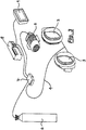
- FIG. 3 illustrates - in a very schematic form - an embodiment of the invention.
- the portholes 3 are connected to a gas supply/evacuation line 4 that is provided for the purpose of evacuating air from the sleeves, and for refilling the sleeves with a suitable gas as part of a conventional gas evacuation/refilling cycle.
- the gas supply/evacuation line 4 is part of a gas supply/evacuation system that further includes a vacuum pump 5 for evacuating gas, a gas cylinder 6 for providing a neutral gas for a gas refilling step, a pressure sensor and valve unit 7 for sensing pressure in the system and provided with valves for connecting the line 4 either to the gas cylinder 6 or the vacuum pump 5 as required.
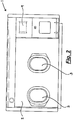
- the system further includes microprocessor control means 8 and a visual display unit 9. Visual display unit 9 will be provided at a suitable location on the front of a workstation where it can easily be seen by a user as shown for example in Figure 2 .
- Control means 8 provides control signals to the pressure sensor and valve unit 7
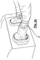
- Figures 4(a)-(d) show how the system of Figure 3 can be used to start and control a gas evacuation/refilling cycle. It should be noted that in these figures the sleeves 11 are shown as if transparent, but this is simply for clarity of illustration so that the hands within the sleeves can be seen. In practice while the sleeves could be formed of a transparent material that is not necessary and may be unlikely.
- a user will begin by placing their hands 10 within the sleeves 11 in a conventional manner.
- the sleeves 11 are formed with sealing means 12 that engage the user's forearms to form a substantially airtight seal around the wrist or forearm.
- the user may then move their hands away from the portholes 3 such that the sleeves 11 are fully extended away from the portholes 3 while remaining in airtight engagement with the portholes 3 and the wrists or forearms of the user.
- This position is shown in Figure 4(b) .
- the user may then form their hands 10 into a fist and then as shown in Figure 4(d) will move their fists 10 toward the portholes 3.
- the processing means 8 may, for example, be programmed to recognise that an increase of pressure above a certain level, with the increase taking place within a given short time period, is indicative of the presence of a user ready to commence and the processing means 8 may thus signal the pressure sensor and valve unit 7 to commence a gas evacuation and refilling cycle.
- the system will preferably be calibrated such that only pressure increases above a predetermined level and/or for a predetermined time will initiate the cycle.
- the system may require a user to generate two successive increases of pressure, e.g. by repeating the movement of the fist towards the porthole, and/or may require the increase in pressure to be rapid which could only be caused by a rapid movement of the hands of the user, preferably in the form of fists, towards the porthole.
- the system is capable of detecting that a user is ready to commence using the workstation 1 and that a gas evacuation/refilling cycle should be initiated. This is done by detecting the presence of a user's hands within the sleeves by detecting a pressure change in the system.
Landscapes
- Engineering & Computer Science (AREA)
- Chemical & Material Sciences (AREA)
- Health & Medical Sciences (AREA)
- Mechanical Engineering (AREA)
- Robotics (AREA)
- Chemical Kinetics & Catalysis (AREA)
- Clinical Laboratory Science (AREA)
- Organic Chemistry (AREA)
- Life Sciences & Earth Sciences (AREA)
- Bioinformatics & Cheminformatics (AREA)
- Wood Science & Technology (AREA)
- Zoology (AREA)
- Biomedical Technology (AREA)
- Biotechnology (AREA)
- General Health & Medical Sciences (AREA)
- Genetics & Genomics (AREA)
- Biochemistry (AREA)
- Sustainable Development (AREA)
- Microbiology (AREA)
- General Engineering & Computer Science (AREA)
- Analytical Chemistry (AREA)
- Respiratory Apparatuses And Protective Means (AREA)
- Filling Or Discharging Of Gas Storage Vessels (AREA)
- Sampling And Sample Adjustment (AREA)
- Pressure Vessels And Lids Thereof (AREA)
- Circuit Breakers (AREA)
- Apparatus Associated With Microorganisms And Enzymes (AREA)
Description
- This invention relates to a controlled atmosphere workstation such as, for example, an anaerobic workstation such as used or intended for use in microbiological laboratories. In particular the invention relates to a method for initiating a sleeve evacuation process and to a workstation designed to operate such a method.
- A controlled atmosphere workstation provides a workstation in which microbiological experiments can be performed in a controlled atmosphere. Generally the atmosphere will differ in some form - usually in composition and in particular in the amount of oxygen - from ambient conditions and in such cases the controlled atmosphere may be considered a modified atmosphere. An anaerobic workstation, for example, will have an oxygen content that is reduced compared with ambient conditions possibly down to zero or as close to zero as can practically be achieved. In addition to gas contents, the temperature, humidity and pressure of the atmosphere within the workstation can also be controlled.
- To perform meaningful microbiological experiments in such a workstation it is necessary for a user to be able to use their hands within the workstation in order to perform various actions. To this end a workstation is normally provided with a number of access ports - usually at least two - through which an arm can be inserted and which are designed to allow a user to insert his or her arm into the workstation and then subsequently withdraw the arm without allowing ambient air into the workstation compromising conditions inside the workstation, and without allowing the atmosphere within the workstation to escape to atmosphere in an uncontrolled manner. In other words the access ports must be designed so that the seal between the ambient atmosphere and the modified atmosphere in the workstation is not broken when a user inserts and removes an arm.
- One known way of achieving this is to use a sleeve which is fixed in a sealed manner to the access port and into which a user inserts his arm. In such a design after a user inserts his/her arm into the sleeve and before the access port can be opened, air must be extracted from within the sleeve and optionally replaced with either a neutral gas or with the same gas that supplies the workstation itself. Optionally this gas extraction/refilling cycle may be carried out twice or more before the access port itself can be opened in order to minimise any risk of compromising internal environmental conditions.
- This extraction/refilling cycle can of course only be carried out once a user's arm is in the sleeve, and since a user will generally be inserting both arms through respective sleeves the user will normally have no hand free to press any button to start the process. It is therefore conventional to provide one or more foot-operated switches that initiate the gas extraction/refilling cycle(s). Such foot-operated switches may be connected by a cable to the workstation control means or may operate wirelessly. However, wireless operation can be problematic in some laboratories where there may be restrictions on the use of wireless technologies to prevent electrical interference, and whether the foot-operated switches are wireless or wired they represent additional cost. Some users find foot switches inconvenient, may not like them and may not operate them correctly. Japanese Patent
JP 2857209 B2 - According to the present invention there is provided a controlled atmosphere workstation comprising, a chamber, at least one porthole that may be opened for enabling a user to access the chamber, a sleeve secured to the said at least one porthole, said sleeve being adapted in use to receive the hand and of a user and to engage the forearm of a user, and a system for evacuating the sleeve prior to opening the porthole, wherein operation of said sleeve evacuation system is initiated by said hand within the sleeve.
- Particularly, the operation of the sleeve evacuation system is initiated by movement of the hand towards the porthole.
- In the present invention the workstation comprises means for detecting changes in air pressure in the vicinity of the porthole when the hand moves towards the porthole, and wherein the sleeve evacuation system is initiated by detecting a change in the pressure. Preferably the sleeve evacuation system is initiated by detecting a change in the pressure above a predetermined level and/or within a predetermined time interval.
- According to another aspect of the present invention there is provided a method for initiating a sleeve evacuation process in a controlled atmosphere workstation comprising a chamber, at least one porthole that may be opened for enabling a user to access the chamber, and a sleeve secured to the at least one porthole, the method comprising placing the hand of a user within the sleeve with the sleeve engaging the forearm of the user, and initiating the sleeve evacuation process in response to the hand and forearm within the sleeve.
- In the present invention, the sleeve evacuation process is initiated by movement of the hand towards the at least one porthole. For example, the sleeve evacuation process is initiated by detecting a pressure change in the vicinity of the porthole when said hand is moved towards said at least one porthole. Preferably the sleeve evacuation system is initiated by detecting a change in pressure above a predetermined level and/or within a predetermined time interval.
- Some embodiments of the invention will now be described by way of example and with reference to the accompanying drawings, in which:-
-
Figure 1 is a perspective view of a workstation; -
Figure 2 is a front view of a workstation; -
Figure 3 is a detailed view of the portholes of the workstation offigures 1 and2 ; and -
Figures 4(a) to 4(d) illustrate the sequence of operation of an embodiment of the invention. - Referring firstly to
Figures 1 and2 there is shown in general terms a controlled atmosphere workstation such as an anaerobic workstation 1. Such workstations are generally well-known and need not be described in detail, but they will include a workingchamber 2 in which microbiological samples can be held under specific atmospheric conditions and in which certain microbiological operations can be carried out. The chamber is provided with at least oneporthole 3 and preferably two ormore portholes 3 through which an operator can insert his/her hands in order to carry out operations inside thechamber 2. The manner in which an operator inserts his/her hands into thechamber 2 without compromising the controlled atmosphere will be described in more detail below. Conventionally the workstation 1 is mounted either on a trolley (not shown) or on a work surface so that an operator will stand in front of the workstation 1 and can place his hands through theportholes 3 and carry out operations within thechamber 2 without having to bend or be in an uncomfortable position. Theportholes 3 are provided with porthole doors (not shown) that may be opened by an operator to enable access into thechamber 2 of the workstation 1. - It will be understood that the size of the workstation 1, and in particular the number of
portholes 3, can take any known form. - The workstation 1 is designed such that the atmosphere within the
chamber 2 can be controlled to be something other than ambient. For example, the atmosphere can be controlled in terms of its chemical composition (for example it may be anaerobic), and/or the pressure, temperature and humidity may be controlled so as to be something other than the ambient conditions in the laboratory in which the workstation 1 is located. At the same time it is necessary to enable a laboratory technician to work within the workstation 1 by at a minimum placing and removing samples into and from the workstation and since in some cases it is necessary for a technician to carry out more delicate of complicated procedures within the workstation 1, it is particularly preferred that a technician be able to insert uncovered hands into the workstation 1 so that he or she can properly handle items and carry out any necessary tasks. Of course this needs to be possible without compromising the atmospheric conditions within the workstation 1. - One known way that enables an operator to insert bare hands (and indeed forearms) into the workstation 1 without compromising the atmospheric conditions within the workstation involves the use of sealing sleeves that are secured to a flange extending around the porthole. The sleeves are conventional in design and may be formed of known materials including rubber, or synthetic materials. In use a technician inserts his or her arms into the sleeves the open ends of which are provided with a sealing means that engages the technician's wrists or forearms. Once the technician's arms are received within the sleeves the technician initiates an evacuation/gas refilling cycle in which first all air is extracted from the sleeves and then the sleeves are refilled with a neutral flushing gas. This cycle may be repeated more than once and when completed the technician is able to open the porthole door to provide access to the chamber of the workstation 1 and the technician can insert his or her hands and forearms into the chamber.
- Because the technician's arms are within the sleeves during this evacuation/re-filling cycle, some means needs to be provided to allow the technician to start the evacuation/re-filling cycle. Conventionally this is done by operation of a footswitch but the present invention, at least in its preferred embodiments, aims to provide a more convenient and user-friendly alternative as will now be described.
-
Figure 3 illustrates - in a very schematic form - an embodiment of the invention. Theportholes 3 are connected to a gas supply/evacuation line 4 that is provided for the purpose of evacuating air from the sleeves, and for refilling the sleeves with a suitable gas as part of a conventional gas evacuation/refilling cycle. The gas supply/evacuation line 4 is part of a gas supply/evacuation system that further includes avacuum pump 5 for evacuating gas, a gas cylinder 6 for providing a neutral gas for a gas refilling step, a pressure sensor andvalve unit 7 for sensing pressure in the system and provided with valves for connecting the line 4 either to the gas cylinder 6 or thevacuum pump 5 as required. The system further includes microprocessor control means 8 and a visual display unit 9. Visual display unit 9 will be provided at a suitable location on the front of a workstation where it can easily be seen by a user as shown for example inFigure 2 . Control means 8 provides control signals to the pressure sensor andvalve unit 7 and receives pressure data therefrom. -
Figures 4(a)-(d) show how the system ofFigure 3 can be used to start and control a gas evacuation/refilling cycle. It should be noted that in these figures thesleeves 11 are shown as if transparent, but this is simply for clarity of illustration so that the hands within the sleeves can be seen. In practice while the sleeves could be formed of a transparent material that is not necessary and may be unlikely. - As shown in
Figure 4(a) a user will begin by placing theirhands 10 within thesleeves 11 in a conventional manner. Thesleeves 11 are formed with sealing means 12 that engage the user's forearms to form a substantially airtight seal around the wrist or forearm. The user may then move their hands away from theportholes 3 such that thesleeves 11 are fully extended away from theportholes 3 while remaining in airtight engagement with theportholes 3 and the wrists or forearms of the user. This position is shown inFigure 4(b) . As shown inFigure 4(c) the user may then form theirhands 10 into a fist and then as shown inFigure 4(d) will move theirfists 10 toward theportholes 3. Doing so will create an increase in the pressure in the line 4 that may be detected by the pressure sensor andvalve unit 7. Forming the hands into fists may not be necessary, but doing so causes the increase in pressure to be more clearly defined. This sudden increase in pressure can be used as a signal to indicate that a user is ready to use the workstation 1 and wishes to commence a gas evacuation/refilling cycle before entering thechamber 2. The processing means 8 may, for example, be programmed to recognise that an increase of pressure above a certain level, with the increase taking place within a given short time period, is indicative of the presence of a user ready to commence and the processing means 8 may thus signal the pressure sensor andvalve unit 7 to commence a gas evacuation and refilling cycle. It will be important to ensure that a gas evacuation/refilling cycle is not started in error by a false signal and thus the system will preferably be calibrated such that only pressure increases above a predetermined level and/or for a predetermined time will initiate the cycle. As a further precaution, the system may require a user to generate two successive increases of pressure, e.g. by repeating the movement of the fist towards the porthole, and/or may require the increase in pressure to be rapid which could only be caused by a rapid movement of the hands of the user, preferably in the form of fists, towards the porthole. - Once the gas evacuation/refilling cycle has commenced this will be displayed on the visual display unit 9 which will show the status of the cycle and will indicate to the user when the cycle has been completed the
portholes 3 may be opened. - It will thus be seen that the system is capable of detecting that a user is ready to commence using the workstation 1 and that a gas evacuation/refilling cycle should be initiated. This is done by detecting the presence of a user's hands within the sleeves by detecting a pressure change in the system.
- It will thus be understood that at least in preferred embodiments of the invention there is provided a controlled atmosphere workstation in which a gas evacuation/refilling cycle can be initiated by a user in a particularly simple and convenient manner.
Claims (4)
- A controlled atmosphere workstation (1) comprising, a chamber (2), at least one porthole (3) that may be opened for enabling a user to access the chamber, a sleeve (11) secured to the said at least one porthole, said sleeve being adapted in use to receive the hand of a user and to engage the forearm of a user, a system for evacuating the sleeve prior to opening the porthole, and means for detecting changes in air pressure in the vicinity of said porthole when said hand is moved towards said porthole, and characterised in that operation of said sleeve evacuation system is initiated by detecting a change in said pressure due to the movement of said hand towards said porthole.
- A workstation as claimed in claim 1 wherein said sleeve evacuation system is initiated by detecting a change in said pressure above a predetermined level and/or within a predetermined time interval.
- A method for initiating a sleeve evacuation process in a controlled atmosphere workstation (1) comprising a chamber (2), at least one porthole (3) that may be opened for enabling a user to access the chamber, and a sleeve (11) secured to the said at least one porthole, said method comprising placing the hand of a user within said sleeve with the sleeve engaging the forearm of the user, and initiating the sleeve evacuation process by detecting a pressure change in the vicinity of said at least one porthole when said hand is moved towards said at least one porthole.
- A method as claimed in claim 3 wherein said sleeve evacuation system is initiated by detecting a change in said pressure above a predetermined level and/or within a predetermined time interval.
Applications Claiming Priority (1)
| Application Number | Priority Date | Filing Date | Title |
|---|---|---|---|
| GB1302880.8A GB2512277B (en) | 2013-02-19 | 2013-02-19 | Controlled atmosphere workstation |
Publications (3)
| Publication Number | Publication Date |
|---|---|
| EP2767338A2 EP2767338A2 (en) | 2014-08-20 |
| EP2767338A3 EP2767338A3 (en) | 2016-01-06 |
| EP2767338B1 true EP2767338B1 (en) | 2017-12-06 |
Family
ID=48048606
Family Applications (1)
| Application Number | Title | Priority Date | Filing Date |
|---|---|---|---|
| EP14154139.1A Not-in-force EP2767338B1 (en) | 2013-02-19 | 2014-02-06 | Controlled atmosphere workstation |
Country Status (3)
| Country | Link |
|---|---|
| US (1) | US10086520B2 (en) |
| EP (1) | EP2767338B1 (en) |
| GB (1) | GB2512277B (en) |
Families Citing this family (4)
| Publication number | Priority date | Publication date | Assignee | Title |
|---|---|---|---|---|
| FR3025450B1 (en) * | 2014-09-08 | 2016-12-23 | Thales Sa | REPAIR UNIT FOR NACELLE |
| MX2018006687A (en) * | 2015-12-01 | 2018-11-09 | Clean Air Essentials 797 Inc | Isolator sleeve systems. |
| DE102018209249A1 (en) * | 2018-06-11 | 2019-12-12 | Robert Bosch Gmbh | Safety device of a glove neck |
| US12011826B1 (en) * | 2021-04-27 | 2024-06-18 | Flow Sciences, Inc. | Negative pressure glovebox having multifunctional air diverter |
Family Cites Families (13)
| Publication number | Priority date | Publication date | Assignee | Title |
|---|---|---|---|---|
| US2695605A (en) * | 1949-12-12 | 1954-11-30 | Philadelphia Children Hospital | Closure device for isolation chambers |
| US3051163A (en) * | 1957-05-01 | 1962-08-28 | Univ Notre Dame Du Lac | Isolating device |
| US3337279A (en) * | 1965-01-12 | 1967-08-22 | Reinhardt Gustav | Gas purged dry box glove |
| US3356254A (en) * | 1965-07-30 | 1967-12-05 | Walter W Becker | Glove port for dry box |
| US3907389A (en) * | 1973-12-12 | 1975-09-23 | Marion E Cox | Glove box chamber |
| JPS58501311A (en) * | 1981-08-24 | 1983-08-11 | フルコ | medical cleaning equipment |
| JPS60146471A (en) * | 1984-01-06 | 1985-08-02 | Japan Storage Battery Co Ltd | Specific gravity detection apparatus for lead storage battery |
| GB8916578D0 (en) * | 1989-07-20 | 1989-09-06 | Foster William J | Anaerobic cabinet |
| JP2857209B2 (en) * | 1990-02-23 | 1999-02-17 | タバイエスペック株式会社 | Non-air atmosphere tester |
| EP0456420A1 (en) * | 1990-05-07 | 1991-11-13 | Hortotec( Ireland) Limited | A safety cabinet |
| DE69504087T2 (en) * | 1994-10-08 | 1998-12-10 | Don Whitley Scientific Ltd., Shipley, West Yorkshire | ANAEROBIC CABINET AND SYSTEM |
| US6100083A (en) * | 1999-03-16 | 2000-08-08 | Coy Laboratory Products, Inc. | Anaerobic chamber with collapsible diaphragm |
| CA2820789C (en) * | 2010-12-07 | 2017-02-28 | Brian Graydon | An apparatus for drying and sanitizing hands |
-
2013
- 2013-02-19 GB GB1302880.8A patent/GB2512277B/en not_active Expired - Fee Related
-
2014
- 2014-02-06 EP EP14154139.1A patent/EP2767338B1/en not_active Not-in-force
- 2014-02-12 US US14/178,471 patent/US10086520B2/en active Active
Non-Patent Citations (1)
| Title |
|---|
| None * |
Also Published As
| Publication number | Publication date |
|---|---|
| GB201302880D0 (en) | 2013-04-03 |
| US10086520B2 (en) | 2018-10-02 |
| GB2512277A (en) | 2014-10-01 |
| EP2767338A3 (en) | 2016-01-06 |
| GB2512277B (en) | 2016-12-14 |
| US20140232248A1 (en) | 2014-08-21 |
| EP2767338A2 (en) | 2014-08-20 |
Similar Documents
| Publication | Publication Date | Title |
|---|---|---|
| US10086520B2 (en) | Controlled atmosphere workstation | |
| US11040456B2 (en) | Robot operating apparatus provided with handles for operating robot | |
| CN104972473B (en) | With the people's coordination type industrial robot for introducing function | |
| CN103571740B (en) | A device integrating nucleic acid extraction, amplification and detection | |
| EP3900893B1 (en) | End effector and robot having the same | |
| WO2010085073A3 (en) | Surgical robot for liposuction | |
| WO2003067409A3 (en) | Device for inputting text by actuating keys of a numeric keypad for electronic devices and method for processing input impulses during text input | |
| JP2011247778A (en) | Specimen processing apparatus and rack transporting method | |
| CN103488278B (en) | A kind of control method and electronic equipment | |
| JP2021532909A (en) | Cookware and its control method | |
| JP2009279718A (en) | Method of conveying article from isolator and isolator | |
| JP5446574B2 (en) | Robot operating method and robot operating device | |
| US20150174592A1 (en) | Centrifuge | |
| KR200490149Y1 (en) | A reagent bottle shading and analysis device | |
| JP3850634B2 (en) | Controller | |
| CN115943020A (en) | Method and system for training a robot | |
| US6100083A (en) | Anaerobic chamber with collapsible diaphragm | |
| CN209538910U (en) | It is a kind of applied on Sterilized isolator with the door latch structure of warning function | |
| CN105245693B (en) | Pass through pressure touch and the mobile phone display screen curtain operating method and system of translation detection | |
| CN108851968B (en) | Cooking utensils | |
| JP2014184541A (en) | Arm operation method and arm operation device | |
| JP4212108B1 (en) | Disposable stopper block for blood collection tube and stopper device using the same | |
| JP2018530477A (en) | Device for mounting processing vessels | |
| CN207595556U (en) | A kind of interim placing box of blood to be detected | |
| US8950617B2 (en) | Non-penetrative blood container and apparatus for vacuuming the same |
Legal Events
| Date | Code | Title | Description |
|---|---|---|---|
| PUAI | Public reference made under article 153(3) epc to a published international application that has entered the european phase |
Free format text: ORIGINAL CODE: 0009012 |
|
| 17P | Request for examination filed |
Effective date: 20140206 |
|
| AK | Designated contracting states |
Kind code of ref document: A2 Designated state(s): AL AT BE BG CH CY CZ DE DK EE ES FI FR GB GR HR HU IE IS IT LI LT LU LV MC MK MT NL NO PL PT RO RS SE SI SK SM TR |
|
| AX | Request for extension of the european patent |
Extension state: BA ME |
|
| PUAL | Search report despatched |
Free format text: ORIGINAL CODE: 0009013 |
|
| AK | Designated contracting states |
Kind code of ref document: A3 Designated state(s): AL AT BE BG CH CY CZ DE DK EE ES FI FR GB GR HR HU IE IS IT LI LT LU LV MC MK MT NL NO PL PT RO RS SE SI SK SM TR |
|
| AX | Request for extension of the european patent |
Extension state: BA ME |
|
| RIC1 | Information provided on ipc code assigned before grant |
Ipc: B01L 1/02 20060101AFI20151130BHEP Ipc: B25J 21/02 20060101ALI20151130BHEP Ipc: B25J 1/00 20060101ALI20151130BHEP |
|
| R17P | Request for examination filed (corrected) |
Effective date: 20160704 |
|
| RBV | Designated contracting states (corrected) |
Designated state(s): AL AT BE BG CH CY CZ DE DK EE ES FI FR GB GR HR HU IE IS IT LI LT LU LV MC MK MT NL NO PL PT RO RS SE SI SK SM TR |
|
| R17P | Request for examination filed (corrected) |
Effective date: 20160704 |
|
| 17Q | First examination report despatched |
Effective date: 20170316 |
|
| GRAP | Despatch of communication of intention to grant a patent |
Free format text: ORIGINAL CODE: EPIDOSNIGR1 |
|
| INTG | Intention to grant announced |
Effective date: 20170623 |
|
| GRAS | Grant fee paid |
Free format text: ORIGINAL CODE: EPIDOSNIGR3 |
|
| GRAA | (expected) grant |
Free format text: ORIGINAL CODE: 0009210 |
|
| AK | Designated contracting states |
Kind code of ref document: B1 Designated state(s): AL AT BE BG CH CY CZ DE DK EE ES FI FR GB GR HR HU IE IS IT LI LT LU LV MC MK MT NL NO PL PT RO RS SE SI SK SM TR |
|
| REG | Reference to a national code |
Ref country code: GB Ref legal event code: FG4D |
|
| REG | Reference to a national code |
Ref country code: AT Ref legal event code: REF Ref document number: 951897 Country of ref document: AT Kind code of ref document: T Effective date: 20171215 Ref country code: CH Ref legal event code: EP |
|
| REG | Reference to a national code |
Ref country code: IE Ref legal event code: FG4D |
|
| REG | Reference to a national code |
Ref country code: DE Ref legal event code: R096 Ref document number: 602014018076 Country of ref document: DE |
|
| REG | Reference to a national code |
Ref country code: NL Ref legal event code: MP Effective date: 20171206 |
|
| REG | Reference to a national code |
Ref country code: LT Ref legal event code: MG4D |
|
| PG25 | Lapsed in a contracting state [announced via postgrant information from national office to epo] |
Ref country code: LT Free format text: LAPSE BECAUSE OF FAILURE TO SUBMIT A TRANSLATION OF THE DESCRIPTION OR TO PAY THE FEE WITHIN THE PRESCRIBED TIME-LIMIT Effective date: 20171206 Ref country code: FI Free format text: LAPSE BECAUSE OF FAILURE TO SUBMIT A TRANSLATION OF THE DESCRIPTION OR TO PAY THE FEE WITHIN THE PRESCRIBED TIME-LIMIT Effective date: 20171206 Ref country code: NO Free format text: LAPSE BECAUSE OF FAILURE TO SUBMIT A TRANSLATION OF THE DESCRIPTION OR TO PAY THE FEE WITHIN THE PRESCRIBED TIME-LIMIT Effective date: 20180306 Ref country code: ES Free format text: LAPSE BECAUSE OF FAILURE TO SUBMIT A TRANSLATION OF THE DESCRIPTION OR TO PAY THE FEE WITHIN THE PRESCRIBED TIME-LIMIT Effective date: 20171206 Ref country code: SE Free format text: LAPSE BECAUSE OF FAILURE TO SUBMIT A TRANSLATION OF THE DESCRIPTION OR TO PAY THE FEE WITHIN THE PRESCRIBED TIME-LIMIT Effective date: 20171206 |
|
| REG | Reference to a national code |
Ref country code: AT Ref legal event code: MK05 Ref document number: 951897 Country of ref document: AT Kind code of ref document: T Effective date: 20171206 |
|
| PG25 | Lapsed in a contracting state [announced via postgrant information from national office to epo] |
Ref country code: BG Free format text: LAPSE BECAUSE OF FAILURE TO SUBMIT A TRANSLATION OF THE DESCRIPTION OR TO PAY THE FEE WITHIN THE PRESCRIBED TIME-LIMIT Effective date: 20180306 Ref country code: HR Free format text: LAPSE BECAUSE OF FAILURE TO SUBMIT A TRANSLATION OF THE DESCRIPTION OR TO PAY THE FEE WITHIN THE PRESCRIBED TIME-LIMIT Effective date: 20171206 Ref country code: RS Free format text: LAPSE BECAUSE OF FAILURE TO SUBMIT A TRANSLATION OF THE DESCRIPTION OR TO PAY THE FEE WITHIN THE PRESCRIBED TIME-LIMIT Effective date: 20171206 Ref country code: GR Free format text: LAPSE BECAUSE OF FAILURE TO SUBMIT A TRANSLATION OF THE DESCRIPTION OR TO PAY THE FEE WITHIN THE PRESCRIBED TIME-LIMIT Effective date: 20180307 Ref country code: LV Free format text: LAPSE BECAUSE OF FAILURE TO SUBMIT A TRANSLATION OF THE DESCRIPTION OR TO PAY THE FEE WITHIN THE PRESCRIBED TIME-LIMIT Effective date: 20171206 |
|
| PG25 | Lapsed in a contracting state [announced via postgrant information from national office to epo] |
Ref country code: NL Free format text: LAPSE BECAUSE OF FAILURE TO SUBMIT A TRANSLATION OF THE DESCRIPTION OR TO PAY THE FEE WITHIN THE PRESCRIBED TIME-LIMIT Effective date: 20171206 |
|
| PG25 | Lapsed in a contracting state [announced via postgrant information from national office to epo] |
Ref country code: SK Free format text: LAPSE BECAUSE OF FAILURE TO SUBMIT A TRANSLATION OF THE DESCRIPTION OR TO PAY THE FEE WITHIN THE PRESCRIBED TIME-LIMIT Effective date: 20171206 Ref country code: CZ Free format text: LAPSE BECAUSE OF FAILURE TO SUBMIT A TRANSLATION OF THE DESCRIPTION OR TO PAY THE FEE WITHIN THE PRESCRIBED TIME-LIMIT Effective date: 20171206 Ref country code: EE Free format text: LAPSE BECAUSE OF FAILURE TO SUBMIT A TRANSLATION OF THE DESCRIPTION OR TO PAY THE FEE WITHIN THE PRESCRIBED TIME-LIMIT Effective date: 20171206 |
|
| PG25 | Lapsed in a contracting state [announced via postgrant information from national office to epo] |
Ref country code: SM Free format text: LAPSE BECAUSE OF FAILURE TO SUBMIT A TRANSLATION OF THE DESCRIPTION OR TO PAY THE FEE WITHIN THE PRESCRIBED TIME-LIMIT Effective date: 20171206 Ref country code: PL Free format text: LAPSE BECAUSE OF FAILURE TO SUBMIT A TRANSLATION OF THE DESCRIPTION OR TO PAY THE FEE WITHIN THE PRESCRIBED TIME-LIMIT Effective date: 20171206 Ref country code: RO Free format text: LAPSE BECAUSE OF FAILURE TO SUBMIT A TRANSLATION OF THE DESCRIPTION OR TO PAY THE FEE WITHIN THE PRESCRIBED TIME-LIMIT Effective date: 20171206 Ref country code: IT Free format text: LAPSE BECAUSE OF FAILURE TO SUBMIT A TRANSLATION OF THE DESCRIPTION OR TO PAY THE FEE WITHIN THE PRESCRIBED TIME-LIMIT Effective date: 20171206 Ref country code: AT Free format text: LAPSE BECAUSE OF FAILURE TO SUBMIT A TRANSLATION OF THE DESCRIPTION OR TO PAY THE FEE WITHIN THE PRESCRIBED TIME-LIMIT Effective date: 20171206 |
|
| REG | Reference to a national code |
Ref country code: DE Ref legal event code: R097 Ref document number: 602014018076 Country of ref document: DE |
|
| REG | Reference to a national code |
Ref country code: CH Ref legal event code: PL |
|
| PG25 | Lapsed in a contracting state [announced via postgrant information from national office to epo] |
Ref country code: MC Free format text: LAPSE BECAUSE OF FAILURE TO SUBMIT A TRANSLATION OF THE DESCRIPTION OR TO PAY THE FEE WITHIN THE PRESCRIBED TIME-LIMIT Effective date: 20171206 |
|
| PLBE | No opposition filed within time limit |
Free format text: ORIGINAL CODE: 0009261 |
|
| STAA | Information on the status of an ep patent application or granted ep patent |
Free format text: STATUS: NO OPPOSITION FILED WITHIN TIME LIMIT |
|
| 26N | No opposition filed |
Effective date: 20180907 |
|
| REG | Reference to a national code |
Ref country code: IE Ref legal event code: MM4A |
|
| REG | Reference to a national code |
Ref country code: BE Ref legal event code: MM Effective date: 20180228 |
|
| PG25 | Lapsed in a contracting state [announced via postgrant information from national office to epo] |
Ref country code: DK Free format text: LAPSE BECAUSE OF FAILURE TO SUBMIT A TRANSLATION OF THE DESCRIPTION OR TO PAY THE FEE WITHIN THE PRESCRIBED TIME-LIMIT Effective date: 20171206 Ref country code: LU Free format text: LAPSE BECAUSE OF NON-PAYMENT OF DUE FEES Effective date: 20180206 Ref country code: SI Free format text: LAPSE BECAUSE OF FAILURE TO SUBMIT A TRANSLATION OF THE DESCRIPTION OR TO PAY THE FEE WITHIN THE PRESCRIBED TIME-LIMIT Effective date: 20171206 Ref country code: LI Free format text: LAPSE BECAUSE OF NON-PAYMENT OF DUE FEES Effective date: 20180228 Ref country code: CH Free format text: LAPSE BECAUSE OF NON-PAYMENT OF DUE FEES Effective date: 20180228 |
|
| REG | Reference to a national code |
Ref country code: FR Ref legal event code: ST Effective date: 20181031 |
|
| PG25 | Lapsed in a contracting state [announced via postgrant information from national office to epo] |
Ref country code: IE Free format text: LAPSE BECAUSE OF NON-PAYMENT OF DUE FEES Effective date: 20180206 |
|
| PG25 | Lapsed in a contracting state [announced via postgrant information from national office to epo] |
Ref country code: BE Free format text: LAPSE BECAUSE OF NON-PAYMENT OF DUE FEES Effective date: 20180228 Ref country code: FR Free format text: LAPSE BECAUSE OF NON-PAYMENT OF DUE FEES Effective date: 20180228 |
|
| REG | Reference to a national code |
Ref country code: DE Ref legal event code: R082 Ref document number: 602014018076 Country of ref document: DE Representative=s name: HASELTINE LAKE KEMPNER LLP, DE Ref country code: DE Ref legal event code: R083 Ref document number: 602014018076 Country of ref document: DE Ref country code: DE Ref legal event code: R081 Ref document number: 602014018076 Country of ref document: DE Owner name: DON WHITLEY SCIENTIFIC LIMITED, BINGLEY, GB Free format text: FORMER OWNER: DON WHITLEY SCIENTIFIC LTD., SHIPLEY, WEST YORKSHIRE, GB Ref country code: DE Ref legal event code: R082 Ref document number: 602014018076 Country of ref document: DE Representative=s name: HL KEMPNER PATENTANWALT, RECHTSANWALT, SOLICIT, DE |
|
| PG25 | Lapsed in a contracting state [announced via postgrant information from national office to epo] |
Ref country code: MT Free format text: LAPSE BECAUSE OF NON-PAYMENT OF DUE FEES Effective date: 20180206 |
|
| PG25 | Lapsed in a contracting state [announced via postgrant information from national office to epo] |
Ref country code: TR Free format text: LAPSE BECAUSE OF FAILURE TO SUBMIT A TRANSLATION OF THE DESCRIPTION OR TO PAY THE FEE WITHIN THE PRESCRIBED TIME-LIMIT Effective date: 20171206 |
|
| PGFP | Annual fee paid to national office [announced via postgrant information from national office to epo] |
Ref country code: GB Payment date: 20200221 Year of fee payment: 7 |
|
| PG25 | Lapsed in a contracting state [announced via postgrant information from national office to epo] |
Ref country code: PT Free format text: LAPSE BECAUSE OF FAILURE TO SUBMIT A TRANSLATION OF THE DESCRIPTION OR TO PAY THE FEE WITHIN THE PRESCRIBED TIME-LIMIT Effective date: 20171206 Ref country code: HU Free format text: LAPSE BECAUSE OF FAILURE TO SUBMIT A TRANSLATION OF THE DESCRIPTION OR TO PAY THE FEE WITHIN THE PRESCRIBED TIME-LIMIT; INVALID AB INITIO Effective date: 20140206 |
|
| PG25 | Lapsed in a contracting state [announced via postgrant information from national office to epo] |
Ref country code: CY Free format text: LAPSE BECAUSE OF FAILURE TO SUBMIT A TRANSLATION OF THE DESCRIPTION OR TO PAY THE FEE WITHIN THE PRESCRIBED TIME-LIMIT Effective date: 20171206 Ref country code: MK Free format text: LAPSE BECAUSE OF NON-PAYMENT OF DUE FEES Effective date: 20171206 |
|
| PG25 | Lapsed in a contracting state [announced via postgrant information from national office to epo] |
Ref country code: AL Free format text: LAPSE BECAUSE OF FAILURE TO SUBMIT A TRANSLATION OF THE DESCRIPTION OR TO PAY THE FEE WITHIN THE PRESCRIBED TIME-LIMIT Effective date: 20171206 Ref country code: IS Free format text: LAPSE BECAUSE OF FAILURE TO SUBMIT A TRANSLATION OF THE DESCRIPTION OR TO PAY THE FEE WITHIN THE PRESCRIBED TIME-LIMIT Effective date: 20180406 |
|
| PGFP | Annual fee paid to national office [announced via postgrant information from national office to epo] |
Ref country code: DE Payment date: 20200221 Year of fee payment: 7 |
|
| REG | Reference to a national code |
Ref country code: DE Ref legal event code: R082 Ref document number: 602014018076 Country of ref document: DE Representative=s name: HL KEMPNER PATENTANWALT, RECHTSANWALT, SOLICIT, DE |
|
| REG | Reference to a national code |
Ref country code: DE Ref legal event code: R119 Ref document number: 602014018076 Country of ref document: DE |
|
| GBPC | Gb: european patent ceased through non-payment of renewal fee |
Effective date: 20210206 |
|
| PG25 | Lapsed in a contracting state [announced via postgrant information from national office to epo] |
Ref country code: GB Free format text: LAPSE BECAUSE OF NON-PAYMENT OF DUE FEES Effective date: 20210206 Ref country code: DE Free format text: LAPSE BECAUSE OF NON-PAYMENT OF DUE FEES Effective date: 20210901 |