EP0456420A1 - A safety cabinet - Google Patents
A safety cabinet Download PDFInfo
- Publication number
- EP0456420A1 EP0456420A1 EP91303996A EP91303996A EP0456420A1 EP 0456420 A1 EP0456420 A1 EP 0456420A1 EP 91303996 A EP91303996 A EP 91303996A EP 91303996 A EP91303996 A EP 91303996A EP 0456420 A1 EP0456420 A1 EP 0456420A1
- Authority
- EP
- European Patent Office
- Prior art keywords
- housing
- working chamber
- communicating
- air
- safety cabinet
- Prior art date
- Legal status (The legal status is an assumption and is not a legal conclusion. Google has not performed a legal analysis and makes no representation as to the accuracy of the status listed.)
- Withdrawn
Links
Images


Classifications
-
- B—PERFORMING OPERATIONS; TRANSPORTING
- B01—PHYSICAL OR CHEMICAL PROCESSES OR APPARATUS IN GENERAL
- B01L—CHEMICAL OR PHYSICAL LABORATORY APPARATUS FOR GENERAL USE
- B01L1/00—Enclosures; Chambers
- B01L1/04—Dust-free rooms or enclosures
-
- B—PERFORMING OPERATIONS; TRANSPORTING
- B25—HAND TOOLS; PORTABLE POWER-DRIVEN TOOLS; MANIPULATORS
- B25J—MANIPULATORS; CHAMBERS PROVIDED WITH MANIPULATION DEVICES
- B25J21/00—Chambers provided with manipulation devices
- B25J21/02—Glove-boxes, i.e. chambers in which manipulations are performed by the human hands in gloves built into the chamber walls; Gloves therefor
-
- F—MECHANICAL ENGINEERING; LIGHTING; HEATING; WEAPONS; BLASTING
- F24—HEATING; RANGES; VENTILATING
- F24F—AIR-CONDITIONING; AIR-HUMIDIFICATION; VENTILATION; USE OF AIR CURRENTS FOR SCREENING
- F24F3/00—Air-conditioning systems in which conditioned primary air is supplied from one or more central stations to distributing units in the rooms or spaces where it may receive secondary treatment; Apparatus specially designed for such systems
- F24F3/12—Air-conditioning systems in which conditioned primary air is supplied from one or more central stations to distributing units in the rooms or spaces where it may receive secondary treatment; Apparatus specially designed for such systems characterised by the treatment of the air otherwise than by heating and cooling
- F24F3/16—Air-conditioning systems in which conditioned primary air is supplied from one or more central stations to distributing units in the rooms or spaces where it may receive secondary treatment; Apparatus specially designed for such systems characterised by the treatment of the air otherwise than by heating and cooling by purification, e.g. by filtering; by sterilisation; by ozonisation
- F24F3/167—Clean rooms, i.e. enclosed spaces in which a uniform flow of filtered air is distributed
Definitions
- the present invention relates to a safety cabinet of the type comprising a housing defining a working chamber within which a negative pressure is created relative to atmosphere.
- fume hoods and the like are provided in laboratories to protect an individual carrying out a test.
- hoods in general, are of relatively large size and are generally built in a fixed position in the laboratory. They are unsuitable for carrying out single experiments on a relatively small scale, and by virtue of the fact that they are fixed in the laboratory, it is necessary that the test should be carried out in the laboratory.
- the present invention is directed towards providing such a safety cabinet.
- the invention overcomes the problems of known devices by providing a safety cabinet which comprises a housing defining a working chamber within which a negative pressure is created relative to atmosphere, wherein the housing is portable, and the housing defines a substantially enclosed working chamber and is constructed at least partly of transparent material for facilitating visual inspection of the working chamber, and the cabinet comprises first port means communicating with the working chamber, second port means communicating with atmosphere, communicating means communicating the first port means and the second port means, air transfer means being provided in the communicating means for withdrawing air from the working chamber and delivering the air through the second port means for creating the negative pressure in the working chamber, main filter means being provided in the communicating means for filtering air passing through the communicating means, and access means being provided in the housing to the working chamber for accommodating a hand or the like.
- a particularly important advantage of the invention is that by virtue of the fact that the safety cabinet is portable, it can be moved from place to place either within a laboratory or indeed outside a laboratory for carrying out tests at any convenient location.
- the working chamber is substantially enclosed, the individual carrying out the test is protected from hazardous waste, fumes or the like from the material being tested.
- the air transfer means withdraws air from the working chamber and creates a negative pressure in the working chamber relative to atmosphere, the individual is protected from waste, fumes and the like from the material being tested. This is particularly important where a test is being carried out on a hazardous material.
- the filter means filters the air prior to being delivered from the second port means, the air being delivered to atmosphere has, in general, been cleaned and does not present a hazard.
- an individual carrying out the test can handle or manipulate the materials being tested while the test is in progress in the working chamber.
- the main filter means is mounted in the communicating means intermediate the air transfer means and the first port means.
- the advantage of this feature of the invention is that the air from the working chamber is filtered prior to reaching the air transfer means.
- the main filter means is a filter provided to British standard 5726:1978.
- the advantage of this feature of the invention is that it provides particularly good filtration of the air.
- the communicating means comprises a duct extending between the air transfer means and the first port means, the main filter means being releasably mounted in the duct, an opening being provided to the duct for replacing the main filter means, and a closure member releasably and sealably closing the said opening in the duct.
- a sensor means is provided in the communicating means for monitoring air flow through the communicating means for determining the condition of the main filter means, and alerting means are provided for indicating that the main filter means requires replacement, the alerting means being responsive to the sensor means.
- the air transfer means comprises a fan, the fan being driven by an electric motor.
- a control means for controlling the electric motor is provided, the control means being responsive to the sensor means for varying the speed of the motor in response to a variation in air velocity passing through the communicating means.
- the advantage of this feature of the invention is that it provides that air is drawn from the working chamber at a relatively constant rate.
- the access means comprises an access opening formed in the housing to the working chamber, and a sleeve extends from the access opening into the working chamber and sealably closes the access opening, the sleeve terminating in a glove.
- the advantage of this feature of the invention is that it provides a relatively convenient construction of cabinet, and furthermore, the individual carrying out the tests is isolated from the working chamber.
- the housing comprises third port means, the third port means communicating with the working chamber, and a secondary filter means being provided in the third port means.
- the housing comprises a main housing, and a support housing supporting the main housing, the main housing forming the working chamber and being of substantially spherical shape, the support housing housing the air transfer means and the main filter means.
- the cabinet 1 is of size and shape to be portable.
- the cabinet 1 comprises a housing which comprises a main housing 4 and a support housing 5 on which the main housing 4 is supported.
- the main housing 4 is of transparent plastics material and is formed in two parts, namely, an upper shell 6 and a lower shell 7 which are releasably joined at 8.
- the upper shell 6 is of hemispherical shape having an outwardly extending flange 9 extending around the periphery 10 thereof.
- the lower shell 7 is of partly hemispherical shape having a flat base 12.
- An outwardly extending flange 15 extends circumferentially around the lower shell 7 for engaging the flange 9 of the upper shell 6 for securing the upper and lower shells 6 and 7 together.
- a hoop 16 of U-shape cross section extends round the flanges 9 and 15 for engaging and retaining the flanges 9 and 15 secured together.
- a toggle clip 17 in the hoop 16 secures the hoop 16 to the flanges 9 and 15.
- a gasket 19 extending around the flange 15 sealably engages the flange 9 of the upper shell 6.
- the upper and lower shells 6 and 7 when secured together define a hollow interior working chamber 18 of partly spherical shape within which a negative pressure is created relative to atmosphere, as will be described below, and within which tests and experiments may be undertaken.
- a base plate 21 of translucent material rests on the flat base 12 of the lower shell 7 and forms a work surface 22 on which tests, experiments and the like may be carried out.
- Access means comprising a pair of hand access openings 23 are provided towards the front of the cabinet 1 in the lower shell 7 for accommodating a hand or the like into the working chamber 18 to facilitate handling of the materials being tested during a test.
- Cowls 25 having bores 28 extending therethrough for accommodating the hand or the like of an individual extend around the periphery of the openings 23. Each cowl 25 sealably engages the lower shell 7 around the periphery of the opening 23.
- First port means communicating with the working chamber 18 comprises an outlet opening 24 in the lower shell 7 for providing the negative pressure in the working chamber 18, as will be described below.
- a permeable sheet of gauze 26 extends over the opening 24, and is secured in position over the opening 24 by a frame 27 bonded to the interior of the lower shell 7 adjacent the outlet opening 24.
- the support housing 5 is of injection moulded opaque plastics material and defines a hollow interior region 29.
- the support housing 5 comprises a base 30 and an upstanding partly circular side wall 32 extending upwardly from the base 30.
- a support rim 33 extends inwardly from the side wall 32 for supporting the flat base 12 of the lower shell 7 of the main housing 4. Screws (not shown) secure the flat base 12 to the support rim 33.
- Support members 34 extending downwardly from the base 30 support the cabinet 1 on a work bench or the like.
- a sub-housing 35 extends rearwardly from the support housing 5 at the rear thereof, and comprises a base 36 extending from the base 30, and a pair of side walls 37 extending upwardly from the base 36 and from the side wall 32.
- An end wall 39 extends from the base 36 between the side walls 37.
- a top wall 40 extends outwardly from the side wall 32 between the side walls 37 of the sub-housing 35.
- a filter housing 44 extends from the sub-housing 35 to the lower shell 7 and communicates with the outlet opening 24 as will be described below.
- the filter housing 44 comprises side walls 45 joined by front and rear end walls 46 and 47 and a top wall 48.
- An opening 49 in the top wall 40 of the sub-housing 35 communicates the filter housing 44 with the interior region 29 of the sub-housing 35, as will be described below.
- Second port means comprising an exhaust outlet 50 is mounted in and extends rearwardly through the end wall 39 of the sub-housing 35.
- Air transfer means for withdrawing air from the working chamber 18 to create a negative pressure in the working chamber 18 relative to atmosphere comprises a fan 51 which is mounted in the interior region 29 of the support housing 5 on the base 30.
- the fan 51 is a tangential centrifugal fan.
- Communicating means communicates the outlet opening 24 in the lower shell 7 with the exhaust outlet 50 through the fan 51 for withdrawing air from the working chamber 18.
- the communicating means comprises a duct 54 extending from an inlet 55 into the fan 51 through the interior region 29 of the support housing 5 and into the sub-housing 35.
- a duct 56 through the filter housing 44 communicates the duct 54 with the outlet opening 24 in the lower shell 7 through the opening 49 in the top wall 40 of the sub-housing 35.
- a flexible conduit 58 in the interior region 29 of the sub-housing 5 connects an outlet 59 from the fan 51 to the exhaust outlet 50.
- the duct 54 is formed between a top wall 57 of the support housing 5 and the top wall 40 of the sub-housing 35 and an intermediate wall 60 extending through the support housing 5 and the sub-housing 35.
- Side walls 61 in the support housing 5 and the side walls 37 of the sub-housing 35 define the sides of the duct 54.
- the ends of the duct 54 are closed by an end wall 62 in the support housing 5 and the end wall 39 of the sub-housing 35.
- An opening 52 in the intermediate wall 60 communicates the duct 54 with the inlet 55 to the fan 51.
- the duct 56 is formed by the side walls 45, the front and rear walls 46 and 47 and the top wall 48 of the filter housing 44.
- the fan and motor are sized to give a fan capacity of twenty cubic meters per hour against a static pressure of 400 pascals.
- the fan when the fan is operated against a back pressure of the order of 130 to 150 pascals, the fan draws approximately sixty-eight cubic meters per hour from the working chamber 18.
- Main filter means for filtering the air as it is withdrawn from the working chamber 18 comprises a main filter 63 releasably mounted in the duct 56 in the filter housing 44.
- the main filter 63 extends transversely of the duct 56 so that all air passing through the duct 56 passes through the main filter 63.
- Guide rails 64 on the side walls 45 of the filter housing 44 guide and retain the main filter 63 in position in the duct 56.
- An opening 65 in the top wall 48 of the filter housing 44 provides access to the duct 56 for removing and replacing the main filter 63.
- Lips 66 extending round the opening 65 sealably engage a closure member 67 for closing the opening 65.
- Toggle clips 68 on the side walls 45 engage lugs 69 on the closure member 67 for securing the closure member 67 against the lips 66.
- the main filter 63 is an activated carbon filter mounted in a cartridge 70.
- the main filter 63 is rated to remove particles of 0.3 microns and greater from the air with an efficiency of 99.997%.
- other filter mediums besides activated carbon may be used, for example, a treated activated carbon may be used, or the filter may be a composite filter, for example, the filter may be provided by a pleated HEPA filter constructed to British standard 5726;1979 which would also be provided with a prefilter. A combination of any of these filters may also be used.
- a light 71 is mounted in the interior region 29 of the support housing 5 beneath the flat base 12 of the lower shell 7 for illuminating the interior of the working chamber 18.
- a control circuit 73 for controlling the operation of the cabinet 1 is mounted in the interior region 29 of the support housing 5.
- the control circuit 73 is mounted in a cavity 89 which is formed towards the front of the support housing 5.
- the control circuit 73 is illustrated by the block 73 in fig. 4, and a circuit diagram of the control circuit 73 is illustrated in fig. 9.
- the control circuit 73 comprises a microprocessor 74 which controls the operation of the circuit 73.
- the circuit 73 is powered by a twelve volt DC supply which may be provided from AC mains or from an independent twelve volt DC supply.
- a socket 75 in the end wall 39 of the sub-housing 35 receives an AC mains supply, while a socket 76 also in the end wall 39 receives a twelve volt DC supply.
- the AC supply is fed from the socket 75 to a transformer 77 in the control circuit 73 through a mains switch 43.
- the mains switch 43 is mounted in the end wall 39 of the sub-housing 35.
- the transformer 77 steps the AC mains voltage down to twelve volts and delivers a twelve volt DC supply.
- a selector switch 80 is provided in the control circuit 73 and selects between the AC mains supply and the independent twelve volt DC supply as is described below. Power is delivered from the power source selected by the selector switch 80 to a switch mode power supply unit 81. Such power supply units will be well known to those skilled in the art.
- a main control switch 78 switches on and off the control circuit 73 through the power supply unit 81.
- the main control switch 78 is mounted on a control panel 79 in the wall 32 to the front of the cabinet 1. Switches 82 and 83 on the control panel 79 control the operation of the light 71 and the motor 53 for powering the fan 51, respectively, through the power supply unit 81 and the micro-processor 74. Light emitting diodes 84 on the control panel 79 indicate the status of the switches 78, 82 and 83.
- the selector switch 80 switches from the transformer 77 to the socket 76 in the event of power failure to the transformer 77. Accordingly, should power being delivered into the socket 75 fail, if a DC supply is connected to the socket 76, this is substantially instantaneously connected to the power supply unit 81 through the selector switch 80.
- the micro-processor is programmed to maintain the motor 83 running for a predetermined period of time after the switch 83 has been switched off so that the working chamber 18 is fully purged after a test has been completed and is ready for the next test.
- the predetermined period of time may be any suitable time period, however, it has been found that a time period of five minutes is adequate in most cases.
- a light emitting diode 85 on the control panel 79 indicates if the working chamber 18 was not purged after a previous test, for example, if the mains switch 43 was switched off simultaneously with the switch 83 or prior to the period of purging being completed.
- the light emitting diode 85 is powered when the main control switch 78 is switched on to prepare for the next test, thus indicating to an individual that purging after the previous test had not taken place or had not been completed. This thus enables an individual to run the motor 83 for purging the working chamber 18 prior to commencing a test.
- Sensor means for monitoring the condition of the main filter 63 comprises a thermistor 86 mounted in the duct 56 of the filter housing 44 downstream of the main filter 63.
- the thermistor 86 monitors the temperature of the air which is fed back to the micro-processor 74.
- the micro-processor 74 is programmed to determine the air velocity and air pressure of the air downstream of the filter 63 from the signals received from the thermistor 86.
- the micro-processor 74 is also programmed to act as a control means for varying the speed of the motor 53 in response to a variation in velocity of the air passing through the duct 56.
- the micro-processor increases the speed of the motor 53 to maintain the air velocity at or just above the predetermined level.
- an alerting means in this case, a buzzer 87 and a light emitting diode 88 both mounted in the control panel 79 for indicating that the main filter 63 requires replacing or cleaning.
- the buzzer 87 and light emitting diode 88 are activated to indicate that the filter 63 requires replacement or cleaning.
- the exhaust outlet 50 is adapted for connecting to a central extraction network in a building for extracting air delivered through the exhaust outlet 50 and for delivering the air externally of the building or into suitable scrubbing apparatus or the like.
- the main filter 63 will clean the air sufficiently prior to delivery through the exhaust outlet 50 to avoid the need for connecting the exhaust outlet 50 to a central extraction network.
- the cabinet 1 will be used with the exhaust outlet 50 delivering the air withdrawn from the working chamber 18 directly into the room.
- an advantage of providing the exhaust outlet 50 to the rear of the cabinet 1 is that any unpleasant fumes which may be delivered through the exhaust outlet 50 are directed away from the individual carrying out the tests or experiments.
- the exhaust outlet 50 may be connected to a conduit or duct which would deliver the exhaust air from the exhaust outlet 50 through a window or other opening from a room in which the cabinet 1 is being used.
- the fan 51 and motor 53 are sized to provide an air velocity of 0.7 meters per second away from the operator through the access openings 23. Although, needless to say, it will be appreciated that air velocities greater or less than 0.7 meters per second may be provided.
- the material to be tested or experimented on is placed on the base plate 21 either through the hand access openings 23 or by removing the upper shell 6 from the lower shell 7.
- the upper and lower shells 6 and 7 are secured by the hoop 16.
- the switches 43 and 78 are switched on.
- the switch 83 is switched on to activate the fan 51 for creating the negative pressure environment in the working chamber 18.
- the light 71 is switched on by the light switch 82.
- the fan 51 remains on during the period of the test or experiment, thereby continuously providing the negative pressure environment in the working chamber 18. While the fan 51 is operational, air is withdrawn from the working chamber 18 and made up through the access openings 23, thereby maintaining the negative pressure environment in the working chamber 18.
- the fan 51 On completion of the test, the fan 51 is switched off using the switch 83 and the material being tested may then be removed from the working chamber 18.
- the micro-processor 74 keeps the motor 53 running for a predetermined period of time for operating the fan 51 to purge the working chamber 18, so that the working chamber 18 will then be ready for the next test. If desired, during the tests the exhaust outlet 50 may be connected to a central fume extraction network.
- the micro-processor 74 speeds up the motor 53 to maintain the air speed at or above the predetermined velocity. Should the motor speed be increased to a certain predetermined speed, indicating that the main filter 63 requires cleaning or replacement, the micro-processor 74 activates the light emitting diode 88 and the buzzer 87, thereby indicating to an individual using the cabinet 1 the status of the main filter 63. On the main filter 63 requiring replacement, the main filter 63 is removed by removing the closure member 67 from the opening 65. A new filter 63 is then replaced in the duct 56 and the closure member 67 secured in the opening 65.
- the selector switch 80 connects the power supply unit 81 directly to the socket 76. Accordingly, where a DC supply is connected to the socket 76, the cabinet continues operating even in the event of a power supply failure.
- FIG. 90 there is illustrated a portable safety cabinet according to another embodiment of the invention indicated generally by the reference numeral 90.
- the cabinet 90 is substantially similar to the cabinet 1 and similar components are identified by the same reference numeral.
- the main difference in this cabinet 90 and the cabinet 1 is that sleeves 91 sealably engage the cowls 25 around the hand access openings 23 and extend into the working chamber 18.
- the sleeves 91 terminate in gloves 92, thereby isolating the working chamber 18 from atmosphere through the openings 23.
- An individual wishing to handle or manipulate materials in the working chamber 18 inserts their hands into the gloves 92 and thereby direct contact with the material being tested is avoided.
- a third port means comprising an inlet 93 is provided adjacent the top of the upper shell 6 to permit air to be drawn into the working chamber 18.
- a secondary filter 94 is provided in a cap 95 which releasably and sealably engages the inlet 93 for filtering air being drawn in through the inlet 93.
- the secondary filter 94 is a replaceable cartridge filter and is rated to remove particles of 0.3 microns and greater from the air with an efficiency of 99.997%.
- the filter in this case is a pleated HEPA filter to British standards 5726;1979.
- Perforations 96 are provided in the cap 95 to permit air to be drawn therethrough.
- Operation of the cabinet 90 is substantially identical to the operation of the cabinet 1 with the exception that an individual carrying out tests wishing to handle or manipulate the material in the working chamber 18 does so through the gloves 92.
- the advantage of the cabinet 90 according to this embodiment of the invention is that as well as protecting the environment from fumes, vapours or the like from the article or material under test, the individual carrying out the test is also protected by virtue of the fact that the entire working chamber is substantially totally sealed relative to the individual carrying out the test.
- a further and particularly important advantage of the cabinet 90 is that the environment within the working chamber 18 of the cabinet is a clean air environment by virtue of the fact that air drawn through the inlet 93 is filtered as it is drawn into the working chamber 18.
- the diameter of the support housing 5 of each cabinet is 450 millimetres, while the maximum diameter of the main housing 4 is 540 millimetres.
- the overall height of the cabinets from the base member 30 of the support housing 5 to the top of the upper shell 6 of the main housing 4 is 550 millimetres, while the height of the support housing 5 is 120 millimetres.
- the cabinets described with reference to the various embodiments of the invention have been described as comprising a main housing and a support housing, the cabinets may be provided with any other suitable type of housing.
- the main housing be of substantially spherical shape, any other shape of main housing may be provided.
- the entire main housing be of transparent material.
- the main housing may be provided with windows of transparent material or the like.
- the main housing may be of any other material.
- the support housing may be of any other suitable material and shape.
- any other communicating means communicating the first and second port means may be provided and it will of course be appreciated that the fan may be mounted in any desired location in the communicating means.
- the main filter may be mounted upstream or downstream of the fan. The advantage of mounting the main filter upstream of the fan is that it cleans the air before it reaches the fan.
- the main filter be replaceable.
- other suitable types of main filter may be used besides those described.
- the secondary filter may be provided by other suitable types of filter besides that described. Indeed, in certain cases, it is envisaged that the cabinet 90 may be provided without the secondary filter.
- the inlet may be provided at any other suitable location.
- cabinets have been described for carrying out tests or experiments, the cabinets may be used for many other purposes. Such uses will be well known to those skilled in the art.
- the sensor means for monitoring air flow through the communicating means may be dispensed with, and where a sensor means is provided, any other suitable sensor means may be provided besides a thermistor.
- a pressure sensor may be provided.
- the upper shell 6 and lower shell 7 have been described as being secured together by a hoop of U-shaped cross section, it is envisaged that the upper shell may be hingedly connected to the lower shell.
- a filter may be provided on the exhaust outlet 50. Such a filter may be to the specification of the main filter or to a different specification.
- an ultra-violet light may be provided in the working chamber for providing a sterile environment in the working chamber.
- an inert gas supply or indeed, any other desired gas supply may be connected to either the inlet to the working chamber of the cabinet 90 or to the access openings of the cabinet 1 or 90 to provide a gas other than air in the working chamber.
- a further advantage of the safety cabinets according to the invention is that where they are used in a clean room, the air being returned to the clean room through the exhaust outlet is also clean.
- the cabinets according to the invention also return exhaust air through the outlet to a standard of class 100.
- the main filters in both cases are selected to provide class 100 air to be delivered through the exhaust outlet.
- the secondary filter may be sized to provide class 100 air in the working chamber of the cabinet 90.
- microprocessor increases the speed of the motor in response to a drop in velocity of air passing through the communicating means
- micro-processor may also reduce the speed of the motor in response to an increase in velocity of air passing through the communicating means.
Landscapes
- Engineering & Computer Science (AREA)
- Chemical & Material Sciences (AREA)
- Mechanical Engineering (AREA)
- Health & Medical Sciences (AREA)
- Clinical Laboratory Science (AREA)
- Chemical Kinetics & Catalysis (AREA)
- Combustion & Propulsion (AREA)
- General Engineering & Computer Science (AREA)
- Robotics (AREA)
- Ventilation (AREA)
Abstract
A safety cabinet (1) is portable and comprises a main housing (4) supported on a support housing (5). The main housing (4) defines a substantially spherical working chamber (18) within which the negative pressure is created and within which tests or experiments may be carried out. A fan (51) draws air through a main filter (63) through ducts (56) and (54) from the working chamber (18) and delivers the filtered air through a conduit (58) and an exhaust outlet (50). Access openings (23) provide hand access to the working chamber (18). The main housing (4) comprises a pair of substantially hemispherical shells (6) and (7) of transparent plastics material joined by a hoop (16) which engages flanges (9) and (15) of the shells (6) and (7).
Description
- The present invention relates to a safety cabinet of the type comprising a housing defining a working chamber within which a negative pressure is created relative to atmosphere.
- In laboratories and the like, it is frequently necessary to carry out tests, experiments and the like on hazardous materials, for example, materials which give off hazardous or poisonous waste or fumes. It is important that the individual carrying out a test on such hazardous materials is protected from waste and fumes and the like resulting from the test. In practice, fume hoods and the like are provided in laboratories to protect an individual carrying out a test. However, such hoods, in general, are of relatively large size and are generally built in a fixed position in the laboratory. They are unsuitable for carrying out single experiments on a relatively small scale, and by virtue of the fact that they are fixed in the laboratory, it is necessary that the test should be carried out in the laboratory.
- There is therefore a need for a safety cabinet which overcomes these problems. The present invention is directed towards providing such a safety cabinet.
- The invention overcomes the problems of known devices by providing a safety cabinet which comprises a housing defining a working chamber within which a negative pressure is created relative to atmosphere, wherein the housing is portable, and the housing defines a substantially enclosed working chamber and is constructed at least partly of transparent material for facilitating visual inspection of the working chamber, and the cabinet comprises first port means communicating with the working chamber, second port means communicating with atmosphere, communicating means communicating the first port means and the second port means, air transfer means being provided in the communicating means for withdrawing air from the working chamber and delivering the air through the second port means for creating the negative pressure in the working chamber, main filter means being provided in the communicating means for filtering air passing through the communicating means, and access means being provided in the housing to the working chamber for accommodating a hand or the like.
- The advantages of the invention are many. A particularly important advantage of the invention is that by virtue of the fact that the safety cabinet is portable, it can be moved from place to place either within a laboratory or indeed outside a laboratory for carrying out tests at any convenient location. By virtue of the fact that the working chamber is substantially enclosed, the individual carrying out the test is protected from hazardous waste, fumes or the like from the material being tested. Furthermore, by virtue of the fact that the air transfer means withdraws air from the working chamber and creates a negative pressure in the working chamber relative to atmosphere, the individual is protected from waste, fumes and the like from the material being tested. This is particularly important where a test is being carried out on a hazardous material. Furthermore, by virtue of the fact that the filter means filters the air prior to being delivered from the second port means, the air being delivered to atmosphere has, in general, been cleaned and does not present a hazard.
- By virtue of the fact that access means are provided to the working chamber, an individual carrying out the test can handle or manipulate the materials being tested while the test is in progress in the working chamber.
- In one embodiment of the invention, the main filter means is mounted in the communicating means intermediate the air transfer means and the first port means.
- The advantage of this feature of the invention is that the air from the working chamber is filtered prior to reaching the air transfer means.
- In another embodiment of the invention, the main filter means is a filter provided to British standard 5726:1978.
- The advantage of this feature of the invention is that it provides particularly good filtration of the air.
- In another embodiment of the invention, the communicating means comprises a duct extending between the air transfer means and the first port means, the main filter means being releasably mounted in the duct, an opening being provided to the duct for replacing the main filter means, and a closure member releasably and sealably closing the said opening in the duct.
- The advantage of this feature of the invention is that it provides a relatively convenient and inexpensive construction of cabinet.
- In a further embodiment of the invention, a sensor means is provided in the communicating means for monitoring air flow through the communicating means for determining the condition of the main filter means, and alerting means are provided for indicating that the main filter means requires replacement, the alerting means being responsive to the sensor means.
- The advantage of this feature of the invention is that on the alerting means being activated, an individual using the cabinet is appraised of the fact that the filter requires cleaning or replacing.
- In another embodiment of the invention, the air transfer means comprises a fan, the fan being driven by an electric motor.
- The advantage of this feature of the invention is that it provides a relatively efficient construction of cabinet.
- In a further embodiment of the invention, a control means for controlling the electric motor is provided, the control means being responsive to the sensor means for varying the speed of the motor in response to a variation in air velocity passing through the communicating means.
- The advantage of this feature of the invention is that it provides that air is drawn from the working chamber at a relatively constant rate.
- In another embodiment of the invention, the access means comprises an access opening formed in the housing to the working chamber, and a sleeve extends from the access opening into the working chamber and sealably closes the access opening, the sleeve terminating in a glove.
- The advantage of this feature of the invention is that it provides a relatively convenient construction of cabinet, and furthermore, the individual carrying out the tests is isolated from the working chamber.
- In another embodiment of the invention, the housing comprises third port means, the third port means communicating with the working chamber, and a secondary filter means being provided in the third port means.
- The advantage of this feature of the invention is that, as well as providing a convenient construction of cabinet, it also provides a relatively clean environment in the working chamber.
- In a still further embodiment of the invention, the housing comprises a main housing, and a support housing supporting the main housing, the main housing forming the working chamber and being of substantially spherical shape, the support housing housing the air transfer means and the main filter means.
- The advantage of this feature of the invention is that it provides a relatively convenient, efficient and reliable construction of cabinet.
- The invention will be more clearly understood from the following description of some preferred embodiments thereof, given by way of example only, with reference to the accompanying drawings, in which:
- Fig. 1 is a front perspective view of a safety cabinet according to the invention,
- Fig. 2 is a perspective view of the cabinet of Fig. 1 from the rear,
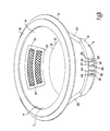
- Fig. 3 is a front perspective exploded view of the cabinet of Fig. 1,
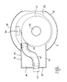
- Fig. 4 is a cross sectional side view of portion of the cabinet of Fig. 1,
- Fig. 5 is a cross sectional rear view of portion of the cabinet on the line V-V of Fig. 4,
- Fig. 6 is a sectional plan view of portion of the cabinet on the line VI-VI of Fig. 4,
- Fig. 7 is an exploded perspective view of a detail of the cabinet of Fig. 1,
- Fig. 8 is a perspective view of another detail of the cabinet of Fig. 1,
- Fig. 9 is a circuit diagram of a control circuit of the cabinet of Fig. 1,
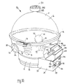
- Fig. 10 is a rear perspective view of a cabinet according to another embodiment of the invention, and
- Fig. 11 is a sectional side view of a detail of the cabinet of Fig. 11.
- Referring to the drawings, and initially to Figs. 1 to 9, there is illustrated a safety cabinet according to the invention indicated generally by the
reference numeral 1 within which experiments may be safely undertaken. Thecabinet 1 is of size and shape to be portable. Thecabinet 1 comprises a housing which comprises amain housing 4 and asupport housing 5 on which themain housing 4 is supported. - The
main housing 4 is of transparent plastics material and is formed in two parts, namely, anupper shell 6 and alower shell 7 which are releasably joined at 8. Theupper shell 6 is of hemispherical shape having an outwardly extending flange 9 extending around theperiphery 10 thereof. Thelower shell 7 is of partly hemispherical shape having aflat base 12. An outwardly extendingflange 15 extends circumferentially around thelower shell 7 for engaging the flange 9 of theupper shell 6 for securing the upper andlower shells hoop 16 of U-shape cross section extends round theflanges 9 and 15 for engaging and retaining theflanges 9 and 15 secured together. Atoggle clip 17 in thehoop 16 secures thehoop 16 to theflanges 9 and 15. Agasket 19 extending around theflange 15 sealably engages the flange 9 of theupper shell 6. The upper andlower shells interior working chamber 18 of partly spherical shape within which a negative pressure is created relative to atmosphere, as will be described below, and within which tests and experiments may be undertaken. Abase plate 21 of translucent material rests on theflat base 12 of thelower shell 7 and forms awork surface 22 on which tests, experiments and the like may be carried out. Access means comprising a pair ofhand access openings 23 are provided towards the front of thecabinet 1 in thelower shell 7 for accommodating a hand or the like into the workingchamber 18 to facilitate handling of the materials being tested during a test.Cowls 25 havingbores 28 extending therethrough for accommodating the hand or the like of an individual extend around the periphery of theopenings 23. Eachcowl 25 sealably engages thelower shell 7 around the periphery of the opening 23. First port means communicating with theworking chamber 18 comprises an outlet opening 24 in thelower shell 7 for providing the negative pressure in theworking chamber 18, as will be described below. A permeable sheet ofgauze 26 extends over theopening 24, and is secured in position over theopening 24 by aframe 27 bonded to the interior of thelower shell 7 adjacent the outlet opening 24. - Returning now to the
support housing 5, thesupport housing 5 is of injection moulded opaque plastics material and defines a hollowinterior region 29. Thesupport housing 5 comprises abase 30 and an upstanding partlycircular side wall 32 extending upwardly from thebase 30. Asupport rim 33 extends inwardly from theside wall 32 for supporting theflat base 12 of thelower shell 7 of themain housing 4. Screws (not shown) secure theflat base 12 to thesupport rim 33. -
Support members 34 extending downwardly from the base 30 support thecabinet 1 on a work bench or the like. A sub-housing 35 extends rearwardly from thesupport housing 5 at the rear thereof, and comprises a base 36 extending from thebase 30, and a pair ofside walls 37 extending upwardly from thebase 36 and from theside wall 32. Anend wall 39 extends from the base 36 between theside walls 37. Atop wall 40 extends outwardly from theside wall 32 between theside walls 37 of the sub-housing 35. - A
filter housing 44 extends from the sub-housing 35 to thelower shell 7 and communicates with the outlet opening 24 as will be described below. Thefilter housing 44 comprisesside walls 45 joined by front andrear end walls top wall 48. Anopening 49 in thetop wall 40 of the sub-housing 35 communicates thefilter housing 44 with theinterior region 29 of the sub-housing 35, as will be described below. - Second port means comprising an
exhaust outlet 50 is mounted in and extends rearwardly through theend wall 39 of the sub-housing 35. Air transfer means for withdrawing air from the workingchamber 18 to create a negative pressure in the workingchamber 18 relative to atmosphere comprises afan 51 which is mounted in theinterior region 29 of thesupport housing 5 on thebase 30. Thefan 51 is a tangential centrifugal fan. Communicating means communicates the outlet opening 24 in thelower shell 7 with theexhaust outlet 50 through thefan 51 for withdrawing air from the workingchamber 18. The communicating means comprises aduct 54 extending from aninlet 55 into thefan 51 through theinterior region 29 of thesupport housing 5 and into the sub-housing 35. Aduct 56 through thefilter housing 44 communicates theduct 54 with the outlet opening 24 in thelower shell 7 through theopening 49 in thetop wall 40 of the sub-housing 35. Aflexible conduit 58 in theinterior region 29 of thesub-housing 5 connects anoutlet 59 from thefan 51 to theexhaust outlet 50. Theduct 54 is formed between atop wall 57 of thesupport housing 5 and thetop wall 40 of the sub-housing 35 and an intermediate wall 60 extending through thesupport housing 5 and the sub-housing 35.Side walls 61 in thesupport housing 5 and theside walls 37 of the sub-housing 35 define the sides of theduct 54. The ends of theduct 54 are closed by anend wall 62 in thesupport housing 5 and theend wall 39 of the sub-housing 35. Anopening 52 in the intermediate wall 60 communicates theduct 54 with theinlet 55 to thefan 51. Theduct 56 is formed by theside walls 45, the front andrear walls top wall 48 of thefilter housing 44. When thelower shell 7 is secured in thesupport rim 33 of thesupport housing 5, thefilter housing 44 sealably engages thelower shell 7 around theoutlet opening 24. An electricallypowered motor 53 mounted on the base 30 in theinterior region 29 of thesupport housing 5 drives thefan 51 through a drive transmission (not shown). Such drive transmissions will be well known to those skilled in the art. The fan and motor are sized to give a fan capacity of twenty cubic meters per hour against a static pressure of 400 pascals. In this embodiment of the invention, when the fan is operated against a back pressure of the order of 130 to 150 pascals, the fan draws approximately sixty-eight cubic meters per hour from the workingchamber 18. - Main filter means for filtering the air as it is withdrawn from the working
chamber 18 comprises amain filter 63 releasably mounted in theduct 56 in thefilter housing 44. Themain filter 63 extends transversely of theduct 56 so that all air passing through theduct 56 passes through themain filter 63.Guide rails 64 on theside walls 45 of thefilter housing 44 guide and retain themain filter 63 in position in theduct 56. Anopening 65 in thetop wall 48 of thefilter housing 44 provides access to theduct 56 for removing and replacing themain filter 63.Lips 66 extending round theopening 65 sealably engage aclosure member 67 for closing theopening 65. Toggle clips 68 on theside walls 45 engagelugs 69 on theclosure member 67 for securing theclosure member 67 against thelips 66. - In this embodiment of the invention, the
main filter 63 is an activated carbon filter mounted in acartridge 70. Themain filter 63 is rated to remove particles of 0.3 microns and greater from the air with an efficiency of 99.997%. Needless to say, other filter mediums besides activated carbon may be used, for example, a treated activated carbon may be used, or the filter may be a composite filter, for example, the filter may be provided by a pleated HEPA filter constructed to British standard 5726;1979 which would also be provided with a prefilter. A combination of any of these filters may also be used. - A light 71 is mounted in the
interior region 29 of thesupport housing 5 beneath theflat base 12 of thelower shell 7 for illuminating the interior of the workingchamber 18. Alamp holder 72 mounted in theinterior region 29 of thesupport housing 5 engages the light 71. - A
control circuit 73 for controlling the operation of thecabinet 1 is mounted in theinterior region 29 of thesupport housing 5. Thecontrol circuit 73 is mounted in acavity 89 which is formed towards the front of thesupport housing 5. Thecontrol circuit 73 is illustrated by theblock 73 in fig. 4, and a circuit diagram of thecontrol circuit 73 is illustrated in fig. 9. Thecontrol circuit 73 comprises a microprocessor 74 which controls the operation of thecircuit 73. Thecircuit 73 is powered by a twelve volt DC supply which may be provided from AC mains or from an independent twelve volt DC supply. Asocket 75 in theend wall 39 of the sub-housing 35 receives an AC mains supply, while asocket 76 also in theend wall 39 receives a twelve volt DC supply. The AC supply is fed from thesocket 75 to atransformer 77 in thecontrol circuit 73 through amains switch 43. The mains switch 43 is mounted in theend wall 39 of the sub-housing 35. Thetransformer 77 steps the AC mains voltage down to twelve volts and delivers a twelve volt DC supply. Aselector switch 80 is provided in thecontrol circuit 73 and selects between the AC mains supply and the independent twelve volt DC supply as is described below. Power is delivered from the power source selected by theselector switch 80 to a switch modepower supply unit 81. Such power supply units will be well known to those skilled in the art. Amain control switch 78 switches on and off thecontrol circuit 73 through thepower supply unit 81. Themain control switch 78 is mounted on acontrol panel 79 in thewall 32 to the front of thecabinet 1.Switches control panel 79 control the operation of the light 71 and themotor 53 for powering thefan 51, respectively, through thepower supply unit 81 and the micro-processor 74.Light emitting diodes 84 on thecontrol panel 79 indicate the status of theswitches selector switch 80 switches from thetransformer 77 to thesocket 76 in the event of power failure to thetransformer 77. Accordingly, should power being delivered into thesocket 75 fail, if a DC supply is connected to thesocket 76, this is substantially instantaneously connected to thepower supply unit 81 through theselector switch 80. - The micro-processor is programmed to maintain the
motor 83 running for a predetermined period of time after theswitch 83 has been switched off so that the workingchamber 18 is fully purged after a test has been completed and is ready for the next test. The predetermined period of time may be any suitable time period, however, it has been found that a time period of five minutes is adequate in most cases. Alight emitting diode 85 on thecontrol panel 79 indicates if the workingchamber 18 was not purged after a previous test, for example, if the mains switch 43 was switched off simultaneously with theswitch 83 or prior to the period of purging being completed. Thelight emitting diode 85 is powered when themain control switch 78 is switched on to prepare for the next test, thus indicating to an individual that purging after the previous test had not taken place or had not been completed. This thus enables an individual to run themotor 83 for purging the workingchamber 18 prior to commencing a test. - Sensor means for monitoring the condition of the
main filter 63 comprises athermistor 86 mounted in theduct 56 of thefilter housing 44 downstream of themain filter 63. Thethermistor 86 monitors the temperature of the air which is fed back to the micro-processor 74. The micro-processor 74 is programmed to determine the air velocity and air pressure of the air downstream of thefilter 63 from the signals received from thethermistor 86. The micro-processor 74 is also programmed to act as a control means for varying the speed of themotor 53 in response to a variation in velocity of the air passing through theduct 56. In this case, on the velocity of the air falling below a certain predetermined level, the micro-processor increases the speed of themotor 53 to maintain the air velocity at or just above the predetermined level. In practice, as the filter begins to collect particles, greater fan speed is required to maintain adequate air flow from the workingchamber 18. The micro-processor 74 is also programmed to activate an alerting means, in this case, abuzzer 87 and alight emitting diode 88 both mounted in thecontrol panel 79 for indicating that themain filter 63 requires replacing or cleaning. On the micro-processor 74 determining that the speed of themotor 53 has been increased to a certain predetermined speed in order to maintain the predetermined air flow from the workingchamber 18, thebuzzer 87 andlight emitting diode 88 are activated to indicate that thefilter 63 requires replacement or cleaning. - The
exhaust outlet 50 is adapted for connecting to a central extraction network in a building for extracting air delivered through theexhaust outlet 50 and for delivering the air externally of the building or into suitable scrubbing apparatus or the like. However, in general, it is envisaged that themain filter 63 will clean the air sufficiently prior to delivery through theexhaust outlet 50 to avoid the need for connecting theexhaust outlet 50 to a central extraction network. In general, it is envisaged that thecabinet 1 will be used with theexhaust outlet 50 delivering the air withdrawn from the workingchamber 18 directly into the room. In fact, an advantage of providing theexhaust outlet 50 to the rear of thecabinet 1 is that any unpleasant fumes which may be delivered through theexhaust outlet 50 are directed away from the individual carrying out the tests or experiments. Further, it is envisaged that theexhaust outlet 50 may be connected to a conduit or duct which would deliver the exhaust air from theexhaust outlet 50 through a window or other opening from a room in which thecabinet 1 is being used. - The
fan 51 andmotor 53 are sized to provide an air velocity of 0.7 meters per second away from the operator through theaccess openings 23. Although, needless to say, it will be appreciated that air velocities greater or less than 0.7 meters per second may be provided. - In use, the material to be tested or experimented on is placed on the
base plate 21 either through thehand access openings 23 or by removing theupper shell 6 from thelower shell 7. The upper andlower shells hoop 16. With thecabinet 1 connected to a mains supply through thesocket 75, theswitches switch 83 is switched on to activate thefan 51 for creating the negative pressure environment in the workingchamber 18. If it is desired, the light 71 is switched on by thelight switch 82. Thefan 51 remains on during the period of the test or experiment, thereby continuously providing the negative pressure environment in the workingchamber 18. While thefan 51 is operational, air is withdrawn from the workingchamber 18 and made up through theaccess openings 23, thereby maintaining the negative pressure environment in the workingchamber 18. On completion of the test, thefan 51 is switched off using theswitch 83 and the material being tested may then be removed from the workingchamber 18. The micro-processor 74 keeps themotor 53 running for a predetermined period of time for operating thefan 51 to purge the workingchamber 18, so that the workingchamber 18 will then be ready for the next test. If desired, during the tests theexhaust outlet 50 may be connected to a central fume extraction network. - Should the
thermistor 86 detect a drop in velocity of air below a predetermined level in theduct 56, the micro-processor 74 speeds up themotor 53 to maintain the air speed at or above the predetermined velocity. Should the motor speed be increased to a certain predetermined speed, indicating that themain filter 63 requires cleaning or replacement, the micro-processor 74 activates thelight emitting diode 88 and thebuzzer 87, thereby indicating to an individual using thecabinet 1 the status of themain filter 63. On themain filter 63 requiring replacement, themain filter 63 is removed by removing theclosure member 67 from theopening 65. Anew filter 63 is then replaced in theduct 56 and theclosure member 67 secured in theopening 65. - In the event of a power failure of the mains power supply to the
socket 75, theselector switch 80 connects thepower supply unit 81 directly to thesocket 76. Accordingly, where a DC supply is connected to thesocket 76, the cabinet continues operating even in the event of a power supply failure. - Referring now to Figs. 10 and 11, there is illustrated a portable safety cabinet according to another embodiment of the invention indicated generally by the reference numeral 90. The cabinet 90 is substantially similar to the
cabinet 1 and similar components are identified by the same reference numeral. The main difference in this cabinet 90 and thecabinet 1 is that sleeves 91 sealably engage thecowls 25 around thehand access openings 23 and extend into the workingchamber 18. The sleeves 91 terminate ingloves 92, thereby isolating the workingchamber 18 from atmosphere through theopenings 23. An individual wishing to handle or manipulate materials in the workingchamber 18 inserts their hands into thegloves 92 and thereby direct contact with the material being tested is avoided. A third port means comprising aninlet 93 is provided adjacent the top of theupper shell 6 to permit air to be drawn into the workingchamber 18. Asecondary filter 94 is provided in acap 95 which releasably and sealably engages theinlet 93 for filtering air being drawn in through theinlet 93. In this embodiment of the invention, thesecondary filter 94 is a replaceable cartridge filter and is rated to remove particles of 0.3 microns and greater from the air with an efficiency of 99.997%. The filter in this case is a pleated HEPA filter to British standards 5726;1979.Perforations 96 are provided in thecap 95 to permit air to be drawn therethrough. - Operation of the cabinet 90 is substantially identical to the operation of the
cabinet 1 with the exception that an individual carrying out tests wishing to handle or manipulate the material in the workingchamber 18 does so through thegloves 92. - The advantage of the cabinet 90 according to this embodiment of the invention is that as well as protecting the environment from fumes, vapours or the like from the article or material under test, the individual carrying out the test is also protected by virtue of the fact that the entire working chamber is substantially totally sealed relative to the individual carrying out the test. A further and particularly important advantage of the cabinet 90 is that the environment within the working
chamber 18 of the cabinet is a clean air environment by virtue of the fact that air drawn through theinlet 93 is filtered as it is drawn into the workingchamber 18. - To facilitate portability of the
cabinets 1 and 90 described with reference to Figs. 1 to 11, the diameter of thesupport housing 5 of each cabinet is 450 millimetres, while the maximum diameter of themain housing 4 is 540 millimetres. The overall height of the cabinets from thebase member 30 of thesupport housing 5 to the top of theupper shell 6 of themain housing 4 is 550 millimetres, while the height of thesupport housing 5 is 120 millimetres. - While the cabinets described with reference to the various embodiments of the invention have been described as comprising a main housing and a support housing, the cabinets may be provided with any other suitable type of housing. Needless to say, while it is preferable, it is not essential that the main housing be of substantially spherical shape, any other shape of main housing may be provided. Furthermore, it will be appreciated that it is not essential that the entire main housing be of transparent material. The main housing may be provided with windows of transparent material or the like. Further, the main housing may be of any other material. Needless to say, the support housing may be of any other suitable material and shape.
- It will of course be appreciated that any other communicating means communicating the first and second port means may be provided and it will of course be appreciated that the fan may be mounted in any desired location in the communicating means. Needless to say, the main filter may be mounted upstream or downstream of the fan. The advantage of mounting the main filter upstream of the fan is that it cleans the air before it reaches the fan.
- Furthermore, while it is preferable, it is not essential that the main filter be replaceable. Needless to say, other suitable types of main filter may be used besides those described. Further, the secondary filter may be provided by other suitable types of filter besides that described. Indeed, in certain cases, it is envisaged that the cabinet 90 may be provided without the secondary filter. Furthermore, the inlet may be provided at any other suitable location.
- While the cabinets have been described for carrying out tests or experiments, the cabinets may be used for many other purposes. Such uses will be well known to those skilled in the art.
- It will of course be appreciated that the sensor means for monitoring air flow through the communicating means may be dispensed with, and where a sensor means is provided, any other suitable sensor means may be provided besides a thermistor. For example, in certain cases, a pressure sensor may be provided.
- While the
upper shell 6 andlower shell 7 have been described as being secured together by a hoop of U-shaped cross section, it is envisaged that the upper shell may be hingedly connected to the lower shell. - It is also envisaged that a filter may be provided on the
exhaust outlet 50. Such a filter may be to the specification of the main filter or to a different specification. - It is also envisaged that an ultra-violet light may be provided in the working chamber for providing a sterile environment in the working chamber.
- It is also envisaged that an inert gas supply, or indeed, any other desired gas supply may be connected to either the inlet to the working chamber of the cabinet 90 or to the access openings of the
cabinet 1 or 90 to provide a gas other than air in the working chamber. - A further advantage of the safety cabinets according to the invention is that where they are used in a clean room, the air being returned to the clean room through the exhaust outlet is also clean. For example, if any of the cabinets are used in a clean room with class 100 air therein, the cabinets according to the invention also return exhaust air through the outlet to a standard of class 100. The main filters in both cases are selected to provide class 100 air to be delivered through the exhaust outlet. However, it will be appreciated that it is not essential that the air being delivered through the exhaust outlet should be to class 100 standard. Furthermore, the secondary filter may be sized to provide class 100 air in the working chamber of the cabinet 90.
- It will of course be appreciated that while the microprocessor increases the speed of the motor in response to a drop in velocity of air passing through the communicating means, the micro-processor may also reduce the speed of the motor in response to an increase in velocity of air passing through the communicating means.
Claims (10)
- A safety cabinet (1) of the type comprising a housing (4,5) defining a working chamber (18) within which a negative pressure is created relative to atmosphere, characterised in that the housing (4,5) is portable, and the housing defines a substantially enclosed working chamber (18) and is constructed at least partly of transparent material for facilitating visual inspection of the working chamber (18), and the cabinet (1) comprises first port means (24) communicating with the working chamber (18), second port means (50) communicating with atmosphere, communicating means (54,56,58) communicating the first port means (24) and the second port means (50), air transfer means (51) being provided in the communicating means (54,56,58) for withdrawing air from the working chamber (18) and delivering the air through the second port means (50) for creating the negative pressure in the working chamber (18), main filter means (63) being provided in the communicating means (54,56,58) for filtering air passing through the communicating means (54,56,58), and access means (23) being provided in the housing (4,5) to the working chamber (18) for accommodating a hand or the like.
- A safety cabinet as claimed in Claim 1 characterised in that the main filter means (63) is mounted in the communicating means (54,56,58) intermediate the air transfer means (51) and the first port means (24).
- A safety cabinet as claimed in Claim 1 or 2 characterised in that the main filter means (63) is a filter provided to British standard 5726:1978.
- A safety cabinet as claimed in any preceding claim characterised in that the communicating means (54,56,58) comprises a duct (54,56) extending between the air transfer means (51) and the first port means (24), the main filter means (63) being releasably mounted in the duct (54,56), an opening (65) being provided to the duct (54,56) for replacing the main filter means (63), and a closure member (67) releasably and sealably closing the said opening (65) in the duct (54,56).
- A safety cabinet as claimed in any preceding claim characterised in that a sensor means (86) is provided in the communicating means (54,56,58) for monitoring air flow through the communicating means (54,56,58) for determining the condition of the main filter means (63), and alerting means (87,88) are provided for indicating that the main filter means (63) requires replacement, the alerting means (87,88) being responsive to the sensor means (86).
- A safety cabinet as claimed in any preceding claim characterised in that the air transfer means (51) comprises a fan (51), the fan (51) being driven by an electric motor (53).
- A safety cabinet as claimed in Claim 6 characterised in that a control means (73,74) for controlling the electric motor (53) is provided, the control means (73,74) being responsive to the sensor means (86) for varying the speed of the motor (53) in response to a variation in air velocity passing through the communicating means (54,56,58).
- A safety cabinet as claimed in any preceding claim characterised in that the access means (23) comprises an access opening (23) formed in the housing (4,5) to the working chamber (18), and a sleeve (91) extends from the access opening (23) into the working chamber (18) and sealably closes the access opening (23), the sleeve (91) terminating in a glove (92).
- A safety cabinet as claimed in any preceding claim characterised in that the housing (4,5) comprises third port means (93), the third port means (93) communicating with the working chamber, and a secondary filter means (94) being provided in the third port means (93).
- A safety cabinet as claimed in any preceding claim characterised in that the housing (4,5) comprises a main housing (4), and a support housing (5) supporting the main housing (4), the main housing (4) forming the working chamber (18) and being of substantially spherical shape, the support housing (5) housing the air transfer means (51) and the main filter means (63).
Applications Claiming Priority (6)
| Application Number | Priority Date | Filing Date | Title |
|---|---|---|---|
| IE164490A IE901644L (en) | 1990-05-07 | 1990-05-07 | Guanidines |
| IE116490 | 1990-05-07 | ||
| IE164490 | 1990-05-07 | ||
| IE116490A IE901164A1 (en) | 1990-05-07 | 1990-05-07 | A portable safety cabinet |
| IE335890 | 1990-09-17 | ||
| IE335890 | 1990-09-17 |
Publications (1)
| Publication Number | Publication Date |
|---|---|
| EP0456420A1 true EP0456420A1 (en) | 1991-11-13 |
Family
ID=27270358
Family Applications (1)
| Application Number | Title | Priority Date | Filing Date |
|---|---|---|---|
| EP91303996A Withdrawn EP0456420A1 (en) | 1990-05-07 | 1991-05-02 | A safety cabinet |
Country Status (2)
| Country | Link |
|---|---|
| EP (1) | EP0456420A1 (en) |
| GB (1) | GB2243800A (en) |
Cited By (8)
| Publication number | Priority date | Publication date | Assignee | Title |
|---|---|---|---|---|
| EP0623061A1 (en) * | 1992-11-20 | 1994-11-09 | Systems Chemistry, Inc. | Chemical vessel environmental chamber |
| EP1375115A1 (en) * | 2002-06-24 | 2004-01-02 | 3D Systems, Inc. | Ventilation and cooling in selective deposition modeling |
| GB2468657A (en) * | 2009-03-17 | 2010-09-22 | A1 Envirosciences Ltd | Laboratory Containment Apparatus |
| WO2011030161A1 (en) * | 2009-09-14 | 2011-03-17 | Nuclear Decommissioning Authority | Lighting apparatus and method of lighting |
| GB2492179A (en) * | 2011-06-23 | 2012-12-26 | Nano Second Technology Co Ltd | A housing of a wrist exercising device |
| EP2767338A3 (en) * | 2013-02-19 | 2016-01-06 | Don Whitley Scientific Limited | Controlled atmosphere workstation |
| CN113786679A (en) * | 2021-09-23 | 2021-12-14 | 上海飞域实验室设备有限公司 | Novel cover is weighed to net gas balance of negative pressure |
| CN117967987A (en) * | 2024-03-29 | 2024-05-03 | 安徽壹月科技有限公司 | Control type gas holder for multi-gas mixed conveying |
Families Citing this family (2)
| Publication number | Priority date | Publication date | Assignee | Title |
|---|---|---|---|---|
| GB9414641D0 (en) * | 1994-07-20 | 1994-09-07 | Extract Technology Ltd | Isolator system |
| ES1223000Y (en) * | 2018-11-08 | 2019-04-09 | Hospifar Sl | DEVICE FOR HANDLING HAZARDOUS MEDICINES |
Citations (9)
| Publication number | Priority date | Publication date | Assignee | Title |
|---|---|---|---|---|
| FR1147608A (en) * | 1956-04-09 | 1957-11-27 | Portable laboratory in a controlled atmosphere, known as a glove box | |
| US3134637A (en) * | 1961-11-20 | 1964-05-26 | Bashlow Archie | Dust-proof cabinet |
| US3267830A (en) * | 1964-06-22 | 1966-08-23 | William H Van Gaasbeek | Dry box apparatus |
| US3402530A (en) * | 1962-08-21 | 1968-09-24 | Israel State | Air filter installations |
| US3410619A (en) * | 1967-05-02 | 1968-11-12 | Atomic Energy Commission Usa | Fluorocarbon-lined glovebox |
| US3536370A (en) * | 1966-12-16 | 1970-10-27 | Nat Res Dev | Controlled environment apparatus |
| FR2293288A1 (en) * | 1974-12-06 | 1976-07-02 | Jean Francis Cadrot | Rotary sterile sealed cell with penetrating handling gauntlets - for manufacture of micro-electronics permits compact serialising of operations |
| FR2490990A1 (en) * | 1980-09-26 | 1982-04-02 | Frantz Jean Pierre | Transparent protective bubble for machine tool operations - is attached to peg on work table and has hand holes and sump connected vacuum feed |
| US4530272A (en) * | 1984-01-13 | 1985-07-23 | International Business Machines Corporation | Method for controlling contamination in a clean room |
Family Cites Families (11)
| Publication number | Priority date | Publication date | Assignee | Title |
|---|---|---|---|---|
| JPS4955560A (en) * | 1972-10-02 | 1974-05-29 | ||
| US4156146A (en) * | 1976-06-07 | 1979-05-22 | Hitachi Cable, Ltd. | Arrangement for replacably mounting operating member on a radiation shielding box |
| US4108509A (en) * | 1977-03-18 | 1978-08-22 | Futurecraft Corporation | Controlled environment work enclosure |
| GB1599184A (en) * | 1978-04-24 | 1981-09-30 | Wilson J | Ventilating apparatus comprising a cabinet to be ventilated |
| GB1593597A (en) * | 1978-05-23 | 1981-07-22 | Howarth Air Eng Ltd | Work cabinet |
| JPS562600A (en) * | 1979-06-21 | 1981-01-12 | Hitachi Cable | Exchanging port structure of operation member in shielding box |
| GB2058649B (en) * | 1979-09-21 | 1983-03-30 | Allwright C G | Workbenches |
| US4584930A (en) * | 1982-04-06 | 1986-04-29 | British Nuclear Fuels Limited | Ventilation systems for glove boxes |
| NL8203523A (en) * | 1982-09-10 | 1984-04-02 | Clean Air Supplies Woerden B V | WORKBENCH WITH LAMINARY AIRFLOW AS SECURITY. |
| GB8317266D0 (en) * | 1983-06-24 | 1983-07-27 | Hodge Clemco Ltd | Closed cabinets |
| US4765352A (en) * | 1987-07-17 | 1988-08-23 | Strieter Jerome F | Portable isolation enclosure for use in cleaning contaminated environments |
-
1991
- 1991-05-02 EP EP91303996A patent/EP0456420A1/en not_active Withdrawn
- 1991-05-02 GB GB9109541A patent/GB2243800A/en not_active Withdrawn
Patent Citations (9)
| Publication number | Priority date | Publication date | Assignee | Title |
|---|---|---|---|---|
| FR1147608A (en) * | 1956-04-09 | 1957-11-27 | Portable laboratory in a controlled atmosphere, known as a glove box | |
| US3134637A (en) * | 1961-11-20 | 1964-05-26 | Bashlow Archie | Dust-proof cabinet |
| US3402530A (en) * | 1962-08-21 | 1968-09-24 | Israel State | Air filter installations |
| US3267830A (en) * | 1964-06-22 | 1966-08-23 | William H Van Gaasbeek | Dry box apparatus |
| US3536370A (en) * | 1966-12-16 | 1970-10-27 | Nat Res Dev | Controlled environment apparatus |
| US3410619A (en) * | 1967-05-02 | 1968-11-12 | Atomic Energy Commission Usa | Fluorocarbon-lined glovebox |
| FR2293288A1 (en) * | 1974-12-06 | 1976-07-02 | Jean Francis Cadrot | Rotary sterile sealed cell with penetrating handling gauntlets - for manufacture of micro-electronics permits compact serialising of operations |
| FR2490990A1 (en) * | 1980-09-26 | 1982-04-02 | Frantz Jean Pierre | Transparent protective bubble for machine tool operations - is attached to peg on work table and has hand holes and sump connected vacuum feed |
| US4530272A (en) * | 1984-01-13 | 1985-07-23 | International Business Machines Corporation | Method for controlling contamination in a clean room |
Cited By (10)
| Publication number | Priority date | Publication date | Assignee | Title |
|---|---|---|---|---|
| EP0623061A1 (en) * | 1992-11-20 | 1994-11-09 | Systems Chemistry, Inc. | Chemical vessel environmental chamber |
| EP0623061A4 (en) * | 1992-11-20 | 1995-05-24 | Systems Chemistry Inc | Chemical vessel environmental chamber. |
| EP1375115A1 (en) * | 2002-06-24 | 2004-01-02 | 3D Systems, Inc. | Ventilation and cooling in selective deposition modeling |
| GB2468657A (en) * | 2009-03-17 | 2010-09-22 | A1 Envirosciences Ltd | Laboratory Containment Apparatus |
| WO2011030161A1 (en) * | 2009-09-14 | 2011-03-17 | Nuclear Decommissioning Authority | Lighting apparatus and method of lighting |
| GB2492179A (en) * | 2011-06-23 | 2012-12-26 | Nano Second Technology Co Ltd | A housing of a wrist exercising device |
| GB2492179B (en) * | 2011-06-23 | 2014-06-18 | Nano Second Technology Co Ltd | Wrist exercising device and housing thereof |
| EP2767338A3 (en) * | 2013-02-19 | 2016-01-06 | Don Whitley Scientific Limited | Controlled atmosphere workstation |
| CN113786679A (en) * | 2021-09-23 | 2021-12-14 | 上海飞域实验室设备有限公司 | Novel cover is weighed to net gas balance of negative pressure |
| CN117967987A (en) * | 2024-03-29 | 2024-05-03 | 安徽壹月科技有限公司 | Control type gas holder for multi-gas mixed conveying |
Also Published As
| Publication number | Publication date |
|---|---|
| GB9109541D0 (en) | 1991-06-26 |
| GB2243800A (en) | 1991-11-13 |
Similar Documents
| Publication | Publication Date | Title |
|---|---|---|
| US4059903A (en) | Controlled environment work enclosure | |
| EP0456420A1 (en) | A safety cabinet | |
| CA1083642A (en) | Controlled environment work enclosure | |
| US5302123A (en) | Dental handpiece lubrication purging apparatus | |
| US4787922A (en) | Filter apparatus | |
| JP2004510118A (en) | air purifier | |
| US5098506A (en) | Method and apparatus for removing floor tile mastic | |
| US20090205498A1 (en) | Air cleaner | |
| KR20190023212A (en) | Air purifier | |
| US5655253A (en) | Bench top dust collector | |
| US20220134395A1 (en) | Device for purifying air in the workspace of a nail artist | |
| US4624690A (en) | Apparatus for removing particulates | |
| CN111315484A (en) | Safety cabinet | |
| EP0614569B1 (en) | Decontamination apparatus | |
| JP2005296889A (en) | Isolator | |
| US4813984A (en) | Self-contained air monitoring unit with agitated air capability | |
| IE901164A1 (en) | A portable safety cabinet | |
| US4221081A (en) | Dust collector system for belt sander | |
| US3930818A (en) | Air cleaner | |
| WO2022095299A1 (en) | Cleaning machine | |
| GB2286665A (en) | Dust extraction arrangement | |
| US4213755A (en) | Mercury vapor purifier enclosure | |
| KR20100042311A (en) | Dry type air shower apparatus having cartridge filter | |
| GB2233441A (en) | A clean air cabinet | |
| CN219003969U (en) | Spare part clarification plant |
Legal Events
| Date | Code | Title | Description |
|---|---|---|---|
| PUAI | Public reference made under article 153(3) epc to a published international application that has entered the european phase |
Free format text: ORIGINAL CODE: 0009012 |
|
| AK | Designated contracting states |
Kind code of ref document: A1 Designated state(s): AT BE CH DE DK ES FR GB GR IT LI LU NL SE |
|
| 17P | Request for examination filed |
Effective date: 19920511 |
|
| STAA | Information on the status of an ep patent application or granted ep patent |
Free format text: STATUS: THE APPLICATION IS DEEMED TO BE WITHDRAWN |
|
| 18D | Application deemed to be withdrawn |
Effective date: 19931201 |