EP2765484B1 - Simulierte Berührungseingabe - Google Patents
Simulierte Berührungseingabe Download PDFInfo
- Publication number
- EP2765484B1 EP2765484B1 EP14154505.3A EP14154505A EP2765484B1 EP 2765484 B1 EP2765484 B1 EP 2765484B1 EP 14154505 A EP14154505 A EP 14154505A EP 2765484 B1 EP2765484 B1 EP 2765484B1
- Authority
- EP
- European Patent Office
- Prior art keywords
- pointing device
- time
- axis
- touch input
- spatial position
- Prior art date
- Legal status (The legal status is an assumption and is not a legal conclusion. Google has not performed a legal analysis and makes no representation as to the accuracy of the status listed.)
- Active
Links
Images




Classifications
-
- G—PHYSICS
- G06—COMPUTING OR CALCULATING; COUNTING
- G06F—ELECTRIC DIGITAL DATA PROCESSING
- G06F3/00—Input arrangements for transferring data to be processed into a form capable of being handled by the computer; Output arrangements for transferring data from processing unit to output unit, e.g. interface arrangements
- G06F3/01—Input arrangements or combined input and output arrangements for interaction between user and computer
- G06F3/017—Gesture based interaction, e.g. based on a set of recognized hand gestures
-
- G—PHYSICS
- G06—COMPUTING OR CALCULATING; COUNTING
- G06F—ELECTRIC DIGITAL DATA PROCESSING
- G06F3/00—Input arrangements for transferring data to be processed into a form capable of being handled by the computer; Output arrangements for transferring data from processing unit to output unit, e.g. interface arrangements
- G06F3/01—Input arrangements or combined input and output arrangements for interaction between user and computer
- G06F3/03—Arrangements for converting the position or the displacement of a member into a coded form
- G06F3/033—Pointing devices displaced or positioned by the user, e.g. mice, trackballs, pens or joysticks; Accessories therefor
- G06F3/0346—Pointing devices displaced or positioned by the user, e.g. mice, trackballs, pens or joysticks; Accessories therefor with detection of the device orientation or free movement in a three-dimensional [3D] space, e.g. 3D mice, 6-DOF [six degrees of freedom] pointers using gyroscopes, accelerometers or tilt-sensors
-
- G—PHYSICS
- G06—COMPUTING OR CALCULATING; COUNTING
- G06F—ELECTRIC DIGITAL DATA PROCESSING
- G06F3/00—Input arrangements for transferring data to be processed into a form capable of being handled by the computer; Output arrangements for transferring data from processing unit to output unit, e.g. interface arrangements
- G06F3/01—Input arrangements or combined input and output arrangements for interaction between user and computer
- G06F3/03—Arrangements for converting the position or the displacement of a member into a coded form
- G06F3/033—Pointing devices displaced or positioned by the user, e.g. mice, trackballs, pens or joysticks; Accessories therefor
- G06F3/038—Control and interface arrangements therefor, e.g. drivers or device-embedded control circuitry
-
- G—PHYSICS
- G06—COMPUTING OR CALCULATING; COUNTING
- G06F—ELECTRIC DIGITAL DATA PROCESSING
- G06F3/00—Input arrangements for transferring data to be processed into a form capable of being handled by the computer; Output arrangements for transferring data from processing unit to output unit, e.g. interface arrangements
- G06F3/01—Input arrangements or combined input and output arrangements for interaction between user and computer
- G06F3/048—Interaction techniques based on graphical user interfaces [GUI]
- G06F3/0481—Interaction techniques based on graphical user interfaces [GUI] based on specific properties of the displayed interaction object or a metaphor-based environment, e.g. interaction with desktop elements like windows or icons, or assisted by a cursor's changing behaviour or appearance
-
- H—ELECTRICITY
- H04—ELECTRIC COMMUNICATION TECHNIQUE
- H04N—PICTORIAL COMMUNICATION, e.g. TELEVISION
- H04N21/00—Selective content distribution, e.g. interactive television or video on demand [VOD]
- H04N21/40—Client devices specifically adapted for the reception of or interaction with content, e.g. set-top-box [STB]; Operations thereof
- H04N21/41—Structure of client; Structure of client peripherals
- H04N21/422—Input-only peripherals, i.e. input devices connected to specially adapted client devices, e.g. global positioning system [GPS]
- H04N21/42204—User interfaces specially adapted for controlling a client device through a remote control device; Remote control devices therefor
- H04N21/42206—User interfaces specially adapted for controlling a client device through a remote control device; Remote control devices therefor characterized by hardware details
- H04N21/42222—Additional components integrated in the remote control device, e.g. timer, speaker, sensors for detecting position, direction or movement of the remote control, microphone or battery charging device
-
- H—ELECTRICITY
- H04—ELECTRIC COMMUNICATION TECHNIQUE
- H04N—PICTORIAL COMMUNICATION, e.g. TELEVISION
- H04N21/00—Selective content distribution, e.g. interactive television or video on demand [VOD]
- H04N21/40—Client devices specifically adapted for the reception of or interaction with content, e.g. set-top-box [STB]; Operations thereof
- H04N21/41—Structure of client; Structure of client peripherals
- H04N21/422—Input-only peripherals, i.e. input devices connected to specially adapted client devices, e.g. global positioning system [GPS]
- H04N21/42204—User interfaces specially adapted for controlling a client device through a remote control device; Remote control devices therefor
- H04N21/42206—User interfaces specially adapted for controlling a client device through a remote control device; Remote control devices therefor characterized by hardware details
- H04N21/42224—Touch pad or touch panel provided on the remote control
-
- G—PHYSICS
- G06—COMPUTING OR CALCULATING; COUNTING
- G06F—ELECTRIC DIGITAL DATA PROCESSING
- G06F2203/00—Indexing scheme relating to G06F3/00 - G06F3/048
- G06F2203/048—Indexing scheme relating to G06F3/048
- G06F2203/04806—Zoom, i.e. interaction techniques or interactors for controlling the zooming operation
-
- H—ELECTRICITY
- H04—ELECTRIC COMMUNICATION TECHNIQUE
- H04N—PICTORIAL COMMUNICATION, e.g. TELEVISION
- H04N21/00—Selective content distribution, e.g. interactive television or video on demand [VOD]
- H04N21/40—Client devices specifically adapted for the reception of or interaction with content, e.g. set-top-box [STB]; Operations thereof
- H04N21/41—Structure of client; Structure of client peripherals
- H04N21/422—Input-only peripherals, i.e. input devices connected to specially adapted client devices, e.g. global positioning system [GPS]
- H04N21/42204—User interfaces specially adapted for controlling a client device through a remote control device; Remote control devices therefor
Definitions
- Multi-touch input or gesturing may refer to the ability of an electronic device to detect and perform a specific function based on input made by two or more points of contact with a touch-sensitive surface.
- An example of a multi-touch input includes a "pinch to zoom" gesture, where two fingers may be placed on a touch surface to zoom in/out of a particular screen image (e.g., photo, web page, etc.) by a pinching/spreading motion.
- Multi-touch gesturing is however typically unavailable in scenarios where a particular device does not include or incorporate a touch sensitive surface.
- US2012/256835 discloses techniques for using a motion sensitive device as a controller.
- WO2013/104570 discloses a user to machine interface emulating a touch interface on a screen and method for operating the same.
- US2005/212756 discloses a motion controlled handheld device includes a display having a viewable surface and operable to generate a current image.
- US2012/200497 discloses an intelligent remote controlling device.
- US2012/320198 discloses a method for generating a TV input command using a remote controller having an imaging sensor.
- FIG. 1 shows an example media content distribution system 100 in which aspects of the present disclosure may be implemented.
- the system 100 is depicted in a simplified and conceptual form, and may generally include more or fewer systems, devices, networks, and/or other components as desired.
- number and type of features or elements incorporated within the system 100 may or may not be implementation specific, and at least some of the aspects of the system 100 may be similar to a cable television distribution system, or other type of media or content distribution system.
- the "television receiver” as described throughout may be any type of television receiver, such as a set-top-box for example.
- the "television receiver” may correspond to functionality integrated into a television, a digital video recorder, a tablet, or any other computing system or device, and variations thereof. Additionally, features and concepts as discussed throughout the present disclosure may be applicable to any type or form of networked computing system environment, and may not be limited to a satellite television system implementation, a cable television system implementation, or other particular implementation.
- the example system 100 includes a service provider 102, a satellite uplink 104, a plurality of orbiting (e.g., geosynchronous) satellites 106(a-c), a satellite dish 108, a television receiver 110, a television 112, and a pointing device 114.
- the television receiver 110 at least includes an ICE (Input Control Engine) 116
- the pointing device 114 includes an input control 118 and a gyroscope 120.
- the ICE 116, together with the input control 118 and the gyroscope 120 are configured to enable a user to implement a touch or multi-touch input using the pointing device 114, without the requirement of the television 112 having a touch-sensitive surface.
- the system 100 also includes at least one network 122 that establishes a bidirectional communication path for data transfer between the television receiver 110 and the television 112.
- the network 122 may further establish a bidirectional communication path for data transfer between the television receiver 110 and the service provider 102 (not shown).
- the network 122 may incorporate or exhibit any number of terrestrial and/or non-terrestrial network features or elements.
- the network 122 may incorporate or exhibit any number of features or elements of various wireless and/or hardwired packet-based communication networks such as, for example, a WAN (Wide Area Network) network, a HAN (Home Area Network) network, a LAN (Local Area Network) network, a WLAN (Wireless Local Area Network) network, the Internet, or other any type of communication network(s) configured such that data may be transferred among respective elements of the example system 100.
- WAN Wide Area Network
- HAN Home Area Network
- LAN Local Area Network
- WLAN Wireless Local Area Network
- the Internet or other any type of communication network(s) configured such that data may be transferred among respective elements of the example system 100.
- the television receiver 110 may form at least a portion of a particular home computing network, and may each be respectively configured such as to enable communication(s) in accordance with any particular communication protocol(s) and/or standard(s) including, for example, TCP/IP (Transmission Control Protocol/Internet Protocol), DLNA/DTCP-IP (Digital Living Network Alliance/Digital Transmission Copy Protection over Internet Protocol), HDMI/HDCP (High-Definition Multimedia Interface/High-bandwidth Digital Content Protection), and others.
- TCP/IP Transmission Control Protocol/Internet Protocol
- DLNA/DTCP-IP Digital Living Network Alliance/Digital Transmission Copy Protection over Internet Protocol
- HDMI/HDCP High-Definition Multimedia Interface/High-bandwidth Digital Content Protection
- the satellites 106 are configured to receive uplink signals 124(a-b) from the satellite uplink 104.
- the uplink signals 124 may contain one or more transponder streams of particular data or content (e.g., a particular television channel) that is supplied by the service provider 102.
- each of the respective uplink signals 124 may contain various encoded HD (High Definition) television channels, various SD (Standard Definition) television channels, on-demand programming, programming information, and/or any other content in the form of at least one transponder stream and in accordance with an allotted carrier frequency and bandwidth.
- different television channels may be carried using different ones of the satellites 106.
- Different television channels may also be carried using different transponders of a particular satellite (e.g., satellite 106a); thus, such television channels may be transmitted at different frequencies and/or different frequency ranges.
- a first and second television channel may be carried on a first carrier frequency over a first transponder of satellite 106a
- a third, fourth, and fifth television channel may be carried on second carrier frequency over a first transponder of satellite 106b
- the third, fourth, and fifth television channel may be carried on a second carrier frequency over a second transponder of satellite 106a, etc.
- the satellites 106 may further be configured to relay the uplink signals 124 to the satellite dish 108 as downlink signals 126(a-b). Similar to the uplink signals 124, each of the downlink signals 126(a-b) may contain one or more transponder streams of particular data or content, such as various encoded and/or electronically scrambled television channels, on-demand programming, etc., in accordance with an allotted carrier frequency and bandwidth.
- the downlink signals 126 may not necessarily contain the same content as a corresponding one of the uplink signals 124.
- the uplink signal 124a may include a first transponder stream containing at least a first group of television channels
- the downlink signal 126a may include a second transponder stream containing at least a second, different group of television channels.
- the first and second group of television channels may have one or more television channels in common.
- the satellite dish 108 may be provided for use (e.g., on a subscription basis) to receive television channels provided by the service provider 102, satellite uplink 104, and/or satellites 106.
- the satellite dish 108 may be configured to receive particular transponder streams, or downlink signals (e.g., downlink signals 126), from the satellites 106.
- the television receiver 110 which is communicatively coupled to the satellite dish 108, may subsequently select via tuner (not shown), for example, and relay particular transponder streams to the television 112 for display thereon as desired.
- the satellite dish 108 and the television receiver 110 may, respectively, be configured to receive and relay at least one premium HD-formatted television channel to the television 112.
- the premium HD channel may be output to the television 112 from the television receiver 110 in accordance with the HDMI/HDCP content protection technologies.
- the television receiver 110 may be configured to output a plurality of interfaces to the television 112.
- the television receiver 110 may be configured to output an EPG (Electronic Programming Guide) 128 to the television 112.
- the EPG 128 may at least present various information related to television channels and the timing of programs or programming appearing on such television channels (e.g., as received from satellites 106).
- the EPG 128 may at least display channel information associated with a channel "2009,” where a "Movie M1" is listed as scheduled to appear on the channel "2009" during a particular time period "8-10 PM" of a particular day, etc.
- a user may manipulate a cursor 130 using the pointing device 114 to select (e.g., via “point and click") the "Movie M1" for viewing on the television 112.
- the television receiver 110 may further be configured to output a plurality of application icons to the television 112.
- number and type of application icons output by the television receiver 110 to the television 112 may vary, and may or may not be implementation specific.
- the television receiver 110 may be configured to output at least an Internet icon 132, a Games icon 134, a Pictures icon 136, a Maps icon 138, a Movies icon 140, and an Other icon 142.
- the Other icon 142 is intended to represent "other" types of application icons not expressly shown in FIG. 1 .
- a particular application icon when selected may open a corresponding application, or a folder containing corresponding application data, for interaction and/or viewing by a user.
- a user may manipulate the cursor 130 using the pointing device 114 to select the Maps icon 138 for immediate viewing of a particular "map" or "map-related" interface 144 on the television 112.
- the user may wish to interact with a "map" or "map-related" image as displayed on, within, or by the interface 144.
- a user may manipulate the cursor 130 using the pointing device 114 to interact with an image of the contiguous United States displayed within the interface 144.
- this interaction may entail one or more discrete "point and click” actions consistent with a "single-point" input response mode such as, for example, selection of a particular button or command to "zoom-in” to the image of the contiguous United States.
- a discrete "point and click” action may provide an "incomplete” or “lacking” user experience, because the discrete "point and click” actions may be insufficient to enable a user to experience more sophisticated interactions with the interface 144.
- the ICE 116 is configured to address these and other issues that may be encountered with interacting with features or functionality associated with any one of the respective icons 132, 134, 136, 138, 140, and 142.
- FIG. 2 shows a simulated multi-touch input in accordance with the present disclosure.
- FIG. 2 shows a simulated multi-touch "pinch to zoom" from the perspective of movement of the cursor 130 within the interface 144 of FIG. 1 .
- the "simulated" input response mode enables a user to implement a touch or multi-touch input using the pointing device 114, without the requirement of the television 112 having a touch-sensitive surface. The user thus experiences a more convenient, sophisticated, complete, and/or satisfying interaction with the interface 144.
- a simulated multi-touch "pinch to zoom” input may be considered more “fluid” and/or more “sophisticated” when compared to a "zoom” function implemented by discrete “point and click” actions.
- a user may be required to perform multiple "click” actions, interspersed with multiple “drag” actions to perfect a "zoom-in” to an intended feature.
- a user in order to "zoom-in” to a particular geographical point of interest within the interface 144 via a simulated multi-touch "pinch to zoom-in” input, a user can perform a single “click” action to engage the simulated multi-touch "pinch to zoom-in” input, and then perform a "fluid” or “continuous” movement with the pointing device 114 to perfect a "zoom-in” to an intended feature.
- Such an implementation may at least be perceived to be a less time consuming, and a more user-friendly and satisfying experience in interacting with the interface 144.
- a user may initially manipulate the cursor 130 using the pointing device 114 to identify or locate a particular geographical point of interest within the interface 144. For example, as a first step, a user manipulates the cursor 130 using the pointing device 114 to roughly identify or locate the intersection of Utah, Colorado, Arizona, and New Mexico within the contiguous United States, a unique political geographic feature commonly known as the "Four Corners" landmark. Subsequently, to initiate a simulated "pinch to zoom-in” input, the user actuates the input control 118 of the pointing device 114 (see FIG. 1 ) to engage the ICE 116 of the television receiver 110.
- the input control 118 may comprise of a depressible button incorporated within or on the pointing device 114.
- the input control 118 may be configured to support any type of HMI (Human-Machine Interaction) to engage the ICE 116 of the television receiver 110.
- HMI Human-Machine Interaction
- VIC Vehicle Input Control
- the first plot 146 illustrates a variable A that indicates initial actuation of the input control 118 of the pointing device 114 to activate the ICE 116, and a variable B that indicates secondary actuation of the input control 118 of the pointing device 114 to deactivate the ICE 116, corresponding to termination of the "zoom-in.”
- the ICE 116 simulates or emulate a multi-touch "pinch to zoom-in" input based on movement of the cursor 130 (i.e., movement of the pointing device 114), as discussed in further detail below.
- a "zoom factor” or a "magnitude” of the "zoom-in” may be proportional to a distance represented by a variable C within the interface 144. This distance may correspond to a distance that is travelled by the cursor 130 between the initial and the secondary actuation of the input control 118.
- the distance represented by the variable C may correspond to a "magnitude" of the "zoom-in” on the "Four Corners" landmark on the order of meters.
- a similar process may be performed in a simulated multi-touch "spread to zoom-out" input in accordance with the present disclosure.
- the user may move the cursor 130 across the interface 144 to a lower left portion within the interface 144 to perfect the simulated "spread to zoom-out," where an origin of the "zoom-out" is roughly identified or located at the "Four Corners" landmark.
- motion of the cursor 130 with respect to the reference axis 148 to the lower left portion, or to the upper right portion described above, within the interface 144 does not have to be precise.
- motion of the cursor 130 with respect to the reference axis 148 to the lower left portion within the interface 144 does not have to be at a predetermined angle with respect to one or more axes of the reference axis 148. Rather, the "spread to zoom-out" may be realized by general movement of the cursor 130 with respect to the reference axis 148 to the lower left portion within the interface 144, which is approximately opposite of movement of the cursor 130 across the interface 144 to emulate the "pinch to zoom-in.”
- Other simulated touch "inputs" in accordance with the present disclosure may or may not follow such reciprocal or opposite movement in implementation.
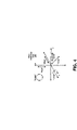
- FIG. 3 movement of the pointing device 114 of FIG. 1 to implement the simulated multi-touch input of FIG. 2 is shown mapped to a particular reference coordinated system.
- FIG. 3 illustrates a 3-dimensional reference axis 152 of the gyroscope 120 of the pointing device 114 (see FIG. 1 ), along with a time axis 154 and a displacement axis 156.
- initial actuation of the input control 118 of the pointing device 114 to activate the ICE 116 corresponds to a time t(begin) marked on the time axis 154
- secondary actuation of the input control 118 of the pointing device 114 to deactivate the ICE 116 corresponds to a time t(end) marked on the time axis 154.
- the pointing device 114 may be configured to transmit an event message to the ICE 116 of the television receiver 110.
- the periodic interval 158 may correspond to about 10 (ten) microseconds.
- a duration of the periodic interval 158 may or may not be implementation specific.
- each respective event message, corresponding to a particular "tick" on the time axis 154 includes displacement information of the pointing device 114 as measured with respect to the reference axis 152 by the gyroscope 120, along with an indication of a time corresponding to the displacement information.
- an event message transmitted at a time t2 on the time axis 154 may at least include the information [x2, y2, z2, t2], where the component x2 corresponds to a relative position of the pointing device 114 along the x-axis of the reference axis 152 at time t2, the component y2 corresponds to a relative position of the pointing device 114 along the y-axis of the reference axis 152 at time t2, and the component z2 corresponds to a relative position of the pointing device 114 along the z-axis of the reference axis 152 at time t2.
- the ICE 116 can be configured to implement and control the "zoom-in” based on information contained with event messages as received from the pointing device 114 between time t(begin) and time t(end). For example, the ICE 116 may be configured to identify, based on received event messages, displacement of the pointing device 114 from a first relative spatial position at time t(begin) to a second relative spatial position at time t(end). In this example, the second relative spatial position generally exhibits "x" and "y” components greater or more positive in magnitude than "x" and "y” components of the first relative spatial position.
- This may, for example, be correlated to a user moving the pointing device 114 from an initial "lower left” orientation, such as the pointing device 114 being held in the user's right hand near the left leg, to a final "upper right” orientation, such as the pointing device 114 being held in the right user's hand with the arm held out straight from the body at shoulder lever, in a diagonal movement.
- an initial "lower left” orientation such as the pointing device 114 being held in the user's right hand near the left leg
- a final "upper right” orientation such as the pointing device 114 being held in the right user's hand with the arm held out straight from the body at shoulder lever, in a diagonal movement.
- Such an example displacement of the pointing device 114 is shown in FIG. 3 .
- a "zoom factor” or a "magnitude” of the "zoom-in” may be proportional to a distance travelled by the pointing device 114 between the first and second relative spatial position. For example, and assuming a "z" component is approximately 0 (zero), the ICE 116 may derive relative displacement of the pointing device 114 between the first and second relative spatial position by performing a component-by-component operation of the form: [xN, yN, 0, tN] - [x1, y1, 0, t1], where N is a non-zero integer value greater than 1 (one).
- the temporal component [tN-t1] may be used in combination with the displacement component [xN-x0, yN-y0] to determine a velocity or average velocity of movement between the first and second relative spatial position.
- this velocity may be used by the ICE 116 to control a "speed" at which the "zoom-in” is performed during the "pinch to zoom-in” as emulated by the ICE 116, based on the linear relationship between distance and velocity and time.
- a "speed" at which the "zoom-in” to the "Four Corners" landmark in FIG. 2 is perceived by a user may be dependent on how fast the user moves pointing device 114 over the distance represented by the variable C.
- the time axis 154 and the displacement axis 156 may be partitioned into a first interval 160 and a second interval 162.
- the ICE 116 may calculate, based on information contained within event messages as received within the first interval 160, user intention as to a "type" of touch input to emulate.
- the ICE 116 may calculate distance and direction travelled by the pointing device 114 over the first interval 160 by performing a component-by-component operation of the form: [x3, y3, z3, t3] - [x1, y1, z1, t1].
- duration or length of the first interval 160 may be configurable, and assuming both components [x3-x1] and [y3-y1] are positive or greater than 0 (zero), and the component [z3-z1] is evaluated as approximately or about 0 (zero) within a predetermined and configurable error margin ⁇ (see reference axis 152), the ICE 116 may determine or estimate that movement of the pointing device 114 is approximately between or from the initial "lower left” orientation to the final "upper right” orientation as discussed above.
- the ICE 116 may map such a movement to the example "pinch to zoom-in” input, thus estimating or determining user intention as to a "type" of touch input to implement.
- information contained within event messages as received within the first interval 160 may be used by the ICE 116 to control the "zoom-in" of the simulated "pinch to zoom-in” in a manner as described above.
- the ICE 116 may be configured to emulate any type of touch or multi-touch input in accordance with the present disclosure.
- FIG. 4 a mapping of multiple touch or multi-touch inputs in relation to the particular reference coordinated system of FIG. 3 is shown.
- FIG. 4 shows a mapping of multiple touch or multi-touch inputs in relation to the reference axis 152 of the gyroscope 120 of FIG. 1 .
- any particular simulated touch or multi-touch input may be mapped to any individual, or any particular combination, of the x-axis and y-axis and z-axis of the reference axis 152.
- mapping may be predetermined and configurable, there is no requirement that maps a particular gesture to a particular movement.
- these and other types of inputs may be simulated or emulated in a manner similar to that described above in connection with FIGS. 1 to 3 .
- FIG. 4 shows an example "scroll" touch input mapped to the x-axis of the reference axis 152.
- the ICE 116 is configured to identify movement of the pointing device 114 in a horizontal direction, and emulate a "scroll" touch input based on information received within respective event messages during movement or displacement of the pointing device 114.
- This may, for example, be correlated to a user moving the pointing device 114 from an initial "left” position or orientation, such as the pointing device 114 being held in the user's right hand with the arm held out across the body at left shoulder level, to a final "right” position or orientation, such as the pointing device 114 being held in the user's right hand with the arm held out straight from the body at right shoulder level, in a horizontal movement.
- an initial "left” position or orientation such as the pointing device 114 being held in the user's right hand with the arm held out across the body at left shoulder level
- a final "right” position or orientation such as the pointing device 114 being held in the user's right hand with the arm held out straight from the body at right shoulder level
- FIG. 4 further shows an example "flick" touch input mapped to the y-axis of the reference axis 152.
- the ICE 116 is configured to identify movement of the pointing device 114 in a vertical direction, and emulate a "flick" touch input based on information received within respective event messages during movement or displacement of the pointing device 114. This may, for example, be correlated to a user moving the pointing device 114 from an initial "up" position or orientation, such as the pointing device 114 being held in the user's right hand with the arm held out straight at right shoulder level, to a final "down" position or orientation, such as the pointing device 114 being held in the user's right hand with the arm held out at right leg level, in a vertical movement.
- Other embodiments are possible.
- FIG. 4 further shows an example "drag" touch input mapped to the z-axis of the reference axis 152.
- the ICE 116 is configured to identify movement of the pointing device 114 in a forward or backward direction, and emulate a "drag" touch input based on information received within respective event messages during displacement of the pointing device 114.
- This may, for example, be correlated to a user moving the pointing device 114 from an initial "forward” position or orientation, such as the pointing device 114 being held in the user's right hand with the arm held out from the body at right shoulder level, to a final “backward” position or orientation, such as the pointing device 114 being held in the user's right hand near the chest at right shoulder lever, in a “backward” or “reverse” movement.
- an initial "forward” position or orientation such as the pointing device 114 being held in the user's right hand with the arm held out from the body at right shoulder level
- a final “backward” position or orientation such as the pointing device 114 being held in the user's right hand near the chest at right shoulder lever
- FIG. 4 further shows an example "other" touch input mapped to the x-axis and y-axis of the reference axis 152.
- the ICE 116 may be configured to identify movement of the pointing device 114 in an approximate diagonal direction, and emulate an "other" touch input based on information received within respective event messages during displacement of the pointing device 114.
- This may, for example, be correlated to a user moving the pointing device 114 from an initial "upper right” position or orientation, such as the pointing device 114 held in the user's right hand with the arm held out across the body at left shoulder level, to a final “lower right” position or orientation, such as the pointing device 114 being held in the user's right hand near the right leg, in a diagonal movement.
- the "other" touch input is intended to represent “other" types of touch inputs not expressly shown in FIG. 4 . Other embodiments are possible.
- FIG. 4 further shows an example "rotate” touch input mapped to the x-axis and y-axis of the reference axis 152.
- the ICE 116 may be configured to identify circular movement of the pointing device 114, and emulate a "rotate clockwise” or “rotate counter clockwise” touch input based on information received within respective event messages during displacement of the pointing device 114.
- This may, for example, be correlated to a user moving the pointing device 114 from an initial "stationary” position or orientation, such as the pointing device 114 being held in the user's right hand with the arm held out straight from the body at right shoulder level, back to the initial "stationary” position or orientation in a “circular” movement, such as by inscribing an imaginary letter “O" in space using the pointing device 114.
- an initial "stationary” position or orientation such as the pointing device 114 being held in the user's right hand with the arm held out straight from the body at right shoulder level
- FIG. 4 further shows an example "rotate" touch input mapped to the z-axis of the reference axis 152.
- the ICE 116 may be configured to identify rotational movement of the pointing device 114, and emulate a "rotate clockwise” or “rotate counter clockwise” touch input based on information received within respective event messages during displacement of the pointing device 114. This may, for example, be correlated to a user moving the pointing device 114 from an initial "stationary" position or orientation, such as the pointing device 114 being held in the user's right hand with the arm held out straight from the body at right shoulder level, to a secondary "stationary" position or orientation, such as by rotating the pointing device 114 by rotation of the wrist. Other embodiments are possible.
- the ICE 116 may track movement of the cursor 130 to determine or identify, for example, the "Four Corners" landmark as the origin of the simulated "pinch to zoom" as described above at least in connection with FIG. 2 .
- the television receiver 110 or the ICE 116 may render the cursor 130 within the interface 144 at an arbitrary initial coordinate (x, y), with reference to the reference axis 148.
- the television receiver 110 or the ICE 116 may then track periodically or at least intermittently relative displacement of the cursor 130 within the interface 144 in time.
- a "tip" of the cursor may be determined to point to, approximately and depending on resolution of the interface 144, coordinate (x1, y1).
- the "tip” of the cursor may be determined to point to coordinate (x2, y2).
- the "tip” of the cursor may be determined to point to coordinate (x3, y3).
- the "tip” of the cursor may be determined to point to coordinate (x4, y4).
- the "tip" of the cursor may be determined to point to coordinate (x5, y5).
- the ICE 116 may emulate the "pinch to zoom-out” in a manner such as described above using the coordinate (x5, y5), which may be matched to the "Four Corners" landmark within the image as displayed within the interface 144, as an origin of the "zoom-out.”
- the coordinate (x5, y5) may be matched to the "Four Corners" landmark within the image as displayed within the interface 144, as an origin of the "zoom-out."
- Other embodiments are possible.
- an example method 600 for switching a user interface input response mode is shown in accordance with the principles of the present disclosure.
- the method 600 is described as implemented by or on the television receiver 110 of FIG. 1 .
- Other embodiments are however possible.
- one or more modules or steps of the example method 600 may be implemented by one or more of the other respective devices or components within the example system 100 of FIG. 1 as described above.
- the method 600 includes receiving (module 602), by the television receiver 110 from the pointing device 114, a control signal to activate the ICE 116.
- activation of the ICE 116 may correspond to enabling the ICE 116 to simulate or emulate a touch input based on movement of the pointing device 114 in accordance with the present disclosure.
- the method may further includes determining (module 604), by the ICE 116 of the television receiver 110, a direction of motion of the pointing device 114 with reference to the reference axis 152 of the gyroscope 120 of the pointing device 114.
- the ICE 116 may derive at least a direction of motion of the pointing device 114 over the first interval 160 (see FIG. 3 ) based on an output of the gyroscope 120 over the first interval 160.
- the ICE 116 may extract information contained within event messages as received within the first interval 160, and perform a component-by-component vector-type operation of the form: [xM, yM, zM, tM] - [x1, y1, z1, t1], where M is a non-zero integer value greater than integer value 1 (one), to derive at least a direction of motion of the pointing device 114 over the first interval 160.
- the method 600 further includes associating (module 606), by the ICE 116 of the television receiver 110, the direction of motion of the pointing device 114 with a particular touch input to be simulated by the ICE 116 based on the motion of the pointing device 114.
- the ICE 116 maps the direction of motion of the pointing device 114 to one or more particular axes of the reference axis 152 of the gyroscope 120.
- the ICE 116 maps a "diagonal" direction of motion of the pointing device 114 to the x-axis and y-axis of the reference axis 152, and associate the "diagonal" direction of motion along the x-axis and y-axis with a "pinch to zoom-in” or a "pinch to zoom-out” input.
- the ICE 116 determines, based on information contained within event messages as received within the first interval 160, user intention as to a "type" of touch input to emulate.
- the method may further includes switching (module 608), by the ICE 116 of the television receiver 110, the user interface input response mode of the interface 144 from a "single-point" input response mode such as, for example, a mode responsive to one or more discrete "point and click” actions to be implemented using the pointing device 114, to a "simulated" input response mode that enables a user to implement the above-mentioned particular touch input to be simulated using the pointing device 114.
- a single-point such as, for example, a mode responsive to one or more discrete "point and click” actions to be implemented using the pointing device 114
- the method 600 may further include receiving (module 610), by the television receiver 110 from the pointing device 114, a control signal to deactivate the ICE 116.
- deactivation of the ICE 116 may correspond to disabling the ICE 116 to simulate or emulate a touch input based on movement of the pointing device 114 in accordance with the present disclosure.
- the ICE 116 in response to the disabling, may switch the user interface input response mode of the interface 144 from the "simulated" input response mode back to the "single-point" input response mode.
- Other embodiments are possible.
- An example of a computer system or device 700 includes an enterprise server, blade server, desktop computer, laptop computer, personal data assistant, smartphone, gaming console, set-top-box, and any other type machine for performing calculations.
- the computer system 700 may be wholly or at least partially incorporated as part of previously-described computing devices, such as at least the television receiver 110, the television 112, and the pointing device 114 of FIG. 1 .
- the example computer device 700 may be configured to perform and/or include instructions that, when executed, cause the computer system 700 to perform the method of FIG. 6 .
- FIG. 7 is intended only to provide a generalized illustration of various components, any or all of which may be utilized as appropriate. FIG. 7 , therefore, broadly illustrates how individual system elements may be implemented in a relatively separated or relatively more integrated manner.
- the computer device 700 is shown comprising hardware elements that can be electrically coupled via a bus 702 (or may otherwise be in communication, as appropriate).
- the hardware elements may include a processing unit with one or more processors 704, including without limitation one or more general-purpose processors and/or one or more special-purpose processors (such as digital signal processing chips, graphics acceleration processors, and/or the like); one or more input devices 706, which can include without limitation a remote control, a mouse, a keyboard, and/or the like; and one or more output devices 708, which can include without limitation a presentation device (e.g., television), a printer, and/or the like.
- a presentation device e.g., television
- the computer system 700 may further include (and/or be in communication with) one or more non-transitory storage devices 710, which can comprise, without limitation, local and/or network accessible storage, and/or can include, without limitation, a disk drive, a drive array, an optical storage device, a solid-state storage device, such as a random access memory (“RAM”), and/or a read-only memory (“ROM”), which can be programmable, flash-updateable, and/or the like.
- RAM random access memory
- ROM read-only memory
- Such storage devices may be configured to implement any appropriate data stores, including without limitation, various file systems, database structures, and/or the like.
- the computer device 700 might also include a communications subsystem 712, which can include without limitation a modem, a network card (wireless or wired), an infrared communication device, a wireless communication device, and/or a chipset (such as a Bluetooth TM device, an 802.11 device, a WiFi device, a WiMax device, cellular communication facilities (e.g., GSM, WCDMA, LTE, etc.), and/or the like.
- the communications subsystem 712 may permit data to be exchanged with a network (such as the network described below, to name one example), other computer systems, and/or any other devices described herein.
- the computer system 700 will further comprise a working memory 714, which can include a RAM or ROM device, as described above.
- the computer device 700 also can comprise software elements, shown as being currently located within the working memory 714, including an operating system 716, device drivers, executable libraries, and/or other code, such as one or more application programs 718, which may comprise computer programs provided by various embodiments, and/or may be designed to implement methods, and/or configure systems, provided by other embodiments, as described herein.
- an operating system 716 operating system 716
- device drivers executable libraries
- application programs 718 which may comprise computer programs provided by various embodiments, and/or may be designed to implement methods, and/or configure systems, provided by other embodiments, as described herein.
- code and/or instructions can be used to configure and/or adapt a general purpose computer (or other device) to perform one or more operations in accordance with the described methods.
- a set of these instructions and/or code might be stored on a non-transitory computer-readable storage medium, such as the storage device(s) 710 described above.
- the storage medium might be incorporated within a computer system, such as computer system 700.
- the storage medium might be separate from a computer system (e.g., a removable medium, such as flash memory), and/or provided in an installation package, such that the storage medium can be used to program, configure, and/or adapt a general purpose computer with the instructions/code stored thereon.
- These instructions might take the form of executable code, which is executable by the computer device 700 and/or might take the form of source and/or installable code, which, upon compilation and/or installation on the computer system 700 (e.g., using any of a variety of generally available compilers, installation programs, compression/decompression utilities, etc.), then takes the form of executable code.
- some embodiments may employ a computer system (such as the computer device 700) to perform methods in accordance with various embodiments of the invention. According to a set of embodiments, some or all of the procedures of such methods are performed by the computer system 700 in response to processor 704 executing one or more sequences of one or more instructions (which might be incorporated into the operating system 716 and/or other code, such as an application program 718) contained in the working memory 714. Such instructions may be read into the working memory 714 from another computer-readable medium, such as one or more of the storage device(s) 710. Merely by way of example, execution of the sequences of instructions contained in the working memory 714 may cause the processor(s) 704 to perform one or more procedures of the methods described herein.
- a computer system such as the computer device 700
- machine-readable medium and “computer-readable medium,” as used herein, refer to any medium that participates in providing data that causes a machine to operate in a specific fashion.
- various computer-readable media might be involved in providing instructions/code to processor(s) 704 for execution and/or might be used to store and/or carry such instructions/code.
- a computer-readable medium is a physical and/or tangible storage medium.
- Such a medium may take the form of a non-volatile media or volatile media.
- Non-volatile media include, for example, optical and/or magnetic disks, such as the storage device(s) 710.
- Volatile media include, without limitation, dynamic memory, such as the working memory 714.
- Common forms of physical and/or tangible computer-readable media include, for example, a floppy disk, a flexible disk, hard disk, magnetic tape, or any other magnetic medium, a CD-ROM, any other optical medium, punchcards, papertape, any other physical medium with patterns of holes, a RAM, a PROM, EPROM, a FLASH-EPROM, any other memory chip or cartridge, or any other medium from which a computer can read instructions and/or code.
- Various forms of computer-readable media may be involved in carrying one or more sequences of one or more instructions to the processor(s) 704 for execution.
- the instructions may initially be carried on a magnetic disk and/or optical disc of a remote computer.
- a remote computer might load the instructions into its dynamic memory and send the instructions as signals over a transmission medium to be received and/or executed by the computer system 700.
- the communications subsystem 712 (and/or components thereof) generally will receive signals, and the bus 702 then might carry the signals (and/or the data, instructions, etc. carried by the signals) to the working memory 714, from which the processor(s) 704 retrieves and executes the instructions.
- the instructions received by the working memory 714 may optionally be stored on a non-transitory storage device 710 either before or after execution by the processor(s) 704.
- configurations may be described as a process which is depicted as a flow diagram or block diagram. Although each may describe the operations as a sequential process, many of the operations can be performed in parallel or concurrently. In addition, the order of the operations may be rearranged.
- a process may have additional steps not included in the figure.
- examples of the methods may be implemented by hardware, software, firmware, middleware, microcode, hardware description languages, or any combination thereof.
- the program code or code segments to perform the necessary tasks may be stored in a non-transitory computer-readable medium such as a storage medium. Processors may perform the described tasks.
- example embodiments described herein may be implemented as logical operations in a computing device in a networked computing system environment.
- the logical operations may be implemented as: (i) a sequence of computer implemented instructions, steps, or program modules running on a computing device; and (ii) interconnected logic or hardware modules running within a computing device.
Landscapes
- Engineering & Computer Science (AREA)
- General Engineering & Computer Science (AREA)
- Theoretical Computer Science (AREA)
- Human Computer Interaction (AREA)
- Physics & Mathematics (AREA)
- General Physics & Mathematics (AREA)
- Multimedia (AREA)
- Signal Processing (AREA)
- Position Input By Displaying (AREA)
- User Interface Of Digital Computer (AREA)
Claims (9)
- Verfahren zum Steuern einer Anzeige eines Bildschirmbildes unter Verwendung einer simulierten Multi-Berührungseingabe, das Folgendes umfasst:an einer Zeigevorrichtung (114), die ein Gyroskop (120) und eine Eingabesteuerung (118) aufweist:Erfassen einer ersten diskreten Aktion, die einer ersten Betätigung der Eingabesteuerung (118) der Zeigevorrichtung (114) durch einen Benutzer entspricht;Bestimmen, für die erste Betätigung der Zeigevorrichtung (114) als Reaktion auf das Erfassen der ersten diskreten Aktion, einer ersten Zeit auf einer Zeitachse (154) und einer ersten relativen räumlichen Position auf einer Verschiebungsachse (156), die hinsichtlich einer Referenzachse (152) des Gyroskops (120) gemessen wird; wobei die erste Zeit einer Startzeit entspricht;Erfassen einer zweiten diskreten Aktion, die einer zweiten Betätigung der Eingabesteuerung (118) der Zeigevorrichtung (114) durch den Benutzer entspricht;Bestimmen, für die zweite Betätigung der Zeigevorrichtung (114) als Reaktion auf das Erfassen der zweiten diskreten Aktion, einer zweiten Zeit auf der Zeitachse (154) und einer zweiten relativen räumlichen Position auf der Verschiebungsachse (156), die hinsichtlich der Referenzachse (152) gemessen wird; wobei die zweite Zeit einer Endzeit entspricht;Übertragen, in periodischen Intervallen entlang der Zeitachse (154) zwischen der Startzeit und der Endzeit, einer Ereignisnachricht an die Eingabesteuermaschine (116) eines Fernsehempfängers (110), wobei die Ereignisnachricht Verschiebungsinformationen der Zeigevorrichtung (114), wie hinsichtlich der Referenzachse (152) durch das Gyroskop (120) gemessen, und eine Angabe der Zeit entsprechend den Verschiebungsinformationen beinhaltet, wobei die Ereignisnachrichten wenigstens die erste Zeit und erste räumliche Position und die zweite Zeit und zweite räumliche Position beinhalten;an der Eingabesteuermaschine (116) des Fernsehempfängers (110):Partitionieren der Zeitachse (154) und der Verschiebungsachse (156) in ein erstes Intervall (160) und ein zweites Intervall (162);basierend auf den Ereignisnachrichten, Bestimmen einer Bewegungsrichtung der Zeigevorrichtung (114) in Bezug auf die Zeitachse (154) und die Verschiebungsachse (156) über das erste Intervall (160);basierend auf den Ereignisnachrichten über wenigstens das zweite Intervall (162), Bestimmen einer Bewegungsgeschwindigkeit der Zeigevorrichtung (114) gemäß einem Kombinieren einer temporalen Komponente mit einer Verschiebungskomponente, wobei die temporale Komponente in Bezug auf die Zeitachse (154) basierend auf der ersten Zeit und der zweiten Zeit abgeleitet wird, und die Verschiebungskomponente in Bezug auf die Verschiebungsachse (156) basierend auf der ersten relativen räumlichen Position und der zweiten relativen räumlichen Position abgeleitet wird;Bestimmen einer speziellen Art von Berührungseingabe, die emuliert werden soll, durch Verknüpfen der bestimmten Bewegungsrichtung mit einer speziellen Berührungseingabe für eine Simulation durch das Computersystem basierend auf einer Bewegung der Zeigevorrichtung, wobei die spezielle Berührungseingabe aus mehreren Berührungseingaben ausgewählt wird; undSteuern der Anzeige eines Bildschirm(112)-Bildes basierend auf der bestimmten speziellen Art von Berührungseingabe, die emuliert werden soll, und der bestimmten Bewegungsgeschwindigkeit der Zeigevorrichtung (114).
- Verfahren nach Anspruch 1, wobei das Bestimmen der speziellen Art von Berührungseingabe, die emuliert werden soll, ferner das Verknüpfen der Bewegungsrichtung der Zeigevorrichtung mit einer Ziehen-zum-Vergrößern-Multi-Berührungseingabeart umfasst.
- Verfahren nach Anspruch 1 oder 2, wobei das Bestimmen der speziellen Art von Berührungseingabe, die emuliert werden soll, ferner das Verknüpfen der Bewegungsrichtung der Zeigevorrichtung mit einer Spreizen-zum-Verkleinern-Multi-Berührungseingabeart umfasst.
- Verfahren nach einem der vorhergehenden Ansprüche, das ferner Folgendes umfasst:
Bestimmen eines Ausmaßfaktors zum Steuern der Anzeige des Bildschirm(112)-Bildes gemäß der speziellen Art von Berührungseingabe, die emuliert werden soll, wobei der bestimmte Ausmaßfaktor proportional zu der Verschiebungskomponente ist, die in Bezug auf die Verschiebungsachse (156) basierend auf einer ersten relativen räumlichen Position und der zweiten relativen räumlichen Position abgeleitet ist. - System, das Folgendes umfasst: eine Zeigevorrichtung (114), die ein Gyroskop (120) und eine Eingabesteuerung (118) aufweist; und eine Rechenvorrichtung (700), die Folgendes aufweist:eine Verarbeitungseinheit (704); undeinen Systemspeicher (714), der mit der Verarbeitungseinheit verbunden ist, wobei der Systemspeicher Anweisungen beinhaltet, die, wenn sie durch die Verarbeitungseinheit ausgeführt werden, die Verarbeitungseinheit veranlassen, wenigstens ein Eingabesteuermaschinenmodul (116) zu implementieren, um die Anzeige eines Bildschirm(112)-Bildes unter Verwendung einer simulierten Multi-Berührungseingabe zu steuern;wobei die Zeigevorrichtung für Folgendes konfiguriert ist:Erfassen einer ersten diskreten Aktion, die einer ersten Betätigung der Eingabesteuerung (118) der Zeigevorrichtung (114) durch einen Benutzer entspricht;Bestimmen, für die erste Betätigung der Zeigevorrichtung (114) als Reaktion auf das Erfassen der ersten diskreten Aktion, einer ersten Zeit auf einer Zeitachse (154) und einer ersten relativen räumlichen Position auf einer Verschiebungsachse (156), die hinsichtlich einer Referenzachse (152) des Gyroskops (120) gemessen wird; wobei die erste Zeit einer Startzeit entspricht;Erfassen einer zweiten diskreten Aktion, die einer zweiten Betätigung der Eingabesteuerung (118) der Zeigevorrichtung (114) durch den Benutzer entspricht;Bestimmen, für die zweite Betätigung der Zeigevorrichtung (114) als Reaktion auf das Erfassen der zweiten diskreten Aktion, einer zweiten Zeit auf der Zeitachse (154) und einer zweiten relativen räumlichen Position auf der Verschiebungsachse (156), die hinsichtlich der Referenzachse (152) gemessen wird; wobei die zweite Zeit einer Endzeit entspricht;Übertragen, in periodischen Intervallen entlang der Zeitachse (154) zwischen der Startzeit und der Endzeit, einer Ereignisnachricht an das Eingabesteuermaschinen(116)modul der Rechenvorrichtung (700), wobei die Ereignisnachricht Verschiebungsinformationen der Zeigevorrichtung (114), wie hinsichtlich der Referenzachse (152) durch das Gyroskop (120) gemessen, und eine Angabe der Zeit entsprechend den Verschiebungsinformationen beinhaltet, wobei die Ereignisnachrichten wenigstens die erste Zeit und erste räumliche Position und die zweite Zeit und zweite räumliche Position beinhalten;wobei das wenigstens eine Eingabesteuermaschinenmodul (116) der Rechenvorrichtung (700) für Folgendes konfiguriert ist:Partitionieren der Zeitachse (154) und der Verschiebungsachse (156) in ein erstes Intervall (160) und ein zweites Intervall (162);basierend auf den Ereignisnachrichten, Bestimmen einer Bewegungsrichtung der Zeigevorrichtung (114) in Bezug auf die Zeitachse (154) und die Verschiebungsachse (156) über das erste Intervall (160), basierend auf der ersten relativen räumlichen Position und der zweiten relativen räumlichen Position;basierend auf den Ereignismeldungen über wenigstens das zweite Intervall (162), Bestimmen einer Bewegungsgeschwindigkeit der Zeigevorrichtung (114) gemäß dem Kombinieren einer temporalen Komponente mit einer Verschiebungskomponente, wobei die temporale Komponente in Bezug auf die Zeitachse (154) basierend auf der ersten Zeit und der zweiten Zeit abgeleitet wird, und die Verschiebungskomponente in Bezug auf die Verschiebungsachse (156) basierend auf der ersten relativen räumlichen Position und der zweiten relativen räumlichen Position abgeleitet wird;Bestimmen einer speziellen Art von Berührungseingabe, die emuliert werden soll, durch Verknüpfen der bestimmten Bewegungsrichtung mit einer speziellen Berührungseingabe für die Simulation durch das Computersystem basierend auf der Bewegung der Zeigevorrichtung, wobei die spezielle Berührungseingabe aus mehreren Berührungseingaben ausgewählt wird; undSteuern der Anzeige eines Bildschirm(112)-Bildes basierend auf der bestimmten speziellen Art von Berührungseingabe, die emuliert werden soll, und der bestimmten Bewegungsgeschwindigkeit der Zeigevorrichtung.
- System nach Anspruch 5, wobei das Bestimmen der speziellen Art von Berührungseingabe, die emuliert werden soll, das Verknüpfen der Bewegungsrichtung der Zeigevorrichtung (114) mit einer Ziehen-zum-Vergrößern-Multi-Berührungseingabeart umfasst.
- System nach Anspruch 5, wobei das Bestimmen der speziellen Art von Berührungseingabe, die emuliert werden soll, ferner das Verknüpfen der Bewegungsrichtung der Zeigevorrichtung (114) mit einer Spreizen-zum-Verkleinern-Eingabeart umfasst.
- System nach einem der Ansprüche 5 bis 7, wobei das wenigstens eine Modul ferner für Folgendes konfiguriert ist:
Bestimmen eines Ausmaßfaktors zum Steuern der Anzeige des Bildschirm(112)-Bildes gemäß der speziellen Art von Berührungseingabe, die emuliert werden soll, wobei der bestimmte Ausmaßfaktor proportional zu der Verschiebungskomponente ist, die in Bezug auf die Verschiebungsachse (156) basierend auf der ersten relativen räumlichen Position und der zweiten relativen räumlichen Position abgeleitet ist. - Computerprogramm, das, wenn es auf einem Computer ausgeführt wird, den Computer veranlasst, beliebige Schritte nach einem der Verfahrensansprüche 1 bis 4 durchzuführen.
Applications Claiming Priority (1)
| Application Number | Priority Date | Filing Date | Title |
|---|---|---|---|
| US13/764,554 US10496177B2 (en) | 2013-02-11 | 2013-02-11 | Simulated touch input |
Publications (3)
| Publication Number | Publication Date |
|---|---|
| EP2765484A2 EP2765484A2 (de) | 2014-08-13 |
| EP2765484A3 EP2765484A3 (de) | 2016-11-09 |
| EP2765484B1 true EP2765484B1 (de) | 2022-04-20 |
Family
ID=50112723
Family Applications (1)
| Application Number | Title | Priority Date | Filing Date |
|---|---|---|---|
| EP14154505.3A Active EP2765484B1 (de) | 2013-02-11 | 2014-02-10 | Simulierte Berührungseingabe |
Country Status (2)
| Country | Link |
|---|---|
| US (1) | US10496177B2 (de) |
| EP (1) | EP2765484B1 (de) |
Families Citing this family (3)
| Publication number | Priority date | Publication date | Assignee | Title |
|---|---|---|---|---|
| US9805254B2 (en) * | 2014-02-18 | 2017-10-31 | Lenovo (Singapore) Pte. Ltd. | Preventing display clearing |
| US10684758B2 (en) | 2017-02-20 | 2020-06-16 | Microsoft Technology Licensing, Llc | Unified system for bimanual interactions |
| US10558341B2 (en) | 2017-02-20 | 2020-02-11 | Microsoft Technology Licensing, Llc | Unified system for bimanual interactions on flexible representations of content |
Family Cites Families (10)
| Publication number | Priority date | Publication date | Assignee | Title |
|---|---|---|---|---|
| US7180501B2 (en) | 2004-03-23 | 2007-02-20 | Fujitsu Limited | Gesture based navigation of a handheld user interface |
| US9007299B2 (en) | 2006-07-14 | 2015-04-14 | Ailive Inc. | Motion control used as controlling device |
| US9335912B2 (en) * | 2007-09-07 | 2016-05-10 | Apple Inc. | GUI applications for use with 3D remote controller |
| KR101666995B1 (ko) * | 2009-03-23 | 2016-10-17 | 삼성전자주식회사 | 멀티 텔레포인터, 가상 객체 표시 장치, 및 가상 객체 제어 방법 |
| KR101615661B1 (ko) * | 2009-09-22 | 2016-04-27 | 삼성전자주식회사 | 실시간 동작인식시스템 및 그의 방법 |
| US9030405B2 (en) | 2011-02-04 | 2015-05-12 | Invensense, Inc. | High fidelity remote controller device for digital living room |
| US9001208B2 (en) * | 2011-06-17 | 2015-04-07 | Primax Electronics Ltd. | Imaging sensor based multi-dimensional remote controller with multiple input mode |
| JP5845860B2 (ja) * | 2011-12-01 | 2016-01-20 | 株式会社デンソー | 地図表示操作装置 |
| US9841827B2 (en) | 2012-01-09 | 2017-12-12 | Movea | Command of a device by gesture emulation of touch gestures |
| US9927876B2 (en) * | 2012-09-28 | 2018-03-27 | Movea | Remote control with 3D pointing and gesture recognition capabilities |
-
2013
- 2013-02-11 US US13/764,554 patent/US10496177B2/en active Active
-
2014
- 2014-02-10 EP EP14154505.3A patent/EP2765484B1/de active Active
Also Published As
| Publication number | Publication date |
|---|---|
| EP2765484A3 (de) | 2016-11-09 |
| US20140225836A1 (en) | 2014-08-14 |
| EP2765484A2 (de) | 2014-08-13 |
| US10496177B2 (en) | 2019-12-03 |
Similar Documents
| Publication | Publication Date | Title |
|---|---|---|
| EP2715531B1 (de) | Asynchrone handhabung einer benutzerschnittstellenmanipulation | |
| CN102782633B (zh) | 灵活的平行和正交移动的视觉信息呈现的方法 | |
| US9588677B2 (en) | Systems and methods for touch-screen-based remote interaction with a graphical user interface | |
| EP2717140B1 (de) | Gerätesteuerungsvorrichtung, operationsempfangsverfahren und programm | |
| US20080065992A1 (en) | Cascaded display of video media | |
| US20150138089A1 (en) | Input devices and methods | |
| US20150339026A1 (en) | User terminal device, method for controlling user terminal device, and multimedia system thereof | |
| US20130314320A1 (en) | Method of controlling three-dimensional virtual cursor by using portable electronic device | |
| US20150186004A1 (en) | Multimode gesture processing | |
| WO2014143347A1 (en) | Interfaces for security system control | |
| KR20140126327A (ko) | 애플리케이션의 썸네일-이미지 선택 기법 | |
| KR20130081068A (ko) | 복수의 휴대 단말들을 이용하여 멀티 비전 시스템을 구축하는 방법 및 이를 위한 장치 | |
| EP2741205B1 (de) | Anzeigesystem, Anzeigesteuerung, Programm und Verfahren | |
| JP5331935B1 (ja) | 無線による画面表示制御方法及びシステム | |
| WO2013031134A1 (en) | Information processing apparatus, information processing method, and program | |
| EP2743814A2 (de) | Anzeigevorrichtung und Verfahren zur Bereitstellung einer Benutzerschnittstelle dafür | |
| US9513795B2 (en) | System and method for graphic object management in a large-display area computing device | |
| US20150186029A1 (en) | Multiscreen touch gesture to determine relative placement of touch screens | |
| JP6630669B2 (ja) | ウィジェットエリアの調整方法および調整装置 | |
| CN112987923A (zh) | 用于设备交互的方法、装置、设备和存储介质 | |
| EP2765484B1 (de) | Simulierte Berührungseingabe | |
| KR102164422B1 (ko) | 디스플레이 디바이스를 제어하는 방법 및 디바이스 | |
| US9372557B2 (en) | Display apparatus, input apparatus, and method for compensating coordinates using the same | |
| US20160142662A1 (en) | Display apparatus and control method thereof | |
| EP2741204B1 (de) | Informationsverarbeitungssystem, Informationsverarbeitungsvorrichtung, Programm und Verfahren |
Legal Events
| Date | Code | Title | Description |
|---|---|---|---|
| PUAI | Public reference made under article 153(3) epc to a published international application that has entered the european phase |
Free format text: ORIGINAL CODE: 0009012 |
|
| 17P | Request for examination filed |
Effective date: 20140210 |
|
| AK | Designated contracting states |
Kind code of ref document: A2 Designated state(s): AL AT BE BG CH CY CZ DE DK EE ES FI FR GB GR HR HU IE IS IT LI LT LU LV MC MK MT NL NO PL PT RO RS SE SI SK SM TR |
|
| AX | Request for extension of the european patent |
Extension state: BA ME |
|
| RAP1 | Party data changed (applicant data changed or rights of an application transferred) |
Owner name: ECHOSTAR UK HOLDINGS LIMITED |
|
| RAP1 | Party data changed (applicant data changed or rights of an application transferred) |
Owner name: ECHOSTAR UK HOLDINGS LIMITED |
|
| PUAL | Search report despatched |
Free format text: ORIGINAL CODE: 0009013 |
|
| AK | Designated contracting states |
Kind code of ref document: A3 Designated state(s): AL AT BE BG CH CY CZ DE DK EE ES FI FR GB GR HR HU IE IS IT LI LT LU LV MC MK MT NL NO PL PT RO RS SE SI SK SM TR |
|
| AX | Request for extension of the european patent |
Extension state: BA ME |
|
| RIC1 | Information provided on ipc code assigned before grant |
Ipc: H04N 21/422 20110101ALI20161006BHEP Ipc: G06F 3/0346 20130101ALI20161006BHEP Ipc: G06F 3/038 20130101ALI20161006BHEP Ipc: H04N 5/44 20060101ALI20161006BHEP Ipc: G06F 3/01 20060101AFI20161006BHEP |
|
| RAP1 | Party data changed (applicant data changed or rights of an application transferred) |
Owner name: ECHOSTAR TECHNOLOGIES L.L.C. |
|
| STAA | Information on the status of an ep patent application or granted ep patent |
Free format text: STATUS: REQUEST FOR EXAMINATION WAS MADE |
|
| R17P | Request for examination filed (corrected) |
Effective date: 20170509 |
|
| RBV | Designated contracting states (corrected) |
Designated state(s): AL AT BE BG CH CY CZ DE DK EE ES FI FR GB GR HR HU IE IS IT LI LT LU LV MC MK MT NL NO PL PT RO RS SE SI SK SM TR |
|
| STAA | Information on the status of an ep patent application or granted ep patent |
Free format text: STATUS: EXAMINATION IS IN PROGRESS |
|
| 17Q | First examination report despatched |
Effective date: 20181012 |
|
| RAP1 | Party data changed (applicant data changed or rights of an application transferred) |
Owner name: DISH TECHNOLOGIES L.L.C. |
|
| REG | Reference to a national code |
Ref country code: DE Ref legal event code: R079 Ref document number: 602014083302 Country of ref document: DE Free format text: PREVIOUS MAIN CLASS: G06F0003010000 Ipc: G06F0003048100 |
|
| GRAP | Despatch of communication of intention to grant a patent |
Free format text: ORIGINAL CODE: EPIDOSNIGR1 |
|
| STAA | Information on the status of an ep patent application or granted ep patent |
Free format text: STATUS: GRANT OF PATENT IS INTENDED |
|
| RIC1 | Information provided on ipc code assigned before grant |
Ipc: H04N 21/422 20110101ALI20211018BHEP Ipc: G06F 3/0346 20130101ALI20211018BHEP Ipc: G06F 3/038 20130101ALI20211018BHEP Ipc: G06F 3/01 20060101ALI20211018BHEP Ipc: G06F 3/0481 20130101AFI20211018BHEP |
|
| INTG | Intention to grant announced |
Effective date: 20211104 |
|
| GRAS | Grant fee paid |
Free format text: ORIGINAL CODE: EPIDOSNIGR3 |
|
| GRAA | (expected) grant |
Free format text: ORIGINAL CODE: 0009210 |
|
| STAA | Information on the status of an ep patent application or granted ep patent |
Free format text: STATUS: THE PATENT HAS BEEN GRANTED |
|
| AK | Designated contracting states |
Kind code of ref document: B1 Designated state(s): AL AT BE BG CH CY CZ DE DK EE ES FI FR GB GR HR HU IE IS IT LI LT LU LV MC MK MT NL NO PL PT RO RS SE SI SK SM TR |
|
| REG | Reference to a national code |
Ref country code: GB Ref legal event code: FG4D |
|
| REG | Reference to a national code |
Ref country code: CH Ref legal event code: EP |
|
| REG | Reference to a national code |
Ref country code: DE Ref legal event code: R096 Ref document number: 602014083302 Country of ref document: DE |
|
| REG | Reference to a national code |
Ref country code: IE Ref legal event code: FG4D |
|
| REG | Reference to a national code |
Ref country code: AT Ref legal event code: REF Ref document number: 1485699 Country of ref document: AT Kind code of ref document: T Effective date: 20220515 |
|
| REG | Reference to a national code |
Ref country code: NL Ref legal event code: FP |
|
| REG | Reference to a national code |
Ref country code: LT Ref legal event code: MG9D |
|
| REG | Reference to a national code |
Ref country code: AT Ref legal event code: MK05 Ref document number: 1485699 Country of ref document: AT Kind code of ref document: T Effective date: 20220420 |
|
| PG25 | Lapsed in a contracting state [announced via postgrant information from national office to epo] |
Ref country code: SE Free format text: LAPSE BECAUSE OF FAILURE TO SUBMIT A TRANSLATION OF THE DESCRIPTION OR TO PAY THE FEE WITHIN THE PRESCRIBED TIME-LIMIT Effective date: 20220420 Ref country code: PT Free format text: LAPSE BECAUSE OF FAILURE TO SUBMIT A TRANSLATION OF THE DESCRIPTION OR TO PAY THE FEE WITHIN THE PRESCRIBED TIME-LIMIT Effective date: 20220822 Ref country code: NO Free format text: LAPSE BECAUSE OF FAILURE TO SUBMIT A TRANSLATION OF THE DESCRIPTION OR TO PAY THE FEE WITHIN THE PRESCRIBED TIME-LIMIT Effective date: 20220720 Ref country code: LT Free format text: LAPSE BECAUSE OF FAILURE TO SUBMIT A TRANSLATION OF THE DESCRIPTION OR TO PAY THE FEE WITHIN THE PRESCRIBED TIME-LIMIT Effective date: 20220420 Ref country code: HR Free format text: LAPSE BECAUSE OF FAILURE TO SUBMIT A TRANSLATION OF THE DESCRIPTION OR TO PAY THE FEE WITHIN THE PRESCRIBED TIME-LIMIT Effective date: 20220420 Ref country code: GR Free format text: LAPSE BECAUSE OF FAILURE TO SUBMIT A TRANSLATION OF THE DESCRIPTION OR TO PAY THE FEE WITHIN THE PRESCRIBED TIME-LIMIT Effective date: 20220721 Ref country code: FI Free format text: LAPSE BECAUSE OF FAILURE TO SUBMIT A TRANSLATION OF THE DESCRIPTION OR TO PAY THE FEE WITHIN THE PRESCRIBED TIME-LIMIT Effective date: 20220420 Ref country code: ES Free format text: LAPSE BECAUSE OF FAILURE TO SUBMIT A TRANSLATION OF THE DESCRIPTION OR TO PAY THE FEE WITHIN THE PRESCRIBED TIME-LIMIT Effective date: 20220420 Ref country code: BG Free format text: LAPSE BECAUSE OF FAILURE TO SUBMIT A TRANSLATION OF THE DESCRIPTION OR TO PAY THE FEE WITHIN THE PRESCRIBED TIME-LIMIT Effective date: 20220720 Ref country code: AT Free format text: LAPSE BECAUSE OF FAILURE TO SUBMIT A TRANSLATION OF THE DESCRIPTION OR TO PAY THE FEE WITHIN THE PRESCRIBED TIME-LIMIT Effective date: 20220420 |
|
| PG25 | Lapsed in a contracting state [announced via postgrant information from national office to epo] |
Ref country code: RS Free format text: LAPSE BECAUSE OF FAILURE TO SUBMIT A TRANSLATION OF THE DESCRIPTION OR TO PAY THE FEE WITHIN THE PRESCRIBED TIME-LIMIT Effective date: 20220420 Ref country code: PL Free format text: LAPSE BECAUSE OF FAILURE TO SUBMIT A TRANSLATION OF THE DESCRIPTION OR TO PAY THE FEE WITHIN THE PRESCRIBED TIME-LIMIT Effective date: 20220420 Ref country code: LV Free format text: LAPSE BECAUSE OF FAILURE TO SUBMIT A TRANSLATION OF THE DESCRIPTION OR TO PAY THE FEE WITHIN THE PRESCRIBED TIME-LIMIT Effective date: 20220420 Ref country code: IS Free format text: LAPSE BECAUSE OF FAILURE TO SUBMIT A TRANSLATION OF THE DESCRIPTION OR TO PAY THE FEE WITHIN THE PRESCRIBED TIME-LIMIT Effective date: 20220820 |
|
| REG | Reference to a national code |
Ref country code: DE Ref legal event code: R097 Ref document number: 602014083302 Country of ref document: DE |
|
| PG25 | Lapsed in a contracting state [announced via postgrant information from national office to epo] |
Ref country code: SM Free format text: LAPSE BECAUSE OF FAILURE TO SUBMIT A TRANSLATION OF THE DESCRIPTION OR TO PAY THE FEE WITHIN THE PRESCRIBED TIME-LIMIT Effective date: 20220420 Ref country code: SK Free format text: LAPSE BECAUSE OF FAILURE TO SUBMIT A TRANSLATION OF THE DESCRIPTION OR TO PAY THE FEE WITHIN THE PRESCRIBED TIME-LIMIT Effective date: 20220420 Ref country code: RO Free format text: LAPSE BECAUSE OF FAILURE TO SUBMIT A TRANSLATION OF THE DESCRIPTION OR TO PAY THE FEE WITHIN THE PRESCRIBED TIME-LIMIT Effective date: 20220420 Ref country code: EE Free format text: LAPSE BECAUSE OF FAILURE TO SUBMIT A TRANSLATION OF THE DESCRIPTION OR TO PAY THE FEE WITHIN THE PRESCRIBED TIME-LIMIT Effective date: 20220420 Ref country code: DK Free format text: LAPSE BECAUSE OF FAILURE TO SUBMIT A TRANSLATION OF THE DESCRIPTION OR TO PAY THE FEE WITHIN THE PRESCRIBED TIME-LIMIT Effective date: 20220420 Ref country code: CZ Free format text: LAPSE BECAUSE OF FAILURE TO SUBMIT A TRANSLATION OF THE DESCRIPTION OR TO PAY THE FEE WITHIN THE PRESCRIBED TIME-LIMIT Effective date: 20220420 |
|
| PLBE | No opposition filed within time limit |
Free format text: ORIGINAL CODE: 0009261 |
|
| STAA | Information on the status of an ep patent application or granted ep patent |
Free format text: STATUS: NO OPPOSITION FILED WITHIN TIME LIMIT |
|
| 26N | No opposition filed |
Effective date: 20230123 |
|
| PG25 | Lapsed in a contracting state [announced via postgrant information from national office to epo] |
Ref country code: AL Free format text: LAPSE BECAUSE OF FAILURE TO SUBMIT A TRANSLATION OF THE DESCRIPTION OR TO PAY THE FEE WITHIN THE PRESCRIBED TIME-LIMIT Effective date: 20220420 |
|
| PG25 | Lapsed in a contracting state [announced via postgrant information from national office to epo] |
Ref country code: SI Free format text: LAPSE BECAUSE OF FAILURE TO SUBMIT A TRANSLATION OF THE DESCRIPTION OR TO PAY THE FEE WITHIN THE PRESCRIBED TIME-LIMIT Effective date: 20220420 |
|
| P01 | Opt-out of the competence of the unified patent court (upc) registered |
Effective date: 20230529 |
|
| PG25 | Lapsed in a contracting state [announced via postgrant information from national office to epo] |
Ref country code: MC Free format text: LAPSE BECAUSE OF FAILURE TO SUBMIT A TRANSLATION OF THE DESCRIPTION OR TO PAY THE FEE WITHIN THE PRESCRIBED TIME-LIMIT Effective date: 20220420 |
|
| REG | Reference to a national code |
Ref country code: CH Ref legal event code: PL |
|
| REG | Reference to a national code |
Ref country code: BE Ref legal event code: MM Effective date: 20230228 |
|
| PG25 | Lapsed in a contracting state [announced via postgrant information from national office to epo] |
Ref country code: LU Free format text: LAPSE BECAUSE OF NON-PAYMENT OF DUE FEES Effective date: 20230210 Ref country code: LI Free format text: LAPSE BECAUSE OF NON-PAYMENT OF DUE FEES Effective date: 20230228 Ref country code: CH Free format text: LAPSE BECAUSE OF NON-PAYMENT OF DUE FEES Effective date: 20230228 |
|
| REG | Reference to a national code |
Ref country code: IE Ref legal event code: MM4A |
|
| PG25 | Lapsed in a contracting state [announced via postgrant information from national office to epo] |
Ref country code: IT Free format text: LAPSE BECAUSE OF FAILURE TO SUBMIT A TRANSLATION OF THE DESCRIPTION OR TO PAY THE FEE WITHIN THE PRESCRIBED TIME-LIMIT Effective date: 20220420 Ref country code: IE Free format text: LAPSE BECAUSE OF NON-PAYMENT OF DUE FEES Effective date: 20230210 |
|
| PG25 | Lapsed in a contracting state [announced via postgrant information from national office to epo] |
Ref country code: BE Free format text: LAPSE BECAUSE OF NON-PAYMENT OF DUE FEES Effective date: 20230228 |
|
| PG25 | Lapsed in a contracting state [announced via postgrant information from national office to epo] |
Ref country code: BG Free format text: LAPSE BECAUSE OF FAILURE TO SUBMIT A TRANSLATION OF THE DESCRIPTION OR TO PAY THE FEE WITHIN THE PRESCRIBED TIME-LIMIT Effective date: 20220420 |
|
| PG25 | Lapsed in a contracting state [announced via postgrant information from national office to epo] |
Ref country code: BG Free format text: LAPSE BECAUSE OF FAILURE TO SUBMIT A TRANSLATION OF THE DESCRIPTION OR TO PAY THE FEE WITHIN THE PRESCRIBED TIME-LIMIT Effective date: 20220420 |
|
| PG25 | Lapsed in a contracting state [announced via postgrant information from national office to epo] |
Ref country code: CY Free format text: LAPSE BECAUSE OF FAILURE TO SUBMIT A TRANSLATION OF THE DESCRIPTION OR TO PAY THE FEE WITHIN THE PRESCRIBED TIME-LIMIT; INVALID AB INITIO Effective date: 20140210 |
|
| PG25 | Lapsed in a contracting state [announced via postgrant information from national office to epo] |
Ref country code: HU Free format text: LAPSE BECAUSE OF FAILURE TO SUBMIT A TRANSLATION OF THE DESCRIPTION OR TO PAY THE FEE WITHIN THE PRESCRIBED TIME-LIMIT; INVALID AB INITIO Effective date: 20140210 |
|
| PG25 | Lapsed in a contracting state [announced via postgrant information from national office to epo] |
Ref country code: TR Free format text: LAPSE BECAUSE OF FAILURE TO SUBMIT A TRANSLATION OF THE DESCRIPTION OR TO PAY THE FEE WITHIN THE PRESCRIBED TIME-LIMIT Effective date: 20220420 |
|
| PGFP | Annual fee paid to national office [announced via postgrant information from national office to epo] |
Ref country code: GB Payment date: 20251218 Year of fee payment: 13 |
|
| PGFP | Annual fee paid to national office [announced via postgrant information from national office to epo] |
Ref country code: FR Payment date: 20251208 Year of fee payment: 13 Ref country code: NL Payment date: 20251215 Year of fee payment: 13 |
|
| PGFP | Annual fee paid to national office [announced via postgrant information from national office to epo] |
Ref country code: DE Payment date: 20251216 Year of fee payment: 13 |