EP2765234A1 - Domestic clothes dryer and method for driving such dryer - Google Patents
Domestic clothes dryer and method for driving such dryer Download PDFInfo
- Publication number
- EP2765234A1 EP2765234A1 EP13154316.7A EP13154316A EP2765234A1 EP 2765234 A1 EP2765234 A1 EP 2765234A1 EP 13154316 A EP13154316 A EP 13154316A EP 2765234 A1 EP2765234 A1 EP 2765234A1
- Authority
- EP
- European Patent Office
- Prior art keywords
- drum
- lifter
- air
- clothes dryer
- hollow
- Prior art date
- Legal status (The legal status is an assumption and is not a legal conclusion. Google has not performed a legal analysis and makes no representation as to the accuracy of the status listed.)
- Granted
Links
Images


Classifications
-
- D—TEXTILES; PAPER
- D06—TREATMENT OF TEXTILES OR THE LIKE; LAUNDERING; FLEXIBLE MATERIALS NOT OTHERWISE PROVIDED FOR
- D06F—LAUNDERING, DRYING, IRONING, PRESSING OR FOLDING TEXTILE ARTICLES
- D06F58/00—Domestic laundry dryers
- D06F58/02—Domestic laundry dryers having dryer drums rotating about a horizontal axis
- D06F58/04—Details
-
- D—TEXTILES; PAPER
- D06—TREATMENT OF TEXTILES OR THE LIKE; LAUNDERING; FLEXIBLE MATERIALS NOT OTHERWISE PROVIDED FOR
- D06F—LAUNDERING, DRYING, IRONING, PRESSING OR FOLDING TEXTILE ARTICLES
- D06F2103/00—Parameters monitored or detected for the control of domestic laundry washing machines, washer-dryers or laundry dryers
- D06F2103/28—Air properties
- D06F2103/34—Humidity
-
- D—TEXTILES; PAPER
- D06—TREATMENT OF TEXTILES OR THE LIKE; LAUNDERING; FLEXIBLE MATERIALS NOT OTHERWISE PROVIDED FOR
- D06F—LAUNDERING, DRYING, IRONING, PRESSING OR FOLDING TEXTILE ARTICLES
- D06F2103/00—Parameters monitored or detected for the control of domestic laundry washing machines, washer-dryers or laundry dryers
- D06F2103/44—Current or voltage
-
- D—TEXTILES; PAPER
- D06—TREATMENT OF TEXTILES OR THE LIKE; LAUNDERING; FLEXIBLE MATERIALS NOT OTHERWISE PROVIDED FOR
- D06F—LAUNDERING, DRYING, IRONING, PRESSING OR FOLDING TEXTILE ARTICLES
- D06F2105/00—Systems or parameters controlled or affected by the control systems of washing machines, washer-dryers or laundry dryers
- D06F2105/46—Drum speed; Actuation of motors, e.g. starting or interrupting
-
- D—TEXTILES; PAPER
- D06—TREATMENT OF TEXTILES OR THE LIKE; LAUNDERING; FLEXIBLE MATERIALS NOT OTHERWISE PROVIDED FOR
- D06F—LAUNDERING, DRYING, IRONING, PRESSING OR FOLDING TEXTILE ARTICLES
- D06F58/00—Domestic laundry dryers
- D06F58/02—Domestic laundry dryers having dryer drums rotating about a horizontal axis
-
- D—TEXTILES; PAPER
- D06—TREATMENT OF TEXTILES OR THE LIKE; LAUNDERING; FLEXIBLE MATERIALS NOT OTHERWISE PROVIDED FOR
- D06F—LAUNDERING, DRYING, IRONING, PRESSING OR FOLDING TEXTILE ARTICLES
- D06F58/00—Domestic laundry dryers
- D06F58/20—General details of domestic laundry dryers
- D06F58/203—Laundry conditioning arrangements
-
- D—TEXTILES; PAPER
- D06—TREATMENT OF TEXTILES OR THE LIKE; LAUNDERING; FLEXIBLE MATERIALS NOT OTHERWISE PROVIDED FOR
- D06F—LAUNDERING, DRYING, IRONING, PRESSING OR FOLDING TEXTILE ARTICLES
- D06F58/00—Domestic laundry dryers
- D06F58/30—Drying processes
Definitions
- the present invention relates to a clothes dryer comprising a rotating drum, an air inlet upstream the drum and at least a hollow lifter or baffle mounted in the drum, wherein said hollow lifter is in communication with said air inlet for distributing air inside the drum through a plurality of openings in the lifter wall.
- Such a clothes dryer is disclosed by JP-A-9056991 .
- the lifter is fixed at the periphery part of the rotary drum and cylindrical seals are fixed at the outer periphery of an air intake plenum and of an air exhaust plenum, so that a circulation passage is formed on the back of the rear wall of the drum.
- the use of two concentric air plenum chambers and related seals makes the above known solution quite complex and not easy to be implemented.
- the process hot air is flowing always and entirely through the lifters, even if the lifters are in an upper position during drum rotation. In this condition, i.e. when the lifters are not in contact with clothes, the effectiveness of having air flowing in the lifter is substantially reduced.
- Another disadvantage of the above known solution is that it cannot be adapted to traditional dryers where air flow enters the drum from a perforated rear wall and leaves the drum from an aperture placed adjacent the front opening of the drum.
- One of the most relevant technical features of a dryer according to the invention is the use of a distribution device in the air inlet plenum chamber capable of delivering air to the drum either indirectly, i.e. through the lifter, or directly, i.e. though a rear perforated wall of the drum.
- the distribution device is a shaped air plenum chamber which faces only a lower portion of the rear perforated wall, from its side opposite to the drum, so that air is delivered to the drum only though the lower portion of the rear perforated wall. Therefore, when the position of the lifter during rotation of the drum corresponds to the shaped air plenum chamber, air is flowing entirely or partially through the lifter, and when the position of the lifter does not correspond to said air plenum chamber, air is flowing through the plurality of holes of the rear wall of the drum facing the shaped air plenum chamber.
- the shape of said plenum chamber together with the shape of an air conveying base portion of the lifter orthogonal to the active portion of the lifter on the drum side wall (such base portion covering, at a predetermined distance, a part of the perforated rear wall of the drum in order to create a sort of inner chamber) will be responsible on the amplitude of arc during which air is delivered through the lifter.
- the shape of the base portion of the lifter covers substantially a circular sector covering from 60° to 100° of arc of the perforated rear wall of the drum, while the air plenum chamber covers an area a bit wider than said base portion of the lifter, so that at least a percentage of process air flows always through the perforated wall also when the lifter, during its rotation with the drum, it is in a lower portion of the drying chamber. This has been found beneficial by the applicant in terms of drying efficiency and energy saving.
- the use of lifters for blowing air into the drum can be implemented without too severe modification of existing machines.
- the air is flowing through the lifter only if this latter is aligned with the distribution device (i.e. inlet air plenum chamber). In this way air flows in the lifter only when this latter is in contact with clothes, i.e. in the lower part of its circular trajectory.
- Another advantage derives from a possible use of a dedicated cycle and the use of separate actuation for drum tumbling and air blowing that is also enabling energy saving and reduced fabric shrinkage.
- the use of "blowing lifters" i.e. use of lifters though which process air can be fed to the drum
- a tumble dryer 10 comprises a cabinet 12 having an upper wall 12a, a front wall 12b provided with a hingedly mounted door 14, side walls 12c and a rear wall 12d.
- a rotating drum 16 is mounted which is actuated by an electric motor (not shown) and which defines a drying chamber 17.
- the drum 16 includes at least one hollow lifter 18 having a plurality of holes 20 for air passage.
- the lifter 18 presents a rear base portion 18a having a triangular shape (circular sector) which covers a portion of a rear perforated wall 16a of the drum in order to convey air entering through such perforated wall towards the holes of the lifter 18.
- the base portion 18a defines with the facing portion of the rear wall 16a of the drum a sort of inner chamber 19 which covers an arc ranging preferably from 60 to 100° and which communicates with the portion of the lifter 18 fixed to the side wall of the drum 16.
- the clothes dryer 10 may also have a dispensing system for dispensing treating chemistries into the drum 16, and including a reservoir 22 that is closed by a cover 24.
- the clothes dryer 10 is also provided with a controller 26 that may receive input from a user through a user interface 28 for selecting a cycle of operation.
- the clothes dryer comprises also an air inlet channel 30 ( figure 6 ) and an outlet channel 32, an heating system (not shown) that heats air entering the drum (e.g. by means of resistors, heat exchangers, etc.), and a blower (not shown) that makes air flowing across the drum 16.
- the drum outlet 32 where a removable filter 33 for removing fluff is placed, can be eventually connected to the drum inlet 30 thus realizing a closed loop system in which heat exchangers, resistors, heat pump, etc.. control the condensation and heating process.
- the drum outlet can be connected to an air vent.
- the lifter function is not only to increase the heat exchange efficiency between air and clothes and improve the evenness of the drying result by means of clothes redistribution during the whole cycle, but also to improve the efficiency of hot air distribution.
- a common drawback of known dryers is that when the load size increases to almost fill the drum volume, the efficiency of the lifter in redistributing the load within the drum is decreased thus leading to the risk of damaging the clothes that are positioned in the rear end of the dryer (where temperatures are higher) and reducing the evenness of drying results.
- the above controlled distribution is carried out by means of a shaped fixed distributor 34 which forms an air inlet plenum chamber upstream the drum 16.
- the shape of the distributor 34 ( figure 5 ) does not corresponds necessarily to the circular sector shape of the base portion 18a of the lifter 18, but preferably it does not extend higher than the lower half of the drum.
- two shapes are shown (in dotted and solid lines) which have worked well in tests carried out by the applicant. Such shapes maximize the air flow either though the lifter 18 (when this latter is in the lower positions during rotation) and through clothes adjacent the lifter.
- the enhanced lifter design can be combined with a dedicated cycle design, able to stop tumbling when one of the lifter 18 is located in such position to minimize the temperature gradient.
- This approach can furthermore increase the above mentioned advantages and can provide also energy saving benefits due to reduced motor usage.
- the solution according to the invention uses one or more lifters of the type described above that can also be used together with more typical lifter that do not match the above description. Due to the fact that the lifter is physically connected to the drum, during tumbling it changes its position with respect to the air inlet 34 thus leading to a variable air mass flow rate in the lifter and in the drum.
- the present invention can improve significantly also the drying and fabric care performances with delicate cycles. As described above, aiming to reduce the mechanical action on this type of loads, the tumbling is often reduced or even avoided; this solution has the negative result of increasing the temperature gradient thus leading to the already discussed drawbacks.
- the machine can be designed to stop tumbling process (for the whole cycle or only for part of it, also e.g. using a PWM approach) in a way that the air can flow through the lifter 18 so providing a means to optimize heat flux for these type of load using appropriate design of the lifter.
- the drum 16 is in such position that the lifter 18 lays on the bottom of the drum, thus having the clothes laying on it.
- the method used to stop the drum in the correct position is well known in the art and it can be easily transferred from the known solutions for top loader washer for having the door in upwards location to facilitate loading and unloading of the drum.
- the lifter can be designed to host a cartridge containing a fragrance or some other chemical additives to improve quality of drying that can be released in the drum.
- the lifter 18 is used with a drum 16 having process air inlet and outlet port on opposite sides thus enabling fine optimization of heat fluxes.
- the invention can be applied also to those drums in which inlet and outlet air connections are located on the same side (with a dedicated air collector similar to air distributor 34).
- the lifter can be used to convey hot inlet air towards the opposite side of the drum, therefore improving significantly the heat flux distribution in the longitudinal direction.
- FIG 4 it is shown a detail of the air distributor 34 which is made preferably by a shaped metal or plastic sheet 35.
- sealing means (not shown) can be interposed between the edge of the shaped sheet 35 forming the distributor 34 and the rear wall 16a of the drum.
Landscapes
- Engineering & Computer Science (AREA)
- Textile Engineering (AREA)
- Detail Structures Of Washing Machines And Dryers (AREA)
Abstract
Description
- The present invention relates to a clothes dryer comprising a rotating drum, an air inlet upstream the drum and at least a hollow lifter or baffle mounted in the drum, wherein said hollow lifter is in communication with said air inlet for distributing air inside the drum through a plurality of openings in the lifter wall.
- Such a clothes dryer is disclosed by
JP-A-9056991 - It is an object of the present invention to provide a tumble clothes dryer of the above type which does not present the above disadvantages and which can assure higher drying performances, better fabric care and reduced wrinkles.
- The above object is reached thanks to the features listed in the appended claims.
- One of the most relevant technical features of a dryer according to the invention is the use of a distribution device in the air inlet plenum chamber capable of delivering air to the drum either indirectly, i.e. through the lifter, or directly, i.e. though a rear perforated wall of the drum.
- According to the invention, the distribution device is a shaped air plenum chamber which faces only a lower portion of the rear perforated wall, from its side opposite to the drum, so that air is delivered to the drum only though the lower portion of the rear perforated wall. Therefore, when the position of the lifter during rotation of the drum corresponds to the shaped air plenum chamber, air is flowing entirely or partially through the lifter, and when the position of the lifter does not correspond to said air plenum chamber, air is flowing through the plurality of holes of the rear wall of the drum facing the shaped air plenum chamber. The shape of said plenum chamber, together with the shape of an air conveying base portion of the lifter orthogonal to the active portion of the lifter on the drum side wall (such base portion covering, at a predetermined distance, a part of the perforated rear wall of the drum in order to create a sort of inner chamber) will be responsible on the amplitude of arc during which air is delivered through the lifter.
- According to a preferred embodiment of the invention, the shape of the base portion of the lifter covers substantially a circular sector covering from 60° to 100° of arc of the perforated rear wall of the drum, while the air plenum chamber covers an area a bit wider than said base portion of the lifter, so that at least a percentage of process air flows always through the perforated wall also when the lifter, during its rotation with the drum, it is in a lower portion of the drying chamber. This has been found beneficial by the applicant in terms of drying efficiency and energy saving.
- With the solution according to the invention the use of lifters for blowing air into the drum can be implemented without too severe modification of existing machines. Moreover, in the solution according to the invention the air is flowing through the lifter only if this latter is aligned with the distribution device (i.e. inlet air plenum chamber). In this way air flows in the lifter only when this latter is in contact with clothes, i.e. in the lower part of its circular trajectory.
- Another advantage derives from a possible use of a dedicated cycle and the use of separate actuation for drum tumbling and air blowing that is also enabling energy saving and reduced fabric shrinkage. For instance, according to the invention, the use of "blowing lifters" (i.e. use of lifters though which process air can be fed to the drum) increases significantly the drying evenness with respect to traditional dryers, particularly because air flows where it is needed, towards clothes placed in the bottom of the drum, on the lifter, where in the above known solution most of the air would flow through the upper lifter and only a limited part would flow through clothes therefore reducing significantly the efficiency of the overall drying process.
- Further advantages and features according to the present invention will be clear from the following detailed description, with reference to the attached drawings, in which:
-
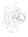
Figure 1 is a perspective view of a clothes tumble dryer according to the invention; -
Figure 2 is a perspective enlarged view of a detail offigure 1 ; -
Figure 3 is a perspective view of the drum offigure 2 from the opposite direction, i.e. from outside; -
Figure 4 is a partial cross sectioned view of a detail offigure 2 ; -
Figure 5 is a front view of the perforated rear wall of the drum where the shape of the distributor is shown in solid and dotted line; and -
Figure 6 is a schematic view of how a clothes dryer according to the invention works. - With reference to
figure 1 , a tumble dryer 10 according to the invention comprises acabinet 12 having an upper wall 12a, afront wall 12b provided with a hingedly mounteddoor 14, side walls 12c and a rear wall 12d. Inside the cabinet 12 a rotatingdrum 16 is mounted which is actuated by an electric motor (not shown) and which defines adrying chamber 17. Thedrum 16 includes at least onehollow lifter 18 having a plurality ofholes 20 for air passage. Thelifter 18 presents arear base portion 18a having a triangular shape (circular sector) which covers a portion of a rear perforatedwall 16a of the drum in order to convey air entering through such perforated wall towards the holes of thelifter 18. Thebase portion 18a defines with the facing portion of therear wall 16a of the drum a sort ofinner chamber 19 which covers an arc ranging preferably from 60 to 100° and which communicates with the portion of thelifter 18 fixed to the side wall of thedrum 16. The clothes dryer 10 may also have a dispensing system for dispensing treating chemistries into thedrum 16, and including areservoir 22 that is closed by acover 24. The clothes dryer 10 is also provided with acontroller 26 that may receive input from a user through auser interface 28 for selecting a cycle of operation. - The clothes dryer comprises also an air inlet channel 30 (
figure 6 ) and anoutlet channel 32, an heating system (not shown) that heats air entering the drum (e.g. by means of resistors, heat exchangers, etc.), and a blower (not shown) that makes air flowing across thedrum 16. - The
drum outlet 32, where aremovable filter 33 for removing fluff is placed, can be eventually connected to thedrum inlet 30 thus realizing a closed loop system in which heat exchangers, resistors, heat pump, etc.. control the condensation and heating process. As an alternative the drum outlet can be connected to an air vent. - According to the present invention, the lifter function is not only to increase the heat exchange efficiency between air and clothes and improve the evenness of the drying result by means of clothes redistribution during the whole cycle, but also to improve the efficiency of hot air distribution.
- A common drawback of known dryers is that when the load size increases to almost fill the drum volume, the efficiency of the lifter in redistributing the load within the drum is decreased thus leading to the risk of damaging the clothes that are positioned in the rear end of the dryer (where temperatures are higher) and reducing the evenness of drying results.
- With a lifter design that allows not only the hot air to flow through the
lifter 18 but also by means of a distribution of air through the lifter only during a certain degree of rotation of the drum, the temperature gradient in the drum is reduced and the evenness of drying is increased, reducing also the risk of clothes damaging. - The above controlled distribution is carried out by means of a shaped
fixed distributor 34 which forms an air inlet plenum chamber upstream thedrum 16. The shape of the distributor 34 (figure 5 ) does not corresponds necessarily to the circular sector shape of thebase portion 18a of thelifter 18, but preferably it does not extend higher than the lower half of the drum. Infigure 5 two shapes are shown (in dotted and solid lines) which have worked well in tests carried out by the applicant. Such shapes maximize the air flow either though the lifter 18 (when this latter is in the lower positions during rotation) and through clothes adjacent the lifter. - According to a second aspect of the invention, the enhanced lifter design can be combined with a dedicated cycle design, able to stop tumbling when one of the
lifter 18 is located in such position to minimize the temperature gradient. This approach can furthermore increase the above mentioned advantages and can provide also energy saving benefits due to reduced motor usage. The solution according to the invention uses one or more lifters of the type described above that can also be used together with more typical lifter that do not match the above description. Due to the fact that the lifter is physically connected to the drum, during tumbling it changes its position with respect to theair inlet 34 thus leading to a variable air mass flow rate in the lifter and in the drum. This is clearly shown infigure 6 where arrows A show the air flow through the lifter 18 (when this latter is placed in the lower position inside the drum 16) and arrows B show the air flow through therear wall 16a of thedrum 16 when the lifter is in other position not matching theair distributor 34. This alternating air flow path in the drum creates the conditions for a variable heat flux as well that improves the evenness of drying and fabric care. - Furthermore the present invention can improve significantly also the drying and fabric care performances with delicate cycles. As described above, aiming to reduce the mechanical action on this type of loads, the tumbling is often reduced or even avoided; this solution has the negative result of increasing the temperature gradient thus leading to the already discussed drawbacks. If the proposed lifter design is used, the machine can be designed to stop tumbling process (for the whole cycle or only for part of it, also e.g. using a PWM approach) in a way that the air can flow through the
lifter 18 so providing a means to optimize heat flux for these type of load using appropriate design of the lifter. In a preferred embodiment of the invention thedrum 16 is in such position that thelifter 18 lays on the bottom of the drum, thus having the clothes laying on it. The method used to stop the drum in the correct position is well known in the art and it can be easily transferred from the known solutions for top loader washer for having the door in upwards location to facilitate loading and unloading of the drum. - Moreover, since air can flow through the lifter, the latter can be designed to host a cartridge containing a fragrance or some other chemical additives to improve quality of drying that can be released in the drum.
- In another preferred embodiment of the invention, the
lifter 18 is used with adrum 16 having process air inlet and outlet port on opposite sides thus enabling fine optimization of heat fluxes. Nevertheless the invention can be applied also to those drums in which inlet and outlet air connections are located on the same side (with a dedicated air collector similar to air distributor 34). In this case the lifter can be used to convey hot inlet air towards the opposite side of the drum, therefore improving significantly the heat flux distribution in the longitudinal direction. - In
figure 4 it is shown a detail of theair distributor 34 which is made preferably by a shaped metal orplastic sheet 35. In order to increase the efficiency sealing means (not shown) can be interposed between the edge of theshaped sheet 35 forming thedistributor 34 and therear wall 16a of the drum.
Claims (12)
- Domestic clothes dryer (10) comprising a rotating drum (16) defining a drying chamber (17), an air inlet (34) upstream the drum (16) and at least a hollow lifter (18) mounted in the drum (16), wherein said hollow lifter (18) is in communication with said air inlet (34) for distributing air inside the drum (16) through a plurality of openings (20), characterized in that the air inlet comprises a distribution device (34) for delivering air to said lifter (18) and/or directly to the drum (16) through a rear perforated wall (16a) thereof.
- Domestic clothes dryer according to claim 1, wherein the distribution device is a shaped air plenum chamber (34, 35) facing a lower portion of the rear perforated wall (16a) of the drum (16).
- Domestic clothes dryer according to claim 2, wherein said hollow lifter (18) has a base part mounted on a portion of the rear perforated wall (16a) of the drum (16) in order to create an inner chamber (19).
- Domestic clothes dryer according to claim 3, wherein said base part (18a) of the hollow lifter (18) has a circular sector shape.
- Domestic clothes dryer according to claim 4, wherein said base part (18a) of the hollow lifter (18) covers an arc comprised between 60° and 100°.
- Domestic clothes dryer according to claim 4 or 5, wherein said shaped air plenum chamber (34, 35) has a shape corresponding substantially to the shape of the base part (18a) of the hollow lifter (18).
- Domestic clothes dryer according to claim 6, wherein said shaped air plenum chamber (34, 35) is positioned in a lower portion with reference to the drying chamber (17).
- Domestic clothes dryer according to any of the preceding claims, wherein it comprises a control circuit (26) capable of stopping the rotation of the drum (16) when the lifter (18) is in the lower position of the drying chamber (17).
- Domestic clothes dryer according to any of the preceding claims, wherein the hollow lifter (18) contains a removable cartridge or the like containing an additive.
- Method for drying clothes in a clothes drying comprising a rotating drum (16) defining a drying chamber, an air inlet (34) upstream the drum (16) and at least a hollow lifter (18) mounted in the drum (16), wherein said hollow lifter (18) is in communication with said air inlet (34) for distributing air inside the drum (16) the drum (16) through a plurality of openings (20), characterized in that the drum (16) is stopped for a predetermined time when the lifter (18) is in its low position in the drying chamber (17).
- Method according to claim 10, wherein the rotation of the drum is according to a certain pattern according to which the drum is repeatedly stopped when the lifter (18) reaches said low position.
- Method according to claim 10, wherein the drum is maintained for whole or major portion of the drying cycle in an idle configuration with the hollow liter (18) positioned in its low position in the drying chamber (17).
Priority Applications (5)
| Application Number | Priority Date | Filing Date | Title |
|---|---|---|---|
| EP13154316.7A EP2765234B1 (en) | 2013-02-07 | 2013-02-07 | Domestic clothes dryer and method for driving such dryer |
| US14/173,166 US20140215847A1 (en) | 2013-02-07 | 2014-02-05 | Domestic clothes dryer and method for driving such dryers |
| US15/586,827 US10501885B2 (en) | 2013-02-07 | 2017-05-04 | Domestic clothes dryer and method for driving such dryers |
| US16/674,592 US11261559B2 (en) | 2013-02-07 | 2019-11-05 | Domestic clothes dryer and method for driving such dryers |
| US17/582,054 US20220145521A1 (en) | 2013-02-07 | 2022-01-24 | Domestic clothes dryer and method for driving such dryers |
Applications Claiming Priority (1)
| Application Number | Priority Date | Filing Date | Title |
|---|---|---|---|
| EP13154316.7A EP2765234B1 (en) | 2013-02-07 | 2013-02-07 | Domestic clothes dryer and method for driving such dryer |
Publications (2)
| Publication Number | Publication Date |
|---|---|
| EP2765234A1 true EP2765234A1 (en) | 2014-08-13 |
| EP2765234B1 EP2765234B1 (en) | 2017-08-23 |
Family
ID=47720336
Family Applications (1)
| Application Number | Title | Priority Date | Filing Date |
|---|---|---|---|
| EP13154316.7A Active EP2765234B1 (en) | 2013-02-07 | 2013-02-07 | Domestic clothes dryer and method for driving such dryer |
Country Status (2)
| Country | Link |
|---|---|
| US (4) | US20140215847A1 (en) |
| EP (1) | EP2765234B1 (en) |
Cited By (1)
| Publication number | Priority date | Publication date | Assignee | Title |
|---|---|---|---|---|
| WO2019038016A1 (en) | 2017-08-25 | 2019-02-28 | Arcelik Anonim Sirketi | A laundry drying machine with improved drying performance |
Families Citing this family (8)
| Publication number | Priority date | Publication date | Assignee | Title |
|---|---|---|---|---|
| USD789630S1 (en) * | 2015-02-24 | 2017-06-13 | Samsung Electronics Co., Ltd. | Drum lifter for drum washing machine |
| USD773763S1 (en) * | 2015-02-24 | 2016-12-06 | Samsung Electronics Co., Ltd. | Drum lifter for drum washing machine |
| KR102407646B1 (en) * | 2015-07-17 | 2022-06-10 | 엘지전자 주식회사 | Fabric dryer |
| US11008691B2 (en) | 2018-05-04 | 2021-05-18 | Whirlpool Corporation | Laundry treating appliance having an air flow assembly |
| CN110438725B (en) * | 2018-05-04 | 2022-10-11 | 惠而浦公司 | Combined washing and drying treatment appliance |
| USD942715S1 (en) | 2018-10-08 | 2022-02-01 | Whirlpool Corporation | Fabric care appliance |
| CN111041764B (en) * | 2018-10-11 | 2022-12-20 | 无锡小天鹅电器有限公司 | Clothes treatment device and inner drum assembly of clothes treatment device |
| US20240263379A1 (en) * | 2023-02-06 | 2024-08-08 | Whirlpool Corporation | Multifunction lifter for a laundry appliance |
Citations (4)
| Publication number | Priority date | Publication date | Assignee | Title |
|---|---|---|---|---|
| WO1990015178A1 (en) * | 1989-06-07 | 1990-12-13 | Zanker Gmbh & Co. Ohg | Laundry drier |
| JPH0956991A (en) | 1995-08-18 | 1997-03-04 | Matsushita Electric Ind Co Ltd | Clothes dryer |
| DE19623959A1 (en) * | 1996-04-26 | 1997-12-18 | Aeg Hausgeraete Gmbh | Laundry tumble dryer |
| EP1690974A1 (en) * | 2005-02-10 | 2006-08-16 | Electrolux Home Products Corporation N.V. | Clothes drying machine provided with additive dispensing means |
Family Cites Families (12)
| Publication number | Priority date | Publication date | Assignee | Title |
|---|---|---|---|---|
| US3902254A (en) * | 1973-10-15 | 1975-09-02 | Mc Graw Edison Co | Laundry system with drying tumbler |
| US4971449A (en) * | 1989-12-19 | 1990-11-20 | American Laundry Machinery Inc. | Drum type agitating and mixing machine |
| JP3102637B2 (en) * | 1997-10-08 | 2000-10-23 | エルジー電子株式会社 | Microwave washer / dryer |
| DE19925917A1 (en) * | 1999-06-07 | 2000-12-14 | Bsh Bosch Siemens Hausgeraete | Front loading washing machine with a rotating drum |
| KR100438618B1 (en) * | 2002-01-21 | 2004-07-02 | 엘지전자 주식회사 | Clothing dryer |
| WO2004048673A2 (en) * | 2002-11-22 | 2004-06-10 | Su Heon Kim | Fast clothes dryer and drying method |
| RU2006114770A (en) * | 2003-09-29 | 2007-11-10 | Селф Пропеллед Рисерч энд Дивелопмент Спешелистс,эЛэЛСи (US) | DRYING DEVICE (OPTIONS), WASHING DEVICE AND DRYING CHAMBER (OPTIONS) |
| US20050097927A1 (en) * | 2003-11-10 | 2005-05-12 | Samsung Electronics Co., Ltd. | Drum type washing machine |
| KR20050045256A (en) * | 2003-11-10 | 2005-05-17 | 삼성전자주식회사 | Drum washing machine |
| CA2629495A1 (en) * | 2008-04-18 | 2009-10-18 | Mabe Canada Inc. | Apparatus for controlling a clothes dryer |
| KR20130034911A (en) * | 2011-09-29 | 2013-04-08 | 삼성전자주식회사 | Lifter and washing machine having the same |
| KR102011817B1 (en) * | 2012-12-31 | 2019-08-19 | 엘지전자 주식회사 | Laundry Machine |
-
2013
- 2013-02-07 EP EP13154316.7A patent/EP2765234B1/en active Active
-
2014
- 2014-02-05 US US14/173,166 patent/US20140215847A1/en not_active Abandoned
-
2017
- 2017-05-04 US US15/586,827 patent/US10501885B2/en active Active
-
2019
- 2019-11-05 US US16/674,592 patent/US11261559B2/en active Active
-
2022
- 2022-01-24 US US17/582,054 patent/US20220145521A1/en not_active Abandoned
Patent Citations (4)
| Publication number | Priority date | Publication date | Assignee | Title |
|---|---|---|---|---|
| WO1990015178A1 (en) * | 1989-06-07 | 1990-12-13 | Zanker Gmbh & Co. Ohg | Laundry drier |
| JPH0956991A (en) | 1995-08-18 | 1997-03-04 | Matsushita Electric Ind Co Ltd | Clothes dryer |
| DE19623959A1 (en) * | 1996-04-26 | 1997-12-18 | Aeg Hausgeraete Gmbh | Laundry tumble dryer |
| EP1690974A1 (en) * | 2005-02-10 | 2006-08-16 | Electrolux Home Products Corporation N.V. | Clothes drying machine provided with additive dispensing means |
Cited By (1)
| Publication number | Priority date | Publication date | Assignee | Title |
|---|---|---|---|---|
| WO2019038016A1 (en) | 2017-08-25 | 2019-02-28 | Arcelik Anonim Sirketi | A laundry drying machine with improved drying performance |
Also Published As
| Publication number | Publication date |
|---|---|
| US20170233940A1 (en) | 2017-08-17 |
| US10501885B2 (en) | 2019-12-10 |
| US11261559B2 (en) | 2022-03-01 |
| US20140215847A1 (en) | 2014-08-07 |
| US20200080248A1 (en) | 2020-03-12 |
| US20220145521A1 (en) | 2022-05-12 |
| EP2765234B1 (en) | 2017-08-23 |
Similar Documents
| Publication | Publication Date | Title |
|---|---|---|
| EP2765234B1 (en) | Domestic clothes dryer and method for driving such dryer | |
| US9663894B2 (en) | Steam generator and laundry dryer having the same and controlling method thereof | |
| RU2582469C2 (en) | Linen processing device | |
| EP2386674A2 (en) | Washing machine having drying function and water filter thereof | |
| EP3543393A2 (en) | Clothing treatment apparatus | |
| US8875416B2 (en) | Laundry treating appliance door with planar window element and projection | |
| KR102100473B1 (en) | Clothes treating apparatus with a waste heat recovery means | |
| CN109402985B (en) | Clothes treatment device and clothes treatment method | |
| EP3559331B1 (en) | Clothing drying apparatus | |
| KR100662473B1 (en) | Dryer using steam generator | |
| EP1995371A1 (en) | Electric household appliance | |
| CN115748205A (en) | Drying system of drying equipment, control method and drying equipment | |
| CN101305123B (en) | Steam generator, laundry dryer having same, and control method thereof | |
| US20050155250A1 (en) | Clothes drying apparatus | |
| CN110924042A (en) | laundry treatment device | |
| EP2843126B1 (en) | Laundry treatment apparatus and control method thereof | |
| JP6710858B2 (en) | Drum type washer/dryer and method for drying clothes | |
| WO2015063016A1 (en) | A laundry dryer with increased ventilating effectiveness | |
| EP4424900A1 (en) | Laundry treating apparatus | |
| JP6572434B2 (en) | Clothes dryer | |
| KR200436113Y1 (en) | Fiber dryer | |
| CN112227039A (en) | Clothes drying method | |
| EP1832678B1 (en) | Energy saving household clothes drying machine | |
| CN215447313U (en) | Drying machine on clothing hanging system | |
| CN102653920B (en) | Drying device |
Legal Events
| Date | Code | Title | Description |
|---|---|---|---|
| PUAI | Public reference made under article 153(3) epc to a published international application that has entered the european phase |
Free format text: ORIGINAL CODE: 0009012 |
|
| 17P | Request for examination filed |
Effective date: 20130207 |
|
| AK | Designated contracting states |
Kind code of ref document: A1 Designated state(s): AL AT BE BG CH CY CZ DE DK EE ES FI FR GB GR HR HU IE IS IT LI LT LU LV MC MK MT NL NO PL PT RO RS SE SI SK SM TR |
|
| AX | Request for extension of the european patent |
Extension state: BA ME |
|
| R17P | Request for examination filed (corrected) |
Effective date: 20150212 |
|
| RBV | Designated contracting states (corrected) |
Designated state(s): AL AT BE BG CH CY CZ DE DK EE ES FI FR GB GR HR HU IE IS IT LI LT LU LV MC MK MT NL NO PL PT RO RS SE SI SK SM TR |
|
| 17Q | First examination report despatched |
Effective date: 20150901 |
|
| STAA | Information on the status of an ep patent application or granted ep patent |
Free format text: STATUS: EXAMINATION IS IN PROGRESS |
|
| GRAP | Despatch of communication of intention to grant a patent |
Free format text: ORIGINAL CODE: EPIDOSNIGR1 |
|
| STAA | Information on the status of an ep patent application or granted ep patent |
Free format text: STATUS: GRANT OF PATENT IS INTENDED |
|
| INTG | Intention to grant announced |
Effective date: 20170608 |
|
| RIN1 | Information on inventor provided before grant (corrected) |
Inventor name: PADERNO, JURIJ Inventor name: HASELMEIER, RALF |
|
| GRAS | Grant fee paid |
Free format text: ORIGINAL CODE: EPIDOSNIGR3 |
|
| GRAA | (expected) grant |
Free format text: ORIGINAL CODE: 0009210 |
|
| STAA | Information on the status of an ep patent application or granted ep patent |
Free format text: STATUS: THE PATENT HAS BEEN GRANTED |
|
| AK | Designated contracting states |
Kind code of ref document: B1 Designated state(s): AL AT BE BG CH CY CZ DE DK EE ES FI FR GB GR HR HU IE IS IT LI LT LU LV MC MK MT NL NO PL PT RO RS SE SI SK SM TR |
|
| REG | Reference to a national code |
Ref country code: GB Ref legal event code: FG4D |
|
| REG | Reference to a national code |
Ref country code: CH Ref legal event code: EP |
|
| REG | Reference to a national code |
Ref country code: AT Ref legal event code: REF Ref document number: 921466 Country of ref document: AT Kind code of ref document: T Effective date: 20170915 |
|
| REG | Reference to a national code |
Ref country code: IE Ref legal event code: FG4D |
|
| REG | Reference to a national code |
Ref country code: DE Ref legal event code: R096 Ref document number: 602013025329 Country of ref document: DE |
|
| REG | Reference to a national code |
Ref country code: NL Ref legal event code: MP Effective date: 20170823 |
|
| REG | Reference to a national code |
Ref country code: LT Ref legal event code: MG4D |
|
| REG | Reference to a national code |
Ref country code: FR Ref legal event code: PLFP Year of fee payment: 6 |
|
| REG | Reference to a national code |
Ref country code: AT Ref legal event code: MK05 Ref document number: 921466 Country of ref document: AT Kind code of ref document: T Effective date: 20170823 |
|
| PG25 | Lapsed in a contracting state [announced via postgrant information from national office to epo] |
Ref country code: NO Free format text: LAPSE BECAUSE OF FAILURE TO SUBMIT A TRANSLATION OF THE DESCRIPTION OR TO PAY THE FEE WITHIN THE PRESCRIBED TIME-LIMIT Effective date: 20171123 Ref country code: HR Free format text: LAPSE BECAUSE OF FAILURE TO SUBMIT A TRANSLATION OF THE DESCRIPTION OR TO PAY THE FEE WITHIN THE PRESCRIBED TIME-LIMIT Effective date: 20170823 Ref country code: SE Free format text: LAPSE BECAUSE OF FAILURE TO SUBMIT A TRANSLATION OF THE DESCRIPTION OR TO PAY THE FEE WITHIN THE PRESCRIBED TIME-LIMIT Effective date: 20170823 Ref country code: LT Free format text: LAPSE BECAUSE OF FAILURE TO SUBMIT A TRANSLATION OF THE DESCRIPTION OR TO PAY THE FEE WITHIN THE PRESCRIBED TIME-LIMIT Effective date: 20170823 Ref country code: FI Free format text: LAPSE BECAUSE OF FAILURE TO SUBMIT A TRANSLATION OF THE DESCRIPTION OR TO PAY THE FEE WITHIN THE PRESCRIBED TIME-LIMIT Effective date: 20170823 Ref country code: NL Free format text: LAPSE BECAUSE OF FAILURE TO SUBMIT A TRANSLATION OF THE DESCRIPTION OR TO PAY THE FEE WITHIN THE PRESCRIBED TIME-LIMIT Effective date: 20170823 Ref country code: AT Free format text: LAPSE BECAUSE OF FAILURE TO SUBMIT A TRANSLATION OF THE DESCRIPTION OR TO PAY THE FEE WITHIN THE PRESCRIBED TIME-LIMIT Effective date: 20170823 |
|
| PG25 | Lapsed in a contracting state [announced via postgrant information from national office to epo] |
Ref country code: LV Free format text: LAPSE BECAUSE OF FAILURE TO SUBMIT A TRANSLATION OF THE DESCRIPTION OR TO PAY THE FEE WITHIN THE PRESCRIBED TIME-LIMIT Effective date: 20170823 Ref country code: PL Free format text: LAPSE BECAUSE OF FAILURE TO SUBMIT A TRANSLATION OF THE DESCRIPTION OR TO PAY THE FEE WITHIN THE PRESCRIBED TIME-LIMIT Effective date: 20170823 Ref country code: ES Free format text: LAPSE BECAUSE OF FAILURE TO SUBMIT A TRANSLATION OF THE DESCRIPTION OR TO PAY THE FEE WITHIN THE PRESCRIBED TIME-LIMIT Effective date: 20170823 Ref country code: RS Free format text: LAPSE BECAUSE OF FAILURE TO SUBMIT A TRANSLATION OF THE DESCRIPTION OR TO PAY THE FEE WITHIN THE PRESCRIBED TIME-LIMIT Effective date: 20170823 Ref country code: BG Free format text: LAPSE BECAUSE OF FAILURE TO SUBMIT A TRANSLATION OF THE DESCRIPTION OR TO PAY THE FEE WITHIN THE PRESCRIBED TIME-LIMIT Effective date: 20171123 Ref country code: IS Free format text: LAPSE BECAUSE OF FAILURE TO SUBMIT A TRANSLATION OF THE DESCRIPTION OR TO PAY THE FEE WITHIN THE PRESCRIBED TIME-LIMIT Effective date: 20171223 Ref country code: GR Free format text: LAPSE BECAUSE OF FAILURE TO SUBMIT A TRANSLATION OF THE DESCRIPTION OR TO PAY THE FEE WITHIN THE PRESCRIBED TIME-LIMIT Effective date: 20171124 |
|
| PG25 | Lapsed in a contracting state [announced via postgrant information from national office to epo] |
Ref country code: CZ Free format text: LAPSE BECAUSE OF FAILURE TO SUBMIT A TRANSLATION OF THE DESCRIPTION OR TO PAY THE FEE WITHIN THE PRESCRIBED TIME-LIMIT Effective date: 20170823 Ref country code: RO Free format text: LAPSE BECAUSE OF FAILURE TO SUBMIT A TRANSLATION OF THE DESCRIPTION OR TO PAY THE FEE WITHIN THE PRESCRIBED TIME-LIMIT Effective date: 20170823 Ref country code: DK Free format text: LAPSE BECAUSE OF FAILURE TO SUBMIT A TRANSLATION OF THE DESCRIPTION OR TO PAY THE FEE WITHIN THE PRESCRIBED TIME-LIMIT Effective date: 20170823 |
|
| REG | Reference to a national code |
Ref country code: DE Ref legal event code: R097 Ref document number: 602013025329 Country of ref document: DE |
|
| PG25 | Lapsed in a contracting state [announced via postgrant information from national office to epo] |
Ref country code: EE Free format text: LAPSE BECAUSE OF FAILURE TO SUBMIT A TRANSLATION OF THE DESCRIPTION OR TO PAY THE FEE WITHIN THE PRESCRIBED TIME-LIMIT Effective date: 20170823 Ref country code: SK Free format text: LAPSE BECAUSE OF FAILURE TO SUBMIT A TRANSLATION OF THE DESCRIPTION OR TO PAY THE FEE WITHIN THE PRESCRIBED TIME-LIMIT Effective date: 20170823 Ref country code: SM Free format text: LAPSE BECAUSE OF FAILURE TO SUBMIT A TRANSLATION OF THE DESCRIPTION OR TO PAY THE FEE WITHIN THE PRESCRIBED TIME-LIMIT Effective date: 20170823 |
|
| PLBE | No opposition filed within time limit |
Free format text: ORIGINAL CODE: 0009261 |
|
| STAA | Information on the status of an ep patent application or granted ep patent |
Free format text: STATUS: NO OPPOSITION FILED WITHIN TIME LIMIT |
|
| 26N | No opposition filed |
Effective date: 20180524 |
|
| PG25 | Lapsed in a contracting state [announced via postgrant information from national office to epo] |
Ref country code: SI Free format text: LAPSE BECAUSE OF FAILURE TO SUBMIT A TRANSLATION OF THE DESCRIPTION OR TO PAY THE FEE WITHIN THE PRESCRIBED TIME-LIMIT Effective date: 20170823 |
|
| REG | Reference to a national code |
Ref country code: CH Ref legal event code: PL |
|
| PG25 | Lapsed in a contracting state [announced via postgrant information from national office to epo] |
Ref country code: MC Free format text: LAPSE BECAUSE OF FAILURE TO SUBMIT A TRANSLATION OF THE DESCRIPTION OR TO PAY THE FEE WITHIN THE PRESCRIBED TIME-LIMIT Effective date: 20170823 |
|
| REG | Reference to a national code |
Ref country code: IE Ref legal event code: MM4A |
|
| REG | Reference to a national code |
Ref country code: BE Ref legal event code: MM Effective date: 20180228 |
|
| PG25 | Lapsed in a contracting state [announced via postgrant information from national office to epo] |
Ref country code: CH Free format text: LAPSE BECAUSE OF NON-PAYMENT OF DUE FEES Effective date: 20180228 Ref country code: LU Free format text: LAPSE BECAUSE OF NON-PAYMENT OF DUE FEES Effective date: 20180207 Ref country code: LI Free format text: LAPSE BECAUSE OF NON-PAYMENT OF DUE FEES Effective date: 20180228 |
|
| PG25 | Lapsed in a contracting state [announced via postgrant information from national office to epo] |
Ref country code: IE Free format text: LAPSE BECAUSE OF NON-PAYMENT OF DUE FEES Effective date: 20180207 |
|
| PG25 | Lapsed in a contracting state [announced via postgrant information from national office to epo] |
Ref country code: BE Free format text: LAPSE BECAUSE OF NON-PAYMENT OF DUE FEES Effective date: 20180228 |
|
| PG25 | Lapsed in a contracting state [announced via postgrant information from national office to epo] |
Ref country code: MT Free format text: LAPSE BECAUSE OF NON-PAYMENT OF DUE FEES Effective date: 20180207 |
|
| PG25 | Lapsed in a contracting state [announced via postgrant information from national office to epo] |
Ref country code: TR Free format text: LAPSE BECAUSE OF FAILURE TO SUBMIT A TRANSLATION OF THE DESCRIPTION OR TO PAY THE FEE WITHIN THE PRESCRIBED TIME-LIMIT Effective date: 20170823 |
|
| PG25 | Lapsed in a contracting state [announced via postgrant information from national office to epo] |
Ref country code: PT Free format text: LAPSE BECAUSE OF FAILURE TO SUBMIT A TRANSLATION OF THE DESCRIPTION OR TO PAY THE FEE WITHIN THE PRESCRIBED TIME-LIMIT Effective date: 20170823 Ref country code: HU Free format text: LAPSE BECAUSE OF FAILURE TO SUBMIT A TRANSLATION OF THE DESCRIPTION OR TO PAY THE FEE WITHIN THE PRESCRIBED TIME-LIMIT; INVALID AB INITIO Effective date: 20130207 |
|
| PG25 | Lapsed in a contracting state [announced via postgrant information from national office to epo] |
Ref country code: MK Free format text: LAPSE BECAUSE OF NON-PAYMENT OF DUE FEES Effective date: 20170823 Ref country code: CY Free format text: LAPSE BECAUSE OF FAILURE TO SUBMIT A TRANSLATION OF THE DESCRIPTION OR TO PAY THE FEE WITHIN THE PRESCRIBED TIME-LIMIT Effective date: 20170823 |
|
| PG25 | Lapsed in a contracting state [announced via postgrant information from national office to epo] |
Ref country code: AL Free format text: LAPSE BECAUSE OF FAILURE TO SUBMIT A TRANSLATION OF THE DESCRIPTION OR TO PAY THE FEE WITHIN THE PRESCRIBED TIME-LIMIT Effective date: 20170823 |
|
| P01 | Opt-out of the competence of the unified patent court (upc) registered |
Effective date: 20230522 |
|
| PGFP | Annual fee paid to national office [announced via postgrant information from national office to epo] |
Ref country code: GB Payment date: 20260122 Year of fee payment: 14 |
|
| PGFP | Annual fee paid to national office [announced via postgrant information from national office to epo] |
Ref country code: DE Payment date: 20260220 Year of fee payment: 14 |
|
| PGFP | Annual fee paid to national office [announced via postgrant information from national office to epo] |
Ref country code: IT Payment date: 20260204 Year of fee payment: 14 |
|
| PGFP | Annual fee paid to national office [announced via postgrant information from national office to epo] |
Ref country code: FR Payment date: 20260227 Year of fee payment: 14 |