EP2765022A2 - Charging apparatus and electric vehicle including the same - Google Patents
Charging apparatus and electric vehicle including the same Download PDFInfo
- Publication number
- EP2765022A2 EP2765022A2 EP14154212.6A EP14154212A EP2765022A2 EP 2765022 A2 EP2765022 A2 EP 2765022A2 EP 14154212 A EP14154212 A EP 14154212A EP 2765022 A2 EP2765022 A2 EP 2765022A2
- Authority
- EP
- European Patent Office
- Prior art keywords
- motor
- switching
- phase
- voltage
- inverter
- Prior art date
- Legal status (The legal status is an assumption and is not a legal conclusion. Google has not performed a legal analysis and makes no representation as to the accuracy of the status listed.)
- Withdrawn
Links
- 239000013598 vector Substances 0.000 claims description 12
- 230000004907 flux Effects 0.000 claims description 8
- 239000003990 capacitor Substances 0.000 description 36
- 238000010586 diagram Methods 0.000 description 16
- 230000009466 transformation Effects 0.000 description 12
- 238000002485 combustion reaction Methods 0.000 description 7
- 238000000034 method Methods 0.000 description 7
- 238000009499 grossing Methods 0.000 description 5
- 239000000725 suspension Substances 0.000 description 5
- 230000033001 locomotion Effects 0.000 description 3
- 230000008901 benefit Effects 0.000 description 2
- 230000005611 electricity Effects 0.000 description 2
- 238000007792 addition Methods 0.000 description 1
- 230000005540 biological transmission Effects 0.000 description 1
- 230000003247 decreasing effect Effects 0.000 description 1
- 238000001514 detection method Methods 0.000 description 1
- 238000007599 discharging Methods 0.000 description 1
- 230000005684 electric field Effects 0.000 description 1
- 238000003912 environmental pollution Methods 0.000 description 1
- 230000006698 induction Effects 0.000 description 1
- 238000012986 modification Methods 0.000 description 1
- 230000004048 modification Effects 0.000 description 1
- 230000007935 neutral effect Effects 0.000 description 1
- 238000006467 substitution reaction Methods 0.000 description 1
Images


Classifications
-
- B—PERFORMING OPERATIONS; TRANSPORTING
- B60—VEHICLES IN GENERAL
- B60L—PROPULSION OF ELECTRICALLY-PROPELLED VEHICLES; SUPPLYING ELECTRIC POWER FOR AUXILIARY EQUIPMENT OF ELECTRICALLY-PROPELLED VEHICLES; ELECTRODYNAMIC BRAKE SYSTEMS FOR VEHICLES IN GENERAL; MAGNETIC SUSPENSION OR LEVITATION FOR VEHICLES; MONITORING OPERATING VARIABLES OF ELECTRICALLY-PROPELLED VEHICLES; ELECTRIC SAFETY DEVICES FOR ELECTRICALLY-PROPELLED VEHICLES
- B60L53/00—Methods of charging batteries, specially adapted for electric vehicles; Charging stations or on-board charging equipment therefor; Exchange of energy storage elements in electric vehicles
- B60L53/20—Methods of charging batteries, specially adapted for electric vehicles; Charging stations or on-board charging equipment therefor; Exchange of energy storage elements in electric vehicles characterised by converters located in the vehicle
-
- B—PERFORMING OPERATIONS; TRANSPORTING
- B60—VEHICLES IN GENERAL
- B60L—PROPULSION OF ELECTRICALLY-PROPELLED VEHICLES; SUPPLYING ELECTRIC POWER FOR AUXILIARY EQUIPMENT OF ELECTRICALLY-PROPELLED VEHICLES; ELECTRODYNAMIC BRAKE SYSTEMS FOR VEHICLES IN GENERAL; MAGNETIC SUSPENSION OR LEVITATION FOR VEHICLES; MONITORING OPERATING VARIABLES OF ELECTRICALLY-PROPELLED VEHICLES; ELECTRIC SAFETY DEVICES FOR ELECTRICALLY-PROPELLED VEHICLES
- B60L15/00—Methods, circuits, or devices for controlling the traction-motor speed of electrically-propelled vehicles
- B60L15/02—Methods, circuits, or devices for controlling the traction-motor speed of electrically-propelled vehicles characterised by the form of the current used in the control circuit
- B60L15/025—Methods, circuits, or devices for controlling the traction-motor speed of electrically-propelled vehicles characterised by the form of the current used in the control circuit using field orientation; Vector control; Direct Torque Control [DTC]
-
- B—PERFORMING OPERATIONS; TRANSPORTING
- B60—VEHICLES IN GENERAL
- B60L—PROPULSION OF ELECTRICALLY-PROPELLED VEHICLES; SUPPLYING ELECTRIC POWER FOR AUXILIARY EQUIPMENT OF ELECTRICALLY-PROPELLED VEHICLES; ELECTRODYNAMIC BRAKE SYSTEMS FOR VEHICLES IN GENERAL; MAGNETIC SUSPENSION OR LEVITATION FOR VEHICLES; MONITORING OPERATING VARIABLES OF ELECTRICALLY-PROPELLED VEHICLES; ELECTRIC SAFETY DEVICES FOR ELECTRICALLY-PROPELLED VEHICLES
- B60L53/00—Methods of charging batteries, specially adapted for electric vehicles; Charging stations or on-board charging equipment therefor; Exchange of energy storage elements in electric vehicles
- B60L53/20—Methods of charging batteries, specially adapted for electric vehicles; Charging stations or on-board charging equipment therefor; Exchange of energy storage elements in electric vehicles characterised by converters located in the vehicle
- B60L53/22—Constructional details or arrangements of charging converters specially adapted for charging electric vehicles
-
- B—PERFORMING OPERATIONS; TRANSPORTING
- B60—VEHICLES IN GENERAL
- B60L—PROPULSION OF ELECTRICALLY-PROPELLED VEHICLES; SUPPLYING ELECTRIC POWER FOR AUXILIARY EQUIPMENT OF ELECTRICALLY-PROPELLED VEHICLES; ELECTRODYNAMIC BRAKE SYSTEMS FOR VEHICLES IN GENERAL; MAGNETIC SUSPENSION OR LEVITATION FOR VEHICLES; MONITORING OPERATING VARIABLES OF ELECTRICALLY-PROPELLED VEHICLES; ELECTRIC SAFETY DEVICES FOR ELECTRICALLY-PROPELLED VEHICLES
- B60L53/00—Methods of charging batteries, specially adapted for electric vehicles; Charging stations or on-board charging equipment therefor; Exchange of energy storage elements in electric vehicles
- B60L53/20—Methods of charging batteries, specially adapted for electric vehicles; Charging stations or on-board charging equipment therefor; Exchange of energy storage elements in electric vehicles characterised by converters located in the vehicle
- B60L53/24—Using the vehicle's propulsion converter for charging
-
- B—PERFORMING OPERATIONS; TRANSPORTING
- B60—VEHICLES IN GENERAL
- B60L—PROPULSION OF ELECTRICALLY-PROPELLED VEHICLES; SUPPLYING ELECTRIC POWER FOR AUXILIARY EQUIPMENT OF ELECTRICALLY-PROPELLED VEHICLES; ELECTRODYNAMIC BRAKE SYSTEMS FOR VEHICLES IN GENERAL; MAGNETIC SUSPENSION OR LEVITATION FOR VEHICLES; MONITORING OPERATING VARIABLES OF ELECTRICALLY-PROPELLED VEHICLES; ELECTRIC SAFETY DEVICES FOR ELECTRICALLY-PROPELLED VEHICLES
- B60L2210/00—Converter types
- B60L2210/10—DC to DC converters
- B60L2210/12—Buck converters
-
- B—PERFORMING OPERATIONS; TRANSPORTING
- B60—VEHICLES IN GENERAL
- B60L—PROPULSION OF ELECTRICALLY-PROPELLED VEHICLES; SUPPLYING ELECTRIC POWER FOR AUXILIARY EQUIPMENT OF ELECTRICALLY-PROPELLED VEHICLES; ELECTRODYNAMIC BRAKE SYSTEMS FOR VEHICLES IN GENERAL; MAGNETIC SUSPENSION OR LEVITATION FOR VEHICLES; MONITORING OPERATING VARIABLES OF ELECTRICALLY-PROPELLED VEHICLES; ELECTRIC SAFETY DEVICES FOR ELECTRICALLY-PROPELLED VEHICLES
- B60L2210/00—Converter types
- B60L2210/10—DC to DC converters
- B60L2210/14—Boost converters
-
- B—PERFORMING OPERATIONS; TRANSPORTING
- B60—VEHICLES IN GENERAL
- B60L—PROPULSION OF ELECTRICALLY-PROPELLED VEHICLES; SUPPLYING ELECTRIC POWER FOR AUXILIARY EQUIPMENT OF ELECTRICALLY-PROPELLED VEHICLES; ELECTRODYNAMIC BRAKE SYSTEMS FOR VEHICLES IN GENERAL; MAGNETIC SUSPENSION OR LEVITATION FOR VEHICLES; MONITORING OPERATING VARIABLES OF ELECTRICALLY-PROPELLED VEHICLES; ELECTRIC SAFETY DEVICES FOR ELECTRICALLY-PROPELLED VEHICLES
- B60L2210/00—Converter types
- B60L2210/40—DC to AC converters
-
- B—PERFORMING OPERATIONS; TRANSPORTING
- B60—VEHICLES IN GENERAL
- B60L—PROPULSION OF ELECTRICALLY-PROPELLED VEHICLES; SUPPLYING ELECTRIC POWER FOR AUXILIARY EQUIPMENT OF ELECTRICALLY-PROPELLED VEHICLES; ELECTRODYNAMIC BRAKE SYSTEMS FOR VEHICLES IN GENERAL; MAGNETIC SUSPENSION OR LEVITATION FOR VEHICLES; MONITORING OPERATING VARIABLES OF ELECTRICALLY-PROPELLED VEHICLES; ELECTRIC SAFETY DEVICES FOR ELECTRICALLY-PROPELLED VEHICLES
- B60L2220/00—Electrical machine types; Structures or applications thereof
- B60L2220/50—Structural details of electrical machines
- B60L2220/54—Windings for different functions
-
- B—PERFORMING OPERATIONS; TRANSPORTING
- B60—VEHICLES IN GENERAL
- B60L—PROPULSION OF ELECTRICALLY-PROPELLED VEHICLES; SUPPLYING ELECTRIC POWER FOR AUXILIARY EQUIPMENT OF ELECTRICALLY-PROPELLED VEHICLES; ELECTRODYNAMIC BRAKE SYSTEMS FOR VEHICLES IN GENERAL; MAGNETIC SUSPENSION OR LEVITATION FOR VEHICLES; MONITORING OPERATING VARIABLES OF ELECTRICALLY-PROPELLED VEHICLES; ELECTRIC SAFETY DEVICES FOR ELECTRICALLY-PROPELLED VEHICLES
- B60L2240/00—Control parameters of input or output; Target parameters
- B60L2240/10—Vehicle control parameters
- B60L2240/12—Speed
-
- B—PERFORMING OPERATIONS; TRANSPORTING
- B60—VEHICLES IN GENERAL
- B60L—PROPULSION OF ELECTRICALLY-PROPELLED VEHICLES; SUPPLYING ELECTRIC POWER FOR AUXILIARY EQUIPMENT OF ELECTRICALLY-PROPELLED VEHICLES; ELECTRODYNAMIC BRAKE SYSTEMS FOR VEHICLES IN GENERAL; MAGNETIC SUSPENSION OR LEVITATION FOR VEHICLES; MONITORING OPERATING VARIABLES OF ELECTRICALLY-PROPELLED VEHICLES; ELECTRIC SAFETY DEVICES FOR ELECTRICALLY-PROPELLED VEHICLES
- B60L2240/00—Control parameters of input or output; Target parameters
- B60L2240/40—Drive Train control parameters
- B60L2240/42—Drive Train control parameters related to electric machines
- B60L2240/423—Torque
-
- H—ELECTRICITY
- H02—GENERATION; CONVERSION OR DISTRIBUTION OF ELECTRIC POWER
- H02M—APPARATUS FOR CONVERSION BETWEEN AC AND AC, BETWEEN AC AND DC, OR BETWEEN DC AND DC, AND FOR USE WITH MAINS OR SIMILAR POWER SUPPLY SYSTEMS; CONVERSION OF DC OR AC INPUT POWER INTO SURGE OUTPUT POWER; CONTROL OR REGULATION THEREOF
- H02M1/00—Details of apparatus for conversion
- H02M1/0067—Converter structures employing plural converter units, other than for parallel operation of the units on a single load
- H02M1/007—Plural converter units in cascade
-
- H—ELECTRICITY
- H02—GENERATION; CONVERSION OR DISTRIBUTION OF ELECTRIC POWER
- H02M—APPARATUS FOR CONVERSION BETWEEN AC AND AC, BETWEEN AC AND DC, OR BETWEEN DC AND DC, AND FOR USE WITH MAINS OR SIMILAR POWER SUPPLY SYSTEMS; CONVERSION OF DC OR AC INPUT POWER INTO SURGE OUTPUT POWER; CONTROL OR REGULATION THEREOF
- H02M3/00—Conversion of DC power input into DC power output
- H02M3/02—Conversion of DC power input into DC power output without intermediate conversion into AC
- H02M3/04—Conversion of DC power input into DC power output without intermediate conversion into AC by static converters
- H02M3/10—Conversion of DC power input into DC power output without intermediate conversion into AC by static converters using discharge tubes with control electrode or semiconductor devices with control electrode
- H02M3/145—Conversion of DC power input into DC power output without intermediate conversion into AC by static converters using discharge tubes with control electrode or semiconductor devices with control electrode using devices of a triode or transistor type requiring continuous application of a control signal
- H02M3/155—Conversion of DC power input into DC power output without intermediate conversion into AC by static converters using discharge tubes with control electrode or semiconductor devices with control electrode using devices of a triode or transistor type requiring continuous application of a control signal using semiconductor devices only
- H02M3/156—Conversion of DC power input into DC power output without intermediate conversion into AC by static converters using discharge tubes with control electrode or semiconductor devices with control electrode using devices of a triode or transistor type requiring continuous application of a control signal using semiconductor devices only with automatic control of output voltage or current, e.g. switching regulators
- H02M3/158—Conversion of DC power input into DC power output without intermediate conversion into AC by static converters using discharge tubes with control electrode or semiconductor devices with control electrode using devices of a triode or transistor type requiring continuous application of a control signal using semiconductor devices only with automatic control of output voltage or current, e.g. switching regulators including plural semiconductor devices as final control devices for a single load
- H02M3/1582—Buck-boost converters
-
- H—ELECTRICITY
- H02—GENERATION; CONVERSION OR DISTRIBUTION OF ELECTRIC POWER
- H02M—APPARATUS FOR CONVERSION BETWEEN AC AND AC, BETWEEN AC AND DC, OR BETWEEN DC AND DC, AND FOR USE WITH MAINS OR SIMILAR POWER SUPPLY SYSTEMS; CONVERSION OF DC OR AC INPUT POWER INTO SURGE OUTPUT POWER; CONTROL OR REGULATION THEREOF
- H02M3/00—Conversion of DC power input into DC power output
- H02M3/02—Conversion of DC power input into DC power output without intermediate conversion into AC
- H02M3/04—Conversion of DC power input into DC power output without intermediate conversion into AC by static converters
- H02M3/10—Conversion of DC power input into DC power output without intermediate conversion into AC by static converters using discharge tubes with control electrode or semiconductor devices with control electrode
- H02M3/145—Conversion of DC power input into DC power output without intermediate conversion into AC by static converters using discharge tubes with control electrode or semiconductor devices with control electrode using devices of a triode or transistor type requiring continuous application of a control signal
- H02M3/155—Conversion of DC power input into DC power output without intermediate conversion into AC by static converters using discharge tubes with control electrode or semiconductor devices with control electrode using devices of a triode or transistor type requiring continuous application of a control signal using semiconductor devices only
- H02M3/156—Conversion of DC power input into DC power output without intermediate conversion into AC by static converters using discharge tubes with control electrode or semiconductor devices with control electrode using devices of a triode or transistor type requiring continuous application of a control signal using semiconductor devices only with automatic control of output voltage or current, e.g. switching regulators
- H02M3/158—Conversion of DC power input into DC power output without intermediate conversion into AC by static converters using discharge tubes with control electrode or semiconductor devices with control electrode using devices of a triode or transistor type requiring continuous application of a control signal using semiconductor devices only with automatic control of output voltage or current, e.g. switching regulators including plural semiconductor devices as final control devices for a single load
- H02M3/1584—Conversion of DC power input into DC power output without intermediate conversion into AC by static converters using discharge tubes with control electrode or semiconductor devices with control electrode using devices of a triode or transistor type requiring continuous application of a control signal using semiconductor devices only with automatic control of output voltage or current, e.g. switching regulators including plural semiconductor devices as final control devices for a single load with a plurality of power processing stages connected in parallel
-
- H—ELECTRICITY
- H02—GENERATION; CONVERSION OR DISTRIBUTION OF ELECTRIC POWER
- H02M—APPARATUS FOR CONVERSION BETWEEN AC AND AC, BETWEEN AC AND DC, OR BETWEEN DC AND DC, AND FOR USE WITH MAINS OR SIMILAR POWER SUPPLY SYSTEMS; CONVERSION OF DC OR AC INPUT POWER INTO SURGE OUTPUT POWER; CONTROL OR REGULATION THEREOF
- H02M7/00—Conversion of AC power input into DC power output; Conversion of DC power input into AC power output
- H02M7/02—Conversion of AC power input into DC power output without possibility of reversal
- H02M7/04—Conversion of AC power input into DC power output without possibility of reversal by static converters
- H02M7/06—Conversion of AC power input into DC power output without possibility of reversal by static converters using discharge tubes without control electrode or semiconductor devices without control electrode
-
- Y—GENERAL TAGGING OF NEW TECHNOLOGICAL DEVELOPMENTS; GENERAL TAGGING OF CROSS-SECTIONAL TECHNOLOGIES SPANNING OVER SEVERAL SECTIONS OF THE IPC; TECHNICAL SUBJECTS COVERED BY FORMER USPC CROSS-REFERENCE ART COLLECTIONS [XRACs] AND DIGESTS
- Y02—TECHNOLOGIES OR APPLICATIONS FOR MITIGATION OR ADAPTATION AGAINST CLIMATE CHANGE
- Y02T—CLIMATE CHANGE MITIGATION TECHNOLOGIES RELATED TO TRANSPORTATION
- Y02T10/00—Road transport of goods or passengers
- Y02T10/60—Other road transportation technologies with climate change mitigation effect
- Y02T10/64—Electric machine technologies in electromobility
-
- Y—GENERAL TAGGING OF NEW TECHNOLOGICAL DEVELOPMENTS; GENERAL TAGGING OF CROSS-SECTIONAL TECHNOLOGIES SPANNING OVER SEVERAL SECTIONS OF THE IPC; TECHNICAL SUBJECTS COVERED BY FORMER USPC CROSS-REFERENCE ART COLLECTIONS [XRACs] AND DIGESTS
- Y02—TECHNOLOGIES OR APPLICATIONS FOR MITIGATION OR ADAPTATION AGAINST CLIMATE CHANGE
- Y02T—CLIMATE CHANGE MITIGATION TECHNOLOGIES RELATED TO TRANSPORTATION
- Y02T10/00—Road transport of goods or passengers
- Y02T10/60—Other road transportation technologies with climate change mitigation effect
- Y02T10/70—Energy storage systems for electromobility, e.g. batteries
-
- Y—GENERAL TAGGING OF NEW TECHNOLOGICAL DEVELOPMENTS; GENERAL TAGGING OF CROSS-SECTIONAL TECHNOLOGIES SPANNING OVER SEVERAL SECTIONS OF THE IPC; TECHNICAL SUBJECTS COVERED BY FORMER USPC CROSS-REFERENCE ART COLLECTIONS [XRACs] AND DIGESTS
- Y02—TECHNOLOGIES OR APPLICATIONS FOR MITIGATION OR ADAPTATION AGAINST CLIMATE CHANGE
- Y02T—CLIMATE CHANGE MITIGATION TECHNOLOGIES RELATED TO TRANSPORTATION
- Y02T10/00—Road transport of goods or passengers
- Y02T10/60—Other road transportation technologies with climate change mitigation effect
- Y02T10/7072—Electromobility specific charging systems or methods for batteries, ultracapacitors, supercapacitors or double-layer capacitors
-
- Y—GENERAL TAGGING OF NEW TECHNOLOGICAL DEVELOPMENTS; GENERAL TAGGING OF CROSS-SECTIONAL TECHNOLOGIES SPANNING OVER SEVERAL SECTIONS OF THE IPC; TECHNICAL SUBJECTS COVERED BY FORMER USPC CROSS-REFERENCE ART COLLECTIONS [XRACs] AND DIGESTS
- Y02—TECHNOLOGIES OR APPLICATIONS FOR MITIGATION OR ADAPTATION AGAINST CLIMATE CHANGE
- Y02T—CLIMATE CHANGE MITIGATION TECHNOLOGIES RELATED TO TRANSPORTATION
- Y02T10/00—Road transport of goods or passengers
- Y02T10/60—Other road transportation technologies with climate change mitigation effect
- Y02T10/72—Electric energy management in electromobility
-
- Y—GENERAL TAGGING OF NEW TECHNOLOGICAL DEVELOPMENTS; GENERAL TAGGING OF CROSS-SECTIONAL TECHNOLOGIES SPANNING OVER SEVERAL SECTIONS OF THE IPC; TECHNICAL SUBJECTS COVERED BY FORMER USPC CROSS-REFERENCE ART COLLECTIONS [XRACs] AND DIGESTS
- Y02—TECHNOLOGIES OR APPLICATIONS FOR MITIGATION OR ADAPTATION AGAINST CLIMATE CHANGE
- Y02T—CLIMATE CHANGE MITIGATION TECHNOLOGIES RELATED TO TRANSPORTATION
- Y02T90/00—Enabling technologies or technologies with a potential or indirect contribution to GHG emissions mitigation
- Y02T90/10—Technologies relating to charging of electric vehicles
- Y02T90/12—Electric charging stations
-
- Y—GENERAL TAGGING OF NEW TECHNOLOGICAL DEVELOPMENTS; GENERAL TAGGING OF CROSS-SECTIONAL TECHNOLOGIES SPANNING OVER SEVERAL SECTIONS OF THE IPC; TECHNICAL SUBJECTS COVERED BY FORMER USPC CROSS-REFERENCE ART COLLECTIONS [XRACs] AND DIGESTS
- Y02—TECHNOLOGIES OR APPLICATIONS FOR MITIGATION OR ADAPTATION AGAINST CLIMATE CHANGE
- Y02T—CLIMATE CHANGE MITIGATION TECHNOLOGIES RELATED TO TRANSPORTATION
- Y02T90/00—Enabling technologies or technologies with a potential or indirect contribution to GHG emissions mitigation
- Y02T90/10—Technologies relating to charging of electric vehicles
- Y02T90/14—Plug-in electric vehicles
Definitions
- the present invention relates to a charging apparatus and an electric vehicle including the same, and more particularly to a charging apparatus for easily performing charging using an alternating current (AC) voltage and an electric vehicle including the same.
- AC alternating current
- a vehicle appeared by development of an internal combustion engine is a necessity but leads to environmental pollution or exhaustion of energy due to consumption of huge amounts of energy.
- an electric vehicle using electricity as a power source and a hybrid vehicle using an internal combustion engine and electricity have been developed and used.
- Such an electric vehicle or hybrid vehicle generates output using a motor and a battery and various attempts to improve output and mileage are ongoing.
- the present invention has been made in view of the above problems, and it is an object of the present invention to provide a charging apparatus for easily performing charging using an alternating current (AC) voltage and an electric vehicle including the same. Further, it is an object to provide a method for operating a charging apparatus during a charging mode.
- AC alternating current
- a charging apparatus including a converter for converting an input alternating current (AC) voltage into a direct current (DC) voltage in a charging mode, and a controller for controlling the converter, wherein the converter includes a motor, a switching unit for supplying the input AC voltage to the motor by a switching operation, and an inverter for operating switching elements of at least one phase of the three-phase switching elements and converting the voltage received from the motor into a predetermined DC voltage in the charging mode.
- AC alternating current
- DC direct current
- an electric vehicle including a battery, and a charging apparatus including a converter for converting an input alternating current (AC) voltage into a direct current (DC) voltage in a charging mode and a controller for controlling the converter, wherein the converter includes a motor, a switching unit for supplying the input AC voltage to the motor by a switching operation, and an inverter for operating switching elements of at least one phase of the three-phase switching elements and converting the voltage received from the motor into a predetermined DC voltage in the charging mode.
- AC alternating current
- DC direct current
- a switching element of the switching unit, the motor and the switching elements of one phase of the inverter are adapted to operate in a buck mode or a boost mode.
- the switching element of the switching unit, the motor and the switching elements of one phase of the inverter are adapted to operate in a boost mode
- the switching element of the switching unit, the motor and the switching elements of one phase of the inverter are adapted to operate in a buck mode
- the inverter, the controller and the switching unit may be formed on the same circuit board.
- the controller is adapted to control the switching elements of one phase of the three-phase switching elements of the inverter such that a rotator of the motor is aligned with a predetermined location, and to control output of a switching control signal to the switching elements of one phase such that a torque command component of a current command component is not generated.
- the controller is adapted to sense the location of the rotator of the motor and to control the switching elements of a nearest phase of the three-phase switching elements of the inverter such that the rotator is located in correspondence with the nearest phase of the three phases of the stator of the motor.
- the controller includes at least one of: a speed calculator for calculating rotator speed information of the motor based on a location signal of a rotator of the motor or detected current flowing in the motor; a current command generator for generating a current command value based on the speed information and a speed command value; a voltage command generator for generating a voltage command value based on the current command value and the detected current; and a switching control signal output unit for outputting a switching control signal for driving the inverter based on the voltage command value.
- a speed calculator for calculating rotator speed information of the motor based on a location signal of a rotator of the motor or detected current flowing in the motor
- a current command generator for generating a current command value based on the speed information and a speed command value
- a voltage command generator for generating a voltage command value based on the current command value and the detected current
- a switching control signal output unit for outputting a switching control signal for driving the inverter based on the voltage command value.
- a switching element of the switching unit, the motor and the switching elements of two phases of the inverter are adapted to operate in a buck mode or a boost mode.
- the switching element of the switching unit, the motor and the switching elements of two phases of the inverter are adapted to operate in a boost mode
- the switching element of the switching unit, the motor and the switching elements of two phases of the inverter are adapted to operate in a buck mode
- the controller is adapted to control the switching elements of two phases of the three-phase switching elements of the inverter such that a rotator of the motor is aligned with a predetermined location and to control output of a switching control signal to the switching elements of two phases such that a torque command component of a current command component is not generated.
- the controller is adapted to sense a location of a rotator of the motor and to control the switching elements of two phases of the three-phase switching elements of the inverter such that the location of the rotator is maintained.
- the controller is adapted to control the switching elements of two phases of the three-phase switching elements of the inverter such that a rotator of the motor is aligned with a predetermined location and to control matching of a sum of current vectors applied to two phases of a stator of the motor and a direction of a flux vector of the rotator of the motor.
- the inverter is adapted to convert a DC voltage from a battery into an AC voltage by a switching operation of three-phase switching elements and to drive the motor in a motor operation mode.
- the object is also solved by a method for operating a charging apparatus comprising a converter and a controller for controlling the converter, the converter includes a motor, a switching unit and an inverter having the three-phase switching elements, comprising in the charging mode the steps of: supplying the input AC voltage to the motor by a switching operation of the switching unit, controlling by the controller the operating of switching elements of at least one phase of the three-phase switching elements of the inverter, and converting the voltage received from the motor into a predetermined DC voltage for being supplied to a battery.
- module and “unit” attached to describe the names of components are used herein to aid in the understanding of the components and thus they should not be considered as having specific meanings or roles. Accordingly, the terms “module” and “unit” may be used interchangeably.
- FIG. 1 is a schematic diagram showing the body of an electric vehicle according to one embodiment of the present invention.
- the electric vehicle 100 may include a battery 205 for supplying a voltage, a motor driving unit 200 for receiving a voltage from the battery 205 and driving a motor 250, the motor 250 rotated by the motor driving unit 200, front wheels 150 and rear wheels 155 rotated by the motor 250, front-wheel and rear-wheel suspensions 160 and 165 for preventing vibrations of the road from being delivered to the vehicle body.
- the electric vehicle may further include a driving gear (not shown) for changing the rotation speed of the motor 250 according to a gear ratio.
- the battery 205 supplies a voltage to the motor driving unit 200.
- the battery supplies a direct current (DC) voltage to a capacitor C of the motor driving unit 200.
- DC direct current
- the battery 205 may be formed of a set of a plurality of unit cells.
- the plurality of unit cells may be managed by a battery management system (BMS) in order to maintain a constant voltage. That is, the plurality of unit cells may output a constant voltage by the BMS.
- BMS battery management system
- the BMS may detect a voltage V bat of the battery 205 and send the voltage V bat to an electronic controller (not shown) and/or a controller 430 of the motor driving unit 200.
- the BMS may supply the DC voltage stored in the capacitor C of the motor driving unit 200 to the battery 205.
- the BMS may supply a DC voltage to the capacitor C of the motor driving unit 200.
- the battery 205 is preferably composed of a secondary battery for charging or discharging but the present invention is not limited thereto.
- the motor driving unit 200 receives a DC voltage from the battery 205 via a power input cable 120 in a motor operation mode.
- the motor driving unit 200 converts the DC voltage received from the battery 205 into an alternating current (AC) voltage and supplies the AC voltage to the motor 250.
- the converted AC voltage may be a three-phase AC voltage.
- the motor driving unit 200 supplies the three-phase AC voltage to the motor 250 via a three-phase output cable 125 included in the motor driving unit 200 in the motor operation mode.
- the motor driving unit 200 of FIG. 1 is shown as having the three-phase output cable 125 composed of three cables, three cables may be included in a single cable.
- the motor driving unit 200 may receive an input AC voltage, e.g. from an external power supply, convert the input AC voltage into a DC voltage, and supply the DC voltage to the battery 205, in a charging mode.
- the motor driving unit 200 may be referred to as a charging apparatus.
- motor driving unit 200 and the “charging apparatus” are used interchangeably and have the same meaning.
- the motor driving unit 200 according to the embodiment of the present invention will be described below with reference to FIG. 2 and subsequent figures thereof.
- the motor 250 includes a stator 130 and a rotator 135.
- the motor 250 includes an input cable 125 and receives an AC voltage from the motor driving unit 200.
- the motor 250 may be a three-phase motor, for example. When a variable voltage/variable frequency AC voltage of each phase is applied to a coil of the stator 130 of each phase, the rotation speed of the rotator 135 is changed according to applied frequency.
- the motor 250 may be any one of various motors such as an induction motor, a brushless DC motor (BLDC), a reluctance motor, etc.
- BLDC brushless DC motor
- reluctance motor etc.
- the driving gear (not shown) may be provided on one side of the motor 250.
- the driving gear converts rotation energy of the motor 250 according to gear ratio.
- the rotation energy output from the driving gear is delivered to the front wheels 150 and/or the rear wheels 155 to move the electric vehicle 100.
- the front-wheel suspension 160 and the rear-wheel suspension 165 support the front wheels 150 and the rear wheels 155, respectively.
- the front-wheel suspension 160 and the rear-wheel suspension 165 support the wheels by a spring and/or a damper in a vertical direction such that vibrations of the road do not reach the vehicle body.
- the front wheels 150 may include a steering apparatus (not shown).
- the steering apparatus steers the front wheels 150 such that a driver steers the electric vehicle 100 in a desired direction.
- the electric vehicle 100 may include an electronic controller for controlling the electric vehicle, in particular electronic apparatuses included in the electric vehicle.
- the electronic controller (not shown) controls operation of each apparatus and may display information of the operation and/or status of each apparatus.
- the electronic controller may control the BMS and/or interact with an internal controller of the BMS.
- the electronic controller may generate a driving command value according to various driving modes (forward mode, backward mode, neutral mode and parking mode), based on sensed signals from at least one of an inclination angle sensor (not shown) for sensing an inclination angle of the electric vehicle 100, a speed sensor (not shown) for sensing the speed of the electric vehicle 100, a brake sensor (not shown) according to operation of a brake pedal and/or an accelerator sensor (not shown) according to operation of an accelerator pedal.
- the driving command value may be a torque command value or a speed command value, for example.
- the electric vehicle 100 may include an electric vehicle using a battery and a motor and a hybrid electric vehicle using a battery and a motor while using a combustion engine.
- the hybrid electric vehicle may further include a switch for selecting any one of the battery and the combustion engine and a transmission.
- a method for driving the hybrid electric vehicle may be divided into a serial method for converting mechanical energy output from the combustion engine into electric energy to drive the motor and a parallel method for simultaneously utilizing mechanical energy output from the combustion engine and electric energy of the battery.
- FIG. 2 is a block diagram showing the internal configuration of a driving unit of FIG. 1
- FIG. 3 is a circuit diagram of the driving unit of FIG. 2 .
- the motor driving unit 200 may include a converter 405 and a controller 430.
- the converter 405 may include a switching unit 410, a motor 250, an inverter 420 and a DC/DC converter 445.
- the DC/DC converter 445 may be selectively included.
- the switching unit 410 is provided at a front stage of the motor 250 and includes a switching element S 1 to supply a voltage from an input AC power source 201 to the motor 250 by a switching operation of the switching element.
- the input AC power source 201 is a single-phase AC power source in FIG. 2
- the input AC power source may be a three-phase AC power source.
- a rectifier (412 of FIG. 3 ) for rectifying the voltage from the input AC power source 201 may be further provided at a front stage of the switching unit 410.
- the rectifier 412 of the single-phase AC voltage four diodes D a , D b , D c and D d are used in the form of a bridge.
- any kind of rectifier could be used for rectifying one phase or three phase AC current.
- the switching unit 410 may include a switching element S 1 for switching the voltage output from the rectifier 412 and delivering the voltage to the motor 250 and a diode D 1 provided between the switching element S 1 and the motor 250.
- a capacitor C x for smoothing the rectified voltage may be further provided between the switching unit 410 and the rectifier 412.
- the switching unit 410 may operate as a buck converter along with the motor 250.
- a general buck converter includes an inductor.
- the switching unit 410 does not include an inductor and uses a coil wound on the stator 130 of the motor 250 as an inductor.
- FIG. 3 shows an equivalent circuit of the motor 250.
- the three-phase motor 250 may be electrically expressed by an a-phase inductor L a , a b-phase inductor L b and a c-phase inductor L c .
- the switching unit 410 operates as a buck converter.
- the switching element S 1 of the switching unit 410 may be controlled by a switching control signal S cc of the controller 430.
- an input current detector (not shown) may be provided between the rectifier 412 and the input AC power source 201.
- an input voltage detector (not shown) may be provided across a capacitor C x of the switching unit 410.
- the input current detector may detect input AC current received from the input AC power source 201.
- a current transformer (CT), a shunt resistor, etc. may be used as the input current detector (not shown).
- the detected input AC current may be input to the controller 430 as a discrete signal having a pulse shape.
- the input voltage detector may detect a voltage across the capacitor C x .
- the input voltage detector may include a resistor, an amplifier, etc.
- the detected input voltage may be input to the controller 430 as a discrete signal having a pulse shape.
- the inverter 420 includes a plurality of inverter switching elements, which may convert a DC voltage V dc smoothed by an on/off operation of the switching elements into three-phase AC voltages v a , v b and v c having a predetermined frequency and output the three-phase AC voltages to the three-phase synchronization motor 250.
- upper-arm switching elements S a , S b and S c and lower-arm switching elements S' a , S' b and S' c connected in series form respective pairs and a total of three pairs of upper-arm and lower-arm switching elements S a &S' a S b &S' b and S c &S' c are connected in parallel.
- the switching elements S a , S' a , S b , S' b , S c and S' c are connected with diodes in inverse parallel.
- the switching elements of the inverter 420 perform the on/off operation based on an inverter switching control signal S ic from the controller 430.
- the inverter 420 converts the DC voltage from the battery 205 to the AC voltage and drives the motor 250 in the motor operation mode of the motor 250.
- one-phase switching elements among the three-phase switching elements of the inverter 420 operate in a charging mode. That is, any one pair of upper-arm and lower-arm switching elements among the three pairs of upper-arm and lower-arm switching elements may operate in the charging mode.
- the voltage from the input AC power source 201 may be converted into the DC voltage via the switching unit 410, the motor 250 and the inverter 420 and may be supplied to the battery 205, which will be described below with reference to FIG. 4 and the subsequent figures.
- the controller 430 may control the operation of the switching elements of the inverter 420.
- the controller 430 may receive output current i o detected by the output current detector (E of FIG. 8 ).
- the controller 430 outputs the inverter switching control signal S ic to the inverter 420 in order to control the switching operation of the inverter 420.
- the inverter switching control signal S ic is a pulse width modulation (PWM) switching control signal and is generated and output based on the output current value i o detected by the output current detector E.
- PWM pulse width modulation
- the controller 430 may control the switching operation of the switching element S 1 of the switching unit 410.
- the controller 430 may receive input current detected by the input current detector (not shown).
- the controller 430 may output the converter switching control signal S cc to the switching unit 410 in order to control the switching operation of the switching unit 410.
- the converter switching control signal S cc is a pulse width modulation (PWM) switching control signal and is generated and output based on the input current detected by the input current detector (not shown).
- PWM pulse width modulation
- the output current detector (E of FIG. 8 ) may detect output current i o flowing between the inverter 420 and the three-phase motor 250, that is, current flowing in the motor 250.
- the output current detector E may detect output currents i a , i b and i c of respective phases or detect output currents of two phases using ternary phase equilibrium.
- the output current detector E may be provided between the inverter 420 and the motor 250.
- a current transformer (CT) For current detection, a current transformer (CT), a shunt resistor, etc. may be used.
- shunt resistors When shunt resistors are used, three shunt resistors may be provided between the inverter 420 and the synchronization motor 250 or one end of each of the three shunt resistors may be connected to each of the three lower-arm switching elements, S' a , S' b and S' c of the inverter 420. Alternatively, two shunt resistors may be used using ternary phase equilibrium. When one shunt resistor is used, the shunt resistor may be provided between the capacitor C and the inverter 420.
- the detected output current i o is a discrete signal having a pulse shape and may be applied to the controller 430. Based on the detected output current i o , the inverter switching control signal S ic is generated.
- the detected output current i o is three-phase output currents i a , i b and i c .
- the DC/DC converter 445 may be a bi-directional converter. That is, in the motor driving mode, the level of the DC voltage stored in the battery 205 is changed and the level-changed DC voltage is output to the inverter 420. In the charging mode, the level of the generated DC voltage may be changed and the level-changed DC voltage may be sent to the battery 205.
- the DC/DC converter 445 may not be included in the driving unit 200.
- the capacitor C for storing the DC voltage may be provided between the inverter 420 and the battery 205.
- the capacitor C may serve as a smoothing capacitor and the smoothing capacitor C may smooth the input voltage and store the smoothed voltage.
- smoothing capacitor C Although one smoothing capacitor C is shown in the figure, a plurality of capacitors may be included for stability.
- the capacitor C is provided between the inverter 420 and the DC/DC converter 445.
- Both ends of the capacitor C may be referred to as DC ends or DC link ends, because a DC voltage is stored.
- the driving unit 200 may further include a DC end voltage detector (not shown) for detecting the voltage between both ends of the capacitor C.
- the DC end voltage detector (not shown) may detect a DC end voltage V dc between both ends of the smoothing capacitor C.
- the DC end voltage detector B may include a resistor, an amplifier, etc.
- the detected DC end voltage V dc may be a discrete signal having a pulse shape and may be input to the controller 430.
- the DC end voltage V dc detected by the DC end voltage detector may correspond to the voltage V BAT of the battery 205.
- the controller 430 may determine voltage boosting or voltage drop in the charging mode using the DC end voltage V dc and/or the input voltage corresponding to the voltage V BAT of the battery 205.
- the switching unit 410, the inverter 420 and the controller 430 are included in the driving unit 200, that is, the charging apparatus 200, and may be particularly formed on the same circuit board.
- a charging apparatus may be referred to as an on board charger (OBC).
- OBC on board charger
- the inverter, the controller and the switching unit of the charging apparatus are provided on the same circuit board, thereby implementing a small-size charging apparatus.
- the DC/DC converter 445 may be included in the driving unit 200, that is, the charging apparatus 200, and may be particularly formed on the same circuit board.
- FIG. 4 is a diagram showing the structure of the motor of FIG. 2 .
- the motor 250 is a three-phase AC motor, in which PWM signals are input to coils wound on a stator of an a-phase, a b-phase and a c-phase.
- a rotator 135 rotates by an electric field and a magnetic field.
- the motor structure of FIG. 4 is merely an example of the present invention and may be variously modified.
- one-phase switching elements among the three-phase switching elements of the inverter operate. That is, the PWM signal is only applied to the coil wound on the stator of any one phase of the three phases of the motor 250.
- the controller 430 may sense the location of the rotator 135 and output the switching control signal S ic such that the rotator 135 is aligned with the a-phase. That is, the PWM signal is only applied to the coil wound on the stator of the a-phase among the three phases of the motor 250 such that the rotator 135 is aligned with the a-phase.
- the a-phase stator is separated from the rotator 135 by a predetermined angle ⁇ k.
- the controller 430 estimates the location of the rotator 135 based on a location signal H sensed by the locator sensor 235 of FIG. 8 , estimates the location of the rotator 135 based on the output current i o sensed by the output current detector E and controls the rotator 135 to be aligned with a closest phase of the three phases of the stator 130 of the motor.
- the controller 430 may control only the a-phase upper-arm and lower-arm switching elements S a and S' a among the total of three pairs of the upper-arm and lower-arm switching elements S a , S' a , S b , S' b , S c and S' c of the inverter 420.
- the driving unit 200 that is, the charging apparatus 200, may be configured by the equivalent circuit shown in FIG. 5 .
- a torque command component of a current command component may not be generated such that torque is not generated.
- a current command generator 530 generates current command values i* d and i* q .
- the q-axis current command value i* q is set to 0 such that torque is not generated upon motor alignment. Accordingly, in the charging mode, upon rotator alignment, torque is not generated, thereby minimizing motion of the electric vehicle.
- FIG. 5 is a diagram showing an example of an equivalent circuit of the driving unit of FIG. 2 .
- the motor 250 is expressed by the a-phase inductor L a and the inverter 420 is expressed by the a-phase switching elements S a and S' a in the circuit of the driving unit 200.
- the driving unit 200 may include the switching unit 410, the inductor L a , the a-phase switching elements S a and S' a and the capacitor C.
- the equivalent circuit of FIG. 5 may be referred to as a buck boost converter, because the switching unit 410, the inductor L a , and the a-phase switching elements S a and S' a may operate in the boost mode as a boost converter and the switching unit 410, the inductor L a , and the a-phase switching elements S a and S' a may operate in a buck mode as a buck converter.
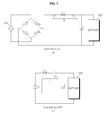
- FIGS. 6 and 7 are views referred to for describing operation of the circuit of FIG. 5 .
- FIG. 6 shows the case in which the equivalent circuit of the driving unit 200 of FIG. 5 operates in the boost mode.
- FIG. 6(a) shows the case in which, when the switching element S 1 of the switching unit 410 and the a-phase lower-arm switching element S' a are turned on, a closed loop is formed by the switching element S 1 , the a-phase inductor L a , and the a-phase lower-arm switching element S' a such that current I 1 flows. Accordingly, energy is accumulated in the a-phase inductor L a based on current I 1 . At this time, the a-phase upper-arm switching element S a is turned off.
- FIG. 6(b) shows the case in which, when the switching element S 1 of the switching unit 410 and the a-phase upper-arm switching element S a are turned on, current I 2 flows through the a-phase upper-arm switching element S a .
- current I 2 the energy accumulated in the a-phase inductor L a in FIG. 6(a) is stored in the capacitor C and the battery 205.
- the boosted DC voltage is stored in the battery 205.
- the a-phase lower-arm switching element S' a is turned off.
- the switching element S 1 of the switching unit 410 is continuously turned on and the a-phase lower-arm switching element S' a is turned on/off, that is, operates in the PWM mode.
- FIG. 7 shows the case in which the equivalent circuit of the driving unit 200 of FIG. 5 operates in the buck mode.
- FIG. 7(a) shows the case in which, when the switching element S 1 of the switching unit 410 and the a-phase upper-arm switching element S a are turned on, current I 3 flows through the switching element S 1 and the a-phase upper-arm switching element S a .
- current I 3 the DC voltage is stored in the capacitor C and the battery 205.
- Energy is accumulated in the a-phase inductor L a based on current I 3 .
- the a-phase lower-arm switching element S' a is turned off.
- FIG. 7(b) shows the case in which the switching element S 1 of the switching unit 410 and the a-phase lower-arm switching element S' a are turned off, current I 4 flows through the diode D 1 , the a-phase inductor L a and the diode D sa connected to the a-phase upper-arm switching element S a in inverse parallel.
- energy is accumulated in the a-phase inductor L a based on current I 4 .
- the a-phase upper-arm switching element S a is turned off.
- the switching element S 1 of the switching unit 410 is turned on/off, that is, operates in the PWM mode, and the a-phase lower-arm switching element S' a is continuously turned off.
- the voltage boosting operation or the voltage drop operation of the driving unit 200 may be determined by comparison between the voltage across the capacitor C and the voltage across the capacitor C x provided at the output end of the rectifier 412.
- the controller 430 may control the switching elements S 1 , S a and S' a so as to perform the voltage boosting operation as shown in FIG. 6 when the voltage across the capacitor C x is less than the voltage across the capacitor C.
- the controller 430 may control the switching elements S 1 , S a and S' a so as to perform the voltage drop operation as shown in FIG. 6 when the voltage across the capacitor C x is greater than the voltage across the capacitor C.
- FIG. 8 is a block diagram showing the internal configuration of the controller of FIG. 3 .
- the controller 430 may include an axis transformation unit 510, a speed calculator 520, a current command generator 530, a voltage command generator 540, an axis transformation unit 550 and a switching control signal output unit 560.
- the axis transformation unit 510 receives and transforms three-phase output currents i a , i b and i c detected by the output current detector E into two-phase currents i ⁇ and i ⁇ of a stationary reference frame.
- the axis transformation unit 510 may transform two-phase currents i ⁇ and i ⁇ of the stationary reference frame into two-phase currents i d and iq of a rotating reference frame.
- the speed calculator 520 may calculate a speed ⁇ r based on the location signal H of the rotator received from the position sensor 235. That is, the speed calculator may calculate the speed by dividing the movement distance of the rotator by the time based on the location signal of the rotator.
- the position sensor 235 may sense the location of the rotator of the motor 250.
- the position sensor 235 may include a hall sensor.
- the speed calculator 520 may output the calculated location ⁇ r and the calculated speed ⁇ r , based on the received location signal H of the rotator.
- the current command generator 530 calculates a speed command value ⁇ * r based on the calculated speed ⁇ r and a target speed ⁇ and generates a current command value i* q based on the speed command value ⁇ * r .
- the current command generator 530 may perform PI control of the PI controller 535 based on the speed command value ⁇ * r which is the difference between the calculated speed ⁇ r and the target speed ⁇ and generate the current command value i* q .
- the q-axis current command value i* q is shown as the current command value in the figure, the d-axis current command value i* d may also be generated. Meanwhile, the value of the d-axis current command value i* d may be set to 0.
- the current command generator 530 may further include a limiter (not shown) for limiting the level of the current command value i* q such that the current command value i* q does not exceed an allowable range.
- the voltage command generator 540 generates d-axis and q-axis voltage command values v* d and v* q based on d-axis and q-axis currents i d and iq transformed to the two-phase rotating reference frame by the axis transformation unit and the current command values i* d and i* q of the current command generator 530.
- the voltage command generator 540 may perform PI control of the PI controller 544 and generate the q-axis voltage command value v* q , based on a difference between the q-axis current iq and the q-axis current command value i* q .
- the voltage command generator 540 may perform PI control of the PI controller 548 and generate the d-axis voltage command value v* d , based on a difference between the d-axis current i d and the d-axis current command value i* d .
- the d-axis voltage command value v* d may be set to 0 when the d-axis current command value i* d is set to 0.
- the voltage command generator 540 may further include a limiter (not shown) for limiting the level of the d-axis and q-axis voltage command values v* d and v* q such that the d-axis and q-axis voltage command values v* d and v* q do not exceed an allowable range.
- a limiter (not shown) for limiting the level of the d-axis and q-axis voltage command values v* d and v* q such that the d-axis and q-axis voltage command values v* d and v* q do not exceed an allowable range.
- the generated d-axis and q-axis voltage command values v* d and v* q are input to the axis transformation unit 550.
- the axis transformation unit 550 receives the location ⁇ r calculated by the speed calculator 520 and the d-axis and q-axis voltage command values v* d and v* q and performs axis transformation.
- the axis transformation unit 550 transforms the two-phase rotating reference frame into the two-phase stationary reference frame.
- the location ⁇ r calculated by the speed calculator 520 may be used.
- the axis transformation unit 550 transforms the two-phase stationary reference frame into the three-phase stationary reference frame. Through such transformation, the axis transformation unit 550 outputs three-phase voltage command values v* a , v* b and v* c .
- the switching control signal output unit 560 generates and outputs an inverter switching control signal S ic according to the pulse width modulation (PWM) method based on the three-phase output voltage command values v* a , v* b and v* c .
- PWM pulse width modulation
- the output inverter switching control signal S ic may be converted into a gate driving signal by a gate driving unit (not shown) and may be input to the gates of the switching elements of the inverter 420.
- a gate driving unit not shown
- the switching elements S a , S'a, S b , S' b , S c and S' c of the inverter 420 perform the switching operation.
- the controller 430 may control the switching operation of the switching element S 1 of the switching unit 410.
- the two-phase switching elements among the three-phase switching elements of the inverter operate. That is, the PWM signal is applied to the coils wound on the stators of two phases among the three phases of the motor 250.
- the controller 430 may sense the location of the rotator and output the switching control signal S ic such that the location of the rotator is maintained. That is, the PWM signals are applied to the coil wound on the stator of the a-phase and the coil wound on the stator of the c-phase among the three phases of the motor 250 such that the location of the rotator 135 is maintained.
- the rotator 135 is located between the a-phase stator and the c-phase stator and is separated from the a-phase stator by a predetermined angle ⁇ k.
- the controller 430 estimates the location of the stator based on the location signal H sensed by the position sensor 235 of FIG. 8 or estimates the location of the rotator and maintains the rotator 135 at the estimated location based on the output current i o sensed by the output current detector E.
- the rotator 135 is aligned between the a-phase stator and the c-phase stator.
- the controller 430 may control operation of only the a-phase upper-arm and lower-arm switching elements S a and S' a and the c-phase upper-arm and lower-arm switching elements S c and S' c of the total of the three pairs of switching elements S a , S' a , S b , S' b , S c and S' c of the inverter 420.
- the driving unit 200 that is, the charging apparatus 200, may be configured by the equivalent circuit shown in FIG. 10 .
- the torque command component of the current command component may not be generated such that torque is not generated.
- the current command generator 530 generates current command values i* d and i* q .
- the d-axis current command value i* d is a flux current command value
- the q-axis current command value i* q is a torque current command value
- the q-axis current command value i* q is set to 0 such that torque is not generated upon motor alignment. Accordingly, in the charging mode, upon rotator alignment, torque is not generated. Thus, the electric vehicle does not move.
- FIG. 9 is a diagram showing a relationship between current vector components of two phases of a stator applied to a motor and a flux vector of a rotator.
- a sum I total of the current vectors I a and I b of the two phases of the stators and the direction of a flux vector ⁇ example of the rotator may match. Further, the sum of the current vectors of the two phases of the stators and the flux vector of the rotator may match.
- FIG. 10 is a diagram showing another example of an equivalent circuit of the driving unit of FIG. 2 .
- the motor 250 may be expressed by the a-phase inductor L a and the c-phase inductor L c and the inverter 420 may be expressed by the a-phase switching elements S a and S' a and the c-phase switching elements S c and S' c in the circuit of the driving unit 200.
- the driving unit 200 may include the switching unit 410, inductors L a and L b , the a-phase switching elements S a and S' a , the c-phase switching elements S c and S' c and the capacitor C.
- the a-phase inductor L a and the c-phase inductor L c are connected in parallel and the a-phase switching elements S a and S' a and the c-phase switching elements S c and S' c are connected in parallel.
- the equivalent circuit of FIG. 10 may be referred to as a buck boost converter, because the switching unit 410, the inductor L a , the a-phase switching elements S a and S' a may operate in the boost mode as a boost converter and the switching unit 410, the inductor L a , the a-phase switching elements S a and S' a may operate in a buck mode as a buck converter.
- the switching unit 410, the inductor L c , the c-phase switching elements S c and S' c may operate in the boost mode as a boost converter and the switching unit 410, the inductor L c , the c-phase switching elements S c and S' c may operate in a buck mode as a buck converter.
- the equivalent circuit of FIG. 10 may be referred to as an interleaved buck boost converter, because a plurality of buck boost converters is connected in parallel.
- a cascade buck boost converter may perform an interleaving operation, in the embodiment of the present invention, since the rotator 135 is aligned between the a-phase stator and the c-phase stator, the interleaving operation may not be performed.
- each buck boost converter may perform the same operation.
- the buck boost converter composed of the switching unit 410, the inductor L a , and the a-phase switching elements S a and S' a will be focused upon.
- FIGS. 11 and 12 are views referred to for describing operation of the circuit of FIG. 10 .
- FIG. 11 shows the case in which the equivalent circuit of the driving unit 200 of FIG. 10 operates in the boost mode.
- FIG. 11(a) shows the case in which, when the switching element S 1 of the switching unit 410 and the a-phase lower-arm switching element S' a are turned on, a closed loop is formed by the switching element S 1 , the a-phase inductor L a , and the a-phase lower-arm switching element S' a such that current I 1 flows. Accordingly, energy is accumulated in the a-phase inductor L a based on current I 1 . At this time, the a-phase upper-arm switching element S a is turned off.
- FIG. 11(b) shows the case in which, when the switching element S 1 of the switching unit 410 and the a-phase upper-arm switching element S a are turned on, current I 2 flows through the a-phase upper-arm switching element S a .
- current I 2 the energy accumulated in the a-phase inductor L a in FIG. 11(a) is stored in the capacitor C and the battery 205.
- the boosted DC voltage is stored in the battery 205.
- the a-phase lower-arm switching element S' a is turned off.
- the switching element S 1 of the switching unit 410 is continuously turned on and the a-phase lower-arm switching element S' a is turned on/off, that is, operates in the PWM mode.
- FIG. 12 shows the case in which the equivalent circuit of the driving unit 200 of FIG. 10 operates in the buck mode.
- FIG. 12(a) shows the case in which, when the switching element S 1 of the switching unit 410 and the a-phase upper-arm switching element S a are turned on, current I 3 flows through the switching element S 1 and the a-phase upper-arm switching element S a .
- current I 3 the DC voltage is stored in the capacitor C and the battery 205.
- Energy is accumulated in the a-phase inductor L a based on current I 3 .
- the a-phase lower-arm switching element S' a is turned off.
- FIG. 12(b) shows the case in which the switching element S 1 of the switching unit 410 and the a-phase lower-arm switching element S' a are turned off, current I 4 flows through the diode D 1 , the a-phase inductor L a and the diode D sa connected to the a-phase upper-arm switching element S a in inverse parallel.
- energy is accumulated in the a-phase inductor L a based on current I 1 .
- the a-phase upper-arm switching element S a is turned off.
- the switching element S 1 of the switching unit 410 is turned on/off, that is, operates in the PWM mode, and the a-phase lower-arm switching element S' a is continuously turned off.
- the voltage boosting operation or the voltage drop operation of the driving unit 200 may be determined by comparison between the voltage across the capacitor C and the voltage across the capacitor C x provided at the output end of the rectifier 412.
- the controller 430 may control the switching elements S 1 , S a and S' a so as to perform the voltage boosting operation as shown in FIG. 11 when the voltage across the capacitor C x is less than the voltage across the capacitor C.
- the controller 430 may control the switching elements S 1 , S a and S' a so as to perform the voltage drop operation as shown in FIG. 11 when the voltage across the capacitor C x is greater than the voltage across the capacitor C.
- the switching elements of one phase of three-phase switching elements of the inverter operate to convert the input AC voltage into the DC voltage through the switching unit, the motor and the inverter and to supply the DC voltage to the battery. Accordingly, it is possible to easily perform charging using the AC voltage.
- the converter may include the switching unit, the motor and the inverter.
- the switching unit, the motor, and the inverter may operate as a boost converter and the switching unit, the motor, and the inverter may operate as a buck converter by operation of the switching elements of one phase of the three-phase switching elements of the inverter.
- the charging apparatus may operate as a buck boost converter. Therefore, the converter may adaptively perform a voltage boosting operation or a voltage drop operation according to the battery charging voltage.
- the buck boost converter may operate using only the switching unit. Therefore, it is possible to reduce costs.
- the inverter, the controller and the switching unit of the charging apparatus are implemented on the same circuit board, it is possible to implement a small-size charging apparatus.
- the switching elements of two phases of three-phase switching elements of the inverter operate to convert the input AC voltage into the DC voltage through the switching unit, the motor and the inverter and to supply the DC voltage to the battery. Accordingly, it is possible to easily perform charging using the AC voltage.
- the converter may include the switching unit, the motor and the inverter.
- the switching unit, the motor, and the inverter may operate as a boost converter and the switching unit, the motor, and the inverter may operate as a buck converter by operation of the switching elements of two phases of the three-phase switching elements of the inverter.
- the charging apparatus may operate as a buck boost converter. Therefore, the converter may adaptively perform a voltage boosting operation or a voltage drop operation according to the battery charging voltage.
- the method for operating the charging apparatus may be implemented as code that can be written to a processor-readable recording medium included in the charging apparatus and can thus be read by a processor.
- the processor-readable recording medium may be any type of recording device in which data can be stored in a processor-readable manner.
Landscapes
- Engineering & Computer Science (AREA)
- Power Engineering (AREA)
- Transportation (AREA)
- Mechanical Engineering (AREA)
- Electric Propulsion And Braking For Vehicles (AREA)
- Inverter Devices (AREA)
- Charge And Discharge Circuits For Batteries Or The Like (AREA)
Abstract
Description
- This application claims the priority benefit of Korean Patent Application Nos.
10-2013-0013517 10-2013-0013519, filed on February 6, 2013 - The present invention relates to a charging apparatus and an electric vehicle including the same, and more particularly to a charging apparatus for easily performing charging using an alternating current (AC) voltage and an electric vehicle including the same.
- A vehicle appeared by development of an internal combustion engine is a necessity but leads to environmental pollution or exhaustion of energy due to consumption of huge amounts of energy. Instead of a vehicle using an internal combustion engine as a power source, an electric vehicle using electricity as a power source and a hybrid vehicle using an internal combustion engine and electricity have been developed and used.
- Such an electric vehicle or hybrid vehicle generates output using a motor and a battery and various attempts to improve output and mileage are ongoing.
- Therefore, the present invention has been made in view of the above problems, and it is an object of the present invention to provide a charging apparatus for easily performing charging using an alternating current (AC) voltage and an electric vehicle including the same. Further, it is an object to provide a method for operating a charging apparatus during a charging mode.
- In accordance with an aspect of the present invention, the above and other objects can be accomplished by the provision of a charging apparatus including a converter for converting an input alternating current (AC) voltage into a direct current (DC) voltage in a charging mode, and a controller for controlling the converter, wherein the converter includes a motor, a switching unit for supplying the input AC voltage to the motor by a switching operation, and an inverter for operating switching elements of at least one phase of the three-phase switching elements and converting the voltage received from the motor into a predetermined DC voltage in the charging mode.
- In accordance with another aspect of the present invention, there is provided an electric vehicle including a battery, and a charging apparatus including a converter for converting an input alternating current (AC) voltage into a direct current (DC) voltage in a charging mode and a controller for controlling the converter, wherein the converter includes a motor, a switching unit for supplying the input AC voltage to the motor by a switching operation, and an inverter for operating switching elements of at least one phase of the three-phase switching elements and converting the voltage received from the motor into a predetermined DC voltage in the charging mode.
- Preferably, in the charging mode, a switching element of the switching unit, the motor and the switching elements of one phase of the inverter are adapted to operate in a buck mode or a boost mode.
- Preferably, in the charging mode, when a lower-arm switching element of the switching elements of one phase of the inverter is turned on and then turned off in a state in which a switching element of the switching unit is turned on, the switching element of the switching unit, the motor and the switching elements of one phase of the inverter are adapted to operate in a boost mode, and
when the switching element of the switching unit is turned on and then turned off in a state in which the lower-arm switching element of the switching elements of one phase of the inverter is turned off, the switching element of the switching unit, the motor and the switching elements of one phase of the inverter are adapted to operate in a buck mode. - Preferably, the inverter, the controller and the switching unit may be formed on the same circuit board.
- Preferably, in the charging mode, the controller is adapted to control the switching elements of one phase of the three-phase switching elements of the inverter such that a rotator of the motor is aligned with a predetermined location, and to control output of a switching control signal to the switching elements of one phase such that a torque command component of a current command component is not generated.
- Preferably, in the charging mode, the controller is adapted to sense the location of the rotator of the motor and to control the switching elements of a nearest phase of the three-phase switching elements of the inverter such that the rotator is located in correspondence with the nearest phase of the three phases of the stator of the motor.
- Preferably, the controller includes at least one of: a speed calculator for calculating rotator speed information of the motor based on a location signal of a rotator of the motor or detected current flowing in the motor; a current command generator for generating a current command value based on the speed information and a speed command value; a voltage command generator for generating a voltage command value based on the current command value and the detected current; and a switching control signal output unit for outputting a switching control signal for driving the inverter based on the voltage command value.
- Preferably, in the charging mode, a switching element of the switching unit, the motor and the switching elements of two phases of the inverter are adapted to operate in a buck mode or a boost mode.
- Preferably, in the charging mode, when a lower-arm switching element of the switching elements of two phases of the inverter is turned on and then turned off in a state in which a switching element of the switching unit is turned on, the switching element of the switching unit, the motor and the switching elements of two phases of the inverter are adapted to operate in a boost mode, and when the switching element of the switching unit is turned on and then turned off in a state in which the lower-arm switching element of the switching elements of two phases of the inverter is turned off, the switching element of the switching unit, the motor and the switching elements of two phases of the inverter are adapted to operate in a buck mode.
- Preferably, in the charging mode, the controller is adapted to control the switching elements of two phases of the three-phase switching elements of the inverter such that a rotator of the motor is aligned with a predetermined location and to control output of a switching control signal to the switching elements of two phases such that a torque command component of a current command component is not generated.
- Preferably, in the charging mode, the controller is adapted to sense a location of a rotator of the motor and to control the switching elements of two phases of the three-phase switching elements of the inverter such that the location of the rotator is maintained.
- Preferably, in the charging mode, the controller is adapted to control the switching elements of two phases of the three-phase switching elements of the inverter such that a rotator of the motor is aligned with a predetermined location and to control matching of a sum of current vectors applied to two phases of a stator of the motor and a direction of a flux vector of the rotator of the motor.
- Preferably, the inverter is adapted to convert a DC voltage from a battery into an AC voltage by a switching operation of three-phase switching elements and to drive the motor in a motor operation mode.
- The object is also solved by a method for operating a charging apparatus comprising a converter and a controller for controlling the converter, the converter includes a motor, a switching unit and an inverter having the three-phase switching elements, comprising in the charging mode the steps of: supplying the input AC voltage to the motor by a switching operation of the switching unit, controlling by the controller the operating of switching elements of at least one phase of the three-phase switching elements of the inverter, and converting the voltage received from the motor into a predetermined DC voltage for being supplied to a battery.
- The above and other objects, features and other advantages of the present invention will be more clearly understood from the following detailed description taken in conjunction with the accompanying drawings, in which:
-
FIG. 1 is a schematic diagram showing the body of an electric vehicle according to one embodiment of the present invention; -
FIG. 2 is a block diagram showing the internal configuration of a driving unit ofFIG. 1 ; -
FIG. 3 is a circuit diagram of the driving unit ofFIG. 2 ; -
FIG. 4 is a diagram showing the structure of a motor ofFIG. 2 ; -
FIG. 5 is a diagram showing an example of an equivalent circuit of the driving unit ofFIG. 2 ; -
FIGS. 6 and7 are views referred to for describing operation of the circuit ofFIG. 5 ; -
FIG. 8 is a block diagram showing the internal configuration of a controller ofFIG. 2 ; -
FIG. 9 is a diagram showing a relationship between current vector components of two phases of a stator applied to a motor and a flux vector of a rotator; -
FIG. 10 is a diagram showing another example of an equivalent circuit of the driving unit ofFIG. 2 ; and -
FIGS. 11 and12 are views referred to for describing operation of the circuit ofFIG. 10 . - Exemplary embodiments of the present invention will be described in detail with reference to the attached drawings.
- The terms "module" and "unit" attached to describe the names of components are used herein to aid in the understanding of the components and thus they should not be considered as having specific meanings or roles. Accordingly, the terms "module" and "unit" may be used interchangeably.
-
FIG. 1 is a schematic diagram showing the body of an electric vehicle according to one embodiment of the present invention. - Referring to
FIG. 1 , theelectric vehicle 100 according to one embodiment of the present invention may include abattery 205 for supplying a voltage, amotor driving unit 200 for receiving a voltage from thebattery 205 and driving amotor 250, themotor 250 rotated by themotor driving unit 200,front wheels 150 andrear wheels 155 rotated by themotor 250, front-wheel and rear-wheel suspensions motor 250 according to a gear ratio. - The
battery 205 supplies a voltage to themotor driving unit 200. In particular, the battery supplies a direct current (DC) voltage to a capacitor C of themotor driving unit 200. - The
battery 205 may be formed of a set of a plurality of unit cells. The plurality of unit cells may be managed by a battery management system (BMS) in order to maintain a constant voltage. That is, the plurality of unit cells may output a constant voltage by the BMS. - For example, the BMS may detect a voltage Vbat of the
battery 205 and send the voltage Vbat to an electronic controller (not shown) and/or acontroller 430 of themotor driving unit 200. When the voltage Vbat of the battery is decreased to a lower limit value or less, the BMS may supply the DC voltage stored in the capacitor C of themotor driving unit 200 to thebattery 205. In addition, when the voltage Vbat of the battery is increased to an upper limit value or more, the BMS may supply a DC voltage to the capacitor C of themotor driving unit 200. - The
battery 205 is preferably composed of a secondary battery for charging or discharging but the present invention is not limited thereto. - The
motor driving unit 200 receives a DC voltage from thebattery 205 via apower input cable 120 in a motor operation mode. Themotor driving unit 200 converts the DC voltage received from thebattery 205 into an alternating current (AC) voltage and supplies the AC voltage to themotor 250. The converted AC voltage may be a three-phase AC voltage. - The
motor driving unit 200 supplies the three-phase AC voltage to themotor 250 via a three-phase output cable 125 included in themotor driving unit 200 in the motor operation mode. Although themotor driving unit 200 ofFIG. 1 is shown as having the three-phase output cable 125 composed of three cables, three cables may be included in a single cable. - The
motor driving unit 200 may receive an input AC voltage, e.g. from an external power supply, convert the input AC voltage into a DC voltage, and supply the DC voltage to thebattery 205, in a charging mode. Thus, themotor driving unit 200 may be referred to as a charging apparatus. - In the present specification, the terms "motor driving unit" 200 and the "charging apparatus" are used interchangeably and have the same meaning.
- The
motor driving unit 200 according to the embodiment of the present invention will be described below with reference toFIG. 2 and subsequent figures thereof. - The
motor 250 includes astator 130 and arotator 135. Themotor 250 includes aninput cable 125 and receives an AC voltage from themotor driving unit 200. Themotor 250 may be a three-phase motor, for example. When a variable voltage/variable frequency AC voltage of each phase is applied to a coil of thestator 130 of each phase, the rotation speed of therotator 135 is changed according to applied frequency. - The
motor 250 may be any one of various motors such as an induction motor, a brushless DC motor (BLDC), a reluctance motor, etc. - The driving gear (not shown) may be provided on one side of the
motor 250. The driving gear converts rotation energy of themotor 250 according to gear ratio. The rotation energy output from the driving gear is delivered to thefront wheels 150 and/or therear wheels 155 to move theelectric vehicle 100. - The front-
wheel suspension 160 and the rear-wheel suspension 165 support thefront wheels 150 and therear wheels 155, respectively. The front-wheel suspension 160 and the rear-wheel suspension 165 support the wheels by a spring and/or a damper in a vertical direction such that vibrations of the road do not reach the vehicle body. - The
front wheels 150 may include a steering apparatus (not shown). The steering apparatus steers thefront wheels 150 such that a driver steers theelectric vehicle 100 in a desired direction. - Although not shown, the
electric vehicle 100 may include an electronic controller for controlling the electric vehicle, in particular electronic apparatuses included in the electric vehicle. The electronic controller (not shown) controls operation of each apparatus and may display information of the operation and/or status of each apparatus. In addition, the electronic controller may control the BMS and/or interact with an internal controller of the BMS. - The electronic controller (not shown) may generate a driving command value according to various driving modes (forward mode, backward mode, neutral mode and parking mode), based on sensed signals from at least one of an inclination angle sensor (not shown) for sensing an inclination angle of the
electric vehicle 100, a speed sensor (not shown) for sensing the speed of theelectric vehicle 100, a brake sensor (not shown) according to operation of a brake pedal and/or an accelerator sensor (not shown) according to operation of an accelerator pedal. At this time, the driving command value may be a torque command value or a speed command value, for example. - The
electric vehicle 100 according to the embodiment of the present invention may include an electric vehicle using a battery and a motor and a hybrid electric vehicle using a battery and a motor while using a combustion engine. At this time, the hybrid electric vehicle may further include a switch for selecting any one of the battery and the combustion engine and a transmission. A method for driving the hybrid electric vehicle may be divided into a serial method for converting mechanical energy output from the combustion engine into electric energy to drive the motor and a parallel method for simultaneously utilizing mechanical energy output from the combustion engine and electric energy of the battery. -
FIG. 2 is a block diagram showing the internal configuration of a driving unit ofFIG. 1 , andFIG. 3 is a circuit diagram of the driving unit ofFIG. 2 . - The
motor driving unit 200 according to the embodiment of the present invention, that is, the chargingapparatus 200, may include aconverter 405 and acontroller 430. Theconverter 405 may include aswitching unit 410, amotor 250, aninverter 420 and a DC/DC converter 445. Here, the DC/DC converter 445 may be selectively included. - The
switching unit 410 is provided at a front stage of themotor 250 and includes a switching element S1 to supply a voltage from an inputAC power source 201 to themotor 250 by a switching operation of the switching element. - Although the input
AC power source 201 is a single-phase AC power source inFIG. 2 , the input AC power source may be a three-phase AC power source. - A rectifier (412 of
FIG. 3 ) for rectifying the voltage from the inputAC power source 201 may be further provided at a front stage of theswitching unit 410. - In
FIG. 3 , as therectifier 412 of the single-phase AC voltage, four diodes Da, Db, Dc and Dd are used in the form of a bridge. However, any kind of rectifier could be used for rectifying one phase or three phase AC current. - The
switching unit 410 may include a switching element S1 for switching the voltage output from therectifier 412 and delivering the voltage to themotor 250 and a diode D1 provided between the switching element S1 and themotor 250. A capacitor Cx for smoothing the rectified voltage may be further provided between the switchingunit 410 and therectifier 412. - The
switching unit 410 according to the embodiment of the present invention may operate as a buck converter along with themotor 250. A general buck converter includes an inductor. However, according to the embodiment of the present invention, theswitching unit 410 does not include an inductor and uses a coil wound on thestator 130 of themotor 250 as an inductor. -
FIG. 3 shows an equivalent circuit of themotor 250. The three-phase motor 250 may be electrically expressed by an a-phase inductor La, a b-phase inductor Lb and a c-phase inductor Lc. - Assume that the
switching unit 410 according to the embodiment of the present invention operates as a buck converter. - The switching element S1 of the
switching unit 410 may be controlled by a switching control signal Scc of thecontroller 430. - Although not shown, an input current detector (not shown) may be provided between the
rectifier 412 and the inputAC power source 201. In addition, an input voltage detector (not shown) may be provided across a capacitor Cx of theswitching unit 410. - The input current detector (not shown) may detect input AC current received from the input
AC power source 201. As the input current detector (not shown), a current transformer (CT), a shunt resistor, etc. may be used. The detected input AC current may be input to thecontroller 430 as a discrete signal having a pulse shape. - The input voltage detector (not shown) may detect a voltage across the capacitor Cx. The input voltage detector may include a resistor, an amplifier, etc. The detected input voltage may be input to the
controller 430 as a discrete signal having a pulse shape. - The
inverter 420 includes a plurality of inverter switching elements, which may convert a DC voltage Vdc smoothed by an on/off operation of the switching elements into three-phase AC voltages va, vb and vc having a predetermined frequency and output the three-phase AC voltages to the three-phase synchronization motor 250. - In the
inverter 420, upper-arm switching elements Sa, Sb and Sc and lower-arm switching elements S'a, S'b and S'c connected in series form respective pairs and a total of three pairs of upper-arm and lower-arm switching elements Sa&S'a Sb&S'b and Sc&S'c are connected in parallel. The switching elements Sa, S'a, Sb, S'b, Sc and S'c are connected with diodes in inverse parallel. - The switching elements of the
inverter 420 perform the on/off operation based on an inverter switching control signal Sic from thecontroller 430. - The
inverter 420 converts the DC voltage from thebattery 205 to the AC voltage and drives themotor 250 in the motor operation mode of themotor 250. - In the
inverter 420 according to the embodiment of the present invention, one-phase switching elements among the three-phase switching elements of theinverter 420 operate in a charging mode. That is, any one pair of upper-arm and lower-arm switching elements among the three pairs of upper-arm and lower-arm switching elements may operate in the charging mode. - Accordingly, in the charging mode, the voltage from the input
AC power source 201 may be converted into the DC voltage via theswitching unit 410, themotor 250 and theinverter 420 and may be supplied to thebattery 205, which will be described below with reference toFIG. 4 and the subsequent figures. - The
controller 430 may control the operation of the switching elements of theinverter 420. Thecontroller 430 may receive output current io detected by the output current detector (E ofFIG. 8 ). - The
controller 430 outputs the inverter switching control signal Sic to theinverter 420 in order to control the switching operation of theinverter 420. The inverter switching control signal Sic is a pulse width modulation (PWM) switching control signal and is generated and output based on the output current value io detected by the output current detector E. - The
controller 430 may control the switching operation of the switching element S1 of theswitching unit 410. Thecontroller 430 may receive input current detected by the input current detector (not shown). Thecontroller 430 may output the converter switching control signal Scc to theswitching unit 410 in order to control the switching operation of theswitching unit 410. The converter switching control signal Scc is a pulse width modulation (PWM) switching control signal and is generated and output based on the input current detected by the input current detector (not shown). - The output current detector (E of
FIG. 8 ) may detect output current io flowing between theinverter 420 and the three-phase motor 250, that is, current flowing in themotor 250. The output current detector E may detect output currents ia, ib and ic of respective phases or detect output currents of two phases using ternary phase equilibrium. - The output current detector E may be provided between the
inverter 420 and themotor 250. For current detection, a current transformer (CT), a shunt resistor, etc. may be used. - When shunt resistors are used, three shunt resistors may be provided between the
inverter 420 and thesynchronization motor 250 or one end of each of the three shunt resistors may be connected to each of the three lower-arm switching elements, S'a, S'b and S'c of theinverter 420. Alternatively, two shunt resistors may be used using ternary phase equilibrium. When one shunt resistor is used, the shunt resistor may be provided between the capacitor C and theinverter 420. - The detected output current io is a discrete signal having a pulse shape and may be applied to the
controller 430. Based on the detected output current io, the inverter switching control signal Sic is generated. Hereinafter, assume that the detected output current io is three-phase output currents ia, ib and ic. - The DC/
DC converter 445 may be a bi-directional converter. That is, in the motor driving mode, the level of the DC voltage stored in thebattery 205 is changed and the level-changed DC voltage is output to theinverter 420. In the charging mode, the level of the generated DC voltage may be changed and the level-changed DC voltage may be sent to thebattery 205. - The DC/
DC converter 445 may not be included in thedriving unit 200. - The capacitor C for storing the DC voltage may be provided between the
inverter 420 and thebattery 205. The capacitor C may serve as a smoothing capacitor and the smoothing capacitor C may smooth the input voltage and store the smoothed voltage. - Although one smoothing capacitor C is shown in the figure, a plurality of capacitors may be included for stability.
- In
FIG. 3 , the capacitor C is provided between theinverter 420 and the DC/DC converter 445. - Both ends of the capacitor C may be referred to as DC ends or DC link ends, because a DC voltage is stored.
- The driving
unit 200 may further include a DC end voltage detector (not shown) for detecting the voltage between both ends of the capacitor C. - The DC end voltage detector (not shown) may detect a DC end voltage Vdc between both ends of the smoothing capacitor C. The DC end voltage detector B may include a resistor, an amplifier, etc. The detected DC end voltage Vdc may be a discrete signal having a pulse shape and may be input to the
controller 430. - When the DC/
DC converter 445 is not provided between theinverter 420 and thebattery 205, the DC end voltage Vdc detected by the DC end voltage detector (not shown) may correspond to the voltage VBAT of thebattery 205. - The
controller 430 may determine voltage boosting or voltage drop in the charging mode using the DC end voltage Vdc and/or the input voltage corresponding to the voltage VBAT of thebattery 205. - The
switching unit 410, theinverter 420 and thecontroller 430 are included in thedriving unit 200, that is, the chargingapparatus 200, and may be particularly formed on the same circuit board. Such a charging apparatus may be referred to as an on board charger (OBC). The inverter, the controller and the switching unit of the charging apparatus are provided on the same circuit board, thereby implementing a small-size charging apparatus. - In addition, in addition to the
switching unit 410, theinverter 420 and thecontroller 430, the DC/DC converter 445 may be included in thedriving unit 200, that is, the chargingapparatus 200, and may be particularly formed on the same circuit board. -
FIG. 4 is a diagram showing the structure of the motor ofFIG. 2 . - Referring to
FIG. 4 , themotor 250 is a three-phase AC motor, in which PWM signals are input to coils wound on a stator of an a-phase, a b-phase and a c-phase. Arotator 135 rotates by an electric field and a magnetic field. - The motor structure of
FIG. 4 is merely an example of the present invention and may be variously modified. - According to the embodiment of the present invention, in the charging mode for charging the
battery 205 with the input AC voltage, one-phase switching elements among the three-phase switching elements of the inverter operate. That is, the PWM signal is only applied to the coil wound on the stator of any one phase of the three phases of themotor 250. - For example, in the charging mode, as shown in
FIG. 4 , when therotator 135 is located near the a-phase, thecontroller 430 may sense the location of therotator 135 and output the switching control signal Sic such that therotator 135 is aligned with the a-phase. That is, the PWM signal is only applied to the coil wound on the stator of the a-phase among the three phases of themotor 250 such that therotator 135 is aligned with the a-phase. - In
FIG. 4 , the a-phase stator is separated from therotator 135 by a predetermined angle θk. Thecontroller 430 estimates the location of therotator 135 based on a location signal H sensed by thelocator sensor 235 ofFIG. 8 , estimates the location of therotator 135 based on the output current io sensed by the output current detector E and controls therotator 135 to be aligned with a closest phase of the three phases of thestator 130 of the motor. - In
FIG. 4 , since therotator 135 is located near the a-phase, therotator 135 is aligned with the a-phase stator. Thecontroller 430 may control only the a-phase upper-arm and lower-arm switching elements Sa and S'a among the total of three pairs of the upper-arm and lower-arm switching elements Sa, S'a, Sb, S'b, Sc and S'c of theinverter 420. - Thus, the driving
unit 200, that is, the chargingapparatus 200, may be configured by the equivalent circuit shown inFIG. 5 . - Upon motor rotator alignment, a torque command component of a current command component may not be generated such that torque is not generated. Referring to
FIG. 8 , acurrent command generator 530 generates current command values i*d and i*q. At this time, since the d-axis current command value i*d is a flux current command value and the q-axis current command value i*q is a torque current command value, in the embodiment of the present invention, the q-axis current command value i*q is set to 0 such that torque is not generated upon motor alignment. Accordingly, in the charging mode, upon rotator alignment, torque is not generated, thereby minimizing motion of the electric vehicle. -
FIG. 5 is a diagram showing an example of an equivalent circuit of the driving unit ofFIG. 2 . - Referring to
FIG. 5 , in the charging mode, when therotator 135 is aligned with the a-phase stator, themotor 250 is expressed by the a-phase inductor La and theinverter 420 is expressed by the a-phase switching elements Sa and S'a in the circuit of thedriving unit 200. - That is, the driving
unit 200 may include theswitching unit 410, the inductor La, the a-phase switching elements Sa and S'a and the capacitor C. - The equivalent circuit of
FIG. 5 may be referred to as a buck boost converter, because theswitching unit 410, the inductor La, and the a-phase switching elements Sa and S'a may operate in the boost mode as a boost converter and theswitching unit 410, the inductor La, and the a-phase switching elements Sa and S'a may operate in a buck mode as a buck converter. -
FIGS. 6 and7 are views referred to for describing operation of the circuit ofFIG. 5 . - First,
FIG. 6 shows the case in which the equivalent circuit of thedriving unit 200 ofFIG. 5 operates in the boost mode. -
FIG. 6(a) shows the case in which, when the switching element S1 of theswitching unit 410 and the a-phase lower-arm switching element S'a are turned on, a closed loop is formed by the switching element S1, the a-phase inductor La, and the a-phase lower-arm switching element S'a such that current I1 flows. Accordingly, energy is accumulated in the a-phase inductor La based on current I1. At this time, the a-phase upper-arm switching element Sa is turned off. -
FIG. 6(b) shows the case in which, when the switching element S1 of theswitching unit 410 and the a-phase upper-arm switching element Sa are turned on, current I2 flows through the a-phase upper-arm switching element Sa. By current I2, the energy accumulated in the a-phase inductor La inFIG. 6(a) is stored in the capacitor C and thebattery 205. As a result, the boosted DC voltage is stored in thebattery 205. At this time, the a-phase lower-arm switching element S'a is turned off. - That is, in the boost mode shown in
FIG. 6 , the switching element S1 of theswitching unit 410 is continuously turned on and the a-phase lower-arm switching element S'a is turned on/off, that is, operates in the PWM mode. - Next,
FIG. 7 shows the case in which the equivalent circuit of thedriving unit 200 ofFIG. 5 operates in the buck mode. -
FIG. 7(a) shows the case in which, when the switching element S1 of theswitching unit 410 and the a-phase upper-arm switching element Sa are turned on, current I3 flows through the switching element S1 and the a-phase upper-arm switching element Sa. By current I3, the DC voltage is stored in the capacitor C and thebattery 205. Energy is accumulated in the a-phase inductor La based on current I3. At this time, the a-phase lower-arm switching element S'a is turned off. -
FIG. 7(b) shows the case in which the switching element S1 of theswitching unit 410 and the a-phase lower-arm switching element S'a are turned off, current I4 flows through the diode D1, the a-phase inductor La and the diode Dsa connected to the a-phase upper-arm switching element Sa in inverse parallel. In particular, energy is accumulated in the a-phase inductor La based on current I4. At this time, the a-phase upper-arm switching element Sa is turned off. - That is, in the buck mode shown in
FIG. 7 , the switching element S1 of theswitching unit 410 is turned on/off, that is, operates in the PWM mode, and the a-phase lower-arm switching element S'a is continuously turned off. - The voltage boosting operation or the voltage drop operation of the
driving unit 200, that is, the chargingapparatus 200, may be determined by comparison between the voltage across the capacitor C and the voltage across the capacitor Cx provided at the output end of therectifier 412. - The
controller 430 may control the switching elements S1, Sa and S'a so as to perform the voltage boosting operation as shown inFIG. 6 when the voltage across the capacitor Cx is less than the voltage across the capacitor C. - The
controller 430 may control the switching elements S1, Sa and S'a so as to perform the voltage drop operation as shown inFIG. 6 when the voltage across the capacitor Cx is greater than the voltage across the capacitor C. -
FIG. 8 is a block diagram showing the internal configuration of the controller ofFIG. 3 . - Referring to
FIG. 8 , thecontroller 430 may include anaxis transformation unit 510, aspeed calculator 520, acurrent command generator 530, avoltage command generator 540, anaxis transformation unit 550 and a switching controlsignal output unit 560. - The
axis transformation unit 510 receives and transforms three-phase output currents ia, ib and ic detected by the output current detector E into two-phase currents iα and iβ of a stationary reference frame. - The
axis transformation unit 510 may transform two-phase currents iα and iβ of the stationary reference frame into two-phase currents id and iq of a rotating reference frame. - The
speed calculator 520 may calculate a speed ω̂ r based on the location signal H of the rotator received from theposition sensor 235. That is, the speed calculator may calculate the speed by dividing the movement distance of the rotator by the time based on the location signal of the rotator. - The
position sensor 235 may sense the location of the rotator of themotor 250. Theposition sensor 235 may include a hall sensor. - The
speed calculator 520 may output the calculated location θ̂r and the calculated speed ω̂ r , based on the received location signal H of the rotator. - The
current command generator 530 calculates a speed command value ω*r based on the calculated speed ω̂ r and a target speed ω and generates a current command value i*q based on the speed command value ω*r. For example, thecurrent command generator 530 may perform PI control of thePI controller 535 based on the speed command value ω*r which is the difference between the calculated speed ω̂ r and the target speed ω and generate the current command value i*q. Although the q-axis current command value i*q is shown as the current command value in the figure, the d-axis current command value i*d may also be generated. Meanwhile, the value of the d-axis current command value i*d may be set to 0. - The
current command generator 530 may further include a limiter (not shown) for limiting the level of the current command value i*q such that the current command value i*q does not exceed an allowable range. - Next, the
voltage command generator 540 generates d-axis and q-axis voltage command values v*d and v*q based on d-axis and q-axis currents id and iq transformed to the two-phase rotating reference frame by the axis transformation unit and the current command values i*d and i*q of thecurrent command generator 530. For example, thevoltage command generator 540 may perform PI control of thePI controller 544 and generate the q-axis voltage command value v*q, based on a difference between the q-axis current iq and the q-axis current command value i*q. In addition, thevoltage command generator 540 may perform PI control of thePI controller 548 and generate the d-axis voltage command value v*d, based on a difference between the d-axis current id and the d-axis current command value i*d. The d-axis voltage command value v*d may be set to 0 when the d-axis current command value i*d is set to 0. - The
voltage command generator 540 may further include a limiter (not shown) for limiting the level of the d-axis and q-axis voltage command values v*d and v*q such that the d-axis and q-axis voltage command values v*d and v*q do not exceed an allowable range. - The generated d-axis and q-axis voltage command values v*d and v*q are input to the
axis transformation unit 550. - The
axis transformation unit 550 receives the location θ̂r calculated by thespeed calculator 520 and the d-axis and q-axis voltage command values v*d and v*q and performs axis transformation. - First, the
axis transformation unit 550 transforms the two-phase rotating reference frame into the two-phase stationary reference frame. At this time, the location θ̂r calculated by thespeed calculator 520 may be used. - The
axis transformation unit 550 transforms the two-phase stationary reference frame into the three-phase stationary reference frame. Through such transformation, theaxis transformation unit 550 outputs three-phase voltage command values v*a, v*b and v*c. - The switching control
signal output unit 560 generates and outputs an inverter switching control signal Sic according to the pulse width modulation (PWM) method based on the three-phase output voltage command values v*a, v*b and v*c. - The output inverter switching control signal Sic may be converted into a gate driving signal by a gate driving unit (not shown) and may be input to the gates of the switching elements of the
inverter 420. Thus, the switching elements Sa, S'a, Sb, S'b, Sc and S'c of theinverter 420 perform the switching operation. - The
controller 430 may control the switching operation of the switching element S1 of theswitching unit 410. - According to another embodiment of the present invention, in the charging mode for charging the
battery 205 with the input AC voltage, the two-phase switching elements among the three-phase switching elements of the inverter operate. That is, the PWM signal is applied to the coils wound on the stators of two phases among the three phases of themotor 250. - For example, in the charging mode, as shown in
FIG. 4 , when therotator 135 is located between the a-phase stator and the c-phase stator, thecontroller 430 may sense the location of the rotator and output the switching control signal Sic such that the location of the rotator is maintained. That is, the PWM signals are applied to the coil wound on the stator of the a-phase and the coil wound on the stator of the c-phase among the three phases of themotor 250 such that the location of therotator 135 is maintained. - In the figure, the
rotator 135 is located between the a-phase stator and the c-phase stator and is separated from the a-phase stator by a predetermined angle θk. Thecontroller 430 estimates the location of the stator based on the location signal H sensed by theposition sensor 235 ofFIG. 8 or estimates the location of the rotator and maintains therotator 135 at the estimated location based on the output current io sensed by the output current detector E. - In
FIG. 4 , therotator 135 is aligned between the a-phase stator and the c-phase stator. Thecontroller 430 may control operation of only the a-phase upper-arm and lower-arm switching elements Sa and S'a and the c-phase upper-arm and lower-arm switching elements Sc and S'c of the total of the three pairs of switching elements Sa, S'a, Sb, S'b, Sc and S'c of theinverter 420. - The driving
unit 200, that is, the chargingapparatus 200, may be configured by the equivalent circuit shown inFIG. 10 . - Upon motor rotator alignment, the torque command component of the current command component may not be generated such that torque is not generated. Referring to
FIG. 8 , thecurrent command generator 530 generates current command values i*d and i*q. At this time, since the d-axis current command value i*d is a flux current command value and the q-axis current command value i*q is a torque current command value, in the embodiment of the present invention, the q-axis current command value i*q is set to 0 such that torque is not generated upon motor alignment. Accordingly, in the charging mode, upon rotator alignment, torque is not generated. Thus, the electric vehicle does not move. -
FIG. 9 is a diagram showing a relationship between current vector components of two phases of a stator applied to a motor and a flux vector of a rotator. - Referring to
FIG. 9 , as shown inFIG. 4 , in order to align therotator 135 between the a-phase stator and the c-phase stator, a sum Itotal of the current vectors Ia and Ib of the two phases of the stators and the direction of a flux vector ψexample of the rotator may match. Further, the sum of the current vectors of the two phases of the stators and the flux vector of the rotator may match. - Thus, the torque component of the rotator is not generated and thus the electric vehicle does not move upon rotator alignment in the charging mode.
-
FIG. 10 is a diagram showing another example of an equivalent circuit of the driving unit ofFIG. 2 . - Referring to
FIG. 10 , in the charging mode, when therotator 135 is aligned between the a-phase stator and the c-phase stator, themotor 250 may be expressed by the a-phase inductor La and the c-phase inductor Lc and theinverter 420 may be expressed by the a-phase switching elements Sa and S'a and the c-phase switching elements Sc and S'c in the circuit of thedriving unit 200. - That is, the driving
unit 200 may include theswitching unit 410, inductors La and Lb, the a-phase switching elements Sa and S'a, the c-phase switching elements Sc and S'c and the capacitor C. - At this time, the a-phase inductor La and the c-phase inductor Lc are connected in parallel and the a-phase switching elements Sa and S'a and the c-phase switching elements Sc and S'c are connected in parallel.
- The equivalent circuit of
FIG. 10 may be referred to as a buck boost converter, because theswitching unit 410, the inductor La, the a-phase switching elements Sa and S'a may operate in the boost mode as a boost converter and theswitching unit 410, the inductor La, the a-phase switching elements Sa and S'a may operate in a buck mode as a buck converter. - In addition, in the equivalent circuit of
FIG. 10 , theswitching unit 410, the inductor Lc, the c-phase switching elements Sc and S'c may operate in the boost mode as a boost converter and theswitching unit 410, the inductor Lc, the c-phase switching elements Sc and S'c may operate in a buck mode as a buck converter. - As a result, since the equivalent circuit of
FIG. 10 may be referred to as an interleaved buck boost converter, because a plurality of buck boost converters is connected in parallel. - Although a cascade buck boost converter may perform an interleaving operation, in the embodiment of the present invention, since the
rotator 135 is aligned between the a-phase stator and the c-phase stator, the interleaving operation may not be performed. For example, each buck boost converter may perform the same operation. - Hereinafter, the buck boost converter composed of the
switching unit 410, the inductor La, and the a-phase switching elements Sa and S'a will be focused upon. -
FIGS. 11 and12 are views referred to for describing operation of the circuit ofFIG. 10 . - First,
FIG. 11 shows the case in which the equivalent circuit of thedriving unit 200 ofFIG. 10 operates in the boost mode. -
FIG. 11(a) shows the case in which, when the switching element S1 of theswitching unit 410 and the a-phase lower-arm switching element S'a are turned on, a closed loop is formed by the switching element S1, the a-phase inductor La, and the a-phase lower-arm switching element S'a such that current I1 flows. Accordingly, energy is accumulated in the a-phase inductor La based on current I1. At this time, the a-phase upper-arm switching element Sa is turned off. -
FIG. 11(b) shows the case in which, when the switching element S1 of theswitching unit 410 and the a-phase upper-arm switching element Sa are turned on, current I2 flows through the a-phase upper-arm switching element Sa. By current I2, the energy accumulated in the a-phase inductor La inFIG. 11(a) is stored in the capacitor C and thebattery 205. As a result, the boosted DC voltage is stored in thebattery 205. At this time, the a-phase lower-arm switching element S'a is turned off. - That is, in the boost mode shown in
FIG. 11 , the switching element S1 of theswitching unit 410 is continuously turned on and the a-phase lower-arm switching element S'a is turned on/off, that is, operates in the PWM mode. - Next,
FIG. 12 shows the case in which the equivalent circuit of thedriving unit 200 ofFIG. 10 operates in the buck mode. -
FIG. 12(a) shows the case in which, when the switching element S1 of theswitching unit 410 and the a-phase upper-arm switching element Sa are turned on, current I3 flows through the switching element S1 and the a-phase upper-arm switching element Sa. By current I3, the DC voltage is stored in the capacitor C and thebattery 205. Energy is accumulated in the a-phase inductor La based on current I3. At this time, the a-phase lower-arm switching element S'a is turned off. -
FIG. 12(b) shows the case in which the switching element S1 of theswitching unit 410 and the a-phase lower-arm switching element S'a are turned off, current I4 flows through the diode D1, the a-phase inductor La and the diode Dsa connected to the a-phase upper-arm switching element Sa in inverse parallel. In particular, energy is accumulated in the a-phase inductor La based on current I1. At this time, the a-phase upper-arm switching element Sa is turned off. - That is, in the buck mode shown in
FIG. 12 , the switching element S1 of theswitching unit 410 is turned on/off, that is, operates in the PWM mode, and the a-phase lower-arm switching element S'a is continuously turned off. - The voltage boosting operation or the voltage drop operation of the
driving unit 200, that is, the chargingapparatus 200, may be determined by comparison between the voltage across the capacitor C and the voltage across the capacitor Cx provided at the output end of therectifier 412. - The
controller 430 may control the switching elements S1, Sa and S'a so as to perform the voltage boosting operation as shown inFIG. 11 when the voltage across the capacitor Cx is less than the voltage across the capacitor C. - The
controller 430 may control the switching elements S1, Sa and S'a so as to perform the voltage drop operation as shown inFIG. 11 when the voltage across the capacitor Cx is greater than the voltage across the capacitor C. - The charging apparatus and the electric vehicle including the same according to the foregoing embodiments are not restricted to the embodiments set forth herein. Therefore, variations and combinations of the exemplary embodiments set forth herein may fall within the scope of the present invention.
- According to one embodiment of the present invention, in the charging apparatus and the electric vehicle including the same, in the charging mode, the switching elements of one phase of three-phase switching elements of the inverter operate to convert the input AC voltage into the DC voltage through the switching unit, the motor and the inverter and to supply the DC voltage to the battery. Accordingly, it is possible to easily perform charging using the AC voltage.
- In particular, the converter may include the switching unit, the motor and the inverter. The switching unit, the motor, and the inverter may operate as a boost converter and the switching unit, the motor, and the inverter may operate as a buck converter by operation of the switching elements of one phase of the three-phase switching elements of the inverter. As a result, the charging apparatus may operate as a buck boost converter. Therefore, the converter may adaptively perform a voltage boosting operation or a voltage drop operation according to the battery charging voltage.
- Since the charging apparatus uses the motor and the inverter, the buck boost converter may operate using only the switching unit. Therefore, it is possible to reduce costs.
- In addition, since a capacitor having a high rated voltage is not used between the switching unit serving as the buck converter and the motor serving as the boost converter, it is possible to reduce costs.
- Upon initial charging, since the switching elements of one phase of the three-phase switching elements of the inverter operate after the location of the rotator of the motor is determined, it is possible to minimize movement of the rotator of the motor in the charging mode.
- Since the inverter, the controller and the switching unit of the charging apparatus are implemented on the same circuit board, it is possible to implement a small-size charging apparatus.
- According to another embodiment of the present invention, in the charging apparatus and the electric vehicle including the same, in the charging mode, the switching elements of two phases of three-phase switching elements of the inverter operate to convert the input AC voltage into the DC voltage through the switching unit, the motor and the inverter and to supply the DC voltage to the battery. Accordingly, it is possible to easily perform charging using the AC voltage.
- In particular, the converter may include the switching unit, the motor and the inverter. The switching unit, the motor, and the inverter may operate as a boost converter and the switching unit, the motor, and the inverter may operate as a buck converter by operation of the switching elements of two phases of the three-phase switching elements of the inverter. As a result, the charging apparatus may operate as a buck boost converter. Therefore, the converter may adaptively perform a voltage boosting operation or a voltage drop operation according to the battery charging voltage.
- Upon initial charging, since the switching elements of two phases of the three-phase switching elements of the inverter operate after the location of the rotator of the motor is determined, it is possible to perform charging in a state of stopping the rotator of the motor in the charging mode.
- The method for operating the charging apparatus according to the foregoing embodiments may be implemented as code that can be written to a processor-readable recording medium included in the charging apparatus and can thus be read by a processor. The processor-readable recording medium may be any type of recording device in which data can be stored in a processor-readable manner.
- Although the preferred embodiments of the present invention have been disclosed for illustrative purposes, those skilled in the art will appreciate that various modifications, additions and substitutions are possible, without departing from the scope of the invention as disclosed in the accompanying claims.
Claims (15)
- A charging apparatus comprising:a converter (405) for converting an input alternating current (AC) voltage into a direct current (DC) voltage in a charging mode; anda controller (430) for controlling the converter (405),wherein the converter (405) includes:a motor (250);a switching unit (410) for supplying the input AC voltage to the motor (250) by a switching operation; andan inverter (420) for operating switching elements Sa, Sa' of at least one phase of the three-phase switching elements and converting the voltage received from the motor (250) into a predetermined DC voltage in the charging mode.
- The charging apparatus according to claim 1, wherein, in the charging mode, a switching element (S1) of the switching unit (410), the motor (250) and the switching elements Sa, Sa' of one phase of the inverter (410) are adapted to operate in a buck mode or a boost mode.
- The charging apparatus according to any one of the preceding claims, wherein, in the charging mode,
when a lower-arm switching element (Sa') of the switching elements of one phase of the inverter (420) is turned on and then turned off in a state in which a switching element (S1) of the switching unit (410) is turned on, the switching element (S1) of the switching unit (410), the motor (250) and the switching elements (Sa, Sa') of one phase of the inverter (420) are adapted to operate in a boost mode, and
when the switching element (S1) of the switching unit (410) is turned on and then turned off in a state in which the lower-arm switching element (Sa') of the switching elements of one phase of the inverter (420) is turned off, the switching element (S1) of the switching unit (410), the motor (250) and the switching elements (Sa, Sa') of one phase of the inverter (420) are adapted to operate in a buck mode. - The charging apparatus according to any one of the preceding claims, wherein the inverter (420), the controller (430) and the switching unit (410) are formed on the same circuit board.
- The charging apparatus according to any one of the preceding claims, wherein, in the charging mode, the controller (430) is adapted to control the switching elements (Sa, Sa') of one phase of the three-phase switching elements of the inverter (420) such that a rotator (135) of the motor (250) is aligned with a predetermined location, and to control output of a switching control signal (Sic) to the switching elements (Sa, Sa') of one phase such that a torque command component of a current command component is not generated.
- The charging apparatus according to claim 5, wherein, in the charging mode, the controller (430) is adapted to sense the location of the rotator (135) of the motor (250) and to control the switching elements of a nearest phase of the three-phase switching elements of the inverter (420) such that the rotator (135) is located in correspondence with the nearest phase of the three phases of the stator (130) of the motor (250).
- The charging apparatus according to any one of the preceding claims, wherein the controller (430) includes at least one of :a speed calculator (520) for calculating rotator speed information of the motor (250) based on a location signal of a rotator (135) of the motor or detected current flowing in the motor (250);a current command generator (530) for generating a current command value based on the speed information and a speed command value;a voltage command generator (540) for generating a voltage command value based on the current command value and the detected current; anda switching control signal output unit (560) for outputting a switching control signal (Sic) for driving the inverter (420) based on the voltage command value.
- The charging apparatus according to claim 1, wherein, in the charging mode, a switching element (S1) of the switching unit (410), the motor (250) and the switching elements (Sa, Sa', Sc, Sc') of two phases of the inverter (420) are adapted to operate in a buck mode or a boost mode.
- The charging apparatus according to any one of claim 1 or 8, wherein, in the charging mode,
when a lower-arm switching element (Sa', Sc') of the switching elements of two phases of the inverter (420) is turned on and then turned off in a state in which a switching element (S1) of the switching unit (410) is turned on, the switching element (S1) of the switching unit (410), the motor (250) and the switching elements (Sa, Sa', Sc, Sc') of two phases of the inverter (420) are adapted to operate in a boost mode, and
when the switching element (S1) of the switching unit (410) is turned on and then turned off in a state in which the lower-arm switching element (Sa', Sc') of the switching elements of two phases of the inverter (420) is turned off, the switching element (S1) of the switching unit (410), the motor (250) and the switching elements (Sa, Sa', Sc, Sc') of two phases of the inverter (420) are adapted to operate in a buck mode. - The charging apparatus according to any one of claim 1, 8 or 9, wherein, in the charging mode, the controller (430) is adapted to control the switching elements (Sa, Sa', Sc, Sc') of two phases of the three-phase switching elements of the inverter (420) such that a rotator (135) of the motor (235) is aligned with a predetermined location and to control output of a switching control signal (Sic) to the switching elements (Sa, Sa', Sc, Sc') of two phases such that a torque command component of a current command component is not generated.
- The charging apparatus according to any one of claim 1, 8, 9 or 10, wherein, in the charging mode, the controller (430) is adapted to sense a location of a rotator (135) of the motor (250) and to control the switching elements (Sa, Sa', Sc, Sc') of two phases of the three-phase switching elements of the inverter (420) such that the location of the rotator (135) is maintained.
- The charging apparatus according to any one of claim 1, 8, 9, 10 or 11, wherein, in the charging mode, the controller (430) is adapted to control the switching elements (Sa, Sa', Sc, Sc') of two phases of the three-phase switching elements of the inverter (420) such that a rotator (135) of the motor (250) is aligned with a predetermined location and to control matching of a sum of current vectors applied to two phases of a stator (130) of the motor (250) and a direction of a flux vector of the rotator (135) of the motor (250).
- The charging apparatus according to any one of the preceding claims, wherein the inverter (420) is adapted to convert a DC voltage from a battery (205) into an AC voltage by a switching operation of three-phase switching elements and to drive the motor (250) in a motor operation mode.
- An electric vehicle comprising:a battery (205); anda charging apparatus (200) including a converter (405) for converting an input alternating current (AC) voltage into a direct current (DC) voltage in a charging mode and a controller (430) for controlling the converter (405), wherein the converter (405) includes:a motor (250);a switching unit (410) for supplying the input AC voltage to the motor (250) by a switching operation; andan inverter (420) for operating switching elements (Sa, Sa') of at least one phase of the three-phase switching elements and converting the voltage received from the motor (250) into a predetermined DC voltage in the charging mode.
- The electric vehicle of claim 14, wherein the inverter (420) is adapted to convert a DC voltage from a battery (205) into an AC voltage by a switching operation of three-phase switching elements and to drive the motor in a motor operation mode.
Applications Claiming Priority (2)
| Application Number | Priority Date | Filing Date | Title |
|---|---|---|---|
| KR1020130013519A KR101563866B1 (en) | 2013-02-06 | 2013-02-06 | charging apparatus and electric vehicle including the same |
| KR1020130013517A KR101563867B1 (en) | 2013-02-06 | 2013-02-06 | charging apparatus and electric vehicle including the same |
Publications (2)
| Publication Number | Publication Date |
|---|---|
| EP2765022A2 true EP2765022A2 (en) | 2014-08-13 |
| EP2765022A3 EP2765022A3 (en) | 2017-03-29 |
Family
ID=50033441
Family Applications (1)
| Application Number | Title | Priority Date | Filing Date |
|---|---|---|---|
| EP14154212.6A Withdrawn EP2765022A3 (en) | 2013-02-06 | 2014-02-06 | Charging apparatus and electric vehicle including the same |
Country Status (3)
| Country | Link |
|---|---|
| US (1) | US9376025B2 (en) |
| EP (1) | EP2765022A3 (en) |
| CN (1) | CN103972972B (en) |
Cited By (5)
| Publication number | Priority date | Publication date | Assignee | Title |
|---|---|---|---|---|
| EP3264577A1 (en) * | 2016-06-29 | 2018-01-03 | WABCO GmbH | Voltage regulator unit, vehicle controller and method for pre-regulating a supply voltage |
| WO2018142157A1 (en) * | 2017-02-03 | 2018-08-09 | Arm Limited | Motor driver and a method of operating thereof |
| US10056858B2 (en) | 2014-09-17 | 2018-08-21 | Arm Limited | Motor driver and a method of operating thereof |
| WO2018193266A1 (en) * | 2017-04-19 | 2018-10-25 | Sevcon Limited | Dc-dc converter |
| EP3904150A1 (en) * | 2020-04-28 | 2021-11-03 | Hyundai Motor Company | Charging system and method using motor driving system |
Families Citing this family (13)
| Publication number | Priority date | Publication date | Assignee | Title |
|---|---|---|---|---|
| KR101568225B1 (en) * | 2013-02-06 | 2016-07-20 | 엘지전자 주식회사 | charging apparatus and electric vehicle including the same |
| JP6301240B2 (en) * | 2014-02-07 | 2018-03-28 | 本田技研工業株式会社 | Battery charger for vehicle |
| US10693307B2 (en) | 2014-12-22 | 2020-06-23 | Volvo Truck Corporation | Three phase charger accommodating wide input voltage range with flexible single phase input options |
| EP3157162B1 (en) * | 2015-01-28 | 2020-07-15 | Panasonic Intellectual Property Management Co., Ltd. | Motor control device, and method for correcting torque constant in such motor control device |
| MX361850B (en) * | 2015-06-23 | 2018-12-18 | Nissan Motor | Inverter with charging capability. |
| KR20170137490A (en) * | 2016-06-03 | 2017-12-13 | 현대자동차주식회사 | Integrated Module of OBC and Inverter and the Controlling Method thereof |
| JP6489111B2 (en) * | 2016-12-20 | 2019-03-27 | トヨタ自動車株式会社 | Power system for electric vehicles |
| CN108347167B (en) * | 2017-01-25 | 2021-07-13 | 通用电气公司 | System and method for soft-switching DC-DC converters |
| JP6969342B2 (en) * | 2017-12-14 | 2021-11-24 | 株式会社デンソー | Motor drive |
| CN108809176B (en) * | 2018-06-22 | 2019-04-30 | 湖南科技大学 | A Control Method of Asynchronous Motor Speed Regulation System Based on Buck-Boost Matrix Converter |
| CN113300489B (en) * | 2021-06-02 | 2022-11-11 | 哈尔滨工业大学 | Rotary wireless electric energy transmission device and system based on three-phase semi-cylinder curved surface coil |
| US11824451B2 (en) * | 2021-08-13 | 2023-11-21 | Analog Devices, Inc. | Multi-phase buck-boost converter |
| CN117977991B (en) * | 2024-02-05 | 2024-12-03 | 格至达智能科技(江苏)有限公司 | Mode management method, device and computer storage medium for electric drive inverter |
Family Cites Families (33)
| Publication number | Priority date | Publication date | Assignee | Title |
|---|---|---|---|---|
| GB1604066A (en) * | 1978-05-26 | 1981-12-02 | Chloride Group Ltd | Battery charges in variable reluctance electric motor systems |
| JP3284571B2 (en) * | 1992-01-24 | 2002-05-20 | 株式会社明電舎 | Electric car |
| JP3692993B2 (en) * | 2001-10-04 | 2005-09-07 | トヨタ自動車株式会社 | DRIVE DEVICE AND POWER OUTPUT DEVICE |
| JP4438417B2 (en) * | 2004-01-13 | 2010-03-24 | トヨタ自動車株式会社 | AC voltage generator and power output device |
| JP4491434B2 (en) | 2006-05-29 | 2010-06-30 | トヨタ自動車株式会社 | Power control device and vehicle equipped with the same |
| JP4337848B2 (en) * | 2006-07-10 | 2009-09-30 | トヨタ自動車株式会社 | Power supply system, vehicle including the same, and temperature management method |
| JP2009065808A (en) | 2007-09-10 | 2009-03-26 | Toyota Motor Corp | Electric vehicle charging device and control method |
| JP5291909B2 (en) | 2007-09-21 | 2013-09-18 | 富士重工業株式会社 | Electric vehicle charging device |
| JP4285578B1 (en) * | 2008-01-15 | 2009-06-24 | トヨタ自動車株式会社 | Vehicle charging device |
| FR2937803A3 (en) * | 2008-10-23 | 2010-04-30 | Renault Sas | DEVICE FOR FORMING A CHARGING CURRENT OF A RECHARGEABLE CONTINUOUS VOLTAGE SOURCE OF AN ELECTRIC OR HYBRID MOTOR VEHICLE |
| JP4745406B2 (en) | 2009-01-27 | 2011-08-10 | 日本宅配システム株式會社 | Electric vehicle charging system |
| DE102009014704B4 (en) * | 2009-03-27 | 2026-02-05 | Sew-Eurodrive Gmbh & Co Kg | Drive system, method for operating a drive system and use |
| JP5206563B2 (en) | 2009-04-15 | 2013-06-12 | 日産自動車株式会社 | Electric vehicle wiring structure |
| DE102009020504B4 (en) * | 2009-05-08 | 2023-08-17 | Sew-Eurodrive Gmbh & Co Kg | Loading arrangement for a vehicle and vehicle |
| US8866437B2 (en) | 2009-07-03 | 2014-10-21 | Toyota Jidosha Kabushiki Kaisha | Electric-powered vehicle |
| WO2011016134A1 (en) * | 2009-08-07 | 2011-02-10 | トヨタ自動車株式会社 | Power supply system of electrically driven vehicle and control method thereof |
| KR101627221B1 (en) | 2009-11-13 | 2016-06-03 | 엘지전자 주식회사 | Apparatus for dirving motor of electric vehicle |
| US8558492B2 (en) | 2009-11-13 | 2013-10-15 | Lg Electronics Inc. | Apparatus for driving motor of electric vehicle |
| EP2520456B1 (en) | 2009-12-28 | 2019-02-27 | Toyota Jidosha Kabushiki Kaisha | Vehicle |
| KR101004498B1 (en) * | 2010-01-25 | 2010-12-31 | 엘에스산전 주식회사 | Charging device |
| EP2535218B1 (en) * | 2010-02-09 | 2019-01-09 | Toyota Jidosha Kabushiki Kaisha | Power supply system for electric vehicle, and control method thereof |
| KR101189237B1 (en) * | 2010-07-09 | 2012-10-09 | 현대자동차주식회사 | System and method of recharge for hybrid vehicle |
| KR101171908B1 (en) * | 2010-07-09 | 2012-08-07 | 현대자동차주식회사 | System of dc link pre-recharge for plug-in hybrid vehicle |
| DE102010027713A1 (en) * | 2010-07-20 | 2012-01-26 | Daimler Ag | Motor vehicle drive system with a charging device |
| EP2631995B1 (en) | 2010-10-20 | 2018-12-05 | Panasonic Intellectual Property Management Co., Ltd. | Electric vehicle charging device |
| JP5506052B2 (en) | 2010-12-28 | 2014-05-28 | トヨタ自動車株式会社 | Vehicle charging device |
| KR101273736B1 (en) | 2011-03-18 | 2013-06-12 | 엘에스산전 주식회사 | Inverter-charger conversed device for electric vehicles and method for controlling thereof |
| KR20120116722A (en) * | 2011-04-13 | 2012-10-23 | 엘지전자 주식회사 | Electric vehicles and how to drive them |
| KR20120125886A (en) | 2011-05-09 | 2012-11-19 | 재단법인 포항산업과학연구원 | integrated module of inverter and charger circuit |
| US9000722B2 (en) | 2011-07-01 | 2015-04-07 | Honda Motor Co., Ltd. | Electric vehicle charging strategy |
| JP5641141B2 (en) | 2011-07-19 | 2014-12-17 | トヨタ自動車株式会社 | vehicle |
| KR101568225B1 (en) * | 2013-02-06 | 2016-07-20 | 엘지전자 주식회사 | charging apparatus and electric vehicle including the same |
| JP2014176232A (en) | 2013-03-11 | 2014-09-22 | Denso Corp | Electric vehicle charging system |
-
2014
- 2014-02-05 US US14/173,519 patent/US9376025B2/en not_active Expired - Fee Related
- 2014-02-06 EP EP14154212.6A patent/EP2765022A3/en not_active Withdrawn
- 2014-02-07 CN CN201410045303.5A patent/CN103972972B/en not_active Expired - Fee Related
Non-Patent Citations (1)
| Title |
|---|
| None |
Cited By (7)
| Publication number | Priority date | Publication date | Assignee | Title |
|---|---|---|---|---|
| US10056858B2 (en) | 2014-09-17 | 2018-08-21 | Arm Limited | Motor driver and a method of operating thereof |
| EP3264577A1 (en) * | 2016-06-29 | 2018-01-03 | WABCO GmbH | Voltage regulator unit, vehicle controller and method for pre-regulating a supply voltage |
| WO2018142157A1 (en) * | 2017-02-03 | 2018-08-09 | Arm Limited | Motor driver and a method of operating thereof |
| WO2018193266A1 (en) * | 2017-04-19 | 2018-10-25 | Sevcon Limited | Dc-dc converter |
| US11121631B2 (en) | 2017-04-19 | 2021-09-14 | Sevcon Limited | DC-DC converter |
| EP3904150A1 (en) * | 2020-04-28 | 2021-11-03 | Hyundai Motor Company | Charging system and method using motor driving system |
| US11757298B2 (en) | 2020-04-28 | 2023-09-12 | Hyundai Motor Company | Charging system and method using motor driving system |
Also Published As
| Publication number | Publication date |
|---|---|
| US9376025B2 (en) | 2016-06-28 |
| EP2765022A3 (en) | 2017-03-29 |
| CN103972972A (en) | 2014-08-06 |
| US20140217974A1 (en) | 2014-08-07 |
| CN103972972B (en) | 2016-07-13 |
Similar Documents
| Publication | Publication Date | Title |
|---|---|---|
| US9376025B2 (en) | Charging apparatus and electric vehicle including the same | |
| US9789776B2 (en) | Charging apparatus and electric vehicle including the same | |
| US9242567B2 (en) | Charge apparatus and electric vehicle including the same | |
| KR102565333B1 (en) | Apparatus of controlling charging system using motor driving system | |
| JP7413171B2 (en) | Motor control devices, mechanical and electrical integrated units, generator systems, boost converter systems, and electric vehicle systems | |
| JP7312065B2 (en) | Motor control device, electromechanical integrated unit, generator system, motor drive device and electric vehicle system | |
| US12491774B2 (en) | Motor control device, electromechanical integrated unit, boost converter system, electric vehicle system, and motor control method | |
| CN107985083B (en) | Charging system using wound rotor synchronous motor | |
| KR101563866B1 (en) | charging apparatus and electric vehicle including the same | |
| KR20120116722A (en) | Electric vehicles and how to drive them | |
| JP5319139B2 (en) | Winding switching device and winding switching method for three-phase AC motor | |
| KR101563867B1 (en) | charging apparatus and electric vehicle including the same | |
| KR20210090957A (en) | Motor driving device, and vehicle including the same | |
| US12199539B2 (en) | Motor control device, electric vehicle, and motor control method | |
| KR102011831B1 (en) | Motor driving apparatus and electric vehicle including the same | |
| KR20210091603A (en) | Motor driving device, and vehicle including the same | |
| KR20210090958A (en) | Motor driving device, and vehicle including the same | |
| CN120303146A (en) | Relay device and battery charging device having the same | |
| WO2025032792A1 (en) | Charging control method and charging control system |
Legal Events
| Date | Code | Title | Description |
|---|---|---|---|
| PUAI | Public reference made under article 153(3) epc to a published international application that has entered the european phase |
Free format text: ORIGINAL CODE: 0009012 |
|
| 17P | Request for examination filed |
Effective date: 20140206 |
|
| AK | Designated contracting states |
Kind code of ref document: A2 Designated state(s): AL AT BE BG CH CY CZ DE DK EE ES FI FR GB GR HR HU IE IS IT LI LT LU LV MC MK MT NL NO PL PT RO RS SE SI SK SM TR |
|
| AX | Request for extension of the european patent |
Extension state: BA ME |
|
| PUAL | Search report despatched |
Free format text: ORIGINAL CODE: 0009013 |
|
| AK | Designated contracting states |
Kind code of ref document: A3 Designated state(s): AL AT BE BG CH CY CZ DE DK EE ES FI FR GB GR HR HU IE IS IT LI LT LU LV MC MK MT NL NO PL PT RO RS SE SI SK SM TR |
|
| AX | Request for extension of the european patent |
Extension state: BA ME |
|
| RIC1 | Information provided on ipc code assigned before grant |
Ipc: B60L 11/18 20060101AFI20170218BHEP Ipc: B60L 15/02 20060101ALI20170218BHEP |
|
| R17P | Request for examination filed (corrected) |
Effective date: 20170928 |
|
| RBV | Designated contracting states (corrected) |
Designated state(s): AL AT BE BG CH CY CZ DE DK EE ES FI FR GB GR HR HU IE IS IT LI LT LU LV MC MK MT NL NO PL PT RO RS SE SI SK SM TR |
|
| 17Q | First examination report despatched |
Effective date: 20181221 |
|
| STAA | Information on the status of an ep patent application or granted ep patent |
Free format text: STATUS: THE APPLICATION IS DEEMED TO BE WITHDRAWN |
|
| 18D | Application deemed to be withdrawn |
Effective date: 20190501 |