EP2764249B1 - Pumpensteuerung über eine vorkomprimierte doppelte feder - Google Patents
Pumpensteuerung über eine vorkomprimierte doppelte feder Download PDFInfo
- Publication number
- EP2764249B1 EP2764249B1 EP12839078.8A EP12839078A EP2764249B1 EP 2764249 B1 EP2764249 B1 EP 2764249B1 EP 12839078 A EP12839078 A EP 12839078A EP 2764249 B1 EP2764249 B1 EP 2764249B1
- Authority
- EP
- European Patent Office
- Prior art keywords
- pump
- control ring
- housing
- variable capacity
- control
- Prior art date
- Legal status (The legal status is an assumption and is not a legal conclusion. Google has not performed a legal analysis and makes no representation as to the accuracy of the status listed.)
- Not-in-force
Links
- 230000009977 dual effect Effects 0.000 title description 6
- 238000007906 compression Methods 0.000 title description 2
- 239000012530 fluid Substances 0.000 claims description 25
- 238000005086 pumping Methods 0.000 claims description 5
- 239000003921 oil Substances 0.000 description 9
- 238000004806 packaging method and process Methods 0.000 description 4
- 230000007423 decrease Effects 0.000 description 3
- 230000036316 preload Effects 0.000 description 3
- 230000001419 dependent effect Effects 0.000 description 1
- 238000006073 displacement reaction Methods 0.000 description 1
- 239000010687 lubricating oil Substances 0.000 description 1
- 238000005461 lubrication Methods 0.000 description 1
- 238000007789 sealing Methods 0.000 description 1
Images


Classifications
-
- F—MECHANICAL ENGINEERING; LIGHTING; HEATING; WEAPONS; BLASTING
- F04—POSITIVE - DISPLACEMENT MACHINES FOR LIQUIDS; PUMPS FOR LIQUIDS OR ELASTIC FLUIDS
- F04C—ROTARY-PISTON, OR OSCILLATING-PISTON, POSITIVE-DISPLACEMENT MACHINES FOR LIQUIDS; ROTARY-PISTON, OR OSCILLATING-PISTON, POSITIVE-DISPLACEMENT PUMPS
- F04C18/00—Rotary-piston pumps specially adapted for elastic fluids
- F04C18/08—Rotary-piston pumps specially adapted for elastic fluids of intermeshing-engagement type, i.e. with engagement of co-operating members similar to that of toothed gearing
-
- F—MECHANICAL ENGINEERING; LIGHTING; HEATING; WEAPONS; BLASTING
- F01—MACHINES OR ENGINES IN GENERAL; ENGINE PLANTS IN GENERAL; STEAM ENGINES
- F01M—LUBRICATING OF MACHINES OR ENGINES IN GENERAL; LUBRICATING INTERNAL COMBUSTION ENGINES; CRANKCASE VENTILATING
- F01M1/00—Pressure lubrication
- F01M1/02—Pressure lubrication using lubricating pumps
-
- F—MECHANICAL ENGINEERING; LIGHTING; HEATING; WEAPONS; BLASTING
- F01—MACHINES OR ENGINES IN GENERAL; ENGINE PLANTS IN GENERAL; STEAM ENGINES
- F01M—LUBRICATING OF MACHINES OR ENGINES IN GENERAL; LUBRICATING INTERNAL COMBUSTION ENGINES; CRANKCASE VENTILATING
- F01M1/00—Pressure lubrication
- F01M1/16—Controlling lubricant pressure or quantity
-
- F—MECHANICAL ENGINEERING; LIGHTING; HEATING; WEAPONS; BLASTING
- F04—POSITIVE - DISPLACEMENT MACHINES FOR LIQUIDS; PUMPS FOR LIQUIDS OR ELASTIC FLUIDS
- F04C—ROTARY-PISTON, OR OSCILLATING-PISTON, POSITIVE-DISPLACEMENT MACHINES FOR LIQUIDS; ROTARY-PISTON, OR OSCILLATING-PISTON, POSITIVE-DISPLACEMENT PUMPS
- F04C14/00—Control of, monitoring of, or safety arrangements for, machines, pumps or pumping installations
- F04C14/18—Control of, monitoring of, or safety arrangements for, machines, pumps or pumping installations characterised by varying the volume of the working chamber
- F04C14/22—Control of, monitoring of, or safety arrangements for, machines, pumps or pumping installations characterised by varying the volume of the working chamber by changing the eccentricity between cooperating members
- F04C14/223—Control of, monitoring of, or safety arrangements for, machines, pumps or pumping installations characterised by varying the volume of the working chamber by changing the eccentricity between cooperating members using a movable cam
- F04C14/226—Control of, monitoring of, or safety arrangements for, machines, pumps or pumping installations characterised by varying the volume of the working chamber by changing the eccentricity between cooperating members using a movable cam by pivoting the cam around an eccentric axis
-
- F—MECHANICAL ENGINEERING; LIGHTING; HEATING; WEAPONS; BLASTING
- F04—POSITIVE - DISPLACEMENT MACHINES FOR LIQUIDS; PUMPS FOR LIQUIDS OR ELASTIC FLUIDS
- F04C—ROTARY-PISTON, OR OSCILLATING-PISTON, POSITIVE-DISPLACEMENT MACHINES FOR LIQUIDS; ROTARY-PISTON, OR OSCILLATING-PISTON, POSITIVE-DISPLACEMENT PUMPS
- F04C2/00—Rotary-piston machines or pumps
- F04C2/30—Rotary-piston machines or pumps having the characteristics covered by two or more groups F04C2/02, F04C2/08, F04C2/22, F04C2/24 or having the characteristics covered by one of these groups together with some other type of movement between co-operating members
- F04C2/34—Rotary-piston machines or pumps having the characteristics covered by two or more groups F04C2/02, F04C2/08, F04C2/22, F04C2/24 or having the characteristics covered by one of these groups together with some other type of movement between co-operating members having the movement defined in groups F04C2/08 or F04C2/22 and relative reciprocation between the co-operating members
- F04C2/344—Rotary-piston machines or pumps having the characteristics covered by two or more groups F04C2/02, F04C2/08, F04C2/22, F04C2/24 or having the characteristics covered by one of these groups together with some other type of movement between co-operating members having the movement defined in groups F04C2/08 or F04C2/22 and relative reciprocation between the co-operating members with vanes reciprocating with respect to the inner member
- F04C2/3441—Rotary-piston machines or pumps having the characteristics covered by two or more groups F04C2/02, F04C2/08, F04C2/22, F04C2/24 or having the characteristics covered by one of these groups together with some other type of movement between co-operating members having the movement defined in groups F04C2/08 or F04C2/22 and relative reciprocation between the co-operating members with vanes reciprocating with respect to the inner member the inner and outer member being in contact along one line or continuous surface substantially parallel to the axis of rotation
- F04C2/3442—Rotary-piston machines or pumps having the characteristics covered by two or more groups F04C2/02, F04C2/08, F04C2/22, F04C2/24 or having the characteristics covered by one of these groups together with some other type of movement between co-operating members having the movement defined in groups F04C2/08 or F04C2/22 and relative reciprocation between the co-operating members with vanes reciprocating with respect to the inner member the inner and outer member being in contact along one line or continuous surface substantially parallel to the axis of rotation the surfaces of the inner and outer member, forming the working space, being surfaces of revolution
-
- F—MECHANICAL ENGINEERING; LIGHTING; HEATING; WEAPONS; BLASTING
- F01—MACHINES OR ENGINES IN GENERAL; ENGINE PLANTS IN GENERAL; STEAM ENGINES
- F01M—LUBRICATING OF MACHINES OR ENGINES IN GENERAL; LUBRICATING INTERNAL COMBUSTION ENGINES; CRANKCASE VENTILATING
- F01M1/00—Pressure lubrication
- F01M1/02—Pressure lubrication using lubricating pumps
- F01M2001/0207—Pressure lubrication using lubricating pumps characterised by the type of pump
- F01M2001/0238—Rotary pumps
-
- F—MECHANICAL ENGINEERING; LIGHTING; HEATING; WEAPONS; BLASTING
- F01—MACHINES OR ENGINES IN GENERAL; ENGINE PLANTS IN GENERAL; STEAM ENGINES
- F01M—LUBRICATING OF MACHINES OR ENGINES IN GENERAL; LUBRICATING INTERNAL COMBUSTION ENGINES; CRANKCASE VENTILATING
- F01M1/00—Pressure lubrication
- F01M1/02—Pressure lubrication using lubricating pumps
- F01M2001/0207—Pressure lubrication using lubricating pumps characterised by the type of pump
- F01M2001/0246—Adjustable pumps
Definitions
- the present disclosure relates generally to an improved pump device. More particularly, the present disclosure relates to an improved pump and control device for providing better control of the output of the variable capacity pump having particular application as an oil pump for use in an engine for use in a vehicle.
- a pump for incompressible fluids, such as oil.
- pumps are of the variable capacity vane type.
- Such pumps include a moveable pump ring, which allows the rotor eccentricity of the pump to be altered to vary the capacity of the pump.
- the pressure at the output of the pump increases as the operating speed of the pump increases, the increased pressure is applied to the control ring (or slide) to overcome the bias force of the return spring and to move the control ring to reduce the capacity of the pump, thus reducing the output volume and hence the pressure at the output of the pump.
- the equilibrium pressure is selected to be a pressure that is acceptable for the expected operating (e.g., speed) range of the engine.
- the selected equilibrium pressure is a compromise because the engine operates over a generally very wide range of speeds.
- the equilibrium pressure is selected so the oil pump will operate acceptably (to supply sufficient oil to the engine) at lower operating speeds with a lower working fluid pressure than is required at higher engine operating speeds (to supply a greater amount of oil to the engine).
- the engine designers will generally select an equilibrium pressure for the pump which meets the worst case (high operating speed) conditions. When this is the case, generally, at lower speeds, the pump will be operating at a capacity greater than necessary for those speeds thereby wasting energy pumping the surplus, unnecessary, working fluid.
- variable capacity vane pump having at least two equilibrium pressures and providing for greater packaging flexibility while providing a more compact pump.
- WO 2008/003169 A1 which corresponds to the preamble of claim 1 describes a variable capacity vane pump having a pump control ring that is moveable to alter the capacity of the pump.
- a control chamber is formed between the pump casing and the control ring, the control chamber being operable to receive pressurized fluid to create a force to move the control ring to reduce the volumetric capacity of the pump.
- the vane pump also comprises two return springs.
- the present invention relates to a variable capacity vane pump according to claim 1. Further exemplary embodiments are evident from the dependent claims and the following description.
- variable capacity pump that mitigates and even obviates at least one disadvantage of the prior art.
- variable capacity pump that mitigates and may even obviate at least one disadvantage of the prior art.
- the variable capacity provides for greater packaging flexibility while providing a more compact pump.
- variable capacity pump in particular a variable capacity vane-type pump, having a moveable pump control ring (or slide).
- the moveable pump control ring alters the capacity of the pump based upon the operating speed of the pump.
- the pump is operable at two selected equilibrium pressures.
- the pump has a casing having a pump chamber therein and a vane pump rotor is rotatably mounted in the pump chamber.
- a control ring encloses the vane pump rotor within the pump chamber and is moveable within the pump chamber to alter the capacity of the pump.
- the control ring enclosing the vane pump rotor defines a control chamber along with the pump casing.
- the control chamber receives pressurized fluid which pressure acts on the control ring to move the control ring within the control chamber to reduce the volumetric capacity of the pump.
- variable capacity pump includes a primary return spring acting between the control ring (or slide) and the casing (or other base) to apply a biasing force to move the control ring toward a position of maximum volumetric capacity and away from the position of minimum volumetric capacity.
- the primary return spring acts against the force of the control chamber applied to the control ring to move the control ring toward the biasing spring which net out to establish a first equilibrium pressure.
- a secondary return spring is mounted, in one embodiment it is mounted in the casing, and is configured to engage the control ring after the control ring has moved a predetermined amount. The secondary return spring also biases the control ring towards a position of maximum volumetric capacity.
- the force of secondary return spring is designed to act against the force of the control chamber, in addition to the force of the first return spring, to establish a second equilibrium pressure.
- the secondary spring may be pretensioned and includes a gap for delaying the action of the biasing force of the second pretensioned spring.
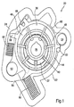
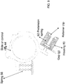
- variable capacity vane pump 20 in accordance with a prior art embodiment which is useful for understanding the invention as best shown FIG. 1 .
- the pump 20 includes a casing 22 with a front face 24 which is sealed with a pump cover (not shown) using any known or appropriate sealing device such as a suitable gasket seal.
- the pump 20 is coupled and sealed with an engine (not shown) or the like for which the pump 20 will supply a pressurized working fluid such as oil.
- the pump 20 includes a drive shaft 28 which is driven by any suitable driving device, such as a power take off from the engine or other mechanism to operate pump 20.
- a pump rotor 32 located within a pump chamber 36 is driven by the drive shaft 28.
- a series of movable or slidable pump vanes 40 rotate as the rotor 32 rotates.
- An outer end of each vane 40 engages an inner circumferential surface of a pump control ring 44 which forms the outer wall of pump chamber 36.
- the pump vanes 40 and the outer wall of pump chamber 36 divide the pump chamber into a series of expanding and contracting pumping chambers 48 that is further defined by the inner surface of the pump control ring 44 and the pump rotor 32.
- Pump control ring 44 is mounted within the casing 22 at a pivot pin 52 that allows the center of pump control ring 44 to be moved relative to the center of rotor 32.
- the volume of working fluid chambers 48 changes as the chambers 48 rotate around pump chamber 36, with their volume becoming larger at the low pressure side (the left hand side of pump chamber 36 in FIG. 1 ) of pump 20 and smaller at the high pressure side (the right hand side of pump chamber 36 in FIG. 1 ) of pump 20.
- This change in volume of working fluid chambers 48 generates the pumping action of pump 20, drawing working fluid from an inlet port 50 and pressurizing and delivering it to an outlet port 54.
- a primary return spring 56 engages tab 55 of control ring 44 and casing 22 to bias pump control ring 44 to the position, shown in FIG. 1 , wherein the pump 20 has a maximum eccentricity.
- Control chamber 60 is formed between pump casing 22, pump control ring 44, pivot pin 52 and a resilient seal 68, mounted on pump control ring 44 and abutting casing 22.
- the control chamber 60 is in direct fluid communication with pump outlet 54 such that pressurized working fluid from the pump 20 which is supplied to pump outlet 54 also fills control chamber 60.
- control chamber 60 need not be in direct fluid communication with pump outlet 54 and can instead be supplied from any suitable source of working fluid, such as from an oil gallery in an automotive engine being supplied by pump 20.
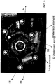
- the secondary control of the pump 20 is provided by the control ring 44 having a secondary tab 58 circumferentially spaced from the first or primary tab 55.
- Casing 22 is configured to house a secondary spring 62 in a pre-loaded state.
- Secondary spring 62 is a high rate spring relative to spring 56, preferably, which is a low rate spring.
- the casing 22 is configured to house spring 62 in a pre-loaded or compressed state or position.
- the secondary tab 58 of the control ring 44 is spaced a predetermined distance from the spring 62 by a gap 64, while the control ring 44 is in a maximum flow capacity state.
- pressurized working fluid in control chamber 60 acts against the pump control ring 44.
- the pump control ring 44 pivots about pivot pin 52, in a counter-clockwise direction as shown in Figs. 1 and 2 , to reduce the eccentricity of the pump 20.
- the pump control ring 44 remains pivoted clockwise about pivot pin 52 due to the force of the return spring 56, to increase the eccentricity of pump 20.
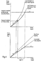
- the characteristics of the fluid (pressure and flow) at the output of the pump 20 can be graphed as a function of the operating speed of the pump. Referring to Fig. 4 , segment "a" of the graph represents the performance of the pump 20 when the eccentricity of the pump 20 is at a maximum when the control ring 44 is at the greatest clockwise position due to the force of the return spring 56 on the control ring 44.
- the flow of the fluid output by the pump 20 follows a fixed or maximum capacity line and the pressure of the fluid follows a load resistance curve that relates to this fixed capacity.
- Segment "b" on the graph represents the point at which the pre-load of the low rate return spring 56 is overcome by the pressure acting on the control ring 44 and the control ring 44 pivots.
- the pressure and flow of the fluid at the output remain substantially constant according to the equilibrium between the pressure and the spring force of the primary return spring 56.
- the secondary tab 58 is not in contact with the high rate spring 62.
- Segment "c" of the graph represents when the gap 64, as best shown in Fig. 3 , closes to zero and the secondary tab 58 contacts the high rate or secondary spring 62, but the pressure in chamber 60 is not sufficiently high enough to overcome the pre-load of the secondary spring 62.
- the eccentricity of the pump 20 therefore remains constant at this intermediate value and the output flow follows another (smaller) fixed capacity line.
- the pressure of the flow follows a new load resistance curve that relates to this lower value of pump displacement.
- Segment "d" of the graph of Fig. 4 represents when the fluid pressure acting in chamber 60 on the control ring 44 overcomes the pre-load of the high rate spring 62 and the control ring 44 again moves counter-clockwise on the pivot 52.
- the pump outlet pressure and flow remain substantially constant according to the equilibrium between the pressure in chamber 60 and the combined forces of springs 56 and 62.
- pump control ring 44 pivots about pivot pin 52, in the clockwise direction to increase the eccentricity of pump 20.
- FIGs 1-3 The arrangement of the first and second springs 56 and 62, respectively, is illustrated in FIGs 1-3 as being in separate housings within the casing 22.
- Fig. 5 shows an arrangement of the second spring 62.
- the variable capacity pump 20 includes a first control spring 62 associated with a first tab or extension member 55 of the control ring 44 similar to the embodiment of FIG. 1 .
- the pump 20 of Fig. 5 further includes the second spring 62 acting on the tab or second extension member 58 of the control ring 44.
- the pump 20 of FIG. 5 further includes a shaft having a first end passing through a hole or passage in the tab 58 and the shaft extends distal there from to a seconded defining a gap (g) with the housing 22.
- the first end of the shaft is coupled to the tab 58 of the control ring 44 using a pair of nuts for securing the shaft to the control ring 44 but may be coupled using any known or appropriate fastener or similar device.
- the second end of the shaft includes a pretension element formed or coupled at the second end to define a shoulder for trapping the spring 62 between the tab 58 and the pretension element of the second end of the shaft.
- the operation of the pump 20 of Fig. 5 can be similar to that of the prior art embodiment of Figs. 1-4 .
- pump 20 is generally very similar to the pump 20 of the other alternate exemplary embodiment of Fig. 5 except the shaft in Fig. 6 is coupled or secured in the passage in the tab 58 of the control ring 44 using a press-fitted collar.
- the press-fitted collar is designed to be secured to the first end of the shaft such that the shaft pretensions the second spring, trapped between the shoulder of the pretension element of the second end of the shaft and the tab 58 of the control ring while also defining the Gap (g) desired for having the variable capacity vane pump 20 according to FIG. 6 operate according to preferred operating curve shown in FIG. 4 .
- the pumps 20 are generally very similar to the pumps 20 of FIGs. 1 or 5 , except that the pumps 20 include a modular or second housing 80 for operating or holding the second control spring 62 and defining the Gap (g).
- the second housing 80 is a generally rectangular (in cross-section as shown in the figures) member having a first end aligned with the tab 58 of the control ring 44 and a second end distal from the first end.
- the second end is advantageously closed using a press-fitted plug for holding the second control spring 62 within the second housing 80 and transferring the force of the second spring 62 to the slide or control ring 44.
- the tab or extension member 58 of the control ring 44 includes a first portion and a second portion aligned at an angle from the first portion.
- the second portion is aligned toward the first end of the housing 80 to pass through a passage in the first end of the housing 80 and contact a first member for transferring the forces between the control ring 44 and the second spring 62.
- the opening in the first end of the housing 80 is designed to define the Gap (g) using the length of the first end of the housing 80.
- the second portion of the tab 58 travels through the Gap (g) distance until it contacts the first member transferring the force to the second spring 62 as the first member moves in the housing 80 toward the second end.
- the second portion of the tab 58 extending at an angle with respect to the second portion of the tab 58 can be advantageously used to define a limit of travel for the tab 58 and thus the control ring 44.
- the housing 80 is shown holding the first and second control springs 56 and 62, respectively.
- the housing 80 of FIG. 8 provides significantly improved packaging flexibility in the pumps 20 since the first and second control springs 56 and 62, respectively, may be more closely co-located.
- the first and second control springs 56 and 62, respectively are aligned parallel or side-by-side within the housing 80 and the first end of each of the first and second control springs 56 and 62, respectively, act against a common first portion or wall 82 extending within the housing 80.
- the spring housing 80 can be made more modular such that it can be manufactured either unitarily with the housing 22 of the pump 20 or separately and then made integral with the housing 22 or other part of the pump 20. Such a design for the housing 80 provides significantly greater design flexibility and utilization of the pump 20. While the housing 80 is shown having a generally rectangular cross section, it should be understood that other shapes are possible.
- the pump 20 includes the housing 80 and arrangements of the first and second springs 56 and 62, respectively.
- the common housing 80 is shown holding the first and second control springs 56 and 62, respectively, in an in-line or series arrangement as compared to the side-by-side or parallel arrangement shown in FIG. 8 .
- the housing 80 of FIGs. 10 and 11 also provides significantly improved packaging flexibility in the pump 20 since the first and second control springs 56 and 62, respectively, may be more closely aligned and co-located.
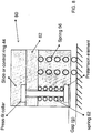
- the first and second control springs 56 and 62, respectively are aligned in-line within the housing 80. Referring in particular to FIG.
- the first spring 56 is located closest to the tab 58 of the control ring or slide 44 and the second control spring 62 is located distal.
- a pin having a substantially t-shape is located between the first and second springs 56 and 62, respectively.
- the tab 58 will first act on the spring 56 (Spring 1) over a given distance until the tab 58 contacts the pin and begins compressing the second spring 62 (Spring 2).
- the example shown in FIG. 11 is similar to that of FIG.
- the t-shaped pin is located between the first control spring 56 and the tab 58 of the control ring or slide 44 and a retainer is provided between the second control spring 62 and the second end of the pin such that once the first control spring 56 (Spring 1) compresses a given distance, the force from the tab 58 will begin to be applied against the force of the second control spring 62 (Spring 2).
Landscapes
- Engineering & Computer Science (AREA)
- Mechanical Engineering (AREA)
- General Engineering & Computer Science (AREA)
- Details And Applications Of Rotary Liquid Pumps (AREA)
- Rotary Pumps (AREA)
Claims (10)
- Eine Flügelzellenpumpe mit variabler Kapazität mit einem beweglichen Pumpensteuerring zum Ändern der Ausgangsleistung der Flügelzellenpumpe, wobei die Flügelzellenpumpe mit variabler Kapazität umfasst:ein Pumpengehäuse (22) mit einer Pumpenkammer (36) darin, wobei das Pumpengehäuse eine Einlassöffnung (50) und eine Auslassöffnung (54) hat;einen Flügelzellenpumpenrotor (32), der drehbar in der Pumpenkammer angebracht ist;einen Steuerring (44), der den Flügelzellenpumpenrotor innerhalb der Pumpenkammer umschließt,eine Mehrzahl von Schaufeln (40), die mit dem Rotor in Wirkverbindung stehen und reibschlüssig in Eingriff mit dem Steuerring stehen zum Pumpen eines Fluides aus der Einlassöffnung durch die Pumpenkammer hindurch und zu der Auslassöffnung, wobei der Steuerring innerhalb der Pumpenkammer bewegbar ist, um die volumetrische Kapazität der Pumpe zu ändern;eine variable Steuerkammer (60), durch das Pumpengehäuse und durch den Steuerring definiert, wobei die Steuerkammer dazu ausgebildet ist, um unter Druck stehendes Fluid zu empfangen, um eine Kraft zu erzeugen, um den Steuerring in Richtung einer Position der minimalen volumetrischen Kapazität der Pumpkammern zu leiten;eine erste Rückstellfeder (56) zum Lenken des Steuerringes in Richtung auf eine Position der größeren volumetrischen Kapazität der Pumpe, wobei die Kraft der ersten Rückstellfeder gegen die Kraft des Steuerringes wirkt, um ein erstes Gleichgewicht herzustellen; undeine zweite Rückstellfeder (62) zum Lenken des Steuerringes in Richtung auf eine Position der größeren volumetrischen Kapazität der Pumpe, wobei die Kraft der zweiten Rückstellfeder gegen die Kraft des Steuerringes wirkt, nachdem der Steuerring sich zumindest um einen ersten vorbestimmten Betrag gegen die Vorspannkraft der ersten Rückstellfeder bewegt hat;dadurch gekennzeichnet, dass die Flügelzellenpumpe ferner umfasst:eine Welle mit einem ersten Ende, das mit einer Lasche (58) des Steuerringes verbunden ist, und mit einem zweiten Ende, welches distal von dem ersten Ende und von dem Steuerring entfernt ist,wobei das zweite Ende der Welle in einem vorbestimmten Abstand (9) zu dem Gehäuse der Pumpe beabstandet ist, wobei das zweite Ende der Welle ein am zweiten Ende angekoppeltes Vorspannelement aufweist, um eine Schulter zum Einfangen der zweiten Feder (62) zwischen der Lasche (58) und dem Vorspannelement des zweiten Endes der Welle zu definieren, und wobei die zweite Feder (62) zwischen dem Steuerring (44) und dem zweiten Ende angeordnet ist.
- Flügelzellenpumpe mit variabler Kapazität nach Anspruch 1, wobei die zweite Rückstellfeder (62) vorbelastet ist.
- Flügelzellenpumpe mit variabler Kapazität nach einem der Ansprüche 1 bis 2, ferner umfassend ein zweites Gehäuse (80) zur Aufnahme mindestens eines Teils der zweiten Rückstellfeder (62) und der Welle.
- Flügelzellenpumpe mit variabler Kapazität nach Anspruch 3, wobei das zweite Gehäuse (80) ein erstes Ende und ein zweites geschlossenes Ende mit einem Presssitzstopfen aufweist.
- Flügelzellenpumpe mit variabler Kapazität nach Anspruch 3, wobei das zweite Gehäuse (80) ein erstes Ende und ein zweites geschlossenes Ende aufweist, das eine Halteklammer aufweist, die mit einer Schulter des zweiten Gehäuses gekoppelt ist zum Einfangen der zweiten Rückstellfeder (62) innerhalb des Gehäuses.
- Flügelzellenpumpe mit variabler Kapazität nach einem der Ansprüche 3 bis 5, wobei das zweite Gehäuse (80) zum Halten und Zusammenstellen der ersten Rückstellfeder und der zweiten Rückstellfeder (56, 62) dient.
- Flügelzellenpumpe mit variabler Kapazität nach Anspruch 6, wobei die erste Rückstellfeder und die zweite Rückstellfeder (56, 62) parallel ausgerichtet sind.
- Flügelzellenpumpe mit variabler Kapazität nach Anspruch 6, wobei die erste Rückstellfeder und die zweite Rückstellfeder (56, 62) in Reihe ausgerichtet sind.
- Flügelzellenpumpe mit variabler Kapazität nach Anspruch 8, ferner umfassend einen Zylinderstift im wesentlichen t-förmig zwischen der ersten Rückstellfeder und der zweiten Rückstellfeder (56, 62) und wobei die erste Steuerfeder und die zweite Steuerfeder innerhalb des zweiten Gehäuses (80) in einer Linie ausgerichtet sind.
- Flügelzellenpumpe mit variabler Kapazität nach einem der Ansprüche 3 bis 5 und 6 bis 9, wobei das zweite Gehäuse (80) einstückig mit dem Pumpengehäuse (22) ausgebildet ist.
Applications Claiming Priority (2)
| Application Number | Priority Date | Filing Date | Title |
|---|---|---|---|
| US201161544841P | 2011-10-07 | 2011-10-07 | |
| PCT/CA2012/000931 WO2013049929A1 (en) | 2011-10-07 | 2012-10-05 | Pre-compression dual spring pump control |
Publications (3)
| Publication Number | Publication Date |
|---|---|
| EP2764249A1 EP2764249A1 (de) | 2014-08-13 |
| EP2764249A4 EP2764249A4 (de) | 2015-07-15 |
| EP2764249B1 true EP2764249B1 (de) | 2017-06-21 |
Family
ID=48043147
Family Applications (1)
| Application Number | Title | Priority Date | Filing Date |
|---|---|---|---|
| EP12839078.8A Not-in-force EP2764249B1 (de) | 2011-10-07 | 2012-10-05 | Pumpensteuerung über eine vorkomprimierte doppelte feder |
Country Status (8)
| Country | Link |
|---|---|
| US (1) | US9651046B2 (de) |
| EP (1) | EP2764249B1 (de) |
| JP (1) | JP2014528539A (de) |
| KR (1) | KR20140074915A (de) |
| CN (1) | CN103857912B (de) |
| CA (1) | CA2851317A1 (de) |
| MX (1) | MX2014004217A (de) |
| WO (1) | WO2013049929A1 (de) |
Families Citing this family (8)
| Publication number | Priority date | Publication date | Assignee | Title |
|---|---|---|---|---|
| WO2016068971A1 (en) * | 2014-10-31 | 2016-05-06 | Melling Tool Comapny | Multiple pressure variable displacement pump with mechanical control |
| GB2537930A (en) * | 2015-05-01 | 2016-11-02 | Chongqing Changan Automobile Co Ltd | A hydraulic pump |
| CN107100839B (zh) * | 2017-06-09 | 2019-07-30 | 湖南机油泵股份有限公司 | 一种用于安装在转子式机油泵泵体中的内壳体 |
| US20200032791A1 (en) * | 2018-07-24 | 2020-01-30 | GM Global Technology Operations LLC | Spring structure with sliding element |
| KR20210149179A (ko) * | 2019-04-23 | 2021-12-08 | 스택폴 인터내셔널 엔지니어드 프로덕츠, 엘티디. | 제어 챔버를 위한 개선된 시일 조립체를 지닌 베인 펌프 |
| US11635076B2 (en) * | 2021-01-22 | 2023-04-25 | Slw Automotive Inc. | Variable displacement vane pump with improved pressure control and range |
| DE102021119936A1 (de) * | 2021-07-30 | 2023-02-02 | Schwäbische Hüttenwerke Automotive GmbH | Rotationspumpe mit Stellstrukturfeder mit versetzter Wirklinie |
| DE102022207497A1 (de) | 2022-07-21 | 2024-02-01 | Mahle International Gmbh | Flügelzellenpumpe |
Family Cites Families (6)
| Publication number | Priority date | Publication date | Assignee | Title |
|---|---|---|---|---|
| GB675840A (en) * | 1950-01-24 | 1952-07-16 | Gen Motors Corp | Improvements in and relating to variable stroke rotary fluid pumps |
| US2768585A (en) * | 1952-12-18 | 1956-10-30 | Schwitzer Corp | Pump control mechanism |
| JPH09147701A (ja) * | 1995-11-22 | 1997-06-06 | Mitsubishi Electric Corp | 真空開閉装置 |
| WO2006045188A1 (en) * | 2004-10-25 | 2006-05-04 | Magna Powertrain Inc. | Variable capacity vane pump with out-of-plane control |
| KR101259220B1 (ko) * | 2006-07-06 | 2013-04-29 | 마그나 파워트레인 인크. | 이중 스프링을 구비한 가변 용량 펌프 |
| JP4986726B2 (ja) * | 2007-06-14 | 2012-07-25 | 日立オートモティブシステムズ株式会社 | 可変容量形ポンプ |
-
2012
- 2012-10-05 EP EP12839078.8A patent/EP2764249B1/de not_active Not-in-force
- 2012-10-05 CA CA2851317A patent/CA2851317A1/en not_active Abandoned
- 2012-10-05 JP JP2014533743A patent/JP2014528539A/ja active Pending
- 2012-10-05 MX MX2014004217A patent/MX2014004217A/es unknown
- 2012-10-05 WO PCT/CA2012/000931 patent/WO2013049929A1/en not_active Ceased
- 2012-10-05 CN CN201280049493.7A patent/CN103857912B/zh active Active
- 2012-10-05 KR KR1020147008672A patent/KR20140074915A/ko not_active Withdrawn
-
2014
- 2014-04-04 US US14/245,046 patent/US9651046B2/en not_active Expired - Fee Related
Non-Patent Citations (1)
| Title |
|---|
| None * |
Also Published As
| Publication number | Publication date |
|---|---|
| US9651046B2 (en) | 2017-05-16 |
| KR20140074915A (ko) | 2014-06-18 |
| US20140294647A1 (en) | 2014-10-02 |
| EP2764249A1 (de) | 2014-08-13 |
| EP2764249A4 (de) | 2015-07-15 |
| WO2013049929A1 (en) | 2013-04-11 |
| MX2014004217A (es) | 2014-05-28 |
| JP2014528539A (ja) | 2014-10-27 |
| CN103857912A (zh) | 2014-06-11 |
| CN103857912B (zh) | 2016-08-17 |
| CA2851317A1 (en) | 2013-04-11 |
Similar Documents
| Publication | Publication Date | Title |
|---|---|---|
| EP2764249B1 (de) | Pumpensteuerung über eine vorkomprimierte doppelte feder | |
| US8011908B2 (en) | Variable capacity pump with dual springs | |
| EP2971779B1 (de) | Flügelzellenpumpe mit mehreren steuerkammern | |
| US8602749B2 (en) | Variable displacement vane pump | |
| US20090196780A1 (en) | Variable Displacement Vane Pump With Dual Control Chambers | |
| US9004882B2 (en) | Variable displacement vane pump having multiple dampening springs | |
| JP5116546B2 (ja) | 可変容量型ベーンポンプ | |
| CN103836321A (zh) | 可变容量型泵 | |
| CN103174644A (zh) | 可变容量型油泵 | |
| US10267310B2 (en) | Variable pressure pump with hydraulic passage | |
| CN104564666A (zh) | 叶片泵 | |
| US9206800B2 (en) | Multiple stage passive variable displacement vane pump | |
| CN101044322B (zh) | 具有可选出口压力的泵 | |
| US20170306948A1 (en) | Multiple Pressure Variable Displacement Pump with Mechanical Control | |
| WO2013038221A1 (en) | Single chamber variable displacement vane pump | |
| US12448967B2 (en) | Variable displacement oil pump |
Legal Events
| Date | Code | Title | Description |
|---|---|---|---|
| PUAI | Public reference made under article 153(3) epc to a published international application that has entered the european phase |
Free format text: ORIGINAL CODE: 0009012 |
|
| 17P | Request for examination filed |
Effective date: 20140425 |
|
| AK | Designated contracting states |
Kind code of ref document: A1 Designated state(s): AL AT BE BG CH CY CZ DE DK EE ES FI FR GB GR HR HU IE IS IT LI LT LU LV MC MK MT NL NO PL PT RO RS SE SI SK SM TR |
|
| DAX | Request for extension of the european patent (deleted) | ||
| RA4 | Supplementary search report drawn up and despatched (corrected) |
Effective date: 20150616 |
|
| RIC1 | Information provided on ipc code assigned before grant |
Ipc: F04C 2/344 20060101ALI20150610BHEP Ipc: F01M 1/02 20060101ALI20150610BHEP Ipc: F04C 14/20 20060101AFI20150610BHEP Ipc: F01M 1/16 20060101ALI20150610BHEP |
|
| GRAP | Despatch of communication of intention to grant a patent |
Free format text: ORIGINAL CODE: EPIDOSNIGR1 |
|
| STAA | Information on the status of an ep patent application or granted ep patent |
Free format text: STATUS: GRANT OF PATENT IS INTENDED |
|
| INTG | Intention to grant announced |
Effective date: 20170223 |
|
| GRAS | Grant fee paid |
Free format text: ORIGINAL CODE: EPIDOSNIGR3 |
|
| GRAA | (expected) grant |
Free format text: ORIGINAL CODE: 0009210 |
|
| STAA | Information on the status of an ep patent application or granted ep patent |
Free format text: STATUS: THE PATENT HAS BEEN GRANTED |
|
| AK | Designated contracting states |
Kind code of ref document: B1 Designated state(s): AL AT BE BG CH CY CZ DE DK EE ES FI FR GB GR HR HU IE IS IT LI LT LU LV MC MK MT NL NO PL PT RO RS SE SI SK SM TR |
|
| REG | Reference to a national code |
Ref country code: GB Ref legal event code: FG4D |
|
| REG | Reference to a national code |
Ref country code: CH Ref legal event code: EP |
|
| REG | Reference to a national code |
Ref country code: IE Ref legal event code: FG4D |
|
| REG | Reference to a national code |
Ref country code: AT Ref legal event code: REF Ref document number: 903219 Country of ref document: AT Kind code of ref document: T Effective date: 20170715 |
|
| REG | Reference to a national code |
Ref country code: DE Ref legal event code: R096 Ref document number: 602012033806 Country of ref document: DE |
|
| REG | Reference to a national code |
Ref country code: NL Ref legal event code: MP Effective date: 20170621 |
|
| PG25 | Lapsed in a contracting state [announced via postgrant information from national office to epo] |
Ref country code: NO Free format text: LAPSE BECAUSE OF FAILURE TO SUBMIT A TRANSLATION OF THE DESCRIPTION OR TO PAY THE FEE WITHIN THE PRESCRIBED TIME-LIMIT Effective date: 20170921 Ref country code: HR Free format text: LAPSE BECAUSE OF FAILURE TO SUBMIT A TRANSLATION OF THE DESCRIPTION OR TO PAY THE FEE WITHIN THE PRESCRIBED TIME-LIMIT Effective date: 20170621 Ref country code: FI Free format text: LAPSE BECAUSE OF FAILURE TO SUBMIT A TRANSLATION OF THE DESCRIPTION OR TO PAY THE FEE WITHIN THE PRESCRIBED TIME-LIMIT Effective date: 20170621 Ref country code: GR Free format text: LAPSE BECAUSE OF FAILURE TO SUBMIT A TRANSLATION OF THE DESCRIPTION OR TO PAY THE FEE WITHIN THE PRESCRIBED TIME-LIMIT Effective date: 20170922 Ref country code: LT Free format text: LAPSE BECAUSE OF FAILURE TO SUBMIT A TRANSLATION OF THE DESCRIPTION OR TO PAY THE FEE WITHIN THE PRESCRIBED TIME-LIMIT Effective date: 20170621 |
|
| REG | Reference to a national code |
Ref country code: LT Ref legal event code: MG4D |
|
| REG | Reference to a national code |
Ref country code: AT Ref legal event code: MK05 Ref document number: 903219 Country of ref document: AT Kind code of ref document: T Effective date: 20170621 |
|
| PG25 | Lapsed in a contracting state [announced via postgrant information from national office to epo] |
Ref country code: BG Free format text: LAPSE BECAUSE OF FAILURE TO SUBMIT A TRANSLATION OF THE DESCRIPTION OR TO PAY THE FEE WITHIN THE PRESCRIBED TIME-LIMIT Effective date: 20170921 Ref country code: NL Free format text: LAPSE BECAUSE OF FAILURE TO SUBMIT A TRANSLATION OF THE DESCRIPTION OR TO PAY THE FEE WITHIN THE PRESCRIBED TIME-LIMIT Effective date: 20170621 Ref country code: LV Free format text: LAPSE BECAUSE OF FAILURE TO SUBMIT A TRANSLATION OF THE DESCRIPTION OR TO PAY THE FEE WITHIN THE PRESCRIBED TIME-LIMIT Effective date: 20170621 Ref country code: RS Free format text: LAPSE BECAUSE OF FAILURE TO SUBMIT A TRANSLATION OF THE DESCRIPTION OR TO PAY THE FEE WITHIN THE PRESCRIBED TIME-LIMIT Effective date: 20170621 Ref country code: SE Free format text: LAPSE BECAUSE OF FAILURE TO SUBMIT A TRANSLATION OF THE DESCRIPTION OR TO PAY THE FEE WITHIN THE PRESCRIBED TIME-LIMIT Effective date: 20170621 |
|
| PG25 | Lapsed in a contracting state [announced via postgrant information from national office to epo] |
Ref country code: CZ Free format text: LAPSE BECAUSE OF FAILURE TO SUBMIT A TRANSLATION OF THE DESCRIPTION OR TO PAY THE FEE WITHIN THE PRESCRIBED TIME-LIMIT Effective date: 20170621 Ref country code: EE Free format text: LAPSE BECAUSE OF FAILURE TO SUBMIT A TRANSLATION OF THE DESCRIPTION OR TO PAY THE FEE WITHIN THE PRESCRIBED TIME-LIMIT Effective date: 20170621 Ref country code: SK Free format text: LAPSE BECAUSE OF FAILURE TO SUBMIT A TRANSLATION OF THE DESCRIPTION OR TO PAY THE FEE WITHIN THE PRESCRIBED TIME-LIMIT Effective date: 20170621 Ref country code: AT Free format text: LAPSE BECAUSE OF FAILURE TO SUBMIT A TRANSLATION OF THE DESCRIPTION OR TO PAY THE FEE WITHIN THE PRESCRIBED TIME-LIMIT Effective date: 20170621 Ref country code: RO Free format text: LAPSE BECAUSE OF FAILURE TO SUBMIT A TRANSLATION OF THE DESCRIPTION OR TO PAY THE FEE WITHIN THE PRESCRIBED TIME-LIMIT Effective date: 20170621 |
|
| PG25 | Lapsed in a contracting state [announced via postgrant information from national office to epo] |
Ref country code: IT Free format text: LAPSE BECAUSE OF FAILURE TO SUBMIT A TRANSLATION OF THE DESCRIPTION OR TO PAY THE FEE WITHIN THE PRESCRIBED TIME-LIMIT Effective date: 20170621 Ref country code: SM Free format text: LAPSE BECAUSE OF FAILURE TO SUBMIT A TRANSLATION OF THE DESCRIPTION OR TO PAY THE FEE WITHIN THE PRESCRIBED TIME-LIMIT Effective date: 20170621 Ref country code: IS Free format text: LAPSE BECAUSE OF FAILURE TO SUBMIT A TRANSLATION OF THE DESCRIPTION OR TO PAY THE FEE WITHIN THE PRESCRIBED TIME-LIMIT Effective date: 20171021 Ref country code: PL Free format text: LAPSE BECAUSE OF FAILURE TO SUBMIT A TRANSLATION OF THE DESCRIPTION OR TO PAY THE FEE WITHIN THE PRESCRIBED TIME-LIMIT Effective date: 20170621 Ref country code: ES Free format text: LAPSE BECAUSE OF FAILURE TO SUBMIT A TRANSLATION OF THE DESCRIPTION OR TO PAY THE FEE WITHIN THE PRESCRIBED TIME-LIMIT Effective date: 20170621 |
|
| REG | Reference to a national code |
Ref country code: DE Ref legal event code: R097 Ref document number: 602012033806 Country of ref document: DE |
|
| PLBE | No opposition filed within time limit |
Free format text: ORIGINAL CODE: 0009261 |
|
| STAA | Information on the status of an ep patent application or granted ep patent |
Free format text: STATUS: NO OPPOSITION FILED WITHIN TIME LIMIT |
|
| PG25 | Lapsed in a contracting state [announced via postgrant information from national office to epo] |
Ref country code: DK Free format text: LAPSE BECAUSE OF FAILURE TO SUBMIT A TRANSLATION OF THE DESCRIPTION OR TO PAY THE FEE WITHIN THE PRESCRIBED TIME-LIMIT Effective date: 20170621 |
|
| REG | Reference to a national code |
Ref country code: DE Ref legal event code: R119 Ref document number: 602012033806 Country of ref document: DE |
|
| 26N | No opposition filed |
Effective date: 20180322 |
|
| PG25 | Lapsed in a contracting state [announced via postgrant information from national office to epo] |
Ref country code: MC Free format text: LAPSE BECAUSE OF FAILURE TO SUBMIT A TRANSLATION OF THE DESCRIPTION OR TO PAY THE FEE WITHIN THE PRESCRIBED TIME-LIMIT Effective date: 20170621 |
|
| REG | Reference to a national code |
Ref country code: CH Ref legal event code: PL |
|
| GBPC | Gb: european patent ceased through non-payment of renewal fee |
Effective date: 20171005 |
|
| REG | Reference to a national code |
Ref country code: IE Ref legal event code: MM4A |
|
| REG | Reference to a national code |
Ref country code: FR Ref legal event code: ST Effective date: 20180629 |
|
| PG25 | Lapsed in a contracting state [announced via postgrant information from national office to epo] |
Ref country code: LI Free format text: LAPSE BECAUSE OF NON-PAYMENT OF DUE FEES Effective date: 20171031 Ref country code: CH Free format text: LAPSE BECAUSE OF NON-PAYMENT OF DUE FEES Effective date: 20171031 Ref country code: LU Free format text: LAPSE BECAUSE OF NON-PAYMENT OF DUE FEES Effective date: 20171005 Ref country code: GB Free format text: LAPSE BECAUSE OF NON-PAYMENT OF DUE FEES Effective date: 20171005 Ref country code: DE Free format text: LAPSE BECAUSE OF NON-PAYMENT OF DUE FEES Effective date: 20180501 |
|
| REG | Reference to a national code |
Ref country code: BE Ref legal event code: MM Effective date: 20171031 |
|
| PG25 | Lapsed in a contracting state [announced via postgrant information from national office to epo] |
Ref country code: FR Free format text: LAPSE BECAUSE OF NON-PAYMENT OF DUE FEES Effective date: 20171031 Ref country code: BE Free format text: LAPSE BECAUSE OF NON-PAYMENT OF DUE FEES Effective date: 20171031 Ref country code: SI Free format text: LAPSE BECAUSE OF FAILURE TO SUBMIT A TRANSLATION OF THE DESCRIPTION OR TO PAY THE FEE WITHIN THE PRESCRIBED TIME-LIMIT Effective date: 20170621 |
|
| PG25 | Lapsed in a contracting state [announced via postgrant information from national office to epo] |
Ref country code: MT Free format text: LAPSE BECAUSE OF NON-PAYMENT OF DUE FEES Effective date: 20171005 |
|
| PG25 | Lapsed in a contracting state [announced via postgrant information from national office to epo] |
Ref country code: IE Free format text: LAPSE BECAUSE OF NON-PAYMENT OF DUE FEES Effective date: 20171005 |
|
| PG25 | Lapsed in a contracting state [announced via postgrant information from national office to epo] |
Ref country code: HU Free format text: LAPSE BECAUSE OF FAILURE TO SUBMIT A TRANSLATION OF THE DESCRIPTION OR TO PAY THE FEE WITHIN THE PRESCRIBED TIME-LIMIT; INVALID AB INITIO Effective date: 20121005 |
|
| PG25 | Lapsed in a contracting state [announced via postgrant information from national office to epo] |
Ref country code: CY Free format text: LAPSE BECAUSE OF NON-PAYMENT OF DUE FEES Effective date: 20170621 |
|
| PG25 | Lapsed in a contracting state [announced via postgrant information from national office to epo] |
Ref country code: MK Free format text: LAPSE BECAUSE OF FAILURE TO SUBMIT A TRANSLATION OF THE DESCRIPTION OR TO PAY THE FEE WITHIN THE PRESCRIBED TIME-LIMIT Effective date: 20170621 |
|
| PG25 | Lapsed in a contracting state [announced via postgrant information from national office to epo] |
Ref country code: TR Free format text: LAPSE BECAUSE OF FAILURE TO SUBMIT A TRANSLATION OF THE DESCRIPTION OR TO PAY THE FEE WITHIN THE PRESCRIBED TIME-LIMIT Effective date: 20170621 |
|
| PG25 | Lapsed in a contracting state [announced via postgrant information from national office to epo] |
Ref country code: PT Free format text: LAPSE BECAUSE OF FAILURE TO SUBMIT A TRANSLATION OF THE DESCRIPTION OR TO PAY THE FEE WITHIN THE PRESCRIBED TIME-LIMIT Effective date: 20170621 |
|
| PG25 | Lapsed in a contracting state [announced via postgrant information from national office to epo] |
Ref country code: AL Free format text: LAPSE BECAUSE OF FAILURE TO SUBMIT A TRANSLATION OF THE DESCRIPTION OR TO PAY THE FEE WITHIN THE PRESCRIBED TIME-LIMIT Effective date: 20170621 |