EP2764212B1 - Disque aubage monobloc pourvu d'aubes a profil de pied adapte - Google Patents
Disque aubage monobloc pourvu d'aubes a profil de pied adapte Download PDFInfo
- Publication number
- EP2764212B1 EP2764212B1 EP12781370.7A EP12781370A EP2764212B1 EP 2764212 B1 EP2764212 B1 EP 2764212B1 EP 12781370 A EP12781370 A EP 12781370A EP 2764212 B1 EP2764212 B1 EP 2764212B1
- Authority
- EP
- European Patent Office
- Prior art keywords
- hub
- block
- bladed disk
- values
- blade
- Prior art date
- Legal status (The legal status is an assumption and is not a legal conclusion. Google has not performed a legal analysis and makes no representation as to the accuracy of the status listed.)
- Active
Links
Images


Classifications
-
- F—MECHANICAL ENGINEERING; LIGHTING; HEATING; WEAPONS; BLASTING
- F01—MACHINES OR ENGINES IN GENERAL; ENGINE PLANTS IN GENERAL; STEAM ENGINES
- F01D—NON-POSITIVE DISPLACEMENT MACHINES OR ENGINES, e.g. STEAM TURBINES
- F01D5/00—Blades; Blade-carrying members; Heating, heat-insulating, cooling or antivibration means on the blades or the members
- F01D5/12—Blades
-
- F—MECHANICAL ENGINEERING; LIGHTING; HEATING; WEAPONS; BLASTING
- F01—MACHINES OR ENGINES IN GENERAL; ENGINE PLANTS IN GENERAL; STEAM ENGINES
- F01D—NON-POSITIVE DISPLACEMENT MACHINES OR ENGINES, e.g. STEAM TURBINES
- F01D5/00—Blades; Blade-carrying members; Heating, heat-insulating, cooling or antivibration means on the blades or the members
- F01D5/12—Blades
- F01D5/14—Form or construction
-
- F—MECHANICAL ENGINEERING; LIGHTING; HEATING; WEAPONS; BLASTING
- F01—MACHINES OR ENGINES IN GENERAL; ENGINE PLANTS IN GENERAL; STEAM ENGINES
- F01D—NON-POSITIVE DISPLACEMENT MACHINES OR ENGINES, e.g. STEAM TURBINES
- F01D5/00—Blades; Blade-carrying members; Heating, heat-insulating, cooling or antivibration means on the blades or the members
- F01D5/12—Blades
- F01D5/14—Form or construction
- F01D5/141—Shape, i.e. outer, aerodynamic form
-
- F—MECHANICAL ENGINEERING; LIGHTING; HEATING; WEAPONS; BLASTING
- F01—MACHINES OR ENGINES IN GENERAL; ENGINE PLANTS IN GENERAL; STEAM ENGINES
- F01D—NON-POSITIVE DISPLACEMENT MACHINES OR ENGINES, e.g. STEAM TURBINES
- F01D5/00—Blades; Blade-carrying members; Heating, heat-insulating, cooling or antivibration means on the blades or the members
- F01D5/34—Rotor-blade aggregates of unitary construction, e.g. formed of sheet laminae
-
- F—MECHANICAL ENGINEERING; LIGHTING; HEATING; WEAPONS; BLASTING
- F04—POSITIVE - DISPLACEMENT MACHINES FOR LIQUIDS; PUMPS FOR LIQUIDS OR ELASTIC FLUIDS
- F04D—NON-POSITIVE-DISPLACEMENT PUMPS
- F04D29/00—Details, component parts, or accessories
- F04D29/26—Rotors specially for elastic fluids
- F04D29/32—Rotors specially for elastic fluids for axial flow pumps
- F04D29/321—Rotors specially for elastic fluids for axial flow pumps for axial flow compressors
- F04D29/324—Blades
-
- F—MECHANICAL ENGINEERING; LIGHTING; HEATING; WEAPONS; BLASTING
- F05—INDEXING SCHEMES RELATING TO ENGINES OR PUMPS IN VARIOUS SUBCLASSES OF CLASSES F01-F04
- F05D—INDEXING SCHEME FOR ASPECTS RELATING TO NON-POSITIVE-DISPLACEMENT MACHINES OR ENGINES, GAS-TURBINES OR JET-PROPULSION PLANTS
- F05D2240/00—Components
- F05D2240/20—Rotors
- F05D2240/30—Characteristics of rotor blades, i.e. of any element transforming dynamic fluid energy to or from rotational energy and being attached to a rotor
- F05D2240/301—Cross-sectional characteristics
-
- F—MECHANICAL ENGINEERING; LIGHTING; HEATING; WEAPONS; BLASTING
- F05—INDEXING SCHEMES RELATING TO ENGINES OR PUMPS IN VARIOUS SUBCLASSES OF CLASSES F01-F04
- F05D—INDEXING SCHEME FOR ASPECTS RELATING TO NON-POSITIVE-DISPLACEMENT MACHINES OR ENGINES, GAS-TURBINES OR JET-PROPULSION PLANTS
- F05D2250/00—Geometry
- F05D2250/70—Shape
-
- F—MECHANICAL ENGINEERING; LIGHTING; HEATING; WEAPONS; BLASTING
- F05—INDEXING SCHEMES RELATING TO ENGINES OR PUMPS IN VARIOUS SUBCLASSES OF CLASSES F01-F04
- F05D—INDEXING SCHEME FOR ASPECTS RELATING TO NON-POSITIVE-DISPLACEMENT MACHINES OR ENGINES, GAS-TURBINES OR JET-PROPULSION PLANTS
- F05D2250/00—Geometry
- F05D2250/70—Shape
- F05D2250/71—Shape curved
-
- Y—GENERAL TAGGING OF NEW TECHNOLOGICAL DEVELOPMENTS; GENERAL TAGGING OF CROSS-SECTIONAL TECHNOLOGIES SPANNING OVER SEVERAL SECTIONS OF THE IPC; TECHNICAL SUBJECTS COVERED BY FORMER USPC CROSS-REFERENCE ART COLLECTIONS [XRACs] AND DIGESTS
- Y02—TECHNOLOGIES OR APPLICATIONS FOR MITIGATION OR ADAPTATION AGAINST CLIMATE CHANGE
- Y02T—CLIMATE CHANGE MITIGATION TECHNOLOGIES RELATED TO TRANSPORTATION
- Y02T50/00—Aeronautics or air transport
- Y02T50/60—Efficient propulsion technologies, e.g. for aircraft
Definitions
- the subject of the invention is a monobloc blisk whose blades have a suitable foot profile.
- Such disks often abbreviated as "DAM” or "blisk” in English, comprise an integral circle of blades with a rotor core and are now of common use in aircraft engine turbomachines. , concurrently with the conventional blade stages where the vanes are manufactured separately from the rotor and assembled to it by a nesting of their feet in grooves cut into the surface thereof.
- the object of the invention is to improve monobloc bladed discs with regard to the resistance to static and vibratory forces, shocks on the occasion of ingestion of solid bodies in the engine, and the uniformity of distribution of the flow of gases on the height of the blades. It is particularly appreciable for engines working in intense conditions such as a supersonic flight with a Mach number of for example 1.45 at the engine inlet, a strong thrust controlling a hub ratio, equal to the radius of the hub. on the outer radius of the disk, 0.4 for example and a small elongation defined by the height-to-string ratio, which can be equal to 1.75.
- the invention is characterized in that the leading edges of the blades have, in a foot zone adjacent to the hub, a dihedral angle and an angle of deflection having continuously increasing values from minus 10 ° when approaching the hub. It has been found that this arrangement improves the dawn for aerodynamic performance and mechanical strength. The evolution of the arrow angle has a more pronounced effect on the first characteristic and the angle of dihedron on the second, but we can not dissociate them really.
- the foot zone extends about 20% to 30% of the height of the blade.
- Preferred forms of the invention have secondary features which will be detailed below, the effect of which is generally to enhance the main effect of the mentioned angle.
- the arrow angle and the dihedral angle have decreasing values continuously in a medial zone adjacent to the foot zone.
- the dihedral angle is always negative except for a portion of the foot zone that is closest to the hub.
- the angle of deflection has always positive values in a mid-dawn zone adjacent to the foot zone, although decreasing towards the foot zone, and has values greater than all those of the median zone in a portion of the zone. foot which is closest to the hub.
- the deflection angle advantageously reaches a maximum value of at least twice the values in the middle portion at the hub connection, which may be at least 20 °.
- the portion of the foot zone for which the dihedral angle is positive extends approximately 5% to 10% of the height of the blade, whereas the portion previously defined with respect to the angle of deflection extends about 10% to 20% of the height of the dawn.
- the invention also relates to a turbomachine comprising this monoblock blisk, in particular as compressor blower located all the way upstream of a gas flow through it.
- the Figure 1 partially represents a blisk, consisting of a hub (1), a holding with a circle of blades (2) distributed around its periphery.
- a disk can replace an ordinary rotating blade stage in a turbomachine, and it can be envisaged to place it as a fan at the inlet of the machine, as the first stage of the low pressure compressor.
- the angle of the arrow expresses the inclination of the blade in the axial direction, and the dihedral angle, the inclination of the dawn in tangential direction.
- a negative sign of the arrow angle expresses an upward inclination, and a positive sign, downstream; and a negative sign of the dihedral angle expresses an inclination towards the intrados, and a positive sign, towards the extrados.
- the inclinations are defined from radially outward direction.
- FIGS 4 and 5 illustrate the angles of arrow and dihedral respectively of the leading edge (3) of a blade (2) according to the invention, curves (4) and (5), the other curves being given for illustration and representing various designs of existing blades.
- the abscissae of the curves represent the values of the angles, and the ordinates the relative values of the spokes of the blade (2), of (0%) to the connection to the hub or foot to (100%) with the free edge or dawn's summit (2).
- the main effect of the characteristic of the invention is to ensure an optimal distribution of gas flow rate on the height of the blade (2), which increases the efficiency and facilitates the proper operation of the engine.
- the Figure 5 shows that the dihedral angle of the blade (2) is negative near the free edge, with values decreasing gradually down to the foot, then decreasing more strongly under a height of about 70% until reaching a minimum (from -13 °) to a height of about 20%; but from this height, the dihedral angle increases towards the connection to the hub (1), and here also faster and faster, until reaching positive values at a height of about 5% and a maximum positive angle (about 8 °) to the connection to the hub (1).
- the foot zone is quite original compared to the existing designs, which reveal different evolutions of the dihedral angle, but its persistence in all cases to negative values and lower than the one observed at the top of dawn.
- the foot zone begins at the inflection of the curve of the angle considered, and its height may differ for the two curves, but it is at most equal to 30% of the total height of the blade (2) approximately.
- the characteristic profile of the leading edge (3) in the foot region here ensures a reinforcement of the vanes (2) while maintaining acceptable mechanical stresses at the connection to the hub (1).
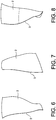
- Figures 6, 7 and 8 which illustrate dawn (2) in side, front and rear views: the Figure 6 allows to appreciate the influence of the angle of deflection, the leading edge (3) being approximately rectilinear in this view in the foot region, then bending to form a concavity in the upper regions of the dawn; and the Figures 7 and 8 clearly represent the change of direction of curvature of the leading edge (3) in the foot region, which distinguishes the invention from the existing designs set forth herein.
Landscapes
- Engineering & Computer Science (AREA)
- Mechanical Engineering (AREA)
- General Engineering & Computer Science (AREA)
- Physics & Mathematics (AREA)
- Fluid Mechanics (AREA)
- Ceramic Engineering (AREA)
- Structures Of Non-Positive Displacement Pumps (AREA)
Description
- Le sujet de l'invention est un disque aubagé monobloc dont les aubes ont un profil de pied adapté.
- De tels disques, abrégés souvent en « DAM », ou « blisk » en anglais, comprennent un cercle d'aubes d'un seul tenant avec un noyau de rotor et sont maintenant d'un emploi courant dans les turbomachines de moteurs d'avions, concurremment aux étages d'aubes classiques où les aubes sont fabriquées séparément du rotor et assemblées à lui par une imbrication de leurs pieds dans des rainures entaillant la surface de celui-ci.
- Il existe de très nombreux profils d'aubes, conçus pour donner de bonnes performances aérodynamiques ou une bonne tenue mécanique de résistance aux efforts ou aux vibrations. Les exemples existants ne sont toutefois pas forcément applicables à des disques aubagés monobloc, qui sont sujets à des contraintes particulières notamment du fait de la transmission intégrale et immédiate des contraintes entre le moyeu et les aubes ; cette remarque est d'autant plus valable que le moteur auquel appartient le disque aura une forte poussée.
- L'invention a pour objet l'amélioration des disques aubagés monobloc en ce qui concerne la résistance aux efforts statiques et vibratoires, aux chocs à l'occasion d'ingestion de corps solides dans le moteur, et l'uniformité de répartition de l'écoulement des gaz sur la hauteur des aubes. Elle est particulièrement appréciable pour des moteurs travaillant dans des conditions intenses telles qu'un vol supersonique avec un nombre de Mach de par exemple 1,45 à l'entrée du moteur, une forte poussée commandant un rapport de moyeu, égal au rayon du moyeu sur le rayon externe du disque, de 0,4 par exemple et un faible allongement défini par le rapport hauteur sur corde, pouvant être égal à 1,75.
- Les documents
US 2010/0054946 A etEP 1 505 302 A décrivent des aubes ayant des angles de flèche ou de dièdre croissant continûment en direction du moyeu dans une zone de pied de l'aube, mais souvent sur une faible hauteur de cette zone de pied, et les valeurs d'accroissement sont en général très faibles, trop faibles pour avoir un effet perceptible. Ces documents antérieurs s'intéressent en vérité plutôt aux caractéristiques des aubes à leur portion extérieure, opposée à la zone de pied à laquelle ils accordent très peu d'attention. - Sous une forme générale, l'invention est caractérisée en ce que les bords d'attaque des aubes ont, dans une zone de pied adjacente au moyeu, un angle de dièdre et un angle de flèche ayant des valeurs croissant continûment toutes deux d'au moins 10° en s'approchant du moyeu. Il a été constaté que cette disposition améliorait l'aube pour les performances aérodynamiques et sa résistance mécanique. L'évolution de l'angle de flèche a un effet plus prononcé sur la première caractéristique et l'angle de dièdre sur la seconde, mais sans qu'on puisse les dissocier vraiment.
- La zone de pied s'étend sur environ 20% à 30% de la hauteur de l'aube.
- Des formes préférées de l'invention possèdent des caractéristiques secondaires qu'on va détailler ci-dessous, dont l'effet est généralement de renforcer l'effet principal de l'angle mentionné.
- L'angle de flèche et l'angle de dièdre ont des valeurs décroissant continûment dans une zone médiane adjacente à la zone de pied.
- L'angle de dièdre est toujours négatif, sauf à une portion de la zone de pied qui est la plus proche du moyeu.
- L'angle de flèche a des valeurs toujours positives dans une zone médiane de l'aube adjacente à la zone de pied quoique décroissantes vers la zone de pied, et a des valeurs supérieures à toutes celles de la zone médiane dans une portion de la zone de pied qui est la plus proche du moyeu.
- Dans ce cas, l'angle de flèche atteint favorablement une valeur maximale d'au moins deux fois les valeurs dans la portion médiane au raccordement au moyeu, qui peut être de 20° au moins.
- La portion de la zone de pied pour laquelle l'angle de dièdre est positif s'étend sur environ 5% à 10% de la hauteur de l'aube, tandis que la portion précédemment définie à propos de l'angle de flèche s'étend sur environ 10% à 20% de la hauteur de l'aube.
- L'invention concerne aussi une turbomachine comprenant ce disque aubagé monobloc, notamment comme soufflante de compresseur située tout en amont d'un écoulement de gaz à travers elle.
- L'invention sera maintenant décrite plus en détail en liaison aux Figures suivantes, qui en représentent certains modes de réalisation à titre purement illustratif :
- la
Figure 1 est une vue générale d'un disque aubagé monobloc, - les
Figures 2 et 3 illustrent les significations des angles de flèche de dièdre, - les
Figures 4 et 5 donnent des courbes d'angles typiques de l'invention, - et les
Figures 6, 7 et 8 sont trois vues représentatives d'une aube. - La
Figure 1 représente partiellement un disque aubagé monobloc, composé d'un moyeu (1), d'un tenant avec un cercle d'aubes (2) réparties sur son pourtour. Un tel disque peut remplacer un étage d'aubes tournantes ordinaire dans une turbomachine, et on pourra envisager de le placer comme soufflante à l'entrée de la machine, comme premier étage du compresseur à basse pression. - On s'intéressera aux angles dits de flèche et de dièdre des aubes (2) à leur bord d'attaque. Ces angles mesurent les différences des directions entre l'écoulement et les aubes (2), en projection respectivement dans un plan radial et axial et un plan axial et tangent à la direction de rotation de la machine. Ils peuvent être exprimés, d'après les notations des
Figures 2 et 3 , par les équations suivantes, où λ désigne l'angle de flèche, ν l'angle de dièdre ; tan


- Si l'écoulement est purement axial, ce qui est à peu près le cas à l'entrée de la machine, l'angle de flèche exprime l'inclinaison de l'aube en direction axiale, et l'angle de dièdre, l'inclinaison de l'aube en direction tangentielle. Un signe négatif de l'angle de flèche exprime une inclinaison vers l'amont, et un signe positif, vers l'aval ; et un signe négatif de l'angle de dièdre exprime une inclinaison vers l'intrados, et un signe positif, vers l'extrados. Les inclinaisons sont définies à partir de direction radiales vers l'extérieur.
- Les
Figures 4 et 5 illustrent les angles de flèche et de dièdre respectivement du bord d'attaque (3) d'une aube (2) d'après l'invention, aux courbes (4) et (5), les autres courbes étant données à titre illustratif et représentant diverses conceptions d'aubes existantes. Les abscisses des courbes représentent les valeurs des angles, et les ordonnées les valeurs relatives des rayons de l'aube (2), de (0%) au raccordement au moyeu ou pied à (100%) au bord libre ou sommet de l'aube (2). En ce qui concerne l'angle de flèche, on voit que, du sommet au pied, il est d'abord négatif mais continument croissant, qu'il devient positif vers 75% de la hauteur tout en continuant de croître, qu'il atteint un maximum de 10° environ vers 45%, puis décroît tout en restant positif, atteint un minimum de 4° environ à environ 20% de la hauteur, puis, une zone de pied étant atteinte, qu'il se remet à croître continument, de plus en plus fortement et jusqu'à atteindre une valeur de 25° environ au raccordement au moyeu (1). Alors que cette courbe (4) ne se distingue pas nécessairement d'autres entre les hauteurs de 100% et 20%, la zone de pied entre la hauteur 20% et 0% est nettement originale, les autres courbes révélant soit peu de changement de l'angle de flèche à cet endroit, ou au contraire une décroissance de l'angle pour l'une d'entre elles. Une croissance de l'angle de flèche de 10° au moins entre les extrémités de la zone de pied (ici de 21° = 25° - 4° environ) caractérise l'invention. L'effet principal de la caractéristique de l'invention est d'assurer une répartition de débit d'écoulement des gaz optimale sur la hauteur de l'aube (2), ce qui accroît le rendement et facilite le bon fonctionnement du moteur. - La
Figure 5 montre que l'angle de dièdre de l'aube (2) est négatif près du bord libre, avec des valeurs décroissant peu à peu en descendant vers le pied, puis en décroissant plus fortement sous une hauteur de 70% environ jusqu'à atteindre un minimum (de -13° environ) à une hauteur de 20% environ ; mais à partir de cette hauteur, l'angle de dièdre croît vers le raccordement au moyeu (1), et ici aussi de plus en plus vite, jusqu'à atteindre des valeurs positives à une hauteur de 5% environ et un angle maximal positif (de 8° environ) au raccordement au moyeu (1). Ici encore la zone de pied est tout à fait originale par rapport aux conceptions existantes, qui révèlent des évolutions différentes de l'angle de dièdre, mais sa persistance dans tous les cas à des valeurs négatives et inférieures à celle qu'on observait au sommet de l'aube. Une croissance de l'angle de dièdre d'au moins 10° entre les extrémités de la zone de pied (ici de 21° = 13° + 8° environ) caractérise l'invention. La zone de pied commence à l'inflexion de la courbe de l'angle considéré, et sa hauteur peut différer pour les deux courbes, mais elle est au plus égale à 30% de la hauteur totale de l'aube (2) environ. Le profil caractéristique du bord d'attaque (3) dans la région de pied assure ici un renforcement des aubes (2) en maintenant des contraintes mécaniques acceptables au raccordement au moyeu (1). - On se reporte aux
Figures 6, 7 et 8 qui illustrent l'aube (2) en vues de côté, de l'avant et de l'arrière: laFigure 6 permet d'apprécier l'influence de l'angle de flèche, le bord d'attaque (3) étant à peu près rectiligne dans cette vue dans la région de pied, puis s'infléchissant pour former une concavité dans les régions supérieures de l'aube ; et lesFigures 7 et 8 représentent nettement le changement de direction de courbure du bord d'attaque (3) dans la région de pied, qui distingue l'invention des conceptions existantes exposées ici.
Claims (10)
- Disque aubagé monobloc pour turbomachine composé d'un moyeu (1) et d'aubes (2) reliées d'un tenant au moyen, où les bords d'attaque des aubes ont, dans une zone de pied adjacente au moyeu et s'étendant sur environ 20% à 30% de la hauteur de l'aube, un angle de dièdre et un angle de flèche (4) ayant des valeurs croissant continûment toutes deux et caractérisé en ce que l'accroissement des valeurs est d'au moins 10° en s'approchant du moyeu.
- Disque aubagé monobloc suivant la revendication 1, caractérisé en ce que l'angle de flèche et l'angle de dièdre ont des valeurs décroissant continûment dans une zone médiane de l'aube, adjacente à la zone de pied, en s'approchant du moyeu.
- Disque aubagé monobloc suivant l'une quelconque des revendications 1 ou 2, caractérisé en ce que l'angle de dièdre est toujours négatif, sauf à une portion de la zone de pied qui est la plus proche du moyeu.
- Disque aubagé monobloc suivant la revendication 1, caractérisé en ce que l'angle de flèche a des valeurs toujours positives dans une zone médiane de l'aube, et a des valeurs supérieures à toutes celles de la zone médiane dans une portion de la zone de pied qui est la plus proche du moyeu.
- Disque aubagé monobloc suivant la revendication 4, caractérisé en ce que l'angle de flèche atteint une valeur maximale d'au moins deux fois les valeurs dans la portion médiane au raccordement au moyeu.
- Disque aubagé monobloc suivant la revendication 5, caractérisé en ce que la valeur maximale est de 20° au moins.
- Disque aubagé monobloc suivant la revendication 3, caractérisé en ce que ladite portion de la zone de pied s'étend sur 5% à 10% de la hauteur de l'aube.
- Disque aubagé monobloc suivant l'une quelconques des revendications 4, 5 ou 6, caractérisé en ce que ladite portion de la zone de pied s'étend sur 10% à 20% de la hauteur de l'aube.
- Turbomachine, caractérisée en ce qu'elle comporte un disque aubagé monobloc suivant l'une quelconque des revendications précédentes.
- Turbomachine suivant la revendication 9, caractérisé en ce que le disque aubagé monobloc forme une soufflante de compresseur tout en amont d'un écoulement de gaz à travers la turbomachine.
Applications Claiming Priority (2)
| Application Number | Priority Date | Filing Date | Title |
|---|---|---|---|
| FR1159083A FR2981118B1 (fr) | 2011-10-07 | 2011-10-07 | Disque aubage monobloc pourvu d'aubes a profil de pied adapte |
| PCT/FR2012/052280 WO2013050724A1 (fr) | 2011-10-07 | 2012-10-08 | Disque aubage monobloc pourvu d'aubes a profil de pied adapte |
Publications (2)
| Publication Number | Publication Date |
|---|---|
| EP2764212A1 EP2764212A1 (fr) | 2014-08-13 |
| EP2764212B1 true EP2764212B1 (fr) | 2017-11-29 |
Family
ID=47143151
Family Applications (1)
| Application Number | Title | Priority Date | Filing Date |
|---|---|---|---|
| EP12781370.7A Active EP2764212B1 (fr) | 2011-10-07 | 2012-10-08 | Disque aubage monobloc pourvu d'aubes a profil de pied adapte |
Country Status (4)
| Country | Link |
|---|---|
| US (1) | US9677404B2 (fr) |
| EP (1) | EP2764212B1 (fr) |
| FR (1) | FR2981118B1 (fr) |
| WO (1) | WO2013050724A1 (fr) |
Families Citing this family (33)
| Publication number | Priority date | Publication date | Assignee | Title |
|---|---|---|---|---|
| FR3003598B1 (fr) | 2013-03-20 | 2018-04-06 | Safran Aircraft Engines | Aube et angle de diedre d'aube |
| EP3108113A4 (fr) | 2014-02-19 | 2017-03-15 | United Technologies Corporation | Profil aérodynamique de turbine à gaz |
| EP3108121B1 (fr) | 2014-02-19 | 2023-09-06 | Raytheon Technologies Corporation | Moteur à double flux à engrenage avec aubes de compresseur basse pression |
| EP3108100B1 (fr) | 2014-02-19 | 2021-04-14 | Raytheon Technologies Corporation | Pale de soufflante de moteur à turbine à gaz |
| EP4279706A3 (fr) | 2014-02-19 | 2024-02-28 | RTX Corporation | Aube de turbine à gaz |
| EP4509698A3 (fr) | 2014-02-19 | 2025-05-28 | RTX Corporation | Aube de turbine à gaz |
| US10519971B2 (en) | 2014-02-19 | 2019-12-31 | United Technologies Corporation | Gas turbine engine airfoil |
| US9567858B2 (en) | 2014-02-19 | 2017-02-14 | United Technologies Corporation | Gas turbine engine airfoil |
| WO2015175056A2 (fr) | 2014-02-19 | 2015-11-19 | United Technologies Corporation | Surface portante de moteur à turbine à gaz |
| US9140127B2 (en) | 2014-02-19 | 2015-09-22 | United Technologies Corporation | Gas turbine engine airfoil |
| EP4279747A3 (fr) | 2014-02-19 | 2024-03-13 | RTX Corporation | Aube de turbine à gaz |
| WO2015126941A1 (fr) | 2014-02-19 | 2015-08-27 | United Technologies Corporation | Profil aérodynamique de moteur à turbine à gaz |
| EP3114321B1 (fr) * | 2014-02-19 | 2019-04-17 | United Technologies Corporation | Profil aérodynamique de moteur à turbine à gaz |
| WO2015126454A1 (fr) | 2014-02-19 | 2015-08-27 | United Technologies Corporation | Surface portante de moteur à turbine à gaz |
| EP3108105B1 (fr) | 2014-02-19 | 2021-05-12 | Raytheon Technologies Corporation | Surface portante pour turbine à gaz |
| WO2015178974A2 (fr) | 2014-02-19 | 2015-11-26 | United Technologies Corporation | Surface portante de moteur à turbine à gaz |
| WO2015126715A1 (fr) | 2014-02-19 | 2015-08-27 | United Technologies Corporation | Profil aérodynamique de turbine à gaz |
| WO2015175052A2 (fr) | 2014-02-19 | 2015-11-19 | United Technologies Corporation | Profil aérodynamique de turbine à gaz |
| US9599064B2 (en) | 2014-02-19 | 2017-03-21 | United Technologies Corporation | Gas turbine engine airfoil |
| US10605259B2 (en) | 2014-02-19 | 2020-03-31 | United Technologies Corporation | Gas turbine engine airfoil |
| WO2015175044A2 (fr) | 2014-02-19 | 2015-11-19 | United Technologies Corporation | Profil aérodynamique de moteur à turbine à gaz |
| EP3108101B1 (fr) | 2014-02-19 | 2022-04-20 | Raytheon Technologies Corporation | Profil aérodynamique de moteur à turbine à gaz |
| EP3108106B1 (fr) * | 2014-02-19 | 2022-05-04 | Raytheon Technologies Corporation | Pale de moteur à turbine à gaz |
| US10443390B2 (en) | 2014-08-27 | 2019-10-15 | Pratt & Whitney Canada Corp. | Rotary airfoil |
| US9732762B2 (en) * | 2014-08-27 | 2017-08-15 | Pratt & Whitney Canada Corp. | Compressor airfoil |
| US9765795B2 (en) | 2014-08-27 | 2017-09-19 | Pratt & Whitney Canada Corp. | Compressor rotor airfoil |
| FR3028574B1 (fr) | 2014-11-17 | 2019-09-20 | Safran Aircraft Engines | Disque aubage monobloc pour soufflante de turbomachine comportant un evidement amont et ou aval conferant une plus grande flexibilite a ses aubes |
| US10414486B2 (en) * | 2015-11-30 | 2019-09-17 | General Electric Company | Airfoil for a rotary machine including a propellor assembly |
| US10221859B2 (en) | 2016-02-08 | 2019-03-05 | General Electric Company | Turbine engine compressor blade |
| CN110319057B (zh) * | 2019-07-18 | 2024-04-26 | 江苏精亚风机有限公司 | 一种前弯前掠偏装式叶片、叶轮及其轴流风机 |
| FR3115322B1 (fr) | 2020-10-20 | 2022-10-14 | Safran Aircraft Engines | Aube de soufflante à dièdre nul en tête |
| FR3129687B1 (fr) | 2021-11-29 | 2024-11-29 | Safran Aircraft Engines | Aube pour une hélice non carénée d’une turbomachine |
| FR3129686B1 (fr) | 2021-11-29 | 2024-07-12 | Safran Aircraft Engines | Aube pour une soufflante carénée d’une turbomachine |
Family Cites Families (21)
| Publication number | Priority date | Publication date | Assignee | Title |
|---|---|---|---|---|
| US2754919A (en) * | 1953-04-27 | 1956-07-17 | John R Blue | Propeller |
| US4131387A (en) * | 1976-02-27 | 1978-12-26 | General Electric Company | Curved blade turbomachinery noise reduction |
| US5190441A (en) * | 1990-08-13 | 1993-03-02 | General Electric Company | Noise reduction in aircraft propellers |
| US5167489A (en) * | 1991-04-15 | 1992-12-01 | General Electric Company | Forward swept rotor blade |
| US6071077A (en) * | 1996-04-09 | 2000-06-06 | Rolls-Royce Plc | Swept fan blade |
| US6328533B1 (en) * | 1999-12-21 | 2001-12-11 | General Electric Company | Swept barrel airfoil |
| JP4786077B2 (ja) * | 2001-08-10 | 2011-10-05 | 本田技研工業株式会社 | タービン用静翼及びその製造方法 |
| US6899526B2 (en) | 2003-08-05 | 2005-05-31 | General Electric Company | Counterstagger compressor airfoil |
| DE102004054752A1 (de) * | 2004-11-12 | 2006-05-18 | Rolls-Royce Deutschland Ltd & Co Kg | Schaufel einer Strömungsarbeitsmaschine mit erweiterter Randprofiltiefe |
| JP4719038B2 (ja) * | 2006-03-14 | 2011-07-06 | 三菱重工業株式会社 | 軸流流体機械用翼 |
| US7726937B2 (en) * | 2006-09-12 | 2010-06-01 | United Technologies Corporation | Turbine engine compressor vanes |
| US7967571B2 (en) * | 2006-11-30 | 2011-06-28 | General Electric Company | Advanced booster rotor blade |
| US7758306B2 (en) * | 2006-12-22 | 2010-07-20 | General Electric Company | Turbine assembly for a gas turbine engine and method of manufacturing the same |
| US7806653B2 (en) | 2006-12-22 | 2010-10-05 | General Electric Company | Gas turbine engines including multi-curve stator vanes and methods of assembling the same |
| US8147207B2 (en) * | 2008-09-04 | 2012-04-03 | Siemens Energy, Inc. | Compressor blade having a ratio of leading edge sweep to leading edge dihedral in a range of 1:1 to 3:1 along the radially outer portion |
| US8647067B2 (en) * | 2008-12-09 | 2014-02-11 | General Electric Company | Banked platform turbine blade |
| US8167567B2 (en) * | 2008-12-17 | 2012-05-01 | United Technologies Corporation | Gas turbine engine airfoil |
| JP5703750B2 (ja) * | 2010-12-28 | 2015-04-22 | 株式会社Ihi | ファン動翼及びファン |
| EP2476862B1 (fr) * | 2011-01-13 | 2013-11-20 | Alstom Technology Ltd | Aube statorique pour turbomachine à flux axial et turbomachine associée |
| US8702398B2 (en) * | 2011-03-25 | 2014-04-22 | General Electric Company | High camber compressor rotor blade |
| WO2015126454A1 (fr) * | 2014-02-19 | 2015-08-27 | United Technologies Corporation | Surface portante de moteur à turbine à gaz |
-
2011
- 2011-10-07 FR FR1159083A patent/FR2981118B1/fr active Active
-
2012
- 2012-10-08 EP EP12781370.7A patent/EP2764212B1/fr active Active
- 2012-10-08 US US14/348,770 patent/US9677404B2/en active Active
- 2012-10-08 WO PCT/FR2012/052280 patent/WO2013050724A1/fr not_active Ceased
Also Published As
| Publication number | Publication date |
|---|---|
| FR2981118A1 (fr) | 2013-04-12 |
| EP2764212A1 (fr) | 2014-08-13 |
| US9677404B2 (en) | 2017-06-13 |
| US20140248155A1 (en) | 2014-09-04 |
| FR2981118B1 (fr) | 2016-01-29 |
| WO2013050724A1 (fr) | 2013-04-11 |
Similar Documents
| Publication | Publication Date | Title |
|---|---|---|
| WO2013050724A1 (fr) | Disque aubage monobloc pourvu d'aubes a profil de pied adapte | |
| EP3030749B1 (fr) | Aube mobile de turbomachine | |
| CA2826153C (fr) | Ensemble pale-plateforme pour ecoulement subsonique | |
| EP2809883B1 (fr) | Aube pour soufflante de turboreacteur | |
| EP3477057B1 (fr) | Modulation des serrations en extrémité d'aube | |
| CA2327850C (fr) | Profils aerodynamiques d'aubes en fleche | |
| WO2013079851A1 (fr) | Aube de turbomachine notamment pour disque aubage monobloc | |
| WO2009138445A1 (fr) | Pale de rouet de compresseur a raccordement elliptique evolutif | |
| EP3394398B1 (fr) | Bouclier de bord d'attaque | |
| WO2018138439A1 (fr) | Profil amélioré de bord d'attaque d'aubes | |
| FR3103231A1 (fr) | Turbomachine à aubes ondulées | |
| US20150267545A1 (en) | Blisk with low stresses at blade root, preferably for an aircraft turbine engine fan | |
| EP2582986B1 (fr) | Couplage aérodynamique entre deux rangées annulaires d'aubes fixes dans une turbomachine | |
| EP3473813A1 (fr) | Turbomachine comprenant un ensemble de redressement | |
| CA2994912A1 (fr) | Aube de rotor de turbomachine | |
| WO2023021258A1 (fr) | Pièce statorique d'une turbomachine comprenant une pale et une ailette définissant entre elles une surface décroissante d'amont en aval selon le sens d'écoulement des gaz | |
| EP4508311B1 (fr) | Pièce statorique à ailette dans une turbomachine | |
| EP4508310B1 (fr) | Pièce statorique à ailette dans une turbomachine | |
| WO2014147332A1 (fr) | Aube et angle de diedre d'aube | |
| EP3768950B2 (fr) | Disque aubagé monobloc souple en partie basse des aubes | |
| EP4536977B1 (fr) | Ensemble de production de poussée non caréné comprenant un redresseur | |
| EP4569209B1 (fr) | Aube à calage variable de stator de turbomachine d'aéronef et turbomachine d'aéronef | |
| WO2025114454A1 (fr) | Aube pour compresseur de turbomachine d'aéronef, compresseur, turbomachine | |
| WO2025114465A1 (fr) | Ensemble de turbomachine | |
| EP4584477A1 (fr) | Aube directrice destinée à être fixée sur une virole de stator d'un moteur à turbine à gaz, assemblage de stator de moteur à turbine à gaz et moteur à turbine à gaz |
Legal Events
| Date | Code | Title | Description |
|---|---|---|---|
| PUAI | Public reference made under article 153(3) epc to a published international application that has entered the european phase |
Free format text: ORIGINAL CODE: 0009012 |
|
| 17P | Request for examination filed |
Effective date: 20140331 |
|
| AK | Designated contracting states |
Kind code of ref document: A1 Designated state(s): AL AT BE BG CH CY CZ DE DK EE ES FI FR GB GR HR HU IE IS IT LI LT LU LV MC MK MT NL NO PL PT RO RS SE SI SK SM TR |
|
| DAX | Request for extension of the european patent (deleted) | ||
| STAA | Information on the status of an ep patent application or granted ep patent |
Free format text: STATUS: EXAMINATION IS IN PROGRESS |
|
| 17Q | First examination report despatched |
Effective date: 20161213 |
|
| GRAP | Despatch of communication of intention to grant a patent |
Free format text: ORIGINAL CODE: EPIDOSNIGR1 |
|
| STAA | Information on the status of an ep patent application or granted ep patent |
Free format text: STATUS: GRANT OF PATENT IS INTENDED |
|
| INTG | Intention to grant announced |
Effective date: 20170530 |
|
| GRAS | Grant fee paid |
Free format text: ORIGINAL CODE: EPIDOSNIGR3 |
|
| GRAA | (expected) grant |
Free format text: ORIGINAL CODE: 0009210 |
|
| STAA | Information on the status of an ep patent application or granted ep patent |
Free format text: STATUS: THE PATENT HAS BEEN GRANTED |
|
| AK | Designated contracting states |
Kind code of ref document: B1 Designated state(s): AL AT BE BG CH CY CZ DE DK EE ES FI FR GB GR HR HU IE IS IT LI LT LU LV MC MK MT NL NO PL PT RO RS SE SI SK SM TR |
|
| REG | Reference to a national code |
Ref country code: CH Ref legal event code: EP |
|
| REG | Reference to a national code |
Ref country code: AT Ref legal event code: REF Ref document number: 950584 Country of ref document: AT Kind code of ref document: T Effective date: 20171215 |
|
| REG | Reference to a national code |
Ref country code: IE Ref legal event code: FG4D Free format text: LANGUAGE OF EP DOCUMENT: FRENCH |
|
| REG | Reference to a national code |
Ref country code: DE Ref legal event code: R096 Ref document number: 602012040381 Country of ref document: DE |
|
| REG | Reference to a national code |
Ref country code: SE Ref legal event code: TRGR |
|
| REG | Reference to a national code |
Ref country code: NL Ref legal event code: MP Effective date: 20171129 |
|
| REG | Reference to a national code |
Ref country code: LT Ref legal event code: MG4D |
|
| REG | Reference to a national code |
Ref country code: AT Ref legal event code: MK05 Ref document number: 950584 Country of ref document: AT Kind code of ref document: T Effective date: 20171129 |
|
| PG25 | Lapsed in a contracting state [announced via postgrant information from national office to epo] |
Ref country code: ES Free format text: LAPSE BECAUSE OF FAILURE TO SUBMIT A TRANSLATION OF THE DESCRIPTION OR TO PAY THE FEE WITHIN THE PRESCRIBED TIME-LIMIT Effective date: 20171129 Ref country code: FI Free format text: LAPSE BECAUSE OF FAILURE TO SUBMIT A TRANSLATION OF THE DESCRIPTION OR TO PAY THE FEE WITHIN THE PRESCRIBED TIME-LIMIT Effective date: 20171129 Ref country code: NO Free format text: LAPSE BECAUSE OF FAILURE TO SUBMIT A TRANSLATION OF THE DESCRIPTION OR TO PAY THE FEE WITHIN THE PRESCRIBED TIME-LIMIT Effective date: 20180228 Ref country code: LT Free format text: LAPSE BECAUSE OF FAILURE TO SUBMIT A TRANSLATION OF THE DESCRIPTION OR TO PAY THE FEE WITHIN THE PRESCRIBED TIME-LIMIT Effective date: 20171129 |
|
| PG25 | Lapsed in a contracting state [announced via postgrant information from national office to epo] |
Ref country code: RS Free format text: LAPSE BECAUSE OF FAILURE TO SUBMIT A TRANSLATION OF THE DESCRIPTION OR TO PAY THE FEE WITHIN THE PRESCRIBED TIME-LIMIT Effective date: 20171129 Ref country code: BG Free format text: LAPSE BECAUSE OF FAILURE TO SUBMIT A TRANSLATION OF THE DESCRIPTION OR TO PAY THE FEE WITHIN THE PRESCRIBED TIME-LIMIT Effective date: 20180228 Ref country code: AT Free format text: LAPSE BECAUSE OF FAILURE TO SUBMIT A TRANSLATION OF THE DESCRIPTION OR TO PAY THE FEE WITHIN THE PRESCRIBED TIME-LIMIT Effective date: 20171129 Ref country code: LV Free format text: LAPSE BECAUSE OF FAILURE TO SUBMIT A TRANSLATION OF THE DESCRIPTION OR TO PAY THE FEE WITHIN THE PRESCRIBED TIME-LIMIT Effective date: 20171129 Ref country code: GR Free format text: LAPSE BECAUSE OF FAILURE TO SUBMIT A TRANSLATION OF THE DESCRIPTION OR TO PAY THE FEE WITHIN THE PRESCRIBED TIME-LIMIT Effective date: 20180301 Ref country code: HR Free format text: LAPSE BECAUSE OF FAILURE TO SUBMIT A TRANSLATION OF THE DESCRIPTION OR TO PAY THE FEE WITHIN THE PRESCRIBED TIME-LIMIT Effective date: 20171129 |
|
| REG | Reference to a national code |
Ref country code: CH Ref legal event code: PFA Owner name: SAFRAN AIRCRAFT ENGINES, FR Free format text: FORMER OWNER: SNECMA, FR |
|
| PG25 | Lapsed in a contracting state [announced via postgrant information from national office to epo] |
Ref country code: NL Free format text: LAPSE BECAUSE OF FAILURE TO SUBMIT A TRANSLATION OF THE DESCRIPTION OR TO PAY THE FEE WITHIN THE PRESCRIBED TIME-LIMIT Effective date: 20171129 |
|
| RAP2 | Party data changed (patent owner data changed or rights of a patent transferred) |
Owner name: SAFRAN AIRCRAFT ENGINES |
|
| PG25 | Lapsed in a contracting state [announced via postgrant information from national office to epo] |
Ref country code: SK Free format text: LAPSE BECAUSE OF FAILURE TO SUBMIT A TRANSLATION OF THE DESCRIPTION OR TO PAY THE FEE WITHIN THE PRESCRIBED TIME-LIMIT Effective date: 20171129 Ref country code: DK Free format text: LAPSE BECAUSE OF FAILURE TO SUBMIT A TRANSLATION OF THE DESCRIPTION OR TO PAY THE FEE WITHIN THE PRESCRIBED TIME-LIMIT Effective date: 20171129 Ref country code: CZ Free format text: LAPSE BECAUSE OF FAILURE TO SUBMIT A TRANSLATION OF THE DESCRIPTION OR TO PAY THE FEE WITHIN THE PRESCRIBED TIME-LIMIT Effective date: 20171129 Ref country code: CY Free format text: LAPSE BECAUSE OF FAILURE TO SUBMIT A TRANSLATION OF THE DESCRIPTION OR TO PAY THE FEE WITHIN THE PRESCRIBED TIME-LIMIT Effective date: 20171129 Ref country code: EE Free format text: LAPSE BECAUSE OF FAILURE TO SUBMIT A TRANSLATION OF THE DESCRIPTION OR TO PAY THE FEE WITHIN THE PRESCRIBED TIME-LIMIT Effective date: 20171129 |
|
| REG | Reference to a national code |
Ref country code: DE Ref legal event code: R097 Ref document number: 602012040381 Country of ref document: DE |
|
| PG25 | Lapsed in a contracting state [announced via postgrant information from national office to epo] |
Ref country code: PL Free format text: LAPSE BECAUSE OF FAILURE TO SUBMIT A TRANSLATION OF THE DESCRIPTION OR TO PAY THE FEE WITHIN THE PRESCRIBED TIME-LIMIT Effective date: 20171129 Ref country code: SM Free format text: LAPSE BECAUSE OF FAILURE TO SUBMIT A TRANSLATION OF THE DESCRIPTION OR TO PAY THE FEE WITHIN THE PRESCRIBED TIME-LIMIT Effective date: 20171129 Ref country code: RO Free format text: LAPSE BECAUSE OF FAILURE TO SUBMIT A TRANSLATION OF THE DESCRIPTION OR TO PAY THE FEE WITHIN THE PRESCRIBED TIME-LIMIT Effective date: 20171129 |
|
| REG | Reference to a national code |
Ref country code: FR Ref legal event code: PLFP Year of fee payment: 7 |
|
| PG25 | Lapsed in a contracting state [announced via postgrant information from national office to epo] |
Ref country code: MT Free format text: LAPSE BECAUSE OF FAILURE TO SUBMIT A TRANSLATION OF THE DESCRIPTION OR TO PAY THE FEE WITHIN THE PRESCRIBED TIME-LIMIT Effective date: 20171129 |
|
| PLBE | No opposition filed within time limit |
Free format text: ORIGINAL CODE: 0009261 |
|
| STAA | Information on the status of an ep patent application or granted ep patent |
Free format text: STATUS: NO OPPOSITION FILED WITHIN TIME LIMIT |
|
| 26N | No opposition filed |
Effective date: 20180830 |
|
| PG25 | Lapsed in a contracting state [announced via postgrant information from national office to epo] |
Ref country code: SI Free format text: LAPSE BECAUSE OF FAILURE TO SUBMIT A TRANSLATION OF THE DESCRIPTION OR TO PAY THE FEE WITHIN THE PRESCRIBED TIME-LIMIT Effective date: 20171129 |
|
| REG | Reference to a national code |
Ref country code: CH Ref legal event code: PL |
|
| REG | Reference to a national code |
Ref country code: BE Ref legal event code: MM Effective date: 20181031 |
|
| PG25 | Lapsed in a contracting state [announced via postgrant information from national office to epo] |
Ref country code: LU Free format text: LAPSE BECAUSE OF NON-PAYMENT OF DUE FEES Effective date: 20181008 Ref country code: MC Free format text: LAPSE BECAUSE OF FAILURE TO SUBMIT A TRANSLATION OF THE DESCRIPTION OR TO PAY THE FEE WITHIN THE PRESCRIBED TIME-LIMIT Effective date: 20171129 |
|
| REG | Reference to a national code |
Ref country code: IE Ref legal event code: MM4A |
|
| PG25 | Lapsed in a contracting state [announced via postgrant information from national office to epo] |
Ref country code: BE Free format text: LAPSE BECAUSE OF NON-PAYMENT OF DUE FEES Effective date: 20181031 Ref country code: LI Free format text: LAPSE BECAUSE OF NON-PAYMENT OF DUE FEES Effective date: 20181031 Ref country code: CH Free format text: LAPSE BECAUSE OF NON-PAYMENT OF DUE FEES Effective date: 20181031 |
|
| PG25 | Lapsed in a contracting state [announced via postgrant information from national office to epo] |
Ref country code: IE Free format text: LAPSE BECAUSE OF NON-PAYMENT OF DUE FEES Effective date: 20181008 |
|
| PG25 | Lapsed in a contracting state [announced via postgrant information from national office to epo] |
Ref country code: TR Free format text: LAPSE BECAUSE OF FAILURE TO SUBMIT A TRANSLATION OF THE DESCRIPTION OR TO PAY THE FEE WITHIN THE PRESCRIBED TIME-LIMIT Effective date: 20171129 |
|
| PG25 | Lapsed in a contracting state [announced via postgrant information from national office to epo] |
Ref country code: PT Free format text: LAPSE BECAUSE OF FAILURE TO SUBMIT A TRANSLATION OF THE DESCRIPTION OR TO PAY THE FEE WITHIN THE PRESCRIBED TIME-LIMIT Effective date: 20171129 |
|
| PG25 | Lapsed in a contracting state [announced via postgrant information from national office to epo] |
Ref country code: MK Free format text: LAPSE BECAUSE OF NON-PAYMENT OF DUE FEES Effective date: 20171129 Ref country code: HU Free format text: LAPSE BECAUSE OF FAILURE TO SUBMIT A TRANSLATION OF THE DESCRIPTION OR TO PAY THE FEE WITHIN THE PRESCRIBED TIME-LIMIT; INVALID AB INITIO Effective date: 20121008 |
|
| PG25 | Lapsed in a contracting state [announced via postgrant information from national office to epo] |
Ref country code: AL Free format text: LAPSE BECAUSE OF FAILURE TO SUBMIT A TRANSLATION OF THE DESCRIPTION OR TO PAY THE FEE WITHIN THE PRESCRIBED TIME-LIMIT Effective date: 20171129 Ref country code: IS Free format text: LAPSE BECAUSE OF FAILURE TO SUBMIT A TRANSLATION OF THE DESCRIPTION OR TO PAY THE FEE WITHIN THE PRESCRIBED TIME-LIMIT Effective date: 20180329 |
|
| PGFP | Annual fee paid to national office [announced via postgrant information from national office to epo] |
Ref country code: DE Payment date: 20251020 Year of fee payment: 14 |
|
| PGFP | Annual fee paid to national office [announced via postgrant information from national office to epo] |
Ref country code: GB Payment date: 20251029 Year of fee payment: 14 |
|
| PGFP | Annual fee paid to national office [announced via postgrant information from national office to epo] |
Ref country code: IT Payment date: 20251031 Year of fee payment: 14 |
|
| PGFP | Annual fee paid to national office [announced via postgrant information from national office to epo] |
Ref country code: FR Payment date: 20251023 Year of fee payment: 14 |
|
| PGFP | Annual fee paid to national office [announced via postgrant information from national office to epo] |
Ref country code: SE Payment date: 20251023 Year of fee payment: 14 |