EP2763379A1 - Portable electronic apparatus - Google Patents
Portable electronic apparatus Download PDFInfo
- Publication number
- EP2763379A1 EP2763379A1 EP12836082.3A EP12836082A EP2763379A1 EP 2763379 A1 EP2763379 A1 EP 2763379A1 EP 12836082 A EP12836082 A EP 12836082A EP 2763379 A1 EP2763379 A1 EP 2763379A1
- Authority
- EP
- European Patent Office
- Prior art keywords
- piezoelectric element
- housing
- electronic device
- mobile electronic
- user
- Prior art date
- Legal status (The legal status is an assumption and is not a legal conclusion. Google has not performed a legal analysis and makes no representation as to the accuracy of the status listed.)
- Withdrawn
Links
- 239000000758 substrate Substances 0.000 claims description 27
- 238000000465 moulding Methods 0.000 claims description 8
- 229920005989 resin Polymers 0.000 claims description 8
- 239000011347 resin Substances 0.000 claims description 8
- 239000006059 cover glass Substances 0.000 description 47
- 210000000845 cartilage Anatomy 0.000 description 14
- 210000002414 leg Anatomy 0.000 description 8
- 210000004728 ear cartilage Anatomy 0.000 description 7
- 239000011521 glass Substances 0.000 description 7
- 230000005236 sound signal Effects 0.000 description 6
- 230000005540 biological transmission Effects 0.000 description 5
- 239000003822 epoxy resin Substances 0.000 description 4
- 210000001699 lower leg Anatomy 0.000 description 4
- 239000002184 metal Substances 0.000 description 4
- 238000000034 method Methods 0.000 description 4
- 229920000647 polyepoxide Polymers 0.000 description 4
- 230000008569 process Effects 0.000 description 4
- 239000000919 ceramic Substances 0.000 description 3
- 238000003475 lamination Methods 0.000 description 3
- 239000000463 material Substances 0.000 description 3
- 210000003454 tympanic membrane Anatomy 0.000 description 3
- 241000746998 Tragus Species 0.000 description 2
- 230000008859 change Effects 0.000 description 2
- 210000000860 cochlear nerve Anatomy 0.000 description 2
- 210000000613 ear canal Anatomy 0.000 description 2
- 239000004744 fabric Substances 0.000 description 2
- 230000006870 function Effects 0.000 description 2
- 229910052451 lead zirconate titanate Inorganic materials 0.000 description 2
- 239000007788 liquid Substances 0.000 description 2
- 230000007246 mechanism Effects 0.000 description 2
- 230000004048 modification Effects 0.000 description 2
- 238000012986 modification Methods 0.000 description 2
- 230000009467 reduction Effects 0.000 description 2
- 229920000544 Gore-Tex Polymers 0.000 description 1
- 230000003321 amplification Effects 0.000 description 1
- 238000005452 bending Methods 0.000 description 1
- 230000008602 contraction Effects 0.000 description 1
- 238000001514 detection method Methods 0.000 description 1
- 238000010586 diagram Methods 0.000 description 1
- 210000000624 ear auricle Anatomy 0.000 description 1
- 210000005069 ears Anatomy 0.000 description 1
- 230000000694 effects Effects 0.000 description 1
- 238000005401 electroluminescence Methods 0.000 description 1
- VJYFKVYYMZPMAB-UHFFFAOYSA-N ethoprophos Chemical compound CCCSP(=O)(OCC)SCCC VJYFKVYYMZPMAB-UHFFFAOYSA-N 0.000 description 1
- 238000010438 heat treatment Methods 0.000 description 1
- 238000010030 laminating Methods 0.000 description 1
- HFGPZNIAWCZYJU-UHFFFAOYSA-N lead zirconate titanate Chemical compound [O-2].[O-2].[O-2].[O-2].[O-2].[Ti+4].[Zr+4].[Pb+2] HFGPZNIAWCZYJU-UHFFFAOYSA-N 0.000 description 1
- 239000004973 liquid crystal related substance Substances 0.000 description 1
- 239000000203 mixture Substances 0.000 description 1
- 238000003199 nucleic acid amplification method Methods 0.000 description 1
- 239000004033 plastic Substances 0.000 description 1
- 238000003825 pressing Methods 0.000 description 1
- 239000004065 semiconductor Substances 0.000 description 1
- 230000035939 shock Effects 0.000 description 1
- 125000006850 spacer group Chemical group 0.000 description 1
- 229920001187 thermosetting polymer Polymers 0.000 description 1
Images




Classifications
-
- H—ELECTRICITY
- H04—ELECTRIC COMMUNICATION TECHNIQUE
- H04M—TELEPHONIC COMMUNICATION
- H04M1/00—Substation equipment, e.g. for use by subscribers
- H04M1/02—Constructional features of telephone sets
- H04M1/0202—Portable telephone sets, e.g. cordless phones, mobile phones or bar type handsets
-
- H—ELECTRICITY
- H04—ELECTRIC COMMUNICATION TECHNIQUE
- H04M—TELEPHONIC COMMUNICATION
- H04M1/00—Substation equipment, e.g. for use by subscribers
- H04M1/02—Constructional features of telephone sets
- H04M1/03—Constructional features of telephone transmitters or receivers, e.g. telephone hand-sets
-
- H—ELECTRICITY
- H04—ELECTRIC COMMUNICATION TECHNIQUE
- H04M—TELEPHONIC COMMUNICATION
- H04M1/00—Substation equipment, e.g. for use by subscribers
- H04M1/02—Constructional features of telephone sets
- H04M1/0202—Portable telephone sets, e.g. cordless phones, mobile phones or bar type handsets
- H04M1/0279—Improving the user comfort or ergonomics
- H04M1/0283—Improving the user comfort or ergonomics for providing a decorative aspect, e.g. customization of casings, exchangeable faceplate
-
- H—ELECTRICITY
- H04—ELECTRIC COMMUNICATION TECHNIQUE
- H04M—TELEPHONIC COMMUNICATION
- H04M2250/00—Details of telephonic subscriber devices
- H04M2250/22—Details of telephonic subscriber devices including a touch pad, a touch sensor or a touch detector
Definitions
- the present invention relates to a mobile electronic device. More particularly, the present invention relates to a mobile electronic device that applies a predetermined electrical signal (sound signal) to a piezoelectric element to vibrate a panel and transmits the vibration of the panel to a human body, thus transmitting vibration sound to a user.
- a predetermined electrical signal sound signal
- Patent Literature 1 describes a device, as an electronic device such as a mobile phone, that transmits air-conducted sound and bone-conducted sound to a user.
- Patent Literature 1 also describes that the air-conducted sound is sound transmitted to the auditory nerve of the user in such a manner that vibration of air caused by vibration of an object is transmitted to an eardrum through an ear canal to vibrate the eardrum.
- Patent Literature 1 describes that the bone-conducted sound (vibration sound) is sound transmitted to the auditory nerve of the user via part of a user's body (e.g., external ear cartilage) in contact with a vibrating object.
- Patent Literature 2 describes a speaker known as one that transmits sound to a human body by vibration sound.
- the speaker transmits the vibration generated by a piezoelectric element arranged in a case to a user via a contact for transmitting vibration energy and via a contact pad that is attached to the case and comes in contact with, for example, cartilage around a user's ear.
- Patent Literature 1 and Patent Literature 2 when used as a sound output unit of a mobile electronic device such as a mobile phone, a positional relation between the piezoelectric element and the other components arranged in the mobile electronic device, and the like, is preferably considered to appropriately transmit sound to the user.
- An object of the present invention is to provide a mobile electronic device capable of appropriately transmitting vibration sound to the user.
- a mobile electronic device includes: a housing; and a piezoelectric element.
- the piezoelectric element vibrates a portion in contact with a user in the mobile electronic device and transmits vibration sound to the user.
- the mobile electronic device may be configured such that the housing has an opening formed therein, the mobile electronic device further includes: a cover member fitted in the opening; and a display unit arranged inside of the housing so that a display area is visible from outside of the housing through the cover member, and the piezoelectric element is attached to the cover member.
- the mobile electronic device may further include a touch panel laminated between the cover member and the display unit.
- the mobile electronic device may be configured such that the housing has an opening formed therein, the mobile electronic device further includes a display unit arranged inside of the housing so that a display area is visible from outside of the housing through the opening, and the piezoelectric element is attached to the display unit.
- the mobile electronic device may further include a touch panel that faces the display area of the display unit and is laminated on an outer side thereof in the housing.
- the mobile electronic device may be configured such that the housing has an opening formed therein, the mobile electronic device further includes a decorative member that is extended from inside of the housing to outside of the housing through the opening, and the piezoelectric element is attached to the decorative member.
- the mobile electronic device may be configured such that he piezoelectric element is fixed to an inner face of the housing.
- the mobile electronic device may be configured such that the housing has a substantially rectangular flat plate portion, and the piezoelectric element is a bar shape, and is arranged so that a long-side direction thereof is along a short-side direction of the flat plate portion and so that a center thereof in the long-side direction coincides with a center in the short-side direction of the flat plate portion.
- the mobile electronic device may be configured such that a circuit substrate is arranged inside of the housing, and the circuit substrate is a multilayer substrate that includes an electrode layer inside of the circuit substrate, the piezoelectric element is provided inside of the multilayer substrate, and the electrode layer is electrically coupled to the piezoelectric element.
- the mobile electronic device may be configured such that at least part of the piezoelectric element is embedded in the housing.
- the mobile electronic device may be configured such that the housing is formed of resin, and the piezoelectric element is embedded in the housing by insert molding.
- the mobile electronic device may be configured such that the housing has an opening formed therein, the piezoelectric element is arranged near the opening, and a first sound transmitted from the vibrating housing to the user and a second sound that is sound generated by the vibration of the piezoelectric element and is transmitted to the user through the opening are cancelled each other in a proportion according to a frequency band.
- the mobile electronic device may be configured such that the housing has an opening formed therein, and at least part of a frequency component of a first sound generated in a portion of the housing vibrated by the piezoelectric element in contact with the user is reduced by a second sound generated inside of the housing by the vibration of the piezoelectric element and output from the opening.
- the mobile electronic device may be configured such that an area where, upon contact with a body of the user, the vibration can be transmitted to the body is same as an ear of the user or is larger than the ear.
- a mobile electronic device incudes: a housing; and a piezoelectric element.
- the piezoelectric element vibrates a portion in contact with a user in the mobile electronic device and transmits air-conducted sound and vibration sound to the user.
- a mobile phone being an example of a mobile electronic device according to a first embodiment of the present invention will be explained in detail below with reference to the accompanying drawings.
- the present invention is not limited by the following explanation.
- the components in the explanation below include those which can be easily conceived by persons skilled in the art, those which are substantially identical thereto, and those which are in a scope of so-called equivalents.
- a mobile phone is explained as an example of the mobile electronic device; however, a target to which the present invention is applied is not limited to the mobile phone. Therefore, the present invention can be applied to various mobile electronic devices having a function to allow a user to listen to sound by bringing the housing thereof close to his/her ear, such as PHS (Personal Handy-phone System), PDA, and gaming devices.
- PHS Personal Handy-phone System
- PDA Personal Digital Assistant
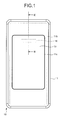
- FIG. 1 is a front view of the mobile phone according to the first embodiment.
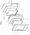
- FIG. 2 is an exploded perspective view of the mobile phone according to the first embodiment.
- a mobile phone 10 includes a front case 11 (housing) and a rear case 12 (housing) provided outside thereof, and the front case 11 and the rear case 12 form a housing unit.
- the front case 11 is formed by molding resin, for example.
- the front case 11 has a flat plate portion 11b which is substantially rectangular.
- the front case 11 has four side faces, in four sides of the flat plate portion 11b, which are arranged perpendicularly to the flat plate portion 11b.
- the front case 11 has an opening 11a formed in substantially center of the flat plate portion 11b.
- the rear case 12 is formed by molding resin, for example.
- the rear case 12 has, similar to the front case 11, a flat plate portion 12b which is substantially rectangular. Similar to the front case 11, the rear case 12 has four side faces, in the four sides of the flat plate portion 12b, which are arranged perpendicularly to the flat plate portion 12b.
- the rear case 12 has an opening for battery storage formed in part of the flat plate portion 12b.
- a battery cover 12a is fitted in the opening for battery storage.
- a cover glass 13 is a transparent plate formed of glass.
- the cover glass 13 is arranged in the opening 11a of the front case 11.
- a surface in the external side of the cover glass 13 is made flush with an outer surface of the flat plate portion 11b.
- the mobile phone 10 according to the present embodiment is provided with the cover glass 13 as a cover member for covering the opening 11a; however, the embodiment is not limited thereto.
- the cover member has only to be a transparent plate member, and therefore a transparent plate member made of, for example, plastic may be used.
- the front case 11, the rear case 12, the battery cover 12a, and the cover glass 13 form the outer surface of the mobile phone 10.
- FIG. 3 is a cross-sectional view of the mobile phone according to the first embodiment in a III-III direction in FIG. 1 .
- a positional relation among the components forming the mobile phone 10 will be explained below with reference to FIG. 2 and FIG. 3 .
- the mobile phone 10 includes an elastic member 19 and a piezoelectric element 16, a touch sensor 15, a double-sided tape 20, a display unit 14, a substrate 17, a battery 18, and the rear case 12, which are arranged inside the housing unit in this order along a thickness direction from the cover glass 13 to the inside of the housing unit (a direction from the front side to the back side in FIG. 1 , hereinafter, called “lamination direction").
- laminate direction a direction from the front side to the back side in FIG. 1
- the touch sensor 15 is a type of operation input units that detect an operation externally input to an operation surface on the outside of the housing. Specifically, the touch sensor 15 has a substantially plate-shaped operation surface (contact surface) with a given area. When an external object comes into contact with part of the contact surface, the touch sensor 15 transmits a predetermined electrical signal corresponding to a position where the external object is in contact with the contact surface to a control unit of the mobile phone 10.
- the touch sensor 15 has a transparent conductive film.
- the touch sensor 15 detects a change in capacitance between the conductive film and the external object.
- the touch sensor 15 detects which part of the contact surface is contacted by the external object based on the detection of the change in capacitance, and transmits the predetermined electrical signal indicating the position where the external object is in contact therewith to the control unit (capacitive system).
- the contact surface of the touch sensor 15 does not need to be directly contacted by the external object. Therefore, even if the cover glass 13 is sandwiched between the contact surface and the external object as in the present embodiment, the touch sensor detects the contact of the external object.
- the touch sensor 15 is laminated on the external side of the housing unit in opposite to a display area 14e side of the display unit 14, and is thereby exposed from the housing unit.
- the touch sensor 15 is directly fixed to the cover glass 13.
- the elastic member 19 is arranged between the touch sensor 15 and the front case 11.
- the display unit 14 is arranged on the housing inner side of the touch sensor 15. The display unit 14 and the touch sensor 15 are adhered to each other by the double-sided tape 20.
- the display unit 14 displays information on the outside of the housing unit via the cover glass 13 and the touch sensor 15.
- the display unit 14 includes a display device 14a and a metal frame 14b.
- the display unit 14 has a flat plate shape.
- the display device 14a is formed of LCD (Liquid Crystal Display), OEL (Organic Electro-Luminescence), or so, and has a display surface 14c for displaying various pieces of information. A portion other than the display surface 14c of the display device 14a is surrounded by the metal frame 14b.
- the metal frame 14b has functions of holding the display device 14a and protecting it from external shock by surrounding the portion other than the display surface 14c of the display device 14a.
- the display unit 14 has a non-display area 14d and the display area 14e on the display surface 14c.
- the non-display area 14d is an area around an outer periphery of the display surface 14c.
- the display area 14e is an area other than the non-display area 14d, which is adjacent to the non-display area 14d, within an area of the display surface 14c.
- the display unit 14 is arranged inside the housing unit such that the display area 14e can be viewed from the outside of the housing unit through the opening 11a.
- the piezoelectric element 16 is arranged on the side of touch sensor 15 in the opposite to the display unit 14.
- the piezoelectric element 16 will be explained in detail later.
- the substrate 17 is a substantially flat-plate shaped component having various semiconductor chips 17a such as a control unit provided on its surface.
- the substrate 17 is arranged inside the housing unit between the display unit 14 and the battery 18 in the lamination direction. Screw holes are formed on four corners of the substrate 17.
- the substrate 17 is fixed to the rear case 12 by inserting screws or pins into the screw holes. Specifically, the substrate 17 is fixed to ribs (not illustrated) provided on the rear case 12 using the screws or the pins.
- the battery 18 is a component that supplies a power to components such as the control unit, the touch sensor 15, and the piezoelectric element 16.
- the battery 18 is arranged inside the housing unit between the battery cover 12a and the substrate 17.
- the battery cover 12a is arranged on the outside of the housing unit so as to cover the opening formed in the rear case 12.
- the battery cover 12a is removable by the user.
- the battery 18 is arranged at a position where it is exposed to the outside when the battery cover 12a is removed from the rear case 12. Therefore, when the battery cover 12a is removed, the user can attach or remove the battery 18.
- the piezoelectric element 16 according to the present embodiment will be explained in detail below with reference to FIG. 1 to FIG. 3 .
- the piezoelectric element 16 has piezo ceramics (piezoelectric element).
- the piezoelectric element 16 is a receiver using mechanical natural resonance phenomenon of the piezo ceramics, and is provided on the housing inner side of the cover glass 13.
- the piezoelectric element 16 is a bar shape (e.g., width 3 mm, length 25 mm, thickness 0.5 mm). As illustrated in FIG. 1 , the piezoelectric element 16 is arranged in a direction in which its long-side direction is along a short-side direction of the cover glass 13 (the short-side direction of the front case 11). The piezoelectric element 16 is arranged on the upper side with respect to the center of the long-side direction of the cover glass 13 (the long-side direction of the front case 11). In addition, the piezoelectric element 16 is provided symmetrically with respect to an imaginary line (III-III line in FIG. 1 ) being parallel to the long-side direction of the front case 11 and passing through the center in the short-side direction of the front case 11.
- the piezoelectric element 16 transmits the vibration of the piezoelectric element generated by using the mechanical natural resonance phenomena to the cover glass 13 to vibrate the cover glass 13.
- the piezoelectric element 16 is a sound output unit that transmits vibration sound to the user by vibrating part of the mobile phone 10 (the cover glass 13 in the present embodiment) to be in contact with the user. In other words, the piezoelectric element 16 transmits the sound transmitted by the vibration to the human body, to allow the user to listen to the sound and music.
- the sound transmitted by the vibration to the human body mentioned here is based on a system of transmission of sound to the user by transmitting the vibration to portions in contact between the piezoelectric element 16 and the human body, specifically, ear cartilage or the like and by vibrating the user body, particularly, cartilage and the like around the ear.
- the vibration generated by the piezoelectric element 16 is transmitted to the user through the human body, for example, the ear cartilage via the cover glass 13, so that the user can listen to the sound output from the mobile phone 10.
- the piezoelectric element 16 may be a fine and thin bar-like member, and therefore it is suitable for implementation thereof into the inner side of the mobile phone 10 such as the cover glass 13.
- the vibration generated by the piezoelectric element 16 is transmitted to the user via only the cover glass 13.
- an amount in which the vibration generated by the piezoelectric element 16 is damped before it is transmitted to the cartilage near the ear of the user can be reduced, which enables efficient transmission of the vibration.
- the piezoelectric element 16 is provided to the cover glass 13, and therefore, as compared with a case where the piezoelectric element 16 is provided on the housing inner side of the flat plate portion 11b or the like, a space inside the housing can be reduced, which enables reduction in size of the mobile phone 10.
- any other member can be arranged in the space on the housing inner side of the flat plate portion 11b, which enables effective use of the space inside the housing.
- the piezoelectric element 16 is provided to the cover glass 13, and therefore, for example, when built therein, the piezoelectric element 16 can be also provided on the cover glass 13 in the process of fixing the display unit 14 and the touch sensor 15 to the cover glass 13, which enables achievement of high efficiency of the built-in operation.
- the piezoelectric element 16 is arranged on the upper side with respect to the center of the long-side direction of the cover glass 13 (long-side direction of the front case 11). This position is near a position where a dynamic spear is generally arranged in the mobile phone having the same structure as that of FIG. 1 and with the dynamic speaker. Therefore, when the user listens to sound on the mobile phone 10, the user has only to press the ear on the same position as the case when the user listens to sound on a mobile phone with the dynamic speaker. This enables the user to listen to the sound on the mobile phone 10 without any discomfort.
- the piezoelectric element 16 is arranged symmetrically with respect to the imaginary line passing through the center in the short-side direction of the front case 11, and the vibration generated from the piezoelectric element 16 is thereby transmitted uniformly to the cover glass 13.
- the cover glass 13 it is possible to suppress the variation in vibration to be transmitted to the user between cases where the user presses the cartilage near the ear on the left side of the cover glass 13 and where the user presses the cartilage on the right side thereof.
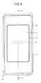
- FIG 4 is a front view of a mobile phone according to the second embodiment.
- FIG 5 is a cross-sectional view of the mobile phone according to the second embodiment in a V-V direction in FIG. 4 .
- explanation of the same portions as these of the first embodiment is omitted, and only portions different from the first embodiment will therefore be explained below.
- the piezoelectric element 16 is provided on the side of the display device 14a in the opposite to the touch sensor 15.
- the piezoelectric element 16 may be in contact with the metal frame 14b or does not have to be in contact therewith.
- the piezoelectric element 16 is arranged in a direction in which its long-side direction is along the short-side direction of the front case 11. As illustrated in FIG 4 , the piezoelectric element 16 is provided symmetrically with respect to an imaginary line (V-V line in FIG. 4 ) being parallel to the long-side direction of the front case 11 and passing through the center in the short-side direction of the front case 11. In addition, as illustrated in FIG 4 , the piezoelectric element 16 is provided symmetrically with respect to an imaginary line being parallel to the short-side direction of the front case 11 and passing through the center in the long-side direction of the front case 11.
- V-V line in FIG. 4 an imaginary line
- the piezoelectric element 16 is provided to the display device 14a (display unit 14), the vibration generated by the piezoelectric element 16 is transmitted over a wide range of the mobile phone 10 via the display unit 14, the touch sensor 15 in contact with the display unit 14, and the cover glass 13. This enables the user to recognize the sound even if the cartilage near the ear is pressed on various positions in the cover glass 13 and the front case 11.
- the space inside of the housing can be reduced as compared with, for example, the case where the piezoelectric element 16 is provided on the housing inner side of the flat plate portion 11b or the case where it is provided on the housing inner side of the cover glass 13, which leads to reduction in size of the mobile phone 10.
- any other member can be arranged in the space on the housing inner side of the flat plate portion 11b, which enables effective use of the space inside the housing.
- the piezoelectric element 16 is arranged symmetrically with respect to the imaginary line passing through the center in the long-side direction or the short-side direction of the front case 11, the vibration generated from the piezoelectric element 16 is thereby transmitted uniformly to the cover glass 13, so that it is possible to reduce the variation in the vibration between the cases where the user presses the cartilage near the ear on a plurality of positions of the cover glass 13.
- FIG 6 is a cross-sectional view of the mobile phone according to the third embodiment.
- FIG 6 is the cross-sectional view of the mobile phone according to the third embodiment when viewed from the same direction as that of the III-III arrows in FIG 1 .
- the explanation of the same portions as these of the first embodiment is omitted, and only portions different from the first embodiment will therefore be explained below.
- the piezoelectric element 16 is provided on the housing inner side of the flat plate portion 11b of the front case 11.
- the piezoelectric element 16 is provided at an end portion of the front case 11 in the long-side direction.
- the front case 11 has a mount portion 11c where the end portion of the cover glass 13 is mounted.
- the mount portion 11c is extended from the flat plate portion 11b, to be located on the housing inner side of with respect to the flat plate portion 11b.
- a surface of the mount portion 11c where the end portion of the cover glass 13 is mounted is parallel to the flat plate portion 11b.
- the piezoelectric element 16 is arranged in a concave portion formed by the mount portion 11c and the side face portion of the front case 11.
- the piezoelectric element 16 is provided to the front case 11.
- the front case 11 is formed of resin.
- the piezoelectric element 16 is provided to the flat plate portion 11b of the front case 11 whose proportion occupied in the area of the front portion of the mobile phone 10 is small. Therefore, as compared with the case where the sound is transmitted to the user via, for example, the glass, the range in which the mobile phone 10 vibrates can be made narrow. Accordingly, the proportion of the vibration generated by the piezoelectric element 16 to be transmitted to an area around the user is small as compared with the proportion thereof being transmitted to the user via the ear cartilage or the like of the user. In other words, the possibility that the sound output from the mobile phone 10 may be heard by someone around can be reduced.
- the piezoelectric element 16 is arranged at the end portion of the front case 11 in the long-side direction. Similar to the first embodiment, this position is near the position where the dynamic speaker is generally arranged in the mobile phone having the same structure as that of FIG. 1 and with the dynamic speaker. Therefore, upon listening to the sound on the mobile phone 10, the user has only to press the ear on the same position as the case when the user listens to the sound on the mobile phone with the dynamic speaker. This enables the user to listen to the sound on the mobile phone 10 without any discomfort.
- FIG. 7 is a cross-sectional view of the mobile phone according to the fourth embodiment.
- FIG 7 is the cross-sectional view of the mobile phone according to the fourth embodiment when viewed from the same direction as that of the III-III arrows in FIG 1 .
- the explanation of the same portions as these of the first embodiment is omitted, and only portions different from the first embodiment will therefore be explained below.
- the mobile phone 10 has a decorative member 30.
- the decorative member 30 is formed of, for example, resin.
- the decorative member 30 is exposed to the outside of the housing through the opening 11a.
- a portion of the decorative member 30 exposed to the outside of the housing is formed to have shapes of characters, figures, or the like.
- the decorative member 30 may be a light guiding member that is formed of light transmissive resin and guides light emitted from a light-emitting element arranged in the mobile phone 10 to the outside of the housing.
- the decorative member 30 has an exposed portion 30a exposed to the outside through the opening 11a and support portions 30b that extend from the exposed portion 30a and support the decorative member 30 inside the housing.
- An exposed surface of the exposed portion 30a is substantially flush with the planes of the flat plate portion 11b and the cover glass 13.
- the support portions 30b are provided in a manner extending from the exposed portion 30a respectively on the upper side and the lower side thereof along the long-side direction of the front case 11.
- An upper support portion 30b is fixed to the housing inner side of the flat plate portion 11b.
- a lower support portion 30b is fixed to the housing inner side of the cover glass 13.
- the piezoelectric element 16 is provided to the face on the housing inner side of the upper support portion 30b of the decorative member 30.
- the piezoelectric element 16 is provided to an area near the end potion of the front case 11 in the long-side direction.
- the piezoelectric element 16 is provided to the decorative member 30 which is a separate component from the front case 11, to thereby transmit the vibration generated by the piezoelectric element 16 to the user via the decorative member 30.
- This enables the range in which the mobile phone 10 vibrates to be reduced as compared with the case where the sound is transmitted to the user via, for example, the glass similar to the third embodiment.
- the proportion of the vibration generated by the piezoelectric element 16 to be transmitted to an area around the user is reduced as compared with the proportion that the vibration is transmitted to the user via the cartilage near the ear of the user. In other words, the possibility that the sound output from the mobile phone 10 may be heard by someone around can be reduced.
- the piezoelectric element 16 may be provided at any one of the positions indicated by dotted line in FIG. 7 . That is, the piezoelectric element 16 may be provided to the lower support portion 30b. Alternatively, the piezoelectric element 16 may be provided to the concave portion formed by the exposed portion 30a and the two support portions 30b. When the piezoelectric element 16 is provided to the concave portion, the space inside the housing can be effectively used as compared with the case where the piezoelectric element 16 is provided to the support portion 30b.
- FIG. 8 is a cross-sectional view of the mobile phone according to the fifth embodiment.
- FIG 8 is the cross-sectional view of the mobile phone according to the fifth embodiment when viewed from the same direction as that of the III-III arrows in FIG 1 .
- the explanation of the same portions as these of the first embodiment is omitted, and only portions different from the first embodiment will therefore be explained below.
- the mobile phone 10 has a space S1 formed in its upper side.
- the flat plate portion 11b has an opening 11d formed on an end portion side of the opening 11a along the long-side direction of the front case 11.
- the space S1 communicates with the outside of the housing through the opening 11d formed on the flat plate portion 11b.
- the piezoelectric element 16 is provided near the opening 11d on the housing inner side of the flat plate portion 11b.
- the piezoelectric element 16 vibrates an area near the opening 11d of the flat plate portion 11b. Furthermore, the vibration generated by the piezoelectric element 16 vibrates the air in the space S1, and the vibration of the air (i.e., sound wave) is transmitted to the outside of the housing through the opening 11d.
- the area of the flat plate portion 11b where the piezoelectric element 16 is provided, the area of the opening 11d, and the volume of the space S1 are adjusted appropriately, and the vibration and the sound wave can thereby be cancelled each other in a predetermined frequency band.
- the vibration and the sound wave can be amplified in a predetermined frequency band based on a principle of superposition.
- the volume of the space S1 appropriately, sound pressure and sound quality of the sound wave can be adjusted.
- the vibration of the flat plate portion 11b is transmitted to the user through the cartilage, and, in some cases, a sound wave passing through the opening 11d is generated and the generated sound wave may be transmitted to an eardrum through a hole of the ear.
- the sound wave passing through the opening 11d is not transmitted to an external space, and therefore cancelling or amplification of the sound waves in the predetermined frequency band is hard to occur.
- the piezoelectric element 16 when the piezoelectric element 16 is provided on the inner side of the housing that faces the opening 11d for example, the sound wave transmitted from the opening 11d to the outside of the housing is transmitted, by diffraction, to a space that is outside of the housing and is situated on the right side of FIG. 8 . Therefore, even when the piezoelectric element 16 is provided on the inner side of the housing that faces the opening 11d, for example, by adjusting the area of the opening 11d and the volume of the space S1 appropriately, the vibration and the sound wave can be cancelled each other in the predetermined frequency band. Moreover, the vibration and the sound wave can be amplified in the predetermined frequency band based on the principle of superposition.
- FIG. 9 is a cross-sectional view of the front case 11 of the mobile phone according to the sixth embodiment.
- the explanation of the same portions as these of the first embodiment is omitted, and only portions different from the first embodiment will therefore be explained below.
- the substrate 17 is a multilayer substrate, which is formed of glass epoxy resin.
- the glass epoxy resin is formed by laminating a base material (glass fabric base material) formed of, for example, a glass fabric layer on top of another over the multilayer, impregnating the epoxy resin being thermosetting resin, and subjecting the impregnated epoxy resin to a heat treatment to be hardened.
- the substrate 17 is fixed to the front case 11, and includes a base layer 110, an intermediate layer 111, and a cover layer 112.
- the piezoelectric element 16 is provided between the base layer 110 and the cover layer 112.
- the piezoelectric element 16 is provided to a portion in which part of the intermediate layer 111 is not formed.
- the intermediate layer 111 plays a role of a spacer for providing the piezoelectric element 16 inside the front case 11.
- An electrode 160 is arranged between the intermediate layer 111 and the cover layer 112.
- the electrode 160 is coupled to the piezoelectric element 16.
- the electrode 160 which is an inner layer of the substrate 17 is coupled to a conductive line (not illustrated) to supply a power to the piezoelectric element 16.
- the piezoelectric element 16 is provided inside the substrate 17.
- the substrate 17 is fixed to the front case 11.
- the piezoelectric element 16 is arranged in a position near the outer surface of the front case 11, and therefore the vibration generated by the piezoelectric element 16 is appropriately transmitted to the user.
- the user can appropriately listen to the sound output from the mobile phone 10.
- the piezoelectric element 16 is provided inside the substrate 17, and therefore a process of incorporating the piezoelectric element 16 inside the housing is not needed. Moreover, the space inside the housing can be efficiently used as compare with the case where the piezoelectric element 16 is arranged inside the housing.
- the space is provided between the layers of the substrate 17 and the piezoelectric element 16 is provided inside the substrate 17.
- the piezoelectric element 16 may be embedded inside the front case 11 by insert molding.
- the front case 11 is molded by two-color molding, it may be structured that the piezoelectric element 16 is put in a mold after a primary molding process, then a secondary molding process is performed, and the piezoelectric element 16 is thereby embedded inside the front case 11.
- the piezoelectric element 16 is arranged at a position near the outer surface of the front case 11, and therefore the vibration generated by the piezoelectric element 16 is appropriately transmitted to the user. As a result, the user can appropriately listen to the sound output from the mobile phone 10.
- FIG. 10 and FIG. 11 are cross-sectional views of the mobile phone according to the seventh embodiment.
- FIG. 10 and FIG. 11 are the cross-sectional views of the mobile phone according to the seventh embodiment when viewed from the same direction as that of the III-III arrows in FIG 1 .
- the explanation of the same portions as these of the first embodiment is omitted, and only portions different from the first embodiment will therefore be explained below.
- an opening 11e and an opening 11f are formed on the front case 11.
- the piezoelectric element 16 is arranged inside the opening 11e.
- a protrusion 40a of a switch 40, explained later, is arranged in the opening 11f.
- Holes 11g and 11h are formed on the front case 11.
- the cross section of the holes 11g and 11h is a circle, and the hole 11h is formed on the outer side of the housing with respect to the hole 11g.
- the holes 11g and 11h communicate with each other through a through hole.
- An engagement portion 162a of a leg portion 162, explained later, is inserted in the holes 11g and 11h.
- a face on the housing inner side of the piezoelectric element 16 is fixed to a vibrating plate 161.
- the vibrating plate 161 has substantially the same size as that of the piezoelectric element 16, but its length in the long-side direction of the front case 11 is longer than the piezoelectric element 16.
- the leg portion 162 is provided at each end of the vibrating plate 161 along the long-side direction of the front case 11.
- the leg portion 162 protrudes from the vibrating plate 161 toward the housing in the thickness direction thereof.
- the engagement portion 162a is provided at the end of the leg portion 162.
- the cross section of the engagement portion 162a is substantially circle, and is inserted in the hole 11g or 11h formed on the front case 11 to be engaged therein.
- the mobile phone 10 according to the seventh embodiment has also the switch 40.
- the switch 40 has the protrusion 40a and an edge 40b.
- the protrusion 40a of the switch 40 is exposed to the outside of the housing through the opening 11f formed on the front case 11.
- An edge surface of the protrusion 40a protrudes more than the surface of the front case 11.
- the edge 40b is fixed to the upper leg portion 162.
- the switch 40 moves the vibrating plate 161, as will be described now, between a first position in which the piezoelectric element 16 comes in contact with the front case 11 to vibrate the front case 11 and a second position which is on the inner side of the front case 11 than the first position and in which the sound generated by the vibrating plate 161 that vibrates together with the piezoelectric element 16 can be output from the opening 11e.
- the piezoelectric element 16 is in contact with the inner side of the front case 11. At this time, no space is formed between the piezoelectric element 16 and the inner side of the front case 11. In addition, the engagement portion 162a of the leg portion 162 is engaged in the hole 11h. Because the piezoelectric element 16 is in contact with the front case 11, when the piezoelectric element 16 vibrates, then the front case 11 in contact with the piezoelectric element 16 also vibrates. The user brings part of the front case 11 into contact with the cartilage near the ear in this state, and the vibration generated by the piezoelectric element 16 thereby reaches the user's body such as the ear cartilage via the front case 11. This enables the user to listen to the sound (vibration sound) made by the vibration output from the mobile phone 10.
- the piezoelectric element 16, the vibrating plate 161, the leg portions 162, and the switch 40 are positioned on the inner side (right direction in the figure) along the thickness direction of the housing.
- a space S2 is formed between the piezoelectric element 16 and the inner face of the front case 11.
- the engagement portion 162a of the leg portion 162 is engaged in the hole 11g.
- the piezoelectric element 16 is apart from the front case 11, when the piezoelectric element 16 vibrates, then the vibrating plate 161 in contact with the piezoelectric element 16 vibrates.
- the piezoelectric element 16 and the vibrating plate 161 vibrate, which causes the air in the space S2 to vibrate, and the vibration as a sound wave is transmitted to the outside of the housing through the opening 11e formed on the front case 11.
- the user moves the protrusion 40a of the switch 40 along the thickness direction of the housing (horizontal direction in the figure), so that the mobile phone 10 can be switched between the state illustrated in FIG. 10 and the state illustrated in FIG. 11 .
- the switch 40 by operating the switch 40, the user can select the state illustrated in FIG. 10 when he/she wants to listen to the sound from the mobile phone 10 by the vibration sound, and can select the state illustrated in FIG. 11 when the user wants to listen to the sound from the mobile phone 10 in the similar manner to the case in which the dynamic speaker is used.
- the mobile phones 10 according to the first to the seventh embodiments of the present invention has been explained so far with reference to the drawings.
- the mobile phone 10 according to each embodiment of the present invention has the piezoelectric element 16, and the piezoelectric element 16 transmits sound to the human body by the vibration sound, to allow the user to listen to sound and music. Therefore, the mobile phone 10 that transmits the sound using the piezoelectric element 16 does not need to form an opening for sound transmission on the housing, unlike the mobile phone that includes the dynamic speaker. Thus, waterproof and dustproof properties of the mobile phone 10 are ensured.
- the mobile phone 10 according to each embodiment of the present invention transmits the sound to the human body by the vibration sound, and is therefore insulated from the influence of ambient sound.
- the mobile phones 10 according to the first to the seventh embodiments of the present invention has been explained; however, the embodiment is not limited thereto.
- the mobile phone 10 does not have to have the touch sensor 15.
- the position where the piezoelectric element 16 is provided is not necessarily the position explained above as long as a portion of the mobile phone in contact with the cartilage near the user's ear can be vibrated.
- the piezoelectric element 16 may be provided at an end portion of the cover glass 13 in the horizontal direction.
- the mechanism for moving the piezoelectric element is not limited to the switch 40 illustrated in FIG. 10 and FIG. 11 . It could be any mechanism as long as the piezoelectric element can be moved between a position where the piezoelectric element is in close contact with the front case and a position where a space is formed between the piezoelectric element and the front case.
- the mobile phone 10 has a control unit including a processor.
- the control unit applies a predetermined electrical signal (voltage according to a sound signal) to the piezoelectric element 16.
- the voltage that the control unit applies to the piezoelectric element 16 may be, for example, ⁇ 15 V which is higher than ⁇ 5 V being a voltage applied to a so-called panel speaker in order for sound transmission using air-conducted sound instead of vibration sound.
- How much applied voltage is to be used can be adjusted appropriately according to fixing strength with respect to the housing of the panel or the support member or according to performance of the piezoelectric element 16.
- the control unit applies the electrical signal to the piezoelectric element 16
- the piezoelectric element 16 elongates/contracts or bends in the long-side direction.
- the panel provided with the piezoelectric element 16 deforms according to the elongation/contraction or the bending of the piezoelectric element 16, and the panel vibrates. Therefore, the panel generates air-conducted sound and also generates, when the user presses part of his/her body (e.g., external ear cartilage) on the panel, vibration sound via the part of the body.
- part of his/her body e.g., external ear cartilage
- control unit can apply the electrical signal corresponding to the sound signal according to the voice of the other person on the phone to the piezoelectric element 16, and generate the air-conducted sound and the vibration sound corresponding to the sound signal.
- the sound signal may be those according to a ring tone or to musical composition including music, and the like.
- the sound signal according to the electrical signal may be those based on music data stored in an internal memory of the electronic device or may be those in which music data stored in an external server or the like is reproduced via a network.
- the panel preferably vibrates not only an attachment area where the piezoelectric element 16 is attached but also an area apart from the attachment area.
- the panel has a plurality of locations that vibrate in a direction of intersecting with a principal surface of the panel in the vibrating area, and a value of amplitude of the vibration changes from a plus value to a minus value with time or changes inversely in each of the locations.
- the panel vibrates in such a manner that a portion in which amplitude of the vibration is relatively large and a portion in which amplitude of the vibration is relatively small are distributed randomly or periodically over a seemingly and substantially whole panel at a certain moment. In other words, vibrations of a plurality of waves are detected over the whole panel.
- the voltage that the control unit applies to the piezoelectric element 16 may be ⁇ 15 V. Therefore, the user can listen to the sound by pressing the ear on an area away from the attachment area of the panel.
- the panel (e.g., cover glass 13) may be substantially the same size as that of the user's ear.
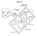
- the panel may be larger in size than the user's ear, as illustrated in FIG. 12 .
- ambient sound noise
- the panel has only to vibrate in an area wider than an area having a length corresponding to a distance from inferior crus of antihelix (inferior antihelix crus) to antitragus and a width corresponding to a distance from tragus to the antihelix.
- the panel is preferably structured so that an area having a length corresponding to a distance from a site near superior crus of antihelix (superior antihelix crus) in helix to earlobe and a width corresponding to a distance from the tragus to a site near the antihelix in the helix vibrates.
- the area having the length and the width may be a rectangular area, or may be an elliptical area in which the length is its major axis and the width is its minor axis.
- An average ear size of Japanese can be learned by referring to Japanese Body Size Database (1992 to 1994) created by Research Institute of Human Engineering for Quality Life (HQL), or the like. If the panel is larger than the average ear size of Japanese, then the panel is considered substantially large enough to cover entire ears of people in other countries.
- the mobile phone 10 is capable of transmitting the air-conducted sound and the human-body vibration sound via part of the user's body (e.g., external ear cartilage) to the user by the vibration of the panel. Therefore, when a sound of the volume equivalent to that of a conventional dynamic receiver is to be output, less sound is transmitted by air vibration due to the vibration of the panel to an area around the mobile phone 10 as compared with that of the dynamic receiver. Therefore, it is suitable for the case in which the user listens to, for example, a recorded message on trains and the like.
- the mobile phone 10 transmits the human-body vibration sound by the vibration of the panel, even if the user wears an earphone or a headphone, the user can listen to the sound via the earphone or the headphone and part of the body by contacting the mobile phone 10 therewith.
- the mobile phone 10 transmits the sound to the user by the vibration of the panel. Therefore, when the mobile phone 10 has no separate dynamic receiver, there is no need to form an opening (sound releasing port) for sound transmission, thus simplifying a waterproof structure of the mobile phone 10.
- the sound releasing port is preferably sealed by an air-permeable but liquid non-permeable member.
- the air-permeable but liquid non-permeable member is, for example, GORE-TEX®.
- FIG. 13 is a cross-sectional view of the mobile phone when viewed from the same direction as that of the III-III arrows in FIG 1 .
- the elastic member 19, the double-sided tape 20, and the display unit 14 are laminated in this order along the lamination direction from the cover glass 13.
- the piezoelectric element 16 is fixed to a portion where the elastic member 19 is not provided within the face on the housing inner side of the cover glass 13.
- the piezoelectric element 16 transmits the vibration of the piezoelectric element generated using the mechanical natural resonance phenomenon to the cover glass 13 to vibrate the cover glass 13.
- FIG. 13 represents an example that the piezoelectric element 16 is fixed to the cover glass 13; however, the piezoelectric element 16 may be fixed to any other portion as explained in the second to the seventh embodiments.
- the piezoelectric element used for the mobile phone 10 may be a bimorph type, a mono-morph type, or a unimorph type of a flat plate made of, for example, lead zirconate titanate (PZT). If it is the bimorph type, a bimorph in which ceramics having about 10 layers to 30 layers and a parallel plate electrode are alternately laminated on top of another is preferably used.
- PZT lead zirconate titanate
Landscapes
- Engineering & Computer Science (AREA)
- Signal Processing (AREA)
- Telephone Set Structure (AREA)
- Piezo-Electric Transducers For Audible Bands (AREA)
- Details Of Audible-Bandwidth Transducers (AREA)
Abstract
Description
- The present invention relates to a mobile electronic device. More particularly, the present invention relates to a mobile electronic device that applies a predetermined electrical signal (sound signal) to a piezoelectric element to vibrate a panel and transmits the vibration of the panel to a human body, thus transmitting vibration sound to a user.
-
Patent Literature 1 describes a device, as an electronic device such as a mobile phone, that transmits air-conducted sound and bone-conducted sound to a user.Patent Literature 1 also describes that the air-conducted sound is sound transmitted to the auditory nerve of the user in such a manner that vibration of air caused by vibration of an object is transmitted to an eardrum through an ear canal to vibrate the eardrum. In addition,Patent Literature 1 describes that the bone-conducted sound (vibration sound) is sound transmitted to the auditory nerve of the user via part of a user's body (e.g., external ear cartilage) in contact with a vibrating object. - Patent Literature 2 describes a speaker known as one that transmits sound to a human body by vibration sound. The speaker transmits the vibration generated by a piezoelectric element arranged in a case to a user via a contact for transmitting vibration energy and via a contact pad that is attached to the case and comes in contact with, for example, cartilage around a user's ear.
-
- Patent Literature 1: Japanese Patent Application Laid-open No.
2005-348193 - Patent Literature 2: Japanese Patent Application Laid-open No.
2008-148086 - Incidentally, when the piezoelectric element as described in
Patent Literature 1 and Patent Literature 2 is used as a sound output unit of a mobile electronic device such as a mobile phone, a positional relation between the piezoelectric element and the other components arranged in the mobile electronic device, and the like, is preferably considered to appropriately transmit sound to the user. - An object of the present invention is to provide a mobile electronic device capable of appropriately transmitting vibration sound to the user.
- According to the invention, a mobile electronic device includes: a housing; and a piezoelectric element. The piezoelectric element vibrates a portion in contact with a user in the mobile electronic device and transmits vibration sound to the user.
- According to the invention, the mobile electronic device may be configured such that the housing has an opening formed therein, the mobile electronic device further includes: a cover member fitted in the opening; and a display unit arranged inside of the housing so that a display area is visible from outside of the housing through the cover member, and the piezoelectric element is attached to the cover member.
- According to the invention, the mobile electronic device may further include a touch panel laminated between the cover member and the display unit.
- According to the invention, the mobile electronic device may be configured such that the housing has an opening formed therein, the mobile electronic device further includes a display unit arranged inside of the housing so that a display area is visible from outside of the housing through the opening, and the piezoelectric element is attached to the display unit.
- According to the invention, the mobile electronic device may further include a touch panel that faces the display area of the display unit and is laminated on an outer side thereof in the housing.
- According to the invention, the mobile electronic device may be configured such that the housing has an opening formed therein, the mobile electronic device further includes a decorative member that is extended from inside of the housing to outside of the housing through the opening, and the piezoelectric element is attached to the decorative member.
- According to the invention, the mobile electronic device may be configured such that he piezoelectric element is fixed to an inner face of the housing.
- According to the invention, the mobile electronic device may be configured such that the housing has a substantially rectangular flat plate portion, and the piezoelectric element is a bar shape, and is arranged so that a long-side direction thereof is along a short-side direction of the flat plate portion and so that a center thereof in the long-side direction coincides with a center in the short-side direction of the flat plate portion.
- According to the invention, the mobile electronic device may be configured such that a circuit substrate is arranged inside of the housing, and the circuit substrate is a multilayer substrate that includes an electrode layer inside of the circuit substrate, the piezoelectric element is provided inside of the multilayer substrate, and the electrode layer is electrically coupled to the piezoelectric element.
- According to the invention, the mobile electronic device may be configured such that at least part of the piezoelectric element is embedded in the housing.
- According to the invention, the mobile electronic device may be configured such that the housing is formed of resin, and the piezoelectric element is embedded in the housing by insert molding.
- According to the invention, the mobile electronic device may be configured such that the housing has an opening formed therein, the piezoelectric element is arranged near the opening, and a first sound transmitted from the vibrating housing to the user and a second sound that is sound generated by the vibration of the piezoelectric element and is transmitted to the user through the opening are cancelled each other in a proportion according to a frequency band.
- According to the invention, the mobile electronic device may be configured such that the housing has an opening formed therein, and at least part of a frequency component of a first sound generated in a portion of the housing vibrated by the piezoelectric element in contact with the user is reduced by a second sound generated inside of the housing by the vibration of the piezoelectric element and output from the opening.
- According to the invention, the mobile electronic device may be configured such that an area where, upon contact with a body of the user, the vibration can be transmitted to the body is same as an ear of the user or is larger than the ear.
- According to the invention, a mobile electronic device incudes: a housing; and a piezoelectric element. The piezoelectric element vibrates a portion in contact with a user in the mobile electronic device and transmits air-conducted sound and vibration sound to the user.
- According to the present invention, it is possible to provide a mobile electronic device capable of appropriately transmitting the sound to the user by vibration sound.
-
-
FIG. 1 is a front view of a mobile phone according to a first embodiment. -
FIG. 2 is an exploded perspective view of the mobile phone according to the first embodiment. -
FIG. 3 is a cross-sectional view of the mobile phone according to the first embodiment in a III-III direction inFIG. 1 . -
FIG. 4 is a front view of a mobile phone according to a second embodiment. -
FIG. 5 is a cross-sectional view of the mobile phone according to the second embodiment in a V-V direction inFIG. 4 . -
FIG. 6 is a cross-sectional view of a mobile phone according to a third embodiment. -
FIG. 7 is a cross-sectional view of a mobile phone according to a fourth embodiment. -
FIG. 8 is a cross-sectional view of a mobile phone according to a fifth embodiment. -
FIG. 9 is a cross-sectional view of a housing of a mobile phone according to a sixth embodiment. -
FIG. 10 is a cross-sectional view of a mobile phone according to a seventh embodiment. -
FIG. 11 is a cross-sectional view of the mobile phone according to the seventh embodiment. -
FIG. 12 is a schematic diagram illustrating a relation between a mobile phone according to a modification of the present invention and a human ear. -
FIG. 13 is a cross-sectional view of a mobile phone according to another modification of the present invention. - A mobile phone being an example of a mobile electronic device according to a first embodiment of the present invention will be explained in detail below with reference to the accompanying drawings. The present invention, however, is not limited by the following explanation. In addition, the components in the explanation below include those which can be easily conceived by persons skilled in the art, those which are substantially identical thereto, and those which are in a scope of so-called equivalents. In the following, a mobile phone is explained as an example of the mobile electronic device; however, a target to which the present invention is applied is not limited to the mobile phone. Therefore, the present invention can be applied to various mobile electronic devices having a function to allow a user to listen to sound by bringing the housing thereof close to his/her ear, such as PHS (Personal Handy-phone System), PDA, and gaming devices.
-
FIG. 1 is a front view of the mobile phone according to the first embodiment.FIG. 2 is an exploded perspective view of the mobile phone according to the first embodiment. Amobile phone 10 includes a front case 11 (housing) and a rear case 12 (housing) provided outside thereof, and thefront case 11 and therear case 12 form a housing unit. - The
front case 11 is formed by molding resin, for example. Thefront case 11 has aflat plate portion 11b which is substantially rectangular. Thefront case 11 has four side faces, in four sides of theflat plate portion 11b, which are arranged perpendicularly to theflat plate portion 11b. Thefront case 11 has an opening 11a formed in substantially center of theflat plate portion 11b. - The
rear case 12 is formed by molding resin, for example. Therear case 12 has, similar to thefront case 11, aflat plate portion 12b which is substantially rectangular. Similar to thefront case 11, therear case 12 has four side faces, in the four sides of theflat plate portion 12b, which are arranged perpendicularly to theflat plate portion 12b. Therear case 12 has an opening for battery storage formed in part of theflat plate portion 12b. Abattery cover 12a is fitted in the opening for battery storage. - A
cover glass 13 is a transparent plate formed of glass. Thecover glass 13 is arranged in theopening 11a of thefront case 11. A surface in the external side of thecover glass 13 is made flush with an outer surface of theflat plate portion 11b. Themobile phone 10 according to the present embodiment is provided with thecover glass 13 as a cover member for covering theopening 11a; however, the embodiment is not limited thereto. The cover member has only to be a transparent plate member, and therefore a transparent plate member made of, for example, plastic may be used. - The
front case 11, therear case 12, thebattery cover 12a, and thecover glass 13 form the outer surface of themobile phone 10. -
FIG. 3 is a cross-sectional view of the mobile phone according to the first embodiment in a III-III direction inFIG. 1 . A positional relation among the components forming themobile phone 10 will be explained below with reference toFIG. 2 andFIG. 3 . - The
mobile phone 10 includes anelastic member 19 and apiezoelectric element 16, atouch sensor 15, a double-sided tape 20, adisplay unit 14, asubstrate 17, abattery 18, and therear case 12, which are arranged inside the housing unit in this order along a thickness direction from thecover glass 13 to the inside of the housing unit (a direction from the front side to the back side inFIG. 1 , hereinafter, called "lamination direction"). The components will be explained in detail below. - The
touch sensor 15 is a type of operation input units that detect an operation externally input to an operation surface on the outside of the housing. Specifically, thetouch sensor 15 has a substantially plate-shaped operation surface (contact surface) with a given area. When an external object comes into contact with part of the contact surface, thetouch sensor 15 transmits a predetermined electrical signal corresponding to a position where the external object is in contact with the contact surface to a control unit of themobile phone 10. - More specifically, the
touch sensor 15 has a transparent conductive film. When contacted by the external object such as a human finger, thetouch sensor 15 detects a change in capacitance between the conductive film and the external object. Thetouch sensor 15 detects which part of the contact surface is contacted by the external object based on the detection of the change in capacitance, and transmits the predetermined electrical signal indicating the position where the external object is in contact therewith to the control unit (capacitive system). - When the capacitive system is adopted, the contact surface of the
touch sensor 15 does not need to be directly contacted by the external object. Therefore, even if thecover glass 13 is sandwiched between the contact surface and the external object as in the present embodiment, the touch sensor detects the contact of the external object. Thetouch sensor 15 is laminated on the external side of the housing unit in opposite to adisplay area 14e side of thedisplay unit 14, and is thereby exposed from the housing unit. - Moreover, the
touch sensor 15 is directly fixed to thecover glass 13. Theelastic member 19 is arranged between thetouch sensor 15 and thefront case 11. Thedisplay unit 14 is arranged on the housing inner side of thetouch sensor 15. Thedisplay unit 14 and thetouch sensor 15 are adhered to each other by the double-sided tape 20. - The
display unit 14 displays information on the outside of the housing unit via thecover glass 13 and thetouch sensor 15. Thedisplay unit 14 includes adisplay device 14a and ametal frame 14b. Thedisplay unit 14 has a flat plate shape. - The
display device 14a is formed of LCD (Liquid Crystal Display), OEL (Organic Electro-Luminescence), or so, and has adisplay surface 14c for displaying various pieces of information. A portion other than thedisplay surface 14c of thedisplay device 14a is surrounded by themetal frame 14b. Themetal frame 14b has functions of holding thedisplay device 14a and protecting it from external shock by surrounding the portion other than thedisplay surface 14c of thedisplay device 14a. - The
display unit 14 has anon-display area 14d and thedisplay area 14e on thedisplay surface 14c. Thenon-display area 14d is an area around an outer periphery of thedisplay surface 14c. Thedisplay area 14e is an area other than thenon-display area 14d, which is adjacent to thenon-display area 14d, within an area of thedisplay surface 14c. Thedisplay unit 14 is arranged inside the housing unit such that thedisplay area 14e can be viewed from the outside of the housing unit through theopening 11a. - The
piezoelectric element 16 is arranged on the side oftouch sensor 15 in the opposite to thedisplay unit 14. Thepiezoelectric element 16 will be explained in detail later. - The
substrate 17 is a substantially flat-plate shaped component havingvarious semiconductor chips 17a such as a control unit provided on its surface. Thesubstrate 17 is arranged inside the housing unit between thedisplay unit 14 and thebattery 18 in the lamination direction. Screw holes are formed on four corners of thesubstrate 17. Thesubstrate 17 is fixed to therear case 12 by inserting screws or pins into the screw holes. Specifically, thesubstrate 17 is fixed to ribs (not illustrated) provided on therear case 12 using the screws or the pins. - The
battery 18 is a component that supplies a power to components such as the control unit, thetouch sensor 15, and thepiezoelectric element 16. Thebattery 18 is arranged inside the housing unit between thebattery cover 12a and thesubstrate 17. Thebattery cover 12a is arranged on the outside of the housing unit so as to cover the opening formed in therear case 12. Thebattery cover 12a is removable by the user. Thebattery 18 is arranged at a position where it is exposed to the outside when thebattery cover 12a is removed from therear case 12. Therefore, when thebattery cover 12a is removed, the user can attach or remove thebattery 18. - The
piezoelectric element 16 according to the present embodiment will be explained in detail below with reference toFIG. 1 to FIG. 3 . - The
piezoelectric element 16 has piezo ceramics (piezoelectric element). Thepiezoelectric element 16 is a receiver using mechanical natural resonance phenomenon of the piezo ceramics, and is provided on the housing inner side of thecover glass 13. Thepiezoelectric element 16 is a bar shape (e.g., width 3 mm, length 25 mm, thickness 0.5 mm). As illustrated inFIG. 1 , thepiezoelectric element 16 is arranged in a direction in which its long-side direction is along a short-side direction of the cover glass 13 (the short-side direction of the front case 11). Thepiezoelectric element 16 is arranged on the upper side with respect to the center of the long-side direction of the cover glass 13 (the long-side direction of the front case 11). In addition, thepiezoelectric element 16 is provided symmetrically with respect to an imaginary line (III-III line inFIG. 1 ) being parallel to the long-side direction of thefront case 11 and passing through the center in the short-side direction of thefront case 11. - The
piezoelectric element 16 transmits the vibration of the piezoelectric element generated by using the mechanical natural resonance phenomena to thecover glass 13 to vibrate thecover glass 13. Thepiezoelectric element 16 is a sound output unit that transmits vibration sound to the user by vibrating part of the mobile phone 10 (thecover glass 13 in the present embodiment) to be in contact with the user. In other words, thepiezoelectric element 16 transmits the sound transmitted by the vibration to the human body, to allow the user to listen to the sound and music. The sound transmitted by the vibration to the human body mentioned here is based on a system of transmission of sound to the user by transmitting the vibration to portions in contact between thepiezoelectric element 16 and the human body, specifically, ear cartilage or the like and by vibrating the user body, particularly, cartilage and the like around the ear. Thus, when the user brings part of thecover glass 13 into contact with the cartilage near the ear, the vibration generated by thepiezoelectric element 16 is transmitted to the user through the human body, for example, the ear cartilage via thecover glass 13, so that the user can listen to the sound output from themobile phone 10. - The
piezoelectric element 16 may be a fine and thin bar-like member, and therefore it is suitable for implementation thereof into the inner side of themobile phone 10 such as thecover glass 13. In the first embodiment, based on the structure in which thepiezoelectric element 16 is provided to thecover glass 13, the vibration generated by thepiezoelectric element 16 is transmitted to the user via only thecover glass 13. Thus, an amount in which the vibration generated by thepiezoelectric element 16 is damped before it is transmitted to the cartilage near the ear of the user can be reduced, which enables efficient transmission of the vibration. - In the first embodiment, the
piezoelectric element 16 is provided to thecover glass 13, and therefore, as compared with a case where thepiezoelectric element 16 is provided on the housing inner side of theflat plate portion 11b or the like, a space inside the housing can be reduced, which enables reduction in size of themobile phone 10. Alternatively, for example, as compared with the case where thepiezoelectric element 16 is provided on the housing inner side of theflat plate portion 11b, any other member can be arranged in the space on the housing inner side of theflat plate portion 11b, which enables effective use of the space inside the housing. - In the first embodiment, the
piezoelectric element 16 is provided to thecover glass 13, and therefore, for example, when built therein, thepiezoelectric element 16 can be also provided on thecover glass 13 in the process of fixing thedisplay unit 14 and thetouch sensor 15 to thecover glass 13, which enables achievement of high efficiency of the built-in operation. - In the first embodiment, the
piezoelectric element 16 is arranged on the upper side with respect to the center of the long-side direction of the cover glass 13 (long-side direction of the front case 11). This position is near a position where a dynamic spear is generally arranged in the mobile phone having the same structure as that ofFIG. 1 and with the dynamic speaker. Therefore, when the user listens to sound on themobile phone 10, the user has only to press the ear on the same position as the case when the user listens to sound on a mobile phone with the dynamic speaker. This enables the user to listen to the sound on themobile phone 10 without any discomfort. - In the first embodiment, the
piezoelectric element 16 is arranged symmetrically with respect to the imaginary line passing through the center in the short-side direction of thefront case 11, and the vibration generated from thepiezoelectric element 16 is thereby transmitted uniformly to thecover glass 13. Thus, it is possible to suppress the variation in vibration to be transmitted to the user between cases where the user presses the cartilage near the ear on the left side of thecover glass 13 and where the user presses the cartilage on the right side thereof. - The
mobile phone 10 according to a second embodiment of the present invention will be explained below with reference toFig. 4 andFIG. 5 .FIG 4 is a front view of a mobile phone according to the second embodiment.FIG 5 is a cross-sectional view of the mobile phone according to the second embodiment in a V-V direction inFIG. 4 . Hereinafter, explanation of the same portions as these of the first embodiment is omitted, and only portions different from the first embodiment will therefore be explained below. - As illustrated in
FIG. 5 , in the second embodiment, thepiezoelectric element 16 is provided on the side of thedisplay device 14a in the opposite to thetouch sensor 15. Thepiezoelectric element 16 may be in contact with themetal frame 14b or does not have to be in contact therewith. - As illustrated in
FIG. 4 , thepiezoelectric element 16 is arranged in a direction in which its long-side direction is along the short-side direction of thefront case 11. As illustrated inFIG 4 , thepiezoelectric element 16 is provided symmetrically with respect to an imaginary line (V-V line inFIG. 4 ) being parallel to the long-side direction of thefront case 11 and passing through the center in the short-side direction of thefront case 11. In addition, as illustrated inFIG 4 , thepiezoelectric element 16 is provided symmetrically with respect to an imaginary line being parallel to the short-side direction of thefront case 11 and passing through the center in the long-side direction of thefront case 11. - Thus, in the second embodiment, because the
piezoelectric element 16 is provided to thedisplay device 14a (display unit 14), the vibration generated by thepiezoelectric element 16 is transmitted over a wide range of themobile phone 10 via thedisplay unit 14, thetouch sensor 15 in contact with thedisplay unit 14, and thecover glass 13. This enables the user to recognize the sound even if the cartilage near the ear is pressed on various positions in thecover glass 13 and thefront case 11. - In the second embodiment, because the
piezoelectric element 16 is provided to thedisplay device 14a (display unit 14), the space inside of the housing can be reduced as compared with, for example, the case where thepiezoelectric element 16 is provided on the housing inner side of theflat plate portion 11b or the case where it is provided on the housing inner side of thecover glass 13, which leads to reduction in size of themobile phone 10. Alternatively, for example, as compared with the case where thepiezoelectric element 16 is provided on the housing inner side of theflat plate portion 11b or the case where it is provided on the housing inner side of thecover glass 13, any other member can be arranged in the space on the housing inner side of theflat plate portion 11b, which enables effective use of the space inside the housing. - In the second embodiment, the
piezoelectric element 16 is arranged symmetrically with respect to the imaginary line passing through the center in the long-side direction or the short-side direction of thefront case 11, the vibration generated from thepiezoelectric element 16 is thereby transmitted uniformly to thecover glass 13, so that it is possible to reduce the variation in the vibration between the cases where the user presses the cartilage near the ear on a plurality of positions of thecover glass 13. - The
mobile phone 10 according to a third embodiment of the present invention will be explained below with reference toFIG 6. FIG 6 is a cross-sectional view of the mobile phone according to the third embodiment.FIG 6 is the cross-sectional view of the mobile phone according to the third embodiment when viewed from the same direction as that of the III-III arrows inFIG 1 . Hereinafter, the explanation of the same portions as these of the first embodiment is omitted, and only portions different from the first embodiment will therefore be explained below. - As illustrated in
FIG. 6 , in the third embodiment, thepiezoelectric element 16 is provided on the housing inner side of theflat plate portion 11b of thefront case 11. Thepiezoelectric element 16 is provided at an end portion of thefront case 11 in the long-side direction. - In the third embodiment, the
front case 11 has amount portion 11c where the end portion of thecover glass 13 is mounted. Themount portion 11c is extended from theflat plate portion 11b, to be located on the housing inner side of with respect to theflat plate portion 11b. A surface of themount portion 11c where the end portion of thecover glass 13 is mounted is parallel to theflat plate portion 11b. Thepiezoelectric element 16 is arranged in a concave portion formed by themount portion 11c and the side face portion of thefront case 11. - Thus, in the third embodiment, the
piezoelectric element 16 is provided to thefront case 11. Thefront case 11 is formed of resin. - In the third embodiment, the
piezoelectric element 16 is provided to theflat plate portion 11b of thefront case 11 whose proportion occupied in the area of the front portion of themobile phone 10 is small. Therefore, as compared with the case where the sound is transmitted to the user via, for example, the glass, the range in which themobile phone 10 vibrates can be made narrow. Accordingly, the proportion of the vibration generated by thepiezoelectric element 16 to be transmitted to an area around the user is small as compared with the proportion thereof being transmitted to the user via the ear cartilage or the like of the user. In other words, the possibility that the sound output from themobile phone 10 may be heard by someone around can be reduced. - In the third embodiment, the
piezoelectric element 16 is arranged at the end portion of thefront case 11 in the long-side direction. Similar to the first embodiment, this position is near the position where the dynamic speaker is generally arranged in the mobile phone having the same structure as that ofFIG. 1 and with the dynamic speaker. Therefore, upon listening to the sound on themobile phone 10, the user has only to press the ear on the same position as the case when the user listens to the sound on the mobile phone with the dynamic speaker. This enables the user to listen to the sound on themobile phone 10 without any discomfort. - The
mobile phone 10 according to a fourth embodiment of the present invention will be explained below with reference toFIG. 7. FIG. 7 is a cross-sectional view of the mobile phone according to the fourth embodiment.FIG 7 is the cross-sectional view of the mobile phone according to the fourth embodiment when viewed from the same direction as that of the III-III arrows inFIG 1 . Hereinafter, the explanation of the same portions as these of the first embodiment is omitted, and only portions different from the first embodiment will therefore be explained below. - As illustrated in
FIG. 7 , themobile phone 10 according to the fourth embodiment has adecorative member 30. Thedecorative member 30 is formed of, for example, resin. Thedecorative member 30 is exposed to the outside of the housing through theopening 11a. A portion of thedecorative member 30 exposed to the outside of the housing is formed to have shapes of characters, figures, or the like. Thedecorative member 30 may be a light guiding member that is formed of light transmissive resin and guides light emitted from a light-emitting element arranged in themobile phone 10 to the outside of the housing. - The
decorative member 30 has an exposedportion 30a exposed to the outside through theopening 11a andsupport portions 30b that extend from the exposedportion 30a and support thedecorative member 30 inside the housing. An exposed surface of the exposedportion 30a is substantially flush with the planes of theflat plate portion 11b and thecover glass 13. Thesupport portions 30b are provided in a manner extending from the exposedportion 30a respectively on the upper side and the lower side thereof along the long-side direction of thefront case 11. Anupper support portion 30b is fixed to the housing inner side of theflat plate portion 11b. Alower support portion 30b is fixed to the housing inner side of thecover glass 13. - As illustrated in
FIG. 7 , thepiezoelectric element 16 is provided to the face on the housing inner side of theupper support portion 30b of thedecorative member 30. Thepiezoelectric element 16 is provided to an area near the end potion of thefront case 11 in the long-side direction. - Regardless of any material of which the
decorative member 30 is formed, thepiezoelectric element 16 is provided to thedecorative member 30 which is a separate component from thefront case 11, to thereby transmit the vibration generated by thepiezoelectric element 16 to the user via thedecorative member 30. This enables the range in which themobile phone 10 vibrates to be reduced as compared with the case where the sound is transmitted to the user via, for example, the glass similar to the third embodiment. Thus, the proportion of the vibration generated by thepiezoelectric element 16 to be transmitted to an area around the user is reduced as compared with the proportion that the vibration is transmitted to the user via the cartilage near the ear of the user. In other words, the possibility that the sound output from themobile phone 10 may be heard by someone around can be reduced. - The
piezoelectric element 16 may be provided at any one of the positions indicated by dotted line inFIG. 7 . That is, thepiezoelectric element 16 may be provided to thelower support portion 30b. Alternatively, thepiezoelectric element 16 may be provided to the concave portion formed by the exposedportion 30a and the twosupport portions 30b. When thepiezoelectric element 16 is provided to the concave portion, the space inside the housing can be effectively used as compared with the case where thepiezoelectric element 16 is provided to thesupport portion 30b. - The
mobile phone 10 according to a fifth embodiment of the present invention will be explained below with reference toFIG. 8. FIG. 8 is a cross-sectional view of the mobile phone according to the fifth embodiment.FIG 8 is the cross-sectional view of the mobile phone according to the fifth embodiment when viewed from the same direction as that of the III-III arrows inFIG 1 . Hereinafter, the explanation of the same portions as these of the first embodiment is omitted, and only portions different from the first embodiment will therefore be explained below. - As illustrated in
FIG. 8 , themobile phone 10 according to the fifth embodiment has a space S1 formed in its upper side. In addition, theflat plate portion 11b has anopening 11d formed on an end portion side of theopening 11a along the long-side direction of thefront case 11. The space S1 communicates with the outside of the housing through theopening 11d formed on theflat plate portion 11b. - In the fifth embodiment, the
piezoelectric element 16 is provided near theopening 11d on the housing inner side of theflat plate portion 11b. Thepiezoelectric element 16 vibrates an area near theopening 11d of theflat plate portion 11b. Furthermore, the vibration generated by thepiezoelectric element 16 vibrates the air in the space S1, and the vibration of the air (i.e., sound wave) is transmitted to the outside of the housing through theopening 11d. - In the structure illustrated in
FIG. 8 , the area of theflat plate portion 11b where thepiezoelectric element 16 is provided, the area of theopening 11d, and the volume of the space S1 are adjusted appropriately, and the vibration and the sound wave can thereby be cancelled each other in a predetermined frequency band. The vibration and the sound wave can be amplified in a predetermined frequency band based on a principle of superposition. Moreover, by adjusting the volume of the space S1 appropriately, sound pressure and sound quality of the sound wave can be adjusted. - For example, when the user does not bring the
mobile phone 10 into contact with the cartilage near the ear, it is considered that there is such a usage in which the sound wave generated due to the vibration of theflat plate portion 11b and the sound wave transmitted from theopening 11d to the outside of the housing are cancelled each other to prevent someone around from hearing the sound output from themobile phone 10. - However, when the user presses the cartilage near the ear on the
flat plate portion 11b, the vibration of theflat plate portion 11b is transmitted to the user through the cartilage, and, in some cases, a sound wave passing through theopening 11d is generated and the generated sound wave may be transmitted to an eardrum through a hole of the ear. In this case, the sound wave passing through theopening 11d is not transmitted to an external space, and therefore cancelling or amplification of the sound waves in the predetermined frequency band is hard to occur. - In the fifth embodiment, when the
piezoelectric element 16 is provided on the inner side of the housing that faces theopening 11d for example, the sound wave transmitted from theopening 11d to the outside of the housing is transmitted, by diffraction, to a space that is outside of the housing and is situated on the right side ofFIG. 8 . Therefore, even when thepiezoelectric element 16 is provided on the inner side of the housing that faces theopening 11d, for example, by adjusting the area of theopening 11d and the volume of the space S1 appropriately, the vibration and the sound wave can be cancelled each other in the predetermined frequency band. Moreover, the vibration and the sound wave can be amplified in the predetermined frequency band based on the principle of superposition. - The
mobile phone 10 according to a sixth embodiment of the present invention will be explained below with reference toFIG. 9. FIG. 9 is a cross-sectional view of thefront case 11 of the mobile phone according to the sixth embodiment. Hereinafter, the explanation of the same portions as these of the first embodiment is omitted, and only portions different from the first embodiment will therefore be explained below. - In the sixth embodiment, the
substrate 17 is a multilayer substrate, which is formed of glass epoxy resin. The glass epoxy resin is formed by laminating a base material (glass fabric base material) formed of, for example, a glass fabric layer on top of another over the multilayer, impregnating the epoxy resin being thermosetting resin, and subjecting the impregnated epoxy resin to a heat treatment to be hardened. - As illustrated in
FIG. 9 , thesubstrate 17 is fixed to thefront case 11, and includes abase layer 110, anintermediate layer 111, and acover layer 112. Thepiezoelectric element 16 is provided between thebase layer 110 and thecover layer 112. Thepiezoelectric element 16 is provided to a portion in which part of theintermediate layer 111 is not formed. Theintermediate layer 111 plays a role of a spacer for providing thepiezoelectric element 16 inside thefront case 11. Anelectrode 160 is arranged between theintermediate layer 111 and thecover layer 112. Theelectrode 160 is coupled to thepiezoelectric element 16. Theelectrode 160 which is an inner layer of thesubstrate 17 is coupled to a conductive line (not illustrated) to supply a power to thepiezoelectric element 16. - In the sixth embodiment, the
piezoelectric element 16 is provided inside thesubstrate 17. Thesubstrate 17 is fixed to thefront case 11. With this structure, thepiezoelectric element 16 is arranged in a position near the outer surface of thefront case 11, and therefore the vibration generated by thepiezoelectric element 16 is appropriately transmitted to the user. As a result, the user can appropriately listen to the sound output from themobile phone 10. - The
piezoelectric element 16 is provided inside thesubstrate 17, and therefore a process of incorporating thepiezoelectric element 16 inside the housing is not needed. Moreover, the space inside the housing can be efficiently used as compare with the case where thepiezoelectric element 16 is arranged inside the housing. - In the sixth embodiment, the space is provided between the layers of the
substrate 17 and thepiezoelectric element 16 is provided inside thesubstrate 17. However, an embodiment in which at least part of thepiezoelectric element 16 is embedded inside the housing can also be considered. For example, thepiezoelectric element 16 may be embedded inside thefront case 11 by insert molding. When thefront case 11 is molded by two-color molding, it may be structured that thepiezoelectric element 16 is put in a mold after a primary molding process, then a secondary molding process is performed, and thepiezoelectric element 16 is thereby embedded inside thefront case 11. According to this structure, thepiezoelectric element 16 is arranged at a position near the outer surface of thefront case 11, and therefore the vibration generated by thepiezoelectric element 16 is appropriately transmitted to the user. As a result, the user can appropriately listen to the sound output from themobile phone 10. - The
mobile phone 10 according to a seventh embodiment of the present invention will be explained below with reference toFIG. 10 and FIG. 11. FIG. 10 and FIG. 11 are cross-sectional views of the mobile phone according to the seventh embodiment.FIG. 10 and FIG. 11 are the cross-sectional views of the mobile phone according to the seventh embodiment when viewed from the same direction as that of the III-III arrows inFIG 1 . Hereinafter, the explanation of the same portions as these of the first embodiment is omitted, and only portions different from the first embodiment will therefore be explained below. - As illustrated in
FIG. 10 and FIG. 11 , anopening 11e and anopening 11f are formed on thefront case 11. Thepiezoelectric element 16 is arranged inside theopening 11e. Aprotrusion 40a of aswitch 40, explained later, is arranged in theopening 11f.Holes front case 11. The cross section of theholes hole 11h is formed on the outer side of the housing with respect to thehole 11g. Theholes engagement portion 162a of aleg portion 162, explained later, is inserted in theholes - A face on the housing inner side of the
piezoelectric element 16 is fixed to a vibratingplate 161. The vibratingplate 161 has substantially the same size as that of thepiezoelectric element 16, but its length in the long-side direction of thefront case 11 is longer than thepiezoelectric element 16. Theleg portion 162 is provided at each end of the vibratingplate 161 along the long-side direction of thefront case 11. Theleg portion 162 protrudes from the vibratingplate 161 toward the housing in the thickness direction thereof. Theengagement portion 162a is provided at the end of theleg portion 162. The cross section of theengagement portion 162a is substantially circle, and is inserted in thehole front case 11 to be engaged therein. - The
mobile phone 10 according to the seventh embodiment has also theswitch 40. Theswitch 40 has theprotrusion 40a and anedge 40b. Theprotrusion 40a of theswitch 40 is exposed to the outside of the housing through theopening 11f formed on thefront case 11. An edge surface of theprotrusion 40a protrudes more than the surface of thefront case 11. Theedge 40b is fixed to theupper leg portion 162. - The
switch 40 moves the vibratingplate 161, as will be described now, between a first position in which thepiezoelectric element 16 comes in contact with thefront case 11 to vibrate thefront case 11 and a second position which is on the inner side of thefront case 11 than the first position and in which the sound generated by the vibratingplate 161 that vibrates together with thepiezoelectric element 16 can be output from theopening 11e. - In the state illustrated in
FIG. 10 , thepiezoelectric element 16 is in contact with the inner side of thefront case 11. At this time, no space is formed between thepiezoelectric element 16 and the inner side of thefront case 11. In addition, theengagement portion 162a of theleg portion 162 is engaged in thehole 11h. Because thepiezoelectric element 16 is in contact with thefront case 11, when thepiezoelectric element 16 vibrates, then thefront case 11 in contact with thepiezoelectric element 16 also vibrates. The user brings part of thefront case 11 into contact with the cartilage near the ear in this state, and the vibration generated by thepiezoelectric element 16 thereby reaches the user's body such as the ear cartilage via thefront case 11. This enables the user to listen to the sound (vibration sound) made by the vibration output from themobile phone 10. - Meanwhile, in the state illustrated in
FIG. 11 , as compared with the state illustrated inFIG. 10 , thepiezoelectric element 16, the vibratingplate 161, theleg portions 162, and theswitch 40 are positioned on the inner side (right direction in the figure) along the thickness direction of the housing. At this time, a space S2 is formed between thepiezoelectric element 16 and the inner face of thefront case 11. In addition, theengagement portion 162a of theleg portion 162 is engaged in thehole 11g. In the state illustrated inFIG. 11 , because thepiezoelectric element 16 is apart from thefront case 11, when thepiezoelectric element 16 vibrates, then the vibratingplate 161 in contact with thepiezoelectric element 16 vibrates. Thepiezoelectric element 16 and the vibratingplate 161 vibrate, which causes the air in the space S2 to vibrate, and the vibration as a sound wave is transmitted to the outside of the housing through theopening 11e formed on thefront case 11. - The user moves the
protrusion 40a of theswitch 40 along the thickness direction of the housing (horizontal direction in the figure), so that themobile phone 10 can be switched between the state illustrated inFIG. 10 and the state illustrated inFIG. 11 . In other words, by operating theswitch 40, the user can select the state illustrated inFIG. 10 when he/she wants to listen to the sound from themobile phone 10 by the vibration sound, and can select the state illustrated inFIG. 11 when the user wants to listen to the sound from themobile phone 10 in the similar manner to the case in which the dynamic speaker is used. - The
mobile phones 10 according to the first to the seventh embodiments of the present invention has been explained so far with reference to the drawings. Themobile phone 10 according to each embodiment of the present invention has thepiezoelectric element 16, and thepiezoelectric element 16 transmits sound to the human body by the vibration sound, to allow the user to listen to sound and music. Therefore, themobile phone 10 that transmits the sound using thepiezoelectric element 16 does not need to form an opening for sound transmission on the housing, unlike the mobile phone that includes the dynamic speaker. Thus, waterproof and dustproof properties of themobile phone 10 are ensured. Moreover, themobile phone 10 according to each embodiment of the present invention transmits the sound to the human body by the vibration sound, and is therefore insulated from the influence of ambient sound. - The
mobile phones 10 according to the first to the seventh embodiments of the present invention has been explained; however, the embodiment is not limited thereto. For example, in each of the embodiments, themobile phone 10 does not have to have thetouch sensor 15. - In each of the embodiments, the position where the
piezoelectric element 16 is provided is not necessarily the position explained above as long as a portion of the mobile phone in contact with the cartilage near the user's ear can be vibrated. For example, in the first embodiment, thepiezoelectric element 16 may be provided at an end portion of thecover glass 13 in the horizontal direction. - In the seventh embodiment, the mechanism for moving the piezoelectric element is not limited to the
switch 40 illustrated inFIG. 10 and FIG. 11 . It could be any mechanism as long as the piezoelectric element can be moved between a position where the piezoelectric element is in close contact with the front case and a position where a space is formed between the piezoelectric element and the front case. - The
mobile phone 10 has a control unit including a processor. The control unit applies a predetermined electrical signal (voltage according to a sound signal) to thepiezoelectric element 16. The voltage that the control unit applies to thepiezoelectric element 16 may be, for example, ±15 V which is higher than ±5 V being a voltage applied to a so-called panel speaker in order for sound transmission using air-conducted sound instead of vibration sound. As a result, even if the user presses a vibrating panel (e.g., cover glass 13) against his/her own body with a force of, for example, 3 N or more (force of 5 N to 10 N), it is possible to generate sufficient vibration in the panel and generate vibration sound via part of the user's body. How much applied voltage is to be used can be adjusted appropriately according to fixing strength with respect to the housing of the panel or the support member or according to performance of thepiezoelectric element 16. When the control unit applies the electrical signal to thepiezoelectric element 16, thepiezoelectric element 16 elongates/contracts or bends in the long-side direction. At this time, the panel provided with thepiezoelectric element 16 deforms according to the elongation/contraction or the bending of thepiezoelectric element 16, and the panel vibrates. Therefore, the panel generates air-conducted sound and also generates, when the user presses part of his/her body (e.g., external ear cartilage) on the panel, vibration sound via the part of the body. For example, the control unit can apply the electrical signal corresponding to the sound signal according to the voice of the other person on the phone to thepiezoelectric element 16, and generate the air-conducted sound and the vibration sound corresponding to the sound signal. The sound signal may be those according to a ring tone or to musical composition including music, and the like. The sound signal according to the electrical signal may be those based on music data stored in an internal memory of the electronic device or may be those in which music data stored in an external server or the like is reproduced via a network. - The panel (e.g., cover glass 13) preferably vibrates not only an attachment area where the
piezoelectric element 16 is attached but also an area apart from the attachment area. The panel has a plurality of locations that vibrate in a direction of intersecting with a principal surface of the panel in the vibrating area, and a value of amplitude of the vibration changes from a plus value to a minus value with time or changes inversely in each of the locations. The panel vibrates in such a manner that a portion in which amplitude of the vibration is relatively large and a portion in which amplitude of the vibration is relatively small are distributed randomly or periodically over a seemingly and substantially whole panel at a certain moment. In other words, vibrations of a plurality of waves are detected over the whole panel. In order not to damp the vibrations on the panel even if the user presses the panel against his/her own body with a force of, for example, 5 N to 10 N, the voltage that the control unit applies to thepiezoelectric element 16 may be ±15 V. Therefore, the user can listen to the sound by pressing the ear on an area away from the attachment area of the panel. - The panel (e.g., cover glass 13) may be substantially the same size as that of the user's ear. The panel may be larger in size than the user's ear, as illustrated in
FIG. 12 . In this case, when the user listens to the sound, an entire ear is easily covered with the panel of themobile phone 10, and therefore ambient sound (noise) can be made hard to enter an ear canal. The panel has only to vibrate in an area wider than an area having a length corresponding to a distance from inferior crus of antihelix (inferior antihelix crus) to antitragus and a width corresponding to a distance from tragus to the antihelix. The panel is preferably structured so that an area having a length corresponding to a distance from a site near superior crus of antihelix (superior antihelix crus) in helix to earlobe and a width corresponding to a distance from the tragus to a site near the antihelix in the helix vibrates. The area having the length and the width may be a rectangular area, or may be an elliptical area in which the length is its major axis and the width is its minor axis. An average ear size of Japanese can be learned by referring to Japanese Body Size Database (1992 to 1994) created by Research Institute of Human Engineering for Quality Life (HQL), or the like. If the panel is larger than the average ear size of Japanese, then the panel is considered substantially large enough to cover entire ears of people in other countries. - The
mobile phone 10 is capable of transmitting the air-conducted sound and the human-body vibration sound via part of the user's body (e.g., external ear cartilage) to the user by the vibration of the panel. Therefore, when a sound of the volume equivalent to that of a conventional dynamic receiver is to be output, less sound is transmitted by air vibration due to the vibration of the panel to an area around themobile phone 10 as compared with that of the dynamic receiver. Therefore, it is suitable for the case in which the user listens to, for example, a recorded message on trains and the like. - In addition, because the
mobile phone 10 transmits the human-body vibration sound by the vibration of the panel, even if the user wears an earphone or a headphone, the user can listen to the sound via the earphone or the headphone and part of the body by contacting themobile phone 10 therewith. - The
mobile phone 10 transmits the sound to the user by the vibration of the panel. Therefore, when themobile phone 10 has no separate dynamic receiver, there is no need to form an opening (sound releasing port) for sound transmission, thus simplifying a waterproof structure of themobile phone 10. When themobile phone 10 has a dynamic receiver, the sound releasing port is preferably sealed by an air-permeable but liquid non-permeable member. The air-permeable but liquid non-permeable member is, for example, GORE-TEX®. - An example of a mobile phone without the
touch sensor 15 will be explained below with reference toFIG. 13. FIG. 13 is a cross-sectional view of the mobile phone when viewed from the same direction as that of the III-III arrows inFIG 1 . In the mobile phone illustrated inFIG. 13 , theelastic member 19, the double-sided tape 20, and thedisplay unit 14 are laminated in this order along the lamination direction from thecover glass 13. Thepiezoelectric element 16 is fixed to a portion where theelastic member 19 is not provided within the face on the housing inner side of thecover glass 13. Thepiezoelectric element 16 transmits the vibration of the piezoelectric element generated using the mechanical natural resonance phenomenon to thecover glass 13 to vibrate thecover glass 13.FIG. 13 represents an example that thepiezoelectric element 16 is fixed to thecover glass 13; however, thepiezoelectric element 16 may be fixed to any other portion as explained in the second to the seventh embodiments. - The piezoelectric element used for the
mobile phone 10 may be a bimorph type, a mono-morph type, or a unimorph type of a flat plate made of, for example, lead zirconate titanate (PZT). If it is the bimorph type, a bimorph in which ceramics having about 10 layers to 30 layers and a parallel plate electrode are alternately laminated on top of another is preferably used. -
- 10
- MOBILE PHONE
- 11
- FRONT CASE
- 11a
- OPENING
- 11b
- FLAT PLATE PORTION
- 11c
- MOUNT PORTION
- 11d
- OPENING
- 11e
- OPENING
- 11f
- OPENING
- 11g
- HOLE
- 11h
- HOLE
- 12
- REAR CASE
- 13
- COVER GLASS
- 14
- DISPLAY UNIT
- 15
- TOUCH SENSOR
- 16
- PIEZOELECTRIC ELEMENT
- 17
- SUBSTRATE
- 18
- BATTERY
- 19
- ELASTIC MEMBER
- 20
- DOUBLE-SIDED TAPE
- 30
- DECORATIVE MEMBER
- 30a
- EXPOSED PORTION
- 30b
- SUPPORT PORTION
- 40
- SWITCH
- 40a
- PROTRUSION
- 40b
- EDGE
- 110
- BASE LAYER
- 111
- INTERMEDIATE LAYER
- 112
- COVER LAYER
- 160
- ELECTRODE
- 161
- VIBRATING PLATE
- 162
- LEG PORTION
- 162a
- ENGAGEMENT PORTION
Claims (15)
- A mobile electronic device comprising:a housing; anda piezoelectric element, whereinthe piezoelectric element vibrates a portion in contact with a user in the mobile electronic device and transmits vibration sound to the user.
- The mobile electronic device according to claim 1, wherein
the housing has an opening formed therein,
the mobile electronic device further includes:a cover member fitted in the opening; anda display unit arranged inside of the housing so that a display area is visible from outside of the housing through the cover member, andthe piezoelectric element is attached to the cover member. - The mobile electronic device according to claim 2, further comprising a touch panel laminated between the cover member and the display unit.
- The mobile electronic device according to claim 1, wherein
the housing has an opening formed therein,
the mobile electronic device further includes a display unit arranged inside of the housing so that a display area is visible from outside of the housing through the opening, and
the piezoelectric element is attached to the display unit. - The mobile electronic device according to claim 4, further comprising a touch panel that faces the display area of the display unit and is laminated on an outer side thereof in the housing.
- The mobile electronic device according to claim 1, wherein
the housing has an opening formed therein,
the mobile electronic device further includes a decorative member that is extended from inside of the housing to outside of the housing through the opening, and
the piezoelectric element is attached to the decorative member. - The mobile electronic device according to claim 1, wherein the piezoelectric element is fixed to an inner face of the housing.
- The mobile electronic device according to claim 7, wherein
the housing has a substantially rectangular flat plate portion, and
the piezoelectric element is a bar shape, and is arranged so that a long-side direction thereof is along a short-side direction of the flat plate portion and so that a center thereof in the long-side direction coincides with a center in the short-side direction of the flat plate portion. - The mobile electronic device according to claim 1, wherein
a circuit substrate is arranged inside of the housing, and the circuit substrate is a multilayer substrate that includes an electrode layer inside of the circuit substrate,
the piezoelectric element is provided inside of the multilayer substrate, and
the electrode layer is electrically coupled to the piezoelectric element. - The mobile electronic device according to claim 1, wherein at least part of the piezoelectric element is embedded in the housing.
- The mobile electronic device according to claim 10, wherein
the housing is formed of resin, and
the piezoelectric element is embedded in the housing by insert molding. - The mobile electronic device according to claim 1, wherein
the housing has an opening formed therein,
the piezoelectric element is arranged near the opening, and
a first sound transmitted from the vibrating housing to the user and a second sound that is sound generated by the vibration of the piezoelectric element and is transmitted to the user through the opening are cancelled each other in a proportion according to a frequency band. - The mobile electronic device according to claim 7, wherein
the housing has an opening formed therein, and
at least part of a frequency component of a first sound generated in a portion of the housing vibrated by the piezoelectric element in contact with the user is reduced by a second sound generated inside of the housing by the vibration of the piezoelectric element and output from the opening. - The mobile electronic device according to claim 1, wherein an area where, upon contact with a body of the user, the vibration can be transmitted to the body is same as an ear of the user or is larger than the ear.
- A mobile electronic device comprising:a housing; anda piezoelectric element, whereinthe piezoelectric element vibrates a portion in contact with a user in the mobile electronic device and transmits air-conducted sound and vibration sound to the user.
Applications Claiming Priority (3)
| Application Number | Priority Date | Filing Date | Title |
|---|---|---|---|
| JP2011218486 | 2011-09-30 | ||
| JP2012077674 | 2012-03-29 | ||
| PCT/JP2012/074760 WO2013047609A1 (en) | 2011-09-30 | 2012-09-26 | Portable electronic apparatus |
Publications (2)
| Publication Number | Publication Date |
|---|---|
| EP2763379A1 true EP2763379A1 (en) | 2014-08-06 |
| EP2763379A4 EP2763379A4 (en) | 2015-08-05 |
Family
ID=47995640
Family Applications (1)
| Application Number | Title | Priority Date | Filing Date |
|---|---|---|---|
| EP12836082.3A Withdrawn EP2763379A4 (en) | 2011-09-30 | 2012-09-26 | PORTABLE ELECTRONIC APPARATUS |
Country Status (4)
| Country | Link |
|---|---|
| US (1) | US9350832B2 (en) |
| EP (1) | EP2763379A4 (en) |
| JP (1) | JP5676003B2 (en) |
| WO (1) | WO2013047609A1 (en) |
Cited By (4)
| Publication number | Priority date | Publication date | Assignee | Title |
|---|---|---|---|---|
| CN106061151A (en) * | 2015-04-16 | 2016-10-26 | 鸿富锦精密工业(武汉)有限公司 | Electronic device shell and loudspeaker |
| EP3451150A1 (en) * | 2017-08-28 | 2019-03-06 | Samsung Display Co., Ltd. | Display device |
| EP3094103B1 (en) * | 2014-01-06 | 2019-10-09 | Shenzhen Voxtech Co., Ltd | Method for suppressing sound leakage of bone conduction loudspeaker and bone conduction loudspeaker |
| EP3193202B1 (en) * | 2014-09-11 | 2022-06-22 | Huawei Technologies Co., Ltd. | Mobile terminal |
Families Citing this family (70)
| Publication number | Priority date | Publication date | Assignee | Title |
|---|---|---|---|---|
| US9313306B2 (en) | 2010-12-27 | 2016-04-12 | Rohm Co., Ltd. | Mobile telephone cartilage conduction unit for making contact with the ear cartilage |
| JP5878002B2 (en) * | 2011-11-07 | 2016-03-08 | 株式会社ファインウェル | mobile phone |
| CN104717590B (en) | 2010-12-27 | 2020-09-15 | 株式会社精好 | Mobile telephone system |
| JP5783352B2 (en) | 2011-02-25 | 2015-09-24 | 株式会社ファインウェル | Conversation system, conversation system ring, mobile phone ring, ring-type mobile phone, and voice listening method |
| KR20140099527A (en) * | 2011-12-01 | 2014-08-12 | 스미토모 베이클리트 컴퍼니 리미티드 | Image display device |
| JP5926950B2 (en) * | 2011-12-22 | 2016-05-25 | 京セラ株式会社 | Electronics |
| CN108873372B (en) | 2018-08-24 | 2024-06-14 | 深圳市韶音科技有限公司 | Hinge and glasses |
| TWI666910B (en) | 2012-01-20 | 2019-07-21 | 日商精良股份有限公司 | Mobile phone |
| JP6017828B2 (en) * | 2012-05-02 | 2016-11-02 | 京セラ株式会社 | Electronic device, control method, and control program |
| CN108833639B (en) | 2012-06-29 | 2020-11-24 | 株式会社精好 | Earphone and stereo earphone |
| JP6005476B2 (en) * | 2012-10-30 | 2016-10-12 | シャープ株式会社 | Receiver, control program, recording medium |
| JP5914426B2 (en) * | 2013-07-18 | 2016-05-11 | 京セラ株式会社 | Electronics |
| JP5707454B2 (en) * | 2013-07-22 | 2015-04-30 | 京セラ株式会社 | Electronics |
| JP5815612B2 (en) * | 2013-07-29 | 2015-11-17 | 京セラ株式会社 | Electronics |
| EP3694191A1 (en) | 2013-08-23 | 2020-08-12 | FINEWELL Co., Ltd. | Mobile telephone |
| KR102079893B1 (en) | 2013-10-24 | 2020-02-20 | 파인웰 씨오., 엘티디 | Wristband-type handset and wristband-type alerting device |
| US11589171B2 (en) * | 2014-01-06 | 2023-02-21 | Shenzhen Shokz Co., Ltd. | Systems and methods for suppressing sound leakage |
| US12413915B2 (en) | 2014-01-06 | 2025-09-09 | Shenzhen Shokz Co., Ltd. | Systems and methods for suppressing sound leakage |
| US11582565B2 (en) | 2014-01-06 | 2023-02-14 | Shenzhen Shokz Co., Ltd. | Systems and methods for suppressing sound leakage |
| US12501224B2 (en) | 2014-01-06 | 2025-12-16 | Shenzhen Shokz Co., Ltd. | Systems and methods for suppressing sound leakage |
| US12464299B2 (en) | 2014-01-06 | 2025-11-04 | Shenzhen Shokz Co., Ltd. | Systems and methods for suppressing sound leakage |
| US11297446B2 (en) * | 2014-01-06 | 2022-04-05 | Shenzhen Shokz Co., Ltd. | Systems and methods for suppressing sound leakage |
| US11418895B2 (en) | 2014-01-06 | 2022-08-16 | Shenzhen Shokz Co., Ltd. | Systems and methods for suppressing sound leakage |
| US11304011B2 (en) * | 2014-01-06 | 2022-04-12 | Shenzhen Shokz Co., Ltd. | Systems and methods for suppressing sound leakage |
| US11375324B2 (en) | 2014-01-06 | 2022-06-28 | Shenzhen Shokz Co., Ltd. | Systems and methods for suppressing sound leakage |
| US12457457B2 (en) | 2014-01-06 | 2025-10-28 | Shenzhen Shokz Co., Ltd. | Systems and methods for suppressing sound leakage |
| US11582563B2 (en) * | 2014-01-06 | 2023-02-14 | Shenzhen Shokz Co., Ltd. | Systems and methods for suppressing sound leakage |
| US12483842B2 (en) | 2014-01-06 | 2025-11-25 | Shenzhen Shokz Co., Ltd. | Systems and methods for suppressing sound leakage |
| US11368801B2 (en) | 2014-01-06 | 2022-06-21 | Shenzhen Shokz Co., Ltd. | Systems and methods for suppressing sound leakage |
| US11617045B2 (en) * | 2014-01-06 | 2023-03-28 | Shenzhen Shokz Co., Ltd. | Systems and methods for suppressing sound leakage |
| US12538083B2 (en) | 2014-01-06 | 2026-01-27 | Shenzhen Shokz Co., Ltd. | Systems and methods for suppressing sound leakage |
| US11368800B2 (en) | 2014-01-06 | 2022-06-21 | Shenzhen Shokz Co., Ltd. | Systems and methods for suppressing sound leakage |
| US11363392B2 (en) | 2014-01-06 | 2022-06-14 | Shenzhen Shokz Co., Ltd. | Systems and methods for suppressing sound leakage |
| US11950055B2 (en) | 2014-01-06 | 2024-04-02 | Shenzhen Shokz Co., Ltd. | Systems and methods for suppressing sound leakage |
| US11570556B2 (en) * | 2014-01-06 | 2023-01-31 | Shenzhen Shokz Co., Ltd. | Systems and methods for suppressing sound leakage |
| US11197106B2 (en) * | 2014-01-06 | 2021-12-07 | Shenzhen Voxtech Co., Ltd. | Systems and methods for suppressing sound leakage |
| US12407992B2 (en) | 2014-01-06 | 2025-09-02 | Shenzhen Shokz Co., Ltd. | Systems and methods for suppressing sound leakage |
| US11582564B2 (en) * | 2014-01-06 | 2023-02-14 | Shenzhen Shokz Co., Ltd. | Systems and methods for suppressing sound leakage |
| US11622209B2 (en) * | 2014-01-06 | 2023-04-04 | Shenzhen Shokz Co., Ltd. | Systems and methods for suppressing sound leakage |
| US11974097B2 (en) | 2014-01-06 | 2024-04-30 | Shenzhen Shokz Co., Ltd. | Systems and methods for suppressing sound leakage |
| US11558698B2 (en) | 2014-01-06 | 2023-01-17 | Shenzhen Shokz Co., Ltd. | Systems and methods for suppressing sound leakage |
| US11832060B2 (en) | 2014-01-06 | 2023-11-28 | Shenzhen Shokz Co., Ltd. | Systems and methods for suppressing sound leakage |
| US12389172B2 (en) | 2014-01-06 | 2025-08-12 | Shenzhen Shokz Co., Ltd. | Systems and methods for suppressing sound leakage |
| US11805375B2 (en) | 2014-01-06 | 2023-10-31 | Shenzhen Shokz Co., Ltd. | Systems and methods for suppressing sound leakage |
| US11627419B2 (en) * | 2014-01-06 | 2023-04-11 | Shenzhen Shokz Co., Ltd. | Systems and methods for suppressing sound leakage |
| WO2020220719A1 (en) | 2019-04-30 | 2020-11-05 | 深圳市韶音科技有限公司 | Acoustic output device |
| US12532132B2 (en) | 2014-01-06 | 2026-01-20 | Shenzhen Shokz Co., Ltd. | Systems and methods for suppressing sound leakage |
| US12581249B2 (en) | 2014-01-06 | 2026-03-17 | Shenzhen Shokz Co., Ltd. | Systems and methods for suppressing sound leakage |
| US11589172B2 (en) * | 2014-01-06 | 2023-02-21 | Shenzhen Shokz Co., Ltd. | Systems and methods for suppressing sound leakage |
| US11706574B2 (en) * | 2014-01-06 | 2023-07-18 | Shenzhen Shokz Co., Ltd. | Systems and methods for suppressing sound leakage |
| JP6616059B2 (en) * | 2014-02-27 | 2019-12-04 | 京セラ株式会社 | machine |
| JP6422685B2 (en) * | 2014-06-26 | 2018-11-14 | 京セラ株式会社 | Electronics |
| JP6551919B2 (en) | 2014-08-20 | 2019-07-31 | 株式会社ファインウェル | Watch system, watch detection device and watch notification device |
| JP6360902B2 (en) * | 2014-09-30 | 2018-07-18 | 太陽誘電株式会社 | Electronics |
| EP3236669A4 (en) | 2014-12-18 | 2018-10-03 | Rohm Co., Ltd. | Cartilage conduction hearing device using electromagnetic-type vibration unit, and electromagnetic-type vibration unit |
| CN107848125B (en) | 2015-07-15 | 2021-04-27 | 株式会社精好 | Robots and Robotic Systems |
| JP6551929B2 (en) | 2015-09-16 | 2019-07-31 | 株式会社ファインウェル | Watch with earpiece function |
| KR20170076567A (en) * | 2015-12-24 | 2017-07-04 | 주식회사 모다이노칩 | Mobile terminal |
| CN108496345B (en) | 2016-01-19 | 2021-02-26 | 株式会社精好 | Pen type calling-in and calling-out communication device |
| KR102663406B1 (en) | 2016-04-04 | 2024-05-14 | 엘지디스플레이 주식회사 | Sound generation actuator of panel vibration type and double faced display device with the same |
| KR101704517B1 (en) | 2016-03-28 | 2017-02-09 | 엘지디스플레이 주식회사 | Display device for generating sound by panel vibration type |
| KR20170114471A (en) | 2016-04-05 | 2017-10-16 | 엘지디스플레이 주식회사 | Organic light emitting display device |
| US10129646B2 (en) | 2016-03-28 | 2018-11-13 | Lg Display Co., Ltd. | Panel vibration type sound generating display device |
| JP6943639B2 (en) * | 2017-06-09 | 2021-10-06 | 京セラ株式会社 | Display device |
| CN109151110B (en) * | 2018-08-14 | 2020-08-07 | Oppo广东移动通信有限公司 | Electronic device |
| WO2020038478A1 (en) | 2018-08-24 | 2020-02-27 | 深圳市韶音科技有限公司 | Eyeglasses |
| CN109462677B (en) * | 2018-09-20 | 2021-11-19 | 浙江省东阳市东磁诚基电子有限公司 | Novel mobile phone sounding device |
| JP7155805B2 (en) * | 2018-09-21 | 2022-10-19 | コニカミノルタ株式会社 | Input device and image forming device |
| JP2020053948A (en) | 2018-09-28 | 2020-04-02 | 株式会社ファインウェル | Hearing device |
| US11675438B2 (en) * | 2019-02-28 | 2023-06-13 | Samsung Display Co., Ltd. | Display device and sound providing method of the display device |
Family Cites Families (21)
| Publication number | Priority date | Publication date | Assignee | Title |
|---|---|---|---|---|
| JPS62132500A (en) * | 1985-12-04 | 1987-06-15 | Nec Corp | Piezoelectric electroacoustic transducing device |
| US4766671A (en) | 1985-10-29 | 1988-08-30 | Nec Corporation | Method of manufacturing ceramic electronic device |
| JP3489509B2 (en) * | 1999-02-22 | 2004-01-19 | 株式会社村田製作所 | Electroacoustic transducer |
| JP2003145048A (en) * | 2001-11-16 | 2003-05-20 | Nec Tokin Corp | Bone conduction vibrating actuator and portable electronic apparatus |
| EP1542064A4 (en) * | 2002-09-03 | 2008-02-20 | Sharp Kk | Liquid crystal display device having sound output function and the like and electronic device using the same |
| JP2004187031A (en) * | 2002-12-04 | 2004-07-02 | Temuko Japan:Kk | Mobile phone using bone conduction speaker |
| JP4219732B2 (en) * | 2003-05-08 | 2009-02-04 | シチズン電子株式会社 | Display terminal device with panel type speaker |
| JP2005236352A (en) | 2004-02-17 | 2005-09-02 | Authentic Ltd | Panel type speaker for display device |
| JP2005348193A (en) | 2004-06-04 | 2005-12-15 | Nec Tokin Corp | Receiver |
| JP2006065611A (en) * | 2004-08-27 | 2006-03-09 | Matsushita Electric Ind Co Ltd | Input device and input system using the same |
| JP2007189578A (en) * | 2006-01-16 | 2007-07-26 | Nec Tokin Corp | Receiving device and portable telephone |
| JP2008148086A (en) | 2006-12-12 | 2008-06-26 | Wecom Kenkyusho:Kk | Cartilage conduction speaker |
| WO2008086085A2 (en) * | 2007-01-03 | 2008-07-17 | Biosecurity Technologies, Inc. | Ultrasonic and multimodality assisted hearing |
| JP4572214B2 (en) * | 2007-05-09 | 2010-11-04 | 株式会社アクション・リサーチ | Vibration presentation device |
| JP2010162508A (en) | 2009-01-19 | 2010-07-29 | Authentic Ltd | Flexural vibration-type actuator |
| JP5306944B2 (en) | 2009-08-31 | 2013-10-02 | 日本写真印刷株式会社 | Mounting structure of speaker touch panel |
| CN103026730A (en) * | 2010-05-28 | 2013-04-03 | 索尼图斯医疗公司 | Removable intra-oral soft-tissue conduction microphone |
| KR101068254B1 (en) | 2011-02-01 | 2011-09-28 | 주식회사 보니아코퍼레이션 | Communication terminal with bone conduction function |
| WO2012114754A1 (en) * | 2011-02-24 | 2012-08-30 | 京セラ株式会社 | Electronic device |
| JP5738797B2 (en) * | 2012-04-23 | 2015-06-24 | 京セラ株式会社 | Portable terminal device, program, and sound output control method |
| CN108833639B (en) * | 2012-06-29 | 2020-11-24 | 株式会社精好 | Earphone and stereo earphone |
-
2012
- 2012-09-26 JP JP2013536363A patent/JP5676003B2/en not_active Expired - Fee Related
- 2012-09-26 EP EP12836082.3A patent/EP2763379A4/en not_active Withdrawn
- 2012-09-26 WO PCT/JP2012/074760 patent/WO2013047609A1/en not_active Ceased
- 2012-09-26 US US14/348,424 patent/US9350832B2/en active Active
Cited By (6)
| Publication number | Priority date | Publication date | Assignee | Title |
|---|---|---|---|---|
| EP3094103B1 (en) * | 2014-01-06 | 2019-10-09 | Shenzhen Voxtech Co., Ltd | Method for suppressing sound leakage of bone conduction loudspeaker and bone conduction loudspeaker |
| EP3606089A1 (en) * | 2014-01-06 | 2020-02-05 | Shenzhen Voxtech Co., Ltd | Methods and systems for reducing sound leakage by a bone conduction speaker |
| EP3193202B1 (en) * | 2014-09-11 | 2022-06-22 | Huawei Technologies Co., Ltd. | Mobile terminal |
| CN106061151A (en) * | 2015-04-16 | 2016-10-26 | 鸿富锦精密工业(武汉)有限公司 | Electronic device shell and loudspeaker |
| EP3451150A1 (en) * | 2017-08-28 | 2019-03-06 | Samsung Display Co., Ltd. | Display device |
| US10877585B2 (en) | 2017-08-28 | 2020-12-29 | Samsung Display Co., Ltd. | Display device |
Also Published As
| Publication number | Publication date |
|---|---|
| US9350832B2 (en) | 2016-05-24 |
| JP5676003B2 (en) | 2015-02-25 |
| WO2013047609A1 (en) | 2013-04-04 |
| EP2763379A4 (en) | 2015-08-05 |
| US20150256656A1 (en) | 2015-09-10 |
| JPWO2013047609A1 (en) | 2015-03-26 |
Similar Documents
| Publication | Publication Date | Title |
|---|---|---|
| US9350832B2 (en) | Mobile electronic device | |
| EP2800395B1 (en) | Electronic device | |
| US9497536B2 (en) | Electronic device | |
| US9191749B2 (en) | Electronic device that vibrates an element for sound transmission | |
| EP2793483B1 (en) | Electronic device | |
| JP5818922B2 (en) | Electronics | |
| US9619028B2 (en) | Electronic apparatus and panel unit | |
| US9332098B2 (en) | Electronic device with piezoelectric vibration element | |
| EP2866351B1 (en) | Electronic device | |
| WO2014020877A1 (en) | Electronic apparatus | |
| JP5968050B2 (en) | Electronics | |
| JP6148122B2 (en) | Electronics | |
| JP2013247662A (en) | Electronic apparatus | |
| US20150005035A1 (en) | Electronic device | |
| JP5951355B2 (en) | Electronics | |
| JP2014027619A (en) | Electronic apparatus | |
| JP2014027621A (en) | Electronic apparatus | |
| JP2014027633A (en) | Electronic apparatus |
Legal Events
| Date | Code | Title | Description |
|---|---|---|---|
| PUAI | Public reference made under article 153(3) epc to a published international application that has entered the european phase |
Free format text: ORIGINAL CODE: 0009012 |
|
| 17P | Request for examination filed |
Effective date: 20140327 |
|
| AK | Designated contracting states |
Kind code of ref document: A1 Designated state(s): AL AT BE BG CH CY CZ DE DK EE ES FI FR GB GR HR HU IE IS IT LI LT LU LV MC MK MT NL NO PL PT RO RS SE SI SK SM TR |
|
| DAX | Request for extension of the european patent (deleted) | ||
| RA4 | Supplementary search report drawn up and despatched (corrected) |
Effective date: 20150707 |
|
| RIC1 | Information provided on ipc code assigned before grant |
Ipc: H04M 1/02 20060101ALI20150701BHEP Ipc: H04M 1/03 20060101AFI20150701BHEP |
|
| 17Q | First examination report despatched |
Effective date: 20180816 |
|
| STAA | Information on the status of an ep patent application or granted ep patent |
Free format text: STATUS: THE APPLICATION IS DEEMED TO BE WITHDRAWN |
|
| 18D | Application deemed to be withdrawn |
Effective date: 20190903 |