EP2763302A1 - Rectifier of alternating-current generator for vehicle - Google Patents
Rectifier of alternating-current generator for vehicle Download PDFInfo
- Publication number
- EP2763302A1 EP2763302A1 EP11873203.1A EP11873203A EP2763302A1 EP 2763302 A1 EP2763302 A1 EP 2763302A1 EP 11873203 A EP11873203 A EP 11873203A EP 2763302 A1 EP2763302 A1 EP 2763302A1
- Authority
- EP
- European Patent Office
- Prior art keywords
- diode
- rectifier
- current generator
- current
- junction
- Prior art date
- Legal status (The legal status is an assumption and is not a legal conclusion. Google has not performed a legal analysis and makes no representation as to the accuracy of the status listed.)
- Withdrawn
Links
Images
Classifications
-
- H—ELECTRICITY
- H10—SEMICONDUCTOR DEVICES; ELECTRIC SOLID-STATE DEVICES NOT OTHERWISE PROVIDED FOR
- H10D—INORGANIC ELECTRIC SEMICONDUCTOR DEVICES
- H10D8/00—Diodes
- H10D8/60—Schottky-barrier diodes
-
- H—ELECTRICITY
- H02—GENERATION; CONVERSION OR DISTRIBUTION OF ELECTRIC POWER
- H02M—APPARATUS FOR CONVERSION BETWEEN AC AND AC, BETWEEN AC AND DC, OR BETWEEN DC AND DC, AND FOR USE WITH MAINS OR SIMILAR POWER SUPPLY SYSTEMS; CONVERSION OF DC OR AC INPUT POWER INTO SURGE OUTPUT POWER; CONTROL OR REGULATION THEREOF
- H02M7/00—Conversion of AC power input into DC power output; Conversion of DC power input into AC power output
- H02M7/02—Conversion of AC power input into DC power output without possibility of reversal
- H02M7/04—Conversion of AC power input into DC power output without possibility of reversal by static converters
- H02M7/06—Conversion of AC power input into DC power output without possibility of reversal by static converters using discharge tubes without control electrode or semiconductor devices without control electrode
-
- H—ELECTRICITY
- H10—SEMICONDUCTOR DEVICES; ELECTRIC SOLID-STATE DEVICES NOT OTHERWISE PROVIDED FOR
- H10D—INORGANIC ELECTRIC SEMICONDUCTOR DEVICES
- H10D62/00—Semiconductor bodies, or regions thereof, of devices having potential barriers
- H10D62/10—Shapes, relative sizes or dispositions of the regions of the semiconductor bodies; Shapes of the semiconductor bodies
- H10D62/102—Constructional design considerations for preventing surface leakage or controlling electric field concentration
- H10D62/103—Constructional design considerations for preventing surface leakage or controlling electric field concentration for increasing or controlling the breakdown voltage of reverse-biased devices
- H10D62/105—Constructional design considerations for preventing surface leakage or controlling electric field concentration for increasing or controlling the breakdown voltage of reverse-biased devices by having particular doping profiles, shapes or arrangements of PN junctions; by having supplementary regions, e.g. junction termination extension [JTE]
- H10D62/106—Constructional design considerations for preventing surface leakage or controlling electric field concentration for increasing or controlling the breakdown voltage of reverse-biased devices by having particular doping profiles, shapes or arrangements of PN junctions; by having supplementary regions, e.g. junction termination extension [JTE] having supplementary regions doped oppositely to or in rectifying contact with regions of the semiconductor bodies, e.g. guard rings with PN or Schottky junctions
-
- H—ELECTRICITY
- H10—SEMICONDUCTOR DEVICES; ELECTRIC SOLID-STATE DEVICES NOT OTHERWISE PROVIDED FOR
- H10D—INORGANIC ELECTRIC SEMICONDUCTOR DEVICES
- H10D8/00—Diodes
-
- H—ELECTRICITY
- H02—GENERATION; CONVERSION OR DISTRIBUTION OF ELECTRIC POWER
- H02J—ELECTRIC POWER NETWORKS; CIRCUIT ARRANGEMENTS OR SYSTEMS FOR SUPPLYING OR DISTRIBUTING ELECTRIC POWER; SYSTEMS FOR STORING ELECTRIC ENERGY
- H02J7/00—Circuit arrangements for charging or discharging batteries or for supplying loads from batteries
- H02J7/14—Circuit arrangements for charging or discharging batteries or for supplying loads from batteries for charging batteries from dynamo-electric generators driven at varying speed, e.g. on vehicle
- H02J7/16—Regulation of the charging current or voltage by variation of field
Definitions
- This invention relates to rectifier devices of alternating-current generators for on-vehicle use, and in particular, to rectifier devices of vehicle alternating-current generators in which schottky barrier diodes are used as semiconductor devices constituting the rectifier devices.
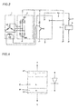
- Fig.3 is a circuit configuration diagram for showing an example of conventional rectifier device of a vehicle alternating-current generator.
- the conventional rectifier device with a vehicle alternating-current generator is configured with: an alternating-current generator 1 comprising a field coil 102 that is activated by a not shown vehicle engine (engine machine) to generate a rotating magnetic field, and armature windings 101 that generates and outputs an AC voltage by the generated rotating magnetic field; a rectifier 2 that rectifies a generated voltage of the alternating- current generator 1 to supply it from a main terminal to a battery 4 or an electric load 6; a voltage regulator 3 that controls an excitation current for the field coil 102 according to a terminal voltage of the battery 4 or the electric load 6 to thereby regulate the generated voltage of the alternating-current generator 1; a load switch 7 for connecting the generated voltage of the alternating current generator 1 to the electric load 6; and a key-switch 5 that allows the excitation current to flow from the battery 4 though the voltage regulator 3 to the field coil 102 when the engine machine is started.
- Fig.4 shows a structure of a PN junction diode in such a conventional device, which is a silicon diode given as each of semiconductor rectifier elements 201,202 that are used in the rectifier 2.
- the PN junction diode is configured by joining together a P-type semiconductor and an N-type semiconductor which are made of silicon, followed by forming an electrode E1 on the P-type semiconductor to establish an anode terminal A and forming an electrode E2 on the N-type semiconductor to establish a cathode terminal K.
- Patent Document 1 International Patent Application Publication No. WO 1999/036966
- This invention has been made to solve the problem as described above, and an object thereof is to provide a rectifier device of a vehicle alternating-current generator which can reduce power loss in comparison to that with the PN junction diode to thereby raise the output current upward, and which can suppress the reverse leakage current up to the same level as that with the PN junction diode to thereby eliminate risks of occurrence of thermal runaway due to heat generation of the diode under high temperature, false operation of the voltage regulator, and battery run-out during stopping of the engine (engine machine).
- the rectifier device of a vehicle alternating-current generator is a rectifier device that performs full-wave rectification of an output of the vehicle alternating-current generator, wherein, as a rectifier semiconductor element constituting the rectifier device, a diode is used which has a characteristic whose forward voltage drop with respect to a forward current is small and whose reverse leakage current is small.
- a schottky barrier diode having a junction barrier schottky structure is used so as to suppress the reverse leakage current.
- the rectifier device of a vehicle alternating-current generator since the schottky barrier diode is used in place of a PN junction diode, the forward voltage drop is made small to thereby reduce power loss and raise the output current upward, and also, heat generation due to the power loss is decreased, so that the temperature of the armature windings of the alternating-current generator becomes low thereby increasing the output current.
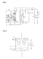
- Fig.1 is a circuit diagram for showing a rectifier device of a vehicle alternating-current generator, according to Embodiment 1 of the invention.
- What is the structural difference of Embodiment 1 from the conventional device illustrated in Fig.3 is that, in place of the PN-junction diodes 241, 202, diodes 201S, 202S which have a characteristic whose forward voltage drop with respect to a forward current is smaller than that of the PN junction diodes, and whose reverse leakage current is the same level as that of the PN junction diodes, are used as semiconductor elements of the rectifier 2.
- the other structures are similar to those in Fig.3 .
- the rectifier device with a vehicle alternating-current generator is configured with: an alternating-current generator 1 comprising a field coil 102 that is activated by a not shown vehicle engine (engine machine) to generate a rotating magnetic field, and armature windings 101 that generates and outputs an AC voltage by the generated rotating magnetic field; a rectifier 2 comprising rectifier semiconductor elements 201S, 202S that rectifies the generated voltage of the alternating-current generator 1 to supply it from a main terminal to a battery 4 or an electric load 6; a voltage regulator 3 that controls an excitation current for the field coil 102 according to a terminal voltage of the battery 4 or the electric load 6 to thereby regulate the generated voltage of the alternating-current generator 1; a load switch 7 for connecting the generated voltage of the alternating current generator 1 to the electric load 6; and a key-switch 5 that allows the excitation current to flow from the battery 4 though the voltage regulator 3 to the field coil 102 when the engine machine is started.
- an alternating-current generator 1 comprising a field
- Fig.2 is a cross-sectional view showing the structure of the schottky barrier diodes 201S, 202S as the rectifier semiconductor elements for constituting the rectifier 2 in Embodiment 1.
- the schottky barrier diode is configured with a barrier metal BM and a N-type semiconductor N which are joined together. Further, an anode terminal A is formed on the barrier metal BM through an electrode E1, and a cathode terminal K is formed on the N-type semiconductor through an electrode E2.
- a schottky barrier diode operates with many carriers and thus has a characteristic whose forward voltage drop is smaller that that of a PN-junction diode.
- a schottky barrier diode has a characteristic whose leakage current at the interface between the schottky electrode and the semiconductor becomes larger than that of a PN-junction diode when a voltage is applied in backward direction, because of the difference in work function between a metal for the electrode material and the semiconductor.
- a schottky barrier diode in order to suppress the reverse leakage current of a schottky barrier diode, such a schottky barrier diode is used as the diode for constituting the rectifier 2, which has a junction barrier schottky structure that is configured by forming a plurality of P-type semiconductor regions under the schottky barrier electrode BM constituting the schottky barrier diode so that PN junction portions are formed inside the schottky barrier diode.
- the depletion layer extends from the PN junction region when inversely biased, to thereby mitigate the electric field of the schottky junction region, so that the reverse leakage current can be decreased.
- the rectifier device for a vehicle alternating-current generator of Embodiment 1 of the invention uses a schottky barrier diode having a junction barrier schottky structure, as the rectifier semiconductor element constituting the rectifier device.
- the schottky barrier diode as in the rectifier device according to Embodiment 1 has a junction barrier schottky structure so that the reverse leakage current is suppressed up to the same level as that of the PN junction diode, it becomes possible to eliminate problems of occurrence of thermal runaway due to heat generation of the diode under high temperature, false operation of the voltage regulator, and battery run-out during stopping of the engine (engine machine).
- This invention is suitably applied to a rectifier device of an alternating-current generator to be mounted on a vehicle.
Landscapes
- Engineering & Computer Science (AREA)
- Power Engineering (AREA)
- Control Of Eletrric Generators (AREA)
- Rectifiers (AREA)
- Synchronous Machinery (AREA)
Abstract
Description
- This invention relates to rectifier devices of alternating-current generators for on-vehicle use, and in particular, to rectifier devices of vehicle alternating-current generators in which schottky barrier diodes are used as semiconductor devices constituting the rectifier devices.
-
Fig.3 is a circuit configuration diagram for showing an example of conventional rectifier device of a vehicle alternating-current generator. - The conventional rectifier device with a vehicle alternating-current generator is configured with: an alternating-
current generator 1 comprising afield coil 102 that is activated by a not shown vehicle engine (engine machine) to generate a rotating magnetic field, andarmature windings 101 that generates and outputs an AC voltage by the generated rotating magnetic field; a rectifier 2 that rectifies a generated voltage of the alternating-current generator 1 to supply it from a main terminal to a battery 4 or anelectric load 6; avoltage regulator 3 that controls an excitation current for thefield coil 102 according to a terminal voltage of the battery 4 or theelectric load 6 to thereby regulate the generated voltage of the alternating-current generator 1; aload switch 7 for connecting the generated voltage of thealternating current generator 1 to theelectric load 6; and a key-switch 5 that allows the excitation current to flow from the battery 4 though thevoltage regulator 3 to thefield coil 102 when the engine machine is started. -
Fig.4 shows a structure of a PN junction diode in such a conventional device, which is a silicon diode given as each of semiconductor rectifier elements 201,202 that are used in the rectifier 2. - As shown in
Fig.4 , the PN junction diode is configured by joining together a P-type semiconductor and an N-type semiconductor which are made of silicon, followed by forming an electrode E1 on the P-type semiconductor to establish an anode terminal A and forming an electrode E2 on the N-type semiconductor to establish a cathode terminal K. - In such a PN junction diode, there is a large forward voltage drop with respect to a forward current, thereby suppressing rise in output voltage to cause a limit for its output current.
- In addition, since a PN junction diode has a large forward voltage drop with respect to a forward current and therefore, generates large heat due to power loss, there is also a problem that the temperature of the
armature windings 101 of the alternating-current generator becomes higher, so that the output current is suppressed. - Thus, as another conventional rectifier device, there is proposed a device which is configured to reduce power loss of the vehicle alternating-current generator and to decrease a heat generation amount thereof, by using, as the semiconductor rectifier element, a schottky barrier diode made of silicon carbide in place of such a PN junction diode (see
Patent Document 1, for example). - Patent Document 1: International Patent Application Publication No.
WO 1999/036966 - However, in the conventional device disclosed in
Patent Document 1, although the voltage drop with respect to a forward current becomes smaller than that of the PN junction diode thereby making it possible to suppress heat generation due to the power loss, the reverse leakage current is larger than that of the PN junction diode. Thus, when a conventional schottky barrier diode is applied to the rectifier of a vehicle alternating-current generator, a problem arises in that there are risks of occurrence of thermal runaway due to heat generation of the diode under high temperature, false operation of the voltage regulator, and battery run-out during stopping of the engine (engine machine). - This invention has been made to solve the problem as described above, and an object thereof is to provide a rectifier device of a vehicle alternating-current generator which can reduce power loss in comparison to that with the PN junction diode to thereby raise the output current upward, and which can suppress the reverse leakage current up to the same level as that with the PN junction diode to thereby eliminate risks of occurrence of thermal runaway due to heat generation of the diode under high temperature, false operation of the voltage regulator, and battery run-out during stopping of the engine (engine machine).
- The rectifier device of a vehicle alternating-current generator according to the invention is a rectifier device that performs full-wave rectification of an output of the vehicle alternating-current generator, wherein, as a rectifier semiconductor element constituting the rectifier device, a diode is used which has a characteristic whose forward voltage drop with respect to a forward current is small and whose reverse leakage current is small.
- Further, in the rectifier device, as the diode, a schottky barrier diode having a junction barrier schottky structure is used so as to suppress the reverse leakage current.
- According to the rectifier device of a vehicle alternating-current generator, since the schottky barrier diode is used in place of a PN junction diode, the forward voltage drop is made small to thereby reduce power loss and raise the output current upward, and also, heat generation due to the power loss is decreased, so that the temperature of the armature windings of the alternating-current generator becomes low thereby increasing the output current.
- Further, since the reverse leakage current is suppressed up to the same level as that with the PN junction diode by applying a junction barrier schottky structure to the schottky barrier diode, there is provided an effect that eliminates risks of occurrence of thermal runaway due to heat generation of the diode under high temperature, false operation of the voltage regulator, and battery run-out during stopping of the engine (engine machine) .
- The foregoing and other objects, features and advantages of the present invention will become more apparent from the following detailed description of the embodiment and the accompanying drawings.
-
-
Fig.1 is a circuit diagram of a rectifier device of a vehicle alternating-current generator, according toEmbodiment 1 of the invention. -
Fig.2 is a cross-sectional view showing a structure of a schottky barrier diode used in the rectifier device according toEmbodiment 1 of the invention. -
Fig.3 is a circuit diagram for showing an example of conventional rectifier device of a vehicle alternating-current generator. -
Fig.4 is a cross-sectional view showing a structure of a PN junction diode used in the conventional rectifier device. -
Fig.1 is a circuit diagram for showing a rectifier device of a vehicle alternating-current generator, according toEmbodiment 1 of the invention. What is the structural difference ofEmbodiment 1 from the conventional device illustrated inFig.3 is that, in place of the PN-junction diodes 241, 202,diodes 201S, 202S which have a characteristic whose forward voltage drop with respect to a forward current is smaller than that of the PN junction diodes, and whose reverse leakage current is the same level as that of the PN junction diodes, are used as semiconductor elements of the rectifier 2. Thus, the other structures are similar to those inFig.3 . - That is, in
Fig.1 , the rectifier device with a vehicle alternating-current generator is configured with: an alternating-current generator 1 comprising afield coil 102 that is activated by a not shown vehicle engine (engine machine) to generate a rotating magnetic field, andarmature windings 101 that generates and outputs an AC voltage by the generated rotating magnetic field; a rectifier 2 comprisingrectifier semiconductor elements 201S, 202S that rectifies the generated voltage of the alternating-current generator 1 to supply it from a main terminal to a battery 4 or anelectric load 6; avoltage regulator 3 that controls an excitation current for thefield coil 102 according to a terminal voltage of the battery 4 or theelectric load 6 to thereby regulate the generated voltage of the alternating-current generator 1; aload switch 7 for connecting the generated voltage of thealternating current generator 1 to theelectric load 6; and a key-switch 5 that allows the excitation current to flow from the battery 4 though thevoltage regulator 3 to thefield coil 102 when the engine machine is started. -
Fig.2 is a cross-sectional view showing the structure of theschottky barrier diodes 201S, 202S as the rectifier semiconductor elements for constituting the rectifier 2 inEmbodiment 1. - In
Fig.2 , the schottky barrier diode is configured with a barrier metal BM and a N-type semiconductor N which are joined together. Further, an anode terminal A is formed on the barrier metal BM through an electrode E1, and a cathode terminal K is formed on the N-type semiconductor through an electrode E2. - In general, a schottky barrier diode operates with many carriers and thus has a characteristic whose forward voltage drop is smaller that that of a PN-junction diode. However, on the other side, a schottky barrier diode has a characteristic whose leakage current at the interface between the schottky electrode and the semiconductor becomes larger than that of a PN-junction diode when a voltage is applied in backward direction, because of the difference in work function between a metal for the electrode material and the semiconductor.
- Thus, in
Embodiment 1 of the invention, in order to suppress the reverse leakage current of a schottky barrier diode, such a schottky barrier diode is used as the diode for constituting the rectifier 2, which has a junction barrier schottky structure that is configured by forming a plurality of P-type semiconductor regions under the schottky barrier electrode BM constituting the schottky barrier diode so that PN junction portions are formed inside the schottky barrier diode. - In the schottky barrier diode having the thus-configured junction barrier schottky structure, the depletion layer extends from the PN junction region when inversely biased, to thereby mitigate the electric field of the schottky junction region, so that the reverse leakage current can be decreased.
- As described above, the rectifier device for a vehicle alternating-current generator of
Embodiment 1 of the invention, uses a schottky barrier diode having a junction barrier schottky structure, as the rectifier semiconductor element constituting the rectifier device. - Consequently, according to the rectifier device for a vehicle alternating-current generator of
Embodiment 1 of the invention, since the forward voltage drop of the schottky barrier diode with respect to the forward current is smaller than that of a PN junction diode, it becomes possible to make the output voltage higher, thereby raising the output current upward. - In addition, since the forward voltage drop is smaller than that of a PN junction diode and accordingly the heat generation becomes smaller, there is provided an effect that the temperature of the armature windings of the alternating-current generator becomes lower to thereby increase the output current.
- Further, since the schottky barrier diode as in the rectifier device according to
Embodiment 1 has a junction barrier schottky structure so that the reverse leakage current is suppressed up to the same level as that of the PN junction diode, it becomes possible to eliminate problems of occurrence of thermal runaway due to heat generation of the diode under high temperature, false operation of the voltage regulator, and battery run-out during stopping of the engine (engine machine). - This invention is suitably applied to a rectifier device of an alternating-current generator to be mounted on a vehicle.
- 1: alternating-current generator, 2: rectifier, 3: voltage regulator, 4: battery, 5: key switch, 6: electric load, 7: load switch, 201,202: rectifier semiconductor elements (schottky barrier diodes), BM: barrier metal (schottky electrode), N: N-type semiconductor, E1, E2: electrodes, A: anode terminal, K: cathode terminal.
Claims (3)
- A rectifier device of a vehicle alternating-current generator that performs full-wave rectification of an output of the vehicle alternating-current generator, wherein, as a rectifier semiconductor element constituting the rectifier device, a diode is used which has a characteristic whose forward voltage drop with respect to a forward current is smaller than that of a PN junction diode, and whose reverse leakage current is as small as the same level as that of the PN junction diode.
- The rectifier device of a vehicle alternating-current generator of Claim 1, wherein, as the diode, a schottky barrier diode having a junction barrier schottky structure is used so as to suppress the reverse leakage current.
- The rectifier device of a vehicle alternating-current generator of Claim 2, wherein the junction barrier schottky structure includes a plurality of P-type semiconductor regions formed under a schottky electrode, so that PN junction portions are formed inside the schottky barrier diode.
Applications Claiming Priority (1)
| Application Number | Priority Date | Filing Date | Title |
|---|---|---|---|
| PCT/JP2011/071821 WO2013046289A1 (en) | 2011-09-26 | 2011-09-26 | Rectifier of alternating-current generator for vehicle |
Publications (2)
| Publication Number | Publication Date |
|---|---|
| EP2763302A1 true EP2763302A1 (en) | 2014-08-06 |
| EP2763302A4 EP2763302A4 (en) | 2015-04-29 |
Family
ID=47994408
Family Applications (1)
| Application Number | Title | Priority Date | Filing Date |
|---|---|---|---|
| EP11873203.1A Withdrawn EP2763302A4 (en) | 2011-09-26 | 2011-09-26 | ALTERNATOR RECTIFIER FOR A VEHICLE |
Country Status (5)
| Country | Link |
|---|---|
| US (1) | US20140048901A1 (en) |
| EP (1) | EP2763302A4 (en) |
| JP (1) | JP5734446B2 (en) |
| CN (1) | CN103636112A (en) |
| WO (1) | WO2013046289A1 (en) |
Families Citing this family (3)
| Publication number | Priority date | Publication date | Assignee | Title |
|---|---|---|---|---|
| JP6053103B2 (en) * | 2012-04-12 | 2016-12-27 | 富士電機株式会社 | Wide band gap semiconductor device and method of manufacturing the same |
| CN105515094A (en) * | 2015-12-04 | 2016-04-20 | 合肥工业大学 | A battery management system charging wake-up circuit |
| JP7464966B2 (en) * | 2020-01-31 | 2024-04-10 | 株式会社Eサーモジェンテック | Thermoelectric Power Generation System |
Family Cites Families (10)
| Publication number | Priority date | Publication date | Assignee | Title |
|---|---|---|---|---|
| US4641174A (en) * | 1983-08-08 | 1987-02-03 | General Electric Company | Pinch rectifier |
| JPH02137368A (en) * | 1988-11-18 | 1990-05-25 | Toshiba Corp | Semiconductor rectifier |
| JP3812693B2 (en) * | 1997-07-18 | 2006-08-23 | 三菱電機株式会社 | Vehicle driving state detection device |
| WO1999036966A1 (en) | 1998-01-14 | 1999-07-22 | Mitsubishi Denki Kabushiki Kaisha | Rectifying equipment |
| JP2001085705A (en) * | 1999-09-16 | 2001-03-30 | Fuji Electric Co Ltd | Schottky barrier diode manufacturing method |
| US7186609B2 (en) * | 1999-12-30 | 2007-03-06 | Siliconix Incorporated | Method of fabricating trench junction barrier rectifier |
| US7084610B2 (en) * | 2004-01-06 | 2006-08-01 | Visteon Global Technologies, Inc. | Alternator rectifier |
| US7671439B2 (en) * | 2005-02-11 | 2010-03-02 | Alpha & Omega Semiconductor, Ltd. | Junction barrier Schottky (JBS) with floating islands |
| US20070158804A1 (en) * | 2006-01-10 | 2007-07-12 | Semiconductor Energy Laboratory Co., Ltd. | Semiconductor device, manufacturing method of semiconductor device, and RFID tag |
| JP2007274818A (en) * | 2006-03-31 | 2007-10-18 | Toshiba Corp | Rectifier |
-
2011
- 2011-09-26 US US14/112,981 patent/US20140048901A1/en not_active Abandoned
- 2011-09-26 EP EP11873203.1A patent/EP2763302A4/en not_active Withdrawn
- 2011-09-26 WO PCT/JP2011/071821 patent/WO2013046289A1/en not_active Ceased
- 2011-09-26 CN CN201180072051.XA patent/CN103636112A/en active Pending
- 2011-09-26 JP JP2013535650A patent/JP5734446B2/en not_active Expired - Fee Related
Also Published As
| Publication number | Publication date |
|---|---|
| US20140048901A1 (en) | 2014-02-20 |
| WO2013046289A1 (en) | 2013-04-04 |
| JP5734446B2 (en) | 2015-06-17 |
| CN103636112A (en) | 2014-03-12 |
| EP2763302A4 (en) | 2015-04-29 |
| JPWO2013046289A1 (en) | 2015-03-26 |
Similar Documents
| Publication | Publication Date | Title |
|---|---|---|
| TWI580169B (en) | Rectifier, rectifier configuration and generator for motorized vehicle | |
| US20160204648A1 (en) | In-vehicle charger | |
| TWI618256B (en) | Pseudo-Schottky diode | |
| JP5939260B2 (en) | Generator device for supplying voltage to automobiles | |
| JP3555250B2 (en) | Automotive alternators and Schottky barrier diodes | |
| US20150021747A1 (en) | Diode | |
| US9018633B2 (en) | Semiconductor device | |
| US11139683B2 (en) | Systems and methods for high efficiency power conversion | |
| CN101803029B (en) | Semiconductor device and method for the production thereof | |
| US20180261700A1 (en) | High withstand voltage diode and power conversion device | |
| EP2763302A1 (en) | Rectifier of alternating-current generator for vehicle | |
| US20140001927A2 (en) | Rectifierarrangement having schottky diodes | |
| KR20070089677A (en) | Semiconductor device and rectifier device | |
| CN102208456A (en) | Stacked P+-P Junction Barrier Controlled Schottky Diodes | |
| TWI528567B (en) | A power semiconductor device, a rectifying device and a power supply device | |
| US10083870B2 (en) | Semiconductor device | |
| JP2011234614A (en) | Rectifier bridge circuit | |
| CN209497365U (en) | A kind of low-loss automobile current generator of drop | |
| WO1999036966A1 (en) | Rectifying equipment | |
| Zhang | Roles of semiconductor junctions in mechanical-electrical power conversion | |
| CN206497895U (en) | bridge rectifier diode | |
| JP4902996B2 (en) | Resin-encapsulated diode and voltage doubler rectifier circuit | |
| CN109713852A (en) | A kind of low-loss automobile current generator of drop | |
| CN208489203U (en) | A kind of bridge rectifier diode | |
| US20120262963A1 (en) | Multi-phase rectifier of alternator |
Legal Events
| Date | Code | Title | Description |
|---|---|---|---|
| PUAI | Public reference made under article 153(3) epc to a published international application that has entered the european phase |
Free format text: ORIGINAL CODE: 0009012 |
|
| 17P | Request for examination filed |
Effective date: 20131106 |
|
| AK | Designated contracting states |
Kind code of ref document: A1 Designated state(s): AL AT BE BG CH CY CZ DE DK EE ES FI FR GB GR HR HU IE IS IT LI LT LU LV MC MK MT NL NO PL PT RO RS SE SI SK SM TR |
|
| DAX | Request for extension of the european patent (deleted) | ||
| RA4 | Supplementary search report drawn up and despatched (corrected) |
Effective date: 20150326 |
|
| RIC1 | Information provided on ipc code assigned before grant |
Ipc: H01L 29/872 20060101ALI20150320BHEP Ipc: H01L 29/06 20060101ALI20150320BHEP Ipc: H02M 7/06 20060101AFI20150320BHEP |
|
| 17Q | First examination report despatched |
Effective date: 20171221 |
|
| STAA | Information on the status of an ep patent application or granted ep patent |
Free format text: STATUS: THE APPLICATION HAS BEEN WITHDRAWN |
|
| 18W | Application withdrawn |
Effective date: 20180416 |