EP2763297A2 - Power generation device, transmission device and switching device - Google Patents
Power generation device, transmission device and switching device Download PDFInfo
- Publication number
- EP2763297A2 EP2763297A2 EP14150142.9A EP14150142A EP2763297A2 EP 2763297 A2 EP2763297 A2 EP 2763297A2 EP 14150142 A EP14150142 A EP 14150142A EP 2763297 A2 EP2763297 A2 EP 2763297A2
- Authority
- EP
- European Patent Office
- Prior art keywords
- power generation
- generation device
- operation force
- state
- armature
- Prior art date
- Legal status (The legal status is an assumption and is not a legal conclusion. Google has not performed a legal analysis and makes no representation as to the accuracy of the status listed.)
- Granted
Links
Images






Classifications
-
- H—ELECTRICITY
- H02—GENERATION; CONVERSION OR DISTRIBUTION OF ELECTRIC POWER
- H02K—DYNAMO-ELECTRIC MACHINES
- H02K35/00—Generators with reciprocating, oscillating or vibrating coil system, magnet, armature or other part of the magnetic circuit
- H02K35/06—Generators with reciprocating, oscillating or vibrating coil system, magnet, armature or other part of the magnetic circuit with moving flux distributors, and both coil systems and magnets stationary
-
- H—ELECTRICITY
- H02—GENERATION; CONVERSION OR DISTRIBUTION OF ELECTRIC POWER
- H02K—DYNAMO-ELECTRIC MACHINES
- H02K21/00—Synchronous motors having permanent magnets; Synchronous generators having permanent magnets
- H02K21/12—Synchronous motors having permanent magnets; Synchronous generators having permanent magnets with stationary armatures and rotating magnets
- H02K21/14—Synchronous motors having permanent magnets; Synchronous generators having permanent magnets with stationary armatures and rotating magnets with magnets rotating within the armatures
Definitions
- the present invention relates to a power generation device and the like for inducing current to a coil according to a principle of electromagnetic induction.
- a wide variety of applications is anticipated of a power generation device capable of generating power with a simple operation involved in daily performance. This is because the power generation device can operate small electric machinery and apparatus that requires instantaneous power for simple operation without a power source such as a battery. Therefore, the power generation device has been widely researched.
- US 2011/0285487 A discloses an electromagnetic energy converter, including two electromagnetic members and an electric coil, for converting machine energy to electric energy.
- JP 2009-516802 W discloses a self-power generation device including a magnetic circuit that passes through a central opening of an excitation coil for a plurality of times to form at least one loop.
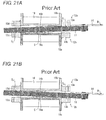
- FIG. 21A A structure of a conventional power generation device shown in US 2011/0285487 A and JP 2009-516802 W will be described based on Figs. 21A and 21 B.
- Figs. 21A and 21 B show an internal structure of the conventional power generation device, where Fig. 21A is a cross-sectional view when the power generation device is in an initial state, and Fig. 21 B is a cross-sectional view when the power generation device is in a final state.
- a protrusion 18a and a protrusion 18b are respectively arranged in an extending manner on a spool 19a and a spool 19b with a central part C of an armature 11 interposed therebetween.
- the armature 11 is attracted at attracting positions S 1 and S 2 by the magnetic force of an end 13a of a yoke 12a and an end 13c of a yoke 12b.
- the armature 11 is thus supported in an orientation of diagonally passing through a space defined by the spool 19a and the spool 19b.
- the conventional power generation device still has a problem in that the operation force that needs to be applied on the operation position W is significantly large as compared to the force exerted by the daily performance. In other words, the conventional power generation device lacks in usability since the user feels a sense of discomfort if a force larger than usual is necessary or the user needs to be conscious of strongly pushing in the spring 14.
- a structural defect of the conventional power generation device causes the above problem.
- the armature 11 always rotates with the central part C as the supporting point, and thus the conventional power generation device requires an operation force greater than the sum of the magnetic forces by the two ends (the end 13a and the end 13c in Fig. 21A , the end 13b and the end 13d in Fig. 21 B) .
- the sum of the magnetic forces is not large enough to cause problems in operating the armature 11 but is large enough to an extent of causing the problems described above.
- the simplest method for solving the above problems is to advantageously apply the principle of leverage by extending the distance from the central part C to the operation position W.
- a method is not a preferred method since it enlarges the power generation device and newly causes problems of stretching the operation stroke, and the like.
- the present invention has been made in view of solving the problems described above, and an object thereof is to provide a power generation device and the like having higher power generation efficiency than the related art with a simple mechanism without enlarging the device or extending an operation stroke.
- a power generation device including a rotation member configured to rotate by an externally applied operation force, and a supporting member configured to support the rotation member by attracting the rotation member with a magnetic force exerted at a predetermined portion of the supporting member, where the power generation device is configured to induce a current to a coil by causing a magnetic flux of a permanent magnet passing through the coil to fluctuate in cooperation with the rotation of the rotation member, and where when the operation force is applied in a first state in which the rotation member is supported by the supporting member by being attracted to a first portion and to a second portion of the supporting member at a respective first position and a second position of the supporting member, the rotation member transitions to a second state by rotating with the first position of the supporting member as a first supporting point, and further transitions to a third state by rotating with a position of the supporting member different from the first position as a second supporting point.
- the rotation member rotates with the central part thereof (portion between two protrusions) as the exclusive supporting point, and thus the operation force has to simultaneously act on the respective positions where the rotation member is attracted to the two ends.
- the conventional power generation device requires an operation force greater than the sum of the magnetic forces by the two ends, which may give a sense of discomfort to the user or may cause the user to be conscious of operating strongly.
- the rotation member transitions to the second state by rotating with the first position as the first supporting point when the operation force is applied in the first state.
- the operation force acts only on the second position and thus the operation force merely needs to be a magnitude greater than the magnetic force by the second portion in the supporting member.
- the rotation member transitions to the third state by rotating with the position different from the first position as the second supporting point.
- the operation force acts only on the first position and thus the operation force merely needs to be a magnitude greater than the magnetic force by the first portion. That is, the power generation device according to one aspect of the present invention does not require the operation force greater than the sum of the magnetic forces all at once as in the conventional power generation device, and requires only the operation force greater than the respective magnetic forces in order (with time difference).
- the power generation device can generate power with an operation force smaller than the operation force required in the conventional power generation device with a simple mechanism without enlarging the device or extending the operation stroke.
- the power generation device can generate power of the same amount as the power that can be generated by the conventional power generation device, and thus can generate power at higher power generation efficiency than the conventional power generation device.
- the rotation member when supported by the supporting member with a space provided between the rotation member and a position to become the second supporting point in the first state, the rotation member may rotate with the first position as the first supporting point, and then rotate with the position different from the first position as the second supporting point, and (2) by the rotation, the rotation member may transition to the second state by acting the operation force on the second position in the first state, and then transition to the third state by acting the operation force on the first position.
- the conventional power generation device requires the operation force greater than the sum of the magnetic forces by the two ends. Since the rotation member rotates with the central part thereof (portion between two protrusions) as the exclusive supporting point, the operation force has to simultaneously act on the respective positions where the rotation member is attracted to the two ends.
- the rotation member and the position to become the second supporting point are not in contact with each other, and the rotation member is supported by the supporting member with a space provided between the rotation member and the position to become the second supporting point.
- the rotation member rotates with the first position as the first supporting point so that the operation force acts on the second position (transition from the first state to the second state), the rotation member rotates with the position different from the first position as the second supporting point (transition from the second state to the third state).
- the power generation device interchanges the supporting point of the rotation according to the position (the first position, the second position) to act the operation force without fixing the supporting point about which the rotation member rotates as in the conventional power generation device.
- the power generation device according to one aspect of the present invention does not require the operation force greater than the sum of the magnetic forces all at once as in the conventional power generation device, and requires only the operation force greater than the respective magnetic forces in order (with time difference).
- the power generation device can generate power with an operation force smaller than the operation force required in the conventional power generation device with a simple mechanism without enlarging the device or extending the operation stroke.
- the power generation device thus can generate power of the same amount as the power that can be generated by the conventional power generation device, and hence can generate power at higher power generation efficiency than the conventional power generation device.
- the rotation member when the rotation member further rotates in the third state, the rotation member may further transition to a fourth state in which the rotation member is supported by the supporting member by being attracted to a third portion and a fourth portion in the supporting member at a third position and a fourth position with a space provided between the rotation member and the position to become the second supporting point.
- the rotation member when the rotation member further rotates from the third state, the rotation member is supported by the supporting member in an orientation of being attracted to the third portion and the fourth portion in the supporting member (fourth state).
- the rotation member and the position to become the second supporting point e.g., central part of the rotation member
- the rotation member and the position to become the second supporting point are not in contact with each other, and the rotation member is supported with a space provided between the rotation member and the position to become the second supporting point.
- the power generation device when the power generation device according to one aspect of the present invention transitions from the fourth state to the first state through the third state and the second state, the power generation device can interchange the supporting point of the rotation according to the position to act the operation force without fixing the supporting point about which the rotation member rotates as in the conventional power generation device.
- the power generation device does not require the operation force greater than the sum of the magnetic forces all at once as in the conventional power generation device, and requires only the operation force greater than the respective magnetic forces in order (with time difference). Therefore, the power generation device according to one aspect of the present invention can generate power at higher power generation efficiency than in the related art with a simple mechanism without enlarging the device or extending the operation stroke.
- a distance from the first position to a position to apply the operation force may be longer than a distance from the position to become the second supporting point to the position to apply the operation force.
- the power generation device does not require the operation force greater than the sum of the magnetic forces all at once as in the conventional power generation device, and requires only the operation force greater than the respective magnetic forces in order (with time difference).
- the distance from the first supporting point to the position (force point) to apply the operation force is longer than the distance from the position to become the second supporting point to the operation position, and thus the operation force acts on the second position with the principle of leverage acting more advantageously than in the convention power generation device having the central part of the rotation member as the exclusive supporting point.
- the power generation device can generate power with an operation force smaller than the operation force required in the conventional power generation device, and hence can generate power at higher power generation efficiency than in the conventional power generation device.
- the rotation member may rotate with a protrusion as the second supporting point, the protrusion being arranged at a predetermined position of a fixing member configured to fix the supporting member.
- the power generation device interchanges the supporting point of the rotation according to the position to act the operation force without fixing the supporting point about which the rotation member rotates as in the conventional power generation device. Therefore, the power generation device according to one aspect of the present invention can generate power at higher power generation efficiency than in the related art with a simple mechanism without enlarging the device or extending the operation stroke.
- the protrusion may be a rectangle.
- the power generation device described above can be easily manufactured since only simple processing is necessary (additional processing is not necessary).
- the protrusion may have a shape in which the rectangular edge is cut off. The area at which the rotation member and the protrusion make contact thus becomes constant, and a situation can be avoided in which the load is intensively applied to only a specific portion of the rotation member. Therefore, the shape of the protrusion with smoothened edge can enhance the durability of the rotation member and extend the durable years of the power generation device.
- the protrusion arranged at the predetermined position of the fixing member may be supported by an elastic member that exerts stress.
- the power generation device when the power generation device transitions the state of the operation, the stress of the elastic member accelerates the rotation of the rotation member. Therefore, the power generation device can generate power with an operation force smaller than the operation force required in the conventional power generation device, and hence can generate power at higher power generation efficiency than the conventional power generation device.
- the fixing member to which the protrusion is arranged may have a configuration that can deflect up and down.
- the stress of the elastic member is further strengthened, and the structure can further improve the power generation efficiency of the power generation device.
- a transmission device is configured to transmit signals to an external device using power generated by the power generation device described above.
- the transmission device is electrically connected with the power generation device, and the power required when transmitting the signal to the external device is provided by the power generated by the power generation device. Therefore, the transmission device according to another aspect of the present invention can transmit signals without mounting a power source such as a battery.
- a switching device relates to (1) a switching device configured to switch states of an external device, (2) the switching device including the power generation device described above; and (3) the transmission device described above.
- the switching device can cause the transmission device to transmit signals to the external device using the power generated by the power generation device and cause the external device to receive the signals to switch the state of the external device without mounting the power source such as the battery.
- the wiring for connecting the switching device according to still another aspect of the present invention and the external device is not necessary, and the switching device can resolve all the demerits associated with the arrangement of the wiring.
- the switching device can be applied as a device (electrical switch or the like) for switching ON/OFF of the external device such as the indoor illumination device.
- the wiring for connecting the switching device and the indoor illumination device does not need to be embedded in the wall surface, and thus the switching device not only reduces the cost, but also enables a free indoor layout that is not inhibited by the wiring.
- the rotation member when the operation force is applied in the first state in which the rotation member is supported by the supporting member by being attracted to the first portion and the second portion in the supporting member at the first position and the second position, the rotation member rotates with the first position as the first supporting point to transition to the second state, and rotates with the position different from the first position as the second supporting point to further transition to the third state.
- the power generation device has an effect of being able to generate power at higher power generation efficiency than in the related art with a simple mechanism without enlarging the device or extending the operation stroke.
- Fig. 1 is a cross-sectional view showing an internal structure of the power generation device when the power generation device 10 is in a first state. The relationship of the entire power generation device 10 and the cross-section shown in Fig. 1 will be described below with reference to Fig. 5D .
- the power generation device 10 is a device that fluctuates the magnetic flux of a permanent magnet 7 (not shown in the cross-section of Fig. 1 , see Fig. 5B ) passing through a coil 6 so as to cooperatively operate with rotation of an armature 1 to induce current to the coil.
- the power generation device 10 includes the armature 1, a yoke 2a, a yoke 2b, a spring 4, the coil 6, the permanent magnet 7, a spool 9a, and a spool 9b.
- the armature (rotation member) 1 is a member having a double hook shape (i.e., a shape in which two small plate-like members of the same shape are added to the side surface of a plate-like member so that both ends of the plate-like member have a substantially right angle hook shape), where long side portions of the double hook shape are mounted on the spool 9a.
- the spool 9b is placed so as to cover the long side portions, and the spool 9a and the spool 9b are fitted from top and bottom to form a cuboid portion E configured by covering the long side portions, where the cuboid portion is hereinafter referred to as "bobbin".
- the widths of the spool 9a and the spool 9b are substantially the same as the lengths of the long side portions, and the hook shaped portions of the armature 1 are extended from the bobbin so that a portion curved to a substantially right angle is exposed.
- the coil 6 is a member for retrieving current (electric energy) from a fluctuating magnetic field.
- the coil 6 is mounted on the spool 9b so as to cover the bobbin.
- a predetermined device e.g., wireless device or the like, described in detail below
- that uses the induced current is connected to both ends of the coil 6 by way of an electric circuit.
- the spring 4 is fixed to one hook shaped portion of the armature 1 by a fixing pin 5. Therefore, the armature 1 operates inside the bobbin when an arbitrary operation position W in the spring 4 is pushed.
- the process in which the armature 1 operates will be described in detail below with reference to Figs. 1 to 4 which illustrates a series of cross-sectional views showing the process of the relevant operation.
- the yoke (supporting member) 2a and the yoke (supporting member) 2b are plate-like members. As will be described below, the yokes are formed by using a soft magnetic material, and thus the yoke 2a and the yoke 2b themselves have properties of a magnet.
- both ends of the yoke 2a are referred to as an end (second portion) 3a and an end (fourth portion) 3d
- both ends of the yoke 2b are referred to as an end (third portion) 3b and an end (first portion) 3c.
- the yoke 2b and the spool (fixing member) 9a are fitted from top and bottom with the yoke 2b on the bottom and the spool (fixing member) 9a on the top.
- a short circular column shaped protrusion is formed substantially at the middle of the yoke 2b, and the permanent magnet is mounted on the yoke 2b with the protrusion fitted into a central part (referring to a hollow hole, the diameter of the hole being substantially the same as the diameter of the protrusion) of the doughnut-shaped (i.e., a shape in which the central part of the circular column is made hollow) permanent magnet 7.
- a similar protrusion is also arranged substantially at the middle of the yoke 2a.
- the yoke 2a is mounted on the spool 9a with the protrusion fitted into the central part of the permanent magnet 7 from above so as to sandwich the permanent magnet 7 with the yoke 2a and the yoke 2b.
- the permanent magnet 7 is sandwiched by the two yokes from the top and the bottom with the central part fixed by the protrusions respectively arranged in the yoke 2a and the yoke 2b, and the three sides surrounded by the bobbin and the two hook-shaped portions of the armature 1.
- the permanent magnet 7 is therefore not shown in the cross-sectional view of Fig. 1 .
- Both ends of the yoke 2a and the yoke 2b are extended from the spool 9a, and are positioned to sandwich the ends of the hook shaped portions of the armature 1 from the top and bottom.
- a spacing (substantially equal to the thickness of the permanent magnet 7) between the yoke 2a and the yoke 2b is greater than the thickness of the armature 1, and thus the ends of the hook shaped portions of the armature 1 are not sandwiched by the ends of the yokes.
- a protrusion 8a and a protrusion 8b are arranged in an extending manner on the spool 9a and the spool 9b in the width direction of the long side portions of the double hook shape of the armature 1.
- the armature 1 is inhibited from being attracted to both ends of one yoke, whereby the armature 1 is constantly supported in an orientation of diagonally passing through the interior of the bobbin by the magnetic force of the ends positioned diagonally with respect to each other with the armature 1 therebetween.
- a state in which the armature 1 is supported inside the bobbin in the above orientation is hereinafter referred to as a "first state".
- the protrusion 8b merely prevents the armature 1 from being attracted to the end 3a and the end 3d of the yoke 2a, and is not directly related to the operation of the armature 1 to be described below. Therefore, the protrusion 8b may not be arranged in an extending manner on the spool 9b.
- the surfaces of the respective ends where the ends 3a to 3d make contact with the armature 1 have an angle substantially equal to an angle formed by the orientation of the armature 1 with respect to the surface of the interior of the bobbin.
- the respective ends and the armature 1 make contact at the surface and the armature 1 does not make contact with the respective ends at the corner of the respective ends.
- the center of a surface where the armature 1 is attracted to the end 3a is an attracting position (second position) S 1
- the center of a surface where the armature 1 is attracted to the end 3c is an attracting position (first position) S 2
- the center of a surface where the armature 1 is attracted to the end 3b is an attracting position (third position) S 3
- the center of a surface where the armature 1 is attracted to the end 3d is an attracting position (fourth position) S 4 (see Fig. 4 ).
- the armature 1 and the protrusion 8a do not come into contact with each other, and thus a space (hereinafter referred to as "clearance A") is formed between the armature 1 and the protrusion 8a from the distal end of the protrusion 8a to the surface of the armature 1 in a perpendicularly upward direction. Therefore, when the spring 4 is pushed down at an arbitrary operation position W, the armature 1 starts to rotate in a direction such that the armature 1 approaches the end 3b from the end 3a, with the attracting position S 2 as the supporting point, not the protrusion 8a. In other words, as opposed to the conventional structure (see Figs. 21A and 21 B ) in which the clearance A does not exist and the armature constantly rotates with the central part of the armature as the supporting point, the central part C of the armature 1 rotates with the operation position W.
- an operation force greater than the sum of the magnetic forces by the two ends is not necessary as in the conventional power generation device, and an operation force greater than the respective magnetic forces merely needs to be exerted (with time difference) in the power generation device 10.
- a distance (L 1 + L 2 ) from the attracting position S 2 (supporting point) to the operation position W (force point) is longer than a distance (L 1 /2 + L 2 ) from the central part C to the operation position W.
- the operation force acts on the attracting position S 1 (acting point) in a state where the principle of leverage is acting more advantageously than in the conventional power generation device.
- the power generation device 10 can generate power with a smaller operation force than the operation force required in the conventional power generation device with a simple mechanism without enlarging the device or extending the operation stroke. Since the power generation device 10 can generate power of the same amount as the power that can be generated by the conventional power generation device, the power generation device 10 capable of generating power with smaller operation force than the related art can generate power at higher power generation efficiency than the conventional power generation device.
- the armature 1 is made using a soft magnetic material such as permalloy, pure iron (e.g., SUY-0), and the like.
- the armature 1 has a dimension of 8 mm vertically, 20 mm horizontally, and 1.4 mm in thickness.
- such dimension is merely illustrative for the sake of explanation, and can be arbitrarily changed depending on the dimension of the power generation device 10.
- the yoke 2a and the yoke 2b are made using a soft magnetic material such as permalloy, pure iron (e.g., SUY-0), and the like.
- a soft magnetic material such as permalloy, pure iron (e.g., SUY-0), and the like.
- the distance in the perpendicular direction distance in the vertical direction in the cross-sectional view shown in Fig.
- the movable angle of the armature 1 i.e., the angle formed by the orientation of the armature 1 diagonally passing through the interior of the bobbin with respect to the surface of the interior of the bobbin
- the spacing between the yoke 2a and the yoke 2b is obtained in accordance with the distance in the perpendicular direction.
- the movable angle and the spacing are both arbitrarily changeable.
- the yoke 2a, the yoke 2b, and the spring 4 respectively have appropriate dimensions such that the distance L 1 from the attracting position S 1 to the attracting position S 2 becomes 15 mm, and the distance L 2 from the attracting position S 1 to the operation position W becomes 10 mm.
- the spring 4 is made using a non-magnetic material such as stainless steel (SUS).
- SUS stainless steel
- the spool 9 is made using resin such as polycarbonate (PC), polybutylene terephthalate (PBT), ABS (collective term of Acrylonitrile, Butadiene, Styrene copolymer synthetic resin) or a non-magnetic metal such as copper.
- PC polycarbonate
- PBT polybutylene terephthalate
- ABS collective term of Acrylonitrile, Butadiene, Styrene copolymer synthetic resin
- a non-magnetic metal such as copper.
- the height of the protrusion 8a may be 0.2 mm, for example.
- the process in which the power generation device 10 operates will be described based on Figs. 1 to 4 .
- the armature 1 starts to rotate with the attracting position (first position) S 2 as the supporting point (first supporting point) when the spring 4 is pushed down at the arbitrary operation position W. This is because in the first state, the armature 1 and the protrusion 8a are not in contact with each other such that the clearance A exists, and the central part C accordingly rotates with the operation position W.
- Fig. 2 is a cross-sectional view showing an internal structure of the power generation device when the power generation device 10 is in a second state.
- the operation force applied on the operation position W becomes greater than the magnetic force fixing the armature 1, and the armature 1 rotates away from the end 3a, the armature makes contact with the protrusion 8a at the central part C.
- the armature 1 starts to rotate with the protrusion 8a as the supporting point (i.e., the second supporting point).
- the state shown in Fig. 2 is hereinafter referred to as "second state".
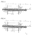
- Fig. 3 is a cross-sectional view showing an internal structure of the power generation device when the power generation device 10 is in a third state.
- the armature 1 when the armature 1 is further rotated from the second state, the armature is attracted to the end 3b at the attracting position S 3 .
- the force for rotating the armature 1 becomes greater than the magnetic force by the end 3c, the armature separates away from the end 3c and further rotates.
- the state shown in Fig. 3 is hereinafter referred to as the "third state".
- Fig. 4 is a cross-sectional view showing an internal structure of the power generation device when the power generation device 10 is in a fourth state.
- the armature 1 when the armature 1 further rotates from the third state, the armature 1 separates away from the protrusion 8a (clearance A is formed) and rotates with the attracting position S 3 as the supporting point by the inertia caused by the rotation, the magnetic force by the end 3d, and the operation force applied on the operation position W.
- the central part C rotates with a left end portion D of the armature 1.
- the armature 1 is attracted to the end 3d at the attracting position S 4 .
- the armature 1 is supported in an orientation of passing through the bobbin diagonally opposite to the first state.
- the state shown in Fig. 4 is hereinafter referred to as the "fourth state”.
- the supporting point of the rotation is interchanged between the attracting position S 2 or S 3 and the protrusion 8a in the process of the operation, and the power generation device 10 transitions from the first state to the fourth state.
- the magnetic flux of the permanent magnet 7 fluctuates, and the power generation device can induce current to the coil 6.
- the power generation device 10 transitions from the first state to the fourth state through the second state and third state.
- the power generation device 10 can transition from the fourth state to the first state through the second state and the third state.
- the supporting point of the rotation is interchanged between the attracting position S 2 or S 3 and the protrusion 8a in the process of the operation, similar to above.
- the process of the operation changes according to the position of acting the operation force.
- the power generation device 10 has the effect of being able to generate power at higher power generation efficiency than the conventional power generation device, similar to when the transition is made from the first state to the fourth state.
- Figs. 5A to 5D are exploded perspective views each showing, in a step-wise manner, an assembly process of the power generation device 10, where Fig. 5A shows a first assembly process, Fig. 5B shows a second assembly process, Fig. 5C shows a third assembly process, and Fig. 5D shows an outer appearance of the power generation device 10 in which the assembly is completed.
- Figs. 1 to 4 described above correspond to the cross-sectional views taken along line B-B in Fig. 5D .
- the power generation device 10 is assembled as shown in Figs. 5A to 5D .
- the spring 4 is fixed to the armature 1 by the fixing pin 5
- the long side portion of the armature is mounted on the spool 9a
- the spool 9a and the spool 9b are fitted from the top and bottom (see Fig. 5A ).
- the permanent magnet 7 is mounted on the yoke 2b
- the yoke 2b and spool 9a are fitted from the top and bottom
- the yoke 2a is mounted on the spool 9a (see Figs. 5B and 5C ).
- the coil 6 is mounted on the spool 9b (see Fig. 5D ).
- the permanent magnet 7 is fixed while being sandwiched by the yoke 2a and the yoke 2b.
- the magnetic flux of the permanent magnet 7 is generated in the clockwise direction in the first state, and the magnetic flux is generated in the counterclockwise direction in the fourth state.
- the magnetic flux of the permanent magnet 7 fluctuates by the transition from the first state to the fourth state.
- the magnetic flux fluctuates between the first state and the fourth state, regardless of the rotating direction. Therefore, the power generation device 10 can induce current to the coil 6 by the rotation of the armature 1.
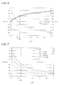
- Fig. 6 is a graph showing the result of comparing the operation force F and the operation force F 1 under an arbitrary condition.
- the horizontal axis of the graph represents a ratio of the distance L 2 from the attracting position S 1 to the operation position W with respect to the distance L 1 from the attracting position S 1 to the attracting position S 2 .
- the left vertical axis of the graph represents a ratio of the operation force F and the operation force F 1 with respect to the magnetic force f by the end 3, and the right vertical axis represents a ratio of the operation force F 1 with respect to the operation force F.
- the power generation device 10 in the first state merely requires the operation force of separating the armature 1 from the end 3a, and thus the operation force F 1 is expressed by the following equation.
- F 1 L 1 L 1 + L 2 ⁇ f
- the ratio of the operation force F 1 with respect to the operation force F is always smaller than 1. In other words, F 1 ⁇ F is met under the arbitrary condition. As shown on the left vertical axis of Fig. 6 , the ratio of the operation force F and the operation force F 1 with respect to the magnetic force f by the end 3 is always smaller for the operation force F 1 . As described above, since the distance L 1 is 15 mm and the distance L 2 is 10 mm in the present embodiment, the ratio shown on the horizontal axis becomes 10/15 ⁇ 0.67 (shown with a dotted line in Fig. 6 ). Since the value of the right vertical axis in this case is 0.7, the power generation device 10 in the first state can operate the armature 1 with the operation force of about 70 percent of that in the related art.
- Fig. 7 is a graph showing the result of comparing the operation force F and the operation force F 2 under an arbitrary condition.
- the horizontal axis of the graph represents a ratio of the distance L 2 with respect to the distance L 1 .
- the vertical axis of the graph represents a ratio of the operation force F and the operation force F 2 with respect to the magnetic force f by the end 3 when the ratio of the magnetic force f' (referring to magnetic force exerted by the end 3 when the armature 1 is not in contact with the end 3.
- the power generation device 10 in the second state requires the operation force of separating the armature 1 from the end 3c, and thus the operation force F 2 is expressed by the following equation.
- F 2 L 1 L 1 + 2 ⁇ L 2 ⁇ f + f ⁇
- the ratio of the operation force F 2 with respect to the magnetic force f by the end 3 is smaller than the ratio of the operation force F regardless of the ratio of the magnetic force f' with respect to the magnetic force f. Therefore, as expressed by the above equation, the ratio of the operation force F 2 with respect to the operation force F is always smaller than 1. In other words, F 2 ⁇ F is met under the arbitrary condition.
- Fig. 8 is a graph showing the change in the ratio of the magnetic force f' with respect to the magnetic force f of an arbitrary position from the end 3a to the end 3b (or from the end 3c to the end 3d).
- the horizontal axis of the graph represents the value in which the movement distance from the end 3a to the end 3b (or from the end 3c to the end 3d) is normalized to a range from -1 to 1.
- the position of the attracting position S 1 corresponds to -1
- the intermediate position between the attracting position S 1 and the attracting position S 3 corresponds to 0
- the position of the attracting position S 3 corresponds to 1.
- Fig. 8 shows most clearly that the magnetic force by one end (the end 3a or the end 3d) becomes weaker, and at the same time, the magnetic force by the other end (the end 3b or the end 3c) becomes stronger as the armature 1 separates from one attracting position (attracting position S 1 or attracting position S 2 ) and approaches the other attracting position (attracting position S 3 or attracting position S 4 ) as the movement distance shown by the horizontal axis increases.
- the magnetic force f' is equal to the magnetic force f where ratio of the magnetic force f' with respect to the magnetic force f is 1.
- the influence of the magnetic force f' non-linearly attenuates and becomes zero at the intermediate position between the attracting position S 1 and the attracting position S 3 , where magnetic forces by the opposing ends are balanced, as the armature 1 separates from the attracting position S 1 and approaches the attracting position S 3 when the movement distance increases. Furthermore, the influence of the magnetic force f' by the end 3a further non-linearly attenuates, where influence of the magnetic force f' by the end 3b further non-linearly increases, as the armature 1 separates from the attracting position S 1 and approaches the attracting position S 3 . At the position of the attracting position S 3 when the movement distance is one, the absolute value of the magnetic force f' becomes equal to the magnetic force f where the ratio of the magnetic force f' with respect to the magnetic force f is -1.
- the operation force F 3 for transitioning the power generation device 10 from the third state to fourth state is smaller than the operation force F required in the conventional power generation device.
- Fig. 9A is graph showing the result of comparing the operation force F and the operation force F 3 under an arbitrary condition
- Fig. 9B is a graph showing the condition in which the operation force F 3 becomes smaller than the operation force F.
- the horizontal axes of both graphs represent the ratio of the distance L 2 with respect to the distance L 1 .
- FIG. 9A represents the ratio of the operation force F and the operation force F 2 with respect to the magnetic force f by the end 3 when the ratio of the magnetic force f' with respect to the magnetic force f (see Fig. 8 ) takes each value
- the vertical axis of the graph of Fig. 9B represents the ratio of the magnetic force f' with respect to the magnetic force f.
- the ratio of the operation force F 3 with respect to the magnetic force f by the end 3 is smaller than the ratio of the operation force F (F 3 ⁇ F is met) under a weak condition.
- the weak condition for satisfying F 3 ⁇ F is expressed by the following inequality. f ⁇ f ⁇ 2 ⁇ L 2 L 1 + 2 ⁇ L 2
- the specification of the power generation device 10 is preferably determined so as to fall within the range shown in Fig. 9B .
- the condition of the specification is not strict. This is because (1) the design in which the distance L 2 becomes shorter than half the distance L 1 is a design that is rarely carried out; (2) the ratio of the magnetic force f' with respect to the magnetic force f becomes 0.5 limiting to a very special condition in which the armature 1 is in close contact with the end 3 (see Fig. 8 ), (3) the armature 1 that reached the intermediate position has kinetic momentum and the inertia of rotation acts, so that actually, the operation force smaller than the operation force F 3 expressed by the above equation is enough.
- the operation force greater than the sum of the magnetic forces by the two ends is not required all at once as in the conventional power generation device.
- the operation force greater than the magnetic forces by the respective ends merely needs to be exerted in order (with time difference) in the power generation device 10.
- the operation force acts on the attracting position S 1 (acting point) with the principle of leverage acting more advantageously than in the conventional power generation device.
- the power generation device 10 can generate power with the operation force smaller than the operation force required in the conventional power generation device with a simple mechanism without enlarging the device or extending the operation stroke. Since the power generation device 10 can generate power of the same amount as the power that can be generated by the conventional power generation device, the power generation device 10 capable of generating power with the operation force smaller than the related art can generate power at higher power generation efficiency than the conventional power generation device.
- Fig. 10A is a graph showing the result of comparing the operation force F 1 and the operation force F 2 under an arbitrary condition
- Fig. 10B is a graph showing the condition in which the operation force F 2 becomes smaller than the operation force F 1 .
- the power generation device 10 is preferably designed so that the specification falls within the range shown in Fig. 10B .
- Fig. 11A is a graph showing the result of comparing the operation force F 1 and the operation force F 3 under an arbitrary condition
- Fig. 11 B is a graph showing the condition in which the operation force F 3 becomes smaller than the operation force F 1 .
- the power generation device 10 is preferably designed so that the specification falls within the range shown in Fig. 11B .
- the power generation device 10 when the design of the power generation device 10 satisfies a predetermined condition, the power generation device can reduce the required operation force as the armature 1 rotates. Therefore, the power generation device 10 can generate power at higher power generation efficiency than the conventional power generation device.
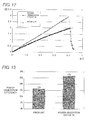
- Fig. 12 is a graph showing F-S characteristics of the power generation device 10 and the conventional power generation device.
- the horizontal axis of the graph represents the movement amount of the operation position W, and the vertical axis of the graph represents the force applied on the operation position.
- the armature 1 does not rotate, and the energy by the operation force is accumulated in the spring as the spring 4 having elasticity deflects. If the moment generated by the operation force F 1 becomes greater than the moment by the magnetic force of the end 3, the armature 1 rotates. In this case, the armature 1 accelerates the rotation by the energy accumulated in the spring 4.
- the operation force F 1 linearly increases in the former case over the range of 0 to 0.8 represented in the horizontal axis of the graph.
- the armature 1 separates from the end 3 and rotates, and a small amount of operation forces F 2 and F 3 are instantaneously measured in range of 0.8 to 1.0 of the horizontal axis of the graph.
- the operation force F 1 i.e., the height of the vertex of the graph
- the conventional power generation device requires the operation force F of 3N, whereas the power generation device 10 merely requires the operation force F 1 of 2N.
- the power generation device 10 can generate power with the operation force of smaller than or equal to 70 percent of that in the related art.
- the power generation device 10 can generate power with a simple operation involved in the daily performance without giving a sense of discomfort to the user or without the user being conscious of strongly pushing in the spring 4, as opposed to the conventional power generation device.
- Fig. 13 is a graph showing the power generation efficiency (i.e., the ratio of the power generation amount with respect to the energy accumulated in the spring 4) of the power generation device 10 and the conventional power generation device.
- the power generation efficiency of the conventional power generation device is only about 16%, whereas the power generation efficiency of the power generation device 10 reaches to above 27%.
- the power generation device 10 can improve the power generation efficiency of the conventional power generation device by 1.6 times.
- the power generation device 10 can suppress the operation force to lower than or equal to 70% of that in the related art while maintaining the power generation amount that can be generated by the conventional power generation device.
- the power generation device 10 can generate power at higher power generation efficiency than the conventional power generation device.
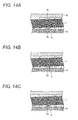
- Figs. 14A to 14C show variations of the modes of the protrusion 8a and the protrusion 8b.
- Fig. 14A is a cross-sectional view showing a case where the rectangular protrusion 8a and the rectangular protrusion 8b are respectively arranged on the spool 9b and the spool 9a;
- Fig. 14B is a cross-sectional view showing a case where only the rectangular protrusion 8a is arranged on the spool 9a;
- Fig. 14C is a cross-sectional view showing a case where the protrusion 8a with smoothened edge is arranged on the spool 9a.
- the shape of the protrusion 8a and the protrusion 8b may be a rectangle.
- the power generation device 10 can be simply manufactured since additional processing is not necessary.
- the protrusion 8b does not need to be arranged. Since further processing is not necessary, the power generation device 10 can be more simply manufactured, and furthermore, the manufacturing cost can be reduced.
- the area at which the armature 1 and the protrusion 8a make contact with each other can be made constant by smoothening the edge of the protrusion 8a.
- a situation can be avoided in which a load is intensively applied to only a specific portion of the armature 1 at a certain instant. Therefore, the shape of the protrusion 8a with smoothened edge can enhance the durability of the armature 1, and extend the durable years of the power generation device 10.
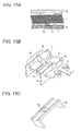
- Figs. 15A to 15C show a structure in which the protrusion 8a is supported by an elastic member that exerts stress.
- Fig. 15A is a cross-sectional view showing a state in which the elastic member supports the protrusion 8a;
- Fig. 15B is a bird's eye view of the power generation device 10 where the coil 6 is not shown; and
- Fig. 15C is a schematic view showing a structure of the spool 9b.
- the protrusion 8a may be supported by a spring (elastic member) 22.
- the armature 1 is pushed up by the stress of the spring 22 when the power generation device 10 transitions from the third state to the fourth state, thus accelerating the rotation of the armature 1. Therefore, the operation force F 3 may be further reduced, whereby the structure can further improve the power generation efficiency of the power generation device 10.
- the protrusion 8a is arranged on the spool 9a in the structure shown in Fig. 15A , but the protrusion 8b may be arranged on the spool 9b and may or may not be supported by a spring similar to the spring 22.
- an installing portion of the protrusion 8b may have a structure that can deflect up and down.
- the stress of the spring 22 is thereby further strengthened, and the structure can further improve the power generation efficiency of the power generation device 10.
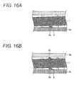
- Figs. 16A and 16B are views showing a structure in which the protrusion is arranged in the armature 1, where Fig. 16A is a cross-sectional view showing a structure in which the protrusion 8a is arranged only on the lower side of the armature 1, and Fig. 16B is a cross-sectional view showing a structure in which the protrusion 8a and the protrusion 8b are respectively arranged on both sides of the armature 1.
- a structure in which the protrusion 8a is arranged in the armature 1 may be adopted.
- the structure obtains effects similar to the structure in which the protrusion 8a is arranged on the spool 9a.
- a hard, soft magnetic material may be used for the protrusion 8a, in which case, the strength can be enhanced.
- the protrusion 8a and the protrusion 8b may be arranged on both sides of the armature 1.
- the risk can be avoided in which the armature 1 is attracted to both ends of one yoke and the armature 1 cannot rotate.
- the power generation device 10 can generate power not only when the operation position W is pushed down but also when the operation position W is pushed up.
- Fig. 17A is a cross-sectional view showing a structure in which a round shaft 28 arranged on a side surface of the armature 1 is supported by a bearing 29 of a long hole
- Fig. 17B is a cross-sectional view showing a structure in which a square shaft 28 arranged on a side surface of the armature 1 is supported by a protrusion 30a and a protrusion 30b respectively arranged on the spool 9a and the spool 9b.
- the shaft 28 arranged in the armature 1 is fitted into a vertically long hole 29 so that the shaft 28 moves up and down in the long hole 29. Accordingly, the above structure obtains effects similar to the structure in which the protrusion 8a is arranged on the spool 9a.
- a planar portion of the spool receives the load such that the armature 1 is supported by the shaft 28 at a wide area. Therefore, the above structure can enhance the durability of the armature 1, and extend the durable years of the power generation device 10.
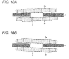
- FIG. 18A and 18B show a process in which the yoke 2a and the yoke 2b, and the permanent magnet 7 rotate, where Fig. 18A is a cross-sectional view showing an internal structure of the power generation device 10 when the power generation device 10 is in the first state, and Fig. 18B is a cross-sectional view showing the internal structure of the power generation device 10 when the power generation device 10 is in the fourth state.
- the power generation device 10 may have a configuration in which the yoke 2a, the yoke 2b, and the permanent magnet 7 rotate instead of the armature 1.
- the space at an interior of the bobbin partitioned by the spool 9a and the spool 9b does not need to be ensured for the armature 1 to rotate, and hence the coil 6 can be miniaturized.
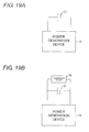
- Figs. 19A and 19B show electric machinery and apparatus that uses power generated by the power generation device 10.
- Fig. 19A is a circuit diagram showing a connection of a capacitor 21 to the power generation device 10
- Fig. 19B is a circuit diagram showing a connection of the capacitor 21 and a transmission device 20 to the power generation device 10.
- the capacitor 21 when the capacitor 21 is connected to the power generation device 10, the power generated by the power generation device can be accumulated in the capacitor.
- the transmission device 20 that transmits radio, infrared light, and the like to an external device using the power generated by the power generation device 10 may be connected.
- the power generation device 10 can operate the transmission device 20 that requires instantaneous power for a simple operation of transmitting radio, infrared light, and the like without using a power source such as a battery.
- Figs. 20A and 20B show electric machinery and apparatus that uses power generated by the power generation device 10.
- Fig. 20A is a schematic view showing a switch 100 including the power generation device 10, the capacitor 21, and the transmission device 20, and
- Fig. 20B is a schematic view showing a usage scene of the switch 100.
- the switch 100 includes the power generation device 10 and the capacitor 21, and is designed to be able to rotate the armature 1 of the power generation device 10 when the user pushes the switch 100.
- the switch 100 can be applied to a device for turning ON/OFF an indoor illumination device (fluorescent lamp or the like in the room).
- an indoor illumination device fluorescent lamp or the like in the room.
- such and ON/OFF switch is generally installed at the wall surface of the room, and the wiring connecting the switch and the indoor illumination device is embedded in the wall surface.
- the wiring does not need to be embedded in the wall surface as long as the indoor illumination device includes a device that can receive the signal transmitted by the transmission device 20.
- the power generation device 10 generates power by a daily operation of the user pushing the switch 100, and the transmission device 20 transmits a wireless signal to the indoor illumination device using the generated power, so that the indoor illumination device can be turned ON/OFF. Therefore, the switch 100 does not require construction work to embed the wiring.
- the switch 100 can reduce the cost required for the construction work, and furthermore, enables a free indoor layout that is not inhibited by the wiring.
- the application of the power generation device 10 is not limited to the application example described with reference to Figs. 19A and 19B and Figs. 20A and 20B , and application can be made to various other applications.
- the power generation device 10 can generate power with a smaller operation force than the operation force required in the conventional power generation device by a simple mechanism without enlarging the device or extending the operation stroke.
- the power generation device 10 can generate power of the same amount as the power that can be generated by the conventional power generation device, and thus the power generation device 10 capable of generating power with a smaller operation force than the related art has an effect of being able to generate power at higher power generation efficiency than the conventional power generation device.
- the present invention can be widely applied to a power generation device and the like for inducing current to the coil by the principle of electromagnetic induction.
Landscapes
- Engineering & Computer Science (AREA)
- Power Engineering (AREA)
- Connection Of Motors, Electrical Generators, Mechanical Devices, And The Like (AREA)
- Waste-Gas Treatment And Other Accessory Devices For Furnaces (AREA)
- Dynamo-Electric Clutches, Dynamo-Electric Brakes (AREA)
- Electromagnets (AREA)
Abstract
Description
- The present invention relates to a power generation device and the like for inducing current to a coil according to a principle of electromagnetic induction.
- A wide variety of applications is anticipated of a power generation device capable of generating power with a simple operation involved in daily performance. This is because the power generation device can operate small electric machinery and apparatus that requires instantaneous power for simple operation without a power source such as a battery. Therefore, the power generation device has been widely researched.
- For example,
US 2011/0285487 A (published November 24, 2011 ) discloses an electromagnetic energy converter, including two electromagnetic members and an electric coil, for converting machine energy to electric energy.JP 2009-516802 W (published April 23, 2009 - A structure of a conventional power generation device shown in
US 2011/0285487 A andJP 2009-516802 W Figs. 21A and 21 B. Figs. 21A and 21 B show an internal structure of the conventional power generation device, whereFig. 21A is a cross-sectional view when the power generation device is in an initial state, andFig. 21 B is a cross-sectional view when the power generation device is in a final state. - As shown in
Fig. 21A , aprotrusion 18a and aprotrusion 18b are respectively arranged in an extending manner on aspool 19a and aspool 19b with a central part C of anarmature 11 interposed therebetween. Thearmature 11 is attracted at attracting positions S1 and S2 by the magnetic force of anend 13a of ayoke 12a and anend 13c of a yoke 12b. Thearmature 11 is thus supported in an orientation of diagonally passing through a space defined by thespool 19a and thespool 19b. - As shown in
Fig. 21 B , when aspring 14 is pushed down at an operation position W, thearmature 11 rotates with the central part C as a supporting point. The direction of the magnetic flux of a permanent magnet changes so as to cooperatively operate with the rotation of thearmature 11 and hence the magnetic flux passing through acoil 16 fluctuates, so that the power generation device can induce current to the relevant coil. - The conventional power generation device still has a problem in that the operation force that needs to be applied on the operation position W is significantly large as compared to the force exerted by the daily performance. In other words, the conventional power generation device lacks in usability since the user feels a sense of discomfort if a force larger than usual is necessary or the user needs to be conscious of strongly pushing in the
spring 14. - A structural defect of the conventional power generation device causes the above problem. In other words, as shown in
Figs. 21A and 21 B , thearmature 11 always rotates with the central part C as the supporting point, and thus the conventional power generation device requires an operation force greater than the sum of the magnetic forces by the two ends (theend 13a and theend 13c inFig. 21A , the end 13b and theend 13d inFig. 21 B) . The sum of the magnetic forces is not large enough to cause problems in operating thearmature 11 but is large enough to an extent of causing the problems described above. - The simplest method for solving the above problems is to advantageously apply the principle of leverage by extending the distance from the central part C to the operation position W. However, such a method is not a preferred method since it enlarges the power generation device and newly causes problems of stretching the operation stroke, and the like.
- If a large operation force (or long operation stroke) is required for power generation under the condition of a constant power generation amount, this precisely means that the power generation efficiency is not satisfactory. The unsatisfactory power generation efficiency due to the structural defect may not be ignorable, not only in the application of causing the small electric machinery and apparatus to perform a simple operation, but also in other applications (e.g., application that requires continuous power generation of a certain extent, and the like).
- The present invention has been made in view of solving the problems described above, and an object thereof is to provide a power generation device and the like having higher power generation efficiency than the related art with a simple mechanism without enlarging the device or extending an operation stroke.
- To solve the problems described above, a power generation device is provided, including a rotation member configured to rotate by an externally applied operation force, and a supporting member configured to support the rotation member by attracting the rotation member with a magnetic force exerted at a predetermined portion of the supporting member, where the power generation device is configured to induce a current to a coil by causing a magnetic flux of a permanent magnet passing through the coil to fluctuate in cooperation with the rotation of the rotation member, and where when the operation force is applied in a first state in which the rotation member is supported by the supporting member by being attracted to a first portion and to a second portion of the supporting member at a respective first position and a second position of the supporting member, the rotation member transitions to a second state by rotating with the first position of the supporting member as a first supporting point, and further transitions to a third state by rotating with a position of the supporting member different from the first position as a second supporting point.
- As described above, in the conventional power generation device, the rotation member rotates with the central part thereof (portion between two protrusions) as the exclusive supporting point, and thus the operation force has to simultaneously act on the respective positions where the rotation member is attracted to the two ends. Thus, the conventional power generation device requires an operation force greater than the sum of the magnetic forces by the two ends, which may give a sense of discomfort to the user or may cause the user to be conscious of operating strongly.
- On the other hand, in the power generation device according to one aspect of the present invention, the rotation member transitions to the second state by rotating with the first position as the first supporting point when the operation force is applied in the first state. In other words, in the transition from the first state to the second state, the operation force acts only on the second position and thus the operation force merely needs to be a magnitude greater than the magnetic force by the second portion in the supporting member.
- Thereafter, the rotation member transitions to the third state by rotating with the position different from the first position as the second supporting point. In other words, in the transition from the second state to the third state, the operation force acts only on the first position and thus the operation force merely needs to be a magnitude greater than the magnetic force by the first portion. That is, the power generation device according to one aspect of the present invention does not require the operation force greater than the sum of the magnetic forces all at once as in the conventional power generation device, and requires only the operation force greater than the respective magnetic forces in order (with time difference).
- Therefore, the power generation device according to one aspect of the present invention can generate power with an operation force smaller than the operation force required in the conventional power generation device with a simple mechanism without enlarging the device or extending the operation stroke. The power generation device according to one aspect of the present invention can generate power of the same amount as the power that can be generated by the conventional power generation device, and thus can generate power at higher power generation efficiency than the conventional power generation device.
- In the power generation device according to one aspect of the present invention, (1) when supported by the supporting member with a space provided between the rotation member and a position to become the second supporting point in the first state, the rotation member may rotate with the first position as the first supporting point, and then rotate with the position different from the first position as the second supporting point, and (2) by the rotation, the rotation member may transition to the second state by acting the operation force on the second position in the first state, and then transition to the third state by acting the operation force on the first position.
- As described above, the conventional power generation device requires the operation force greater than the sum of the magnetic forces by the two ends. Since the rotation member rotates with the central part thereof (portion between two protrusions) as the exclusive supporting point, the operation force has to simultaneously act on the respective positions where the rotation member is attracted to the two ends.
- On the other hand, in the power generation device according to one aspect of the present invention, the rotation member and the position to become the second supporting point (e.g., central part of the rotation member) are not in contact with each other, and the rotation member is supported by the supporting member with a space provided between the rotation member and the position to become the second supporting point.
- Thus, after the rotation member rotates with the first position as the first supporting point so that the operation force acts on the second position (transition from the first state to the second state), the rotation member rotates with the position different from the first position as the second supporting point (transition from the second state to the third state). In other words, the power generation device according to one aspect of the present invention interchanges the supporting point of the rotation according to the position (the first position, the second position) to act the operation force without fixing the supporting point about which the rotation member rotates as in the conventional power generation device. Thus, the power generation device according to one aspect of the present invention does not require the operation force greater than the sum of the magnetic forces all at once as in the conventional power generation device, and requires only the operation force greater than the respective magnetic forces in order (with time difference).
- Therefore, the power generation device according to one aspect of the present invention can generate power with an operation force smaller than the operation force required in the conventional power generation device with a simple mechanism without enlarging the device or extending the operation stroke. The power generation device according to one aspect of the present invention thus can generate power of the same amount as the power that can be generated by the conventional power generation device, and hence can generate power at higher power generation efficiency than the conventional power generation device.
- In the power generation device according to one aspect of the present invention, (1) when the rotation member further rotates in the third state, the rotation member may further transition to a fourth state in which the rotation member is supported by the supporting member by being attracted to a third portion and a fourth portion in the supporting member at a third position and a fourth position with a space provided between the rotation member and the position to become the second supporting point.
- In the power generation device according to one aspect of the present invention, when the rotation member further rotates from the third state, the rotation member is supported by the supporting member in an orientation of being attracted to the third portion and the fourth portion in the supporting member (fourth state). In this case as well, the rotation member and the position to become the second supporting point (e.g., central part of the rotation member) are not in contact with each other, and the rotation member is supported with a space provided between the rotation member and the position to become the second supporting point. Thus, when the power generation device according to one aspect of the present invention transitions from the fourth state to the first state through the third state and the second state, the power generation device can interchange the supporting point of the rotation according to the position to act the operation force without fixing the supporting point about which the rotation member rotates as in the conventional power generation device.
- In other words, the power generation device according to one aspect of the present invention does not require the operation force greater than the sum of the magnetic forces all at once as in the conventional power generation device, and requires only the operation force greater than the respective magnetic forces in order (with time difference). Therefore, the power generation device according to one aspect of the present invention can generate power at higher power generation efficiency than in the related art with a simple mechanism without enlarging the device or extending the operation stroke.
- In the power generation device according to one aspect of the present invention, (1) a distance from the first position to a position to apply the operation force may be longer than a distance from the position to become the second supporting point to the position to apply the operation force.
- As described above, the power generation device according to one aspect of the present invention does not require the operation force greater than the sum of the magnetic forces all at once as in the conventional power generation device, and requires only the operation force greater than the respective magnetic forces in order (with time difference). In this case, the distance from the first supporting point to the position (force point) to apply the operation force is longer than the distance from the position to become the second supporting point to the operation position, and thus the operation force acts on the second position with the principle of leverage acting more advantageously than in the convention power generation device having the central part of the rotation member as the exclusive supporting point.
- Therefore, the power generation device can generate power with an operation force smaller than the operation force required in the conventional power generation device, and hence can generate power at higher power generation efficiency than in the conventional power generation device.
- In the power generation device according to one aspect of the present invention, (1) the rotation member may rotate with a protrusion as the second supporting point, the protrusion being arranged at a predetermined position of a fixing member configured to fix the supporting member.
- In other words, after the rotation member rotates with the first position as the first supporting point so that the operation force acts on the second position, the rotation member rotates with the position different from the first position as the second supporting point. In other words, the power generation device according to one aspect of the present invention interchanges the supporting point of the rotation according to the position to act the operation force without fixing the supporting point about which the rotation member rotates as in the conventional power generation device. Therefore, the power generation device according to one aspect of the present invention can generate power at higher power generation efficiency than in the related art with a simple mechanism without enlarging the device or extending the operation stroke.
- By way of example, the protrusion may be a rectangle. The power generation device described above can be easily manufactured since only simple processing is necessary (additional processing is not necessary). As another example, the protrusion may have a shape in which the rectangular edge is cut off. The area at which the rotation member and the protrusion make contact thus becomes constant, and a situation can be avoided in which the load is intensively applied to only a specific portion of the rotation member. Therefore, the shape of the protrusion with smoothened edge can enhance the durability of the rotation member and extend the durable years of the power generation device.
- In the power generation device according to one aspect of the present invention, (1) the protrusion arranged at the predetermined position of the fixing member may be supported by an elastic member that exerts stress.
- Thus, when the power generation device transitions the state of the operation, the stress of the elastic member accelerates the rotation of the rotation member. Therefore, the power generation device can generate power with an operation force smaller than the operation force required in the conventional power generation device, and hence can generate power at higher power generation efficiency than the conventional power generation device.
- The fixing member to which the protrusion is arranged may have a configuration that can deflect up and down. Thus, the stress of the elastic member is further strengthened, and the structure can further improve the power generation efficiency of the power generation device.
- To solve the problems described above, a transmission device according to another aspect of the present invention (1) is configured to transmit signals to an external device using power generated by the power generation device described above.
- In other words, the transmission device according to another aspect of the present invention is electrically connected with the power generation device, and the power required when transmitting the signal to the external device is provided by the power generated by the power generation device. Therefore, the transmission device according to another aspect of the present invention can transmit signals without mounting a power source such as a battery.
- To solve the problems described above, a switching device according to still another aspect of the present invention relates to (1) a switching device configured to switch states of an external device, (2) the switching device including the power generation device described above; and (3) the transmission device described above.
- The switching device according to still another aspect of the present invention can cause the transmission device to transmit signals to the external device using the power generated by the power generation device and cause the external device to receive the signals to switch the state of the external device without mounting the power source such as the battery. Thus, the wiring for connecting the switching device according to still another aspect of the present invention and the external device is not necessary, and the switching device can resolve all the demerits associated with the arrangement of the wiring.
- For example, the switching device can be applied as a device (electrical switch or the like) for switching ON/OFF of the external device such as the indoor illumination device. In this case, the wiring for connecting the switching device and the indoor illumination device does not need to be embedded in the wall surface, and thus the switching device not only reduces the cost, but also enables a free indoor layout that is not inhibited by the wiring.
- According to the power generation device of one aspect of the present invention, when the operation force is applied in the first state in which the rotation member is supported by the supporting member by being attracted to the first portion and the second portion in the supporting member at the first position and the second position, the rotation member rotates with the first position as the first supporting point to transition to the second state, and rotates with the position different from the first position as the second supporting point to further transition to the third state.
- Therefore, the power generation device according to one aspect of the present invention has an effect of being able to generate power at higher power generation efficiency than in the related art with a simple mechanism without enlarging the device or extending the operation stroke.
-
-
Fig. 1 is a cross-sectional view showing an internal structure of a power generation device according to one embodiment of the present invention when the power generation device is in a first state; -
Fig. 2 is a cross-sectional view showing the internal structure of the power generation device when the power generation device is in a second state; -
Fig. 3 is a cross-sectional view showing the internal structure of the power generation device when the power generation device is in a third state; -
Fig. 4 is a cross-sectional view showing the internal structure of the power generation device when the power generation device is in a fourth state; -
Figs. 5A to 5D are exploded perspective views each showing, in a step-wise manner, an assembly process of the power generation device, whereFig. 5A shows a first assembly process,Fig. 5B shows a second assembly process,Fig. 5C shows a third assembly process, andFig. 5D shows an outer appearance of the power generation device in which the assembly is completed; -
Fig. 6 is a graph showing the result of comparing an operation force F and an operation force F1 under an arbitrary condition; -
Fig. 7 is a graph showing the result of comparing the operation force F and an operation force F2 under an arbitrary condition; -
Fig. 8 is a graph showing the change in a ratio of a magnetic force f' with respect to a magnetic force f of an arbitrary position between the ends facing each other; -
Fig. 9A is graph showing the result of comparing the operation force F and an operation force F3 under an arbitrary condition, andFig. 9B is a graph showing the condition in which the operation force F3 becomes smaller than the operation force F; -
Fig. 10A is a graph showing the result of comparing the operation force F1 and the operation force F2 under an arbitrary condition, andFig. 10B is a graph showing the condition in which the operation force F2 becomes smaller than the operation force F1; -
Fig. 11A is a graph showing the result of comparing the operation force F1 and the operation force F3 under an arbitrary condition,Fig. 11 B is a graph showing the condition in which the operation force F3 becomes smaller than the operation force F1; -
Fig. 12 is a graph showing F-S characteristics of the power generation device and a conventional power generation device; -
Fig. 13 is a graph showing power generation efficiency of the power generation device and the conventional power generation device; -
Figs. 14A to 14C show variations of the modes of protrusions, whereFig. 14A is a cross-sectional view showing a case where a rectangular protrusion is arranged on each spool;Fig. 14B is a cross-sectional view showing a case where only the rectangular protrusion is arranged on the spool; andFig. 14C is a cross-sectional view showing a case where a protrusion with smoothened edge is arranged on the spool; -
Figs. 15A to 15C show a structure in which a shaft is supported by an elastic member that exerts stress, whereFig. 15A is a cross-sectional view showing a state in which the elastic member supports the shaft;Fig. 15B is a bird's eye view of the power generation device; andFig. 15C is a schematic view showing a structure of the spool; -
Figs. 16A and 16B are views showing a structure in which the protrusion is arranged in the armature, whereFig. 16A is a cross-sectional view showing a structure in which the protrusion is arranged only on a lower side of the armature, andFig. 16B is a cross-sectional view showing a structure in which the protrusions are respectively arranged on both sides of the armature; -
Fig. 17A is a cross-sectional view showing a structure in which a round shaft arranged on a side surface of the armature is supported by a bearing of a long hole, andFig. 17B is a cross-sectional view showing a structure in which a square shaft arranged on a side surface of the armature is supported by protrusions respectively arranged on the spool and the spool; -
Figs. 18A and 18B show a process in which yokes and a permanent magnet rotate, whereFig. 18A is a cross-sectional view showing an internal structure of the power generation device when the power generation device is in the first state, andFig. 18B is a cross-sectional view showing an internal structure of the power generation device when the power generation device is in the fourth state; -
Figs. 19A and 19B show electric machinery and apparatus that uses the power generated by the power generation device, whereFig. 19A is a circuit diagram showing a connection of a capacitor to the power generation device, andFig. 19B is a circuit diagram showing a connection of the capacitor and a transmission device to the power generation device; -
Figs. 20A and 20B show electric machinery and apparatus that uses power generated by the power generation device, whereFig. 20A is a schematic view showing a switch including the power generation device, the capacitor, and the transmission device, andFig. 20B is a schematic view showing a usage scene of the switch; and -
Figs. 21A and 21 B show an internal structure of a conventional power generation device, whereFig. 21A is a cross-sectional view when the power generation device is in an initial state, andFig. 21 B is a cross-sectional view when the power generation device is in a final state. - One embodiment of the present invention will be described in detail based on
Figs. 1 to 20B . - The configuration of a
power generation device 10 will be described based onFig. 1. Fig. 1 is a cross-sectional view showing an internal structure of the power generation device when thepower generation device 10 is in a first state. The relationship of the entirepower generation device 10 and the cross-section shown inFig. 1 will be described below with reference toFig. 5D . - The
power generation device 10 is a device that fluctuates the magnetic flux of a permanent magnet 7 (not shown in the cross-section ofFig. 1 , seeFig. 5B ) passing through acoil 6 so as to cooperatively operate with rotation of anarmature 1 to induce current to the coil. Thepower generation device 10 includes thearmature 1, ayoke 2a, ayoke 2b, aspring 4, thecoil 6, thepermanent magnet 7, aspool 9a, and aspool 9b. - The armature (rotation member) 1 is a member having a double hook shape (i.e., a shape in which two small plate-like members of the same shape are added to the side surface of a plate-like member so that both ends of the plate-like member have a substantially right angle hook shape), where long side portions of the double hook shape are mounted on the
spool 9a. Thespool 9b is placed so as to cover the long side portions, and thespool 9a and thespool 9b are fitted from top and bottom to form a cuboid portion E configured by covering the long side portions, where the cuboid portion is hereinafter referred to as "bobbin". Therefore, the widths of thespool 9a and thespool 9b are substantially the same as the lengths of the long side portions, and the hook shaped portions of thearmature 1 are extended from the bobbin so that a portion curved to a substantially right angle is exposed. - The
coil 6 is a member for retrieving current (electric energy) from a fluctuating magnetic field. Thecoil 6 is mounted on thespool 9b so as to cover the bobbin. A predetermined device (e.g., wireless device or the like, described in detail below) that uses the induced current is connected to both ends of thecoil 6 by way of an electric circuit. - The
spring 4 is fixed to one hook shaped portion of thearmature 1 by a fixingpin 5. Therefore, thearmature 1 operates inside the bobbin when an arbitrary operation position W in thespring 4 is pushed. The process in which thearmature 1 operates will be described in detail below with reference toFigs. 1 to 4 which illustrates a series of cross-sectional views showing the process of the relevant operation. - The yoke (supporting member) 2a and the yoke (supporting member) 2b are plate-like members. As will be described below, the yokes are formed by using a soft magnetic material, and thus the
yoke 2a and theyoke 2b themselves have properties of a magnet. Hereinafter, both ends of theyoke 2a are referred to as an end (second portion) 3a and an end (fourth portion) 3d, and both ends of theyoke 2b are referred to as an end (third portion) 3b and an end (first portion) 3c. Theyoke 2b and the spool (fixing member) 9a are fitted from top and bottom with theyoke 2b on the bottom and the spool (fixing member) 9a on the top. A short circular column shaped protrusion is formed substantially at the middle of theyoke 2b, and the permanent magnet is mounted on theyoke 2b with the protrusion fitted into a central part (referring to a hollow hole, the diameter of the hole being substantially the same as the diameter of the protrusion) of the doughnut-shaped (i.e., a shape in which the central part of the circular column is made hollow)permanent magnet 7. - A similar protrusion is also arranged substantially at the middle of the
yoke 2a. Theyoke 2a is mounted on thespool 9a with the protrusion fitted into the central part of thepermanent magnet 7 from above so as to sandwich thepermanent magnet 7 with theyoke 2a and theyoke 2b. In other words, thepermanent magnet 7 is sandwiched by the two yokes from the top and the bottom with the central part fixed by the protrusions respectively arranged in theyoke 2a and theyoke 2b, and the three sides surrounded by the bobbin and the two hook-shaped portions of thearmature 1. Thepermanent magnet 7 is therefore not shown in the cross-sectional view ofFig. 1 . - Both ends of the
yoke 2a and theyoke 2b are extended from thespool 9a, and are positioned to sandwich the ends of the hook shaped portions of thearmature 1 from the top and bottom. A spacing (substantially equal to the thickness of the permanent magnet 7) between theyoke 2a and theyoke 2b is greater than the thickness of thearmature 1, and thus the ends of the hook shaped portions of thearmature 1 are not sandwiched by the ends of the yokes. - The magnetic force by the
ends 3a to 3d of theyoke 2a and theyoke 2b act to attract the ends of the hook shaped portions of thearmature 1. Inside the bobbin, aprotrusion 8a and aprotrusion 8b are arranged in an extending manner on thespool 9a and thespool 9b in the width direction of the long side portions of the double hook shape of thearmature 1. Thus, thearmature 1 is inhibited from being attracted to both ends of one yoke, whereby thearmature 1 is constantly supported in an orientation of diagonally passing through the interior of the bobbin by the magnetic force of the ends positioned diagonally with respect to each other with thearmature 1 therebetween. - As shown in
Fig. 1 , a state in which thearmature 1 is supported inside the bobbin in the above orientation is hereinafter referred to as a "first state". Theprotrusion 8b merely prevents thearmature 1 from being attracted to theend 3a and theend 3d of theyoke 2a, and is not directly related to the operation of thearmature 1 to be described below. Therefore, theprotrusion 8b may not be arranged in an extending manner on thespool 9b. - Furthermore, the surfaces of the respective ends where the
ends 3a to 3d make contact with thearmature 1 have an angle substantially equal to an angle formed by the orientation of thearmature 1 with respect to the surface of the interior of the bobbin. Thus, the respective ends and thearmature 1 make contact at the surface and thearmature 1 does not make contact with the respective ends at the corner of the respective ends. Here, the center of a surface where thearmature 1 is attracted to theend 3a is an attracting position (second position) S1, the center of a surface where thearmature 1 is attracted to theend 3c is an attracting position (first position) S2, the center of a surface where thearmature 1 is attracted to theend 3b is an attracting position (third position) S3, and the center of a surface where thearmature 1 is attracted to theend 3d is an attracting position (fourth position) S4 (seeFig. 4 ). - In the first state, the
armature 1 and theprotrusion 8a do not come into contact with each other, and thus a space (hereinafter referred to as "clearance A") is formed between thearmature 1 and theprotrusion 8a from the distal end of theprotrusion 8a to the surface of thearmature 1 in a perpendicularly upward direction. Therefore, when thespring 4 is pushed down at an arbitrary operation position W, thearmature 1 starts to rotate in a direction such that thearmature 1 approaches theend 3b from theend 3a, with the attracting position S2 as the supporting point, not theprotrusion 8a. In other words, as opposed to the conventional structure (seeFigs. 21A and 21 B ) in which the clearance A does not exist and the armature constantly rotates with the central part of the armature as the supporting point, the central part C of thearmature 1 rotates with the operation position W. - Thus, an operation force greater than the sum of the magnetic forces by the two ends is not necessary as in the conventional power generation device, and an operation force greater than the respective magnetic forces merely needs to be exerted (with time difference) in the
power generation device 10. In this case, a distance (L1 + L2) from the attracting position S2 (supporting point) to the operation position W (force point) is longer than a distance (L1/2 + L2) from the central part C to the operation position W. Thus, the operation force acts on the attracting position S1 (acting point) in a state where the principle of leverage is acting more advantageously than in the conventional power generation device. - Therefore, the
power generation device 10 can generate power with a smaller operation force than the operation force required in the conventional power generation device with a simple mechanism without enlarging the device or extending the operation stroke. Since thepower generation device 10 can generate power of the same amount as the power that can be generated by the conventional power generation device, thepower generation device 10 capable of generating power with smaller operation force than the related art can generate power at higher power generation efficiency than the conventional power generation device. - The
armature 1 is made using a soft magnetic material such as permalloy, pure iron (e.g., SUY-0), and the like. In the present embodiment, thearmature 1 has a dimension of 8 mm vertically, 20 mm horizontally, and 1.4 mm in thickness. However, such dimension is merely illustrative for the sake of explanation, and can be arbitrarily changed depending on the dimension of thepower generation device 10. - The
yoke 2a and theyoke 2b are made using a soft magnetic material such as permalloy, pure iron (e.g., SUY-0), and the like. In the present embodiment, the distance in the perpendicular direction (distance in the vertical direction in the cross-sectional view shown inFig. 1 ) from the attracting position S1 to the attracting position S2 is 2.0 mm so that the movable angle of the armature 1 (i.e., the angle formed by the orientation of thearmature 1 diagonally passing through the interior of the bobbin with respect to the surface of the interior of the bobbin) becomes about 3.2°, and thus the spacing between theyoke 2a and theyoke 2b is obtained in accordance with the distance in the perpendicular direction. However, similar to the dimension of thearmature 1, the movable angle and the spacing are both arbitrarily changeable. In the present embodiment, theyoke 2a, theyoke 2b, and thespring 4 respectively have appropriate dimensions such that the distance L1 from the attracting position S1 to the attracting position S2 becomes 15 mm, and the distance L2 from the attracting position S1 to the operation position W becomes 10 mm. - The
spring 4 is made using a non-magnetic material such as stainless steel (SUS). The elasticity of thespring 4 facilitates the rotation of thearmature 1. This is because when thearmature 1 starts to rotate away from the attraction of theend 3a, the stress of thespring 4 accelerates the rotation of the armature. - The spool 9 is made using resin such as polycarbonate (PC), polybutylene terephthalate (PBT), ABS (collective term of Acrylonitrile, Butadiene, Styrene copolymer synthetic resin) or a non-magnetic metal such as copper. If the
armature 1 has the dimension of one example described above, the spacing between thespool 9a and thespool 9b is set to 2.0 mm so that the size of the clearance A becomes 0.2 mm. However, the spacing can be arbitrarily changed, similar to the dimension of thearmature 1. - If the
armature 1 has the dimension of one example described above, the height of theprotrusion 8a may be 0.2 mm, for example. - The process in which the
power generation device 10 operates will be described based onFigs. 1 to 4 . As described with reference toFig. 1 , if thepower generation device 10 is in the first state, thearmature 1 starts to rotate with the attracting position (first position) S2 as the supporting point (first supporting point) when thespring 4 is pushed down at the arbitrary operation position W. This is because in the first state, thearmature 1 and theprotrusion 8a are not in contact with each other such that the clearance A exists, and the central part C accordingly rotates with the operation position W. -
Fig. 2 is a cross-sectional view showing an internal structure of the power generation device when thepower generation device 10 is in a second state. As shown inFig. 2 , when the operation force applied on the operation position W becomes greater than the magnetic force fixing thearmature 1, and thearmature 1 rotates away from theend 3a, the armature makes contact with theprotrusion 8a at the central part C. Thus, thearmature 1 starts to rotate with theprotrusion 8a as the supporting point (i.e., the second supporting point). The state shown inFig. 2 is hereinafter referred to as "second state". -
Fig. 3 is a cross-sectional view showing an internal structure of the power generation device when thepower generation device 10 is in a third state. As shown inFig. 3 , when thearmature 1 is further rotated from the second state, the armature is attracted to theend 3b at the attracting position S3. When the force for rotating thearmature 1 becomes greater than the magnetic force by theend 3c, the armature separates away from theend 3c and further rotates. The state shown inFig. 3 is hereinafter referred to as the "third state". -
Fig. 4 is a cross-sectional view showing an internal structure of the power generation device when thepower generation device 10 is in a fourth state. As shown inFig. 4 , when thearmature 1 further rotates from the third state, thearmature 1 separates away from theprotrusion 8a (clearance A is formed) and rotates with the attracting position S3 as the supporting point by the inertia caused by the rotation, the magnetic force by theend 3d, and the operation force applied on the operation position W. In other words, the central part C rotates with a left end portion D of thearmature 1. Finally, thearmature 1 is attracted to theend 3d at the attracting position S4. Thus, thearmature 1 is supported in an orientation of passing through the bobbin diagonally opposite to the first state. The state shown inFig. 4 is hereinafter referred to as the "fourth state". - As described above with reference to
Figs. 1 to 4 , due to the existence of the clearance A, the supporting point of the rotation is interchanged between the attracting position S2 or S3 and theprotrusion 8a in the process of the operation, and thepower generation device 10 transitions from the first state to the fourth state. Accompanied therewith, the magnetic flux of thepermanent magnet 7 fluctuates, and the power generation device can induce current to thecoil 6. - Above, description is provided in which the
power generation device 10 transitions from the first state to the fourth state through the second state and third state. On the other hand, thepower generation device 10 can transition from the fourth state to the first state through the second state and the third state. In this case as well, due to the existence of the clearance A, the supporting point of the rotation is interchanged between the attracting position S2 or S3 and theprotrusion 8a in the process of the operation, similar to above. It should be noted that, when transition is made from the fourth state to the first state, the process of the operation changes according to the position of acting the operation force. For example, if the operation force is applied upward on the operation position W, the supporting point of the rotation is interchanged between the attracting position S2 or S3 and theprotrusion 8b (not theprotrusion 8a) in the process of the operation. Thus, even when the transition is made from the fourth state to the first state, thepower generation device 10 has the effect of being able to generate power at higher power generation efficiency than the conventional power generation device, similar to when the transition is made from the first state to the fourth state. - The outer appearance and the assembly process of the
power generation device 10 will be described based onFigs. 5A to 5D. Figs. 5A to 5D are exploded perspective views each showing, in a step-wise manner, an assembly process of thepower generation device 10, whereFig. 5A shows a first assembly process,Fig. 5B shows a second assembly process,Fig. 5C shows a third assembly process, andFig. 5D shows an outer appearance of thepower generation device 10 in which the assembly is completed.Figs. 1 to 4 described above correspond to the cross-sectional views taken along line B-B inFig. 5D . - The
power generation device 10 is assembled as shown inFigs. 5A to 5D . In other words, in the first assembly process, thespring 4 is fixed to thearmature 1 by the fixingpin 5, the long side portion of the armature is mounted on thespool 9a, and thespool 9a and thespool 9b are fitted from the top and bottom (seeFig. 5A ). Then, in the second assembly process, thepermanent magnet 7 is mounted on theyoke 2b, theyoke 2b andspool 9a are fitted from the top and bottom, and theyoke 2a is mounted on thespool 9a (seeFigs. 5B and 5C ). Lastly, in the third assembly process, thecoil 6 is mounted on thespool 9b (seeFig. 5D ). - As described above, the
permanent magnet 7 is fixed while being sandwiched by theyoke 2a and theyoke 2b. The magnetic flux of thepermanent magnet 7 is generated in the clockwise direction in the first state, and the magnetic flux is generated in the counterclockwise direction in the fourth state. In other words, the magnetic flux of thepermanent magnet 7 fluctuates by the transition from the first state to the fourth state. Notably, the magnetic flux fluctuates between the first state and the fourth state, regardless of the rotating direction. Therefore, thepower generation device 10 can induce current to thecoil 6 by the rotation of thearmature 1. - As described herein below with reference to
Fig. 6 , the operation force F1 for making thepower generation device 10 transition from the first state to the second state is smaller than the operation force F required in the conventional power generation device.Fig. 6 is a graph showing the result of comparing the operation force F and the operation force F1 under an arbitrary condition. The horizontal axis of the graph represents a ratio of the distance L2 from the attracting position S1 to the operation position W with respect to the distance L1 from the attracting position S1 to the attracting position S2. The left vertical axis of the graph represents a ratio of the operation force F and the operation force F1 with respect to the magnetic force f by theend 3, and the right vertical axis represents a ratio of the operation force F1 with respect to the operation force F. - As described above, in the conventional power generation device of
Figures 21A and 21 B , an operation force is required that is greater than the sum of the magnetic forces of the respective ends 13a and 13c and theends 13b and 13d. Accordingly, the operation force F is expressed by the following equation.
- The
power generation device 10 in the first state (seeFig. 1 ) merely requires the operation force of separating thearmature 1 from theend 3a, and thus the operation force F1 is expressed by the following equation.
- Therefore, the ratio of the operation force F1 to the operation force F is expressed by the following equation.

- As shown on the right vertical axis of
Fig. 6 and the above equation, the ratio of the operation force F1 with respect to the operation force F is always smaller than 1. In other words, F1 < F is met under the arbitrary condition. As shown on the left vertical axis ofFig. 6 , the ratio of the operation force F and the operation force F1 with respect to the magnetic force f by theend 3 is always smaller for the operation force F1. As described above, since the distance L1 is 15 mm and the distance L2 is 10 mm in the present embodiment, the ratio shown on the horizontal axis becomes 10/15 ≈ 0.67 (shown with a dotted line inFig. 6 ). Since the value of the right vertical axis in this case is 0.7, thepower generation device 10 in the first state can operate thearmature 1 with the operation force of about 70 percent of that in the related art. - As now discussed with respect to
Fig. 7 , the operation force F2 for making thepower generation device 10 transition from the second state to the third state is smaller than the operation force F required in the conventional power generation device.Fig. 7 is a graph showing the result of comparing the operation force F and the operation force F2 under an arbitrary condition. The horizontal axis of the graph represents a ratio of the distance L2 with respect to the distance L1. The vertical axis of the graph represents a ratio of the operation force F and the operation force F2 with respect to the magnetic force f by theend 3 when the ratio of the magnetic force f' (referring to magnetic force exerted by theend 3 when thearmature 1 is not in contact with theend 3. - To further rotate the
armature 1 with theprotrusion 8a as the supporting point, thepower generation device 10 in the second state (seeFig. 2 ) requires the operation force of separating thearmature 1 from theend 3c, and thus the operation force F2 is expressed by the following equation.
- Therefore, the ratio of the operation force F2 with respect to the operation force F is expressed by the following equation.

- As shown on the vertical axis of
Fig. 7 , the ratio of the operation force F2 with respect to the magnetic force f by theend 3 is smaller than the ratio of the operation force F regardless of the ratio of the magnetic force f' with respect to the magnetic force f. Therefore, as expressed by the above equation, the ratio of the operation force F2 with respect to the operation force F is always smaller than 1. In other words, F2 < F is met under the arbitrary condition. Furthermore, since the value of the vertical axis (F2/f, f'/f = -0.1) is 0.39 when the ratio represented by the horizontal axis is 0.67, thepower generation device 10 in the second state can operate thearmature 1 with an operation force smaller than or equal to half of that in the related art (F/f = 0.85). - The influence of the magnetic force by the pairs of ends (3a and 3b, and 3c and 3d) facing each other will be described based on
Fig. 8. Fig. 8 is a graph showing the change in the ratio of the magnetic force f' with respect to the magnetic force f of an arbitrary position from theend 3a to theend 3b (or from theend 3c to theend 3d). The horizontal axis of the graph represents the value in which the movement distance from theend 3a to theend 3b (or from theend 3c to theend 3d) is normalized to a range from -1 to 1. In other words, the position of the attracting position S1 corresponds to -1, the intermediate position between the attracting position S1 and the attracting position S3 corresponds to 0, and the position of the attracting position S3 corresponds to 1. -
Fig. 8 shows most clearly that the magnetic force by one end (theend 3a or theend 3d) becomes weaker, and at the same time, the magnetic force by the other end (theend 3b or theend 3c) becomes stronger as thearmature 1 separates from one attracting position (attracting position S1 or attracting position S2) and approaches the other attracting position (attracting position S3 or attracting position S4) as the movement distance shown by the horizontal axis increases. In other words, at the position of the attracting position S1 when the movement distance is -1, the magnetic force f' is equal to the magnetic force f where ratio of the magnetic force f' with respect to the magnetic force f is 1. - The influence of the magnetic force f' non-linearly attenuates and becomes zero at the intermediate position between the attracting position S1 and the attracting position S3, where magnetic forces by the opposing ends are balanced, as the
armature 1 separates from the attracting position S1 and approaches the attracting position S3 when the movement distance increases. Furthermore, the influence of the magnetic force f' by theend 3a further non-linearly attenuates, where influence of the magnetic force f' by theend 3b further non-linearly increases, as thearmature 1 separates from the attracting position S1 and approaches the attracting position S3. At the position of the attracting position S3 when the movement distance is one, the absolute value of the magnetic force f' becomes equal to the magnetic force f where the ratio of the magnetic force f' with respect to the magnetic force f is -1. - In the above description of
Fig. 7 , the reason for focusing on the ratio of the operation force F2 with respect to the magnetic force f by theend 3 in f'/f = -0.1 (position shown with a horizontal dotted line inFig. 8 ) is that thearmature 1 normally separates from theend 3c (i.e., critical point of the second state and the third state) at the position where the movement distance becomes about 0.6 (position shown with a vertical dotted line inFig. 8 ). - As now discussed with regard to
Figs. 9A and 9B , the operation force F3 for transitioning thepower generation device 10 from the third state to fourth state is smaller than the operation force F required in the conventional power generation device.Fig. 9A is graph showing the result of comparing the operation force F and the operation force F3 under an arbitrary condition, andFig. 9B is a graph showing the condition in which the operation force F3 becomes smaller than the operation force F. The horizontal axes of both graphs represent the ratio of the distance L2 with respect to the distance L1. The vertical axis of the graph ofFig. 9A represents the ratio of the operation force F and the operation force F2 with respect to the magnetic force f by theend 3 when the ratio of the magnetic force f' with respect to the magnetic force f (seeFig. 8 ) takes each value, and the vertical axis of the graph ofFig. 9B represents the ratio of the magnetic force f' with respect to the magnetic force f. - To further rotate the
armature 1 with theprotrusion 8a as the supporting point, the operation force F3 required by thepower generation device 10 in the third state (seeFig. 3 ) is expressed by the following equation.
- Therefore, the ratio of the operation force F3 with respect to the operation force F is expressed by the following equation.

- As shown in
Fig. 9A , the ratio of the operation force F3 with respect to the magnetic force f by theend 3 is smaller than the ratio of the operation force F (F3 < F is met) under a weak condition. The weak condition for satisfying F3 < F is expressed by the following inequality.
-
Fig. 9B shows a range satisfying the above inequality, the lower side portion of the curve indicating F3 = F. The specification of thepower generation device 10 is preferably determined so as to fall within the range shown inFig. 9B . In the actual design, the condition of the specification is not strict. This is because (1) the design in which the distance L2 becomes shorter than half the distance L1 is a design that is rarely carried out; (2) the ratio of the magnetic force f' with respect to the magnetic force f becomes 0.5 limiting to a very special condition in which thearmature 1 is in close contact with the end 3 (seeFig. 8 ), (3) thearmature 1 that reached the intermediate position has kinetic momentum and the inertia of rotation acts, so that actually, the operation force smaller than the operation force F3 expressed by the above equation is enough. - For example, since the value of the vertical axis (F3/f, f'/f = 0.1) is 0.2 when the ratio represented by the horizontal axis becomes 0.67, the
power generation device 10 in the third state can operate thearmature 1 with the operation force of about 20 percent of that in the related art (F/f = 0.85). - Therefore, the operation force greater than the sum of the magnetic forces by the two ends is not required all at once as in the conventional power generation device. In other words, the operation force greater than the magnetic forces by the respective ends merely needs to be exerted in order (with time difference) in the
power generation device 10. In this case, since the distance from the attracting position S2 to the operation position W is longer than the distance from the central part C to the operation position W, the operation force acts on the attracting position S1 (acting point) with the principle of leverage acting more advantageously than in the conventional power generation device. - Therefore, the
power generation device 10 can generate power with the operation force smaller than the operation force required in the conventional power generation device with a simple mechanism without enlarging the device or extending the operation stroke. Since thepower generation device 10 can generate power of the same amount as the power that can be generated by the conventional power generation device, thepower generation device 10 capable of generating power with the operation force smaller than the related art can generate power at higher power generation efficiency than the conventional power generation device. - Referring to
Figures 10A and 10B it will now be discussed that the operation force F2 is smaller than the operation force F1.Fig. 10A is a graph showing the result of comparing the operation force F1 and the operation force F2 under an arbitrary condition, andFig. 10B is a graph showing the condition in which the operation force F2 becomes smaller than the operation force F1. - As shown in
Fig. 10A , as the ratio of the magnetic force f' with respect to the magnetic force f becomes smaller, as thearmature 1 separates from theend 3a, the operation force F2 tends to become smaller than the operation force F1 (F2 < F2 is easily met) at the arbitrary distances L1, L2. In other words, the required operation force becomes smaller as thearmature 1 is further pushed in. As described above, since the operation force F2 is always smaller than the operation force F (F2 < F is met, seeFig. 7 and the equation 5), it should be recognized that the operation force F2 is smaller than the operation force F even if the operation force F2 becomes greater than the operation force F1 (if F2 > F1 is met). - The condition in which the operation force F2 becomes smaller than the operation F1 is expressed by the following equation.

-
Fig. 10B shows the range satisfying the above inequality where the lower side portion of the curve illustrates F2 = F1. In one embodiment, thepower generation device 10 is preferably designed so that the specification falls within the range shown inFig. 10B . - As discussed herein with regard to
Figures 11A and 11 B , the operation force F3 is smaller than the operation force F1.Fig. 11A is a graph showing the result of comparing the operation force F1 and the operation force F3 under an arbitrary condition,Fig. 11 B is a graph showing the condition in which the operation force F3 becomes smaller than the operation force F1. - As shown in
Fig. 11A , as the ratio of the magnetic force f' with respect to the magnetic force f becomes smaller, as thearmature 1 separates from theend 3a, the operation force F3 tends to become smaller than the operation force F1 (F3 < F1 is easily met) at the arbitrary distances L1, L2. In other words, the required operation force becomes smaller as thearmature 1 is further pushed in, similar to the description made above. - The condition in which the operation force F3 becomes smaller than the operation force F1 is expressed by the following equation.

- As shown in
Fig. 11 B , the range satisfying the above inequality is shown where the lower side portion of the curved line illustrates F3= F1. In one embodiment, thepower generation device 10 is preferably designed so that the specification falls within the range shown inFig. 11B . - Accordingly, when the design of the
power generation device 10 satisfies a predetermined condition, the power generation device can reduce the required operation force as thearmature 1 rotates. Therefore, thepower generation device 10 can generate power at higher power generation efficiency than the conventional power generation device. - With reference to
Fig. 12 , the comparison will now be discussed between the operation force required for the operation of thepower generation device 10 and the operation force required for the operation of the conventional power generation device.Fig. 12 is a graph showing F-S characteristics of thepower generation device 10 and the conventional power generation device. The horizontal axis of the graph represents the movement amount of the operation position W, and the vertical axis of the graph represents the force applied on the operation position. - If the moment generated by the operation force F1 is smaller than the moment by the magnetic force of the
end 3 or is balanced with such moment, thearmature 1 does not rotate, and the energy by the operation force is accumulated in the spring as thespring 4 having elasticity deflects. If the moment generated by the operation force F1 becomes greater than the moment by the magnetic force of theend 3, thearmature 1 rotates. In this case, thearmature 1 accelerates the rotation by the energy accumulated in thespring 4. - As shown in
Fig. 12 , the operation force F1 linearly increases in the former case over the range of 0 to 0.8 represented in the horizontal axis of the graph. In the latter case, thearmature 1 separates from theend 3 and rotates, and a small amount of operation forces F2 and F3 are instantaneously measured in range of 0.8 to 1.0 of the horizontal axis of the graph. Thus, the operation force F1 (i.e., the height of the vertex of the graph) dominantly influences the overall operation force (F1 + F2 + F3) in the operation of thepower generation device 10. - The conventional power generation device requires the operation force F of 3N, whereas the
power generation device 10 merely requires the operation force F1 of 2N. In other words, thepower generation device 10 can generate power with the operation force of smaller than or equal to 70 percent of that in the related art. In other words, thepower generation device 10 can generate power with a simple operation involved in the daily performance without giving a sense of discomfort to the user or without the user being conscious of strongly pushing in thespring 4, as opposed to the conventional power generation device. - A comparison of the power generation efficiency of the
power generation device 10 and the power generation efficiency of the conventional power generation device will be described based onFig. 13. Fig. 13 is a graph showing the power generation efficiency (i.e., the ratio of the power generation amount with respect to the energy accumulated in the spring 4) of thepower generation device 10 and the conventional power generation device. - As shown in
Fig. 13 , the power generation efficiency of the conventional power generation device is only about 16%, whereas the power generation efficiency of thepower generation device 10 reaches to above 27%. In other words, thepower generation device 10 can improve the power generation efficiency of the conventional power generation device by 1.6 times. Thepower generation device 10 can suppress the operation force to lower than or equal to 70% of that in the related art while maintaining the power generation amount that can be generated by the conventional power generation device. Thus, thepower generation device 10 can generate power at higher power generation efficiency than the conventional power generation device. - Other modes and structures of the
protrusion 8a and theprotrusion 8b will be described based onFigs. 14A to 17B .Figs. 14A to 14C show variations of the modes of theprotrusion 8a and theprotrusion 8b.Fig. 14A is a cross-sectional view showing a case where therectangular protrusion 8a and therectangular protrusion 8b are respectively arranged on thespool 9b and thespool 9a;Fig. 14B is a cross-sectional view showing a case where only therectangular protrusion 8a is arranged on thespool 9a; andFig. 14C is a cross-sectional view showing a case where theprotrusion 8a with smoothened edge is arranged on thespool 9a. - As shown in
Fig. 14A , the shape of theprotrusion 8a and theprotrusion 8b may be a rectangle. Thepower generation device 10 can be simply manufactured since additional processing is not necessary. - As shown in
Fig. 14B , if the operation forces F1 to F3 are constantly applied downward in the perpendicular direction (direction of pushing down the spring 4), theprotrusion 8b does not need to be arranged. Since further processing is not necessary, thepower generation device 10 can be more simply manufactured, and furthermore, the manufacturing cost can be reduced. - As shown in
Fig. 14C , the area at which thearmature 1 and theprotrusion 8a make contact with each other can be made constant by smoothening the edge of theprotrusion 8a. In other words, a situation can be avoided in which a load is intensively applied to only a specific portion of thearmature 1 at a certain instant. Therefore, the shape of theprotrusion 8a with smoothened edge can enhance the durability of thearmature 1, and extend the durable years of thepower generation device 10. -
Figs. 15A to 15C show a structure in which theprotrusion 8a is supported by an elastic member that exerts stress.Fig. 15A is a cross-sectional view showing a state in which the elastic member supports theprotrusion 8a;Fig. 15B is a bird's eye view of thepower generation device 10 where thecoil 6 is not shown; andFig. 15C is a schematic view showing a structure of thespool 9b. - As shown in
Fig. 15A , theprotrusion 8a may be supported by a spring (elastic member) 22. In this structure, thearmature 1 is pushed up by the stress of thespring 22 when thepower generation device 10 transitions from the third state to the fourth state, thus accelerating the rotation of thearmature 1. Therefore, the operation force F3 may be further reduced, whereby the structure can further improve the power generation efficiency of thepower generation device 10. Note that only theprotrusion 8a is arranged on thespool 9a in the structure shown inFig. 15A , but theprotrusion 8b may be arranged on thespool 9b and may or may not be supported by a spring similar to thespring 22. - As shown in
Figs. 15B and 15C , an installing portion of theprotrusion 8b (or theprotrusion 8a) may have a structure that can deflect up and down. The stress of thespring 22 is thereby further strengthened, and the structure can further improve the power generation efficiency of thepower generation device 10. -
Figs. 16A and 16B are views showing a structure in which the protrusion is arranged in thearmature 1, whereFig. 16A is a cross-sectional view showing a structure in which theprotrusion 8a is arranged only on the lower side of thearmature 1, andFig. 16B is a cross-sectional view showing a structure in which theprotrusion 8a and theprotrusion 8b are respectively arranged on both sides of thearmature 1. - As shown in
Fig. 16A , a structure in which theprotrusion 8a is arranged in thearmature 1 may be adopted. The structure obtains effects similar to the structure in which theprotrusion 8a is arranged on thespool 9a. Furthermore, a hard, soft magnetic material may be used for theprotrusion 8a, in which case, the strength can be enhanced. - As shown in
Fig. 16B , theprotrusion 8a and theprotrusion 8b may be arranged on both sides of thearmature 1. Thus, the risk can be avoided in which thearmature 1 is attracted to both ends of one yoke and thearmature 1 cannot rotate. Furthermore, thepower generation device 10 can generate power not only when the operation position W is pushed down but also when the operation position W is pushed up. -
Fig. 17A is a cross-sectional view showing a structure in which around shaft 28 arranged on a side surface of thearmature 1 is supported by a bearing 29 of a long hole, andFig. 17B is a cross-sectional view showing a structure in which asquare shaft 28 arranged on a side surface of thearmature 1 is supported by aprotrusion 30a and aprotrusion 30b respectively arranged on thespool 9a and thespool 9b. - As shown in
Fig. 17A , in the above structure, theshaft 28 arranged in thearmature 1 is fitted into a verticallylong hole 29 so that theshaft 28 moves up and down in thelong hole 29. Accordingly, the above structure obtains effects similar to the structure in which theprotrusion 8a is arranged on thespool 9a. - As shown in
Fig. 17B , in the above structure, a planar portion of the spool receives the load such that thearmature 1 is supported by theshaft 28 at a wide area. Therefore, the above structure can enhance the durability of thearmature 1, and extend the durable years of thepower generation device 10. - An embodiment in which the
yoke 2a and theyoke 2b, and thepermanent magnet 7 rotate instead of thearmature 1 will be described based onFigs. 18A and 18B. Figs. 18A and 18B show a process in which theyoke 2a and theyoke 2b, and thepermanent magnet 7 rotate, whereFig. 18A is a cross-sectional view showing an internal structure of thepower generation device 10 when thepower generation device 10 is in the first state, andFig. 18B is a cross-sectional view showing the internal structure of thepower generation device 10 when thepower generation device 10 is in the fourth state. - As shown in
Figs. 18A and 18B , thepower generation device 10 may have a configuration in which theyoke 2a, theyoke 2b, and thepermanent magnet 7 rotate instead of thearmature 1. In such a structure, the space at an interior of the bobbin partitioned by thespool 9a and thespool 9b does not need to be ensured for thearmature 1 to rotate, and hence thecoil 6 can be miniaturized. - An application example of the
power generation device 10 will be described based onFigs. 19A and 19B. Figs. 19A and 19B show electric machinery and apparatus that uses power generated by thepower generation device 10.Fig. 19A is a circuit diagram showing a connection of acapacitor 21 to thepower generation device 10, andFig. 19B is a circuit diagram showing a connection of thecapacitor 21 and atransmission device 20 to thepower generation device 10. - As shown in
Fig. 19A , when thecapacitor 21 is connected to thepower generation device 10, the power generated by the power generation device can be accumulated in the capacitor. - As shown in
Fig. 19B , thetransmission device 20 that transmits radio, infrared light, and the like to an external device using the power generated by thepower generation device 10 may be connected. In other words, thepower generation device 10 can operate thetransmission device 20 that requires instantaneous power for a simple operation of transmitting radio, infrared light, and the like without using a power source such as a battery. - A more specific application example of the
power generation device 10 will be described based onFigs. 20A and 20B. Figs. 20A and 20B show electric machinery and apparatus that uses power generated by thepower generation device 10.Fig. 20A is a schematic view showing aswitch 100 including thepower generation device 10, thecapacitor 21, and thetransmission device 20, andFig. 20B is a schematic view showing a usage scene of theswitch 100. - As shown in
Fig. 20A , theswitch 100 includes thepower generation device 10 and thecapacitor 21, and is designed to be able to rotate thearmature 1 of thepower generation device 10 when the user pushes theswitch 100. - As shown in
Fig. 20B , for example, theswitch 100 can be applied to a device for turning ON/OFF an indoor illumination device (fluorescent lamp or the like in the room). Conventionally, such and ON/OFF switch is generally installed at the wall surface of the room, and the wiring connecting the switch and the indoor illumination device is embedded in the wall surface. - However, according to the
switch 100, the wiring does not need to be embedded in the wall surface as long as the indoor illumination device includes a device that can receive the signal transmitted by thetransmission device 20. Thepower generation device 10 generates power by a daily operation of the user pushing theswitch 100, and thetransmission device 20 transmits a wireless signal to the indoor illumination device using the generated power, so that the indoor illumination device can be turned ON/OFF. Therefore, theswitch 100 does not require construction work to embed the wiring. Thus, theswitch 100 can reduce the cost required for the construction work, and furthermore, enables a free indoor layout that is not inhibited by the wiring. - Accordingly, a wide variety of applications can be expected on the
power generation device 10. In other words, the application of thepower generation device 10 is not limited to the application example described with reference toFigs. 19A and 19B andFigs. 20A and 20B , and application can be made to various other applications. - As described with reference to
Figs. 1 to 20B , thepower generation device 10 can generate power with a smaller operation force than the operation force required in the conventional power generation device by a simple mechanism without enlarging the device or extending the operation stroke. Thepower generation device 10 can generate power of the same amount as the power that can be generated by the conventional power generation device, and thus thepower generation device 10 capable of generating power with a smaller operation force than the related art has an effect of being able to generate power at higher power generation efficiency than the conventional power generation device. - The present invention is not limited to each embodiment described above, and various modifications can be made within the scope defined by the claims, where embodiments obtained by appropriately combining the technical means disclosed in the different embodiments are also encompassed within the technical scope of the invention. Furthermore, a new technical feature can be obtained by combining the technical means disclosed in the respective embodiments.
- The present invention can be widely applied to a power generation device and the like for inducing current to the coil by the principle of electromagnetic induction.
Claims (8)
- A power generation device (10) comprising:a rotation member (1) configured to rotate with a predetermined position as a supporting point by an externally applied operation force; anda supporting member (2a, 2b) configured to support the rotation member (1) by attracting the rotation member (1) with a magnetic force exerted at a predetermined portion of the supporting member (2a, 2b),wherein the power generation device (10) is configured to induce a current to a coil (6) by causing a magnetic flux of a permanent magnet (7) passing through the coil (6) to fluctuate in cooperation with the rotation of the rotation member (1), ,andwherein when the operation force is applied in a first state in which the rotation member (1) is supported by the supporting member (2b) by being attracted to a first portion (3c) and to a second portion (3a) of the supporting member (2a) at a first position (S 2 ) and a second position (S 1 ),, the rotation member (1) transitions to a second state by rotating with the first position (S 2 ) of the supporting member as a first supporting point, and further transitions to a third state by rotating with a position of the supporting member different from the first position (S 2 ) as a second supporting point.
- The power generation device (10) according to claim 1, wherein
when supported by the supporting member (2a, 2b) with a space provided between the rotation member (1) and a position to become the second supporting point in the first state, the rotation member (1) rotates with the first position (S 2 ) as the first supporting point, and then rotates with the position different from the first position (S 2 ) as the second supporting point, and
by the rotation, the rotation member (1) transitions to the second state by acting the operation force on the second position (S 2 ) in the first state, and then transitions to the third state by acting the operation force on the first position (S 2 ). - The power generation device (10) according to claim 1 or 2, wherein
when the rotation member (1) further rotates in the third state, the rotation member (1) further transitions to a fourth state in which the rotation member is supported by the supporting member (2b) by being attracted to a third portion (3b) and a fourth portion (3d) of the supporting member (2a) at a respective third position and a fourth position with a space provided between the rotation member (1) and the position to become the second supporting point. - The power generation device (10) according to any one of claims 1 to 3, wherein a distance from the first position (S 2 ) to a position to apply the operation force is longer than a distance from the position to become the second supporting point to the position to apply the operation force.
- The power generation device (10) according to any one of claims 1 to 4, wherein the rotation member (1) rotates with a protrusion (8a, 8b) as the second supporting point, the protrusion (8a, 8b) being arranged at a predetermined position of a fixing member (9a, 9b) configured to fix the supporting member (2a, 2b).
- The power generation device according to claim 5, wherein the protrusion (8a) arranged at the predetermined position of the fixing member (9a) is supported by an elastic member (22) that exerts stress.
- A transmission device (20) configured to transmit signals to an external device using power generated by the power generation device (10) according to any one of claims 1 to 6.
- A switching device (100) configured to switch states of an external device, the switching device comprising:the power generation device (10) according to any one of claims 1 to 6; anda transmission device (20) according to claim 7.
Applications Claiming Priority (1)
| Application Number | Priority Date | Filing Date | Title |
|---|---|---|---|
| JP2013017783A JP5979028B2 (en) | 2013-01-31 | 2013-01-31 | Power generator, transmitter, switching device |
Publications (3)
| Publication Number | Publication Date |
|---|---|
| EP2763297A2 true EP2763297A2 (en) | 2014-08-06 |
| EP2763297A3 EP2763297A3 (en) | 2017-09-27 |
| EP2763297B1 EP2763297B1 (en) | 2020-04-29 |
Family
ID=49999706
Family Applications (1)
| Application Number | Title | Priority Date | Filing Date |
|---|---|---|---|
| EP14150142.9A Active EP2763297B1 (en) | 2013-01-31 | 2014-01-03 | Power generation device, transmission device and switching device |
Country Status (4)
| Country | Link |
|---|---|
| US (1) | US9293973B2 (en) |
| EP (1) | EP2763297B1 (en) |
| JP (1) | JP5979028B2 (en) |
| CN (1) | CN103973071B (en) |
Families Citing this family (11)
| Publication number | Priority date | Publication date | Assignee | Title |
|---|---|---|---|---|
| WO2016143262A1 (en) * | 2015-03-09 | 2016-09-15 | パナソニックIpマネジメント株式会社 | Power generation device |
| JP6451471B2 (en) * | 2015-04-10 | 2019-01-16 | オムロン株式会社 | Switch device |
| CN104836412B (en) * | 2015-05-18 | 2017-06-16 | 浙江信基电气股份有限公司 | Communication and the controller of electricity are diverted from using polarity of the magnetic field |
| CN110350756B (en) * | 2015-05-29 | 2021-12-31 | 广东易百珑智能科技有限公司 | Self-generating wireless switch and application thereof |
| CN106469630B (en) * | 2015-08-18 | 2019-03-12 | 泰科电子(深圳)有限公司 | Polarity relay |
| WO2017133073A1 (en) * | 2016-02-04 | 2017-08-10 | 廖淑辉 | Kinetic energy generating device |
| US10956982B1 (en) | 2016-05-11 | 2021-03-23 | State Farm Mutual Automobile Insurance Company | Systems and methods for allocating vehicle costs between vehicle users for anticipated trips |
| WO2017219356A1 (en) * | 2016-06-24 | 2017-12-28 | 刘远芳 | Controller having electrical energy generating device and control system thereof |
| US10404150B2 (en) * | 2017-01-12 | 2019-09-03 | United States Of America As Represented By The Secretary Of The Navy | Low profile kinetic energy harvester |
| CN107170619B (en) * | 2017-06-08 | 2019-02-26 | 宁波公牛电器有限公司 | A power generating device and rocker switch |
| CN109995216B (en) * | 2019-03-12 | 2024-09-10 | 深圳市易百珑科技有限公司 | Self-generating device and its application |
Citations (2)
| Publication number | Priority date | Publication date | Assignee | Title |
|---|---|---|---|---|
| JP2009516802A (en) | 2005-11-22 | 2009-04-23 | シュネーデル、エレクトリック、インダストリーズ、エスアーエス | Independent power generator |
| US20110285487A1 (en) | 2003-04-07 | 2011-11-24 | Enocean Gmbh | Electromagnetic energy transducer |
Family Cites Families (12)
| Publication number | Priority date | Publication date | Assignee | Title |
|---|---|---|---|---|
| US2185460A (en) * | 1937-07-13 | 1940-01-02 | Robert C Harris | Electric generator |
| US2376557A (en) * | 1944-01-21 | 1945-05-22 | Magnavox Co | Impulse generator |
| US2471741A (en) * | 1946-05-10 | 1949-05-31 | Robert C Harris | Electric generator |
| US2617851A (en) * | 1949-05-18 | 1952-11-11 | Bisch Ind Inc | Electric impulse generator |
| US2832902A (en) * | 1956-09-17 | 1958-04-29 | John F Drescher | Impulse generator |
| JPS5712872U (en) * | 1980-06-28 | 1982-01-22 | ||
| JPS61158918U (en) * | 1985-03-25 | 1986-10-02 | ||
| JPS63195921A (en) * | 1987-02-10 | 1988-08-15 | オムロン株式会社 | Wireless switch |
| JPH01136314A (en) * | 1987-11-24 | 1989-05-29 | Matsushita Electric Works Ltd | Electromagnet device |
| JPH05243038A (en) * | 1992-02-28 | 1993-09-21 | Matsushita Electric Works Ltd | Polarized electromagnet |
| CN102655455B (en) * | 2011-03-02 | 2015-04-01 | 上海博悦信息科技有限公司 | Self-powered wireless two-way communication sensor and control switch |
| WO2013031127A1 (en) * | 2011-08-29 | 2013-03-07 | パナソニック株式会社 | Electric power generating device |
-
2013
- 2013-01-31 JP JP2013017783A patent/JP5979028B2/en active Active
- 2013-12-26 US US14/141,420 patent/US9293973B2/en active Active
- 2013-12-27 CN CN201310741735.5A patent/CN103973071B/en active Active
-
2014
- 2014-01-03 EP EP14150142.9A patent/EP2763297B1/en active Active
Patent Citations (2)
| Publication number | Priority date | Publication date | Assignee | Title |
|---|---|---|---|---|
| US20110285487A1 (en) | 2003-04-07 | 2011-11-24 | Enocean Gmbh | Electromagnetic energy transducer |
| JP2009516802A (en) | 2005-11-22 | 2009-04-23 | シュネーデル、エレクトリック、インダストリーズ、エスアーエス | Independent power generator |
Also Published As
| Publication number | Publication date |
|---|---|
| JP5979028B2 (en) | 2016-08-24 |
| JP2014150652A (en) | 2014-08-21 |
| US20140210290A1 (en) | 2014-07-31 |
| EP2763297A3 (en) | 2017-09-27 |
| EP2763297B1 (en) | 2020-04-29 |
| CN103973071B (en) | 2016-10-05 |
| US9293973B2 (en) | 2016-03-22 |
| CN103973071A (en) | 2014-08-06 |
Similar Documents
| Publication | Publication Date | Title |
|---|---|---|
| EP2763297B1 (en) | Power generation device, transmission device and switching device | |
| US9985509B2 (en) | Induction generator and method for generating an electric current using an induction generator | |
| CN102074418B (en) | Electromagnetic relay | |
| JP2023171179A (en) | linear vibration motor | |
| JP2014502838A (en) | Induction generator and manufacturing method thereof | |
| CN104254223A (en) | Switch structure and electronic device with same | |
| EP2701173B1 (en) | Electromagnet device and electromagnetic relay using the same | |
| JP6132043B1 (en) | Power switchgear | |
| KR102765623B1 (en) | electromagnetic energy converter | |
| EP2812905B1 (en) | Magnetically-triggered proximity switch | |
| US20130207752A1 (en) | Magnetic actuator with a non-magnetic insert | |
| CN104350567B (en) | Power generation input device and electronic equipment using the power generation input device | |
| US6043730A (en) | Electromagnetic actuator | |
| KR20030020788A (en) | A Linear Actuating Device Using Solenoid And Permanent Magnet | |
| US7239052B2 (en) | Magnetic actuators | |
| JP6442380B2 (en) | Toggle switch moderation mechanism by magnetic force | |
| KR101283713B1 (en) | Solenoid switch | |
| JP2012190575A (en) | Electromagnetic relay | |
| JP5742860B2 (en) | Vibration generator | |
| JP2013182686A (en) | Electromagnetic switch | |
| JP2016127340A (en) | Coaxial switch | |
| JP2005166435A (en) | Electromagnetic relay | |
| KR101356765B1 (en) | Linear actuator | |
| KR20220073124A (en) | Information outputting apparatus | |
| JP2022012054A (en) | Power generation device |
Legal Events
| Date | Code | Title | Description |
|---|---|---|---|
| PUAI | Public reference made under article 153(3) epc to a published international application that has entered the european phase |
Free format text: ORIGINAL CODE: 0009012 |
|
| 17P | Request for examination filed |
Effective date: 20140103 |
|
| AK | Designated contracting states |
Kind code of ref document: A2 Designated state(s): AL AT BE BG CH CY CZ DE DK EE ES FI FR GB GR HR HU IE IS IT LI LT LU LV MC MK MT NL NO PL PT RO RS SE SI SK SM TR |
|
| AX | Request for extension of the european patent |
Extension state: BA ME |
|
| PUAL | Search report despatched |
Free format text: ORIGINAL CODE: 0009013 |
|
| AK | Designated contracting states |
Kind code of ref document: A3 Designated state(s): AL AT BE BG CH CY CZ DE DK EE ES FI FR GB GR HR HU IE IS IT LI LT LU LV MC MK MT NL NO PL PT RO RS SE SI SK SM TR |
|
| AX | Request for extension of the european patent |
Extension state: BA ME |
|
| RIC1 | Information provided on ipc code assigned before grant |
Ipc: H02K 35/06 20060101AFI20170818BHEP |
|
| STAA | Information on the status of an ep patent application or granted ep patent |
Free format text: STATUS: REQUEST FOR EXAMINATION WAS MADE |
|
| R17P | Request for examination filed (corrected) |
Effective date: 20180108 |
|
| RBV | Designated contracting states (corrected) |
Designated state(s): AL AT BE BG CH CY CZ DE DK EE ES FI FR GB GR HR HU IE IS IT LI LT LU LV MC MK MT NL NO PL PT RO RS SE SI SK SM TR |
|
| STAA | Information on the status of an ep patent application or granted ep patent |
Free format text: STATUS: EXAMINATION IS IN PROGRESS |
|
| 17Q | First examination report despatched |
Effective date: 20190405 |
|
| GRAP | Despatch of communication of intention to grant a patent |
Free format text: ORIGINAL CODE: EPIDOSNIGR1 |
|
| STAA | Information on the status of an ep patent application or granted ep patent |
Free format text: STATUS: GRANT OF PATENT IS INTENDED |
|
| INTG | Intention to grant announced |
Effective date: 20200107 |
|
| GRAS | Grant fee paid |
Free format text: ORIGINAL CODE: EPIDOSNIGR3 |
|
| GRAA | (expected) grant |
Free format text: ORIGINAL CODE: 0009210 |
|
| STAA | Information on the status of an ep patent application or granted ep patent |
Free format text: STATUS: THE PATENT HAS BEEN GRANTED |
|
| AK | Designated contracting states |
Kind code of ref document: B1 Designated state(s): AL AT BE BG CH CY CZ DE DK EE ES FI FR GB GR HR HU IE IS IT LI LT LU LV MC MK MT NL NO PL PT RO RS SE SI SK SM TR |
|
| REG | Reference to a national code |
Ref country code: GB Ref legal event code: FG4D |
|
| REG | Reference to a national code |
Ref country code: CH Ref legal event code: EP |
|
| REG | Reference to a national code |
Ref country code: DE Ref legal event code: R096 Ref document number: 602014064389 Country of ref document: DE |
|
| REG | Reference to a national code |
Ref country code: AT Ref legal event code: REF Ref document number: 1264803 Country of ref document: AT Kind code of ref document: T Effective date: 20200515 |
|
| REG | Reference to a national code |
Ref country code: IE Ref legal event code: FG4D |
|
| REG | Reference to a national code |
Ref country code: NL Ref legal event code: MP Effective date: 20200429 |
|
| REG | Reference to a national code |
Ref country code: LT Ref legal event code: MG4D |
|
| PG25 | Lapsed in a contracting state [announced via postgrant information from national office to epo] |
Ref country code: IS Free format text: LAPSE BECAUSE OF FAILURE TO SUBMIT A TRANSLATION OF THE DESCRIPTION OR TO PAY THE FEE WITHIN THE PRESCRIBED TIME-LIMIT Effective date: 20200829 Ref country code: PT Free format text: LAPSE BECAUSE OF FAILURE TO SUBMIT A TRANSLATION OF THE DESCRIPTION OR TO PAY THE FEE WITHIN THE PRESCRIBED TIME-LIMIT Effective date: 20200831 Ref country code: GR Free format text: LAPSE BECAUSE OF FAILURE TO SUBMIT A TRANSLATION OF THE DESCRIPTION OR TO PAY THE FEE WITHIN THE PRESCRIBED TIME-LIMIT Effective date: 20200730 Ref country code: SE Free format text: LAPSE BECAUSE OF FAILURE TO SUBMIT A TRANSLATION OF THE DESCRIPTION OR TO PAY THE FEE WITHIN THE PRESCRIBED TIME-LIMIT Effective date: 20200429 Ref country code: LT Free format text: LAPSE BECAUSE OF FAILURE TO SUBMIT A TRANSLATION OF THE DESCRIPTION OR TO PAY THE FEE WITHIN THE PRESCRIBED TIME-LIMIT Effective date: 20200429 Ref country code: NO Free format text: LAPSE BECAUSE OF FAILURE TO SUBMIT A TRANSLATION OF THE DESCRIPTION OR TO PAY THE FEE WITHIN THE PRESCRIBED TIME-LIMIT Effective date: 20200729 Ref country code: FI Free format text: LAPSE BECAUSE OF FAILURE TO SUBMIT A TRANSLATION OF THE DESCRIPTION OR TO PAY THE FEE WITHIN THE PRESCRIBED TIME-LIMIT Effective date: 20200429 |
|
| REG | Reference to a national code |
Ref country code: AT Ref legal event code: MK05 Ref document number: 1264803 Country of ref document: AT Kind code of ref document: T Effective date: 20200429 |
|
| PG25 | Lapsed in a contracting state [announced via postgrant information from national office to epo] |
Ref country code: RS Free format text: LAPSE BECAUSE OF FAILURE TO SUBMIT A TRANSLATION OF THE DESCRIPTION OR TO PAY THE FEE WITHIN THE PRESCRIBED TIME-LIMIT Effective date: 20200429 Ref country code: BG Free format text: LAPSE BECAUSE OF FAILURE TO SUBMIT A TRANSLATION OF THE DESCRIPTION OR TO PAY THE FEE WITHIN THE PRESCRIBED TIME-LIMIT Effective date: 20200729 Ref country code: LV Free format text: LAPSE BECAUSE OF FAILURE TO SUBMIT A TRANSLATION OF THE DESCRIPTION OR TO PAY THE FEE WITHIN THE PRESCRIBED TIME-LIMIT Effective date: 20200429 Ref country code: HR Free format text: LAPSE BECAUSE OF FAILURE TO SUBMIT A TRANSLATION OF THE DESCRIPTION OR TO PAY THE FEE WITHIN THE PRESCRIBED TIME-LIMIT Effective date: 20200429 |
|
| PG25 | Lapsed in a contracting state [announced via postgrant information from national office to epo] |
Ref country code: NL Free format text: LAPSE BECAUSE OF FAILURE TO SUBMIT A TRANSLATION OF THE DESCRIPTION OR TO PAY THE FEE WITHIN THE PRESCRIBED TIME-LIMIT Effective date: 20200429 Ref country code: AL Free format text: LAPSE BECAUSE OF FAILURE TO SUBMIT A TRANSLATION OF THE DESCRIPTION OR TO PAY THE FEE WITHIN THE PRESCRIBED TIME-LIMIT Effective date: 20200429 |
|
| PG25 | Lapsed in a contracting state [announced via postgrant information from national office to epo] |
Ref country code: DK Free format text: LAPSE BECAUSE OF FAILURE TO SUBMIT A TRANSLATION OF THE DESCRIPTION OR TO PAY THE FEE WITHIN THE PRESCRIBED TIME-LIMIT Effective date: 20200429 Ref country code: SM Free format text: LAPSE BECAUSE OF FAILURE TO SUBMIT A TRANSLATION OF THE DESCRIPTION OR TO PAY THE FEE WITHIN THE PRESCRIBED TIME-LIMIT Effective date: 20200429 Ref country code: IT Free format text: LAPSE BECAUSE OF FAILURE TO SUBMIT A TRANSLATION OF THE DESCRIPTION OR TO PAY THE FEE WITHIN THE PRESCRIBED TIME-LIMIT Effective date: 20200429 Ref country code: AT Free format text: LAPSE BECAUSE OF FAILURE TO SUBMIT A TRANSLATION OF THE DESCRIPTION OR TO PAY THE FEE WITHIN THE PRESCRIBED TIME-LIMIT Effective date: 20200429 Ref country code: EE Free format text: LAPSE BECAUSE OF FAILURE TO SUBMIT A TRANSLATION OF THE DESCRIPTION OR TO PAY THE FEE WITHIN THE PRESCRIBED TIME-LIMIT Effective date: 20200429 Ref country code: RO Free format text: LAPSE BECAUSE OF FAILURE TO SUBMIT A TRANSLATION OF THE DESCRIPTION OR TO PAY THE FEE WITHIN THE PRESCRIBED TIME-LIMIT Effective date: 20200429 Ref country code: CZ Free format text: LAPSE BECAUSE OF FAILURE TO SUBMIT A TRANSLATION OF THE DESCRIPTION OR TO PAY THE FEE WITHIN THE PRESCRIBED TIME-LIMIT Effective date: 20200429 Ref country code: ES Free format text: LAPSE BECAUSE OF FAILURE TO SUBMIT A TRANSLATION OF THE DESCRIPTION OR TO PAY THE FEE WITHIN THE PRESCRIBED TIME-LIMIT Effective date: 20200429 |
|
| REG | Reference to a national code |
Ref country code: DE Ref legal event code: R097 Ref document number: 602014064389 Country of ref document: DE |
|
| PG25 | Lapsed in a contracting state [announced via postgrant information from national office to epo] |
Ref country code: PL Free format text: LAPSE BECAUSE OF FAILURE TO SUBMIT A TRANSLATION OF THE DESCRIPTION OR TO PAY THE FEE WITHIN THE PRESCRIBED TIME-LIMIT Effective date: 20200429 Ref country code: SK Free format text: LAPSE BECAUSE OF FAILURE TO SUBMIT A TRANSLATION OF THE DESCRIPTION OR TO PAY THE FEE WITHIN THE PRESCRIBED TIME-LIMIT Effective date: 20200429 |
|
| PLBE | No opposition filed within time limit |
Free format text: ORIGINAL CODE: 0009261 |
|
| STAA | Information on the status of an ep patent application or granted ep patent |
Free format text: STATUS: NO OPPOSITION FILED WITHIN TIME LIMIT |
|
| 26N | No opposition filed |
Effective date: 20210201 |
|
| PG25 | Lapsed in a contracting state [announced via postgrant information from national office to epo] |
Ref country code: SI Free format text: LAPSE BECAUSE OF FAILURE TO SUBMIT A TRANSLATION OF THE DESCRIPTION OR TO PAY THE FEE WITHIN THE PRESCRIBED TIME-LIMIT Effective date: 20200429 |
|
| PG25 | Lapsed in a contracting state [announced via postgrant information from national office to epo] |
Ref country code: MC Free format text: LAPSE BECAUSE OF FAILURE TO SUBMIT A TRANSLATION OF THE DESCRIPTION OR TO PAY THE FEE WITHIN THE PRESCRIBED TIME-LIMIT Effective date: 20200429 |
|
| REG | Reference to a national code |
Ref country code: CH Ref legal event code: PL |
|
| GBPC | Gb: european patent ceased through non-payment of renewal fee |
Effective date: 20210103 |
|
| PG25 | Lapsed in a contracting state [announced via postgrant information from national office to epo] |
Ref country code: LU Free format text: LAPSE BECAUSE OF NON-PAYMENT OF DUE FEES Effective date: 20210103 |
|
| REG | Reference to a national code |
Ref country code: BE Ref legal event code: MM Effective date: 20210131 |
|
| PG25 | Lapsed in a contracting state [announced via postgrant information from national office to epo] |
Ref country code: FR Free format text: LAPSE BECAUSE OF NON-PAYMENT OF DUE FEES Effective date: 20210131 |
|
| PG25 | Lapsed in a contracting state [announced via postgrant information from national office to epo] |
Ref country code: LI Free format text: LAPSE BECAUSE OF NON-PAYMENT OF DUE FEES Effective date: 20210131 Ref country code: GB Free format text: LAPSE BECAUSE OF NON-PAYMENT OF DUE FEES Effective date: 20210103 Ref country code: CH Free format text: LAPSE BECAUSE OF NON-PAYMENT OF DUE FEES Effective date: 20210131 |
|
| PG25 | Lapsed in a contracting state [announced via postgrant information from national office to epo] |
Ref country code: IE Free format text: LAPSE BECAUSE OF NON-PAYMENT OF DUE FEES Effective date: 20210103 |
|
| PG25 | Lapsed in a contracting state [announced via postgrant information from national office to epo] |
Ref country code: BE Free format text: LAPSE BECAUSE OF NON-PAYMENT OF DUE FEES Effective date: 20210131 |
|
| PG25 | Lapsed in a contracting state [announced via postgrant information from national office to epo] |
Ref country code: HU Free format text: LAPSE BECAUSE OF FAILURE TO SUBMIT A TRANSLATION OF THE DESCRIPTION OR TO PAY THE FEE WITHIN THE PRESCRIBED TIME-LIMIT; INVALID AB INITIO Effective date: 20140103 |
|
| PG25 | Lapsed in a contracting state [announced via postgrant information from national office to epo] |
Ref country code: CY Free format text: LAPSE BECAUSE OF FAILURE TO SUBMIT A TRANSLATION OF THE DESCRIPTION OR TO PAY THE FEE WITHIN THE PRESCRIBED TIME-LIMIT Effective date: 20200429 |
|
| PG25 | Lapsed in a contracting state [announced via postgrant information from national office to epo] |
Ref country code: MK Free format text: LAPSE BECAUSE OF FAILURE TO SUBMIT A TRANSLATION OF THE DESCRIPTION OR TO PAY THE FEE WITHIN THE PRESCRIBED TIME-LIMIT Effective date: 20200429 |
|
| PG25 | Lapsed in a contracting state [announced via postgrant information from national office to epo] |
Ref country code: TR Free format text: LAPSE BECAUSE OF FAILURE TO SUBMIT A TRANSLATION OF THE DESCRIPTION OR TO PAY THE FEE WITHIN THE PRESCRIBED TIME-LIMIT Effective date: 20200429 |
|
| PG25 | Lapsed in a contracting state [announced via postgrant information from national office to epo] |
Ref country code: MT Free format text: LAPSE BECAUSE OF FAILURE TO SUBMIT A TRANSLATION OF THE DESCRIPTION OR TO PAY THE FEE WITHIN THE PRESCRIBED TIME-LIMIT Effective date: 20200429 |
|
| PGFP | Annual fee paid to national office [announced via postgrant information from national office to epo] |
Ref country code: DE Payment date: 20260120 Year of fee payment: 13 |