EP2763294A1 - Manufacturing device for magnet body for field pole and manufacturing method for same - Google Patents
Manufacturing device for magnet body for field pole and manufacturing method for same Download PDFInfo
- Publication number
- EP2763294A1 EP2763294A1 EP12837243.0A EP12837243A EP2763294A1 EP 2763294 A1 EP2763294 A1 EP 2763294A1 EP 12837243 A EP12837243 A EP 12837243A EP 2763294 A1 EP2763294 A1 EP 2763294A1
- Authority
- EP
- European Patent Office
- Prior art keywords
- magnet
- punch
- width direction
- projections
- projection
- Prior art date
- Legal status (The legal status is an assumption and is not a legal conclusion. Google has not performed a legal analysis and makes no representation as to the accuracy of the status listed.)
- Granted
Links
Images




Classifications
-
- H—ELECTRICITY
- H01—ELECTRIC ELEMENTS
- H01F—MAGNETS; INDUCTANCES; TRANSFORMERS; SELECTION OF MATERIALS FOR THEIR MAGNETIC PROPERTIES
- H01F41/00—Apparatus or processes specially adapted for manufacturing or assembling magnets, inductances or transformers; Apparatus or processes specially adapted for manufacturing materials characterised by their magnetic properties
- H01F41/02—Apparatus or processes specially adapted for manufacturing or assembling magnets, inductances or transformers; Apparatus or processes specially adapted for manufacturing materials characterised by their magnetic properties for manufacturing cores, coils, or magnets
-
- B—PERFORMING OPERATIONS; TRANSPORTING
- B26—HAND CUTTING TOOLS; CUTTING; SEVERING
- B26F—PERFORATING; PUNCHING; CUTTING-OUT; STAMPING-OUT; SEVERING BY MEANS OTHER THAN CUTTING
- B26F3/00—Severing by means other than cutting; Apparatus therefor
-
- B—PERFORMING OPERATIONS; TRANSPORTING
- B26—HAND CUTTING TOOLS; CUTTING; SEVERING
- B26F—PERFORATING; PUNCHING; CUTTING-OUT; STAMPING-OUT; SEVERING BY MEANS OTHER THAN CUTTING
- B26F3/00—Severing by means other than cutting; Apparatus therefor
- B26F3/002—Precutting and tensioning or breaking
-
- B—PERFORMING OPERATIONS; TRANSPORTING
- B26—HAND CUTTING TOOLS; CUTTING; SEVERING
- B26F—PERFORATING; PUNCHING; CUTTING-OUT; STAMPING-OUT; SEVERING BY MEANS OTHER THAN CUTTING
- B26F3/00—Severing by means other than cutting; Apparatus therefor
- B26F3/02—Tearing
-
- H—ELECTRICITY
- H01—ELECTRIC ELEMENTS
- H01F—MAGNETS; INDUCTANCES; TRANSFORMERS; SELECTION OF MATERIALS FOR THEIR MAGNETIC PROPERTIES
- H01F41/00—Apparatus or processes specially adapted for manufacturing or assembling magnets, inductances or transformers; Apparatus or processes specially adapted for manufacturing materials characterised by their magnetic properties
- H01F41/02—Apparatus or processes specially adapted for manufacturing or assembling magnets, inductances or transformers; Apparatus or processes specially adapted for manufacturing materials characterised by their magnetic properties for manufacturing cores, coils, or magnets
- H01F41/0253—Apparatus or processes specially adapted for manufacturing or assembling magnets, inductances or transformers; Apparatus or processes specially adapted for manufacturing materials characterised by their magnetic properties for manufacturing cores, coils, or magnets for manufacturing permanent magnets
-
- H—ELECTRICITY
- H02—GENERATION; CONVERSION OR DISTRIBUTION OF ELECTRIC POWER
- H02K—DYNAMO-ELECTRIC MACHINES
- H02K15/00—Processes or apparatus specially adapted for manufacturing, assembling, maintaining or repairing of dynamo-electric machines
- H02K15/02—Processes or apparatus specially adapted for manufacturing, assembling, maintaining or repairing of dynamo-electric machines of stator or rotor bodies
- H02K15/03—Processes or apparatus specially adapted for manufacturing, assembling, maintaining or repairing of dynamo-electric machines of stator or rotor bodies having permanent magnets
-
- Y—GENERAL TAGGING OF NEW TECHNOLOGICAL DEVELOPMENTS; GENERAL TAGGING OF CROSS-SECTIONAL TECHNOLOGIES SPANNING OVER SEVERAL SECTIONS OF THE IPC; TECHNICAL SUBJECTS COVERED BY FORMER USPC CROSS-REFERENCE ART COLLECTIONS [XRACs] AND DIGESTS
- Y10—TECHNICAL SUBJECTS COVERED BY FORMER USPC
- Y10T—TECHNICAL SUBJECTS COVERED BY FORMER US CLASSIFICATION
- Y10T225/00—Severing by tearing or breaking
- Y10T225/10—Methods
-
- Y—GENERAL TAGGING OF NEW TECHNOLOGICAL DEVELOPMENTS; GENERAL TAGGING OF CROSS-SECTIONAL TECHNOLOGIES SPANNING OVER SEVERAL SECTIONS OF THE IPC; TECHNICAL SUBJECTS COVERED BY FORMER USPC CROSS-REFERENCE ART COLLECTIONS [XRACs] AND DIGESTS
- Y10—TECHNICAL SUBJECTS COVERED BY FORMER USPC
- Y10T—TECHNICAL SUBJECTS COVERED BY FORMER US CLASSIFICATION
- Y10T225/00—Severing by tearing or breaking
- Y10T225/30—Breaking or tearing apparatus
- Y10T225/371—Movable breaking tool
- Y10T225/379—Breaking tool intermediate spaced work supports
- Y10T225/386—Clamping supports
Definitions
- the present invention relates to an apparatus and a method for manufacturing a field-pole magnet arranged in a rotor core of a permanent magnet-embedded rotary electric machine.
- Field-pole magnets are arranged in a rotor core of a permanent magnet-embedded rotary electric machine.
- a field-pole magnet formed by fracturing a magnet having a rectangular shape in a plan view (hereinafter simply referred to as a magnet) into a plurality of magnet pieces and bonding the plurality of magnet pieces with one another.
- cutouts are formed in advance on a plurality of intended fracture surfaces of a magnet, and the magnet is arranged between a punch with a convex multi-angular surface and a die with a concave multi-angular surface. By pushing the punch against the die, the magnet is fractured along the intended fracture surfaces. As a result, a plurality of magnet pieces are generated.
- fracture of a magnet into magnet pieces may result in abnormal fracture in which fracture surfaces of the magnet pieces do not match the intended fracture surfaces or become two-pronged.
- Abnormal fracture could possibly lead to deterioration in the accuracy of fracture surfaces.
- Abnormal fracture is assumed to occur due to partial hitting whereby a punch of an upper tool comes into contact only with one side of the magnet in the width direction (the direction along the fracture surfaces) at the time of fracture.
- This partial hitting whereby the punch of the upper tool comes into contact only with one side of the magnet in the width direction is caused by poor parallelism between upper and lower tools, poor parallelism of the raw material of the magnet itself, warpage of the raw material, poor flatness of the raw material (concavities and convexities on the front surface of the raw material), and the like.
- the present invention has been made in view of the above problem, and aims to provide an apparatus and a method for manufacturing a field-pole magnet arranged in a rotor core of a rotary electric machine that are suitable for improving the accuracy of fracture surfaces.
- a field-pole magnet manufacturing apparatus in one embodiment fractures a magnet fixed on a die serving as a lower tool by causing a punch of an upper tool to press the magnet while in contact with the magnet. At least one projection is formed in the punch of the upper tool symmetrically with respect to the central position of the magnet in the width direction of the magnet.
- field-pole magnet according to the present invention as arranged in a rotor core of a rotary electric machine.
- Fig. 1 is a schematic diagram showing configurations of major components of a permanent magnet type electric motor that utilizes magnets manufactured by a field-pole magnet manufacturing apparatus according to the present invention. More specifically, Fig. 1 shows a cross-sectional view and a side view of the permanent magnet type electric motor on the left side and the right side, respectively.
- a permanent magnet-embedded rotary electric machine AA (hereinafter simply referred to as "rotary electric machine”) includes a stator 10 having a shape of a circular ring and a rotor 20 having a shape of a circular cylinder.
- the stator 10 constitutes a part of a casing, which is not shown in the drawings.
- the rotor 20 is arranged coaxially with this stator 10.
- the stator 10 includes a stator core 11 and a plurality of coils 12.
- the plurality of coils 12 are housed in slots 13 that are formed in the stator core 11 at an equal angular interval on the same circumference around an axial center O, which is the origin.
- the rotor 20 includes a rotor core 21, a rotary shaft 23 that rotates integrally with the rotor core 21, and a plurality of field-pole magnets 80.
- the plurality of field-pole magnets 80 are housed in slots 22 that are formed at an equal angular interval on the same circumference around the axial center O, which is the origin.
- each of the field-pole magnets 80 housed in the slots 22 of the rotor 20 is configured as an aggregate of a plurality of aligned magnet pieces 31.
- the plurality of magnet pieces 31 are obtained by fracturing a magnet 30, which is rectangular in a plan view along the thickness direction, into smaller pieces along the width direction.
- the fracture surfaces of the magnet pieces 31 are bonded with one another using resin 32.
- the resin 32 used herein has, for example, a heat resistance up to approximately 200 °C, and provides electric insulation between adjacent magnet pieces 31. Therefore, overcurrent caused by a fluctuation in an active magnetic field is reduced by keeping the overcurrent within each magnet piece 31. As a result, heating of the field-pole magnets 80 associated with the overcurrent is suppressed, and irreversible thermal demagnetization is prevented.
- cutout grooves 33 are not indispensable.
- the cutout grooves 33 may not be formed on the magnet 30. The greater the depth of the formed cutout grooves 33 from the front surface and the sharper the distal ends of the cutout grooves 33, the flatter the fracture surfaces of the fractured magnet pieces 31.
- the cutout grooves 33 may be formed by way of: a formation process for the magnet 30 via groove-forming projections provided in a die used to form the magnet 30; machining using a dicer, a slicer, and the like; laser beam emission; and wire-cut electrical discharge machining.
- the magnet 30 may be provided with the front surface thereof inclined in the width direction, or one side thereof in the width direction protruding compared to the other side thereof, due to poor parallelism of the raw material of the magnet 30 itself, warpage of the raw material, poor flatness of the raw material (concavities and convexities on the front surface of the raw material), and the like. If a punch is pressed against such a magnet 30 so as to fracture the magnet 30, partial hitting may occur whereby the punch hits one side of the magnet 30 in the width direction (the distribution of stress applied by the punch to the magnet 30 is uneven between one side and the other side bordered by the center of the magnet 30 in the width direction). This may cause the occurrence of abnormal fracture in which fracture surfaces do not match the intended fracture surfaces or become two-pronged. Consequently, the accuracy of the fracture surfaces may deteriorate.
- the present invention provides an apparatus and a method for manufacturing a field-pole magnet that are provided with a punch suitable for improving the partial hitting against the magnet 30.
- Figs. 3 and 4 are schematic configuration diagrams showing magnet fracture apparatuses 40 each representing a field-pole magnet manufacturing apparatus according to an embodiment of the present invention. The following describes an overview of the magnet fracture apparatuses 40 shown in Figs. 3 and 4 , and configurations of punches that can be used in both of the magnet fracture apparatuses 40 shown in Figs. 3 and 4 , in stated order.
- the magnet 30 is fixed across a pair of dies 41, and the magnet 30 is fractured in the form of three-point bending by lowering a punch 51 from above toward a portion of the magnet 30 located between the pair of dies 41.
- This magnet fracture apparatus 40 includes the pair of dies 41, which serves as a lower tool, and magnet fixing jigs 43.
- the magnet 30 is placed across the pair of dies 41 and fixed by the magnet fixing jigs 43 at adjacent end portions of the pair of dies 41.
- the magnet fracture apparatus 40 also includes the punch 51 that is provided in an upper tool 50 to fracture the magnet 30 by pushing the portion of the magnet 30 located between the pair of dies 41.
- the magnet fixing jigs 43 fix the magnet 30 by pressing the magnet 30 against edges of the pair of dies 41. More specifically, the magnet fixing jigs 43 press the magnet 30 by fastening bolts, by hydraulic pressure, or by air pressure.
- the punch 51 breaks the magnet 30 along cutout grooves 32 of the magnet 30 by pressing down the portion of the magnet 30 located between the pair of dies 41.
- the punch 51 is driven by a servo press, a mechanical press, a hydraulic press, and the like.
- the magnet 30 provided with the grooves 32 is placed across the upper surfaces of the pair of dies 41.
- the magnet 30 is placed on the pair of dies 41 such that the positions thereof desired to be fractured, that is to say, the cutout grooves 32 provided in advance at the intended fracture surfaces, oppose the dies 41.
- the magnet 30 is fixed by the magnet fixing jigs 43 in the state where one of the cutout grooves 32 provided at the intended fracture surfaces is positioned at the center of the portion of the magnet 30 located between the pair of dies 41 using, for example, a servo mechanism.
- the punch 51 By lowering the punch 51, the magnet 30 is broken into pieces along the stated one of the cutout grooves 32.
- the fixture by the magnet fixing jigs 43 is released, and the magnet 30 is conveyed by the length of one magnet piece 31 (corresponding to the distance between adjacent cutout grooves 32).
- the magnet 30 is fractured into a plurality of magnet pieces 31.
- the magnet 30 is fixed in the state where it protrudes from an end portion of a die 42, and the magnet 30 acting as a cantilever is fractured by lowering the punch 51 from above toward a protruding portion of the magnet 30.
- This magnet fracture apparatus 40 includes the die 42, a magnet fixing jig 44, and the punch 51.
- the magnet 30 is placed on the die 42.
- the magnet fixing jig 44 fixes the magnet 30 at the end portion of the die 42.
- the punch 51 fractures the magnet 30 by pushing the portion of the magnet 30 protruding from the die 42.
- the magnet fixing jig 44 fixes the magnet 30 by pressing the magnet 30 against the die 42. More specifically, the magnet fixing jig 44 presses the magnet 30 by fastening bolts or by hydraulic pressure.
- the punch 51 fractures the magnet 30 along the cutout grooves 32 of the magnet 30 by pressing down the portion of the magnet 30 protruding from the die 42.
- the punch 51 is driven by a servo press, a mechanical press, a hydraulic press, and the like, for example.
- the magnet 30 provided with the cutout grooves 32 is placed on the upper surface of the die 42.
- the magnet 30 is placed on the die 42 such that the positions thereof desired to be fractured, that is to say, the cutout grooves 32 provided in advance at the intended fracture surfaces, face upward or the direction away from the die 42.
- the magnet 30 is fixed by the magnet fixing jig 44 in the state where the magnet 30 is positioned so as to protrude from the right end of the die 42 by the length corresponding to one magnet piece 31 (corresponding to the distance between adjacent cutout grooves 32) using, for example, a servo mechanism.
- the punch 51 By lowering the punch 51, the magnet 30 is fractured into pieces along one of the cutout grooves 32.
- the magnet 30 is fractured into the plurality of magnet pieces 31.
- the punch 51 according to the present embodiment which is used in the above-described magnet fracture apparatuses 40 shown in Figs. 3 and 4 , has at least one projection 52 formed symmetrically with respect to the center of the magnet 30 in the width direction as shown in Figs. 5 to 9 .
- a punch 51 according to a first working example shown in Fig. 5 has one projection 52 located at the center in the width direction of the magnet 30. It should be noted that the height of the projection 52 is exaggerated in the illustration of Fig. 5 . In practice, the height of the projection 52 is set to be equal to or larger than the size tolerance set with respect to parallelism of the raw material of the magnet 30, warpage of the raw material, and flatness of the material (concavities and convexities on the front surface of the raw material).
- the projection 52 can come into contact with the central position of the magnet 30 in the width direction, even in consideration of tolerances of parallelism of the raw material of the magnet 30, warpage of the raw material, and flatness of the material (concavities and convexities on the front surface of the raw material).
- a crack is formed only from one side of the magnet 30 in the width direction.
- forces of tension and inertia are applied to the magnet 30.
- the force of tension acts on one side of the magnet 30 in the width direction so as to break open the magnet 30 in the left-right direction.
- the force of inertia apparently acts in the directions cancelling out the force of tension due to the mass of the magnet 30.
- the force of inertia due to the mass of the magnet 30 acts differently on the left side and the right side of the intended fracture surfaces. More specifically, the force of inertial is large on a long side that has a large size in the longitudinal direction and has a large mass, and is small on a short side (magnet piece 31) that has a small size in the longitudinal direction and has a small mass.
- the projection 52 provided in the punch 51 can prevent the occurrence of partial hitting by reliability coming into contact with the central portion of the magnet 30 in the width direction at the time of fracturing the magnet 30.
- This allows cracks to be formed from the central position of the magnet 30 in the width direction during contact.
- the cracks formed in the central portion propagate toward both sides in the width direction of the magnet 30.
- the magnet 30 is fractured along the intended fracture surfaces.
- the origin of the formed cracks is the central portion of the magnet 30 in the width direction, the formed cracks reach the corresponding side portions substantially at the same time.
- the projection 52 provided in the punch 51 can reliably come into contact with the central portion of the magnet 30 in the width direction even under the presence of poor parallelism between upper and lower tools, poor parallelism of the raw material of the magnet 30 itself, warpage of the raw material, poor flatness of the material (concavities and convexities on the front surface of the raw material), and the like.
- This allows cracks to be formed from the central position of the magnet 30 in the width direction during contact.
- the cracks formed in the central portion propagate toward both sides in the width direction of the magnet 30.
- the magnet 30 can be fractured along the intended fracture surfaces.
- Fractured magnet pieces 31 are bonded in order of fracture by applying an adhesive agent between fracture surfaces. As a result, the fractured magnet pieces 31 are re-integrated as a field-pole magnet 80.
- An epoxy-based thermosetting adhesive agent, a UV curing adhesive agent, a two-component room temperature curing adhesive agent, and the like may be used as the adhesive agent.
- the adhesive agent contains spacer material such as glass beads, resin beads, and insulating cloths.
- jigs are used when bonding the magnet pieces 31 by applying the adhesive agent. These jigs align the magnet pieces 31 by pressing the magnet pieces 31 in three directions, i.e. the alignment direction, the thickness direction and the width direction (or at least in two directions, i.e. the alignment direction and the thickness direction) by using a pressing force created by springs, hydraulic pressure, air pressure, and the like.
- a punch 51A according to a second working example shown in Fig. 6 has a projection 52A that projects in an arc-like fashion toward the central portion of the magnet 30 in the width direction. It should be noted that the height of the projection 52A is exaggerated in the illustration of Fig. 6 . In practice, the height of the projection 52A is set to be equal to or larger than the size tolerance set with respect to parallelism of the raw material of the magnet 30, warpage of the raw material, and flatness of the material (concavities and convexities on the front surface of the raw material).
- the projection 52A By thus setting the height of the arc-like projection 52A of the punch 51A, the projection 52A strongly comes into contact with the central position of the magnet 30 in the width direction, even in consideration of tolerances of parallelism of the raw material of the magnet 30, warpage of the raw material, and flatness of the material (concavities and convexities on the front surface of the raw material). Furthermore, the intensity of contact gradually decreases toward both sides in the width direction.
- the ark-like projection 52A provided in the punch 51A strongly comes into contact with the central portion of the magnet 30 in the width direction without causing partial hitting.
- the intensity of contact gradually decreases toward both sides in the width direction. This allows cracks to be formed reliably from the central position of the magnet 30 in the width direction.
- the cracks formed in the central portion propagate toward both sides in the width direction of the magnet 30.
- the magnet 30 can be fractured along the intended fracture surfaces. As a result, the occurrence of abnormal fracture, in which fracture surfaces do not match the intended fracture surfaces or become two-pronged, can be prevented, and the accuracy of fracture surfaces can be improved.
- a punch 51B according to a third working example shown in Fig. 7 has projections 52B projecting from two areas in the width direction of the magnet 30.
- the two projections 52B are provided at the central positions of sections obtained by bisecting the width of the magnet 30, that is to say, at the positions corresponding to 1/4 and 3/4 of the width of the magnet 30. Therefore, the two projections 52B are formed symmetrically with respect to the center of the magnet 30 in the width direction.
- the height of the projections 52B is exaggerated in the illustration of Fig. 7 .
- the height of the projections 52B is set to be equal to or larger than the size tolerance set with respect to parallelism of the raw material of the magnet 30, warpage of the raw material, and flatness of the material (concavities and convexities on the front surface of the raw material).
- this punch 51B is joined to the upper tool 50 at the midpoint between the two projections 52B via a support shaft 53, which is arranged to extend along the sideways direction perpendicular to the width direction of the magnet 30. Joining the punch 51B to the upper tool 50 via the support shaft 53 in the above manner makes the punch 51B swingable around the support shaft 53, and allows both of the two projections 52B to evenly come into contact with the front surface of the magnet 30 at the time of fracture.
- the support shaft 53 allows the two projections 52B provided in the punch 51B to swing in accordance with the condition of the front surface of the magnet 30. In this way, partial hitting can be prevented, and the two projections 52B can evenly and strongly come into contact with two areas of the magnet 30 corresponding to 1/4 and 3/4 of the width of the magnet 30.
- This allows cracks to be form reliably from the central positions of sections obtained by bisecting the width of the magnet 30.
- the formed cracks propagate toward both sides in the width direction of the magnet 30. Cracks propagating toward the center of the magnet 30 in the width direction merge at the central portion of the magnet 30 in the width direction.
- a punch according to a fourth working example shown in Fig. 8 has projections 52C projecting from four areas in the width direction of the magnet 30.
- the four projections 52C are provided at the central positions of sections obtained by quadrisecting the width of the magnet 30. Therefore, the four projections 52C are formed symmetrically with respect to the center of the magnet 30 in the width direction.
- the height of the projections 52C is exaggerated in the illustration of Fig. 8 .
- the height of the projections 52C is set to be equal to or larger than the size tolerance set with respect to parallelism of the raw material of the magnet 30, warpage of the raw material, and flatness of the material (concavities and convexities on the front surface of the raw material).
- This punch 51C is made up of two punch pieces 51C1, 51 C2, which are respectively located on one side and the other side in the width direction of the magnet 30.
- Each of the punch pieces 51C1, 51C2 has two projections 52C projecting toward the magnet 30 at both ends thereof.
- Each of the punch pieces 51C1, 51 C2 is joined to a punch support member 54 at the midpoint between the two projections 52C thereof via a support shaft 53C1, which is arranged to extend along the sideways direction perpendicular to the width direction of the magnet 30.
- this punch support member 54 is joined to the upper tool 50 at the midpoint between the support shafts 53C1 supporting the punches 51C1, 51 C2 via a support shaft 53C2, which is arranged to extend along the sideways direction perpendicular to the width direction of the magnet 30.
- the support shafts 53C1, 53C2 allow the two projections 52C provided in each of the two punches 51C1, 51C2 to swing in accordance with the condition of the front surface of the magnet 30. In this way, partial hitting can be prevented, and the projections 52C can evenly and strongly come into contact with the central positions of sections obtained by quadrisecting the width of the magnet 30. This allows cracks to be formed reliably from the central positions of sections obtained by quadrisecting the width of the magnet 30.
- the formed cracks propagate toward both sides in the width direction of the magnet 30. Cracks propagating in the width direction of the magnet 30 merge with other cracks that have been formed by adjacent projections 52C and are propagating in the width direction. Cracks propagating toward both side portions of the magnet 30 in the width direction reach the corresponding side portions.
- the timing at which the cracks merge with one another coincides with the timing at which the cracks reach the both side portions.
- the magnet 30 can be fractured along the intended fracture surfaces.
- the occurrence of abnormal fracture, in which fracture surfaces do not match the intended fracture surfaces or become two-pronged, can be prevented, and the accuracy of fracture surfaces can be improved.
- a punch 51D according to a fifth embodiment shown in Fig. 9 is used in the case where the width of the magnet 30 is relatively small.
- the punch 51D has two projections 52D that come into contact with both side edges of the magnet 30 in the width direction. That is to say, the two projections 52D are formed symmetrically with respect to the center of the magnet 30 in the width direction.
- the two projections 52D which come into contact with both side edges of the magnet 30 in the width direction, project from both ends of the punch 51D toward both sides of the magnet 30 in the width direction.
- the opposing inner edges of the two projections 52D are inclined to have a "flared" shape, such that the distance therebetween decreases toward the upward direction and increases toward the downward direction.
- this punch 51D is joined to the upper tool 50 at the midpoint between the two projections 52D via a support shaft 53D, which is arranged to extend along the sideways direction perpendicular to the width direction of the magnet 30. Joining the punch 51D to the upper tool 50 via the support shaft 53D in the above manner makes the punch 51 D swingable around the support shaft 53D. Therefore, at the time of fracture, the punch 51D can evenly come into contact with both side edges of the magnet 30 in the width direction.
- the support shaft 53D allows the two projections 52D provided in the punch 51 D to swing in accordance with both side edges of the magnet 30 in the width direction. In this way, partial hitting can be prevented, and the two projections 52D can evenly come into contact with both side edges of the magnet 30 in the width direction.
- This allows cracks to be formed reliably from both side edges of the magnet 30 in the width direction.
- the formed cracks propagate toward the center of the magnet 30 in the width direction. Cracks propagating toward the center of the magnet 30 in the width direction merge at the central portion. When they merge, the magnet 30 can be fractured along the intended fracture surfaces. As a result, the occurrence of abnormal fracture, in which fracture surfaces do not match the intended fracture surfaces or become two-pronged, can be prevented, and the accuracy of fracture surfaces can be improved.
- the present embodiment can achieve the following effects.
- a field-pole magnet manufacturing apparatus fractures the magnet 30 fixed on the dies 41, 42 serving as lower tools by causing the punch 51 of the upper tool 50 to press the magnet 30 while in contact with the magnet 30.
- At least one projection 52 is formed in the punch 51 of the upper tool symmetrically with respect to the central position of the magnet 30 in the width direction. In this way, at least one projection 52 of the punch 51 comes into contact with the magnet 30 symmetrically with respect to the central position of the magnet 30 in the width direction. Consequently, partial hitting of the punch 51 can be prevented.
- the occurrence of abnormal fracture in which fracture surfaces of the magnet pieces 31 do not match the intended fracture surfaces or become two-pronged, can be prevented even under the presence of poor parallelism of the raw material of the magnet 30, warpage of the raw material, poor flatness of the material (concavities and convexities on the front surface of the raw material), and the like.
- the accuracy of fracture surfaces of the magnet pieces 31 can be improved.
- manufacture and management of the tools are easy.
- the punch 51B shown in Fig. 7 has two projections 52B that are symmetric with respect to the central position of the magnet 30 in the width direction, and is supported swingably with respect to the upper tool around the midpoint between the two projections 52B. Therefore, at the time of fracturing the magnet 30, the two projections 52B provided in the punch 51B prevents partial hitting by swinging in accordance with the condition of the front surface of the magnet 30, even under the presence of poor parallelism of the raw material of the magnet 30, warpage of the raw material, poor flatness of the material (concavities and convexities on the front surface of the raw material), and the like. As a result, the effect described in the above (A) is improved.
- the two projections 52B shown in Fig. 7 are arranged at the central positions of sections obtained by bisecting the width of the magnet 30. This allows cracks to be formed reliably from the central portions of sections obtained by bisecting the width of the magnet 30.
- the formed cracks propagate toward both sides in the width direction of the magnet 30 and merge at the central portion of the magnet 30 in the width direction. Cracks propagating toward both side portions of the magnet 30 in the width direction reach the corresponding side portions.
- the timing at which the cracks merge at the center coincides with the timing at which the cracks reach the both side portions.
- the occurrence of abnormal fracture in which fracture surfaces do not match the intended fracture surfaces or become two-pronged, can be prevented, and the accuracy of fracture surfaces can be improved.
- the punch 51C shown in Fig. 8 is made up of the punch support member 54 and the pair of punches 51C1, 51 C2.
- the punch support member 54 is swingable with respect to the upper tool 50 around the central position in the width direction of the magnet 30.
- the pair of punches 51C1, 51 C2 is swingable with respect to the punch support member 54 about the central positions of sections obtained by bisecting the width of the magnet 30.
- the projections 52C are arranged at the central positions of sections obtained by quadrisecting the width of the magnet 30.
- Each of the pair of punches 51C1, 51 C2 is provided with two projections 52C. That is to say, the projections 52C are provided symmetrically with respect to the central position of the magnet 30 in the width direction.
- the support shafts 53C1, 53C2 allow the two projections 52C provided in each of the two punches 51C1, 51 C2 to swing in accordance with the condition of the front surface of the magnet 30. In this way, partial hitting can be prevented, and the projections 52C can evenly and strongly come into contact with the central positions of sections obtained by quadrisecting the width of the magnet 30. Cracks can be formed reliably from the central positions of sections obtained by quadrisecting the width of the magnet 30. The formed cracks propagate toward both sides in the width direction of the magnet 30. Cracks propagating in the width direction of the magnet 30 merge with other cracks that have been formed by adjacent projections 52C and are propagating in the width direction.
- the height of the projections 52 is equal to or larger than the tolerance set with respect to parallelism of the raw material of the magnet 30, warpage of the raw material, and flatness of the front surface of the material determined by concavities and convexities. Therefore, the projections 52 can reliably come into contact with the front surface of the magnet 30 even under the presence of poor parallelism of the raw material of the magnet 30, warpage of the raw material, poor flatness of the material (concavities and convexities on the front surface of the raw material), and the like.
Landscapes
- Engineering & Computer Science (AREA)
- Power Engineering (AREA)
- Manufacturing & Machinery (AREA)
- Life Sciences & Earth Sciences (AREA)
- Forests & Forestry (AREA)
- Mechanical Engineering (AREA)
- Permanent Field Magnets Of Synchronous Machinery (AREA)
- Manufacturing Cores, Coils, And Magnets (AREA)
Abstract
Description
- The present invention relates to an apparatus and a method for manufacturing a field-pole magnet arranged in a rotor core of a permanent magnet-embedded rotary electric machine.
- Field-pole magnets are arranged in a rotor core of a permanent magnet-embedded rotary electric machine. One conventionally-known example is a field-pole magnet formed by fracturing a magnet having a rectangular shape in a plan view (hereinafter simply referred to as a magnet) into a plurality of magnet pieces and bonding the plurality of magnet pieces with one another. By thus forming a field-pole magnet from a plurality of magnet pieces, the volume of each magnet piece is reduced, and overcurrent caused by a fluctuation in an active magnetic field is reduced. In this way, heating of the field-pole magnet associated with overcurrent is suppressed, and irreversible thermal demagnetization is prevented (see
JP 2009-142081A - According to
JP 2009-142081A - Incidentally, fracture of a magnet into magnet pieces may result in abnormal fracture in which fracture surfaces of the magnet pieces do not match the intended fracture surfaces or become two-pronged. Abnormal fracture could possibly lead to deterioration in the accuracy of fracture surfaces. Abnormal fracture is assumed to occur due to partial hitting whereby a punch of an upper tool comes into contact only with one side of the magnet in the width direction (the direction along the fracture surfaces) at the time of fracture.
- This partial hitting whereby the punch of the upper tool comes into contact only with one side of the magnet in the width direction is caused by poor parallelism between upper and lower tools, poor parallelism of the raw material of the magnet itself, warpage of the raw material, poor flatness of the raw material (concavities and convexities on the front surface of the raw material), and the like.
- The present invention has been made in view of the above problem, and aims to provide an apparatus and a method for manufacturing a field-pole magnet arranged in a rotor core of a rotary electric machine that are suitable for improving the accuracy of fracture surfaces.
- A field-pole magnet manufacturing apparatus in one embodiment fractures a magnet fixed on a die serving as a lower tool by causing a punch of an upper tool to press the magnet while in contact with the magnet. At least one projection is formed in the punch of the upper tool symmetrically with respect to the central position of the magnet in the width direction of the magnet.
- Embodiments and advantages of the present invention will be described below in detail with reference to the attached drawings.
-
-
Fig. 1 is a schematic diagram showing configurations of major components of a permanent magnet type electric motor that utilizes magnets manufactured by a field-pole magnet manufacturing apparatus according to the present invention. -
Fig. 2 shows a configuration of a magnet. -
Fig. 3 is a schematic configuration diagram showing one example of a magnet fracture apparatus representing a field-pole magnet manufacturing apparatus according to a first embodiment of the present invention. -
Fig. 4 is a schematic configuration diagram showing another example of a magnet fracture apparatus representing a field-pole magnet manufacturing apparatus according to the first embodiment of the present invention. -
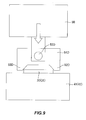
Fig. 5 illustrates a punch according to a first working example used in a magnet fracture apparatus. -
Fig. 6 illustrates a punch according to a second working example used in a magnet fracture apparatus. -
Fig. 7 illustrates a punch according to a third working example used in a magnet fracture apparatus. -
Fig. 8 illustrates a punch according to a fourth working example used in a magnet fracture apparatus. -
Fig. 9 illustrates a punch according to a fifth working example used in a magnet fracture apparatus. -
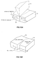
Fig. 10A illustrates actions of forces generated when a punch has partially hit a magnet. -
Fig. 10B shows an example of fracture of a magnet when a punch has partially hit the magnet. - First, a description is given of field-pole magnet according to the present invention as arranged in a rotor core of a rotary electric machine.
-
Fig. 1 is a schematic diagram showing configurations of major components of a permanent magnet type electric motor that utilizes magnets manufactured by a field-pole magnet manufacturing apparatus according to the present invention. More specifically,Fig. 1 shows a cross-sectional view and a side view of the permanent magnet type electric motor on the left side and the right side, respectively. InFig. 1 , a permanent magnet-embedded rotary electric machine AA (hereinafter simply referred to as "rotary electric machine") includes astator 10 having a shape of a circular ring and arotor 20 having a shape of a circular cylinder. Thestator 10 constitutes a part of a casing, which is not shown in the drawings. Therotor 20 is arranged coaxially with thisstator 10. - The
stator 10 includes astator core 11 and a plurality ofcoils 12. The plurality ofcoils 12 are housed inslots 13 that are formed in thestator core 11 at an equal angular interval on the same circumference around an axial center O, which is the origin. - The
rotor 20 includes arotor core 21, arotary shaft 23 that rotates integrally with therotor core 21, and a plurality of field-pole magnets 80. The plurality of field-pole magnets 80 are housed inslots 22 that are formed at an equal angular interval on the same circumference around the axial center O, which is the origin. - As shown in
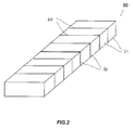
Fig. 2 , each of the field-pole magnets 80 housed in theslots 22 of therotor 20 is configured as an aggregate of a plurality of alignedmagnet pieces 31. The plurality ofmagnet pieces 31 are obtained by fracturing amagnet 30, which is rectangular in a plan view along the thickness direction, into smaller pieces along the width direction. The fracture surfaces of themagnet pieces 31 are bonded with one another usingresin 32. Theresin 32 used herein has, for example, a heat resistance up to approximately 200 °C, and provides electric insulation betweenadjacent magnet pieces 31. Therefore, overcurrent caused by a fluctuation in an active magnetic field is reduced by keeping the overcurrent within eachmagnet piece 31. As a result, heating of the field-pole magnets 80 associated with the overcurrent is suppressed, and irreversible thermal demagnetization is prevented. - In order to fracture the
magnet 30 into the plurality ofmagnet pieces 31, it is beneficial to formcutout grooves 33 in advance at sites of themagnet 30 to be fractured. Although the following describes themagnet 30 on which thecutout grooves 33 are formed, thesecutout grooves 33 are not indispensable. For example, if themagnet 30 can be fractured without forming thecutout grooves 33, thecutout grooves 33 may not be formed on themagnet 30. The greater the depth of the formedcutout grooves 33 from the front surface and the sharper the distal ends of thecutout grooves 33, the flatter the fracture surfaces of the fracturedmagnet pieces 31. - The
cutout grooves 33 may be formed by way of: a formation process for themagnet 30 via groove-forming projections provided in a die used to form themagnet 30; machining using a dicer, a slicer, and the like; laser beam emission; and wire-cut electrical discharge machining. - Incidentally, the
magnet 30 may be provided with the front surface thereof inclined in the width direction, or one side thereof in the width direction protruding compared to the other side thereof, due to poor parallelism of the raw material of themagnet 30 itself, warpage of the raw material, poor flatness of the raw material (concavities and convexities on the front surface of the raw material), and the like. If a punch is pressed against such amagnet 30 so as to fracture themagnet 30, partial hitting may occur whereby the punch hits one side of themagnet 30 in the width direction (the distribution of stress applied by the punch to themagnet 30 is uneven between one side and the other side bordered by the center of themagnet 30 in the width direction). This may cause the occurrence of abnormal fracture in which fracture surfaces do not match the intended fracture surfaces or become two-pronged. Consequently, the accuracy of the fracture surfaces may deteriorate. - In view of the above, the present invention provides an apparatus and a method for manufacturing a field-pole magnet that are provided with a punch suitable for improving the partial hitting against the
magnet 30. -
Figs. 3 and4 are schematic configuration diagrams showingmagnet fracture apparatuses 40 each representing a field-pole magnet manufacturing apparatus according to an embodiment of the present invention. The following describes an overview of themagnet fracture apparatuses 40 shown inFigs. 3 and4 , and configurations of punches that can be used in both of themagnet fracture apparatuses 40 shown inFigs. 3 and4 , in stated order. - In the
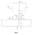
magnet fracture apparatus 40 shown inFig. 3 , themagnet 30 is fixed across a pair ofdies 41, and themagnet 30 is fractured in the form of three-point bending by lowering apunch 51 from above toward a portion of themagnet 30 located between the pair ofdies 41. Thismagnet fracture apparatus 40 includes the pair ofdies 41, which serves as a lower tool, andmagnet fixing jigs 43. Themagnet 30 is placed across the pair ofdies 41 and fixed by themagnet fixing jigs 43 at adjacent end portions of the pair ofdies 41. Themagnet fracture apparatus 40 also includes thepunch 51 that is provided in anupper tool 50 to fracture themagnet 30 by pushing the portion of themagnet 30 located between the pair of dies 41. - The
magnet fixing jigs 43 fix themagnet 30 by pressing themagnet 30 against edges of the pair of dies 41. More specifically, themagnet fixing jigs 43 press themagnet 30 by fastening bolts, by hydraulic pressure, or by air pressure. Thepunch 51 breaks themagnet 30 alongcutout grooves 32 of themagnet 30 by pressing down the portion of themagnet 30 located between the pair of dies 41. Thepunch 51 is driven by a servo press, a mechanical press, a hydraulic press, and the like. - In the
magnet fracture apparatus 40 configured in the above-described manner, themagnet 30 provided with thegrooves 32 is placed across the upper surfaces of the pair of dies 41. Here, themagnet 30 is placed on the pair of dies 41 such that the positions thereof desired to be fractured, that is to say, thecutout grooves 32 provided in advance at the intended fracture surfaces, oppose the dies 41. Themagnet 30 is fixed by themagnet fixing jigs 43 in the state where one of thecutout grooves 32 provided at the intended fracture surfaces is positioned at the center of the portion of themagnet 30 located between the pair of dies 41 using, for example, a servo mechanism. By lowering thepunch 51, themagnet 30 is broken into pieces along the stated one of thecutout grooves 32. Thereafter, the fixture by themagnet fixing jigs 43 is released, and themagnet 30 is conveyed by the length of one magnet piece 31 (corresponding to the distance between adjacent cutout grooves 32). By repeating the above operation, themagnet 30 is fractured into a plurality ofmagnet pieces 31. - In the
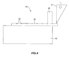
magnet fracture apparatus 40 shown inFig. 4 , themagnet 30 is fixed in the state where it protrudes from an end portion of a die 42, and themagnet 30 acting as a cantilever is fractured by lowering thepunch 51 from above toward a protruding portion of themagnet 30. - This
magnet fracture apparatus 40 includes the die 42, amagnet fixing jig 44, and thepunch 51. Themagnet 30 is placed on thedie 42. Themagnet fixing jig 44 fixes themagnet 30 at the end portion of thedie 42. Thepunch 51 fractures themagnet 30 by pushing the portion of themagnet 30 protruding from thedie 42. - The
magnet fixing jig 44 fixes themagnet 30 by pressing themagnet 30 against thedie 42. More specifically, themagnet fixing jig 44 presses themagnet 30 by fastening bolts or by hydraulic pressure. Thepunch 51 fractures themagnet 30 along thecutout grooves 32 of themagnet 30 by pressing down the portion of themagnet 30 protruding from thedie 42. Thepunch 51 is driven by a servo press, a mechanical press, a hydraulic press, and the like, for example. - In the
magnet dividing tool 40 configured in the above-described manner, themagnet 30 provided with thecutout grooves 32 is placed on the upper surface of thedie 42. Here, themagnet 30 is placed on the die 42 such that the positions thereof desired to be fractured, that is to say, thecutout grooves 32 provided in advance at the intended fracture surfaces, face upward or the direction away from thedie 42. Themagnet 30 is fixed by themagnet fixing jig 44 in the state where themagnet 30 is positioned so as to protrude from the right end of the die 42 by the length corresponding to one magnet piece 31 (corresponding to the distance between adjacent cutout grooves 32) using, for example, a servo mechanism. By lowering thepunch 51, themagnet 30 is fractured into pieces along one of thecutout grooves 32. By repeating the above operation, themagnet 30 is fractured into the plurality ofmagnet pieces 31. - The
punch 51 according to the present embodiment, which is used in the above-describedmagnet fracture apparatuses 40 shown inFigs. 3 and4 , has at least oneprojection 52 formed symmetrically with respect to the center of themagnet 30 in the width direction as shown inFigs. 5 to 9 . - A
punch 51 according to a first working example shown inFig. 5 has oneprojection 52 located at the center in the width direction of themagnet 30. It should be noted that the height of theprojection 52 is exaggerated in the illustration ofFig. 5 . In practice, the height of theprojection 52 is set to be equal to or larger than the size tolerance set with respect to parallelism of the raw material of themagnet 30, warpage of the raw material, and flatness of the material (concavities and convexities on the front surface of the raw material). By thus setting the height of theprojection 52 of thepunch 51, theprojection 52 can come into contact with the central position of themagnet 30 in the width direction, even in consideration of tolerances of parallelism of the raw material of themagnet 30, warpage of the raw material, and flatness of the material (concavities and convexities on the front surface of the raw material). - Incidentally, as shown in
Figs. 10A and 10B , when partial hitting has occurred whereby thepunch 51 comes into contact only with one side of themagnet 30 in the width direction (when the distribution of stress applied to themagnet 30 is uneven between one side and the other side bordered by the center of themagnet 30 in the width direction), a crack is formed only from one side of themagnet 30 in the width direction. As shown inFig. 10A , forces of tension and inertia are applied to themagnet 30. The force of tension acts on one side of themagnet 30 in the width direction so as to break open themagnet 30 in the left-right direction. The force of inertia apparently acts in the directions cancelling out the force of tension due to the mass of themagnet 30. The force of inertia due to the mass of themagnet 30 acts differently on the left side and the right side of the intended fracture surfaces. More specifically, the force of inertial is large on a long side that has a large size in the longitudinal direction and has a large mass, and is small on a short side (magnet piece 31) that has a small size in the longitudinal direction and has a small mass. - For this reason, as shown in
Fig. 10B , the net force obtained by adding the aforementioned forces of tension and inertia is not balanced between the long side and the short side, and broken surfaces warp toward the short side that is fractured off themagnet 30. In this case, abnormal fracture occurs in which fracture surfaces of themagnet 30 do not match the intended fracture surfaces or become two-pronged, resulting in deterioration of the accuracy of fracture surfaces. - On the other hand, according to the present working example, the
projection 52 provided in thepunch 51 can prevent the occurrence of partial hitting by reliability coming into contact with the central portion of themagnet 30 in the width direction at the time of fracturing themagnet 30. This allows cracks to be formed from the central position of themagnet 30 in the width direction during contact. The cracks formed in the central portion propagate toward both sides in the width direction of themagnet 30. When the cracks reach both side portions of themagnet 30, themagnet 30 is fractured along the intended fracture surfaces. Furthermore, as the origin of the formed cracks is the central portion of themagnet 30 in the width direction, the formed cracks reach the corresponding side portions substantially at the same time. - Moreover, the
projection 52 provided in thepunch 51 can reliably come into contact with the central portion of themagnet 30 in the width direction even under the presence of poor parallelism between upper and lower tools, poor parallelism of the raw material of themagnet 30 itself, warpage of the raw material, poor flatness of the material (concavities and convexities on the front surface of the raw material), and the like. This allows cracks to be formed from the central position of themagnet 30 in the width direction during contact. Hence, the cracks formed in the central portion propagate toward both sides in the width direction of themagnet 30. When the cracks reach both side portions of themagnet 30, themagnet 30 can be fractured along the intended fracture surfaces. As a result, the occurrence of abnormal fracture, in which fracture surfaces do not match the intended fracture surfaces or become two-pronged, can be prevented, and the accuracy of fracture surfaces can be improved. In addition, as increased accuracy of parallelism between upper and lower tools is not required, manufacture and management of the tools are easy. -
Fractured magnet pieces 31 are bonded in order of fracture by applying an adhesive agent between fracture surfaces. As a result, the fracturedmagnet pieces 31 are re-integrated as a field-pole magnet 80. An epoxy-based thermosetting adhesive agent, a UV curing adhesive agent, a two-component room temperature curing adhesive agent, and the like may be used as the adhesive agent. Furthermore, in order to ensure clearance betweenmagnet pieces 31, the adhesive agent contains spacer material such as glass beads, resin beads, and insulating cloths. Moreover, jigs are used when bonding themagnet pieces 31 by applying the adhesive agent. These jigs align themagnet pieces 31 by pressing themagnet pieces 31 in three directions, i.e. the alignment direction, the thickness direction and the width direction (or at least in two directions, i.e. the alignment direction and the thickness direction) by using a pressing force created by springs, hydraulic pressure, air pressure, and the like. - A
punch 51A according to a second working example shown inFig. 6 has aprojection 52A that projects in an arc-like fashion toward the central portion of themagnet 30 in the width direction. It should be noted that the height of theprojection 52A is exaggerated in the illustration ofFig. 6 . In practice, the height of theprojection 52A is set to be equal to or larger than the size tolerance set with respect to parallelism of the raw material of themagnet 30, warpage of the raw material, and flatness of the material (concavities and convexities on the front surface of the raw material). By thus setting the height of the arc-like projection 52A of thepunch 51A, theprojection 52A strongly comes into contact with the central position of themagnet 30 in the width direction, even in consideration of tolerances of parallelism of the raw material of themagnet 30, warpage of the raw material, and flatness of the material (concavities and convexities on the front surface of the raw material). Furthermore, the intensity of contact gradually decreases toward both sides in the width direction. - Therefore, in the present working example also, at the time of fracturing the
magnet 30, the ark-like projection 52A provided in thepunch 51A strongly comes into contact with the central portion of themagnet 30 in the width direction without causing partial hitting. Also, the intensity of contact gradually decreases toward both sides in the width direction. This allows cracks to be formed reliably from the central position of themagnet 30 in the width direction. The cracks formed in the central portion propagate toward both sides in the width direction of themagnet 30. When the cracks reach both side portions of themagnet 30, themagnet 30 can be fractured along the intended fracture surfaces. As a result, the occurrence of abnormal fracture, in which fracture surfaces do not match the intended fracture surfaces or become two-pronged, can be prevented, and the accuracy of fracture surfaces can be improved. - A
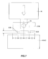
punch 51B according to a third working example shown inFig. 7 hasprojections 52B projecting from two areas in the width direction of themagnet 30. The twoprojections 52B are provided at the central positions of sections obtained by bisecting the width of themagnet 30, that is to say, at the positions corresponding to 1/4 and 3/4 of the width of themagnet 30. Therefore, the twoprojections 52B are formed symmetrically with respect to the center of themagnet 30 in the width direction. - It should be noted that the height of the
projections 52B is exaggerated in the illustration ofFig. 7 . In practice, the height of theprojections 52B is set to be equal to or larger than the size tolerance set with respect to parallelism of the raw material of themagnet 30, warpage of the raw material, and flatness of the material (concavities and convexities on the front surface of the raw material). Furthermore, thispunch 51B is joined to theupper tool 50 at the midpoint between the twoprojections 52B via asupport shaft 53, which is arranged to extend along the sideways direction perpendicular to the width direction of themagnet 30. Joining thepunch 51B to theupper tool 50 via thesupport shaft 53 in the above manner makes thepunch 51B swingable around thesupport shaft 53, and allows both of the twoprojections 52B to evenly come into contact with the front surface of themagnet 30 at the time of fracture. - In the present working example, at the time of fracturing the
magnet 30, thesupport shaft 53 allows the twoprojections 52B provided in thepunch 51B to swing in accordance with the condition of the front surface of themagnet 30. In this way, partial hitting can be prevented, and the twoprojections 52B can evenly and strongly come into contact with two areas of themagnet 30 corresponding to 1/4 and 3/4 of the width of themagnet 30. This allows cracks to be form reliably from the central positions of sections obtained by bisecting the width of themagnet 30. The formed cracks propagate toward both sides in the width direction of themagnet 30. Cracks propagating toward the center of themagnet 30 in the width direction merge at the central portion of themagnet 30 in the width direction. Cracks propagating toward both side portions of themagnet 30 in the width direction reach the corresponding side portions. Therefore, the timing at which the cracks merge at the central portion coincides with the timing at which the cracks reach the both side portions. At this timing, themagnet 30 can be fractured along the intended fracture surfaces. As a result, the occurrence of abnormal fracture, in which fracture surfaces do not match the intended fracture surfaces or become two-pronged, can be prevented, and the accuracy of fracture surfaces can be improved. - A punch according to a fourth working example shown in
Fig. 8 hasprojections 52C projecting from four areas in the width direction of themagnet 30. The fourprojections 52C are provided at the central positions of sections obtained by quadrisecting the width of themagnet 30. Therefore, the fourprojections 52C are formed symmetrically with respect to the center of themagnet 30 in the width direction. - It should be noted that the height of the
projections 52C is exaggerated in the illustration ofFig. 8 . In practice, the height of theprojections 52C is set to be equal to or larger than the size tolerance set with respect to parallelism of the raw material of themagnet 30, warpage of the raw material, and flatness of the material (concavities and convexities on the front surface of the raw material). - This
punch 51C is made up of two punch pieces 51C1, 51 C2, which are respectively located on one side and the other side in the width direction of themagnet 30. Each of the punch pieces 51C1, 51C2 has twoprojections 52C projecting toward themagnet 30 at both ends thereof. Each of the punch pieces 51C1, 51 C2 is joined to apunch support member 54 at the midpoint between the twoprojections 52C thereof via a support shaft 53C1, which is arranged to extend along the sideways direction perpendicular to the width direction of themagnet 30. Furthermore, thispunch support member 54 is joined to theupper tool 50 at the midpoint between the support shafts 53C1 supporting the punches 51C1, 51 C2 via a support shaft 53C2, which is arranged to extend along the sideways direction perpendicular to the width direction of themagnet 30. - Joining the punches 51C1, 51 C2 to the
punch support member 54 via the support shafts 53C1 in the above manner makes the punches 51C1, 51 C2 swingable around the support shafts 53C 1. Furthermore, joining thepunch support member 54 to theupper tool 50 via the support shaft 53C2 makes the punches 51C1, 51C2 swingable around the support shafts 53C1, 53C2. In this way, at the time of fracture, each of the two punches 51C1, 51C2 moves up and down in accordance with the shape of the front surface of one side of themagnet 30 in the width direction, thereby allowing both of the twoprojections 52C thereof to evenly come into contact with the surface of themagnet 30. - In the present working example, at the time of fracturing the
magnet 30, the support shafts 53C1, 53C2 allow the twoprojections 52C provided in each of the two punches 51C1, 51C2 to swing in accordance with the condition of the front surface of themagnet 30. In this way, partial hitting can be prevented, and theprojections 52C can evenly and strongly come into contact with the central positions of sections obtained by quadrisecting the width of themagnet 30. This allows cracks to be formed reliably from the central positions of sections obtained by quadrisecting the width of themagnet 30. The formed cracks propagate toward both sides in the width direction of themagnet 30. Cracks propagating in the width direction of themagnet 30 merge with other cracks that have been formed byadjacent projections 52C and are propagating in the width direction. Cracks propagating toward both side portions of themagnet 30 in the width direction reach the corresponding side portions. - The timing at which the cracks merge with one another coincides with the timing at which the cracks reach the both side portions. At this timing, the
magnet 30 can be fractured along the intended fracture surfaces. As a result, the occurrence of abnormal fracture, in which fracture surfaces do not match the intended fracture surfaces or become two-pronged, can be prevented, and the accuracy of fracture surfaces can be improved. - A
punch 51D according to a fifth embodiment shown inFig. 9 is used in the case where the width of themagnet 30 is relatively small. Thepunch 51D has twoprojections 52D that come into contact with both side edges of themagnet 30 in the width direction. That is to say, the twoprojections 52D are formed symmetrically with respect to the center of themagnet 30 in the width direction. The twoprojections 52D, which come into contact with both side edges of themagnet 30 in the width direction, project from both ends of thepunch 51D toward both sides of themagnet 30 in the width direction. The opposing inner edges of the twoprojections 52D are inclined to have a "flared" shape, such that the distance therebetween decreases toward the upward direction and increases toward the downward direction. Furthermore, thispunch 51D is joined to theupper tool 50 at the midpoint between the twoprojections 52D via asupport shaft 53D, which is arranged to extend along the sideways direction perpendicular to the width direction of themagnet 30. Joining thepunch 51D to theupper tool 50 via thesupport shaft 53D in the above manner makes thepunch 51 D swingable around thesupport shaft 53D. Therefore, at the time of fracture, thepunch 51D can evenly come into contact with both side edges of themagnet 30 in the width direction. - In the present working example, at the time of fracturing the
magnet 30, thesupport shaft 53D allows the twoprojections 52D provided in thepunch 51 D to swing in accordance with both side edges of themagnet 30 in the width direction. In this way, partial hitting can be prevented, and the twoprojections 52D can evenly come into contact with both side edges of themagnet 30 in the width direction. This allows cracks to be formed reliably from both side edges of themagnet 30 in the width direction. The formed cracks propagate toward the center of themagnet 30 in the width direction. Cracks propagating toward the center of themagnet 30 in the width direction merge at the central portion. When they merge, themagnet 30 can be fractured along the intended fracture surfaces. As a result, the occurrence of abnormal fracture, in which fracture surfaces do not match the intended fracture surfaces or become two-pronged, can be prevented, and the accuracy of fracture surfaces can be improved. The present embodiment can achieve the following effects. - (A) A field-pole magnet manufacturing apparatus fractures the
magnet 30 fixed on the dies 41, 42 serving as lower tools by causing thepunch 51 of theupper tool 50 to press themagnet 30 while in contact with themagnet 30. At least oneprojection 52 is formed in thepunch 51 of the upper tool symmetrically with respect to the central position of themagnet 30 in the width direction. In this way, at least oneprojection 52 of thepunch 51 comes into contact with themagnet 30 symmetrically with respect to the central position of themagnet 30 in the width direction. Consequently, partial hitting of thepunch 51 can be prevented. Therefore, the occurrence of abnormal fracture, in which fracture surfaces of themagnet pieces 31 do not match the intended fracture surfaces or become two-pronged, can be prevented even under the presence of poor parallelism of the raw material of themagnet 30, warpage of the raw material, poor flatness of the material (concavities and convexities on the front surface of the raw material), and the like. As a result, the accuracy of fracture surfaces of themagnet pieces 31 can be improved. In addition, as increased accuracy of parallelism between upper and lower tools is not required, manufacture and management of the tools are easy. - (B) The
punch 51B shown inFig. 7 has twoprojections 52B that are symmetric with respect to the central position of themagnet 30 in the width direction, and is supported swingably with respect to the upper tool around the midpoint between the twoprojections 52B. Therefore, at the time of fracturing themagnet 30, the twoprojections 52B provided in thepunch 51B prevents partial hitting by swinging in accordance with the condition of the front surface of themagnet 30, even under the presence of poor parallelism of the raw material of themagnet 30, warpage of the raw material, poor flatness of the material (concavities and convexities on the front surface of the raw material), and the like. As a result, the effect described in the above (A) is improved. - (C) The two
projections 52B shown inFig. 7 are arranged at the central positions of sections obtained by bisecting the width of themagnet 30. This allows cracks to be formed reliably from the central portions of sections obtained by bisecting the width of themagnet 30. The formed cracks propagate toward both sides in the width direction of themagnet 30 and merge at the central portion of themagnet 30 in the width direction. Cracks propagating toward both side portions of themagnet 30 in the width direction reach the corresponding side portions. In this way, the timing at which the cracks merge at the center coincides with the timing at which the cracks reach the both side portions. Furthermore, the occurrence of abnormal fracture, in which fracture surfaces do not match the intended fracture surfaces or become two-pronged, can be prevented, and the accuracy of fracture surfaces can be improved. - (D) The
punch 51C shown inFig. 8 is made up of thepunch support member 54 and the pair of punches 51C1, 51 C2. Thepunch support member 54 is swingable with respect to theupper tool 50 around the central position in the width direction of themagnet 30. The pair of punches 51C1, 51 C2 is swingable with respect to thepunch support member 54 about the central positions of sections obtained by bisecting the width of themagnet 30. Theprojections 52C are arranged at the central positions of sections obtained by quadrisecting the width of themagnet 30. Each of the pair of punches 51C1, 51 C2 is provided with twoprojections 52C. That is to say, theprojections 52C are provided symmetrically with respect to the central position of themagnet 30 in the width direction. Therefore, at the time of fracturing themagnet 30, the support shafts 53C1, 53C2 allow the twoprojections 52C provided in each of the two punches 51C1, 51 C2 to swing in accordance with the condition of the front surface of themagnet 30. In this way, partial hitting can be prevented, and theprojections 52C can evenly and strongly come into contact with the central positions of sections obtained by quadrisecting the width of themagnet 30. Cracks can be formed reliably from the central positions of sections obtained by quadrisecting the width of themagnet 30. The formed cracks propagate toward both sides in the width direction of themagnet 30. Cracks propagating in the width direction of themagnet 30 merge with other cracks that have been formed byadjacent projections 52C and are propagating in the width direction. Cracks propagating toward both side portions of themagnet 30 in the width direction reach the corresponding side portions. The timing at which the cracks merge with one another coincides with the timing at which the cracks reach the both side portions. At this timing, themagnet 30 can be fractured along the intended fracture surfaces. As a result, the occurrence of abnormal fracture, in which fracture surfaces do not match the intended fracture surfaces or become two-pronged, can be prevented, and the accuracy of fracture surfaces can be improved. - (E) The height of the
projections 52 is equal to or larger than the tolerance set with respect to parallelism of the raw material of themagnet 30, warpage of the raw material, and flatness of the front surface of the material determined by concavities and convexities. Therefore, theprojections 52 can reliably come into contact with the front surface of themagnet 30 even under the presence of poor parallelism of the raw material of themagnet 30, warpage of the raw material, poor flatness of the material (concavities and convexities on the front surface of the raw material), and the like. - This application claims priority based on
JP2011-209235
Claims (7)
- A field-pole magnet manufacturing apparatus configured to fracture a magnet fixed on a die serving as a lower tool by causing a punch of an upper tool to press the magnet while in contact with the magnet, wherein
the punch of the upper tool has at least one projection that is symmetric with respect to a central position of the magnet in a width direction of the magnet. - The field-pole magnet manufacturing apparatus according to claim 1, wherein
the punch has two projections that are symmetric with respect to the central position of the magnet in the width direction, and is supported swingably with respect to the upper tool around a midpoint between the two projections. - The field-pole magnet manufacturing apparatus according to claim 2, wherein
the two projections are arranged at central positions of sections obtained by bisecting a width of the magnet. - The field-pole magnet manufacturing apparatus according to claim 1, wherein
the punch has a punch support member and a pair of punches, the punch support member being swingable with respect to the upper tool around a central position in the width direction of the magnet, and the pair of punches being swingable with respect to the punch support member around central positions of sections obtained by bisecting a width of the magnet, and
as the at least one projection, two projections are provided in each of the pair of punches, each projection being arranged at central positions of sections obtained by quadrisecting the width of the magnet. - The field-pole magnet manufacturing apparatus according to any one of claims 1 to 4, wherein
a height of the projection is equal to or larger than a tolerance set with respect to parallelism of a raw material of the magnet, warpage of the raw material, and flatness of a front surface of the material determined by concavities and convexities. - A field-pole magnet manufacturing method for fracturing a magnet fixed on a die serving as a lower tool by causing a punch of an upper tool to press the magnet while in contact with the magnet, the method comprising:providing the punch of the upper tool with at least one projection that is symmetric with respect to a central position of the magnet in a width direction of the magnet;causing the projection of the punch to come into contact with an upper surface of the magnet at central positions of sections obtained by dividing a width of the magnet by a number of the projection of the punch;pressing the punch against the magnet so as to form cracks at sites of the magnet that are in contact with the punch; andfracturing the magnet by propagation of the formed cracks in the width direction.
- The field-pole magnet manufacturing method according to claim 6, wherein
the punch, which is provided with the at least one projection that is symmetric with respect to the central position of the magnet in the width direction, is supported swingably with respect to the upper tool around a midpoint between projections located at both ends.
Applications Claiming Priority (2)
| Application Number | Priority Date | Filing Date | Title |
|---|---|---|---|
| JP2011209235A JP6393019B2 (en) | 2011-09-26 | 2011-09-26 | Field pole magnet body manufacturing apparatus and method |
| PCT/JP2012/073977 WO2013047298A1 (en) | 2011-09-26 | 2012-09-20 | Manufacturing device for magnet body for field pole and manufacturing method for same |
Publications (3)
| Publication Number | Publication Date |
|---|---|
| EP2763294A1 true EP2763294A1 (en) | 2014-08-06 |
| EP2763294A4 EP2763294A4 (en) | 2016-05-04 |
| EP2763294B1 EP2763294B1 (en) | 2018-08-15 |
Family
ID=47995330
Family Applications (1)
| Application Number | Title | Priority Date | Filing Date |
|---|---|---|---|
| EP12837243.0A Active EP2763294B1 (en) | 2011-09-26 | 2012-09-20 | Apparatus and method for manufacturing field-pole magnet |
Country Status (8)
| Country | Link |
|---|---|
| US (1) | US10583579B2 (en) |
| EP (1) | EP2763294B1 (en) |
| JP (1) | JP6393019B2 (en) |
| KR (1) | KR101560993B1 (en) |
| CN (1) | CN103718436B (en) |
| AU (1) | AU2012317856B2 (en) |
| CA (1) | CA2848315C (en) |
| WO (1) | WO2013047298A1 (en) |
Families Citing this family (14)
| Publication number | Priority date | Publication date | Assignee | Title |
|---|---|---|---|---|
| WO2013115224A1 (en) * | 2012-02-01 | 2013-08-08 | 日産自動車株式会社 | Method for manufacturing magnet pieces for forming field-pole magnets |
| US10668641B2 (en) * | 2013-06-13 | 2020-06-02 | Nissan Motor Co., Ltd. | Magnet cutting device |
| JP6079887B2 (en) * | 2013-08-29 | 2017-02-15 | 日産自動車株式会社 | Cleaving method and cleaving apparatus for manufacturing a magnet piece constituting a field pole magnet body disposed in a rotating electrical machine |
| EP3057207B1 (en) | 2013-10-09 | 2018-10-10 | Nissan Motor Co., Ltd | Method and device for manufacturing magnet pieces configuring a field pole magnet to be arranged in a rotary machine |
| CN103659231A (en) * | 2013-12-31 | 2014-03-26 | 泰信电机(苏州)有限公司 | Installing and reinforcing device for rotor iron core and revolving shaft |
| JP6146702B2 (en) * | 2014-08-28 | 2017-06-14 | 株式会社安川電機 | Magnet, laminated magnet, laminated magnet manufacturing method, laminated magnet manufacturing system |
| EP3073612B1 (en) * | 2015-03-26 | 2019-10-09 | Skf Magnetic Mechatronics | Stator assembly and magnetic bearing or electric motor comprising such a stator assembly |
| JP6542835B2 (en) * | 2017-05-30 | 2019-07-10 | ファナック株式会社 | Stator and rotating electric machine |
| CN109038968B (en) * | 2018-08-20 | 2020-05-19 | 宁波菲仕技术股份有限公司 | Method for manufacturing magnetic steel fixing plate of linear motor |
| JP6830996B1 (en) * | 2019-12-26 | 2021-02-17 | 山洋電気株式会社 | Frame structure of synchronous motor and manufacturing method of frame and armature |
| CN211981596U (en) * | 2020-04-07 | 2020-11-20 | 精进电动科技股份有限公司 | A rotary stator positioning tablet and positioning structure |
| KR20220040265A (en) * | 2020-09-23 | 2022-03-30 | 현대모비스 주식회사 | Motor |
| JP7163948B2 (en) * | 2020-10-30 | 2022-11-01 | 株式会社富士通ゼネラル | compressor |
| CN220210077U (en) * | 2023-01-31 | 2023-12-19 | 日本电产株式会社 | Motor and electric product |
Family Cites Families (18)
| Publication number | Priority date | Publication date | Assignee | Title |
|---|---|---|---|---|
| US3882807A (en) * | 1974-04-08 | 1975-05-13 | Texas Instruments Inc | Method of separating dual inline packages from a strip |
| JPH0195831A (en) * | 1987-10-07 | 1989-04-13 | Nikka Eng Kk | Center punching device |
| AT391858B (en) * | 1988-04-25 | 1990-12-10 | Lisec Peter | DEVICE FOR BREAKING SINGLE-SIDED GLASS PANELS |
| DE9116425U1 (en) * | 1991-07-19 | 1992-10-08 | Karl Marbach Gmbh & Co, 7100 Heilbronn | Device for removing stripped parts, such as waste pieces, from a sheet of material containing blanks or the like |
| JP2000006130A (en) | 1998-06-24 | 2000-01-11 | Kajishima Kogyo Kk | Dividing device for molded material for tile |
| JP2002018797A (en) * | 2000-06-29 | 2002-01-22 | Nisshinbo Ind Inc | Method and apparatus for cutting substrate made of brittle material |
| JP3741995B2 (en) * | 2001-10-31 | 2006-02-01 | 株式会社ルネサステクノロジ | Device and method for removing tie bar after resin sealing of semiconductor device, and method for manufacturing semiconductor device |
| JP2004026539A (en) * | 2002-06-24 | 2004-01-29 | Nakamura Tome Precision Ind Co Ltd | Method and apparatus for cutting glass substrate |
| JP4750427B2 (en) * | 2005-01-13 | 2011-08-17 | 株式会社ディスコ | Wafer laser processing method |
| US20070039990A1 (en) * | 2005-05-06 | 2007-02-22 | Kemmerer Marvin W | Impact induced crack propagation in a brittle material |
| DE102006049044B4 (en) * | 2006-10-18 | 2018-01-11 | Trumpf Werkzeugmaschinen Gmbh + Co. Kg | Tool for cutting plate-like workpieces |
| JP4497198B2 (en) | 2007-12-06 | 2010-07-07 | トヨタ自動車株式会社 | Permanent magnet and method for manufacturing the same, and rotor and IPM motor |
| CN102171908B (en) | 2008-10-02 | 2014-05-28 | 日产自动车株式会社 | Field pole magnet, field pole magnet manufacturing method, and permanent magnet rotary machine |
| JP2010159187A (en) * | 2009-01-09 | 2010-07-22 | Epson Imaging Devices Corp | Method and apparatus for breaking substrate, and breaking bar |
| JP5428482B2 (en) * | 2009-04-15 | 2014-02-26 | 日産自動車株式会社 | Method of manufacturing field pole magnet body and permanent magnet motor |
| AU2010266799B2 (en) * | 2009-06-29 | 2014-12-04 | Hapai Transfer Systems Limited | Person moving devices for moving persons of limited mobility |
| WO2011004490A1 (en) * | 2009-07-10 | 2011-01-13 | トヨタ自動車株式会社 | Device for cleaving magnet and method for cleaving magnet |
| JP5614096B2 (en) * | 2010-05-19 | 2014-10-29 | 日産自動車株式会社 | Permanent magnet embedded in rotor core of rotating electrical machine and method for manufacturing the same |
-
2011
- 2011-09-26 JP JP2011209235A patent/JP6393019B2/en active Active
-
2012
- 2012-09-20 AU AU2012317856A patent/AU2012317856B2/en not_active Ceased
- 2012-09-20 WO PCT/JP2012/073977 patent/WO2013047298A1/en not_active Ceased
- 2012-09-20 KR KR1020147005295A patent/KR101560993B1/en not_active Expired - Fee Related
- 2012-09-20 CA CA2848315A patent/CA2848315C/en active Active
- 2012-09-20 EP EP12837243.0A patent/EP2763294B1/en active Active
- 2012-09-20 US US14/347,040 patent/US10583579B2/en active Active
- 2012-09-20 CN CN201280038447.7A patent/CN103718436B/en active Active
Also Published As
| Publication number | Publication date |
|---|---|
| WO2013047298A1 (en) | 2013-04-04 |
| KR101560993B1 (en) | 2015-10-15 |
| EP2763294A4 (en) | 2016-05-04 |
| CN103718436B (en) | 2016-11-02 |
| CA2848315A1 (en) | 2013-04-04 |
| CN103718436A (en) | 2014-04-09 |
| JP2013070578A (en) | 2013-04-18 |
| KR20140042921A (en) | 2014-04-07 |
| AU2012317856B2 (en) | 2015-06-11 |
| US10583579B2 (en) | 2020-03-10 |
| EP2763294B1 (en) | 2018-08-15 |
| CA2848315C (en) | 2016-08-16 |
| JP6393019B2 (en) | 2018-09-19 |
| AU2012317856A1 (en) | 2014-02-20 |
| US20140231483A1 (en) | 2014-08-21 |
Similar Documents
| Publication | Publication Date | Title |
|---|---|---|
| CA2848315C (en) | Apparatus and method for manufacturing field-pole magnet | |
| EP2584681B1 (en) | Method for manufacturing permanent magnets for a dynamo-electric machine | |
| JP5446428B2 (en) | Permanent magnet for field pole, method for manufacturing the same, and permanent magnet type rotating electrical machine provided with permanent magnet for field pole | |
| US9251951B2 (en) | Method of manufacturing magnet segment of field pole magnet body | |
| JP5867052B2 (en) | Field pole magnet body manufacturing apparatus and method | |
| JP5994280B2 (en) | Manufacturing method and manufacturing apparatus of magnet piece constituting magnet body for field pole | |
| JP5906768B2 (en) | Magnet piece manufacturing apparatus constituting field pole magnet body and manufacturing method thereof | |
| JP5761383B2 (en) | Method for manufacturing field pole magnet body | |
| JP5867102B2 (en) | Field pole magnet body manufacturing apparatus and method | |
| JP2013066990A (en) | Device for manufacturing magnet body for magnetic field pole and its manufacturing method | |
| WO2013115301A1 (en) | Device for manufacturing magnet pieces for forming field-pole magnets |
Legal Events
| Date | Code | Title | Description |
|---|---|---|---|
| PUAI | Public reference made under article 153(3) epc to a published international application that has entered the european phase |
Free format text: ORIGINAL CODE: 0009012 |
|
| 17P | Request for examination filed |
Effective date: 20140415 |
|
| AK | Designated contracting states |
Kind code of ref document: A1 Designated state(s): AL AT BE BG CH CY CZ DE DK EE ES FI FR GB GR HR HU IE IS IT LI LT LU LV MC MK MT NL NO PL PT RO RS SE SI SK SM TR |
|
| DAX | Request for extension of the european patent (deleted) | ||
| RA4 | Supplementary search report drawn up and despatched (corrected) |
Effective date: 20160405 |
|
| RIC1 | Information provided on ipc code assigned before grant |
Ipc: B26F 3/00 20060101ALI20160330BHEP Ipc: H02K 1/27 20060101ALI20160330BHEP Ipc: H02K 15/03 20060101AFI20160330BHEP |
|
| 17Q | First examination report despatched |
Effective date: 20170526 |
|
| REG | Reference to a national code |
Ref country code: DE Ref legal event code: R079 Ref document number: 602012049910 Country of ref document: DE Free format text: PREVIOUS MAIN CLASS: H02K0015030000 Ipc: H01F0041020000 |
|
| GRAP | Despatch of communication of intention to grant a patent |
Free format text: ORIGINAL CODE: EPIDOSNIGR1 |
|
| RIC1 | Information provided on ipc code assigned before grant |
Ipc: H01F 41/02 20060101AFI20180302BHEP Ipc: H02K 15/03 20060101ALI20180302BHEP |
|
| INTG | Intention to grant announced |
Effective date: 20180409 |
|
| GRAS | Grant fee paid |
Free format text: ORIGINAL CODE: EPIDOSNIGR3 |
|
| GRAA | (expected) grant |
Free format text: ORIGINAL CODE: 0009210 |
|
| RIN1 | Information on inventor provided before grant (corrected) |
Inventor name: KOIKE, YASUHISA Inventor name: NISHIMURA, KIMIO Inventor name: TAKAICHI, KAZUHIRO Inventor name: ISHIGURO, KUNITOMO Inventor name: HASEGAWA, KIYOSHI Inventor name: TAKEUCHI, HIROHARU |
|
| AK | Designated contracting states |
Kind code of ref document: B1 Designated state(s): AL AT BE BG CH CY CZ DE DK EE ES FI FR GB GR HR HU IE IS IT LI LT LU LV MC MK MT NL NO PL PT RO RS SE SI SK SM TR |
|
| REG | Reference to a national code |
Ref country code: CH Ref legal event code: EP Ref country code: GB Ref legal event code: FG4D Ref country code: AT Ref legal event code: REF Ref document number: 1030702 Country of ref document: AT Kind code of ref document: T Effective date: 20180815 |
|
| REG | Reference to a national code |
Ref country code: IE Ref legal event code: FG4D |
|
| REG | Reference to a national code |
Ref country code: DE Ref legal event code: R096 Ref document number: 602012049910 Country of ref document: DE |
|
| REG | Reference to a national code |
Ref country code: FR Ref legal event code: PLFP Year of fee payment: 7 |
|
| REG | Reference to a national code |
Ref country code: NL Ref legal event code: MP Effective date: 20180815 |
|
| REG | Reference to a national code |
Ref country code: LT Ref legal event code: MG4D |
|
| REG | Reference to a national code |
Ref country code: AT Ref legal event code: MK05 Ref document number: 1030702 Country of ref document: AT Kind code of ref document: T Effective date: 20180815 |
|
| PG25 | Lapsed in a contracting state [announced via postgrant information from national office to epo] |
Ref country code: BG Free format text: LAPSE BECAUSE OF FAILURE TO SUBMIT A TRANSLATION OF THE DESCRIPTION OR TO PAY THE FEE WITHIN THE PRESCRIBED TIME-LIMIT Effective date: 20181115 Ref country code: NL Free format text: LAPSE BECAUSE OF FAILURE TO SUBMIT A TRANSLATION OF THE DESCRIPTION OR TO PAY THE FEE WITHIN THE PRESCRIBED TIME-LIMIT Effective date: 20180815 Ref country code: NO Free format text: LAPSE BECAUSE OF FAILURE TO SUBMIT A TRANSLATION OF THE DESCRIPTION OR TO PAY THE FEE WITHIN THE PRESCRIBED TIME-LIMIT Effective date: 20181115 Ref country code: GR Free format text: LAPSE BECAUSE OF FAILURE TO SUBMIT A TRANSLATION OF THE DESCRIPTION OR TO PAY THE FEE WITHIN THE PRESCRIBED TIME-LIMIT Effective date: 20181116 Ref country code: IS Free format text: LAPSE BECAUSE OF FAILURE TO SUBMIT A TRANSLATION OF THE DESCRIPTION OR TO PAY THE FEE WITHIN THE PRESCRIBED TIME-LIMIT Effective date: 20181215 Ref country code: AT Free format text: LAPSE BECAUSE OF FAILURE TO SUBMIT A TRANSLATION OF THE DESCRIPTION OR TO PAY THE FEE WITHIN THE PRESCRIBED TIME-LIMIT Effective date: 20180815 Ref country code: RS Free format text: LAPSE BECAUSE OF FAILURE TO SUBMIT A TRANSLATION OF THE DESCRIPTION OR TO PAY THE FEE WITHIN THE PRESCRIBED TIME-LIMIT Effective date: 20180815 Ref country code: LT Free format text: LAPSE BECAUSE OF FAILURE TO SUBMIT A TRANSLATION OF THE DESCRIPTION OR TO PAY THE FEE WITHIN THE PRESCRIBED TIME-LIMIT Effective date: 20180815 Ref country code: FI Free format text: LAPSE BECAUSE OF FAILURE TO SUBMIT A TRANSLATION OF THE DESCRIPTION OR TO PAY THE FEE WITHIN THE PRESCRIBED TIME-LIMIT Effective date: 20180815 Ref country code: SE Free format text: LAPSE BECAUSE OF FAILURE TO SUBMIT A TRANSLATION OF THE DESCRIPTION OR TO PAY THE FEE WITHIN THE PRESCRIBED TIME-LIMIT Effective date: 20180815 |
|
| PG25 | Lapsed in a contracting state [announced via postgrant information from national office to epo] |
Ref country code: AL Free format text: LAPSE BECAUSE OF FAILURE TO SUBMIT A TRANSLATION OF THE DESCRIPTION OR TO PAY THE FEE WITHIN THE PRESCRIBED TIME-LIMIT Effective date: 20180815 Ref country code: HR Free format text: LAPSE BECAUSE OF FAILURE TO SUBMIT A TRANSLATION OF THE DESCRIPTION OR TO PAY THE FEE WITHIN THE PRESCRIBED TIME-LIMIT Effective date: 20180815 Ref country code: LV Free format text: LAPSE BECAUSE OF FAILURE TO SUBMIT A TRANSLATION OF THE DESCRIPTION OR TO PAY THE FEE WITHIN THE PRESCRIBED TIME-LIMIT Effective date: 20180815 |
|
| PG25 | Lapsed in a contracting state [announced via postgrant information from national office to epo] |
Ref country code: PL Free format text: LAPSE BECAUSE OF FAILURE TO SUBMIT A TRANSLATION OF THE DESCRIPTION OR TO PAY THE FEE WITHIN THE PRESCRIBED TIME-LIMIT Effective date: 20180815 Ref country code: EE Free format text: LAPSE BECAUSE OF FAILURE TO SUBMIT A TRANSLATION OF THE DESCRIPTION OR TO PAY THE FEE WITHIN THE PRESCRIBED TIME-LIMIT Effective date: 20180815 Ref country code: CZ Free format text: LAPSE BECAUSE OF FAILURE TO SUBMIT A TRANSLATION OF THE DESCRIPTION OR TO PAY THE FEE WITHIN THE PRESCRIBED TIME-LIMIT Effective date: 20180815 Ref country code: IT Free format text: LAPSE BECAUSE OF FAILURE TO SUBMIT A TRANSLATION OF THE DESCRIPTION OR TO PAY THE FEE WITHIN THE PRESCRIBED TIME-LIMIT Effective date: 20180815 Ref country code: ES Free format text: LAPSE BECAUSE OF FAILURE TO SUBMIT A TRANSLATION OF THE DESCRIPTION OR TO PAY THE FEE WITHIN THE PRESCRIBED TIME-LIMIT Effective date: 20180815 Ref country code: RO Free format text: LAPSE BECAUSE OF FAILURE TO SUBMIT A TRANSLATION OF THE DESCRIPTION OR TO PAY THE FEE WITHIN THE PRESCRIBED TIME-LIMIT Effective date: 20180815 |
|
| REG | Reference to a national code |
Ref country code: CH Ref legal event code: PL |
|
| REG | Reference to a national code |
Ref country code: DE Ref legal event code: R097 Ref document number: 602012049910 Country of ref document: DE |
|
| PG25 | Lapsed in a contracting state [announced via postgrant information from national office to epo] |
Ref country code: DK Free format text: LAPSE BECAUSE OF FAILURE TO SUBMIT A TRANSLATION OF THE DESCRIPTION OR TO PAY THE FEE WITHIN THE PRESCRIBED TIME-LIMIT Effective date: 20180815 Ref country code: SM Free format text: LAPSE BECAUSE OF FAILURE TO SUBMIT A TRANSLATION OF THE DESCRIPTION OR TO PAY THE FEE WITHIN THE PRESCRIBED TIME-LIMIT Effective date: 20180815 Ref country code: SK Free format text: LAPSE BECAUSE OF FAILURE TO SUBMIT A TRANSLATION OF THE DESCRIPTION OR TO PAY THE FEE WITHIN THE PRESCRIBED TIME-LIMIT Effective date: 20180815 |
|
| REG | Reference to a national code |
Ref country code: BE Ref legal event code: MM Effective date: 20180930 |
|
| PLBE | No opposition filed within time limit |
Free format text: ORIGINAL CODE: 0009261 |
|
| STAA | Information on the status of an ep patent application or granted ep patent |
Free format text: STATUS: NO OPPOSITION FILED WITHIN TIME LIMIT |
|
| REG | Reference to a national code |
Ref country code: IE Ref legal event code: MM4A |
|
| PG25 | Lapsed in a contracting state [announced via postgrant information from national office to epo] |
Ref country code: MC Free format text: LAPSE BECAUSE OF FAILURE TO SUBMIT A TRANSLATION OF THE DESCRIPTION OR TO PAY THE FEE WITHIN THE PRESCRIBED TIME-LIMIT Effective date: 20180815 Ref country code: LU Free format text: LAPSE BECAUSE OF NON-PAYMENT OF DUE FEES Effective date: 20180920 |
|
| 26N | No opposition filed |
Effective date: 20190516 |
|
| PG25 | Lapsed in a contracting state [announced via postgrant information from national office to epo] |
Ref country code: IE Free format text: LAPSE BECAUSE OF NON-PAYMENT OF DUE FEES Effective date: 20180920 |
|
| PG25 | Lapsed in a contracting state [announced via postgrant information from national office to epo] |
Ref country code: SI Free format text: LAPSE BECAUSE OF FAILURE TO SUBMIT A TRANSLATION OF THE DESCRIPTION OR TO PAY THE FEE WITHIN THE PRESCRIBED TIME-LIMIT Effective date: 20180815 Ref country code: CH Free format text: LAPSE BECAUSE OF NON-PAYMENT OF DUE FEES Effective date: 20180930 Ref country code: LI Free format text: LAPSE BECAUSE OF NON-PAYMENT OF DUE FEES Effective date: 20180930 Ref country code: BE Free format text: LAPSE BECAUSE OF NON-PAYMENT OF DUE FEES Effective date: 20180930 |
|
| PG25 | Lapsed in a contracting state [announced via postgrant information from national office to epo] |
Ref country code: MT Free format text: LAPSE BECAUSE OF NON-PAYMENT OF DUE FEES Effective date: 20180920 |
|
| PG25 | Lapsed in a contracting state [announced via postgrant information from national office to epo] |
Ref country code: TR Free format text: LAPSE BECAUSE OF FAILURE TO SUBMIT A TRANSLATION OF THE DESCRIPTION OR TO PAY THE FEE WITHIN THE PRESCRIBED TIME-LIMIT Effective date: 20180815 |
|
| PG25 | Lapsed in a contracting state [announced via postgrant information from national office to epo] |
Ref country code: HU Free format text: LAPSE BECAUSE OF FAILURE TO SUBMIT A TRANSLATION OF THE DESCRIPTION OR TO PAY THE FEE WITHIN THE PRESCRIBED TIME-LIMIT; INVALID AB INITIO Effective date: 20120920 Ref country code: PT Free format text: LAPSE BECAUSE OF FAILURE TO SUBMIT A TRANSLATION OF THE DESCRIPTION OR TO PAY THE FEE WITHIN THE PRESCRIBED TIME-LIMIT Effective date: 20180815 |
|
| PG25 | Lapsed in a contracting state [announced via postgrant information from national office to epo] |
Ref country code: MK Free format text: LAPSE BECAUSE OF NON-PAYMENT OF DUE FEES Effective date: 20180815 Ref country code: CY Free format text: LAPSE BECAUSE OF FAILURE TO SUBMIT A TRANSLATION OF THE DESCRIPTION OR TO PAY THE FEE WITHIN THE PRESCRIBED TIME-LIMIT Effective date: 20180815 |
|
| PGFP | Annual fee paid to national office [announced via postgrant information from national office to epo] |
Ref country code: DE Payment date: 20250820 Year of fee payment: 14 |
|
| PGFP | Annual fee paid to national office [announced via postgrant information from national office to epo] |
Ref country code: GB Payment date: 20250820 Year of fee payment: 14 |
|
| PGFP | Annual fee paid to national office [announced via postgrant information from national office to epo] |
Ref country code: FR Payment date: 20250821 Year of fee payment: 14 |