EP2762771A2 - Lighting device for vehicle, radiating device and lighting device - Google Patents
Lighting device for vehicle, radiating device and lighting device Download PDFInfo
- Publication number
- EP2762771A2 EP2762771A2 EP14153233.3A EP14153233A EP2762771A2 EP 2762771 A2 EP2762771 A2 EP 2762771A2 EP 14153233 A EP14153233 A EP 14153233A EP 2762771 A2 EP2762771 A2 EP 2762771A2
- Authority
- EP
- European Patent Office
- Prior art keywords
- radiating
- module
- radiating device
- heat
- lighting device
- Prior art date
- Legal status (The legal status is an assumption and is not a legal conclusion. Google has not performed a legal analysis and makes no representation as to the accuracy of the status listed.)
- Granted
Links
Images





Classifications
-
- F—MECHANICAL ENGINEERING; LIGHTING; HEATING; WEAPONS; BLASTING
- F21—LIGHTING
- F21V—FUNCTIONAL FEATURES OR DETAILS OF LIGHTING DEVICES OR SYSTEMS THEREOF; STRUCTURAL COMBINATIONS OF LIGHTING DEVICES WITH OTHER ARTICLES, NOT OTHERWISE PROVIDED FOR
- F21V29/00—Protecting lighting devices from thermal damage; Cooling or heating arrangements specially adapted for lighting devices or systems
-
- F—MECHANICAL ENGINEERING; LIGHTING; HEATING; WEAPONS; BLASTING
- F21—LIGHTING
- F21S—NON-PORTABLE LIGHTING DEVICES; SYSTEMS THEREOF; VEHICLE LIGHTING DEVICES SPECIALLY ADAPTED FOR VEHICLE EXTERIORS
- F21S45/00—Arrangements within vehicle lighting devices specially adapted for vehicle exteriors, for purposes other than emission or distribution of light
- F21S45/60—Heating of lighting devices, e.g. for demisting
-
- F—MECHANICAL ENGINEERING; LIGHTING; HEATING; WEAPONS; BLASTING
- F21—LIGHTING
- F21S—NON-PORTABLE LIGHTING DEVICES; SYSTEMS THEREOF; VEHICLE LIGHTING DEVICES SPECIALLY ADAPTED FOR VEHICLE EXTERIORS
- F21S41/00—Illuminating devices specially adapted for vehicle exteriors, e.g. headlamps
-
- F—MECHANICAL ENGINEERING; LIGHTING; HEATING; WEAPONS; BLASTING
- F21—LIGHTING
- F21S—NON-PORTABLE LIGHTING DEVICES; SYSTEMS THEREOF; VEHICLE LIGHTING DEVICES SPECIALLY ADAPTED FOR VEHICLE EXTERIORS
- F21S45/00—Arrangements within vehicle lighting devices specially adapted for vehicle exteriors, for purposes other than emission or distribution of light
- F21S45/40—Cooling of lighting devices
- F21S45/47—Passive cooling, e.g. using fins, thermal conductive elements or openings
-
- F—MECHANICAL ENGINEERING; LIGHTING; HEATING; WEAPONS; BLASTING
- F21—LIGHTING
- F21S—NON-PORTABLE LIGHTING DEVICES; SYSTEMS THEREOF; VEHICLE LIGHTING DEVICES SPECIALLY ADAPTED FOR VEHICLE EXTERIORS
- F21S45/00—Arrangements within vehicle lighting devices specially adapted for vehicle exteriors, for purposes other than emission or distribution of light
- F21S45/40—Cooling of lighting devices
- F21S45/49—Attachment of the cooling means
-
- F—MECHANICAL ENGINEERING; LIGHTING; HEATING; WEAPONS; BLASTING
- F28—HEAT EXCHANGE IN GENERAL
- F28F—DETAILS OF HEAT-EXCHANGE AND HEAT-TRANSFER APPARATUS, OF GENERAL APPLICATION
- F28F3/00—Plate-like or laminated elements; Assemblies of plate-like or laminated elements
Definitions
- Embodiments of the present invention relate to a radiating device, a lighting device including the same, and a lighting device for a vehicle.
- a light emitting diode (LED) device is directed to converting an electrical signal to infrared rays or light using the properties of a compound semiconductor. Unlike a fluorescent lamp, the LED device does not use any harmful substances such as mercury, which results in less environment contamination, and has an advantage that its life span is longer as compared to a conventional light source. The LED device also consumes low electric power as compared to a conventional light source, and shows excellent visibility and low glariness thanks to a high color temperature. Thus, the LED device has been widely used as a light source of a head lamp for a vehicle.
- a head lamp for a vehicle shows a basic environmental temperature of approximately about 80°C due to the heat of an engine, and is vulnerable to the radiation of heat because it is sealed, so an increase in its internal temperature has an influence on the LED's life span. Accordingly, a radiating system with high performance capable of effectively emitting heat generated from the LED is needed, so a fan for emitting the heat generated from the LED is adopted.
- FIG. 1 is a view showing a conventional radiant heat structure for a vehicle headlamp.
- the conventional radiant heat structure for the vehicle headlamp includes: an LED module 20 formed in an inner side of a housing of the head lamp; a heat sink 30 formed at a bottom surface of the LED module 20; and a cooling fan 40 installed at a lower part of the heat sink 30.
- the conventional radiant heat structure for the vehicle head lamp enables the heat generated from the LED module to be emitted to the outside through the heat sink 30 formed at the bottom surface of the LED module 20, and has improved radiant heat efficiency by cooling the heat sink 30 with the cooling pan 40.
- the conventional radiating structure for the vehicle headlamp is problematic in that a cost and a weight of the vehicle are increased and space utilization is reduced because the separate cooling fan 40 is mounted, and a cooling property is reduced because hot windy is generated in a case where the cooling fan 40 is used for long hours.
- the lifespan of the cooling fan as well as the lifespan of the LED may become a problem, and there is also a problem that a separate electric motor is applied to the LED headlamp which pursues for low power.
- the LED hardly generates infrared rays or ultraviolet rays, so it is also problematic that freezing of the headlamp is caused due to the snow and the like.
- An aspect of embodiments of the present invention provides a radiating device and a lighting device that can reduce a production cost and a weight and can improve efficiency of space utilization by forming a second radiating module composed of different thermal conductive materials and removing a fan, and can also realize the effects of an optical member such as snow melting, defrosting, demisting and defogging by radiating heat to a light emitting space.
- An aspect of embodiments of the present invention also provides a radiating device and a lighting device that can increase a radiant heat property by integrally forming a first radiating module and a second radiating module through insert injection molding.
- a radiating device including: a first radiating module configured to receive heat generated from a light source module; and a second radiating module including a first member extending to the first heat dissipation module and transmitting the received heat, and a second member configured to form a light emitting space and to radiate the heat transmitted from the first member to the light emitting space.
- Embodiments of the present invention relate to a radiating device and a lighting device, and are intended to provide a structure of the radiating device and a structure of the lighting device that can remove a fan while improving a radiant heat effect by forming a second radiating module made of a thermal conductive resin and metal, and can realize the effects of an optical member such as the snow melting, defrosting, demisting and defogging.
- the radiating device and the lighting device according to the embodiments of the present invention can be applied to various lamp devices such as a lighting device for a vehicle, a lighting device for home use, an industrial lighting device for which illuminating is required.
- a lighting device for a vehicle a lighting device for home use
- an industrial lighting device for which illuminating is required when the radiating device and the lighting device are applied to a lamp for a vehicle, they can be also applied to a head light, a rear light and the like.
- the radiating device and the lighting device can be applied to all the lighting-related applications which have been already developed and then commercialized or which can be implemented according to the technology advances.
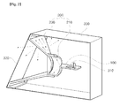
- FIG. 2 illustrates one embodiment for a structure of a lighting device including a radiating device according to an embodiment of the present invention.
- the radiating device may include: a first radiating module 100 configured to receive heat generated from a light source module 310; and a second radiating module 200 configured to receive the heat received in and transmitted from the first radiating module 100 and to radiate the heat to a light emitting space.
- the lighting device may include: an optical member 320 fixed to an end of the second radiating module 200 within a housing 330; and a light source module 310 mounted on the first radiating module 100 to emit light the optical member.
- the first radiating module 100 receives heat generated from the light source module 310 mounted in an upper part thereof.
- the first radiating module 100 may be made of a metal having high thermal conductivity, for example, Al, Cu, Ag, Cr, Ni and the like.
- a heat sink is not disposed at a lower part of the first radiating module 100, the present embodiment of the invention can realize an excellent radiant heat effect.
- the light source module 310 mounted in the upper part of the first radiating module includes a printed circuit board and a light emitting device mounted to the printed circuit board to emit light.
- the light emitting device may be a light emitting diode (LED).
- the second radiating module 200 may include: a first member 210 extending to the first radiating module 100 and transmitting the heat received in the first radiating module 100; and a second member 230 configured to form a light emitting space and to radiate the heat transmitted from the first member 210 to the light emitting space.
- the first member 210 and the second member 230 may be manufactured in a separable structure. Although the drawing shows that the first member 210 is disposed at a lower part of the second member 230, the second member may be disposed at a lower part of the first member.
- the first and second members 210, 230 may be made of materials having different thermal conductivities. More specifically, like the first radiating module 100, the first member 210 may be made of a metal such as Al, Cu, Ag, Cr, Ni and the like having a high thermal conductivity.
- the second member 230 may be made of a thermal conductive material having a higher radiative emission rate than that of the first member 210, and more specifically, it may be made of a thermoplastic resin or a thermal conductive filler composed of any one of polyphenylene sulfide (PPS), a liquid crystal polymer (LCP), polycarbonate (PC) and nylon.
- the thermal conductive filler may be composed of a combination of metal series such as a metal oxide, a metal carbide, a metal powder and the like, graphite, carbon series such as a carbon fiber and the like, or ceramic metal carbon series.
- the optical member 320 is fixed to an end part of the second member to emit light to the outside.
- the optical member 320 may include all optical substrates such as a lens, a transparent substrate, a translucent substrate and the like which emit light emitted from a light source to the outside.
- a lighting device for a vehicle may be an optical member for a vehicle, for example, an outer lens in a head lamp or a rear lamp.
- a surface treatment layer (not drawn) may be formed on a surface of the first member 210 in order to improve a radiative emission rate.
- the surface treatment layer may be formed by anodizing processing, carbon nanotube (CNT) or silicone coating, and powder coating, and may be formed such that the more the surface treatment layer is spaced apart from the first radiating module 100, the more radiative emission rate increases.
- the heat generated from the light source module 310 is received and transmitted by the first radiating module 100 and the first member 210 which are made of the thermal conductive metal, and is emitted through the second member 230 including the thermoplastic resin.
- the second member 230 including the thermoplastic resin.
- a surface temperature of the optical member 320 increases, thereby melting of snow, ice formation and the like being present on the surface of the optical member 320, defrosting, demisting, defogging and the like.
- the radiant heat effect can be improved.
- a production cost and a weight can be reduced, and space utilization can be also improved.
- FIG. 3 and FIG. 4 illustrate other embodiments for the structure of a lighting device including a radiating device according to other embodiments of the present invention.
- the description on repeated elements with those of FIG. 2 will be hereinafter omitted, and the structure will be described based on a difference.
- FIG. 3 is a side sectional view showing a structure in which the first radiating module 100 and the second radiating module 200 are integrally formed by insert injection molding
- FIG. 4 is a side sectional view showing a structure in which a heat sink 340 is added to the lighting device of FIG. 3 .
- the thermoplastic resin applied to the second member 230 has anisotropy due to the thermal conductive filler. It is not easy for the general thermal conductive resin to transmit heat in a vertical direction because thermal conductivity in a through-plane direction is relatively low compared to that in an in-plane direction, and contact resistance between the first member 210 and the second member 230 is high, so radiant heat efficiency can be reduced.
- FIG. 3 as the first radiating module 100 and the second radiating module 200 are integrally formed by insert injection molding, heat transfer may be easily conducted, and as contact resistance between the first member 210 and the second member 230 is reduced, an assembly property as well as a radiant heat effect can be improved.
- a laminated portion 220 in which the first member 210 and the second member 230 are laminated may be formed in the second radiating module 200.
- the laminated portion 220 may have a structure in which the second member 230 is laminated on an upper surface of the first member 210.
- the laminated portion may have a structure, as illustrated in FIG. 3 , in which the first member is laminated on an upper surface of the second member 230.
- the first member 210 made of the metal having the high thermal conductivity may lead the transmission of heat, and the second member 230 may radiate the heat to the light emitting space.
- FIG. 3 illustrates that the first radiating module 100 and the second radiating module 200 are integrally formed by the insert injection molding
- the structure is not limited thereto.
- only the first member 210 and the second member 230 may be integrally formed by insert injection molding or only the second member 230 and the laminated portion 220 may be integrally formed by insert injection molding.
- Table 1 below shows the comparison of thermal resistance for thermal diffusion members of the lighting device shown in FIG. 3 according to the present embodiment of the invention and the conventional lighting device for a vehicle.
- R sa Division Main Heat Source Thermal Diffusion Member Thermal Resistance
- Conventional lighting device 1 A) 1. LED Heat Pipe 3K/W 2. Electric Motor Heat Sink Conventional lighting device 2 (B) 1. LED Fan 2.5 K/W Heat Sink Conventional lighting device 3 (C) 1. LED Heat Sink 2.9 K/W 2. Electric Motor 3. Engine Lighting device according to the present embodiment of the invention (D) 1. LED First and Second Radiating 2.27 K/W 2. Engine Module
- (A) has the LED, the electric motor, the engine as a main heat source and diffuses heat through the heat sink of the heat pipe
- (B) has the LED as a main heat source and diffuses heat through the fan and the heat sink
- (C) has the LED, the electric motor and the engine as a main heat source and diffuses heat through the heat sink
- (D) according to the present embodiment of the invention has the LED and the engine as a main heat source and diffuses heat through the first radiating module and the second radiating module.
- the lighting device according to the present embodiment of the invention has no fan or heat sink, it shows lowest thermal resistance. Thus, it can be confirmed that the lighting device has the best radiant heat performance. Thanks to the radiant heat performance of the present embodiment of the invention, the effects such as snow melting, defrosting, demisting, and defogging can be realized.
- (A) has a problem such as a high weight because the heat pipe and the heat sink are used as a heat diffusion member
- (B) has a problem such as the credibility and noise of a fan, and a high cost because the fan and the heat sink are used as a heat diffusion member
- (C) has a problem such as a high weight because only the heat sink as a large-sized radiating plate is used as a heat diffusion member.
- the weight can be maximally reduced up to 80%, and the problem such as the noise and credibility can be also settled.
- the radiating device and the lighting device according to the present embodiments of the invention can realize the excellent radiant effect even without the heat sink.
- the heat sink 340 may be disposed at a lower part of the first radiating module 100.
- the surface treatment layer explained in FIG. 2 may be also applied to the lighting device of FIG. 3 and FIG. 4 .
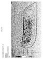
- FIG. 5 and Table 2 below show experimental results for radiant heat performance based on the comparison of internal part and surface temperatures of each lens of the conventional lighting device for the vehicle having the fan and the lighting device for the vehicle according to still another embodiment of the present invention.
- [Table 2] Division ⁇ T 10°C Reaching Time (min) Maximum Temperature of Lens Surface (°C) Conventional Lighting Device (having a fan) 64 36.6 Lighting device according to the present embodiment of the invention 18 39.8
- the lighting device for the vehicle according to the present embodiment of the invention in which the fan is removed can increase the internal part and surface temperature in a shorter time compared to the conventional lighting device for the vehicle having the fan, and it can also increase a maximum temperatures of the internal part and surface of the lens to be higher.
- the lighting device for the vehicle according to the present embodiment of the invention has a high radiant heat property and radiation rate compared to the conventional lighting device for the vehicle. Furthermore, in spite of the removal of the fan, the excellent radiant heat effect can be realized, and the effects such as snow melting causing the melting of snow collected on the optical substrate, defrosting, demisting, and defogging can be also realized.
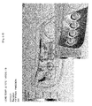
- FIG. 6 illustrates transmission simulation results for outer lenses of a lighting device for a vehicle A according to still another embodiment of the present invention in which a thermoplastic resin is applied to the second member, and a lighting device for a vehicle B to which a bezel made of a general plastic material is applied.
- the outer lenses under the same conditions are mounted to both A and B.
- a thermoplastic resin having a thermal conductivity of 5W/mK is applied
- B a polycarbonate having a thermal conductivity of 0.2W/mK is applied.
- A can additionally radiate the heat of 4W compared to B.
- radiant heat efficiency is improved by the second member, so a heat flux of an external part of the lens increases.
- the effects such as snow melting, defrosting, demisting and defogging can be realized.
- FIG. 7 illustrates experimental results for thermal resistance of a radiating device having no surface treatment layer, and a radiating device having a surface treatment layer according to still further another exemplary embodiment of the present invention.
- the radiating device according to the present embodiment of the invention in which the surface treatment layer is formed by anodizing processing, carbon nanotube (CNT) or silicone coating, power coating or the like can increase a radiation rate up to 20% or more to the fullest compared to the radiating device in which the surface treatment layer is not formed. Accordingly, although a radiative emission rate of the second member is low, a radiation rate can be improved thanks to the surface treatment layer formed on the surface of the first member.
- CNT carbon nanotube
- the fan can be removed, and due to the removal of the fan, a cost and a weight can be reduced, and space utilization can be improved. Furthermore, thanks to the radiation of heat through the second member, the effects of an optical member such as snow melting, defrosting, demisting and defogging can be realized.
- first radiating module and the second radiating module are integrally formed by insert injection molding, although the fan and the heat sink are removed, a radiant heat property can be improved.
- the surface treatment layer is formed on the surface of the first member, although the radiative emission rate of the second member is low, the heat radiation effect can be improved thanks to the first member.
Landscapes
- Engineering & Computer Science (AREA)
- General Engineering & Computer Science (AREA)
- Non-Portable Lighting Devices Or Systems Thereof (AREA)
- Arrangement Of Elements, Cooling, Sealing, Or The Like Of Lighting Devices (AREA)
- Lighting Device Outwards From Vehicle And Optical Signal (AREA)
- Physics & Mathematics (AREA)
- Thermal Sciences (AREA)
- Mechanical Engineering (AREA)
Abstract
Description
- Embodiments of the present invention relate to a radiating device, a lighting device including the same, and a lighting device for a vehicle.
- A light emitting diode (LED) device is directed to converting an electrical signal to infrared rays or light using the properties of a compound semiconductor. Unlike a fluorescent lamp, the LED device does not use any harmful substances such as mercury, which results in less environment contamination, and has an advantage that its life span is longer as compared to a conventional light source. The LED device also consumes low electric power as compared to a conventional light source, and shows excellent visibility and low glariness thanks to a high color temperature. Thus, the LED device has been widely used as a light source of a head lamp for a vehicle.
- However, a head lamp for a vehicle shows a basic environmental temperature of approximately about 80°C due to the heat of an engine, and is vulnerable to the radiation of heat because it is sealed, so an increase in its internal temperature has an influence on the LED's life span. Accordingly, a radiating system with high performance capable of effectively emitting heat generated from the LED is needed, so a fan for emitting the heat generated from the LED is adopted.
-
FIG. 1 is a view showing a conventional radiant heat structure for a vehicle headlamp. - As illustrated in
FIG. 1 , the conventional radiant heat structure for the vehicle headlamp includes: anLED module 20 formed in an inner side of a housing of the head lamp; aheat sink 30 formed at a bottom surface of theLED module 20; and acooling fan 40 installed at a lower part of theheat sink 30. - That is, the conventional radiant heat structure for the vehicle head lamp enables the heat generated from the LED module to be emitted to the outside through the
heat sink 30 formed at the bottom surface of theLED module 20, and has improved radiant heat efficiency by cooling theheat sink 30 with thecooling pan 40. - However, as illustrated in
FIG. 1 , the conventional radiating structure for the vehicle headlamp is problematic in that a cost and a weight of the vehicle are increased and space utilization is reduced because theseparate cooling fan 40 is mounted, and a cooling property is reduced because hot windy is generated in a case where thecooling fan 40 is used for long hours. - Furthermore, the lifespan of the cooling fan as well as the lifespan of the LED may become a problem, and there is also a problem that a separate electric motor is applied to the LED headlamp which pursues for low power.
- Moreover, unlike a high intensity discharge (HID) or a halogen light source, the LED hardly generates infrared rays or ultraviolet rays, so it is also problematic that freezing of the headlamp is caused due to the snow and the like.
- An aspect of embodiments of the present invention provides a radiating device and a lighting device that can reduce a production cost and a weight and can improve efficiency of space utilization by forming a second radiating module composed of different thermal conductive materials and removing a fan, and can also realize the effects of an optical member such as snow melting, defrosting, demisting and defogging by radiating heat to a light emitting space.
- An aspect of embodiments of the present invention also provides a radiating device and a lighting device that can increase a radiant heat property by integrally forming a first radiating module and a second radiating module through insert injection molding.
- According to an aspect of embodiments of the present invention, there is provided a radiating device, including: a first radiating module configured to receive heat generated from a light source module; and a second radiating module including a first member extending to the first heat dissipation module and transmitting the received heat, and a second member configured to form a light emitting space and to radiate the heat transmitted from the first member to the light emitting space.
- The accompanying drawings are included to provide a further understanding of the present invention, and are incorporated in and constitute a part of this specification. The drawings illustrate exemplary embodiments of the present invention and, together with the description, serve to explain principles of the present invention. In the drawings:
-
FIG. 1 is a view showing a conventional radiant heat structure for a vehicle headlamp; -
FIG. 2 through FIG. 4 illustrate various embodiments for a structure of a lighting device including a radiating device according to an embodiment of the present invention; -
FIG. 5 illustrates experimental results for radiant heat performance of a conventional lighting device for a vehicle and a lighting device for a vehicle according to another embodiment of the present invention; -
FIG. 6 illustrates transmission simulation results for each outer lens of a lighting device for a vehicle to which a bezel made of a general plastic material is applied and a lighting device for a vehicle according to still another embodiment of the present invention to which a thermal conductive resin is applied; and -
FIG. 7 illustrates experimental results for thermal resistance of a radiating device having no surface treatment layer, and a radiating device having a surface treatment layer according to still further another embodiment of the present invention. - Embodiments according to the present invention will now be described more fully hereinafter with reference to the accompanying drawings so that those having ordinary skill in the art can easily embody. This invention may, however, be embodied in different forms and should not be construed as limited to the exemplary embodiments set forth herein. It is to be understood that the form of the present invention shown and described herein is to be taken as a preferred embodiment of the present invention and that various changes and modifications may be made in the invention without departing from the spirit and scope thereof. In the following description, it is to be noted that, when the functions of conventional elements and the detailed description of elements related with the present invention may make the gist of the present invention unclear, a detailed description of those elements will be omitted. The terms below are defined in consideration of the functions of the present invention, and the meaning of each term should be interpreted by judging the whole parts of the present specification. Wherever possible, the same reference numerals will be used throughout the drawings and the description to refer to the same or like parts.
- Embodiments of the present invention relate to a radiating device and a lighting device, and are intended to provide a structure of the radiating device and a structure of the lighting device that can remove a fan while improving a radiant heat effect by forming a second radiating module made of a thermal conductive resin and metal, and can realize the effects of an optical member such as the snow melting, defrosting, demisting and defogging.
- Moreover, the radiating device and the lighting device according to the embodiments of the present invention can be applied to various lamp devices such as a lighting device for a vehicle, a lighting device for home use, an industrial lighting device for which illuminating is required. For example, when the radiating device and the lighting device are applied to a lamp for a vehicle, they can be also applied to a head light, a rear light and the like. In addition this, the radiating device and the lighting device can be applied to all the lighting-related applications which have been already developed and then commercialized or which can be implemented according to the technology advances.
-
FIG. 2 illustrates one embodiment for a structure of a lighting device including a radiating device according to an embodiment of the present invention. - Referring to
FIG. 2 , the radiating device according to the present embodiment of the invention may include: a first radiatingmodule 100 configured to receive heat generated from alight source module 310; and a second radiatingmodule 200 configured to receive the heat received in and transmitted from the first radiatingmodule 100 and to radiate the heat to a light emitting space. Also, the lighting device according to the present embodiment of the invention may include: anoptical member 320 fixed to an end of the second radiatingmodule 200 within ahousing 330; and alight source module 310 mounted on the first radiatingmodule 100 to emit light the optical member. - The first radiating
module 100 receives heat generated from thelight source module 310 mounted in an upper part thereof. Accordingly, the first radiatingmodule 100 may be made of a metal having high thermal conductivity, for example, Al, Cu, Ag, Cr, Ni and the like. As shown inFIG. 2 , although a heat sink is not disposed at a lower part of the first radiatingmodule 100, the present embodiment of the invention can realize an excellent radiant heat effect. Of course, it would be obvious to dispose the heat sink at the lower part of the first radiatingmodule 100 in order to improve a radiant heat property. - The
light source module 310 mounted in the upper part of the first radiating module includes a printed circuit board and a light emitting device mounted to the printed circuit board to emit light. The light emitting device may be a light emitting diode (LED). - The second radiating
module 200 may include: afirst member 210 extending to the first radiatingmodule 100 and transmitting the heat received in the first radiatingmodule 100; and asecond member 230 configured to form a light emitting space and to radiate the heat transmitted from thefirst member 210 to the light emitting space. Thefirst member 210 and thesecond member 230 may be manufactured in a separable structure. Although the drawing shows that thefirst member 210 is disposed at a lower part of thesecond member 230, the second member may be disposed at a lower part of the first member. - At this time, the first and
second members radiating module 100, thefirst member 210 may be made of a metal such as Al, Cu, Ag, Cr, Ni and the like having a high thermal conductivity. Thesecond member 230 may be made of a thermal conductive material having a higher radiative emission rate than that of thefirst member 210, and more specifically, it may be made of a thermoplastic resin or a thermal conductive filler composed of any one of polyphenylene sulfide (PPS), a liquid crystal polymer (LCP), polycarbonate (PC) and nylon. At this time, the thermal conductive filler may be composed of a combination of metal series such as a metal oxide, a metal carbide, a metal powder and the like, graphite, carbon series such as a carbon fiber and the like, or ceramic metal carbon series. - The
optical member 320 is fixed to an end part of the second member to emit light to the outside. Theoptical member 320 may include all optical substrates such as a lens, a transparent substrate, a translucent substrate and the like which emit light emitted from a light source to the outside. Accordingly, a lighting device for a vehicle may be an optical member for a vehicle, for example, an outer lens in a head lamp or a rear lamp. - Also, in the radiating device and the lighting device according to the present embodiments of the invention, a surface treatment layer (not drawn) may be formed on a surface of the
first member 210 in order to improve a radiative emission rate. At this time, the surface treatment layer may be formed by anodizing processing, carbon nanotube (CNT) or silicone coating, and powder coating, and may be formed such that the more the surface treatment layer is spaced apart from the first radiatingmodule 100, the more radiative emission rate increases. - In accordance with the present embodiment of the invention, the heat generated from the
light source module 310 is received and transmitted by the first radiatingmodule 100 and thefirst member 210 which are made of the thermal conductive metal, and is emitted through thesecond member 230 including the thermoplastic resin. In particular, although direct heat transfer through thesecond member 230 is low compared to that of thefirst member 210 made of the material having the high thermal conductivity, since thesecond member 230 is made of the thermal conductive material having the high radiative emission rate, a greater amount of heat than that of thefirst member 210 is radiated to the light emitting space. Thus, thanks to the heat radiated to the light emitting space, a surface temperature of theoptical member 320 increases, thereby melting of snow, ice formation and the like being present on the surface of theoptical member 320, defrosting, demisting, defogging and the like. Furthermore, unlike the conventional radiating device and lighting device, although the present embodiments of the invention have no fan, the radiant heat effect can be improved. Furthermore, as the fan is removed, a production cost and a weight can be reduced, and space utilization can be also improved. -
FIG. 3 andFIG. 4 illustrate other embodiments for the structure of a lighting device including a radiating device according to other embodiments of the present invention. The description on repeated elements with those ofFIG. 2 will be hereinafter omitted, and the structure will be described based on a difference. -
FIG. 3 is a side sectional view showing a structure in which thefirst radiating module 100 and thesecond radiating module 200 are integrally formed by insert injection molding, andFIG. 4 is a side sectional view showing a structure in which aheat sink 340 is added to the lighting device ofFIG. 3 . - In
FIG. 2 , the thermoplastic resin applied to thesecond member 230 has anisotropy due to the thermal conductive filler. It is not easy for the general thermal conductive resin to transmit heat in a vertical direction because thermal conductivity in a through-plane direction is relatively low compared to that in an in-plane direction, and contact resistance between thefirst member 210 and thesecond member 230 is high, so radiant heat efficiency can be reduced. Thus, in the other embodiment of the present invention, as shown inFIG. 3 , as thefirst radiating module 100 and thesecond radiating module 200 are integrally formed by insert injection molding, heat transfer may be easily conducted, and as contact resistance between thefirst member 210 and thesecond member 230 is reduced, an assembly property as well as a radiant heat effect can be improved. - In particular, a
laminated portion 220 in which thefirst member 210 and thesecond member 230 are laminated may be formed in thesecond radiating module 200. Thelaminated portion 220 may have a structure in which thesecond member 230 is laminated on an upper surface of thefirst member 210. In addition to this, in order to increase a radiation rate and prevent glariness from being generated at the outside, the laminated portion may have a structure, as illustrated inFIG. 3 , in which the first member is laminated on an upper surface of thesecond member 230. As a result, thefirst member 210 made of the metal having the high thermal conductivity may lead the transmission of heat, and thesecond member 230 may radiate the heat to the light emitting space. - Although
FIG. 3 illustrates that thefirst radiating module 100 and thesecond radiating module 200 are integrally formed by the insert injection molding, the structure is not limited thereto. As another embodiment, only thefirst member 210 and thesecond member 230 may be integrally formed by insert injection molding or only thesecond member 230 and thelaminated portion 220 may be integrally formed by insert injection molding. - Table 1 below shows the comparison of thermal resistance for thermal diffusion members of the lighting device shown in
FIG. 3 according to the present embodiment of the invention and the conventional lighting device for a vehicle.[Table 1] Division Main Heat Source Thermal Diffusion Member Thermal Resistance (Rsa) Conventional lighting device 1 (A) 1. LED Heat Pipe 3K/ W 2. Electric Motor Heat Sink Conventional lighting device 2 (B) 1. LED Fan 2.5 K/W Heat Sink Conventional lighting device 3 (C) 1. LED Heat Sink 2.9 K/ W 2. Electric Motor 3. Engine Lighting device according to the present embodiment of the invention (D) 1. LED First and Second Radiating 2.27 K/ W 2. Engine Module - In Table 1 above, (A) has the LED, the electric motor, the engine as a main heat source and diffuses heat through the heat sink of the heat pipe, (B) has the LED as a main heat source and diffuses heat through the fan and the heat sink, (C) has the LED, the electric motor and the engine as a main heat source and diffuses heat through the heat sink, and (D) according to the present embodiment of the invention has the LED and the engine as a main heat source and diffuses heat through the first radiating module and the second radiating module.
- As shown in Table 1 above, although the lighting device according to the present embodiment of the invention has no fan or heat sink, it shows lowest thermal resistance. Thus, it can be confirmed that the lighting device has the best radiant heat performance. Thanks to the radiant heat performance of the present embodiment of the invention, the effects such as snow melting, defrosting, demisting, and defogging can be realized.
- Moreover, (A) has a problem such as a high weight because the heat pipe and the heat sink are used as a heat diffusion member, (B) has a problem such as the credibility and noise of a fan, and a high cost because the fan and the heat sink are used as a heat diffusion member, (C) has a problem such as a high weight because only the heat sink as a large-sized radiating plate is used as a heat diffusion member. However, in the present embodiment of the invention, although the fan and the heat sink are not provided, in addition to the excellent radiant performance, the weight can be maximally reduced up to 80%, and the problem such as the noise and credibility can be also settled.
- As explained in
FIG. 2 , the radiating device and the lighting device according to the present embodiments of the invention can realize the excellent radiant effect even without the heat sink. However, in order to improve the radiant heat property, as shown inFIG. 4 , theheat sink 340 may be disposed at a lower part of thefirst radiating module 100. Also, the surface treatment layer explained inFIG. 2 may be also applied to the lighting device ofFIG. 3 andFIG. 4 . -
FIG. 5 and Table 2 below show experimental results for radiant heat performance based on the comparison of internal part and surface temperatures of each lens of the conventional lighting device for the vehicle having the fan and the lighting device for the vehicle according to still another embodiment of the present invention.[Table 2] Division ΔT=10°C Reaching Time (min) Maximum Temperature of Lens Surface (°C) Conventional Lighting Device (having a fan) 64 36.6 Lighting device according to the present embodiment of the invention 18 39.8 - In
FIG. 5 and Table 2, the lighting device for the vehicle according to the present embodiment of the invention in which the fan is removed can increase the internal part and surface temperature in a shorter time compared to the conventional lighting device for the vehicle having the fan, and it can also increase a maximum temperatures of the internal part and surface of the lens to be higher. Thus, the lighting device for the vehicle according to the present embodiment of the invention has a high radiant heat property and radiation rate compared to the conventional lighting device for the vehicle. Furthermore, in spite of the removal of the fan, the excellent radiant heat effect can be realized, and the effects such as snow melting causing the melting of snow collected on the optical substrate, defrosting, demisting, and defogging can be also realized. -
FIG. 6 illustrates transmission simulation results for outer lenses of a lighting device for a vehicle A according to still another embodiment of the present invention in which a thermoplastic resin is applied to the second member, and a lighting device for a vehicle B to which a bezel made of a general plastic material is applied. - In
FIG. 6 , the outer lenses under the same conditions (refractive index: 1.56, absorption coefficient: 3.8[cm-1], and scattering coefficient: 12.8[cm-1]) are mounted to both A and B. In A, as the second member, a thermoplastic resin having a thermal conductivity of 5W/mK is applied, and in B, a polycarbonate having a thermal conductivity of 0.2W/mK is applied. As a result, it is shown that A can additionally radiate the heat of 4W compared to B. Thus, in the present embodiment of the invention, radiant heat efficiency is improved by the second member, so a heat flux of an external part of the lens increases. Thus, the effects such as snow melting, defrosting, demisting and defogging can be realized. -
FIG. 7 illustrates experimental results for thermal resistance of a radiating device having no surface treatment layer, and a radiating device having a surface treatment layer according to still further another exemplary embodiment of the present invention. - In
FIG. 7 , it is shown that the radiating device according to the present embodiment of the invention in which the surface treatment layer is formed by anodizing processing, carbon nanotube (CNT) or silicone coating, power coating or the like can increase a radiation rate up to 20% or more to the fullest compared to the radiating device in which the surface treatment layer is not formed. Accordingly, although a radiative emission rate of the second member is low, a radiation rate can be improved thanks to the surface treatment layer formed on the surface of the first member. - As set forth above, according to embodiments of the invention, as the second radiating module including different thermal conductive materials from each other is provided, the fan can be removed, and due to the removal of the fan, a cost and a weight can be reduced, and space utilization can be improved. Furthermore, thanks to the radiation of heat through the second member, the effects of an optical member such as snow melting, defrosting, demisting and defogging can be realized.
- Furthermore, since the first radiating module and the second radiating module are integrally formed by insert injection molding, although the fan and the heat sink are removed, a radiant heat property can be improved.
- Moreover, since the surface treatment layer is formed on the surface of the first member, although the radiative emission rate of the second member is low, the heat radiation effect can be improved thanks to the first member.
- As previously described, in the detailed description of the invention, having described the detailed exemplary embodiments of the invention, it should be apparent that modifications and variations can be made by persons skilled without deviating from the spirit or scope of the invention. Therefore, it is to be understood that the foregoing is illustrative of the present invention and is not to be construed as limited to the specific embodiments disclosed, and that modifications to the disclosed embodiments, as well as other embodiments, are intended to be included within the scope of the appended claims and their equivalents.
Claims (15)
- A radiating device comprising:a first radiating module configured to receive heat generated from a light source module; anda second radiating module that comprises a first member extending to the first radiating module and transmitting the received heat, and a second member configured to emit the heat transmitted from the first member to a light emitting space.
- The radiating device of claim 1, wherein the first member and the second member are made of materials having different thermal conductivities.
- The radiating device of claim 1 or 2, wherein the second member is made of a material having a higher radiative emission rate than that of the first member.
- The radiating device of any one of claims 1 to 3, wherein the first radiating module and the first member comprise a thermal conductive metal.
- The radiating device of claim 4, wherein the second member comprises a thermal conductive material.
- The radiating device of claim 5, wherein the thermal conductive material is any one of polyphenylene sulfide (PPS), a liquid crystal polymer (LCP), polycarbonate (PC) and nylon.
- The radiating device of any one of claims 1 to 6, further comprising a surface treatment layer for an increase in radiative emission rate formed on a surface of the first member.
- The radiating device of claim 7, wherein the surface treatment layer is configured such that a radiative emission rate increases as the surface treatment layer is away from the first radiating module.
- The radiating device of claim 7 or 8, wherein the surface treatment layer is an anodizing processing layer or a carbon nanotube (CNT) or silicone coating layer.
- The radiating device of any one of claims 1 to 9, wherein at least one pair of the first and second members, and the first and second radiating modules have an integral structure by insert injection molding.
- The radiating device of any one of claims 1 to 10, wherein the second radiating module further comprises a laminated portion in which the first member and the second member are laminated.
- The radiating device of claim 11, wherein the second member and the laminated portion have an integral structure by insert injection molding.
- The radiating device of any one of claims 1 to 12, further comprising a heat sink formed at a lower part of the first radiating module.
- A lighting device, comprising:the radiating device of any one of claims 1 to 13;a light source module mounted to the first radiating module to emit light; andan optical member formed at an end part of the second member.
- A lighting device for a vehicle, comprising:the radiating device of claim 14;an optical member for a vehicle fixed to the end part of the second member; anda light source module mounted to the first radiating module to emit light to the optical member for the vehicle.
Applications Claiming Priority (1)
| Application Number | Priority Date | Filing Date | Title |
|---|---|---|---|
| KR1020130012308A KR102072429B1 (en) | 2013-02-04 | 2013-02-04 | Illuminating device for vehicle, radiating device and illuminating device |
Publications (3)
| Publication Number | Publication Date |
|---|---|
| EP2762771A2 true EP2762771A2 (en) | 2014-08-06 |
| EP2762771A3 EP2762771A3 (en) | 2016-08-17 |
| EP2762771B1 EP2762771B1 (en) | 2021-12-29 |
Family
ID=50028876
Family Applications (1)
| Application Number | Title | Priority Date | Filing Date |
|---|---|---|---|
| EP14153233.3A Active EP2762771B1 (en) | 2013-02-04 | 2014-01-30 | Lighting device for vehicle and lighting device |
Country Status (5)
| Country | Link |
|---|---|
| US (1) | US9869446B2 (en) |
| EP (1) | EP2762771B1 (en) |
| JP (1) | JP5774737B2 (en) |
| KR (1) | KR102072429B1 (en) |
| CN (1) | CN103968313B (en) |
Cited By (4)
| Publication number | Priority date | Publication date | Assignee | Title |
|---|---|---|---|---|
| FR3039703A1 (en) * | 2015-07-27 | 2017-02-03 | Commissariat Energie Atomique | PASSIVE THERMAL SYSTEM BASED ON NANO-ELEMENTS |
| CN108587155A (en) * | 2018-05-25 | 2018-09-28 | 郑州智锦电子科技有限公司 | A kind of heat conduction polyamide compoiste material and preparation method thereof |
| EP3578873A4 (en) * | 2017-02-24 | 2020-01-22 | Mazda Motor Corporation | Lighting fixture for vehicle |
| EP3671024A1 (en) * | 2018-12-21 | 2020-06-24 | Valeo Iluminacion, S.A. | Heat transfer system for a lighting module of a motor vehicle |
Families Citing this family (12)
| Publication number | Priority date | Publication date | Assignee | Title |
|---|---|---|---|---|
| CN108349430B (en) * | 2015-10-27 | 2021-06-22 | 株式会社小糸制作所 | Lighting device for vehicle, vehicle system, and vehicle |
| JP2017126442A (en) * | 2016-01-13 | 2017-07-20 | ウシオ電機株式会社 | Fluorescent light source device |
| FR3051889B1 (en) * | 2016-05-31 | 2020-03-06 | Valeo Vision | LIGHTING AND / OR SIGNALING DEVICE FOR A MOTOR VEHICLE EQUIPPED WITH A COOLED LIGHT MODULE USING AN AIRFLOW GENERATOR |
| KR102010497B1 (en) | 2017-03-06 | 2019-08-14 | 조수동 | Chemical reaction leak sensor sensing leak material by chemical reaction |
| US10429026B2 (en) * | 2017-06-16 | 2019-10-01 | GM Global Technology Operations LLC | Lamp assembly with anisotropic heat spreader and vehicle having the same |
| JP7168354B2 (en) * | 2018-06-18 | 2022-11-09 | スタンレー電気株式会社 | vehicle lamp |
| CN110887017A (en) * | 2018-09-11 | 2020-03-17 | 常州星宇车灯股份有限公司 | Method for preventing fog of car lamp |
| CN109595966A (en) * | 2018-11-24 | 2019-04-09 | 苏州驿力机车科技股份有限公司 | Radiator heat-dissipation fin |
| CN109595967A (en) * | 2018-11-24 | 2019-04-09 | 苏州驿力机车科技股份有限公司 | The radiator heat-dissipation fin of high efficiency and heat radiation |
| WO2022006247A1 (en) * | 2020-07-02 | 2022-01-06 | Materialwerks, Llc | Unitary multi-optic systems with optical barriers |
| KR20240131071A (en) | 2023-02-23 | 2024-08-30 | 박종식 | Chemical leakage detection method and chemical leakage sensor device using complex detection |
| JP2025071697A (en) * | 2023-10-23 | 2025-05-08 | スタンレー電気株式会社 | Vehicular head lamp |
Family Cites Families (19)
| Publication number | Priority date | Publication date | Assignee | Title |
|---|---|---|---|---|
| US4555748A (en) * | 1982-10-28 | 1985-11-26 | General Electric Company | Truncated motor vehicle headlamp |
| DE10258624B3 (en) * | 2002-12-16 | 2004-07-15 | Daimlerchrysler Ag | Headlamp unit for a motor vehicle |
| US6976769B2 (en) * | 2003-06-11 | 2005-12-20 | Cool Options, Inc. | Light-emitting diode reflector assembly having a heat pipe |
| JP4590283B2 (en) * | 2004-05-21 | 2010-12-01 | シャープ株式会社 | Backlight unit and liquid crystal display device including the same |
| TWI342373B (en) * | 2004-10-21 | 2011-05-21 | Panasonic Corp | Illumination device |
| JP4270153B2 (en) * | 2005-04-05 | 2009-05-27 | 市光工業株式会社 | Vehicle lighting |
| US7478932B2 (en) * | 2005-11-29 | 2009-01-20 | Visteon Global Technologies, Inc. | Headlamp assembly having cooling channel |
| JP2007234449A (en) * | 2006-03-02 | 2007-09-13 | Toray Ind Inc | Vehicle lighting |
| JP2007242291A (en) * | 2006-03-06 | 2007-09-20 | Ichikoh Ind Ltd | Vehicle lighting |
| JP4582803B2 (en) * | 2006-03-31 | 2010-11-17 | スタンレー電気株式会社 | Vehicle lighting |
| DE102007050924B4 (en) * | 2007-10-23 | 2009-11-26 | Oechsler Ag | LED-equipped luminaire module, in particular for motor vehicles |
| WO2009090700A1 (en) * | 2008-01-17 | 2009-07-23 | Mitsubishi Electric Corporation | Vehicle headlamp |
| CN101532657A (en) * | 2008-03-13 | 2009-09-16 | 富士迈半导体精密工业(上海)有限公司 | Illuminating apparatus |
| JP2010102997A (en) * | 2008-10-24 | 2010-05-06 | Stanley Electric Co Ltd | Led lighting fixture for vehicle |
| JP2011028906A (en) * | 2009-07-22 | 2011-02-10 | Stanley Electric Co Ltd | Led lighting tool for vehicle |
| KR101043278B1 (en) * | 2009-08-26 | 2011-06-21 | 현대모비스 주식회사 | Car headlamps |
| JP2012209058A (en) * | 2011-03-29 | 2012-10-25 | Kobe Steel Ltd | Heat sink for led bulb |
| DE102011077668B4 (en) * | 2011-06-16 | 2018-03-08 | Trilux Gmbh & Co. Kg | Lamp with thermal coupling element made of thermally conductive plastic |
| KR20130025718A (en) * | 2011-09-02 | 2013-03-12 | 삼성전자주식회사 | Light emitting device lamp |
-
2013
- 2013-02-04 KR KR1020130012308A patent/KR102072429B1/en active Active
-
2014
- 2014-01-29 CN CN201410043761.5A patent/CN103968313B/en active Active
- 2014-01-29 JP JP2014014401A patent/JP5774737B2/en active Active
- 2014-01-30 EP EP14153233.3A patent/EP2762771B1/en active Active
- 2014-02-04 US US14/172,498 patent/US9869446B2/en active Active
Non-Patent Citations (1)
| Title |
|---|
| None |
Cited By (4)
| Publication number | Priority date | Publication date | Assignee | Title |
|---|---|---|---|---|
| FR3039703A1 (en) * | 2015-07-27 | 2017-02-03 | Commissariat Energie Atomique | PASSIVE THERMAL SYSTEM BASED ON NANO-ELEMENTS |
| EP3578873A4 (en) * | 2017-02-24 | 2020-01-22 | Mazda Motor Corporation | Lighting fixture for vehicle |
| CN108587155A (en) * | 2018-05-25 | 2018-09-28 | 郑州智锦电子科技有限公司 | A kind of heat conduction polyamide compoiste material and preparation method thereof |
| EP3671024A1 (en) * | 2018-12-21 | 2020-06-24 | Valeo Iluminacion, S.A. | Heat transfer system for a lighting module of a motor vehicle |
Also Published As
| Publication number | Publication date |
|---|---|
| JP2014154554A (en) | 2014-08-25 |
| CN103968313A (en) | 2014-08-06 |
| KR102072429B1 (en) | 2020-02-03 |
| US9869446B2 (en) | 2018-01-16 |
| EP2762771A3 (en) | 2016-08-17 |
| CN103968313B (en) | 2017-05-03 |
| EP2762771B1 (en) | 2021-12-29 |
| JP5774737B2 (en) | 2015-09-09 |
| US20140218950A1 (en) | 2014-08-07 |
| KR20140099643A (en) | 2014-08-13 |
Similar Documents
| Publication | Publication Date | Title |
|---|---|---|
| EP2762771B1 (en) | Lighting device for vehicle and lighting device | |
| CN202469561U (en) | lighting device | |
| US7771082B2 (en) | Lamp with heat conducting structure and lamp cover thereof | |
| US20110305025A1 (en) | Led-based lamps and thermal management systems therefor | |
| KR102071338B1 (en) | Electric lamp having reflector for transferring heat from light source | |
| US20150036369A1 (en) | Automobile led head lamp module using flexible substrate and heat sink structure thereof | |
| CN101839413A (en) | LED fluorescent lamp | |
| EP3479011B1 (en) | An enclosure for lighting systems | |
| EP3627046A1 (en) | Light weight radiant heat structure of thermoelectric polymer heat sink and manufacturing method of the same | |
| RU2608566C2 (en) | Lighting device with printed circuit board holder | |
| WO2009043849A1 (en) | Backlight module for liquid crystal display | |
| CN102374509A (en) | Liquid crystal display device, backlight module and heat radiating method thereof | |
| CN105849462B (en) | Heat sinks and lighting | |
| KR101321581B1 (en) | Light emitting diode lamp | |
| CN207034791U (en) | Fish-collecting lamp and its light-emitting module | |
| KR20160025062A (en) | Illuminating device for vehicle | |
| KR100954997B1 (en) | Led illumination lamp | |
| KR100962249B1 (en) | Bar LED Lighting | |
| KR20100102317A (en) | High power light emitting diode lamp | |
| CN102478171B (en) | LED light lamp | |
| CN105757530A (en) | High-power projection LED optical engine based on high-heat-dissipation substrate and integrated packaging technology | |
| CN103557466B (en) | LED (Light-Emitting Diode) fluorescent lamp | |
| US20150009674A1 (en) | Structures subjected to thermal energy and thermal management methods therefor | |
| KR20150009063A (en) | Cooling module for vehicle and illuminating device using the same | |
| JP2015084125A (en) | Traffic signal structure provided against snow accretion |
Legal Events
| Date | Code | Title | Description |
|---|---|---|---|
| PUAI | Public reference made under article 153(3) epc to a published international application that has entered the european phase |
Free format text: ORIGINAL CODE: 0009012 |
|
| 17P | Request for examination filed |
Effective date: 20140331 |
|
| AK | Designated contracting states |
Kind code of ref document: A2 Designated state(s): AL AT BE BG CH CY CZ DE DK EE ES FI FR GB GR HR HU IE IS IT LI LT LU LV MC MK MT NL NO PL PT RO RS SE SI SK SM TR |
|
| AX | Request for extension of the european patent |
Extension state: BA ME |
|
| PUAL | Search report despatched |
Free format text: ORIGINAL CODE: 0009013 |
|
| AK | Designated contracting states |
Kind code of ref document: A3 Designated state(s): AL AT BE BG CH CY CZ DE DK EE ES FI FR GB GR HR HU IE IS IT LI LT LU LV MC MK MT NL NO PL PT RO RS SE SI SK SM TR |
|
| AX | Request for extension of the european patent |
Extension state: BA ME |
|
| RIC1 | Information provided on ipc code assigned before grant |
Ipc: F21S 8/10 20060101AFI20160713BHEP |
|
| RBV | Designated contracting states (corrected) |
Designated state(s): AL AT BE BG CH CY CZ DE DK EE ES FI FR GB GR HR HU IE IS IT LI LT LU LV MC MK MT NL NO PL PT RO RS SE SI SK SM TR |
|
| RAP1 | Party data changed (applicant data changed or rights of an application transferred) |
Owner name: LG INNOTEK CO., LTD. |
|
| STAA | Information on the status of an ep patent application or granted ep patent |
Free format text: STATUS: EXAMINATION IS IN PROGRESS |
|
| 17Q | First examination report despatched |
Effective date: 20200211 |
|
| REG | Reference to a national code |
Ref country code: DE Ref legal event code: R079 Ref document number: 602014081885 Country of ref document: DE Free format text: PREVIOUS MAIN CLASS: F21S0008100000 Ipc: F21S0045470000 |
|
| RIC1 | Information provided on ipc code assigned before grant |
Ipc: F21S 45/47 20180101AFI20210519BHEP Ipc: F21S 45/60 20180101ALI20210519BHEP |
|
| GRAP | Despatch of communication of intention to grant a patent |
Free format text: ORIGINAL CODE: EPIDOSNIGR1 |
|
| STAA | Information on the status of an ep patent application or granted ep patent |
Free format text: STATUS: GRANT OF PATENT IS INTENDED |
|
| INTG | Intention to grant announced |
Effective date: 20210719 |
|
| GRAS | Grant fee paid |
Free format text: ORIGINAL CODE: EPIDOSNIGR3 |
|
| GRAA | (expected) grant |
Free format text: ORIGINAL CODE: 0009210 |
|
| STAA | Information on the status of an ep patent application or granted ep patent |
Free format text: STATUS: THE PATENT HAS BEEN GRANTED |
|
| AK | Designated contracting states |
Kind code of ref document: B1 Designated state(s): AL AT BE BG CH CY CZ DE DK EE ES FI FR GB GR HR HU IE IS IT LI LT LU LV MC MK MT NL NO PL PT RO RS SE SI SK SM TR |
|
| REG | Reference to a national code |
Ref country code: GB Ref legal event code: FG4D |
|
| REG | Reference to a national code |
Ref country code: CH Ref legal event code: EP |
|
| REG | Reference to a national code |
Ref country code: AT Ref legal event code: REF Ref document number: 1458941 Country of ref document: AT Kind code of ref document: T Effective date: 20220115 |
|
| REG | Reference to a national code |
Ref country code: IE Ref legal event code: FG4D |
|
| REG | Reference to a national code |
Ref country code: DE Ref legal event code: R096 Ref document number: 602014081885 Country of ref document: DE |
|
| REG | Reference to a national code |
Ref country code: LT Ref legal event code: MG9D |
|
| PG25 | Lapsed in a contracting state [announced via postgrant information from national office to epo] |
Ref country code: RS Free format text: LAPSE BECAUSE OF FAILURE TO SUBMIT A TRANSLATION OF THE DESCRIPTION OR TO PAY THE FEE WITHIN THE PRESCRIBED TIME-LIMIT Effective date: 20211229 Ref country code: LT Free format text: LAPSE BECAUSE OF FAILURE TO SUBMIT A TRANSLATION OF THE DESCRIPTION OR TO PAY THE FEE WITHIN THE PRESCRIBED TIME-LIMIT Effective date: 20211229 Ref country code: FI Free format text: LAPSE BECAUSE OF FAILURE TO SUBMIT A TRANSLATION OF THE DESCRIPTION OR TO PAY THE FEE WITHIN THE PRESCRIBED TIME-LIMIT Effective date: 20211229 Ref country code: BG Free format text: LAPSE BECAUSE OF FAILURE TO SUBMIT A TRANSLATION OF THE DESCRIPTION OR TO PAY THE FEE WITHIN THE PRESCRIBED TIME-LIMIT Effective date: 20220329 |
|
| REG | Reference to a national code |
Ref country code: NL Ref legal event code: MP Effective date: 20211229 |
|
| REG | Reference to a national code |
Ref country code: AT Ref legal event code: MK05 Ref document number: 1458941 Country of ref document: AT Kind code of ref document: T Effective date: 20211229 |
|
| PG25 | Lapsed in a contracting state [announced via postgrant information from national office to epo] |
Ref country code: SE Free format text: LAPSE BECAUSE OF FAILURE TO SUBMIT A TRANSLATION OF THE DESCRIPTION OR TO PAY THE FEE WITHIN THE PRESCRIBED TIME-LIMIT Effective date: 20211229 Ref country code: NO Free format text: LAPSE BECAUSE OF FAILURE TO SUBMIT A TRANSLATION OF THE DESCRIPTION OR TO PAY THE FEE WITHIN THE PRESCRIBED TIME-LIMIT Effective date: 20220329 Ref country code: LV Free format text: LAPSE BECAUSE OF FAILURE TO SUBMIT A TRANSLATION OF THE DESCRIPTION OR TO PAY THE FEE WITHIN THE PRESCRIBED TIME-LIMIT Effective date: 20211229 Ref country code: HR Free format text: LAPSE BECAUSE OF FAILURE TO SUBMIT A TRANSLATION OF THE DESCRIPTION OR TO PAY THE FEE WITHIN THE PRESCRIBED TIME-LIMIT Effective date: 20211229 Ref country code: GR Free format text: LAPSE BECAUSE OF FAILURE TO SUBMIT A TRANSLATION OF THE DESCRIPTION OR TO PAY THE FEE WITHIN THE PRESCRIBED TIME-LIMIT Effective date: 20220330 |
|
| PG25 | Lapsed in a contracting state [announced via postgrant information from national office to epo] |
Ref country code: NL Free format text: LAPSE BECAUSE OF FAILURE TO SUBMIT A TRANSLATION OF THE DESCRIPTION OR TO PAY THE FEE WITHIN THE PRESCRIBED TIME-LIMIT Effective date: 20211229 |
|
| PG25 | Lapsed in a contracting state [announced via postgrant information from national office to epo] |
Ref country code: SM Free format text: LAPSE BECAUSE OF FAILURE TO SUBMIT A TRANSLATION OF THE DESCRIPTION OR TO PAY THE FEE WITHIN THE PRESCRIBED TIME-LIMIT Effective date: 20211229 Ref country code: SK Free format text: LAPSE BECAUSE OF FAILURE TO SUBMIT A TRANSLATION OF THE DESCRIPTION OR TO PAY THE FEE WITHIN THE PRESCRIBED TIME-LIMIT Effective date: 20211229 Ref country code: RO Free format text: LAPSE BECAUSE OF FAILURE TO SUBMIT A TRANSLATION OF THE DESCRIPTION OR TO PAY THE FEE WITHIN THE PRESCRIBED TIME-LIMIT Effective date: 20211229 Ref country code: PT Free format text: LAPSE BECAUSE OF FAILURE TO SUBMIT A TRANSLATION OF THE DESCRIPTION OR TO PAY THE FEE WITHIN THE PRESCRIBED TIME-LIMIT Effective date: 20220429 Ref country code: ES Free format text: LAPSE BECAUSE OF FAILURE TO SUBMIT A TRANSLATION OF THE DESCRIPTION OR TO PAY THE FEE WITHIN THE PRESCRIBED TIME-LIMIT Effective date: 20211229 Ref country code: EE Free format text: LAPSE BECAUSE OF FAILURE TO SUBMIT A TRANSLATION OF THE DESCRIPTION OR TO PAY THE FEE WITHIN THE PRESCRIBED TIME-LIMIT Effective date: 20211229 Ref country code: CZ Free format text: LAPSE BECAUSE OF FAILURE TO SUBMIT A TRANSLATION OF THE DESCRIPTION OR TO PAY THE FEE WITHIN THE PRESCRIBED TIME-LIMIT Effective date: 20211229 |
|
| PG25 | Lapsed in a contracting state [announced via postgrant information from national office to epo] |
Ref country code: PL Free format text: LAPSE BECAUSE OF FAILURE TO SUBMIT A TRANSLATION OF THE DESCRIPTION OR TO PAY THE FEE WITHIN THE PRESCRIBED TIME-LIMIT Effective date: 20211229 Ref country code: AT Free format text: LAPSE BECAUSE OF FAILURE TO SUBMIT A TRANSLATION OF THE DESCRIPTION OR TO PAY THE FEE WITHIN THE PRESCRIBED TIME-LIMIT Effective date: 20211229 |
|
| REG | Reference to a national code |
Ref country code: CH Ref legal event code: PL |
|
| PG25 | Lapsed in a contracting state [announced via postgrant information from national office to epo] |
Ref country code: MC Free format text: LAPSE BECAUSE OF FAILURE TO SUBMIT A TRANSLATION OF THE DESCRIPTION OR TO PAY THE FEE WITHIN THE PRESCRIBED TIME-LIMIT Effective date: 20211229 Ref country code: IS Free format text: LAPSE BECAUSE OF FAILURE TO SUBMIT A TRANSLATION OF THE DESCRIPTION OR TO PAY THE FEE WITHIN THE PRESCRIBED TIME-LIMIT Effective date: 20220429 |
|
| REG | Reference to a national code |
Ref country code: DE Ref legal event code: R097 Ref document number: 602014081885 Country of ref document: DE |
|
| REG | Reference to a national code |
Ref country code: BE Ref legal event code: MM Effective date: 20220131 |
|
| PG25 | Lapsed in a contracting state [announced via postgrant information from national office to epo] |
Ref country code: LU Free format text: LAPSE BECAUSE OF NON-PAYMENT OF DUE FEES Effective date: 20220130 Ref country code: DK Free format text: LAPSE BECAUSE OF FAILURE TO SUBMIT A TRANSLATION OF THE DESCRIPTION OR TO PAY THE FEE WITHIN THE PRESCRIBED TIME-LIMIT Effective date: 20211229 Ref country code: AL Free format text: LAPSE BECAUSE OF FAILURE TO SUBMIT A TRANSLATION OF THE DESCRIPTION OR TO PAY THE FEE WITHIN THE PRESCRIBED TIME-LIMIT Effective date: 20211229 |
|
| PLBE | No opposition filed within time limit |
Free format text: ORIGINAL CODE: 0009261 |
|
| STAA | Information on the status of an ep patent application or granted ep patent |
Free format text: STATUS: NO OPPOSITION FILED WITHIN TIME LIMIT |
|
| GBPC | Gb: european patent ceased through non-payment of renewal fee |
Effective date: 20220329 |
|
| PG25 | Lapsed in a contracting state [announced via postgrant information from national office to epo] |
Ref country code: BE Free format text: LAPSE BECAUSE OF NON-PAYMENT OF DUE FEES Effective date: 20220131 |
|
| 26N | No opposition filed |
Effective date: 20220930 |
|
| PG25 | Lapsed in a contracting state [announced via postgrant information from national office to epo] |
Ref country code: LI Free format text: LAPSE BECAUSE OF NON-PAYMENT OF DUE FEES Effective date: 20220131 Ref country code: FR Free format text: LAPSE BECAUSE OF NON-PAYMENT OF DUE FEES Effective date: 20220228 Ref country code: CH Free format text: LAPSE BECAUSE OF NON-PAYMENT OF DUE FEES Effective date: 20220131 |
|
| PG25 | Lapsed in a contracting state [announced via postgrant information from national office to epo] |
Ref country code: IE Free format text: LAPSE BECAUSE OF NON-PAYMENT OF DUE FEES Effective date: 20220130 Ref country code: GB Free format text: LAPSE BECAUSE OF NON-PAYMENT OF DUE FEES Effective date: 20220329 |
|
| PG25 | Lapsed in a contracting state [announced via postgrant information from national office to epo] |
Ref country code: SI Free format text: LAPSE BECAUSE OF FAILURE TO SUBMIT A TRANSLATION OF THE DESCRIPTION OR TO PAY THE FEE WITHIN THE PRESCRIBED TIME-LIMIT Effective date: 20211229 |
|
| PG25 | Lapsed in a contracting state [announced via postgrant information from national office to epo] |
Ref country code: IT Free format text: LAPSE BECAUSE OF FAILURE TO SUBMIT A TRANSLATION OF THE DESCRIPTION OR TO PAY THE FEE WITHIN THE PRESCRIBED TIME-LIMIT Effective date: 20211229 |
|
| PG25 | Lapsed in a contracting state [announced via postgrant information from national office to epo] |
Ref country code: HU Free format text: LAPSE BECAUSE OF FAILURE TO SUBMIT A TRANSLATION OF THE DESCRIPTION OR TO PAY THE FEE WITHIN THE PRESCRIBED TIME-LIMIT; INVALID AB INITIO Effective date: 20140130 |
|
| PG25 | Lapsed in a contracting state [announced via postgrant information from national office to epo] |
Ref country code: MK Free format text: LAPSE BECAUSE OF FAILURE TO SUBMIT A TRANSLATION OF THE DESCRIPTION OR TO PAY THE FEE WITHIN THE PRESCRIBED TIME-LIMIT Effective date: 20211229 Ref country code: CY Free format text: LAPSE BECAUSE OF FAILURE TO SUBMIT A TRANSLATION OF THE DESCRIPTION OR TO PAY THE FEE WITHIN THE PRESCRIBED TIME-LIMIT Effective date: 20211229 |
|
| PG25 | Lapsed in a contracting state [announced via postgrant information from national office to epo] |
Ref country code: TR Free format text: LAPSE BECAUSE OF FAILURE TO SUBMIT A TRANSLATION OF THE DESCRIPTION OR TO PAY THE FEE WITHIN THE PRESCRIBED TIME-LIMIT Effective date: 20211229 |
|
| PG25 | Lapsed in a contracting state [announced via postgrant information from national office to epo] |
Ref country code: MT Free format text: LAPSE BECAUSE OF FAILURE TO SUBMIT A TRANSLATION OF THE DESCRIPTION OR TO PAY THE FEE WITHIN THE PRESCRIBED TIME-LIMIT Effective date: 20211229 |
|
| PGFP | Annual fee paid to national office [announced via postgrant information from national office to epo] |
Ref country code: DE Payment date: 20251222 Year of fee payment: 13 |