EP2762701A1 - Variable capacity-type turbocharger and assembly method for variable nozzle mechanism - Google Patents
Variable capacity-type turbocharger and assembly method for variable nozzle mechanism Download PDFInfo
- Publication number
- EP2762701A1 EP2762701A1 EP12837441.0A EP12837441A EP2762701A1 EP 2762701 A1 EP2762701 A1 EP 2762701A1 EP 12837441 A EP12837441 A EP 12837441A EP 2762701 A1 EP2762701 A1 EP 2762701A1
- Authority
- EP
- European Patent Office
- Prior art keywords
- pin
- variable nozzle
- nozzle mechanism
- bearing housing
- variable
- Prior art date
- Legal status (The legal status is an assumption and is not a legal conclusion. Google has not performed a legal analysis and makes no representation as to the accuracy of the status listed.)
- Granted
Links
Images


Classifications
-
- F—MECHANICAL ENGINEERING; LIGHTING; HEATING; WEAPONS; BLASTING
- F04—POSITIVE - DISPLACEMENT MACHINES FOR LIQUIDS; PUMPS FOR LIQUIDS OR ELASTIC FLUIDS
- F04D—NON-POSITIVE-DISPLACEMENT PUMPS
- F04D27/00—Control, e.g. regulation, of pumps, pumping installations or pumping systems specially adapted for elastic fluids
- F04D27/002—Control, e.g. regulation, of pumps, pumping installations or pumping systems specially adapted for elastic fluids by varying geometry within the pumps, e.g. by adjusting vanes
-
- F—MECHANICAL ENGINEERING; LIGHTING; HEATING; WEAPONS; BLASTING
- F01—MACHINES OR ENGINES IN GENERAL; ENGINE PLANTS IN GENERAL; STEAM ENGINES
- F01D—NON-POSITIVE DISPLACEMENT MACHINES OR ENGINES, e.g. STEAM TURBINES
- F01D17/00—Regulating or controlling by varying flow
- F01D17/10—Final actuators
- F01D17/12—Final actuators arranged in stator parts
- F01D17/14—Final actuators arranged in stator parts varying effective cross-sectional area of nozzles or guide conduits
- F01D17/16—Final actuators arranged in stator parts varying effective cross-sectional area of nozzles or guide conduits by means of nozzle vanes
- F01D17/165—Final actuators arranged in stator parts varying effective cross-sectional area of nozzles or guide conduits by means of nozzle vanes for radial flow, i.e. the vanes turning around axes which are essentially parallel to the rotor centre line
-
- F—MECHANICAL ENGINEERING; LIGHTING; HEATING; WEAPONS; BLASTING
- F02—COMBUSTION ENGINES; HOT-GAS OR COMBUSTION-PRODUCT ENGINE PLANTS
- F02B—INTERNAL-COMBUSTION PISTON ENGINES; COMBUSTION ENGINES IN GENERAL
- F02B37/00—Engines characterised by provision of pumps driven at least for part of the time by exhaust
- F02B37/12—Control of the pumps
- F02B37/24—Control of the pumps by using pumps or turbines with adjustable guide vanes
-
- F—MECHANICAL ENGINEERING; LIGHTING; HEATING; WEAPONS; BLASTING
- F05—INDEXING SCHEMES RELATING TO ENGINES OR PUMPS IN VARIOUS SUBCLASSES OF CLASSES F01-F04
- F05D—INDEXING SCHEME FOR ASPECTS RELATING TO NON-POSITIVE-DISPLACEMENT MACHINES OR ENGINES, GAS-TURBINES OR JET-PROPULSION PLANTS
- F05D2220/00—Application
- F05D2220/40—Application in turbochargers
-
- F—MECHANICAL ENGINEERING; LIGHTING; HEATING; WEAPONS; BLASTING
- F05—INDEXING SCHEMES RELATING TO ENGINES OR PUMPS IN VARIOUS SUBCLASSES OF CLASSES F01-F04
- F05D—INDEXING SCHEME FOR ASPECTS RELATING TO NON-POSITIVE-DISPLACEMENT MACHINES OR ENGINES, GAS-TURBINES OR JET-PROPULSION PLANTS
- F05D2250/00—Geometry
- F05D2250/20—Three-dimensional
- F05D2250/27—Three-dimensional hyperboloid
-
- F—MECHANICAL ENGINEERING; LIGHTING; HEATING; WEAPONS; BLASTING
- F05—INDEXING SCHEMES RELATING TO ENGINES OR PUMPS IN VARIOUS SUBCLASSES OF CLASSES F01-F04
- F05D—INDEXING SCHEME FOR ASPECTS RELATING TO NON-POSITIVE-DISPLACEMENT MACHINES OR ENGINES, GAS-TURBINES OR JET-PROPULSION PLANTS
- F05D2250/00—Geometry
- F05D2250/20—Three-dimensional
- F05D2250/29—Three-dimensional machined; miscellaneous
- F05D2250/292—Three-dimensional machined; miscellaneous tapered
-
- F—MECHANICAL ENGINEERING; LIGHTING; HEATING; WEAPONS; BLASTING
- F05—INDEXING SCHEMES RELATING TO ENGINES OR PUMPS IN VARIOUS SUBCLASSES OF CLASSES F01-F04
- F05D—INDEXING SCHEME FOR ASPECTS RELATING TO NON-POSITIVE-DISPLACEMENT MACHINES OR ENGINES, GAS-TURBINES OR JET-PROPULSION PLANTS
- F05D2250/00—Geometry
- F05D2250/20—Three-dimensional
- F05D2250/29—Three-dimensional machined; miscellaneous
- F05D2250/293—Three-dimensional machined; miscellaneous lathed, e.g. rotation symmetrical
-
- F—MECHANICAL ENGINEERING; LIGHTING; HEATING; WEAPONS; BLASTING
- F05—INDEXING SCHEMES RELATING TO ENGINES OR PUMPS IN VARIOUS SUBCLASSES OF CLASSES F01-F04
- F05D—INDEXING SCHEME FOR ASPECTS RELATING TO NON-POSITIVE-DISPLACEMENT MACHINES OR ENGINES, GAS-TURBINES OR JET-PROPULSION PLANTS
- F05D2250/00—Geometry
- F05D2250/70—Shape
- F05D2250/71—Shape curved
- F05D2250/711—Shape curved convex
-
- Y—GENERAL TAGGING OF NEW TECHNOLOGICAL DEVELOPMENTS; GENERAL TAGGING OF CROSS-SECTIONAL TECHNOLOGIES SPANNING OVER SEVERAL SECTIONS OF THE IPC; TECHNICAL SUBJECTS COVERED BY FORMER USPC CROSS-REFERENCE ART COLLECTIONS [XRACs] AND DIGESTS
- Y02—TECHNOLOGIES OR APPLICATIONS FOR MITIGATION OR ADAPTATION AGAINST CLIMATE CHANGE
- Y02T—CLIMATE CHANGE MITIGATION TECHNOLOGIES RELATED TO TRANSPORTATION
- Y02T10/00—Road transport of goods or passengers
- Y02T10/10—Internal combustion engine [ICE] based vehicles
- Y02T10/12—Improving ICE efficiencies
-
- Y—GENERAL TAGGING OF NEW TECHNOLOGICAL DEVELOPMENTS; GENERAL TAGGING OF CROSS-SECTIONAL TECHNOLOGIES SPANNING OVER SEVERAL SECTIONS OF THE IPC; TECHNICAL SUBJECTS COVERED BY FORMER USPC CROSS-REFERENCE ART COLLECTIONS [XRACs] AND DIGESTS
- Y10—TECHNICAL SUBJECTS COVERED BY FORMER USPC
- Y10T—TECHNICAL SUBJECTS COVERED BY FORMER US CLASSIFICATION
- Y10T29/00—Metal working
- Y10T29/49—Method of mechanical manufacture
- Y10T29/49229—Prime mover or fluid pump making
- Y10T29/49236—Fluid pump or compressor making
Definitions
- the present invention relates to a variable displacement turbocharger equipped with a variable nozzle mechanism which is configured to vary a vane angle of a plurality of nozzle vanes, and in particular to a structure for assembling a variable nozzle mechanism assembly to a housing including a bearing housing as well as an assembly method of the variable nozzle mechanism.
- variable displacement turbocharger equipped with a variable nozzle mechanism which is configured to vary an angle of a plurality of nozzle vanes is often used. Examples of this are described in Patent Document 1 and Patent Document 2, for instance.
- variable nozzle mechanism In this type of variable displacement turbocharger equipped with the variable nozzle mechanism, the variable nozzle mechanism is assembled and then the nozzle mechanism assembly is assembled to the bearing housing or the turbine housing.
- a connection part is configured, as illustrated in FIG.9 , such that a support shaft 01 of the link mechanism penetrating a wall part of the bearing housing to be supported, a lever 03 provided at a tip portion of the support shaft 01 on the housing inner section side, a connection pin 05 provided at an end of the lever 03 and projecting in a direction perpendicular to the lever 03.
- This connection pin 05 is fittingly inserted in an engagement protrusion 09 formed by cutting and raising a side surface of a drive ring 07 toward the connection pin 05 side to be fitted therein, the drive ring 07 constituting the variable mechanism 06, so as to assemble the variable nozzle mechanism assembly to the bearing housing.
- the drive force of reciprocal displacement from the actuator is converted into the rotational drive force of the support shaft 01 by the link mechanism to rotate the whole drive ring 07 through engagement between the connection pin 05 and the engagement protrusion 09.
- variable nozzle mechanism 06 A front view of this variable nozzle mechanism 06 is illustrated in FIG.10 .
- the engagement protrusion 09 where the connection pin 05 is inserted is formed in an outer peripheral side of the side surface of the drive ring 07.
- the variable nozzle mechanism 06 is configured such that a nozzle mount 010, a lever plate 012, the drive ring 07, etc. are assembled together to form the variable nozzle mechanism assembly.
- Patent Document 1 Described in FIG.1 and the like of Patent Document 1 is the configuration where reciprocal displacement from an actuator is transmitted to a drive ring 3 via a link 15 and a pin 14.
- FIG.7 and the like of Patent Document 2 is the configuration wherein a link 15 is connected to an actuator providing a drive power for nozzle vanes 2, a crank pin 10s is connected to the link 15, and the crank pin 10s engages with a drive ring 3 to rotate the drive ring 3.
- connection pin 05 provided at the end of the lever 03 in a projecting manner into the engagement protrusion 09 on the drive ring 07 side
- the engagement protrusion 09 is formed into a cut and erected shape
- both of the members are protruding members, it deteriorates efficiency of the assembling process.
- connection pin 05 or the engagement protrusion 09 is located in a rear of the inner section of the bearing housing, the turbine housing or the like, visibility is poor and it further deteriorates assembly workability. Further, if the variable nozzle mechanism is assembled to the housing without achieving suitable engagement, there is a possibility that it fails to exhibit sufficient performance due to assembly defect.
- Patent Documents 1 and 2 it is necessary as in the foregoing description of FIG 9 , to insert and engage the crank pin in the engagement slot or between a pair of engagement protrusions of the drive ring.
- neither of the documents discloses a structure considering the ease of fitting.
- the insertion position is located in the inner section of the bearing housing, the turbine housing or the like where visibility is poor, there is a problem that it leads to deterioration in workability.
- the present invention has been made in view of the above problems, and it is an object to achieve easy and reliable coupling operation of a variable nozzle mechanism with a link mechanism for transmitting a drive from an external actuator when the variable nozzle mechanism assembly is formed and the variable nozzle mechanism assembly is assembled to a housing such as a bearing housing.
- variable displacement turbocharger comprising:
- the engaging part for engaging the output section of the link mechanism and the input section of the variable nozzle mechanism is constituted by the pin insertion part which comprises a pin and a pin insertion hole or a pin insertion slot into which the pin is inserted, and the smooth surface is formed around the insertion position of the pin so as to guide the tip of the pin to the insertion position. Therefore, when assembling and fixing the variable nozzle mechanism for adjusting the flow of exhaust gas to the turbine rotor to an inside of the cylindrical wall part of the bearing housing, positioning of the pin and the insertion position for the pin is facilitated.
- the pin projects from a side surface of the drive ring on an outer peripheral side of the drive ring constituting the variable nozzle mechanism
- the pin insertion part comprises a two-fork portion formed at an end of an output lever constituting the link mechanism and the insertion slot formed on an inner side of the two-fork portion, a side face of the two-fork portion forming the smooth surface.
- the tip of the pin projecting from the side surface on the outer peripheral side of the drive ring constituting the variable nozzle mechanism is placed against the smooth surface formed on the side surface of the two-fork portion, and then the pin is moved along the smooth surface to the insertion position. This facilitates positioning of the pin and the insertion position.
- the pin projects from an end of an output lever constituting the link mechanism, and the pin insertion part comprises a slot or a hole formed in a side face of the drive ring on an outer peripheral side of the drive ring constituting the variable nozzle mechanism, the side face of the drive ring forming the smooth surface around the slot or the hole.
- the tip of the pin projecting from the end of the output lever constituting the link mechanism is placed against the smooth surface formed around the slot or hole on the side surface of the outer peripheral side of the drive ring constituting the variable nozzle mechanism, and then the pin is moved along the smooth surface to the insertion position. This facilitates positioning of the pin and the insertion position.
- a peripheral edge portion of the pin insertion hole or the pin insertion slot of the pin insertion part is rounded to facilitate insertion of the pin.
- the pin can be easily inserted in the insertion hole or the insertion slot and also the pin can be inserted reliably and easily when pushing the pin into the insertion hole by sliding the tip portion of the pin on the smooth surface to find the insertion position.
- the present invention provides an assemble method for assembling the above-described variable nozzle mechanism to the bearing housing, the method the steps of:
- the bearing housing to which the link mechanism is assembled is prepared first, and the variable nozzle mechanism is then assembled to the bearing housing.
- the pin of the engaging part is placed against the smooth surface, a tip portion of the pin is moved along the smooth surface so as to position the tip portion in the insertion position, and then the variable nozzle mechanism is pushed toward the bearing housing. Therefore, the positioning of the pin and the insertion position for the pin is facilitated.
- the engaging part is disposed inside the cylindrical wall part of the bearing housing, it is possible to reliably and easily perform the assembly even under poor visibility of the insertion position and the tip of the pin due to the shadow of the cylindrical wall part.
- the engaging part for engaging the output section of the link mechanism and the input section of the variable nozzle mechanism is constituted by the pin insertion part which comprises a pin and a pin insertion hole or a pin insertion slot into which the pin is inserted, and the smooth surface is formed around the insertion position of the pin so as to guide the tip of the pin to the insertion position. Therefore, when assembling and fixing the variable nozzle mechanism for adjusting the flow of exhaust gas to the turbine rotor to an inside of the cylindrical wall part of the bearing housing, positioning of the pin and the insertion position for the pin is facilitated.
- the engaging part is disposed inside the cylindrical wall part of the bearing housing, it is possible to reliably and easily perform the assembly even under poor visibility of the insertion position and the tip of the pin because of the shadow of the cylindrical wall part.
- a first embodiment of the present invention is described with reference to FIG.1 through FIG.7 .
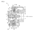
- FIG.1 is a partial cross-sectional view taken along a rotation axis, illustrating one example of an exhaust turbocharger with a variable nozzle mechanism (a variable displacement turbocharger).
- a turbine housing 3 of a thick-walled tubular shape is provided in an exhaust turbocharger 1, and a scroll 5 of a spiral shape is formed in an outer peripheral part on an upstream side of a turbine housing 3. Meanwhile, in an inner peripheral part on the upstream side of the turbine housing 3, a turbine rotor 7 of a radial flow type is provided.
- a turbine shaft 9 to which the turbine rotor 7 is attached has a rotation center which coincides with a rotation axis K in the drawing.
- the turbine shaft 9 is coaxial with a compressor (not shown). Further, the turbine shaft 9 is rotatably supported by a bearing housing 13 via a bearing 11.
- variable nozzle mechanism section 23 is a nozzle assembly which comprises a nozzle 19, a nozzle mount 21 and the like.
- a plurality of nozzles 19 is provided at equal intervals around the rotation axis K. Further, the nozzle 19 is positioned on an inner peripheral side of the scroll 5 in the radial direction of the turbine.
- the nozzle 19 includes a nozzle vane 19a and a nozzle shaft 19b.
- the nozzle shaft 19b is rotatably supported by a nozzle mount 21 fixed to the bearing housing 13.
- a plurality of supports for a plurality of the nozzle shafts 19b is provided at equal intervals.
- the nozzle vane 19 is disposed between the nozzle mount 21 and an annular nozzle plate 27.
- the annular nozzle plate 27 is connected to the nozzle mount 21 such that the nozzle plate 27 and the nozzle plate 21 face each other with a distance therebetween. The distance is provided in the axial direction of the turbine by nozzle supports 25.
- the nozzle plate 27 is fitted to a distal end side of an inner cylinder of the turbine housing 3.
- a stepped portion 29 is provided in the radial direction on the nozzle mount 21.
- a drive ring 31. of a disc shape is fitted to this stepped portion 29 concentrically with the rotation axis K to be rotatable.
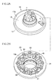
- On the drive ring 31, a plurality of gourd-shaped lever plates 33 is arranged in the circumferential direction and engages with the drive ring 31 as illustrated in FIG.2B .
- One end of this lever plate 33 is attached to the drive ring 31 and other end of this lever plate 33 is connected to an end of the nozzle shaft 19b.
- the nozzle shaft 19b penetrates an inner section of the nozzle mount 21 in the direction coinciding with the rotation axis K.
- the nozzle shaft 19b rotates, thereby rotating the nozzle vane 19a in accordance with the angle.
- an opening degree of the nozzle 19 can be adjusted by rotating the drive ring 31.
- twelve nozzle vanes 19a are arranged in the circumferential direction, and corresponding to these twelve nozzle vanes 19a, twelve lever plates 33 are arranged around the rotation axis K.
- a rivet 34 (see FIG.2B ) is disposed slightly lower (nearer to the center) than the stepped portion 29 of the nozzle mount 21 on which the drive ring 31 is provided. This rivet 34 is configured to retain the drive ring 31 by a flange head of the rivet 34 so that the drive ring 31 does not come off from the stepped portion 29.
- the nozzles 19 (19a, 19b), the nozzle mount 21, the nozzle plate 27, the drive ring 31 and the lever plates 33 that are described above are assembled to constitute the variable nozzle mechanism section 23. Further, on rear surface 15 of the bearing housing 13, the annular recess 17 is formed. In this recess 17, the link mechanism section (the link mechanism) 35 is provided through the rear surface 15.
- This link mechanism 35 is configured to convert reciprocal displacement from an actuator (not shown) for operating the variable nozzle mechanism 23 into rotational displacement so as to transmit rotational force to the variable nozzle mechanism 23 which is assembled to an inner section of the bearing housing 13.
- the link mechanism section 35 is constituted by an input lever 37 coupled to one end of the actuator, a coupling lever 39 connected to the other end of the input lever and disposed through the wall of the bearing housing 13, and an output lever 41 connected to the coupling lever 39 at one end.
- the output lever 41 is constituted by a two-fork portion 43 and a pin insertion groove 45 formed there between.
- a side surface of the two-fork portion 43 forms a smooth surface 47 where an end face of a pin 46 projecting from the side surface of the drive ring 31 contacts during assembly.
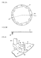
- FIG.3A is a front view of the drive ring 31 showing a front shape of the drive ring 31.
- oval fitting holes 49 are formed in the circumferential direction. To the oval fitting hole 49, one end of the lever plate 33 is attached.
- an engaging part 51 is formed by the two-fork portion 43, a pin insertion slot 45 formed on an inner side of the two-fork portion 43, and the pin 46.
- the engaging part 51 is configured to engage an output section of the link mechanism section 35 and an input section of the variable nozzle mechanism section 23 with each other using a pin 46.
- the output lever 41 is configured such that an end of the coupling lever 39 is connected to a root portion of the two-fork portion 43 and the pin insertion slot 45 formed between two forks of the two-fork portion 43 has a cut-out substantially oval shape.
- a short diameter part of the oval shape has such a width that the pin 46 is loosely fit therein.
- a tip portion of each of two forks of the two-fork portion 43 is rounded to form a corner R (Ra).
- an opening edge portion on the smooth surface 47 side of the two-fork portion 43 is rounded to form corner R (Rb) so as to facilitate insertion of the pin 46.
- An output lever 53 illustrated in FIG.5, FIG.6 , FIG.7A and FIG.7B is a modified example of the output lever 41 illustrated in FIG.4 .
- the output lever 53 includes a two-fork portion 55 and an insertion slot 54.
- the cross-sectional shape of the two-fork portion 55 has a substantially L-shape, width d of a smooth surface 57 of the substantially L-shape ( FIG.7 ) is formed wider than the output lever 41 of the linear shape as illustrated in FIG 4 the smooth surface 57 of the shape.
- the other configuration is similar to the FIG.4 .
- the larger width d on the smooth surface 57 side is secured.
- the operation of the exhaust turbocharger 1 with the variable nozzle mechanism having the above configuration is as follows.
- the exhaust gas from the engine enters the scroll 5, flows around along a swirl of the scroll 5 and flows through the nozzle vanes 19a.
- this exhaust gas passing between the nozzle vanes 19a flows into the turbine rotor 7 from the outer peripheral side, flows in the radial direction toward the center to perform expansion work to the turbine rotor 7 and then flows in the axial direction toward a gas outlet to be discharged to the outside.
- a vane angel of the nozzle vane 19a is set to an angle that achieves a prescribed flow rate of the exhaust gas flowing through the nozzle vanes 19a, and the vane angle is changed by an vane angle regulating part (not shown).
- the reciprocal displacement of the actuator corresponding to this vane angle is transmitted to the drive ring 31 to rotate the drive ring 31.
- the lever plate 33 rotates, thereby rotating the nozzle shaft 19b fixed to the other end of the lever plate 33.
- This rotation of the nozzle shaft 19b causes rotation of the nozzle vane 19a, thereby changing the vane angle.
- variable nozzle mechanism section 23 The assembly process of assembling the variable nozzle mechanism section 23 to the recess 17 formed on the rear surface 15 of the bearing housing 13 is now explained.
- the link mechanism section 35 is assembled to the bearing housing 13 side to prepare the bearing housing 13 assembled with this link mechanism section 35, and then the variable nozzle mechanism section 23 is assembled to the bearing housing 13 in such a manner that the variable nozzle mechanism section 23 overlaps the recess 17 op the bearing housing 13.
- the pin 46 constituting the engaging part 51 is roughly positioned so that the pin 46 is placed to the smooth surface 47 (57) of the two-fork portion 43 (55) of the output lever 41 (53).
- the tip portion of the pin 46 is moved along the smooth surface 47 (57) so as to position the tip position of the pin 46 at the pin insertion position while moving (see FIG.7B ).
- the peripheral edge portion of the oval opening on the smooth surface 47 (57) side is rounded into corner R (Rb) (approximately to R2 to R3) to facilitate insertion of the pin 46, and the pin 46 is moved along the smooth surface 47 (57) while pressing lightly.
- Rb corner R
- the pin 46 is pressed further to insert the pin 46 into the pin insertion slot 45 (54).
- the nozzle mount 21 fits the distal end of the recess 17 of the bearing housing 13, and the outer peripheral part of the nozzle mount 21 is sandwiched between the tip portion of the recess 17 and the stepped tip portion of the cylindrical opening part of the turbine housing 3 and fixed by a bolt 59.
- the nozzle plate 27 is fitted to the distal end side of the inner cylinder of the turbine housing 3.
- the pin 46 of the engaging part 51 is placed against the smooth surface 47 of the opposing output lever 41, and then position the pin 46 at the insertion slot 45 while moving the tip portion of the pin 46 along the smooth surface 47.
- the movement of the pin 46 along the smooth surface 47 stops, it can be easily determined that the pin 46 is at the insertion position. As a result, positioning of the pin 46 and the insertion position for the pin 46 is facilitated.
- pin 46 and the insertion slot 45 can be pushed relative to each other from the bearing housing 13 side or from the variable mechanism section 23 side.
- the engaging part 51 is arranged on an inner peripheral side of the recess 17 of the bearing housing 13, it is possible to reliably and easily perform the assembly even under poor visibility of the insertion position and the tip of the pin 46 due to the shadow of a longitudinal wall 17a of the recess 17.
- variable displacement turbocharger 1 As a result, there hardly occurs assembly defect and the quality stability of the variable displacement turbocharger 1 is improved.
- a second embodiment of the present invention is described with reference to FIG.8 .
- an engagement part 60 is configured such that the arrangement relation of the pin 46 and the pin insertion slot 45 (54) that constitute the engagement part 51 of the first embodiment is reversed.
- a pin 63 is formed at an end of an output lever 61, and an insertion slot 67 or an insertion hole is formed in a side wall surface of the outer peripheral side of the drive ring 65 at a position opposing the pin 63.
- This insertion slot 67 or insertion hole is formed by cutting and raising the side wall surface from the pin contact surface side to the opposite side. The corner of this cut and raised portion is rounded to form corner R (Rc) (approximately to R2 to R3).
- a smooth surface 69 is formed around the insertion slot 67 or the insertion hole of the pin 63 so as to guide a tip portion of the pin 63 to the insertion position.
- the side surface of the drive ring 65 around the insertion slot 67 or the insertion hole forms the smooth surface 69.
- the pin 63 of the engaging part 60 is placed against the smooth surface 69, and then the pin 63 is positioned at the insertion slot 67 while moving the tip portion of the pin 63 along the smooth surface 69.
- the pin 63 is at the insertion position.
- positioning of the pin 63 and the insertion position for the pin 63 is facilitated.
- the peripheral edge portion of the insertion slot or insertion hole for the pin is rounded to facilitate insertion of the pin. This is, however, not restrictive and the tip portion of the pin 46, 63 may be rounded as well.
- variable nozzle mechanism with a link mechanism for transmitting a drive from an external actuator when the variable nozzle mechanism assembly is formed and the variable nozzle mechanism assembly is assembled to a housing such as a bearing housing, and thus it is suitable for use in a variable displacement turbocharger.
Landscapes
- Engineering & Computer Science (AREA)
- Mechanical Engineering (AREA)
- General Engineering & Computer Science (AREA)
- Chemical & Material Sciences (AREA)
- Combustion & Propulsion (AREA)
- Physics & Mathematics (AREA)
- Geometry (AREA)
- Supercharger (AREA)
- Control Of Turbines (AREA)
Description
- The present invention relates to a variable displacement turbocharger equipped with a variable nozzle mechanism which is configured to vary a vane angle of a plurality of nozzle vanes, and in particular to a structure for assembling a variable nozzle mechanism assembly to a housing including a bearing housing as well as an assembly method of the variable nozzle mechanism.
- For relatively small exhaust turbochargers for use in an internal combustion engine for vehicles, etc., adopted is the configuration in which exhaust gas from the engine fills a scroll formed in a turbine housing, and passes through a plurality of nozzle vanes provided on an inner peripheral side of the scroll to act on a turbine rotor provided on an inner peripheral side of the plurality of nozzle vanes.
- Further, a variable displacement turbocharger equipped with a variable nozzle mechanism which is configured to vary an angle of a plurality of nozzle vanes is often used. Examples of this are described in
Patent Document 1 and Patent Document 2, for instance. - In this type of variable displacement turbocharger equipped with the variable nozzle mechanism, the variable nozzle mechanism is assembled and then the nozzle mechanism assembly is assembled to the bearing housing or the turbine housing.
- When assembling the nozzle mechanism to the bearing, it is necessary to connect a drive ring constituting the variable nozzle mechanism to a link mechanism for converting a drive force of reciprocal displacement from an actuator provided outside the turbine housing or the bearing housing into rotational displacement.
- A connection part is configured, as illustrated in
FIG.9 , such that asupport shaft 01 of the link mechanism penetrating a wall part of the bearing housing to be supported, alever 03 provided at a tip portion of thesupport shaft 01 on the housing inner section side, aconnection pin 05 provided at an end of thelever 03 and projecting in a direction perpendicular to thelever 03. Thisconnection pin 05 is fittingly inserted in anengagement protrusion 09 formed by cutting and raising a side surface of adrive ring 07 toward theconnection pin 05 side to be fitted therein, thedrive ring 07 constituting thevariable mechanism 06, so as to assemble the variable nozzle mechanism assembly to the bearing housing. As a result, the drive force of reciprocal displacement from the actuator is converted into the rotational drive force of thesupport shaft 01 by the link mechanism to rotate thewhole drive ring 07 through engagement between theconnection pin 05 and theengagement protrusion 09. - A front view of this
variable nozzle mechanism 06 is illustrated inFIG.10 . Theengagement protrusion 09 where theconnection pin 05 is inserted is formed in an outer peripheral side of the side surface of thedrive ring 07. Thevariable nozzle mechanism 06 is configured such that anozzle mount 010, alever plate 012, thedrive ring 07, etc. are assembled together to form the variable nozzle mechanism assembly. - This type of structure where the variable nozzle mechanism is assembled to the housing by engaging the pin part on the lever side with a engagement recess or hole on the drive ring side is described in Patent Document 1 (
JP 2008-215083 A JP 2009-150363 A - Described in
FIG.1 and the like ofPatent Document 1 is the configuration where reciprocal displacement from an actuator is transmitted to adrive ring 3 via alink 15 and a pin 14. - Further, described in
FIG.7 and the like of Patent Document 2 is the configuration wherein alink 15 is connected to an actuator providing a drive power for nozzle vanes 2, a crank pin 10s is connected to thelink 15, and the crank pin 10s engages with adrive ring 3 to rotate thedrive ring 3. -
- [Patent Document 1]
JP 2008-215083 A - [Patent Document 2]
JP 2009-150363 A - As illustrated in
FIG.9 , in the process of fitting theconnection pin 05 provided at the end of thelever 03 in a projecting manner into theengagement protrusion 09 on thedrive ring 07 side, as theengagement protrusion 09 is formed into a cut and erected shape, it takes time to insert a tip portion of theconnection pin 05 in between theengagement portions 09 disposed at both sides as illustrated inFIG.9 . Specifically, as both of the members are protruding members, it deteriorates efficiency of the assembling process. - Particularly, in the case where the
connection pin 05 or theengagement protrusion 09 is located in a rear of the inner section of the bearing housing, the turbine housing or the like, visibility is poor and it further deteriorates assembly workability. Further, if the variable nozzle mechanism is assembled to the housing without achieving suitable engagement, there is a possibility that it fails to exhibit sufficient performance due to assembly defect. - Also in
Patent Documents 1 and 2, it is necessary as in the foregoing description ofFIG 9 , to insert and engage the crank pin in the engagement slot or between a pair of engagement protrusions of the drive ring. However, neither of the documents discloses a structure considering the ease of fitting. Further, in the case where the insertion position is located in the inner section of the bearing housing, the turbine housing or the like where visibility is poor, there is a problem that it leads to deterioration in workability. - Accordingly, the present invention has been made in view of the above problems, and it is an object to achieve easy and reliable coupling operation of a variable nozzle mechanism with a link mechanism for transmitting a drive from an external actuator when the variable nozzle mechanism assembly is formed and the variable nozzle mechanism assembly is assembled to a housing such as a bearing housing.
- To achieve the above object, the present invention provides a variable displacement turbocharger comprising:
- a turbine housing into which exhaust gas from an internal combustion engine is introduced:
- a turbine rotor which is provided in the turbine housing and is configured to be rotated by the exhaust gas;
- a turbine shaft whose one end is inserted in the turbine housing, to said end the turbine rotor being attached;
- a bearing which is configured to support the turbine shaft;
- a bearing housing which houses the bearing and is formed with a cylindrical wall part protruding in an axial direction from an outer peripheral part;
- a variable nozzle mechanism which is assembled inside the cylindrical wall part of the bearing housing and is configured to regulate a flow of the exhaust gas to the turbine rotor;
- a link mechanism which is configured to convert reciprocal displacement from an actuator that operates the variable nozzle mechanism into rotational displacement and transmit the rotational displacement to an inner section of the bearing housing; and
- an engaging part which is configured to engage an output section of the link mechanism and an input section of the variable nozzle mechanism,
- wherein the engaging part is constituted by a pin insertion part which comprises a pin and a pin insertion hole or a pin insertion slot into which the pin is inserted, and a smooth surface is formed around an insertion position of the pin so as to guide a tip of the pin to the insertion position.
- According to this aspect of the present invention, the engaging part for engaging the output section of the link mechanism and the input section of the variable nozzle mechanism is constituted by the pin insertion part which comprises a pin and a pin insertion hole or a pin insertion slot into which the pin is inserted, and the smooth surface is formed around the insertion position of the pin so as to guide the tip of the pin to the insertion position. Therefore, when assembling and fixing the variable nozzle mechanism for adjusting the flow of exhaust gas to the turbine rotor to an inside of the cylindrical wall part of the bearing housing, positioning of the pin and the insertion position for the pin is facilitated.
- Especially, with the engaging part disposed inside the cylindrical wall part of the bearing housing, it is possible to reliably and easily perform the assembly even under poor visibility of the insertion position and the tip of the pin because of the shadow of the cylindrical wall part. As a result, there hardly occurs assembly defect and the quality stability of the variable displacement turbocharger is improved.
- It is preferable in the present invention that the pin projects from a side surface of the drive ring on an outer peripheral side of the drive ring constituting the variable nozzle mechanism, and the pin insertion part comprises a two-fork portion formed at an end of an output lever constituting the link mechanism and the insertion slot formed on an inner side of the two-fork portion, a side face of the two-fork portion forming the smooth surface.
- With this configuration, when assembling the variable nozzle mechanism to the inside of the cylindrical wall part of the bearing housing, the tip of the pin projecting from the side surface on the outer peripheral side of the drive ring constituting the variable nozzle mechanism is placed against the smooth surface formed on the side surface of the two-fork portion, and then the pin is moved along the smooth surface to the insertion position. This facilitates positioning of the pin and the insertion position.
- It is also preferable in the present invention that the pin projects from an end of an output lever constituting the link mechanism, and the pin insertion part comprises a slot or a hole formed in a side face of the drive ring on an outer peripheral side of the drive ring constituting the variable nozzle mechanism, the side face of the drive ring forming the smooth surface around the slot or the hole.
- With this configuration, when assembling the variable nozzle mechanism to the inside of the cylindrical wall part of the bearing housing, the tip of the pin projecting from the end of the output lever constituting the link mechanism is placed against the smooth surface formed around the slot or hole on the side surface of the outer peripheral side of the drive ring constituting the variable nozzle mechanism, and then the pin is moved along the smooth surface to the insertion position. This facilitates positioning of the pin and the insertion position.
- It is also preferable in the present invention that a peripheral edge portion of the pin insertion hole or the pin insertion slot of the pin insertion part is rounded to facilitate insertion of the pin.
- As the peripheral edge portion of the pin insertion hole or the pin insertion slot is rounded, the pin can be easily inserted in the insertion hole or the insertion slot and also the pin can be inserted reliably and easily when pushing the pin into the insertion hole by sliding the tip portion of the pin on the smooth surface to find the insertion position.
- The present invention provides an assemble method for assembling the above-described variable nozzle mechanism to the bearing housing, the method the steps of:
- preparing the bearing housing to which the link mechanism is assembled; and
- assembling the variable nozzle mechanism to the bearing housing,
- wherein the assembling step comprises the substeps of: placing the pin of the engaging part against the smooth surface; moving a tip portion of the pin along the smooth surface so as to position the tip portion in the insertion position; and then pushing the variable nozzle mechanism toward the bearing housing.
- According to this aspect of the present invention, the bearing housing to which the link mechanism is assembled is prepared first, and the variable nozzle mechanism is then assembled to the bearing housing. In the assembling step, the pin of the engaging part is placed against the smooth surface, a tip portion of the pin is moved along the smooth surface so as to position the tip portion in the insertion position, and then the variable nozzle mechanism is pushed toward the bearing housing. Therefore, the positioning of the pin and the insertion position for the pin is facilitated.
- Especially, as the engaging part is disposed inside the cylindrical wall part of the bearing housing, it is possible to reliably and easily perform the assembly even under poor visibility of the insertion position and the tip of the pin due to the shadow of the cylindrical wall part.
- According to the present invention, the engaging part for engaging the output section of the link mechanism and the input section of the variable nozzle mechanism is constituted by the pin insertion part which comprises a pin and a pin insertion hole or a pin insertion slot into which the pin is inserted, and the smooth surface is formed around the insertion position of the pin so as to guide the tip of the pin to the insertion position. Therefore, when assembling and fixing the variable nozzle mechanism for adjusting the flow of exhaust gas to the turbine rotor to an inside of the cylindrical wall part of the bearing housing, positioning of the pin and the insertion position for the pin is facilitated.
- Especially, as the engaging part is disposed inside the cylindrical wall part of the bearing housing, it is possible to reliably and easily perform the assembly even under poor visibility of the insertion position and the tip of the pin because of the shadow of the cylindrical wall part.
-
- [
FIG.1]FIG.1 is a cross-sectional view of a main part of a variable displacement turbocharger illustrating a first embodiment of the present invention. - [
FIG.2A] FIG.2A is an explanatory diagram for explaining an assembling state of a link mechanism section and a variable nozzle mechanism of the first embodiment and illustrates the link mechanism section. - [
FIG.2B] FIG.2B is an explanatory diagram for explaining an assembling state of the link mechanism section and the variable nozzle mechanism of the first embodiment and illustrates the variable mechanism section. - [
FIG.3A] FIG.3A is a front view of a drive ring according to the first embodiment. - [
FIG.3B] FIG.3B is a cross-sectional view taken along line C-C ofFIG.3A . - [
FIG.4] FIG.4 is an explanatory view illustrating engagement of the link mechanism section and the variable nozzle mechanism section according to the first embodiment. - [
FIG.5] FIG.5 is a first modified example of an engagement part ofFIG.4 . - [
FIG.6] FIG.6 is a second modified example of the engagement part ofFIG.4 . - [
FIG.7] FIG.7 is an explanatory view illustrating an assembling state at the engagement part ofFIG.4 . - [
FIG.8] FIG.8 is a cross-sectional explanatory view illustrating a second embodiment. - [
FIG.9] FIG.9 is an explanatory view of related art. - [
FIG.10] FIG.10 is an explanatory view of related art. - Embodiments of the present invention will now be described in detail with reference to the accompanying drawings.
- It is intended, however, that unless particularly specified, dimensions, materials, shapes, relative positions and the like of components described in the embodiments shall be interpreted as illustrative only and not limitative of the scope of the present invention.
- A first embodiment of the present invention is described with reference to
FIG.1 through FIG.7 . -
FIG.1 is a partial cross-sectional view taken along a rotation axis, illustrating one example of an exhaust turbocharger with a variable nozzle mechanism (a variable displacement turbocharger). - As illustrated in
FIG 1 , aturbine housing 3 of a thick-walled tubular shape is provided in anexhaust turbocharger 1, and ascroll 5 of a spiral shape is formed in an outer peripheral part on an upstream side of aturbine housing 3. Meanwhile, in an inner peripheral part on the upstream side of theturbine housing 3, aturbine rotor 7 of a radial flow type is provided. - A
turbine shaft 9 to which theturbine rotor 7 is attached has a rotation center which coincides with a rotation axis K in the drawing. Theturbine shaft 9 is coaxial with a compressor (not shown). Further, theturbine shaft 9 is rotatably supported by a bearinghousing 13 via abearing 11. - An annular recess (a cylindrical wall part) 17 is formed on a
rear surface 15 of the bearinghousing 13. In thisrecess 17, a variable nozzle mechanism section (a variable nozzle mechanism) 23 is accommodated. The variablenozzle mechanism section 23 is a nozzle assembly which comprises anozzle 19, anozzle mount 21 and the like. - A plurality of
nozzles 19 is provided at equal intervals around the rotation axis K. Further, thenozzle 19 is positioned on an inner peripheral side of thescroll 5 in the radial direction of the turbine. - In addition, the
nozzle 19 includes anozzle vane 19a and anozzle shaft 19b. Thenozzle shaft 19b is rotatably supported by anozzle mount 21 fixed to the bearinghousing 13. Around the rotation axis K, a plurality of supports for a plurality of thenozzle shafts 19b is provided at equal intervals. By this variablenozzle mechanism section 23, it is possible to vary the vane angle of thenozzle vanes 19a. - The
nozzle vane 19 is disposed between thenozzle mount 21 and anannular nozzle plate 27. Theannular nozzle plate 27 is connected to thenozzle mount 21 such that thenozzle plate 27 and thenozzle plate 21 face each other with a distance therebetween. The distance is provided in the axial direction of the turbine by nozzle supports 25. Thenozzle plate 27 is fitted to a distal end side of an inner cylinder of theturbine housing 3. - A stepped
portion 29 is provided in the radial direction on thenozzle mount 21. Adrive ring 31. of a disc shape is fitted to this steppedportion 29 concentrically with the rotation axis K to be rotatable. On thedrive ring 31, a plurality of gourd-shapedlever plates 33 is arranged in the circumferential direction and engages with thedrive ring 31 as illustrated inFIG.2B . One end of thislever plate 33 is attached to thedrive ring 31 and other end of thislever plate 33 is connected to an end of thenozzle shaft 19b. Thenozzle shaft 19b penetrates an inner section of thenozzle mount 21 in the direction coinciding with the rotation axis K. - In accordance with the rotation angle of the
drive ring 31 which rotates around the rotation axis K, thenozzle shaft 19b rotates, thereby rotating thenozzle vane 19a in accordance with the angle. Specifically, an opening degree of thenozzle 19 can be adjusted by rotating thedrive ring 31. Herein, twelvenozzle vanes 19a are arranged in the circumferential direction, and corresponding to these twelvenozzle vanes 19a, twelvelever plates 33 are arranged around the rotation axis K. - A rivet 34 (see
FIG.2B ) is disposed slightly lower (nearer to the center) than the steppedportion 29 of thenozzle mount 21 on which thedrive ring 31 is provided. Thisrivet 34 is configured to retain thedrive ring 31 by a flange head of therivet 34 so that thedrive ring 31 does not come off from the steppedportion 29. - The nozzles 19 (19a, 19b), the
nozzle mount 21, thenozzle plate 27, thedrive ring 31 and thelever plates 33 that are described above are assembled to constitute the variablenozzle mechanism section 23. Further, onrear surface 15 of the bearinghousing 13, theannular recess 17 is formed. In thisrecess 17, the link mechanism section (the link mechanism) 35 is provided through therear surface 15. - This
link mechanism 35 is configured to convert reciprocal displacement from an actuator (not shown) for operating thevariable nozzle mechanism 23 into rotational displacement so as to transmit rotational force to thevariable nozzle mechanism 23 which is assembled to an inner section of the bearinghousing 13. - The
link mechanism section 35 is constituted by aninput lever 37 coupled to one end of the actuator, acoupling lever 39 connected to the other end of the input lever and disposed through the wall of the bearinghousing 13, and anoutput lever 41 connected to thecoupling lever 39 at one end. - The
output lever 41, as illustrated inFIG.4 , is constituted by a two-fork portion 43 and apin insertion groove 45 formed there between. A side surface of the two-fork portion 43 forms asmooth surface 47 where an end face of apin 46 projecting from the side surface of thedrive ring 31 contacts during assembly.
FIG.3A is a front view of thedrive ring 31 showing a front shape of thedrive ring 31. In thedrive ring 31, oval fitting holes 49 are formed in the circumferential direction. To the ovalfitting hole 49, one end of thelever plate 33 is attached. - Further, an engaging
part 51 is formed by the two-fork portion 43, apin insertion slot 45 formed on an inner side of the two-fork portion 43, and thepin 46. The engagingpart 51 is configured to engage an output section of thelink mechanism section 35 and an input section of the variablenozzle mechanism section 23 with each other using apin 46. - The
output lever 41, as illustrated inFIG.4 , is configured such that an end of thecoupling lever 39 is connected to a root portion of the two-fork portion 43 and thepin insertion slot 45 formed between two forks of the two-fork portion 43 has a cut-out substantially oval shape. A short diameter part of the oval shape has such a width that thepin 46 is loosely fit therein. Further, a tip portion of each of two forks of the two-fork portion 43 is rounded to form a corner R (Ra). - By curved surface processing of this corner R (Ra), the engagement position between the two-
fork portion 43 and thepin 46 to avoid contact of the corner of the tip of the two-fork portion 43 to the inner peripheral wall surface of theannular recess 17 is positioned at the outer periphery of thedrive ring 31. Thus, stable rotation of thedrive ring 31 can be achieved with a small rotational force of theoutput lever 41. - Further, an opening edge portion on the
smooth surface 47 side of the two-fork portion 43 is rounded to form corner R (Rb) so as to facilitate insertion of thepin 46. - An
output lever 53 illustrated inFIG.5, FIG.6 ,FIG.7A and FIG.7B is a modified example of theoutput lever 41 illustrated inFIG.4 . - As illustrated in
FIG.5, FIG.6 ,FIG.7A and FIG.7B , theoutput lever 53 includes a two-fork portion 55 and aninsertion slot 54. The cross-sectional shape of the two-fork portion 55 has a substantially L-shape, width d of asmooth surface 57 of the substantially L-shape (FIG.7 ) is formed wider than theoutput lever 41 of the linear shape as illustrated inFIG 4 thesmooth surface 57 of the shape. - The other configuration is similar to the
FIG.4 . In this modified example, the larger width d on thesmooth surface 57 side is secured. Thus, it is possible to improve workability during assembly of thepin 46 due to the increased contact surface of the tip of thepin 46 and also achieve weight reduction of the overall weight of theoutput lever 53 by forming the section of the two-fork portion 55 contacting thepin 46 into substantially L-shape and reducing the thickness of other section compared to the lever ofFIG.4 . As a result, it is possible to obtain load reduction effect of the sliding portion and the stable rotational operation of theoutput lever 53 during the operation. - The operation of the
exhaust turbocharger 1 with the variable nozzle mechanism having the above configuration is as follows. The exhaust gas from the engine enters thescroll 5, flows around along a swirl of thescroll 5 and flows through thenozzle vanes 19a. Then, this exhaust gas passing between thenozzle vanes 19a flows into theturbine rotor 7 from the outer peripheral side, flows in the radial direction toward the center to perform expansion work to theturbine rotor 7 and then flows in the axial direction toward a gas outlet to be discharged to the outside. - To control displacement of the
exhaust turbocharger 1 with the variable nozzle mechanism, a vane angel of thenozzle vane 19a is set to an angle that achieves a prescribed flow rate of the exhaust gas flowing through thenozzle vanes 19a, and the vane angle is changed by an vane angle regulating part (not shown). The reciprocal displacement of the actuator corresponding to this vane angle is transmitted to thedrive ring 31 to rotate thedrive ring 31. By rotation of thedrive ring 31, thelever plate 33 rotates, thereby rotating thenozzle shaft 19b fixed to the other end of thelever plate 33. This rotation of thenozzle shaft 19b causes rotation of thenozzle vane 19a, thereby changing the vane angle. - The assembly process of assembling the variable
nozzle mechanism section 23 to therecess 17 formed on therear surface 15 of the bearinghousing 13 is now explained. - First, the
link mechanism section 35 is assembled to the bearinghousing 13 side to prepare the bearinghousing 13 assembled with thislink mechanism section 35, and then the variablenozzle mechanism section 23 is assembled to the bearinghousing 13 in such a manner that the variablenozzle mechanism section 23 overlaps therecess 17 op the bearinghousing 13. In this step, thepin 46 constituting the engagingpart 51 is roughly positioned so that thepin 46 is placed to the smooth surface 47 (57) of the two-fork portion 43 (55) of the output lever 41 (53). - Then, the tip portion of the
pin 46 is moved along the smooth surface 47 (57) so as to position the tip position of thepin 46 at the pin insertion position while moving (seeFIG.7B ). - The peripheral edge portion of the oval opening on the smooth surface 47 (57) side is rounded into corner R (Rb) (approximately to R2 to R3) to facilitate insertion of the
pin 46, and thepin 46 is moved along the smooth surface 47 (57) while pressing lightly. Thus, as movement of thepin 46 along thesmooth surface 47 stops at the insertion position, it can be determined that the pin is at the insertion position. - Then, the
pin 46 is pressed further to insert thepin 46 into the pin insertion slot 45 (54). - Next, it is positioned so that the outer peripheral part of the
nozzle mount 21 fits the distal end of therecess 17 of the bearinghousing 13, and the outer peripheral part of thenozzle mount 21 is sandwiched between the tip portion of therecess 17 and the stepped tip portion of the cylindrical opening part of theturbine housing 3 and fixed by a bolt 59. When sandwiching the outer peripheral part of thenozzle mount 21 between the bearinghousing 13 and theturbine housing 3, thenozzle plate 27 is fitted to the distal end side of the inner cylinder of theturbine housing 3. - According to the above assembly method, when assembling the variable
nozzle mechanism section 23 to the bearinghousing 13, thepin 46 of theengaging part 51 is placed against thesmooth surface 47 of the opposingoutput lever 41, and then position thepin 46 at theinsertion slot 45 while moving the tip portion of thepin 46 along thesmooth surface 47. When the movement of thepin 46 along thesmooth surface 47 stops, it can be easily determined that thepin 46 is at the insertion position. As a result, positioning of thepin 46 and the insertion position for thepin 46 is facilitated. - Further, the
pin 46 and theinsertion slot 45 can be pushed relative to each other from the bearinghousing 13 side or from thevariable mechanism section 23 side. - As the engaging
part 51 is arranged on an inner peripheral side of therecess 17 of the bearinghousing 13, it is possible to reliably and easily perform the assembly even under poor visibility of the insertion position and the tip of thepin 46 due to the shadow of alongitudinal wall 17a of therecess 17. - As a result, there hardly occurs assembly defect and the quality stability of the
variable displacement turbocharger 1 is improved. - A second embodiment of the present invention is described with reference to
FIG.8 . - In the second embodiment, an
engagement part 60 is configured such that the arrangement relation of thepin 46 and the pin insertion slot 45 (54) that constitute theengagement part 51 of the first embodiment is reversed. - As illustrated in
FIG 8 , apin 63 is formed at an end of anoutput lever 61, and aninsertion slot 67 or an insertion hole is formed in a side wall surface of the outer peripheral side of thedrive ring 65 at a position opposing thepin 63. Thisinsertion slot 67 or insertion hole is formed by cutting and raising the side wall surface from the pin contact surface side to the opposite side. The corner of this cut and raised portion is rounded to form corner R (Rc) (approximately to R2 to R3). - Further, a
smooth surface 69 is formed around theinsertion slot 67 or the insertion hole of thepin 63 so as to guide a tip portion of thepin 63 to the insertion position. Specifically, the side surface of thedrive ring 65 around theinsertion slot 67 or the insertion hole forms thesmooth surface 69. - In the second embodiment, as in the first embodiment, when assembling the variable
nozzle mechanism section 23 to the bearinghousing 13, thepin 63 of theengaging part 60 is placed against thesmooth surface 69, and then thepin 63 is positioned at theinsertion slot 67 while moving the tip portion of thepin 63 along thesmooth surface 69. Thus, when the movement of thepin 63 along thesmooth surface 69 stops, it can be easily determined that thepin 63 is at the insertion position. As a result, positioning of thepin 63 and the insertion position for thepin 63 is facilitated. - In the above first embodiment and second embodiment, the peripheral edge portion of the insertion slot or insertion hole for the pin is rounded to facilitate insertion of the pin. This is, however, not restrictive and the tip portion of the
pin - According to the present invention, it is possible to achieve easy and reliable coupling operation of a variable nozzle mechanism with a link mechanism for transmitting a drive from an external actuator when the variable nozzle mechanism assembly is formed and the variable nozzle mechanism assembly is assembled to a housing such as a bearing housing, and thus it is suitable for use in a variable displacement turbocharger.
Claims (5)
- A variable displacement turbocharger comprising:a turbine housing into which exhaust gas from an internal combustion engine is introduced:a turbine rotor which is provided in the turbine housing and is configured to be rotated by the exhaust gas;a turbine shaft whose one end is inserted in the turbine housing, to said end the turbine rotor being attached;a bearing which is configured to support the turbine shaft;a bearing housing which houses the bearing and is formed with a cylindrical wall part protruding in an axial direction from an outer peripheral part;a variable nozzle mechanism which is assembled inside the cylindrical wall part of the bearing housing and is configured to regulate a flow of the exhaust gas to the turbine rotor;a link mechanism which is configured to convert reciprocal displacement from an actuator that operates the variable nozzle mechanism into rotational displacement and transmit the rotational displacement to an inner section of the bearing housing; andan engaging part which is configured to engage an output section of the link mechanism and an input section of the variable nozzle mechanism,wherein the engaging part is constituted by a pin insertion part which comprises a pin and a pin insertion hole or a pin insertion slot into which the pin is inserted, and a smooth surface is formed around an insertion position of the pin so as to guide a tip of the pin to the insertion position.
- The variable displacement turbocharger, according to claim 1,
wherein the pin projects from a side surface of the drive ring on an outer peripheral side of the drive ring constituting the variable nozzle mechanism, and the pin insertion part comprises a two-fork portion formed at an end of an output lever constituting the link mechanism and the insertion slot formed on an inner side of the two-fork portion, a side face of the two-fork portion forming the smooth surface. - The variable displacement turbocharger, according to claim 1,
wherein the pin projects from an end of an output lever constituting the link mechanism, and the pin insertion part comprises a slot or a hole formed in a side face of the drive ring on an outer peripheral side of the drive ring constituting the variable nozzle mechanism, the side face of the drive ring forming the smooth surface around the slot or the hole. - The variable displacement turbocharger, according to claim 2 or 3,
wherein a peripheral edge portion of the pin insertion hole or the pin insertion slot of the pin insertion part is rounded to facilitate insertion of the pin. - An assemble method for assembling the variable nozzle mechanism of any one of claims 1 to 4 to the bearing housing, the method comprising the steps of:preparing the bearing housing to which the link mechanism is assembled; andassembling the variable nozzle mechanism to the bearing housing,wherein the assembling step comprises the substeps of:placing the pin of the engaging part against the smooth surface;moving a tip portion of the pin along the smooth surface so as to position the tip portion in the insertion position; and thenpushing the variable nozzle mechanism toward the bearing housing.
Applications Claiming Priority (2)
| Application Number | Priority Date | Filing Date | Title |
|---|---|---|---|
| JP2011213558A JP5134717B1 (en) | 2011-09-28 | 2011-09-28 | Variable capacity turbocharger and variable nozzle mechanism assembly method |
| PCT/JP2012/072888 WO2013047154A1 (en) | 2011-09-28 | 2012-09-07 | Variable capacity-type turbocharger and assembly method for variable nozzle mechanism |
Publications (3)
| Publication Number | Publication Date |
|---|---|
| EP2762701A1 true EP2762701A1 (en) | 2014-08-06 |
| EP2762701A4 EP2762701A4 (en) | 2015-06-03 |
| EP2762701B1 EP2762701B1 (en) | 2020-03-04 |
Family
ID=47693082
Family Applications (1)
| Application Number | Title | Priority Date | Filing Date |
|---|---|---|---|
| EP12837441.0A Active EP2762701B1 (en) | 2011-09-28 | 2012-09-07 | Variable displacement turbocharger and corresponding method for assembling the variable nozzle mechanism with which it is equipped |
Country Status (5)
| Country | Link |
|---|---|
| US (1) | US9790949B2 (en) |
| EP (1) | EP2762701B1 (en) |
| JP (1) | JP5134717B1 (en) |
| CN (1) | CN103688036B (en) |
| WO (1) | WO2013047154A1 (en) |
Families Citing this family (19)
| Publication number | Priority date | Publication date | Assignee | Title |
|---|---|---|---|---|
| IN2014DN07030A (en) * | 2012-02-02 | 2015-04-10 | Borgwarner Inc | |
| JP6178917B2 (en) * | 2013-08-19 | 2017-08-09 | ボーグワーナー インコーポレーテッド | Exhaust gas turbocharger |
| US9429033B2 (en) * | 2013-11-08 | 2016-08-30 | Honeywell International Inc. | Drive arrangement for a unison ring of a variable-vane assembly |
| CN103953585B (en) * | 2014-05-21 | 2016-11-09 | 无锡杰尔压缩机有限公司 | Fork type torque amplification device |
| EP3234310B1 (en) * | 2014-12-19 | 2020-08-26 | Volvo Truck Corporation | A turbocharger, and a method for manufacturing a turbocharger |
| US10851706B2 (en) | 2015-02-24 | 2020-12-01 | Mitsubishi Heavy Industries Engine & Turbocharger, Ltd. | Variable nozzle mechanism and variable displacement type exhaust turbocharger |
| DE102015213321A1 (en) * | 2015-07-16 | 2017-01-19 | Bosch Mahle Turbo Systems Gmbh & Co. Kg | Variable turbine or compressor geometry for an exhaust gas turbocharger |
| US10227887B2 (en) * | 2015-10-07 | 2019-03-12 | Hanwha Power Systems Co., Ltd. | Fluid machine with variable vanes |
| EP3421753B1 (en) * | 2016-03-28 | 2020-08-26 | Mitsubishi Heavy Industries Engine & Turbocharger, Ltd. | Variable geometry turbocharger |
| US10393009B2 (en) * | 2016-04-19 | 2019-08-27 | Garrett Transportation I Inc. | Adjustable-trim centrifugal compressor for a turbocharger |
| DE112017004220T5 (en) * | 2016-08-24 | 2019-05-09 | Ihi Corporation | Turbocharger with variable displacement |
| CN108979736B (en) * | 2018-06-22 | 2021-08-17 | 苏州诺迅汽车零部件有限公司 | Variable cross-section booster |
| US11092167B2 (en) * | 2018-08-28 | 2021-08-17 | Pratt & Whitney Canada Corp. | Variable vane actuating system |
| US11092032B2 (en) * | 2018-08-28 | 2021-08-17 | Pratt & Whitney Canada Corp. | Variable vane actuating system |
| DE112021001344T5 (en) | 2020-06-02 | 2022-12-29 | Ihi Corporation | charging device |
| US11371380B2 (en) | 2020-12-01 | 2022-06-28 | Pratt & Whitney Canada Corp. | Variable guide vane assembly and vane arms therefor |
| US11319870B1 (en) * | 2021-04-13 | 2022-05-03 | Eyal Ezra | Turbocharger control valve for retaining back pressure and maintaining boost pressure |
| CN117773530B (en) * | 2024-02-23 | 2024-05-10 | 江苏奕雯杰燃油喷射科技有限公司 | Precise assembly device for fuel nozzle |
| CN119353247B (en) * | 2024-09-12 | 2026-01-09 | 中国船舶集团有限公司第七〇三研究所 | A widely applicable device and method for measuring the angular displacement of rotatable guide vanes in gas turbine compressors. |
Family Cites Families (15)
| Publication number | Priority date | Publication date | Assignee | Title |
|---|---|---|---|---|
| US4741666A (en) * | 1985-12-23 | 1988-05-03 | Ishikawajima-Harima Jukogyo Kabushiki Kaisha | Variable displacement turbocharger |
| JP2000027654A (en) * | 1998-07-09 | 2000-01-25 | Toyota Motor Corp | Negative pressure device |
| JP3686311B2 (en) * | 2000-06-28 | 2005-08-24 | 三菱重工業株式会社 | Variable turbocharger |
| JP2004270472A (en) * | 2003-03-06 | 2004-09-30 | Isuzu Motors Ltd | Variable capacity turbocharger |
| JP4086029B2 (en) * | 2004-10-05 | 2008-05-14 | いすゞ自動車株式会社 | Engine control apparatus and control method |
| JP2006207526A (en) | 2005-01-31 | 2006-08-10 | Mitsubishi Heavy Ind Ltd | Variable displacement type exhaust turbocharger and method for manufacturing variable nozzle mechanism structural member |
| JP4234107B2 (en) * | 2005-02-10 | 2009-03-04 | 三菱重工業株式会社 | Variable displacement exhaust turbocharger and variable nozzle mechanism component manufacturing method |
| JP4545068B2 (en) | 2005-08-25 | 2010-09-15 | 三菱重工業株式会社 | Variable displacement exhaust turbocharger and variable nozzle mechanism component manufacturing method |
| JP2008215083A (en) * | 2007-02-28 | 2008-09-18 | Mitsubishi Heavy Ind Ltd | Mounting structure for variable nozzle mechanism in variable geometry exhaust turbocharger |
| JP4885118B2 (en) * | 2007-12-21 | 2012-02-29 | 三菱重工業株式会社 | Variable displacement exhaust turbocharger with variable nozzle mechanism |
| JP2009174363A (en) * | 2008-01-23 | 2009-08-06 | Toyota Motor Corp | Control device for internal combustion engine with variable capacity supercharger |
| JP2010180864A (en) | 2009-02-09 | 2010-08-19 | Toyota Motor Corp | Variable nozzle unit |
| JP5010631B2 (en) | 2009-02-27 | 2012-08-29 | 三菱重工業株式会社 | Variable displacement exhaust turbocharger |
| JP2010216281A (en) * | 2009-03-13 | 2010-09-30 | Akita Fine Blanking:Kk | Exhaust guide assembly in vgs type turbocharger |
| JP4741709B1 (en) * | 2010-07-09 | 2011-08-10 | 株式会社アキタファインブランキング | Exhaust guide assembly for VGS type turbocharger |
-
2011
- 2011-09-28 JP JP2011213558A patent/JP5134717B1/en active Active
-
2012
- 2012-09-07 US US14/232,563 patent/US9790949B2/en active Active
- 2012-09-07 WO PCT/JP2012/072888 patent/WO2013047154A1/en not_active Ceased
- 2012-09-07 EP EP12837441.0A patent/EP2762701B1/en active Active
- 2012-09-07 CN CN201280035925.9A patent/CN103688036B/en active Active
Also Published As
| Publication number | Publication date |
|---|---|
| CN103688036A (en) | 2014-03-26 |
| JP5134717B1 (en) | 2013-01-30 |
| US9790949B2 (en) | 2017-10-17 |
| EP2762701A4 (en) | 2015-06-03 |
| US20140161595A1 (en) | 2014-06-12 |
| EP2762701B1 (en) | 2020-03-04 |
| WO2013047154A1 (en) | 2013-04-04 |
| CN103688036B (en) | 2019-01-22 |
| JP2013072403A (en) | 2013-04-22 |
Similar Documents
| Publication | Publication Date | Title |
|---|---|---|
| US9790949B2 (en) | Variable displacement turbocharger and assembly method of variable nozzle mechanism | |
| US7771161B2 (en) | Adjustable guide device | |
| KR100382090B1 (en) | Variable nozzle mechanism of variable capacity turbine | |
| US9664060B2 (en) | Variable nozzle unit and variable geometry system turbocharger | |
| US7351042B2 (en) | Structure of scroll of variable-throat exhaust turbocharger and method for manufacturing the turbocharger | |
| JP3735262B2 (en) | Variable nozzle mechanism for variable capacity turbine and manufacturing method thereof | |
| US10641125B2 (en) | Nozzle drive mechanism, turbocharger, and variable-capacity turbocharger | |
| EP1965039A2 (en) | Mounting structure for variable nozzle mechanism in variable-throat exhaust turbocharger | |
| CN101542075A (en) | Variable-vane assembly with fixed axial-radial guide for unison ring and fixed single radial guide | |
| US9784119B2 (en) | Opening degree regulating structure for variable nozzle mechanism and variable displacement turbocharger | |
| EP1234951A2 (en) | Adjustable nozzle vane mechanism | |
| CN101415951A (en) | Preswirl guide device | |
| JP5989905B2 (en) | Variable guide mechanism for turbine, turbine for exhaust gas turbocharger, and exhaust gas turbocharger | |
| WO2017203962A1 (en) | Supercharger | |
| JP6806224B2 (en) | Variable capacity turbocharger | |
| US10233828B2 (en) | Variable nozzle unit and variable geometry system turbocharger | |
| JP2013019304A (en) | Variable guide vane device of compressor, method of assembling the same, and supercharger | |
| JP2011043119A (en) | Nozzle vane and turbocharger | |
| US9091179B2 (en) | Variable geometry turbine and assembly thereof | |
| JP2013217305A (en) | Connection structure, variable nozzle unit, and variable displacement supercharger | |
| WO2024201963A1 (en) | Variable displacement turbocharger and assembling method for variable displacement turbocharger | |
| CN116428220A (en) | Stator blade, stator device and compressor | |
| CN115522992A (en) | Turboexpander | |
| JP2010249042A (en) | Stationary blade angle variable device and axial flow compressor |
Legal Events
| Date | Code | Title | Description |
|---|---|---|---|
| PUAI | Public reference made under article 153(3) epc to a published international application that has entered the european phase |
Free format text: ORIGINAL CODE: 0009012 |
|
| 17P | Request for examination filed |
Effective date: 20140110 |
|
| AK | Designated contracting states |
Kind code of ref document: A1 Designated state(s): AL AT BE BG CH CY CZ DE DK EE ES FI FR GB GR HR HU IE IS IT LI LT LU LV MC MK MT NL NO PL PT RO RS SE SI SK SM TR |
|
| DAX | Request for extension of the european patent (deleted) | ||
| RA4 | Supplementary search report drawn up and despatched (corrected) |
Effective date: 20150506 |
|
| RIC1 | Information provided on ipc code assigned before grant |
Ipc: F01D 17/16 20060101ALI20150428BHEP Ipc: F02B 37/24 20060101AFI20150428BHEP |
|
| RAP1 | Party data changed (applicant data changed or rights of an application transferred) |
Owner name: MITSUBISHI HEAVY INDUSTRIES ENGINE & TURBOCHARGER, |
|
| GRAP | Despatch of communication of intention to grant a patent |
Free format text: ORIGINAL CODE: EPIDOSNIGR1 |
|
| STAA | Information on the status of an ep patent application or granted ep patent |
Free format text: STATUS: GRANT OF PATENT IS INTENDED |
|
| INTG | Intention to grant announced |
Effective date: 20190924 |
|
| GRAS | Grant fee paid |
Free format text: ORIGINAL CODE: EPIDOSNIGR3 |
|
| GRAA | (expected) grant |
Free format text: ORIGINAL CODE: 0009210 |
|
| STAA | Information on the status of an ep patent application or granted ep patent |
Free format text: STATUS: THE PATENT HAS BEEN GRANTED |
|
| AK | Designated contracting states |
Kind code of ref document: B1 Designated state(s): AL AT BE BG CH CY CZ DE DK EE ES FI FR GB GR HR HU IE IS IT LI LT LU LV MC MK MT NL NO PL PT RO RS SE SI SK SM TR |
|
| REG | Reference to a national code |
Ref country code: GB Ref legal event code: FG4D |
|
| REG | Reference to a national code |
Ref country code: CH Ref legal event code: EP |
|
| REG | Reference to a national code |
Ref country code: AT Ref legal event code: REF Ref document number: 1240623 Country of ref document: AT Kind code of ref document: T Effective date: 20200315 |
|
| REG | Reference to a national code |
Ref country code: DE Ref legal event code: R096 Ref document number: 602012068282 Country of ref document: DE |
|
| REG | Reference to a national code |
Ref country code: IE Ref legal event code: FG4D |
|
| REG | Reference to a national code |
Ref country code: NL Ref legal event code: FP |
|
| PG25 | Lapsed in a contracting state [announced via postgrant information from national office to epo] |
Ref country code: NO Free format text: LAPSE BECAUSE OF FAILURE TO SUBMIT A TRANSLATION OF THE DESCRIPTION OR TO PAY THE FEE WITHIN THE PRESCRIBED TIME-LIMIT Effective date: 20200604 Ref country code: FI Free format text: LAPSE BECAUSE OF FAILURE TO SUBMIT A TRANSLATION OF THE DESCRIPTION OR TO PAY THE FEE WITHIN THE PRESCRIBED TIME-LIMIT Effective date: 20200304 Ref country code: RS Free format text: LAPSE BECAUSE OF FAILURE TO SUBMIT A TRANSLATION OF THE DESCRIPTION OR TO PAY THE FEE WITHIN THE PRESCRIBED TIME-LIMIT Effective date: 20200304 |
|
| PG25 | Lapsed in a contracting state [announced via postgrant information from national office to epo] |
Ref country code: BG Free format text: LAPSE BECAUSE OF FAILURE TO SUBMIT A TRANSLATION OF THE DESCRIPTION OR TO PAY THE FEE WITHIN THE PRESCRIBED TIME-LIMIT Effective date: 20200604 Ref country code: HR Free format text: LAPSE BECAUSE OF FAILURE TO SUBMIT A TRANSLATION OF THE DESCRIPTION OR TO PAY THE FEE WITHIN THE PRESCRIBED TIME-LIMIT Effective date: 20200304 Ref country code: GR Free format text: LAPSE BECAUSE OF FAILURE TO SUBMIT A TRANSLATION OF THE DESCRIPTION OR TO PAY THE FEE WITHIN THE PRESCRIBED TIME-LIMIT Effective date: 20200605 Ref country code: LV Free format text: LAPSE BECAUSE OF FAILURE TO SUBMIT A TRANSLATION OF THE DESCRIPTION OR TO PAY THE FEE WITHIN THE PRESCRIBED TIME-LIMIT Effective date: 20200304 Ref country code: SE Free format text: LAPSE BECAUSE OF FAILURE TO SUBMIT A TRANSLATION OF THE DESCRIPTION OR TO PAY THE FEE WITHIN THE PRESCRIBED TIME-LIMIT Effective date: 20200304 |
|
| REG | Reference to a national code |
Ref country code: LT Ref legal event code: MG4D |
|
| PG25 | Lapsed in a contracting state [announced via postgrant information from national office to epo] |
Ref country code: ES Free format text: LAPSE BECAUSE OF FAILURE TO SUBMIT A TRANSLATION OF THE DESCRIPTION OR TO PAY THE FEE WITHIN THE PRESCRIBED TIME-LIMIT Effective date: 20200304 Ref country code: LT Free format text: LAPSE BECAUSE OF FAILURE TO SUBMIT A TRANSLATION OF THE DESCRIPTION OR TO PAY THE FEE WITHIN THE PRESCRIBED TIME-LIMIT Effective date: 20200304 Ref country code: SK Free format text: LAPSE BECAUSE OF FAILURE TO SUBMIT A TRANSLATION OF THE DESCRIPTION OR TO PAY THE FEE WITHIN THE PRESCRIBED TIME-LIMIT Effective date: 20200304 Ref country code: IS Free format text: LAPSE BECAUSE OF FAILURE TO SUBMIT A TRANSLATION OF THE DESCRIPTION OR TO PAY THE FEE WITHIN THE PRESCRIBED TIME-LIMIT Effective date: 20200704 Ref country code: CZ Free format text: LAPSE BECAUSE OF FAILURE TO SUBMIT A TRANSLATION OF THE DESCRIPTION OR TO PAY THE FEE WITHIN THE PRESCRIBED TIME-LIMIT Effective date: 20200304 Ref country code: RO Free format text: LAPSE BECAUSE OF FAILURE TO SUBMIT A TRANSLATION OF THE DESCRIPTION OR TO PAY THE FEE WITHIN THE PRESCRIBED TIME-LIMIT Effective date: 20200304 Ref country code: EE Free format text: LAPSE BECAUSE OF FAILURE TO SUBMIT A TRANSLATION OF THE DESCRIPTION OR TO PAY THE FEE WITHIN THE PRESCRIBED TIME-LIMIT Effective date: 20200304 Ref country code: PT Free format text: LAPSE BECAUSE OF FAILURE TO SUBMIT A TRANSLATION OF THE DESCRIPTION OR TO PAY THE FEE WITHIN THE PRESCRIBED TIME-LIMIT Effective date: 20200729 Ref country code: SM Free format text: LAPSE BECAUSE OF FAILURE TO SUBMIT A TRANSLATION OF THE DESCRIPTION OR TO PAY THE FEE WITHIN THE PRESCRIBED TIME-LIMIT Effective date: 20200304 |
|
| PGFP | Annual fee paid to national office [announced via postgrant information from national office to epo] |
Ref country code: FR Payment date: 20200921 Year of fee payment: 9 Ref country code: GB Payment date: 20200923 Year of fee payment: 9 Ref country code: NL Payment date: 20200921 Year of fee payment: 9 |
|
| REG | Reference to a national code |
Ref country code: AT Ref legal event code: MK05 Ref document number: 1240623 Country of ref document: AT Kind code of ref document: T Effective date: 20200304 |
|
| REG | Reference to a national code |
Ref country code: DE Ref legal event code: R097 Ref document number: 602012068282 Country of ref document: DE |
|
| PLBE | No opposition filed within time limit |
Free format text: ORIGINAL CODE: 0009261 |
|
| STAA | Information on the status of an ep patent application or granted ep patent |
Free format text: STATUS: NO OPPOSITION FILED WITHIN TIME LIMIT |
|
| PG25 | Lapsed in a contracting state [announced via postgrant information from national office to epo] |
Ref country code: DK Free format text: LAPSE BECAUSE OF FAILURE TO SUBMIT A TRANSLATION OF THE DESCRIPTION OR TO PAY THE FEE WITHIN THE PRESCRIBED TIME-LIMIT Effective date: 20200304 Ref country code: IT Free format text: LAPSE BECAUSE OF FAILURE TO SUBMIT A TRANSLATION OF THE DESCRIPTION OR TO PAY THE FEE WITHIN THE PRESCRIBED TIME-LIMIT Effective date: 20200304 Ref country code: AT Free format text: LAPSE BECAUSE OF FAILURE TO SUBMIT A TRANSLATION OF THE DESCRIPTION OR TO PAY THE FEE WITHIN THE PRESCRIBED TIME-LIMIT Effective date: 20200304 |
|
| 26N | No opposition filed |
Effective date: 20201207 |
|
| PG25 | Lapsed in a contracting state [announced via postgrant information from national office to epo] |
Ref country code: SI Free format text: LAPSE BECAUSE OF FAILURE TO SUBMIT A TRANSLATION OF THE DESCRIPTION OR TO PAY THE FEE WITHIN THE PRESCRIBED TIME-LIMIT Effective date: 20200304 Ref country code: PL Free format text: LAPSE BECAUSE OF FAILURE TO SUBMIT A TRANSLATION OF THE DESCRIPTION OR TO PAY THE FEE WITHIN THE PRESCRIBED TIME-LIMIT Effective date: 20200304 |
|
| PG25 | Lapsed in a contracting state [announced via postgrant information from national office to epo] |
Ref country code: MC Free format text: LAPSE BECAUSE OF FAILURE TO SUBMIT A TRANSLATION OF THE DESCRIPTION OR TO PAY THE FEE WITHIN THE PRESCRIBED TIME-LIMIT Effective date: 20200304 |
|
| REG | Reference to a national code |
Ref country code: CH Ref legal event code: PL |
|
| REG | Reference to a national code |
Ref country code: BE Ref legal event code: MM Effective date: 20200930 |
|
| PG25 | Lapsed in a contracting state [announced via postgrant information from national office to epo] |
Ref country code: LU Free format text: LAPSE BECAUSE OF NON-PAYMENT OF DUE FEES Effective date: 20200907 |
|
| PG25 | Lapsed in a contracting state [announced via postgrant information from national office to epo] |
Ref country code: LI Free format text: LAPSE BECAUSE OF NON-PAYMENT OF DUE FEES Effective date: 20200930 Ref country code: IE Free format text: LAPSE BECAUSE OF NON-PAYMENT OF DUE FEES Effective date: 20200907 Ref country code: BE Free format text: LAPSE BECAUSE OF NON-PAYMENT OF DUE FEES Effective date: 20200930 Ref country code: CH Free format text: LAPSE BECAUSE OF NON-PAYMENT OF DUE FEES Effective date: 20200930 |
|
| REG | Reference to a national code |
Ref country code: NL Ref legal event code: MM Effective date: 20211001 |
|
| GBPC | Gb: european patent ceased through non-payment of renewal fee |
Effective date: 20210907 |
|
| PG25 | Lapsed in a contracting state [announced via postgrant information from national office to epo] |
Ref country code: TR Free format text: LAPSE BECAUSE OF FAILURE TO SUBMIT A TRANSLATION OF THE DESCRIPTION OR TO PAY THE FEE WITHIN THE PRESCRIBED TIME-LIMIT Effective date: 20200304 Ref country code: MT Free format text: LAPSE BECAUSE OF FAILURE TO SUBMIT A TRANSLATION OF THE DESCRIPTION OR TO PAY THE FEE WITHIN THE PRESCRIBED TIME-LIMIT Effective date: 20200304 Ref country code: CY Free format text: LAPSE BECAUSE OF FAILURE TO SUBMIT A TRANSLATION OF THE DESCRIPTION OR TO PAY THE FEE WITHIN THE PRESCRIBED TIME-LIMIT Effective date: 20200304 |
|
| PG25 | Lapsed in a contracting state [announced via postgrant information from national office to epo] |
Ref country code: NL Free format text: LAPSE BECAUSE OF NON-PAYMENT OF DUE FEES Effective date: 20211001 Ref country code: MK Free format text: LAPSE BECAUSE OF FAILURE TO SUBMIT A TRANSLATION OF THE DESCRIPTION OR TO PAY THE FEE WITHIN THE PRESCRIBED TIME-LIMIT Effective date: 20200304 Ref country code: AL Free format text: LAPSE BECAUSE OF FAILURE TO SUBMIT A TRANSLATION OF THE DESCRIPTION OR TO PAY THE FEE WITHIN THE PRESCRIBED TIME-LIMIT Effective date: 20200304 |
|
| PG25 | Lapsed in a contracting state [announced via postgrant information from national office to epo] |
Ref country code: GB Free format text: LAPSE BECAUSE OF NON-PAYMENT OF DUE FEES Effective date: 20210907 Ref country code: FR Free format text: LAPSE BECAUSE OF NON-PAYMENT OF DUE FEES Effective date: 20210930 |
|
| PGFP | Annual fee paid to national office [announced via postgrant information from national office to epo] |
Ref country code: DE Payment date: 20250730 Year of fee payment: 14 |