EP2762691A1 - ORC-Anlage mit verbesserter Wärmebereitstellung - Google Patents
ORC-Anlage mit verbesserter Wärmebereitstellung Download PDFInfo
- Publication number
- EP2762691A1 EP2762691A1 EP13195007.3A EP13195007A EP2762691A1 EP 2762691 A1 EP2762691 A1 EP 2762691A1 EP 13195007 A EP13195007 A EP 13195007A EP 2762691 A1 EP2762691 A1 EP 2762691A1
- Authority
- EP
- European Patent Office
- Prior art keywords
- fluid
- turbine
- condenser
- evaporator
- working medium
- Prior art date
- Legal status (The legal status is an assumption and is not a legal conclusion. Google has not performed a legal analysis and makes no representation as to the accuracy of the status listed.)
- Granted
Links
Images

Classifications
-
- F—MECHANICAL ENGINEERING; LIGHTING; HEATING; WEAPONS; BLASTING
- F01—MACHINES OR ENGINES IN GENERAL; ENGINE PLANTS IN GENERAL; STEAM ENGINES
- F01K—STEAM ENGINE PLANTS; STEAM ACCUMULATORS; ENGINE PLANTS NOT OTHERWISE PROVIDED FOR; ENGINES USING SPECIAL WORKING FLUIDS OR CYCLES
- F01K25/00—Plants or engines characterised by use of special working fluids, not otherwise provided for; Plants operating in closed cycles and not otherwise provided for
- F01K25/08—Plants or engines characterised by use of special working fluids, not otherwise provided for; Plants operating in closed cycles and not otherwise provided for using special vapours
- F01K25/10—Plants or engines characterised by use of special working fluids, not otherwise provided for; Plants operating in closed cycles and not otherwise provided for using special vapours the vapours being cold, e.g. ammonia, carbon dioxide, ether
-
- Y—GENERAL TAGGING OF NEW TECHNOLOGICAL DEVELOPMENTS; GENERAL TAGGING OF CROSS-SECTIONAL TECHNOLOGIES SPANNING OVER SEVERAL SECTIONS OF THE IPC; TECHNICAL SUBJECTS COVERED BY FORMER USPC CROSS-REFERENCE ART COLLECTIONS [XRACs] AND DIGESTS
- Y02—TECHNOLOGIES OR APPLICATIONS FOR MITIGATION OR ADAPTATION AGAINST CLIMATE CHANGE
- Y02E—REDUCTION OF GREENHOUSE GAS [GHG] EMISSIONS, RELATED TO ENERGY GENERATION, TRANSMISSION OR DISTRIBUTION
- Y02E20/00—Combustion technologies with mitigation potential
- Y02E20/14—Combined heat and power generation [CHP]
Definitions
- the present invention relates to a cogeneration arrangement which operates in particular according to an Organic Rankine Cycle (ORC) process, and to a method for generating useful heat.
- ORC Organic Rankine Cycle
- Combined heat and power plants and in particular Organic Rankine Cycle (ORC) plants, are used for the use of heat from various sources, e.g. Biothermal, biomass combustion, concentrated solar energy or residual heat from industrial processes used.
- ORC Organic Rankine Cycle
- FIG. 12 shows a conventional combined heat and power arrangement 300, which typically includes a conventional feed pump 305, a conventional condenser 310, a conventional evaporator 320 (heater), a conventional turbine 330 (expander), and a conventional recuperator 350.
- the conventional turbine 300 drives a conventional generator 380 for power generation.
- ORC plants use working fluids whose vaporization behavior (for example pressure, temperature) deviates from the vaporization behavior of water. This allows ORC plants to be used effectively even at lower temperature levels than steam cycles, according to the Organic Rankine Cycle process.
- vaporization behavior for example pressure, temperature
- the working medium in the conventional turbine 330 is not relieved to the specified condenser pressure.
- the working medium is used with the conventional capacitor 310 having a higher pressure and a higher Temperature supplied.
- the working fluid heats a useful heat medium from a useful heat cycle, for example, from about 60 ° C to about 90 ° C.
- the working fluid on the conventional condenser 310 has a high temperature and pressure level, so that a large amount of heat can be provided to the conventional condenser 310.
- a cogeneration arrangement comprises an evaporator, a turbine, a heat exchanger and a condenser.
- the evaporator is configured to convert a working fluid from a first state, eg, a liquid state or a supercritical pressure state, to a vaporous (and eg, superheated) or supercritical state.
- the turbine is used for the conversion of thermal energy into mechanical work, wherein the turbine is coupled to the evaporator such that the working fluid from the evaporator of the turbine can be supplied in a vaporous state.
- the heat exchanger is coupled to the turbine, so that the working medium in the vapor state of the turbine can be fed to the heat exchanger.
- the heat exchanger can also be coupled to a useful heat arrangement such that thermal energy can be delivered from a working medium to a useful fluid of the useful heat arrangement.
- the condenser, the working medium in the vapor state from the heat exchanger can be supplied, wherein the condenser is adapted to convert the working fluid by means of cooling from the vapor state to the first liquid state.
- the condenser is coupled to the evaporator, so that the working medium in the first state of the condenser can be fed to the evaporator.
- thermodynamic system in accordance with another aspect of the present invention, includes the combined heat and power assembly and the useful heat assembly.
- the heat exchanger is coupled to the useful heat arrangement such that thermal energy can be delivered from the working medium to the useful fluid of the useful heat arrangement.
- a method of recovering useful heat is described.
- a method of recovering useful heat is described.
- a working fluid is supplied from an evaporator to a turbine in a vapor state.
- thermal energy of the working medium is converted into mechanical work.
- the working fluid is supplied in a vapor state from the turbine to a heat exchanger.
- Thermal energy is from the working fluid to a Nutzfluid a useful heat by means of the heat exchanger issued.
- the working medium is supplied in the vapor state from the heat exchanger to a condenser.
- the working medium is transferred from the vaporous state to the first liquid state by means of the condenser.
- the working medium is supplied in the liquid state from the condenser to the evaporator.
- the cogeneration arrangement described above implements a thermodynamic cycle.
- a Clausius-Rankine cycle is implemented.
- the working medium may consist of an organic medium, so that the cogeneration arrangement can operate in particular according to an "Organic Rankine Cycle (ORC)" process.
- the Clausius-Rankine cycle and, correspondingly, the ORC cycle have in particular the above-described turbine and the condenser.
- a feed pump is usually used to ensure a flow of the working medium between the functional units and to pressurize the working fluid between the condenser and the evaporator.
- Pipelines connect the condenser with the evaporator, the evaporator with the turbine and the turbine with the condenser. Between the condenser and the evaporator, the feed pump is interposed.
- Rankine cycle mechanical energy is first generated by condensing the working fluid in the cyclic process alternately at low pressure (condenser pressure) and evaporating at high pressure or converting it into a supercritical, vaporous state.
- the pressure is applied by the feed pump through labor. Further, thermal energy is supplied to the working fluid in the evaporator. In the turbine, mechanical work is generated from the high pressure and the thermal energy of the working medium.
- the working medium in the vaporous state is adiabatically expanded, so that in particular mechanical work is generated from the thermal energy of the working medium.
- the working medium in the vaporous state is condensed almost isobarically at a predetermined condenser pressure, so that the working medium is subsequently in the liquid state.
- the feed pump the pressure of the working medium is increased almost adiabatically and almost isotropically.
- the working medium is supplied to the evaporator in the liquid state or in the subcritical, vaporous state, wherein the working medium can first be heated to the evaporation point and then, for example, evaporated (almost isothermally) or overheated.
- the vaporous working medium in the evaporator is overheated by further heating.
- the working fluid is expanded in the turbine in an overheated condition as described above, thereby reducing the risk of premature condensation of the working fluid in the turbine.
- the condenser may be formed, for example, as a liquid-cooled (e.g., water-cooled) condenser or as an air-cooled condenser having, for example, a fan.
- a liquid-cooled surface condenser for example in the form of a shell-and-tube heat exchanger or a plate heat exchanger, can be used as the liquid-cooled condenser.
- the turbine is a turbomachine, which converts the internal energy of the vaporous working medium into rotational energy and ultimately into mechanical working energy.
- the turbine has in particular rotor blades, which are mounted on an output shaft. Due to the flow around the working fluid to the rotor blades is part of the inner Energy of the working medium, which is composed for example of movement, position and pressure energy, withdrawn, and transferred to the rotor blades. This causes the output shaft of the turbines to rotate, generating usable power or mechanical work.
- a generator or another working machine can be coupled to the output shaft.
- the Nutz policean is for example a district heating arrangement. Furthermore, the Nutz policeanowski arm the Nutztude the Nutzfluids in e.g. use connected chemical processes.
- the evaporator converts the liquid working medium into a vaporous and e.g. supercritical state around.
- the evaporator thermal energy for example, from a combustion process, are supplied.
- the evaporator can be coupled to a heating arrangement to be cooled so that a heating fluid of the heating arrangement is cooled and the working medium is heated in the evaporator.
- the evaporator is, for example, a heat exchanger in which in a first region of the heat exchanger, the working medium can be fed and discharged and in a second region, the heating fluid of the heating arrangement can be fed and discharged.
- the evaporator is arranged such that between the first region and the second region thermal energy, for example by convection, between the heating fluid and the working fluid is exchangeable.
- the heating fluid and the working fluid may be present as a liquid, as a vapor or as a gas.
- the turbine is discharged from the working fluid before it is completely relaxed and cooled.
- the working fluid has an elevated pressure and a high temperature. Due to these high values of the process parameters pressure and temperature, a large amount of heat can be provided in the condenser, which is a useful fluid a Nutzanowski can be fed.
- the working medium is present at a high pressure at the condenser, so that the corresponding condenser pressure, at which the working medium condenses, is also high. This, in turn, causes a significant decrease in turbine power and efficiency of power generation in a connected generator.
- the working medium is supplied in advance to a heat exchanger, which is connected downstream of the turbine.
- the working fluid may thus relax in the turbine (e.g., completely).
- thermal energy is taken from the working medium and fed this waste heat to a Nutzfluid the Nutztagean emblem. Only after the working fluid in the heat exchanger has given off the thermal energy to the Nutzfluid, the working fluid is supplied to the condenser.
- the working medium has a lower condenser pressure at the inlet of the condenser compared to the conventional procedure described above.
- the turbine is set up such that the entire working medium, which can be fed into the turbine at a turbine inlet of the turbine, can be discharged to a turbine outlet of the turbine.
- the working medium which can be supplied to the heat exchanger and the condenser, is taken from the last turbine stage of the turbine or the low-pressure stage.
- the working medium comprises an organic medium, such as, for example, a silicone oil, toluene, isopentane and / or isooctane.
- an organic medium refrigerants such as R134a, R236 or R1234yf be understood. If the working medium consists of an organic medium, then the so-called Organic Rankine Cycle (ORC) process can be carried out by means of the cogeneration arrangement.
- ORC Organic Rankine Cycle
- the organic working medium has a lower evaporation temperature than water.
- the ORC process is advantageous, in particular with a low temperature gradient of the working medium between the evaporator and the condenser, since an efficient operation of the ORC process is possible even with a small temperature gradient between the evaporator and the condenser.
- waste heat can be efficiently utilized in an ORC process.
- the combined heat and power arrangement is operated with the organic working medium, which has the property of condensing at moderate low pressure and moderate ambient temperature compared to water.
- the organic working medium which has the property of condensing at moderate low pressure and moderate ambient temperature compared to water.
- a lower thermal energy input compared to water is sufficient to evaporate the organic working medium.
- the evaporator can be coupled to a heating device in such a way that thermal energy can be released from a heating fluid of the heating arrangement to the working medium in the evaporator.
- the evaporator is arranged to transfer the working medium by means of the thermal energy from the heating arrangement of the liquid state to the vapor state.
- the cogeneration arrangement has a first recuperator with a first fluid flow and a second fluid flow.
- the first recuperator is coupled to the heat exchanger and the condenser in such a way that the working medium can be fed from the heat exchanger to the first fluid run and, furthermore, can be fed to the condenser from the first fluid run.
- the first recuperator is further coupled to the condenser and the evaporator such that the working fluid from the condenser is the second fluid flow can be supplied and further from the second fluid flow to the evaporator can be fed.
- the first fluid flow and the second fluid flow are coupled to one another and arranged such that thermal energy from the working fluid in the first fluid flow, in which the working fluid is in gaseous form, is transferable to the working fluid in the second fluid flow, in which the working fluid is liquid ,
- the recuperator can also be arranged between the turbine and the heat exchanger, so that the working medium after the exit of the turbine heat energy to a working medium, which has passed through the condenser, are supplied.
- a second recuperator having a first fluid flow and a second fluid flow, wherein the second recuperator with the turbine and the heat exchanger is coupled such that the working fluid from the turbine to the first fluid flow is supplied and further from the first fluid flow the heat exchanger can be fed.
- the second recuperator is further coupled to the condenser and the evaporator such that the working fluid from the condenser is the second fluid flow can be supplied and further from the second fluid flow to the evaporator can be fed.
- the first fluid flow and the second fluid flow are arranged relative to one another such that thermal energy can be transferred from the working fluid in the first fluid flow to the working fluid in the second fluid flow.
- the recuperators By means of the first and second recuperators, a quantity of heat is taken from the working medium upstream of the condenser and fed to the working medium downstream of the condenser or upstream of the evaporator.
- the recuperators can still supply a quantity of heat to the working medium flowing to the evaporator. As a result, less heat must be supplied to the working medium in the evaporator in order to evaporate it.
- the cogeneration arrangement has a bypass line which is coupled to the turbine on the one hand and to the condenser on the other hand, so that the working medium in the vaporous state can be fed directly from the turbine to the condenser.
- a bypass line By means of the bypass line, an arbitrary portion of the working medium can be fed to the heat exchanger after the turbine and another arbitrary portion can be fed directly through the bypass line to the condenser.
- the heat output of the working medium can be controlled in the heat exchanger to the Nutzfluid targeted.
- the power-heat coupling arrangement has a control valve, which is arranged between the turbine and the condenser such that a mass flow of the working medium, which flows through the heat exchanger arrangement, is adjustable.
- a control valve may be arranged a first control valve directly in the bypass line.
- a second control valve may be arranged as a control valve in a supply line to the heat exchanger and a third control valve as a control valve after be arranged in a corresponding line the heat exchanger.
- the heat quantities that can be removed and their temperatures can be influenced in a targeted manner by controlling the mass flow which flows through the heat exchanger.
- the combined heat and power arrangement has a third recuperator with a first fluid passage and a second fluid passage, wherein the third recuperator is arranged in the bypass line such that at least a portion of the working fluid from the turbine can be fed to the first fluid run and further from the first fluid flow to the capacitor can be fed.
- the third recuperator is further coupled to the condenser and the evaporator such that the working fluid from the condenser is the second fluid flow can be supplied and also from the second fluid flow to the evaporator can be fed.
- the first fluid flow and the second fluid flow are arranged relative to one another such that thermal energy can be transferred from the working fluid in the first fluid flow to the working fluid in the second fluid flow.
- the cogeneration arrangement has a control device which determines the need for useful heat and then can control the control valve in such a way that a desired mass flow of the working medium is conducted from the turbine to the heat exchanger.
- the fuel heat coupling arrangement comprises a generator, which is coupled to the turbine such that the generator is drivable by means of the turbine.
- a certain condenser pressure at a certain temperature must be present on the condenser in order to condense or bring the working medium to a certain subcritical evaporation state.
- a heat exchanger according to the present invention is specifically the mass flow and, for example, the temperature of the working fluid adjustable without a certain higher condenser pressure must be maintained. This increases the flexibility of the amount of heat available compared to conventional approaches, since care must be taken less on the pressures of the working medium.
- Fig. 1 1 shows a combined heat and power device 100.
- the combined heat and power device 100 includes an evaporator 120, a turbine 130, a heat exchanger 140 and a condenser 110.
- the evaporator 120 is configured to convert a working fluid from the first state, eg a liquid state, to a vaporous (and eg overheated) state.
- the turbine 130 serves to convert thermal energy into mechanical work. For example, by means of the generated mechanical work, a generator 180 for generating electrical energy can be coupled.
- the turbine 130 is coupled to the evaporator 120 such that the working fluid from the evaporator 120 of the turbine can be supplied in a vapor state.
- the heat exchanger 140 is coupled to the turbine 130, so that the working medium in the vapor state from the turbine 130 can be fed to the heat exchanger 140.
- the heat exchanger 140 can be coupled to a useful heat arrangement 170 such that thermal energy can be released from the working medium to a useful fluid of the useful heat arrangement 170.
- the condenser 110 to which the working medium in the vapor state can be supplied from the heat exchanger 140 and / or from the turbine 130, is set up to convert the working medium into a liquid state or a subcritical, vapor state by means of cooling from the vapor state.
- the condenser 110 is coupled to the evaporator 120 so that the working fluid in the liquid state or the subcritical, vaporous state can be supplied from the condenser to the evaporator.
- the heat exchanger 140 is disposed after the turbine 130.
- the working medium, which leaves the turbine 130, on the one hand can be fed directly to the condenser 140 through a bypass line 104 or fed to the heat exchanger 140.
- control valves 101, 102, 103 For controlling the mass flow of the working medium, which is supplied to the heat exchanger 140, serve control valves 101, 102, 103.
- a first control valve 101 can be arranged in the bypass line 104.
- a second control valve 102 may be arranged in a supply line to the heat exchanger 140 and / or a third control valve 103 may be arranged in a discharge line of the heat exchanger 140.
- the turbine 130 is set up in particular such that the entire working medium, which can be fed into the turbine at a turbine inlet of the turbine, can be discharged at a turbine outlet of the turbine. From the turbine outlet, the working medium is fed directly to the bypass line 104 and / or the heat exchanger 140. To the heat exchanger assembly 140, the Nutz139 is coupled. In the heat exchanger 140, a waste heat Q1 is discharged from the working fluid to the Nutzfluid.
- the Nutzfluid for example, have a certain flow temperature of, for example, about 50-70 ° C, wherein in the heat exchanger by means of the waste heat Q1 of the working fluid, the Nutzfluid be discharged to about 90 ° C from the heat exchanger 140.
- the working medium is condensed.
- the condenser 110 has, for example, an air cooling system (blower, fan). Furthermore, a coolant can be supplied to the condenser 110, to which the working medium emits condensation heat or waste heat Q2. Since the working medium has already given off thermal energy in the heat exchanger 140, the pressure level and the temperature level of the working medium in the condenser 110 are low, so that at room temperature of about 20-30 ° C and a correspondingly low condenser pressure, the working medium can be condensed or brought to a subcritical, vaporous state.
- air cooling system Blower, fan
- a coolant can be supplied to the condenser 110, to which the working medium emits condensation heat or waste heat Q2. Since the working medium has already given off thermal energy in the heat exchanger 140, the pressure level and the temperature level of the working medium in the condenser 110 are low, so that at room temperature of about 20-30 ° C and a correspondingly low condenser pressure, the working medium can be
- a first recuperator 150, a second recuperator 152 and / or a third recuperator 153 are interposed.
- the first recuperator 150 has a first fluid passage and a second fluid passage.
- the working medium which can be supplied to the condenser 110, flows through the first recuperator 150.
- the second fluid flow is traversed by the liquid working medium which comes from the condenser 110.
- a heat transfer Q4 is generated, whereby the working fluid in the first fluid run emits thermal energy to the working fluid in the second fluid run.
- the working medium can be further cooled before entering the condenser 110, so that less waste heat Q2 has to be dissipated at the condenser 110.
- less heat input Q3 at the evaporator 160 for evaporation of the working medium is necessary because in the first recuperator 150, the working medium is already preheated.
- the second recuperator 152 accordingly has a first fluid passage and a second fluid passage.
- the working medium which is fed from the turbine 130 and can be fed to the heat exchanger 140, flows through the second recuperator 152.
- the second fluid flow is passed through by the liquid working medium, which for example comes from the condenser 110.
- the second recuperator 152 a heat transfer is generated, whereby the working fluid in the first fluid passage emits thermal energy to the working fluid in the second fluid passage.
- the third recuperator 153 has a first fluid passage and a second fluid passage, respectively.
- the working medium which is fed from the turbine 130 and can be fed to the condenser 110 or the first recuperator 150, flows through the third recuperator 153.
- the second fluid flow is passed through by the liquid working medium, which for example comes from the condenser 110.
- a heat transfer is generated, whereby the working fluid in the first fluid passage emits thermal energy to the working fluid in the second fluid passage.
- a feed pump 105 is also arranged, which preferably increases isothermally the pressure in the liquid working medium.
- a heat supply Q3 is supplied to evaporate the working fluid in the evaporator 120.
- the thermal energy may come from a heater assembly 160 which provides the heat input Q3 to the evaporator 120.
- the heating assembly 160 can thereby be cooled.
- the heater assembly 160 has an internal chemical process that must be cooled.
- the heater assembly 160 may be, for example, any work machine that needs to be cooled.
- This cooling may be provided, for example, by coupling to the evaporator 120 to provide a heat input Q3 from the heater assembly 160 to the evaporator 120.
- process heat hot exhaust gas streams
- waste heat Q1 is already taken off in the heat exchanger 140 (and optionally at the condenser 110 and at the recuperator 150) compared with conventional approaches with the described cogeneration arrangement 100, the condensation temperature and the condenser pressure of the working medium at the condenser 110 are lower than in conventional arrangements.
- the working fluid is supplied directly from the turbine 130 to the condenser 110 to deliver waste heat to the useful heat assembly 170 there. This results in a high condenser pressure in the condenser 110.
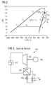
- Fig. 2 shows by way of example a TS diagram for example isopentane as the working medium, in which the cycle of the combined heat and power unit 100 is shown.
- the working medium is printed, for example by means of the feed pump 105 and heated.
- the working medium is evaporated in the evaporator 120 and, for example, overheated to point 4.
- mechanical work is generated between points 4 and 5 in the turbine 130.
- the working medium is cooled and relaxed.
- the working fluid is supplied to the heat exchanger 140.
- the waste heat Q1 is discharged.
- the working medium is at about 48 ° C with a pressure P1 before.
- the working medium is condensed in the condenser 110 and is again present at point 1 in a liquid state at about 48 ° C before.
- the pressure P1 thus represents the condenser pressure.
- the process gradient which is indicative of the efficiency of the process, can be read between points 4 and 6 or 6 '.
- Fig. 2 a conventional cycle process shown. Between the points 1 'and 2, the working fluid is increased, for example, from 80 ° C and a pressure P2 to a higher temperature and a pressure P3. Between points 2 and 4, the working fluid in evaporator 120 is vaporized and overheated. Subsequently, the working medium is supplied to the turbine 130 and relaxed and cooled between the points 4 and 5, so that mechanical work WT is generated. At point 5 or 5 ', the working medium is supplied to the condenser 110 and condensed at a condenser pressure P2 and a temperature of about 80 ° C. The pressure P2 is greater than P1.
Landscapes
- Engineering & Computer Science (AREA)
- Chemical & Material Sciences (AREA)
- Combustion & Propulsion (AREA)
- Mechanical Engineering (AREA)
- General Engineering & Computer Science (AREA)
- Engine Equipment That Uses Special Cycles (AREA)
Abstract
Description
- Die vorliegende Erfindung betrifft eine Kraft-Wärme-Kopplungsanordnung, welche insbesondere nach einem Organic-Rankine-Cycle (ORC) Prozess arbeitet, und ein Verfahren zur Erzeugung von Nutzwärme.
- Kraftwärmekopplungsanlagen, und insbesondere Organic Rankine Cycle (ORC)-Anlagen, werden zur Nutzung von Wärme aus verschiedenen Quellen, wie z.B. Biothermie, Biomassenverbrennung, konzentrierter Sonnenenergie oder Restwärme aus Industrieprozessen, verwendet.
-
Fig. 3 zeigt eine herkömmliche Kraft-Wärme-Kopplungsanordnung 300, welche üblicherweise eine herkömmliche Speisepumpe 305, einen herkömmlichen Kondensator 310, einen herkömmlichen Verdampfer 320 (Erhitzer), eine herkömmliche Turbine 330 (Expander) und einen herkömmlichen Rekuperator 350 aufweist. Typischerweise treibt die herkömmliche Turbine 300 einen herkömmlichen Generator 380 zur Stromerzeugung. - ORC-Anlagen verwenden Arbeitsmittel, deren Verdampfungsverhalten (z.B. Druck, Temperatur) von dem Verdampfungsverhalten von Wasser abweicht. Damit können ORC-Anlagen auch bei niedrigeren Temperaturniveaus als Dampfkreisläufe, entsprechend dem Organic Rankine Cycle-Prozess, effektiv genutzt werden.
- Üblicherweise wird bei ORC-Anlagen, welche als Kraftwärmekopplungsanlagen betrieben werden, das Arbeitsmedium in der herkömmlichen Turbine 330 nicht auf den vorgegebenen Kondensatordruck entspannt. Das Arbeitsmedium wird mit dem herkömmlichen Kondensator 310 mit einem höheren Druck und einer höheren Temperatur zugeführt. In dem herkömmlichen Kondensator 310 erhitzt das Arbeitsmedium ein Nutzwärmemedium aus einem Nutzwärmekreislauf beispielsweise von ca. 60°C auf ca. 90°C. Da in der herkömmlichen Turbine 330 das Arbeitsmedium nicht vollständig expandiert und abgekühlt wird, weist das Arbeitsmedium an dem herkömmlichen Kondensator 310 ein hohes Temperatur- und Druckniveau auf, so dass am herkömmlichen Kondensator 310 eine große Wärmemenge bereitstellbar ist.
- Aufgrund der hohen Temperatur an dem herkömmlichen Kondensator 310 weist dieser eine hohe Kondensatorwärme auf, wodurch wiederum ein hoher Kondensatordruck zum Kondensieren des Arbeitsmediums erforderlich ist. Dieser hohe Kondensatordruck bewirkt zwangsläufig eine deutliche Absenkung der Turbinenleistung der herkömmlichen Turbine 300 und somit des Wirkungsgrades der Stromerzeugung durch den herkömmlichen Generator 380.
- Es ist eine Aufgabe der vorliegenden Erfindung, eine Kraft-Wärmekopplungsanordnung zu schaffen, welche eine hohe Wärmeleistung und Stromerzeugungsleistung aufweist.
- Diese Aufgabe wird mit einer Kraft-Wärme-Kopplungsanordnung, mit einem thermodynamischen System und mit einem Verfahren zur Gewinnung von Nutzwärme gemäß den unabhängigen Ansprüchen beschrieben.
- Gemäß einem ersten Aspekt der vorliegenden Erfindung wird eine Kraft-Wärme-Kopplungsanordnung beschrieben. Die Kraft-Wärme-Kopplungsanordnung weist einen Verdampfer, eine Turbine, einen Wärmetauscher sowie einen Kondensator auf.
- Der Verdampfer ist eingerichtet, ein Arbeitsmedium von einem ersten Zustand, z.B. einem flüssigen Zustand oder einem Zustand mit überkritischem Druck, in einen dampfförmigen (und z.B. überhitzten) oder überkritischen Zustand zu überführen. Die Turbine dient zur Umwandlung von thermischer Energie in mechanische Arbeit, wobei die Turbine mit dem Verdampfer derart gekoppelt ist, dass das Arbeitsmedium von dem Verdampfer der Turbine in einen dampfförmigen Zustand zuführbar ist.
- Der Wärmetauscher ist mit der Turbine gekoppelt, so dass das Arbeitsmedium in dem dampfförmigen Zustand von der Turbine dem Wärmetauscher zuführbar ist. Der Wärmetauscher ist ferner derart mit einer Nutzwärmeanordnung koppelbar, dass thermische Energie von einem Arbeitsmedium an ein Nutzfluid der Nutzwärmeanordnung abgebbar ist.
- Dem Kondensator ist das Arbeitsmedium im dampfförmigen Zustand aus dem Wärmetauscher zuführbar, wobei der Kondensator eingerichtet ist, das Arbeitsmedium mittels Abkühlens von dem dampfförmigen Zustand in den ersten flüssigen Zustand zu überführen. Der Kondensator ist mit dem Verdampfer gekoppelt, so dass das Arbeitsmedium in dem ersten Zustand von dem Kondensator dem Verdampfer zuführbar ist.
- Gemäß einem weiteren Aspekt der vorliegenden Erfindung wird ein thermodynamisches System beschrieben, welches die Kraft-Wärme-Kopplungsanordnung und die Nutzwärmeanordnung aufweist. Der Wärmetauscher ist derart mit der Nutzwärmeanordnung gekoppelt, dass thermische Energie von dem Arbeitsmedium an das Nutzfluid der Nutzwärmeanordnung abgebbar ist.
- Gemäß einem weiteren Aspekt der vorliegenden Erfindung wird ein Verfahren zur Gewinnung von Nutzwärme beschrieben. Gemäß einem weiteren Aspekt der vorliegenden Erfindung wird ein Verfahren zur Gewinnung von Nutzwärme beschrieben. Gemäß dem Verfahren wird ein Arbeitsmedium von einem Verdampfer zu einer Turbine in einem dampfförmigen Zustand zugeführt. Mittels der Turbine wird thermische Energie des Arbeitsmediums in mechanische Arbeit umgewandelt. Das Arbeitsmedium wird in einem dampfförmigen Zustand von der Turbine zu einem Wärmetauscher zugeführt. Thermische Energie wird von dem Arbeitsmedium zu einem Nutzfluid einer Nutzwärme mittels des Wärmetauschers abgegeben. Anschließend wird das Arbeitsmedium in dampfförmigen Zustand von dem Wärmetauscher zu einem Kondensator zugeführt. Das Arbeitsmedium wird von dem dampfförmigen Zustand in den ersten flüssigen Zustand mittels des Kondensators überführt. Anschließend wird das Arbeitsmedium in flüssigem Zustand von dem Kondensator dem Verdampfer zugeführt.
- Die oben beschriebene Kraft-Wärme-Kopplungsanordnung setzt einen thermodynamischen Kreisprozess um. Insbesondere wird ein Clausius-Rankine-Kreisprozess umgesetzt. Wie im Folgenden noch weiter erläutert, kann das Arbeitsmedium aus einem organischen Medium bestehen, sodass die Kraft-Wärme-Kopplungsanordnung insbesondere nach einem "Organic Rankine Cycle(ORC)"-Prozess arbeiten kann.
- Der Clausius-Rankine-Kreisprozess und entsprechend auch der ORC-Kreisprozess weist insbesondere die oben beschriebene Turbine und den Kondensator auf. Zum Antreiben des Kreisprozesses und zur Druckerhöhung des Arbeitsmediums im flüssigen Zustand wird üblicherweise eine Speisepumpe verwendet, um einen Fluss des Arbeitsmediums zwischen den funktionalen Einheiten zu gewährleisten und das Arbeitsmedium zwischen dem Kondensator und dem Verdampfer mit Druck zu beaufschlagen. Rohrleitungen verbinden den Kondensator mit dem Verdampfer, den Verdampfer mit der Turbine und die Turbine mit dem Kondensator. Zwischen dem Kondensator und dem Verdampfer ist die Speisepumpe zwischengeschaltet.
- Gemäß dem Clausius-Rankine-Kreisprozess wird zunächst mechanische Energie erzeugt, indem das Arbeitsmittel in dem Kreisprozess abwechselnd bei niedrigem Druck (Kondensatordruck) kondensiert wird und bei hohem Druck verdampft bzw. in einen überkritischen, dampfförmigen Zustand überführt wird. Der Druck wird von der Speisepumpe durch Aufwand von Arbeit aufgebracht. Ferner wird dem Arbeitsmedium in dem Verdampfer thermische Energie zugeführt. In der Turbine wird aus dem hohen Druck und der thermischen Energie des Arbeitsmediums mechanische Arbeit erzeugt.
- In der Turbine wird das Arbeitsmedium im dampfförmigen Zustand adiabat entspannt, so dass dadurch insbesondere aus der thermischen Energie des Arbeitsmediums mechanische Arbeit erzeugt wird. Anschließend wird in dem Kondensator das Arbeitsmedium im dampfförmigen Zustand nahezu isobar bei einem vorgegebenen Kondensatordruck kondensiert, so dass das Arbeitsmedium anschließend im flüssigen Zustand vorliegt. Anschließend wird in der Speisepumpe der Druck des Arbeitsmediums nahezu adiabat und nahezu isotrop erhöht. Nach der Speisepumpe wird das Arbeitsmedium in flüssigem Zustand oder in dem unterkritischen, dampfförmigen Zustand dem Verdampfer zugeführt, wobei das Arbeitsmedium zunächst bis zum Verdampfungspunkt erwärmt werden kann und dann beispielsweise (nahezu isotherm) verdampft bzw. überhitzt werden kann.
- Bei einer weiteren beispielhaften Ausführungsform wird das dampfförmige Arbeitsmedium in dem Verdampfer durch weitere Erwärmung überhitzt. Das Arbeitsmedium wird in einem überhitzten Zustand, wie oben beschrieben, in der Turbine entspannt, so dass das Risiko einer vorzeitigen Kondensation des Arbeitsmediums in der Turbine reduziert wird.
- Der Kondensator kann beispielsweise als flüssigkeitsgekühlter (z.B. wassergekühlter) Kondensator oder als luftgekühlter Kondensator, welcher beispielsweise einen Ventilator aufweist, ausgebildet sein. Als flüssigkeitsgekühlter Kondensator kann insbesondere ein flüssigkeitsgekühlter Oberflächenkondensator, beispielsweise in der Form eines Rohrbündelwärmeübertragers oder eines Plattenwärmetauschers, eingesetzt werden.
- Die Turbine ist eine Strömungsmaschine, welche die innere Energie des dampfförmigen Arbeitsmediums in Rotationsenergie und letztlich in mechanische Arbeitsenergie umwandelt. Die Turbine weist dazu insbesondere Rotorblätter auf, welche auf einer Abtriebswelle befestigt sind. Aufgrund der Umströmung des Arbeitsmediums an den Rotorblättern wird ein Teil der inneren Energie des Arbeitsmediums, welches beispielsweise aus Bewegungs-, Lage- und Druckenergie zusammengesetzt ist, entzogen, und auf die Rotorblätter übertragen. Dies führt dazu, dass sich die Abtriebswelle der Turbinen in Drehung versetzt, so dass nutzbare Leistung, bzw. mechanische Arbeit, erzeugt wird. Beispielsweise kann an die Abtriebswelle ein Generator oder eine andere Arbeitsmaschine angekoppelt werden.
- Die Nutzwärmeanordnung ist beispielsweise eine Fernwärmeanordnung. Ferner kann die Nutzwärmeanordnung die Nutzwärme des Nutzfluids in z.B. angeschlossenen chemischen Prozessen verwenden.
- Der Verdampfer wandelt das flüssige Arbeitsmedium in einen dampfförmigen und z.B. überkritischen Zustand um. Dazu kann dem Verdampfer thermische Energie, beispielsweise aus einem Verbrennungsprozess, zugeführt werden. Ferner kann der Verdampfer an eine zu kühlende Heizanordnung gekoppelt werden, damit ein Heizfluid der Heizanordnung gekühlt wird und das Arbeitsmedium im Verdampfer erwärmt wird. Der Verdampfer ist beispielsweise ein Wärmetauscher, in welchem in einem ersten Bereich des Wärmetauschers das Arbeitsmedium einspeisbar und abführbar ist und in einem zweiten Bereich das Heizfluid der Heizanordnung einspeisbar und abführbar ist. Der Verdampfer ist derart angeordnet, dass zwischen dem ersten Bereich und dem zweiten Bereich thermische Energie, beispielsweise mittels Konvektion, zwischen dem Heizfluid und dem Arbeitsmedium austauschbar ist.
- Das Heizfluid und das Nutzfluid können als Flüssigkeit, als Dampf oder als Gas vorliegen.
- Bei konventionellen Ansätzen wird der Turbine das Arbeitsmedium abgeführt, bevor es völlig entspannt und abgekühlt ist. Dadurch weist das Arbeitsmedium einen erhöhten Druck und eine hohe Temperatur auf. Aufgrund dieser hohen Werte der Prozessparameter Druck und Temperatur kann in dem Kondensator eine große Wärmemenge bereitgestellt werden, welche ein Nutzfluid einer Nutzanordnung zuführbar ist. Allerdings liegt somit am Kondensator das Arbeitsmedium mit einem hohen Druck vor, so dass der entsprechende Kondensatordruck, bei welchem das Arbeitsmedium kondensiert, ebenfalls hoch ist. Dies wiederum führt dazu, dass eine deutliche Absenkung der Turbinenleistung und des Wirkungsgrads der Stromerzeugung in einem angeschlossenen Generator verursacht wird.
- Mit der vorliegenden Erfindung wird anstelle einer Kondensation des Arbeitsmediums bei hohem Druck in dem Kondensator das Arbeitsmedium vorab einem Wärmetauscher zugeführt, welcher der Turbine nachgeschaltet ist. Das Arbeitsmedium kann somit in der Turbine (z.B. vollständig) entspannen. In dem Wärmetauscher wird dem Arbeitsmedium thermische Energie entnommen und diese Abwärme an ein Nutzfluid der Nutzwärmeanordnung zugeführt. Erst nachdem das Arbeitsmedium in dem Wärmetauscher die thermische Energie an das Nutzfluid abgegeben hat, wird das Arbeitsmedium dem Kondensator zugeführt. Das Arbeitsmedium weist an dem Eingang des Kondensators einen niedrigeren Kondensatordruck im Vergleich zu dem oben beschriebenen konventionellen Vorgehen auf. Mit diesem niedrigeren Kondensatordruck ist zudem eine geringere Kondensationstemperatur notwendig, um das Arbeitsmedium in dem Kondensator von dem gasförmigen Zustand in den flüssigen Zustand zu überführen. Somit wird mit anderen Worten ein niedrigerer Kondensationsdruck des Arbeitsmediums am Kondensatoreingang bereitgestellt, so dass ein höheres Gefälle des Kreisprozesses, insbesondere ein höheres Prozessgefälle zwischen dem Eingang des Arbeitsmediums an der Turbine und dem Eingang des Arbeitsmediums am Kondensator, erzielt wird, so dass eine höhere Leistung aus dem Arbeitsmedium entzogen werden kann (insbesondere Stromleistung).
- Zusammenfassend ist festzustellen, dass mit der oben beschriebenen Kraft-Wärme-Kopplungsanordnung eine effizientere Anordnung zur Erzeugung von mechanischer Arbeit (Strom) einerseits und Nutzwärme andererseits im Vergleich zu konventionellen Ansätzen erzielt werden kann. Die thermische Energie des Prozessfluids trägt zum Betrieb des Kreisprozesses des Systems zur Umwandlung von thermischer Energie in mechanische Arbeit bei.
- Gemäß einer weiteren beispielhaften Ausführungsform ist die Turbine derart eingerichtet, dass das gesamte Arbeitsmedium, welches an einem Turbineneingang der Turbine in die Turbine einspeisbar ist, an einen Turbinenausgang der Turbine abführbar ist. Mit der oben beschriebenen Ausführungsform wird konkretisiert, dass das Arbeitsmedium, welches dem Wärmetauscher und dem Kondensator zuführbar ist, von der letzten Turbinenstufe der Turbine, bzw. der Niederdruckstufe, entnommen wird.
- Gemäß einer weiteren beispielhaften Ausführungsform weist das Arbeitsmedium ein organisches Medium auf, wie beispielsweise ein Silikonöl, Toluol, Isopentan und/oder Isooktan. Ferner kann als organisches Medium auch Kältemittel wie R134a, R236 oder R1234yf verstanden werden. Besteht das Arbeitsmedium aus einem organischen Medium, so kann mittels der Kraft-Wärme-Kopplungsanordnung der sogenannte Organic-Rankine-Cycle (ORC)-Prozess durchgeführt werden. Das organische Arbeitsmedium weist eine niedrigere Verdampfungstemperatur als Wasser auf. Dadurch ist der ORC-Prozess insbesondere bei einen geringen Temperaturgefälle des Arbeitsmediums zwischen dem Verdampfer und dem Kondensator vorteilhaft, da bereits bei einem geringen Temperaturgefälle zwischen dem Verdampfer und dem Kondensator ein effizienter Betrieb des ORC-Prozesses möglich ist.
- Mit der vorliegenden beispielhaften Ausführungsform der Erfindung kann somit effizient Abwärme in einem ORC-Prozess genützt werden. Die Kraft-Wärme-Kopplungsanordnung wird mit dem organischen Arbeitsmedium betrieben, welches die Eigenschaft besitzt, im Vergleich zu Wasser bereits bei moderatem geringem Druck und moderaten Umgebungstemperatur zu kondensieren. In dem Verdampfer reicht eine geringere thermische Energiezufuhr im Vergleich zu Wasser aus, um das organische Arbeitsmedium zu verdampfen.
- Gemäß einer weiteren beispielhaften Ausführungsform ist der Verdampfer derart an eine Heizeinrichtung koppelbar, dass thermische Energie von einem Heizfluid der Heizanordnung an das Arbeitsmedium in dem Verdampfer abgebbar ist. Der Verdampfer ist eingerichtet, das Arbeitsmedium mittels der thermischen Energie aus der Heizanordnung von dem flüssigen Zustand in den dampfförmigen Zustand zu überführen.
- Gemäß einer weiteren beispielhaften Ausführungsform weist die Kraft-Wärmekopplungsanordnung einen ersten Rekuperator mit einem ersten Fluidlauf und einem zweiten Fluidlauf auf. Der erste Rekuperator ist mit dem Wärmetauscher und dem Kondensator derart gekoppelt, dass das Arbeitsmedium von dem Wärmetauscher dem ersten Fluidlauf zuführbar ist und ferner von dem ersten Fluidlauf dem Kondensator zuführbar ist. Der erste Rekuperator ist ferner mit dem Kondensator und dem Verdampfer derart gekoppelt, dass das Arbeitsmedium von dem Kondensator dem zweiten Fluidlauf zuführbar ist und ferner von dem zweiten Fluidlauf dem Verdampfer zuführbar ist. Der erste Fluidlauf und der zweite Fluidlauf sind derart zueinander gekoppelt und angeordnet, dass thermische Energie von dem Arbeitsmedium in dem ersten Fluidlauf, in welchem das Arbeitsmedium insbesondere gasförmig vorliegt, an das Arbeitsmedium in dem zweiten Fluidlauf, in welchem das Arbeitsmedium flüssig vorliegt, übertragbar ist.
- Alternativ kann der Rekuperator ebenfalls zwischen der Turbine und dem Wärmetauscher angeordnet sein, so dass das Arbeitsmedium nach Austritt der Turbine Wärmeenergie an ein Arbeitsmedium, welches den Kondensator durchlaufen hat, zugeführt werden. Entsprechend ist gemäß einer weiteren beispielhaften Ausführungsform ein zweiter Rekuperator mit einem ersten Fluidlauf und einem zweiten Fluidlauf, wobei der zweite Rekuperator mit der Turbine und dem Wärmetauscher derart gekoppelt ist, dass das Arbeitsmedium von der Turbine dem ersten Fluidlauf zuführbar ist und ferner von dem ersten Fluidlauf dem Wärmetauscher zuführbar ist. Der zweite Rekuperator ist ferner mit dem Kondensator und dem Verdampfer derart gekoppelt, dass das Arbeitsmedium von dem Kondensator dem zweiten Fluidlauf zuführbar ist und ferner von dem zweiten Fluidlauf dem Verdampfer zuführbar ist. Der erste Fluidlauf und der zweite Fluidlauf sind derart zueinander angeordnet, dass thermische Energie von dem Arbeitsmedium in dem ersten Fluidlauf an das Arbeitsmedium in dem zweiten Fluidlauf übertragbar ist.
- Mittels des ersten und zweiten Rekuperators wird dem Arbeitsmedium vor dem Kondensator eine Wärmemenge entnommen und dem Arbeitsmedium nach dem Kondensator bzw. vor dem Verdampfer zugeführt. Somit können die Rekuperatoren noch eine Wärmemenge an das dem Verdampfer zuströmende Arbeitsmedium zuführen. Dadurch muss weniger Wärmemenge in dem Verdampfer dem Arbeitsmedium zugeführt werden, um dieses zu verdampfen.
- Gemäß einer weiteren beispielhaften Ausführungsform weist die Kraft-Wärmekopplungsanordnung eine Bypassleitung auf, welche mit der Turbine einerseits und mit dem Kondensator andererseits gekoppelt ist, so dass das Arbeitsmedium in dem dampfförmigen Zustand von der Turbine dem Kondensator direkt zuführbar ist. Mittels der Bypassleitung kann ein beliebiger Anteil des Arbeitsmediums nach der Turbine dem Wärmetauscher zugeführt und ein anderer beliebiger Anteil direkt durch die Bypassleitung dem Kondensator zugeführt werden. Somit kann die Wärmeabgabe des Arbeitsmediums in dem Wärmetauscher an das Nutzfluid gezielt gesteuert werden.
- Ferner weist die Kraft-Wärmekopplungsanordnung ein Steuerventil auf, welches zwischen der Turbine und dem Kondensator derart angeordnet ist, dass ein Massenstrom des Arbeitsmediums, welcher durch die Wärmetauschanordnung fließt, einstellbar ist. Beispielsweise kann ein Steuerventil ein erstes Steuerventil direkt in der Bypassleitung angeordnet sein. Zusätzlich oder alternativ kann ein zweites Steuerventil als Steuerventil in einer Zuleitung zu dem Wärmetauscher angeordnet sein und ein drittes Steuerventil als Steuerventil nach dem Wärmetauscher in einer entsprechenden Leitung angeordnet sein. Die entnehmbaren Wärmemengen und ihre Temperaturen können durch die Steuerung des Massenstroms, welcher durch den Wärmetauscher fließt, gezielt beeinflusst werden.
- Gemäß einer weiteren beispielhaften Ausführungsform weist die Kraft-Wärmekopplungsanordnung einen dritten Rekuperator mit einem ersten Fluidlauf und einem zweiten Fluidlauf auf, wobei der dritte Rekuperator in der Bypassleitung derart angeordnet ist, dass zumindest ein Teil des Arbeitsmediums von der Turbine dem ersten Fluidlauf zuführbar ist und ferner von dem ersten Fluidlauf dem Kondensator zuführbar ist. Der dritte Rekuperator ist ferner mit dem Kondensator und dem Verdampfer derart gekoppelt, dass das Arbeitsmedium von dem Kondensator dem zweiten Fluidlauf zuführbar ist und ferner von dem zweiten Fluidlauf dem Verdampfer zuführbar ist. Der erste Fluidlauf und der zweite Fluidlauf sind derart zueinander angeordnet, dass thermische Energie von dem Arbeitsmedium in dem ersten Fluidlauf an das Arbeitsmedium in dem zweiten Fluidlauf übertragbar ist.
- Gemäß einer weiteren beispielhaften Ausführungsform weist die Kraft-Wärmekopplungsanordnung eine Steuereinrichtung auf, welche den Bedarf an Nutzwärme ermittelt und daraufhin das Steuerventil derart steuern kann, dass ein gewünschter Massenstrom des Arbeitsmediums von der Turbine zu dem Wärmetauscher geleitet wird.
- Gemäß einer weiteren beispielhaften Ausführungsform weist die Kraftstoff-Wärmekopplungsanordnung einen Generator auf, welcher mit der Turbine derart gekoppelt ist, dass der Generator mittels der Turbine antreibbar ist.
- In der Kraft-Wärmekopplungsanordnung muss am Kondensator ein bestimmter Kondensatordruck mit einer bestimmten Temperatur vorliegen, um das Arbeitsmedium zu kondensieren bzw. auf einen bestimmten unterkritischen Verdampfungszustand zu bringen. Mit einem Wärmetauscher gemäß der vorliegenden Erfindung ist gezielt der Massenstrom und z.B. die Temperatur des Arbeitsmediums einstellbar, ohne dass ein bestimmter höherer Kondensatordruck eingehalten werden muss. Dies erhöht im Vergleich zu konventionellen Ansätzen die Flexibilität der bereitstellbaren Wärmemenge, da weniger auf die Drücke des Arbeitsmediums geachtet werden muss.
- Es wird darauf hingewiesen, dass die hier beschriebenen Ausführungsformen lediglich eine beschränkte Auswahl an möglichen Ausführungsvarianten der Erfindung darstellen. So ist es möglich, die Merkmale einzelner Ausführungsformen in geeigneter Weise miteinander zu kombinieren, so dass für den Fachmann mit den hier expliziten Ausführungsvarianten eine Vielzahl von verschiedenen Ausführungsformen als offensichtlich offenbart anzusehen sind.
- Im Folgenden werden zur weiteren Erläuterung und zum besseren Verständnis der vorliegenden Erfindung Ausführungsbeispiele unter Bezugnahme auf die beigefügten Figuren näher beschrieben.
-
Fig. 1 zeigt eine beispielhafte Ausführungsform der Kraft-Wärmekopplungsanordnung gemäß einer beispielhaften Ausführungsform der vorliegenden Erfindung; -
Fig. 2 zeigt ein T-S-Diagramm, in welchem ein beispielhafter Kreisprozess der Kraft-Wärmekopplungsanordnung gemäß einem Ausführungsbeispiel der vorliegenden Erfindung dargestellt wird; und -
Fig. 3 zeigt eine herkömmliche Kraft-Wärme-Kopplungsanordnung. - Gleiche oder ähnliche Komponenten sind in den Figuren mit gleichen Bezugsziffern versehen. Die Darstellungen in den Figuren sind schematisch und nicht maßstäblich.
-
Fig. 1 zeigt eine Kraft-Wärmekopplungsanordnung 100. Die Kraft-Wärmekopplungsanordnung 100 weist einen Verdampfer 120, eine Turbine 130, einen Wärmetauscher 140 und einen Kondensator 110 auf. Der Verdampfer 120 ist eingerichtet, ein Arbeitsmedium von dem ersten Zustand, z.B. einem flüssigen Zustand, in einen dampfförmigen (und z.B. überhitzten) Zustand zu überführen. Die Turbine 130 dient zur Umwandlung von thermischer Energie in mechanische Arbeit. Beispielsweise kann mittels der erzeugten mechanischen Arbeit ein Generator 180 zur Erzeugung elektrischer Energie angekoppelt werden. Die Turbine 130 ist mit dem Verdampfer 120 derart gekoppelt, dass das Arbeitsmedium von dem Verdampfer 120 der Turbine in einem dampfförmigen Zustand zuführbar ist. - Der Wärmetauscher 140 ist mit der Turbine 130 gekoppelt ist, so dass das Arbeitsmedium in dem dampfförmigen Zustand von der Turbine 130 dem Wärmetauscher 140 zuführbar ist.
- Der Wärmetauscher 140 ist derart mit einer Nutzwärmeanordnung 170 koppelbar, dass thermische Energie von dem Arbeitsmedium an ein Nutzfluid der Nutzwärmeanordnung 170 abgebbar ist.
- Der Kondensator 110, welchem das Arbeitsmedium in dampfförmigen Zustand aus dem Wärmetauscher 140 und/oder aus der Turbine 130 zuführbar ist, ist eingerichtet, das Arbeitsmedium mittels Kühlens von dem dampfförmigen Zustand in einen flüssigen Zustand oder einen unterkritisch, dampfförmigen Zustand zu überführen. Der Kondensator 110 ist mit dem Verdampfer 120 gekoppelt, so dass das Arbeitsmedium in dem flüssigen Zustand oder dem unterkritisch, dampfförmigen Zustand von dem Kondensator dem Verdampfer zuführbar ist.
- Wie in
Fig. 1 dargestellt, ist der Wärmetauscher 140 nach der Turbine 130 angeordnet. Das Arbeitsmedium, welches die Turbine 130 verlässt, kann einerseits durch eine Bypassleitung 104 direkt dem Kondensator 140 zugeführt werden oder dem Wärmetauscher 140 zugeführt werden. - Zur Steuerung des Massenstroms des Arbeitsmediums, welches dem Wärmetauscher 140 zugeführt wird, dienen Steuerventile 101, 102, 103. Beispielsweise kann ein erstes Steuerventil 101 in der Bypassleitung 104 angeordnet werden. Ein zweites Steuerventil 102 kann in einer Zuführleitung zum Wärmetauscher 140 angeordnet sein und/oder ein drittes Steuerventil 103 kann in einer Abfuhrleitung des Wärmetauschers 140 angeordnet sein.
- Die Turbine 130 ist insbesondere derart eingerichtet, dass das gesamte Arbeitsmedium, welches an einem Turbineneingang der Turbine in die Turbine einspeisbar ist, an einem Turbinenausgang der Turbine abführbar ist. Von dem Turbinenausgang wird das Arbeitsmedium direkt der Bypassleitung 104 und/oder dem Wärmetauscher 140 zugeführt. An die Wärmetauschanordnung 140 ist die Nutzwärmeanordnung 170 gekoppelt. In dem Wärmetauscher 140 wird eine Abwärme Q1 von dem Arbeitsmedium auf das Nutzfluid abgegeben. Das Nutzfluid kann beispielsweise eine gewisse Vorlauftemperatur von beispielsweise ungefähr 50-70° C aufweisen, wobei in dem Wärmetauscher mittels der Abwärme Q1 des Arbeitsmediums das Nutzfluid auf ca. 90° C aus dem Wärmetauscher 140 abgeführt werden.
- In dem Kondensator 110 wird das Arbeitsmedium kondensiert. Der Kondensator 110 weist beispielsweise eine Luftkühlung (Gebläse, Ventilator) auf. Ferner kann dem Kondensator 110 ein Kühlmittel zugeführt werden, an welches das Arbeitsmedium Kondensationswärme bzw. Abwärme Q2 abgibt. Da das Arbeitsmedium bereits in dem Wärmetauscher 140 thermische Energie abgegeben hat, ist das Druckniveau und das Temperaturniveau des Arbeitsmediums im Kondensator 110 gering, so dass bei Raumtemperatur von ca. 20-30°C und einem entsprechend geringen Kondensatordruck das Arbeitsmedium kondensiert oder auf einen unterkritischen, dampfförmigen Zustand gebracht werden kann.
- Ferner kann optional vor dem Kondensator 110, wie in
Fig. 1 dargestellt, ein erster Rekuperator 150, ein zweiter Rekuperator 152 und/oder ein dritter Rekuperator 153 zwischengeschaltet werden. - Der erste Rekuperator 150 weist einen ersten Fluidlauf und einen zweiten Fluidlauf auf. Im ersten Fluidlauf durchströmt das Arbeitsmedium, welches dem Kondensator 110 zuführbar ist, den ersten Rekuperator 150. Der zweite Fluidlauf wird durch das flüssige Arbeitsmedium durchströmt, welches aus dem Kondensator 110 kommt. In dem ersten Rekuperator 150 wird ein Wärmeübergang Q4 erzeugt, wodurch das Arbeitsmedium in dem ersten Fluidlauf thermische Energie an das Arbeitsmedium in dem zweiten Fluidlauf abgibt. Somit kann das Arbeitsmedium vor Eintritt in den Kondensator 110 weiter abgekühlt werden, so dass weniger Abwärme Q2 am Kondensator 110 abgeführt werden muss. Darüber hinaus ist weniger Wärmezufuhr Q3 am Verdampfer 160 zur Verdampfung des Arbeitsmediums notwendig, da im ersten Rekuperator 150 das Arbeitsmedium bereits vorgewärmt wird.
- Der zweite Rekuperator 152 weist entsprechend einen ersten Fluidlauf und einen zweiten Fluidlauf auf. Im ersten Fluidlauf durchströmt das Arbeitsmedium, welches aus der Turbine 130 eingespeist wird und dem Wärmetauscher 140 zuführbar ist, den zweiten Rekuperator 152. Der zweite Fluidlauf wird durch das flüssige Arbeitsmedium durchströmt, welches beispielsweise aus dem Kondensator 110 kommt. In dem zweiten Rekuperator 152 wird ein Wärmeübergang erzeugt, wodurch das Arbeitsmedium in dem ersten Fluidlauf thermische Energie an das Arbeitsmedium in dem zweiten Fluidlauf abgibt.
- Der dritte Rekuperator 153 weist entsprechend einen ersten Fluidlauf und einen zweiten Fluidlauf auf. Im ersten Fluidlauf durchströmt das Arbeitsmedium, welches aus der Turbine 130 eingespeist wird und dem Kondensator 110 oder dem ersten Rekuperator 150 zuführbar ist, den dritten Rekuperator 153. Der zweite Fluidlauf wird durch das flüssige Arbeitsmedium durchströmt, welches beispielsweise aus dem Kondensator 110 kommt. In dem dritten Rekuperator 153 wird ein Wärmeübergang erzeugt, wodurch das Arbeitsmedium in dem ersten Fluidlauf thermische Energie an das Arbeitsmedium in dem zweiten Fluidlauf abgibt.
- Zwischen dem Kondensator 110 und dem Verdampfer 120 ist zudem eine Speisepumpe 105 angeordnet, welche bevorzugt isotherm den Druck im flüssigen Arbeitsmedium erhöht.
- An dem Verdampfer 120 wird eine Wärmezufuhr Q3 zugeführt, um das Arbeitsmedium im Verdampfer 120 zu verdampfen. Die thermische Energie kann von einer Heizanordnung 160 stammen, welche die Wärmezufuhr Q3 am Verdampfer 120 bereitstellt. Die Heizanordnung 160 kann dadurch gekühlt werden. Die Heizanordnung 160 weist beispielsweise einen internen chemischen Prozess auf, welcher gekühlt werden muss. Ferner kann die Heizanordnung 160 beispielsweise eine beliebige Arbeitsmaschine darstellen, welche gekühlt werden muss. Diese Kühlung kann beispielsweise durch die Kopplung an den Verdampfer 120 bereitgestellt werden, um eine Wärmezufuhr Q3 von der Heizanordnung 160 zu dem Verdampfer 120 bereitzustellen. Somit kann auch Prozesswärme (heiße Abgasströme) genutzt werden.
- Da im Vergleich zu herkömmlichen Ansätzen mit der beschriebenen Kraft-Wärmekopplungsanordnung 100 bereits im Wärmetauscher 140 Abwärme Q1 entnommen wird (und optional am Kondensator 110 und am Rekuperator 150) ist die Kondensationstemperatur und der Kondensatordruck des Arbeitsmediums am Kondensator 110 geringer als bei herkömmlichen Anordnungen. Bei herkömmlichen Anordnungen wird direkt von der Turbine 130 das Arbeitsmedium dem Kondensator 110 zugeführt, um dort Abwärme an die Nutzwärmeanordnung 170 abzugeben. Hierdurch ist ein hoher Kondensatordruck im Kondensator 110 gegeben.
-
Fig. 2 zeigt beispielhaft ein T-S-Diagramm für z.B. Isopentan als Arbeitsmedium, in welchem der Kreisprozess der Kraft-Wärmekopplungsanordnung 100 dargestellt wird. Zwischen den Punkten 1 und 2 wird das Arbeitsmedium beispielsweise mittels der Speisepumpe 105 bedruckt und erwärmt. Zwischen den Punkten 2 und 3 wird das Arbeitsmedium in dem Verdampfer 120 verdampft und beispielsweise bis zum Punkt 4 überhitzt. Anschließend wird zwischen den Punkten 4 und 5 in der Turbine 130 mechanische Arbeit erzeugt. Dadurch wird das Arbeitsmedium abgekühlt und entspannt. Nach Ausgang der Turbine 130 wird das Arbeitsmedium dem Wärmetauscher 140 zugeführt. In dem Wärmetauscher 140 wird die Abwärme Q1 abgegeben. An Punkt 6' liegt das Arbeitsmedium bei ca. 48°C mit einem Druck P1 vor. Zwischen den Punkten 6'-1 wird das Arbeitsmedium in dem Kondensator 110 kondensiert und liegt an Punkt 1 erneut in flüssigem Zustand bei ca. 48°C vor. Der Druck P1 stellt somit den Kondensatordruck dar. - Das Prozessgefälle, welches indikativ für den Wirkungsgrad des Prozesses ist, kann zwischen den Punkten 4 und 6 bzw. 6' abgelesen werden.
- Ferner ist in
Fig. 2 ein herkömmlicher Kreisprozess dargestellt. Zwischen den Punkten 1' und 2 wird das Arbeitsmedium beispielsweise von 80°C und einem Druck P2 auf eine höhere Temperatur und einen Druck P3 erhöht. Zwischen den Punkten 2 und 4 wird das Arbeitsmedium in dem Verdampfer 120 verdampft und überhitzt. Anschließend wird das Arbeitsmedium der Turbine 130 zugeführt und zwischen den Punkten 4 und 5 entspannt und abgekühlt, so dass mechanische Arbeit WT erzeugt wird. An dem Punkt 5 bzw. 5' wird das Arbeitsmedium dem Kondensator 110 zugeführt und bei einem Kondensatordruck P2 und einer Temperatur von ungefähr 80° C kondensiert. Der Druck P2 ist größer als P1. - Aus
Fig. 2 wird deutlich, dass das Prozessgefälle zwischen den Punkten 4 und 5 in dem herkömmlichen Prozess geringer ist als das Prozessgefälle zwischen den Punkten 4 und 6 gemäß dem neuen Kreisprozess der erfindungsgemäßen Kraft-Wärmekopplungsanordnung 100. Dies zeigt die erhöhte Effizienz der Kraft-Wärmekopplungsanordnung 100 gemäß der vorliegenden Erfindung. - Ergänzend ist darauf hinzuweisen, dass "umfassend" keine anderen Elemente oder Schritte ausschließt und "eine" oder "ein" keine Vielzahl ausschließt. Ferner sei darauf hingewiesen, dass Merkmale oder Schritte, die mit Verweis auf eines der obigen Ausführungsbeispiele beschrieben worden ist, auch in Kombination mit anderen Merkmalen oder Schritten anderer oben beschriebener Ausführungsbeispiele verwendet werden können. Bezugszeichen in den Ansprüchen sind nicht als Einschränkung anzusehen.
Claims (12)
- Kraft-Wärme-Kopplungsanordnung (100) aufweisend
einen Verdampfer (120),
wobei der Verdampfer (120) eingerichtet ist ein Arbeitsmedium von einem ersten Zustand, insbesondere einem flüssigen Zustand, in einen dampfförmigen Zustand zu überführen,
eine Turbine (130) zur Umwandlung von thermischer Energie in mechanische Arbeit,
wobei die Turbine (130) mit dem Verdampfer (120) derart gekoppelt ist, dass das Arbeitsmedium von dem Verdampfer (120) der Turbine (130) in dem dampfförmigen Zustand zuführbar ist,
einen Wärmetauscher (140), welcher mit der Turbine (130) gekoppelt ist, so dass das Arbeitsmedium von der Turbine (130) in dem dampfförmigen Zustand dem Wärmetauscher (140) zuführbar ist,
wobei der Wärmetauscher (140) derart mit einer Nutzwärmeanordnung (170) koppelbar ist, dass thermische Energie vom dem Arbeitsmedium an ein Nutzfluid der Nutzwärmeanordnung (170) abgebbar ist, und
einen Kondensator (110), welchem das Arbeitsmedium aus dem Wärmetauscher (140) in dampfförmigen Zustand zuführbar ist,
wobei der Kondensator (110) eingerichtet ist das Arbeitsmedium mittels Abkühlens von dem dampfförmigen Zustand in den ersten Zustand zu überführen, und
wobei der Kondensator (110) mit dem Verdampfer (120) gekoppelt ist, so dass das Arbeitsmedium in dem ersten Zustand von dem Kondensator (110) dem Verdampfer (120) zuführbar ist. - Kraft-Wärme-Kopplungsanordnung (100) gemäß Anspruch 1, wobei die Turbine (130) derart eingerichtet ist, dass das gesamte Arbeitsmedium, welches an einem Turbineneingang der Turbine (130) in die Turbine (130) einspeisbar ist, an einem Turbinenausgang der Turbine (130) abführbar ist.
- Kraft-Wärme-Kopplungsanordnung (100) gemäß Anspruch 1 oder 2,
wobei das Arbeitsmedium ein organisches Medium, insbesondere Silikonöl, Toluol, Iso-Pentan, Iso-Oktan, R134a, R236, R1234ze und/oder R1234yf, aufweist. - Kraft-Wärme-Kopplungsanordnung (100) gemäß einem der Ansprüche 1 bis 3,
wobei der Verdampfer (120) derart an eine Heizanordnung (160) koppelbar ist, dass thermische Energie von einem Heizfluid der Heizanordnung (160) an das Arbeitsmedium in dem Verdampfer (120) abgebbar ist, und
wobei der Verdampfer (120) eingerichtet ist das Arbeitsmedium mittels der thermischen Energie aus der Heizanordnung (160) von dem flüssigen Zustand in den dampfförmigen Zustand zu überführen. - Kraft-Wärme-Kopplungsanordnung (100) gemäß einem der Ansprüche 1 bis 4, ferner aufweisend
einen ersten Rekuperator (150) mit einem ersten Fluidlauf und einem zweiten Fluidlauf,
wobei der erste Rekuperator (150) mit dem Wärmetauscher (140) und dem Kondensator (110) derart gekoppelt ist, dass das Arbeitsmedium von dem Wärmetauscher (140) dem ersten Fluidlauf zuführbar ist und ferner von dem ersten Fluidlauf dem Kondensator (110) zuführbar ist,
wobei der erste Rekuperator (150) ferner mit dem Kondensator (110) und dem Verdampfer (120) derart gekoppelt ist, dass das Arbeitsmedium von dem Kondensator (110) dem zweiten Fluidlauf zuführbar ist und ferner von dem zweiten Fluidlauf dem Verdampfer (120) zuführbar ist, und
wobei der erste Fluidlauf und der zweite Fluidlauf derart zueinander angeordnet sind, dass thermische Energie von dem Arbeitsmedium in dem ersten Fluidlauf an das Arbeitsmedium in dem zweiten Fluidlauf übertragbar ist. - Kraft-Wärme-Kopplungsanordnung (100) gemäß einem der Ansprüche 1 bis 5, ferner aufweisend
einen zweiten Rekuperator (152) mit einem ersten Fluidlauf und einem zweiten Fluidlauf,
wobei der zweite Rekuperator (152) mit der Turbine (130) und dem Wärmetauscher (140) derart gekoppelt ist, dass das Arbeitsmedium von der Turbine (130) dem ersten Fluidlauf zuführbar ist und ferner von dem ersten Fluidlauf dem Wärmetauscher (140) zuführbar ist,
wobei der zweite Rekuperator (152) ferner mit dem Kondensator (110) und dem Verdampfer (120) derart gekoppelt ist, dass das Arbeitsmedium von dem Kondensator (110) dem zweiten Fluidlauf zuführbar ist und ferner von dem zweiten Fluidlauf dem Verdampfer (120) zuführbar ist, und
wobei der erste Fluidlauf und der zweite Fluidlauf derart zueinander angeordnet sind, dass thermische Energie von dem Arbeitsmedium in dem ersten Fluidlauf an das Arbeitsmedium in dem zweiten Fluidlauf übertragbar ist. - Kraft-Wärme-Kopplungsanordnung (100) gemäß einem der Ansprüche 1 bis 6, ferner aufweisend
eine Bypassleitung (104), welche mit der Turbine (130) und mit dem Kondensator (110) gekoppelt ist, so dass zumindest ein Teil des Arbeitsmediums in dem dampfförmigen Zustand von der Turbine (130) dem Kondensator (110) direkt zuführbar ist. - Kraft-Wärme-Kopplungsanordnung (100) gemäß Anspruch 7, ferner aufweisend
einen dritten Rekuperator (153) mit einem ersten Fluidlauf und einem zweiten Fluidlauf,
wobei der dritte Rekuperator (153) in der Bypassleitung (104) derart angeordnet ist, dass das zumindest ein Teil des Arbeitsmediums von der Turbine (130) dem ersten Fluidlauf zuführbar ist und ferner von dem ersten Fluidlauf dem Kondensator (110) zuführbar ist,
wobei der dritte Rekuperator (153) ferner mit dem Kondensator (110) und dem Verdampfer (120) derart gekoppelt ist, dass das Arbeitsmedium von dem Kondensator (110) dem zweiten Fluidlauf zuführbar ist und ferner von dem zweiten Fluidlauf dem Verdampfer (120) zuführbar ist, und
wobei der erste Fluidlauf und der zweite Fluidlauf derart zueinander angeordnet sind, dass thermische Energie von dem Arbeitsmedium in dem ersten Fluidlauf an das Arbeitsmedium in dem zweiten Fluidlauf übertragbar ist. - Kraft-Wärme-Kopplungsanordnung (100) gemäß Anspruch 7 oder 8, ferner aufweisend
ein Steuerventil (101; 102; 103), welches zwischen der Turbine (130) und dem Kondensator (110) angeordnet ist, so dass ein Massenstrom des Arbeitsmediums, welcher durch den Wärmtauscher (140) fließt, einstellbar ist. - Kraft-Wärme-Kopplungsanordnung (100) gemäß einem der Ansprüche 1 bis 9, ferner aufweisend
einen Generator (180), welcher mit der Turbine (130) gekoppelt ist, so dass der Generator (180) mittels der Turbine (130) antreibbar ist. - Thermodynamisches System, aufweisend
die Kraft-Wärme-Kopplungsanordnung (100) gemäß einem der Ansprüche 1 bis 10, und
die Nutzwärmeanordnung (170),
wobei der Wärmetauscher (140) derart mit der Nutzwärmeanordnung (170) gekoppelt ist, dass thermische Energie vom dem Arbeitsmedium an das Nutzfluid der Nutzwärmeanordnung (170) abgebbar ist. - Verfahren zur Gewinnung von Nutzwärme, das Verfahren aufweisend
Zuführen eines Arbeitsmediums von einem Verdampfer (120) zu einer Turbine (130) in einem dampfförmigen Zustand,
Umwandeln von thermischer Energie des Arbeitsmediums in mechanische Arbeit mittels der Turbine (130),
Zuführen des Arbeitsmediums in dem dampfförmigen Zustand von der Turbine (130) zu einem Wärmetauscher (140),
Abgeben von thermischer Energie von dem Arbeitsmedium zu einem Nutzfluid einer Nutzwärmeanordnung (170) mittels des Wärmetauschers (140),
Zuführen des Arbeitsmediums in dampfförmigen Zustand von dem Wärmetauscher (140) zu einem Kondensator(110),
Überführen des Arbeitsmediums von dem dampfförmigen Zustand in einen ersten Zustand, insbesondere einem flüssigen Zustand, mittels des Kondensators (110), und
Zuführen des Arbeitsmediums in dem ersten Zustand von dem Kondensator (110) zu dem Verdampfer (120).
Priority Applications (1)
| Application Number | Priority Date | Filing Date | Title |
|---|---|---|---|
| PL13195007T PL2762691T3 (pl) | 2013-01-31 | 2013-11-29 | Instalacja ORC z poprawionym wytwarzaniem ciepła |
Applications Claiming Priority (1)
| Application Number | Priority Date | Filing Date | Title |
|---|---|---|---|
| DE102013201639.5A DE102013201639A1 (de) | 2013-01-31 | 2013-01-31 | ORC-Anlage mit verbesserter Wärmebereitstellung |
Publications (2)
| Publication Number | Publication Date |
|---|---|
| EP2762691A1 true EP2762691A1 (de) | 2014-08-06 |
| EP2762691B1 EP2762691B1 (de) | 2017-06-28 |
Family
ID=49726515
Family Applications (1)
| Application Number | Title | Priority Date | Filing Date |
|---|---|---|---|
| EP13195007.3A Active EP2762691B1 (de) | 2013-01-31 | 2013-11-29 | ORC-Anlage mit verbesserter Wärmebereitstellung |
Country Status (3)
| Country | Link |
|---|---|
| EP (1) | EP2762691B1 (de) |
| DE (1) | DE102013201639A1 (de) |
| PL (1) | PL2762691T3 (de) |
Cited By (1)
| Publication number | Priority date | Publication date | Assignee | Title |
|---|---|---|---|---|
| CN114127392A (zh) * | 2019-07-19 | 2022-03-01 | 西门子能源环球有限责任两合公司 | 用于将热能转变成机械能的系统 |
Citations (6)
| Publication number | Priority date | Publication date | Assignee | Title |
|---|---|---|---|---|
| US4267692A (en) * | 1979-05-07 | 1981-05-19 | Hydragon Corporation | Combined gas turbine-rankine turbine power plant |
| US20030213246A1 (en) * | 2002-05-15 | 2003-11-20 | Coll John Gordon | Process and device for controlling the thermal and electrical output of integrated micro combined heat and power generation systems |
| WO2008101711A2 (de) * | 2007-02-25 | 2008-08-28 | Deutsche Energie Holding Gmbh | Mehrstufiger orc-kreislauf mit zwischenenthitzung |
| US20090126381A1 (en) * | 2007-11-15 | 2009-05-21 | The Regents Of The University Of California | Trigeneration system and method |
| DE202012007723U1 (de) * | 2012-08-13 | 2012-10-19 | Michael Mayer | Vorrichtung zur Optimierung des inneren Wirkungsgrades eines Organic-Rankine-Prozesses mittels eines Rekuperator-Zwischenkreislaufs |
| WO2014000830A1 (de) * | 2012-06-26 | 2014-01-03 | Energy Intelligence Lab Gmbh | Vorrichtung zum erzeugen elektrischer energie mittels eines orc-kreislaufs |
Family Cites Families (1)
| Publication number | Priority date | Publication date | Assignee | Title |
|---|---|---|---|---|
| FI98858C (fi) * | 1994-01-24 | 1997-08-25 | Abb Installaatiot Oy | Menetelmä termisen energian jakelujärjestelmän yhteydessä ja termisen energian jakelujärjestelmä |
-
2013
- 2013-01-31 DE DE102013201639.5A patent/DE102013201639A1/de not_active Withdrawn
- 2013-11-29 PL PL13195007T patent/PL2762691T3/pl unknown
- 2013-11-29 EP EP13195007.3A patent/EP2762691B1/de active Active
Patent Citations (6)
| Publication number | Priority date | Publication date | Assignee | Title |
|---|---|---|---|---|
| US4267692A (en) * | 1979-05-07 | 1981-05-19 | Hydragon Corporation | Combined gas turbine-rankine turbine power plant |
| US20030213246A1 (en) * | 2002-05-15 | 2003-11-20 | Coll John Gordon | Process and device for controlling the thermal and electrical output of integrated micro combined heat and power generation systems |
| WO2008101711A2 (de) * | 2007-02-25 | 2008-08-28 | Deutsche Energie Holding Gmbh | Mehrstufiger orc-kreislauf mit zwischenenthitzung |
| US20090126381A1 (en) * | 2007-11-15 | 2009-05-21 | The Regents Of The University Of California | Trigeneration system and method |
| WO2014000830A1 (de) * | 2012-06-26 | 2014-01-03 | Energy Intelligence Lab Gmbh | Vorrichtung zum erzeugen elektrischer energie mittels eines orc-kreislaufs |
| DE202012007723U1 (de) * | 2012-08-13 | 2012-10-19 | Michael Mayer | Vorrichtung zur Optimierung des inneren Wirkungsgrades eines Organic-Rankine-Prozesses mittels eines Rekuperator-Zwischenkreislaufs |
Cited By (1)
| Publication number | Priority date | Publication date | Assignee | Title |
|---|---|---|---|---|
| CN114127392A (zh) * | 2019-07-19 | 2022-03-01 | 西门子能源环球有限责任两合公司 | 用于将热能转变成机械能的系统 |
Also Published As
| Publication number | Publication date |
|---|---|
| EP2762691B1 (de) | 2017-06-28 |
| DE102013201639A1 (de) | 2014-07-31 |
| PL2762691T3 (pl) | 2017-12-29 |
Similar Documents
| Publication | Publication Date | Title |
|---|---|---|
| EP2347102B1 (de) | Verfahren zum betreiben eines thermodynamischen kreislaufes sowie thermodynamischer kreislauf | |
| DE112015007268B4 (de) | Abwärmerückgewinnungssystem, mit diesem ausgestattete gasturbinenanlage und installationsverfahren für das abwärmerückgewinnungssystem | |
| EP2368021B1 (de) | Abhitzedampferzeuger sowie ein verfahren zum verbesserten betrieb eines abhitzedampferzeugers | |
| DE112016001240B4 (de) | Einlassluftkühlverfahren, einlassluftkühlvorrichtung zum ausführen des verfahrens und abwärmerückgewinnungseinrichtung und gasturbinenanlage jeweils umfassend die einlassluftkühlvorrichtung | |
| DE102010060428A1 (de) | Kombinationszyklus-Kraftwerk mit integrierter ORC-Vorrichtung | |
| DE102012220188B4 (de) | Integrierter ORC-Prozess an zwischengekühlten Kompressoren zur Erhöhung des Wirkungsgrades und Verringerung der erforderlichen Antriebsleistung durch Nutzung der Abwärme | |
| DE102011054744A1 (de) | Wärmetauscher für ein Kombikraftwerk | |
| CH702163A2 (de) | Verfahren zur Steigerung der Leistungsabgabe eines Gas- und Dampf-Kombikraftwerks während ausgewählter Betriebszeiträume. | |
| EP2187051A1 (de) | Verfahren und Vorrichtung zur Zwischenüberhitzung in einem solarthermischen Kraftwerk mit indirekter Verdampfung | |
| EP0158629B1 (de) | Dampfkreislauf für Dampfkraftanlagen | |
| DE202012001522U1 (de) | Anlage zur energieeffizienten Umwandlung der Abwärme aus Verbrennungskraftmaschinen in mechanische oder elektrische Energie | |
| WO2005056994A1 (de) | Luftspeicherkraftanlage | |
| DE102010004079A1 (de) | Brennkraftmaschine, kombiniert mit Rankineprozess zur effizienten Nutzung der Kühlmittel- und Abgaswärme | |
| DE102012110579B4 (de) | Anlage und Verfahren zur Erzeugung von Prozessdampf | |
| EP2762691B1 (de) | ORC-Anlage mit verbesserter Wärmebereitstellung | |
| DE202010017143U1 (de) | ORC-Direktverdampfer für Biomassefeuerungen | |
| DE102015012673A1 (de) | Vorrichtung zur Abwärmerückgewinnung | |
| EP2561276A2 (de) | Rankine-prozess (rc) oder organischer rankine-prozess (orc) für die abwärmenachverstromung bei biomasseverbrennung, sowie entsprechende einrichtung | |
| DE102009043720A1 (de) | Carnotisierter Rankineprozess für Solarthermische Kraftwerke | |
| DE102010056516A1 (de) | ORC-Direktverdampfer für Biomassefeuerungen | |
| DE102008005036A1 (de) | Verbrennungskraftmaschine mit Wärmerückgewinnungsvorrichtung | |
| DE102016220634A1 (de) | Abwärme-Kraftanlage mit stufenweiser Wärmezufuhr | |
| EP2138677B1 (de) | Gas- und Dampfturbinenanlage | |
| DE102019217996A1 (de) | Vorrichtung und Verfahren zur Ausspeicherung eines thermischen Energiespeichers, insbesondere eines Schüttgutspeichers | |
| DE202012007723U1 (de) | Vorrichtung zur Optimierung des inneren Wirkungsgrades eines Organic-Rankine-Prozesses mittels eines Rekuperator-Zwischenkreislaufs |
Legal Events
| Date | Code | Title | Description |
|---|---|---|---|
| PUAI | Public reference made under article 153(3) epc to a published international application that has entered the european phase |
Free format text: ORIGINAL CODE: 0009012 |
|
| 17P | Request for examination filed |
Effective date: 20131129 |
|
| AK | Designated contracting states |
Kind code of ref document: A1 Designated state(s): AL AT BE BG CH CY CZ DE DK EE ES FI FR GB GR HR HU IE IS IT LI LT LU LV MC MK MT NL NO PL PT RO RS SE SI SK SM TR |
|
| AX | Request for extension of the european patent |
Extension state: BA ME |
|
| R17P | Request for examination filed (corrected) |
Effective date: 20141219 |
|
| RBV | Designated contracting states (corrected) |
Designated state(s): AL AT BE BG CH CY CZ DE DK EE ES FI FR GB GR HR HU IE IS IT LI LT LU LV MC MK MT NL NO PL PT RO RS SE SI SK SM TR |
|
| GRAP | Despatch of communication of intention to grant a patent |
Free format text: ORIGINAL CODE: EPIDOSNIGR1 |
|
| STAA | Information on the status of an ep patent application or granted ep patent |
Free format text: STATUS: GRANT OF PATENT IS INTENDED |
|
| INTG | Intention to grant announced |
Effective date: 20170203 |
|
| GRAS | Grant fee paid |
Free format text: ORIGINAL CODE: EPIDOSNIGR3 |
|
| GRAA | (expected) grant |
Free format text: ORIGINAL CODE: 0009210 |
|
| STAA | Information on the status of an ep patent application or granted ep patent |
Free format text: STATUS: THE PATENT HAS BEEN GRANTED |
|
| AK | Designated contracting states |
Kind code of ref document: B1 Designated state(s): AL AT BE BG CH CY CZ DE DK EE ES FI FR GB GR HR HU IE IS IT LI LT LU LV MC MK MT NL NO PL PT RO RS SE SI SK SM TR |
|
| REG | Reference to a national code |
Ref country code: GB Ref legal event code: FG4D Free format text: NOT ENGLISH |
|
| REG | Reference to a national code |
Ref country code: CH Ref legal event code: EP |
|
| REG | Reference to a national code |
Ref country code: AT Ref legal event code: REF Ref document number: 905042 Country of ref document: AT Kind code of ref document: T Effective date: 20170715 |
|
| REG | Reference to a national code |
Ref country code: IE Ref legal event code: FG4D Free format text: LANGUAGE OF EP DOCUMENT: GERMAN |
|
| REG | Reference to a national code |
Ref country code: DE Ref legal event code: R096 Ref document number: 502013007614 Country of ref document: DE |
|
| RAP2 | Party data changed (patent owner data changed or rights of a patent transferred) |
Owner name: SIEMENS AKTIENGESELLSCHAFT |
|
| REG | Reference to a national code |
Ref country code: CH Ref legal event code: NV Representative=s name: SIEMENS SCHWEIZ AG, CH Ref country code: CH Ref legal event code: PCOW Free format text: NEW ADDRESS: WERNER-VON-SIEMENS-STRASSE 1, 80333 MUENCHEN (DE) |
|
| PG25 | Lapsed in a contracting state [announced via postgrant information from national office to epo] |
Ref country code: GR Free format text: LAPSE BECAUSE OF FAILURE TO SUBMIT A TRANSLATION OF THE DESCRIPTION OR TO PAY THE FEE WITHIN THE PRESCRIBED TIME-LIMIT Effective date: 20170929 Ref country code: FI Free format text: LAPSE BECAUSE OF FAILURE TO SUBMIT A TRANSLATION OF THE DESCRIPTION OR TO PAY THE FEE WITHIN THE PRESCRIBED TIME-LIMIT Effective date: 20170628 Ref country code: NO Free format text: LAPSE BECAUSE OF FAILURE TO SUBMIT A TRANSLATION OF THE DESCRIPTION OR TO PAY THE FEE WITHIN THE PRESCRIBED TIME-LIMIT Effective date: 20170928 Ref country code: HR Free format text: LAPSE BECAUSE OF FAILURE TO SUBMIT A TRANSLATION OF THE DESCRIPTION OR TO PAY THE FEE WITHIN THE PRESCRIBED TIME-LIMIT Effective date: 20170628 Ref country code: LT Free format text: LAPSE BECAUSE OF FAILURE TO SUBMIT A TRANSLATION OF THE DESCRIPTION OR TO PAY THE FEE WITHIN THE PRESCRIBED TIME-LIMIT Effective date: 20170628 |
|
| REG | Reference to a national code |
Ref country code: NL Ref legal event code: MP Effective date: 20170628 |
|
| REG | Reference to a national code |
Ref country code: LT Ref legal event code: MG4D |
|
| REG | Reference to a national code |
Ref country code: FR Ref legal event code: PLFP Year of fee payment: 5 |
|
| PG25 | Lapsed in a contracting state [announced via postgrant information from national office to epo] |
Ref country code: LV Free format text: LAPSE BECAUSE OF FAILURE TO SUBMIT A TRANSLATION OF THE DESCRIPTION OR TO PAY THE FEE WITHIN THE PRESCRIBED TIME-LIMIT Effective date: 20170628 Ref country code: BG Free format text: LAPSE BECAUSE OF FAILURE TO SUBMIT A TRANSLATION OF THE DESCRIPTION OR TO PAY THE FEE WITHIN THE PRESCRIBED TIME-LIMIT Effective date: 20170928 Ref country code: SE Free format text: LAPSE BECAUSE OF FAILURE TO SUBMIT A TRANSLATION OF THE DESCRIPTION OR TO PAY THE FEE WITHIN THE PRESCRIBED TIME-LIMIT Effective date: 20170628 Ref country code: NL Free format text: LAPSE BECAUSE OF FAILURE TO SUBMIT A TRANSLATION OF THE DESCRIPTION OR TO PAY THE FEE WITHIN THE PRESCRIBED TIME-LIMIT Effective date: 20170628 Ref country code: RS Free format text: LAPSE BECAUSE OF FAILURE TO SUBMIT A TRANSLATION OF THE DESCRIPTION OR TO PAY THE FEE WITHIN THE PRESCRIBED TIME-LIMIT Effective date: 20170628 |
|
| PG25 | Lapsed in a contracting state [announced via postgrant information from national office to epo] |
Ref country code: SK Free format text: LAPSE BECAUSE OF FAILURE TO SUBMIT A TRANSLATION OF THE DESCRIPTION OR TO PAY THE FEE WITHIN THE PRESCRIBED TIME-LIMIT Effective date: 20170628 Ref country code: EE Free format text: LAPSE BECAUSE OF FAILURE TO SUBMIT A TRANSLATION OF THE DESCRIPTION OR TO PAY THE FEE WITHIN THE PRESCRIBED TIME-LIMIT Effective date: 20170628 Ref country code: RO Free format text: LAPSE BECAUSE OF FAILURE TO SUBMIT A TRANSLATION OF THE DESCRIPTION OR TO PAY THE FEE WITHIN THE PRESCRIBED TIME-LIMIT Effective date: 20170628 |
|
| PG25 | Lapsed in a contracting state [announced via postgrant information from national office to epo] |
Ref country code: IS Free format text: LAPSE BECAUSE OF FAILURE TO SUBMIT A TRANSLATION OF THE DESCRIPTION OR TO PAY THE FEE WITHIN THE PRESCRIBED TIME-LIMIT Effective date: 20171028 Ref country code: ES Free format text: LAPSE BECAUSE OF FAILURE TO SUBMIT A TRANSLATION OF THE DESCRIPTION OR TO PAY THE FEE WITHIN THE PRESCRIBED TIME-LIMIT Effective date: 20170628 Ref country code: SM Free format text: LAPSE BECAUSE OF FAILURE TO SUBMIT A TRANSLATION OF THE DESCRIPTION OR TO PAY THE FEE WITHIN THE PRESCRIBED TIME-LIMIT Effective date: 20170628 |
|
| REG | Reference to a national code |
Ref country code: DE Ref legal event code: R097 Ref document number: 502013007614 Country of ref document: DE |
|
| PG25 | Lapsed in a contracting state [announced via postgrant information from national office to epo] |
Ref country code: DK Free format text: LAPSE BECAUSE OF FAILURE TO SUBMIT A TRANSLATION OF THE DESCRIPTION OR TO PAY THE FEE WITHIN THE PRESCRIBED TIME-LIMIT Effective date: 20170628 |
|
| PLBE | No opposition filed within time limit |
Free format text: ORIGINAL CODE: 0009261 |
|
| 26N | No opposition filed |
Effective date: 20180329 |
|
| PG25 | Lapsed in a contracting state [announced via postgrant information from national office to epo] |
Ref country code: MC Free format text: LAPSE BECAUSE OF FAILURE TO SUBMIT A TRANSLATION OF THE DESCRIPTION OR TO PAY THE FEE WITHIN THE PRESCRIBED TIME-LIMIT Effective date: 20170628 |
|
| GBPC | Gb: european patent ceased through non-payment of renewal fee |
Effective date: 20171129 |
|
| PG25 | Lapsed in a contracting state [announced via postgrant information from national office to epo] |
Ref country code: CH Free format text: LAPSE BECAUSE OF NON-PAYMENT OF DUE FEES Effective date: 20171130 Ref country code: LI Free format text: LAPSE BECAUSE OF NON-PAYMENT OF DUE FEES Effective date: 20171130 |
|
| PG25 | Lapsed in a contracting state [announced via postgrant information from national office to epo] |
Ref country code: LU Free format text: LAPSE BECAUSE OF NON-PAYMENT OF DUE FEES Effective date: 20171129 Ref country code: SI Free format text: LAPSE BECAUSE OF FAILURE TO SUBMIT A TRANSLATION OF THE DESCRIPTION OR TO PAY THE FEE WITHIN THE PRESCRIBED TIME-LIMIT Effective date: 20170628 |
|
| REG | Reference to a national code |
Ref country code: BE Ref legal event code: MM Effective date: 20171130 |
|
| REG | Reference to a national code |
Ref country code: IE Ref legal event code: MM4A |
|
| PG25 | Lapsed in a contracting state [announced via postgrant information from national office to epo] |
Ref country code: MT Free format text: LAPSE BECAUSE OF FAILURE TO SUBMIT A TRANSLATION OF THE DESCRIPTION OR TO PAY THE FEE WITHIN THE PRESCRIBED TIME-LIMIT Effective date: 20170628 |
|
| PG25 | Lapsed in a contracting state [announced via postgrant information from national office to epo] |
Ref country code: IE Free format text: LAPSE BECAUSE OF NON-PAYMENT OF DUE FEES Effective date: 20171129 |
|
| PG25 | Lapsed in a contracting state [announced via postgrant information from national office to epo] |
Ref country code: BE Free format text: LAPSE BECAUSE OF NON-PAYMENT OF DUE FEES Effective date: 20171130 Ref country code: GB Free format text: LAPSE BECAUSE OF NON-PAYMENT OF DUE FEES Effective date: 20171129 |
|
| PG25 | Lapsed in a contracting state [announced via postgrant information from national office to epo] |
Ref country code: HU Free format text: LAPSE BECAUSE OF FAILURE TO SUBMIT A TRANSLATION OF THE DESCRIPTION OR TO PAY THE FEE WITHIN THE PRESCRIBED TIME-LIMIT; INVALID AB INITIO Effective date: 20131129 |
|
| PG25 | Lapsed in a contracting state [announced via postgrant information from national office to epo] |
Ref country code: CY Free format text: LAPSE BECAUSE OF NON-PAYMENT OF DUE FEES Effective date: 20170628 |
|
| PG25 | Lapsed in a contracting state [announced via postgrant information from national office to epo] |
Ref country code: MK Free format text: LAPSE BECAUSE OF FAILURE TO SUBMIT A TRANSLATION OF THE DESCRIPTION OR TO PAY THE FEE WITHIN THE PRESCRIBED TIME-LIMIT Effective date: 20170628 |
|
| REG | Reference to a national code |
Ref country code: AT Ref legal event code: MM01 Ref document number: 905042 Country of ref document: AT Kind code of ref document: T Effective date: 20181129 |
|
| PG25 | Lapsed in a contracting state [announced via postgrant information from national office to epo] |
Ref country code: AT Free format text: LAPSE BECAUSE OF NON-PAYMENT OF DUE FEES Effective date: 20181129 |
|
| PG25 | Lapsed in a contracting state [announced via postgrant information from national office to epo] |
Ref country code: TR Free format text: LAPSE BECAUSE OF FAILURE TO SUBMIT A TRANSLATION OF THE DESCRIPTION OR TO PAY THE FEE WITHIN THE PRESCRIBED TIME-LIMIT Effective date: 20170628 |
|
| PG25 | Lapsed in a contracting state [announced via postgrant information from national office to epo] |
Ref country code: PT Free format text: LAPSE BECAUSE OF FAILURE TO SUBMIT A TRANSLATION OF THE DESCRIPTION OR TO PAY THE FEE WITHIN THE PRESCRIBED TIME-LIMIT Effective date: 20170628 |
|
| PG25 | Lapsed in a contracting state [announced via postgrant information from national office to epo] |
Ref country code: AL Free format text: LAPSE BECAUSE OF FAILURE TO SUBMIT A TRANSLATION OF THE DESCRIPTION OR TO PAY THE FEE WITHIN THE PRESCRIBED TIME-LIMIT Effective date: 20170628 |
|
| REG | Reference to a national code |
Ref country code: DE Ref legal event code: R081 Ref document number: 502013007614 Country of ref document: DE Owner name: SIEMENS ENERGY GLOBAL GMBH & CO. KG, DE Free format text: FORMER OWNER: SIEMENS AKTIENGESELLSCHAFT, 80333 MUENCHEN, DE |
|
| STAA | Information on the status of an ep patent application or granted ep patent |
Free format text: STATUS: NO OPPOSITION FILED WITHIN TIME LIMIT |
|
| PGFP | Annual fee paid to national office [announced via postgrant information from national office to epo] |
Ref country code: DE Payment date: 20241128 Year of fee payment: 12 |
|
| PGFP | Annual fee paid to national office [announced via postgrant information from national office to epo] |
Ref country code: PL Payment date: 20241105 Year of fee payment: 12 |
|
| PGFP | Annual fee paid to national office [announced via postgrant information from national office to epo] |
Ref country code: FR Payment date: 20241126 Year of fee payment: 12 |
|
| PGFP | Annual fee paid to national office [announced via postgrant information from national office to epo] |
Ref country code: CZ Payment date: 20241113 Year of fee payment: 12 |
|
| PGFP | Annual fee paid to national office [announced via postgrant information from national office to epo] |
Ref country code: IT Payment date: 20241125 Year of fee payment: 12 |