EP2762382B1 - Resource management plan creation device, method thereof, and program - Google Patents
Resource management plan creation device, method thereof, and program Download PDFInfo
- Publication number
- EP2762382B1 EP2762382B1 EP12835240.8A EP12835240A EP2762382B1 EP 2762382 B1 EP2762382 B1 EP 2762382B1 EP 12835240 A EP12835240 A EP 12835240A EP 2762382 B1 EP2762382 B1 EP 2762382B1
- Authority
- EP
- European Patent Office
- Prior art keywords
- node
- management
- train
- resource
- merge
- Prior art date
- Legal status (The legal status is an assumption and is not a legal conclusion. Google has not performed a legal analysis and makes no representation as to the accuracy of the status listed.)
- Active
Links
Images





Classifications
-
- G—PHYSICS
- G06—COMPUTING OR CALCULATING; COUNTING
- G06Q—INFORMATION AND COMMUNICATION TECHNOLOGY [ICT] SPECIALLY ADAPTED FOR ADMINISTRATIVE, COMMERCIAL, FINANCIAL, MANAGERIAL OR SUPERVISORY PURPOSES; SYSTEMS OR METHODS SPECIALLY ADAPTED FOR ADMINISTRATIVE, COMMERCIAL, FINANCIAL, MANAGERIAL OR SUPERVISORY PURPOSES, NOT OTHERWISE PROVIDED FOR
- G06Q10/00—Administration; Management
- G06Q10/06—Resources, workflows, human or project management; Enterprise or organisation planning; Enterprise or organisation modelling
-
- B—PERFORMING OPERATIONS; TRANSPORTING
- B61—RAILWAYS
- B61L—GUIDING RAILWAY TRAFFIC; ENSURING THE SAFETY OF RAILWAY TRAFFIC
- B61L27/00—Central railway traffic control systems; Trackside control; Communication systems specially adapted therefor
- B61L27/10—Operations, e.g. scheduling or time tables
- B61L27/12—Preparing schedules
-
- B—PERFORMING OPERATIONS; TRANSPORTING
- B61—RAILWAYS
- B61L—GUIDING RAILWAY TRAFFIC; ENSURING THE SAFETY OF RAILWAY TRAFFIC
- B61L27/00—Central railway traffic control systems; Trackside control; Communication systems specially adapted therefor
- B61L27/10—Operations, e.g. scheduling or time tables
- B61L27/18—Crew rosters; Itineraries
-
- G—PHYSICS
- G06—COMPUTING OR CALCULATING; COUNTING
- G06Q—INFORMATION AND COMMUNICATION TECHNOLOGY [ICT] SPECIALLY ADAPTED FOR ADMINISTRATIVE, COMMERCIAL, FINANCIAL, MANAGERIAL OR SUPERVISORY PURPOSES; SYSTEMS OR METHODS SPECIALLY ADAPTED FOR ADMINISTRATIVE, COMMERCIAL, FINANCIAL, MANAGERIAL OR SUPERVISORY PURPOSES, NOT OTHERWISE PROVIDED FOR
- G06Q50/00—Information and communication technology [ICT] specially adapted for implementation of business processes of specific business sectors, e.g. utilities or tourism
- G06Q50/40—Business processes related to the transportation industry
Definitions
- the present invention relates to a resource management plan creation device, a resource management plan creation method, and a resource management plan creation program. More specifically, the present invention relates to technique that enables to create the resource management plan for managing the resource, for example, a moving medium (vehicle and airframe), crew members in transport services, especially railroad and aviation industries in consideration of the management completion site of the resource.
- a moving medium vehicle and airframe
- crew members in transport services, especially railroad and aviation industries in consideration of the management completion site of the resource.
- a maintenance work plan of resources (moving media) used for operation and an operation plan for crews are considered in parallel with the management of an operation schedule.
- resources moving media
- an operation plan for crews are considered in parallel with the management of an operation schedule.
- a period of vehicular inspection is legally prescribed so that inspection work is required to be regularly executed to adhere to the inspection period while efficiently allocating the vehicle to the train.
- the continuous duty periods and work hours of the crew members are legally prescribed that have to be posted to the duty on board while following the legal approach.
- resource management plan Such a plan in consideration of the resource management will be hereinafter referred to as "resource management plan”.
- a vehicle allocated to the train is required to be selected out of massive combination, considering a characteristic of an individual vehicle such as a type and the performance, the timing of a shuttle at a station, the time of return to a car depot for inspection and the like. It is manually difficult work.
- the crew member management plan the crew member to work on board of the train is required to be selected out of massive combination, considering each characteristic of the crew member such as working conditions and the duty histories, a time taken for transfer or transfer timing, and break time.
- the creation of the resource management plan for the railroad is not sufficiently systematized with respect to the vehicle and the crew members. For this reason, the manual creation relies on experiences of experts.
- Patent Document 1 and Non-Patent Document 1 provide a means to recreate a resource management plan also in consideration of an inspection period based on a train timetable changed to recover from disruptions.
- Patent Document 2 provides a means to find a location in which unscheduled inspection work can be executed based on inquiry about the connection of trains, and to create a resource management plan into which an extraordinary inspection work is inserted.
- Patent Document 3 provides a means to accept a desirable pattern from a user about a shuttle of a train and a vehicle allocated to a train, and to create the resource management plan in consideration of the intention of a user about connection of trains.
- Non-Patent Document 1 Freight Train Locomotive Rescheduling Problem after Disruptions” by Keisuke Sato and Naoto Fukumura, IPSJ SIG Notes 2009 (19), 141-144, 2009-02-26 Furthermore the Patent Document JP-2010-285053 A discloses a device which replans once there are deviations from the timetable.
- management pattern When a resource management plan is created, it is important not only to meet characteristics of vehicles and crew members, and an operation schedule but to secure the regularity of management (so called management pattern). For example, in case of the railroad, a vehicle expected to have large-scale inspection is stored in a car depot all day before the inspection as a spare vehicle, and a period for a deposit as a spare vehicle is intentionally considered so as to equalize travel distances and running days among multiple vehicles. Such regularity is an important element not only to execute periodic maintenance work but to enable usual maintenance work and usual vehicle storage work on the spot. Likewise, for the crew member, there is a management pattern intended to regularly allocate the day off and to equalize the time for duty on board.
- the vehicle having its management of the day completed is stored in the station yard at which the management of the vehicle is completed or in the adjacent car depot so as to start the management from the site on the following day. If the operational schedule is disrupted, the station where the management of the vehicle is completed (management completion site) is changed.
- the train different from the one specified in the original plan has to be allocated to the vehicle on the next day, thus causing interruption with the management pattern and omission of executing the inspection work.
- the railroad operator takes the measure to return the vehicle as a deadhead train having the management completion station changed to the station as specified in the original plan if necessary, thus causing lower resource management efficiency.
- the technique as disclosed in the aforementioned documents is intended to create the management plan, aiming at efficient management in the time range to be planed, however, the conditions for the deposit site are not considered.
- a resource management plan creation device is configured to be realized by a computer which includes a storage unit for storing information, an output unit for outputting the information, an input unit for inputting the information, and a processing unit for executing a program, wherein the storage unit stores operation schedule information of a transport service, and wherein the processing unit executes the program to provide: an operation schedule read unit for reading the operation schedule information of the transport service preliminarily stored in the storage unit, a network creation unit which creates a network model for transport routes by generating a node having at least a starting site, a start time, a terminal site and a termination time of each transport route as attributes, and generating each path for connecting nodes representing each transport route that allows a continuous operation using a same resource based on the attributes of the respective nodes with respect to multiple transport routes contained in the operation schedule based on the operation schedule information, generates a management starting node with at least information for identifying a management starting site of each resource and a vehicle as the attributes, and a management completion
- a resource management plan creation method is realized by a computer which includes a storage unit for storing operation schedule information of a transport service, an output unit for outputting information, an input unit for inputting the information, and a processing unit for executing a program.
- the method includes the steps of reading the operation schedule information stored in the storage unit, based on the operation schedule with respect to each of multiple transport routes contained in the operation schedule, providing a network model for transport routes by generating a node with at least a starting site, a start time, a terminal site and termination time of each transport route as attributes, and generating each path for connecting the nodes representing each transport route that allows continuous operation using the same resource based on the attributes of the respective nodes, generating a management starting node with at least information for identifying a management starting site of each resource and a vehicle, and a management completion node with at least information for identifying each management completion site and each resource as the attributes, generating each path for connecting the nodes representing each transport route that allows allocation of the resource represented by the management starting node and the management starting node, generating each path for connecting the nodes which have values of the attributes of the management completion node at the management completion site accorded with those of the other node at a completion site, and generating
- the program for creating the resource management plan according to the present invention is configured as a program executable on a computer to create the resource management plan.
- the present invention allows creation of the management plan without changing the resource management completion site or the number of resources which stay in the management completion site from the original plan.
- FIG. 1 is a block diagram showing an example of the configuration of a resource management plan creation device.
- a resource management plan creation device 1000 is configured by a computer which includes a memory 1001, a storage unit 1100, a display unit 1200, an input unit 1201, a processing unit (CPU) 1202, a communication unit 1203, and a data bus 1204 that connects those elements.
- the resource management plan creation device 1000 is connected to an external terminal device and the like via a communication network.
- the display unit 1200 is an output unit such as a liquid crystal display for visualizing the information, and configured to display the information to a user such as a state and a result of the process executed by the resource management plan creation device 1000.
- the input unit 1201 is a device such as a keyboard and a mouse configured to accept the input from the user for inputting an instruction to the computer.
- the processing unit 1202 executes various programs stored in the memory 1001.
- the communication unit 1203 exchanges various data and commands with another device via a local area network (LAN) and others.
- the storage unit 1100 stores various data for the resource management plan creation device 1000 to execute the process.
- the memory 1001 holds various programs 1002 and temporary data for the resource management plan creation device 1000 to execute the process.
- the storage unit 1100 stores original route information 1, operation information 2, resource information 3, route information 4, mergeable site information 5 and merge candidate information 6.
- the memory 1001 stores the program 1002 which is executed by the processing unit 1202 to realize various function units including an operation schedule read unit 1003, a network creation unit 1004, a merge candidate determination unit 1005, a merge candidate incorporating unit 1006, and a plan creation unit 1007.
- the operation schedule read unit 1003 reads the operation information 2 stored in the storage unit 1100.
- the network creation unit 1004 creates a network model representing the resource management plan based on the operation information read by the operation schedule read unit 1003. The network model will be described in detail later referring to FIG. 6 .
- the merge candidate determination unit 1005 calculates the management completion station for each resource based on the operation information read by the operation schedule read unit 1003, and determines a route as the candidate to which multiple resources are allocated based on the calculated result.
- the merge candidate incorporating unit 1006 changes the network model created by the network creation unit 1004 based on the route determined by the merge candidate determination unit 1005 as being the candidate to which the multiple resources are allocated.
- the changed network model will be described in detail referring to FIG. 7 .
- the plan creation unit 1007 generates constraint conditions based on the network model which has been created by the network creation unit 1004 and changed by the merge candidate incorporating unit 1006, creates the resource management plan to meet the resultant constraint conditions, and present the created resource management plan to the user via the display unit 1200.
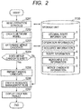
- FIG. 2 is a flowchart showing a basic procedure for processing operations of the resource management plan creation device 1000.
- the operation schedule read unit 1003 reads the operation information 2 stored in the storage unit 1100 (S201).
- the network creation unit 1004 creates the network model representing the management plan of the resource such as the vehicle based on the operation schedule read by the operation schedule read unit 1003 (S202).
- the network model to be generated will be described in detail referring to FIG. 6 , and the method of generating the network model will be described in detail referring to FIG. 10 .
- the merge candidate determination unit 1005 determines the routes (hereinafter referred to as a merge candidate) as the candidates to which multiple resources are allocated based on the operation schedule read in S201 and the mergeable site information 5 stored in the storage unit 1100 (S203). In the case of railroad, for example, the determination is made with respect to the train as the merge train candidate.
- the merge train represents the one formed by connecting multiple train sets so as to run as the single train.
- the train set represents a set of multiple vehicles allocated to the train.
- the merge candidate determination method will be described in detail referring to FIG. 11 .
- the merge candidate determination unit 1005 determines whether there is the trains determined as the merge candidates in S203. If there is at least one candidate, the process S205 is executed for incorporating the merge candidates to the network model created in S202. If there is no merge candidate, the process S206 is executed for creating the resource management plan (S204).
- the merge candidate incorporating unit 1006 adds nodes representing the trains as the merge candidates determined in S203 and links to the network model created in S202 (S205).
- the network model to which the merge candidates are added will be described in detail referring to FIG. 7 .
- the plan creation unit 1007 generates a mathematical model formulated as the vehicle routing problem based on the network model created in a series of processes from S201 to S205, and creates the resource management plan which meets conditions represented by the mathematical model (S206).
- the mathematical model to be created and the plan creation procedure will be described in detail referring to FIG. 13 .
- the plan creation unit 1007 displays the resultant resource management plan created in S206 on the display unit 1200 (S207) for informing the user. If the multiple plans are created in S206, all the resultant plans will be displayed.
- the original route information 1 relates to the route which has been planned before starting the operation, and the item is formed by adding the starting station and terminal station for the respective trains to that of the subsequent route information 4.
- the operation information 2 represents the one which defines the route for each minimum unit of the transport service.
- the train is the minimum unit of the transport service in the railroad, which is defined by the station at which the train stops or bypasses between the starting station and the terminal station, the arrival-departure time or passing time at each station.
- the resource information 3 defines the resource used for the transport service.
- the resource information of the railroad includes the one about the vehicle and the crew.
- the information that defines the vehicle is represented by the vehicle name or identification number for uniquely identifying the vehicle, the maintenance work (inspection and cleaning) expected to be carried out on the day of operation, the time at which the maintenance work may be carried out, the maintenance work site, and the route identification number for uniquely identifying the transport service (corresponding to the train in the case of railroad), which is allocated to the vehicle.
- the route information 4 defines the order of executing the minimum units of the transport service by the single resource.
- the route information is formed by listing the train information allocated to the single train set in consideration of turn back operation, and pull-in/pull-out of the car depot ( FIG. 3A ).
- the train information represents the train name or the train ID for uniquely identifying the train.
- FIG. 3B represents allocation of trains to three train sets. Specifically, the single train set is allocated to the trains 1, 4 and 8. Likewise, the single train set is allocated to the trains 2, 5, 7, and another single train set is allocated to the trains 3, 6 and 10, respectively.
- the mergeable site information 5 defines the site which allows the work of merging or separating the multiple resources.
- the mergeable site information defines the station that allows merging or separation of the multiple train sets, or the station linked to the car depot.
- FIG. 4 shows an example of the mergeable site information 5 in the case of railroad, for example.
- a target track 51 stores the ID or the track name for uniquely identifying the track to be defined.
- a mergeable site 52 denotes the station which belongs to the track identified by the target track 51, and stores the ID or the station name for uniquely identifying the station which allows execution of the merging work.
- a separable site 53 denotes the station that belongs to the track identified by the target track 51, and stores the ID or the station name for uniquely identifying the station that allows the separation work.
- records 54 indicate that the stations A and C among those belong to the track A allow the merging work, and the station C allows the separation work.
- the merge candidate information 6 stores the route determined as the merge candidate by the merge candidate determination unit 1005, or the preliminarily determined merge candidate, if any. In the case of railroad, it is the information for defining the train as the merge candidate.
- FIG. 5 shows an example of the merge candidate information.
- a merging section 61 stores the section between stations, on which the train runs as the merge train.
- a merge candidate 62 stores the train as the merge candidate.
- a mergeable number 63 stores the maximum number of the mergeable train sets as the merge train. For example, the record 64 represents that the maximum of two additional train sets can be merged with the original train set to form the train 5 which may run on the merging section between stations A and C.
- FIGS. 3A and 3B The relevant operation of the embodiment will be described referring to FIGS. 3A and 3B .
- the model of the resource management plan will be described referring to FIG. 6 .
- each function and operation of the respective processing units of the resource management creation device 1000 will be described in detail referring to FIGS. 7 to 13 .
- the embodiment assumes the work for rescheduling the vehicle management which is carried out when the operation of trains disrupts.
- the rescheduling for the vehicle management is carried out when the accident or failure of the vehicle unexpectedly change the train operation schedule by changing the allocation of the vehicle to the train in accordance with the changed operation schedule.
- a means for changing the allocation of the vehicle includes a means for changing the train allocated at the terminal station, a means for temporarily pulling out the spare train that stays in the car depot, and a means for temporarily storing the vehicle in the car depot.
- the vehicle is required by law to be regularly inspected in accordance with the travel distances and running days. In rescheduling the vehicle management, the vehicle allocation is changed by combining the aforementioned means in consideration of the inspection which is determined so as not to exceed the inspection cycle.
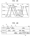
- FIG. 3 shows charts used in the transport service of railroad and data used in this embodiment as the example.
- FIG. 3A shows an example of the operation schedule of trains.
- the operation schedule of trains is generated based on the operation information 2.
- a vertical axis 31 in FIG. 3A denotes stations, and a horizontal axis 32 denotes time.
- One train is represented by drawing a line from a starting station to a terminal station of the train with the passage of time (referred to as a train line).
- a train line For example, a thick line 33 represents one train that leaves the station C about six o'clock and arrives at the station A about six thirty.
- a line segment 34 that connects two train lines represents a group of trains allocated to one train set.
- the trains 1, 4 and 8 are connected as a group of series of trains, which means that the single train set runs in the order of these.
- a mark represented by " ⁇ " such as a sign 35 denotes timing at which the train set is pulled out of the car depot.
- the sign 35 shows that the train set is pulled out of the car depot adjacent to the station C in accordance with departure of the train 1.
- a mark represented by " ⁇ " represents timing at which the train set is stored in the car depot.
- the sign 36 shows that after the train 6 arrives, the train set allocated to the vehicle 6 is stored is stored in the car depot adjacent to the station A.
- FIG. 3B shows the allocation of the trains to the respective train sets.
- the train allocation is made based on the resource information 3 and the route information 4.
- FIG. 3B is expressed with a horizontal axis 41, a train set name 42, and allocation information 43.
- the axis 41 denotes time
- the train set name 42 denotes the name for uniquely identifying the train set.
- the allocation information 43 denotes the allocation of the vehicle to the train set indicated by the train set 42.
- Each train to be allocated is represented by one horizontal bar (for example, a horizontal bar 44), and a train name (for example, train name 45) is put aside the horizontal bar.
- the sign indicating the expected work is displayed.
- a sign 46 represents that the train set C is expected to have the maintenance work, specifically, an inspection A after running as the train 6.
- the record 47 denotes a route allocated to the train set C, representing that after it runs as the train 3, it then runs as the train 6, and after work of the inspection A is done, it runs as the train 10.
- FIG. 3A shows that the train 6 is stored in the car depot adjacent to the station A after the run, and the train 10 is pulled out of the car depot adjacent to the station A. Therefore, it is known that after the train set C is once stored in the car depot after it runs as the trains 3 and 6, it is pulled out of the car depot again and runs as the train 10.
- FIG. 6 shows the network model of the resource management plan. In an example shown in FIG. 6 , some links are omitted for simplicity.
- FIG. 6 shows the network model representing a candidate that can be formed into the route, which includes a train set node, a train node, an end node, a connection link and an end link.
- the train set node represents a train set to which the route is allocated.
- One train set node is set per train set.
- the train set node has start time in a time zone in which the train set is available, termination time in a time zone in which the train set is available, a position in which the train set is kept standby at operation start time (a station adjacent to the car depot where the train set is kept standby or a station where it is kept standby), a starting station and a terminal station of the route in the original plan as attributes.
- the train node represents a train included in the operation schedule. One train node is set per one train.
- the train node has a starting station, a terminal station, start time and termination time of the train as attributes.
- the end node represents an end of the route.
- One end node is set per one train set.
- the end node has a train set name or train set ID for uniquely identifying the train set, and a terminal station of the route planned in the original plan as attributes.
- the end node 61 represents an end of the route of the train set A.
- the train 8 is the end of the route of the train set A in the original plan and in the example as shown in FIG. 3A , the train 8 arrives at the station A. Therefore, a value of an attribute of the terminal station of the end node 61 is the station A.
- connection link means a directed link that links the train nodes, the train set node and the train node, and the train node and the end node, which will be generated as follows.
- the connection link between the train nodes is generated based on a starting station, start time, terminal station, and termination time of the train respectively represented by the train node so that the connection between time and station is established.
- the train node 63 represents the train 1, and the starting station of it is the station C, a terminal station is the station A, start time is six o'clock, and termination time is six thirty.
- the node 64 represents the train 4, and the starting station of it is the station A, a terminal station is the station C, start time is six forty, and termination time is seven five.
- the terminal station of the node 63 is the same as the starting station of the node 64 by comparison between the two train nodes, the connection is established.
- the connection link from the node 63 to the node 64 may be established. Likewise, it is possible to generate the connection link towards the nodes representing the train 5, the train 3, and the train 10 from the node 63.
- a weight that facilitates selection as solution is set to the connection link between the trains continuously allocated to the same train in the original resource management plan compared to any other connection link.
- the route is created by searching a round route with the smallest weight of the link on the network shown in FIG. 6 in this embodiment, which will be described in detail later. Therefore, a small weight value is set to the connection link between the trains continuously allocated to the same train set in the original resource management plan.
- a plan having as few changes from the original plan as possible can be acquired.
- the following description of the weight that facilitates selection as the connection link has the same meaning.
- the connection link between the train node and the train set node is generated to establish the connection between time and site based on the starting station, start time, terminal station and termination time represented by the train node, and the start time and end time in the time zone when the train set is available, and the train set position at the start of the management, which are represented by the train set node.
- the time zone which allows the use of the train set (train set A) represented by the train set node 62 is 6 o'clock
- the start location is the station C.
- the connection link is generated from the train set node 62 towards the train node representing the train that departs the station C at 6 o'clock or later as the start time. That is, the connection link towards the train nodes representing the trains 1, 2, 6 and 8 is generated.
- connection link that represents the same allocation as the original resource management plan
- weight that facilitates selection as solution is set compared with any other link.
- the connection link between the train node and the end node is generated from the train node that can be set as a final train of the route toward the end node.
- the train that can be set as the final train of the route basically means the train that finally arrives at a station adjacent to the car depot or the station yard which allows deposit of the train until the next day. In the meantime, the case that can't be set the train, it is not desirable since the train is redirected to store the vehicle in the car depot.
- the weight that facilitates selection as solution compared with any other link is set to the connection link between the train node and the end node representing the train at the end of the route in the original plan.
- the end link is a link for restricting so that the train set terminates the route at a point scheduled in the original resource management plan.
- the end link is generated from one end node towards all train set nodes, and sets the weight based on the restriction of the route termination point. That is, a value of the terminal station in the original resource management plan held by the end node and a value of the terminal station in the resource management plan held by the train set node are compared. When those values are the same, the weight value is set to the end link for linking the corresponding end node and the corresponding train set node so as to facilitate selection compared with the end link from the corresponding end node to the other train set node.
- the end node 61 represents an end of the route of the train set A and the terminal station in the original plan is the station A.
- the node representing the train set A is the train set node 62 and a terminal station in the original plan is the station A. Since the terminal station of the end node 61 and the terminal station of the train set node 62 are the same, a smaller value than the link extended from the end node 61 to the other train set node is set to the end link for linking the end node 61 and the train set node 62.
- the end node 65 represents an end of the route of the train set B. Since it is indicated by FIG.
- the network model is changed in accordance with the merge candidate based on the aforementioned network model.
- the resource management plan is then created based on the network model. The procedure for processing performed by the resource management plan creation device 1000 will be described in detail referring to FIG. 2 .
- the operation schedule read unit 1003 reads the operation information 2 stored in the storage unit 1100.
- the network creation unit 1004 creates the network model shown in FIG. 6 based on the operation information read in S201.
- the procedure for creating the network model will be described in detail later referring to FIG. 10 .
- the merge candidate determination unit 1005 reads the mergeable site information 5 stored in the storage unit 1100 to determine the train as the merge candidate so as to be stored in the merge candidate information 6 of the storage unit 1100. The determination of the train as the merge candidate will be described in detail later referring to FIG. 11 .
- the merge candidate incorporating unit 1006 adds the node representing the merge candidate stored in the merge candidate information 6 of the storage unit 1100 and the link to the network model created in S202.
- the method of incorporating the merge candidate to the network model will be described referring to FIG. 7 .
- the explanation will be made on the assumption that operation of the trains 3 and 4 have been suspended by the operation schedule read in S201, and the merge candidate determination unit 1005 provides the determination results as shown in FIG. 4 .
- the nodes representing the trains 3 and 4 and all the links connected to those nodes are deleted from the network shown in FIG. 6 in S202.
- a node 91 representing the train 5 (see FIG. 4 ) as the merge candidate is detected from the network, and the node is reproduced by the mergeable number.
- the resultant nodes are added to the network model.
- reproduction of the node means that the same attribute value as that of the node as the connection source is added to the newly generated node.
- the train 5 is mergeable with the maximum of 2 train sets. Therefore, two nodes representing the train 5 are reproduced and added to the network model (nodes 92 and 93) as shown in FIG. 7 .
- the link for connecting the reproduced nodes and the other node is created. There are two methods of creating the link as follows.
- the link is generated to have connection to the same nodes as the ones to which the node as the reproduction source is connected.
- the node 91 is connected to the links including the train node "train 1", train node “train 2", the train set node “train set C” as connection sources, and the links including the train node “train 8", train node “train 7", train node “train 6", and end node "end C” as connection destinations.
- the nodes 92 and 93 as reproductions of the node 91 are connected to the links including the train node “train 1", train node “train 2" and train set node “train set C” as connection sources, and the links including the train node “train 8", train node “train 7", train node “train 6” and end node “end C” as connection destinations.
- the link having the starting train of merge candidate as the connection destination is generated in the same manner as in the case of the node as the reproduction source.
- the link having the terminal train as merge candidate as the connection source is generated in the same manner as in the case of the node as the connection source.
- the link of the trains between the starting and terminal trains is generated so that the link for connecting the merge candidates only exists. For example, assuming that the merge candidate includes "train 5, train 8, train 10", the link having the reproduced node of the train 5 as the connection destination is generated in the same manner as in the case of generating the link having the train 5 as the connection destination.
- the link having the reproduction nodes of the train 10 as the connection source is generated in the same manner as in the case of generating the link having the train 10 as the connection source.
- the link having the reproduction node of the train 5 as the connection source is generated only towards the reproduction node of the train 8.
- the link having the reproduction node of the train 8 as the connection source is generated only towards the reproduction node of the train 10.
- FIG. 8 shows an example of the solution of the resource management plan represented by the network model.
- the management of the train set A is completed after the run as the train 1, as a part of the merge train 5, and as the train 8.
- the management of the train set C is completed after the run as a part of the merge train 5, as the train 6 and as the train 10.
- the plan creation unit 1007 creates the resource management plan based on the network model obtained through execution of steps S201 to S205. The detailed procedure will be described later referring to FIG. 13 .
- the plan creation unit 1007 presents the user the plan created in S206.
- FIG. 9 shows an example of an output screen.
- An output screen 111 displays a chart 112 of the operation schedule and a chart 113 of the allocation.
- the screen is formed by the plan creation unit 1007 and displayed on the display unit 1200.
- the operation schedule chart 112 and the allocation chart 113 may be used in the same manner as described referring to FIGS. 3A and 3B .
- the train sets A and C are merged with the original train 5, which then runs.
- the operation schedule chart 112 showing the management plan represented by the network model has train lines 115 and 116 indicating merging along with the train line 114 corresponding to the original train 5.
- line segments 117, 118 and 119 indicating the train 5 are provided to the sections indicating the allocation of the train to the train sets A, B and C, respectively.
- a label identifying the number of vehicles of the corresponding train set is provided near the line segment indicating the train.
- the label 120 represents that the train set A runs from the first vehicle to the second vehicle of the train 5 among six vehicles.
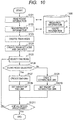
- FIG. 10 shows the procedure of generating the network model in S202.
- the network creation unit 1004 reads the route information 4 stored in the storage unit 1100.
- the network creation unit 1004 reads the resource information 3 stored in the storage unit 1100.
- the network creation unit 1004 generates the train node indicating each train by separating the route information read in S121 to the train, and allocates the attribute of the train extracted from the route information to the train set node of the train.
- the details of the train node and the attributes allocated to the train node are represented by the network model of FIG. 6 .
- the identification information used as the name of the train on the route information is added as the one for the node of the subject train.
- the network creation unit 1004 creates the train set node and the end node based on the resource information read in S122, and adds the identification information and attributes of the node to the respective nodes.
- the details of the nodes are the same as those represented by the network model shown in FIG. 6 .
- the network creation unit 1004 selects one node from those created in S123 and S124.
- the network creation unit 1004 determines whether the node selected in S125 is the end node. If it is the end node, the process proceeds to S127 for generating the end link. If it is not the end node, the process proceeds to S129 for generating the connection link.
- the network creation unit 1004 creates the end link as described below.
- the end link is created from the node selected in S125 to the train set node with the same terminal station as the "terminal station in the original plan" as one of attributes of the selected node (end link 1). Furthermore, the end link is generated from the node selected in S125 towards the rest of the train set nodes (end link 2).
- each weight to the end links 1 and 2 created in S127 is set.
- the weight value to the end link 1 is set with more ease in creation of the resource management plan than the end link 2.
- the network creation unit 1004 generates the connection link from the node selected in S125 towards the node which enables the connection based on comparison between the starting station and the start time, and the terminal station and termination time.
- the detailed explanation is the same as the one described referring to the network model shown in FIG. 6 .
- the network creation unit 1004 sets the weight to the connection link created in S129. If the two nodes connected through the link are sequentially allocated to the same train set in the original plan, the weight values are set so that they are selected with more ease than the other link connected to at least one of the two nodes in creation of the resource management plan.
- the network creation unit 1004 determines whether all the nodes created in S123 and S124 are processed in S127 to S128 or S129 to S1210. If all the nodes are processed, a series of processes are finished. If they are not processed, the process proceeds to S125.
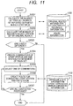
- the merge candidate determination unit 1005 reads the operation information 2, the resource information 3, and the route information 4 from the storage unit 1100, and calculates the number of train sets (deposit number) X at each station set as the management completion station. If the runnable track and the allocatable train vary depending on the vehicle type, the value is calculated for each vehicle type so that the subsequent process will be executed for each vehicle type individually.
- the merge candidate determination unit 1005 calculates the deposit number Y at each station in the original plan. Specifically, the original route information 1 is read from the storage unit 1100 so as to calculate the deposit number at each station.
- the allocated route is not continuous upon determination of the management completion station of each train set, that is, among trains allocated in series to the same train set, the terminal station of the train allocated earlier and the starting station of the train allocated later are different, or the train allocated later starts earlier than the termination time of the train allocated earlier, the train set including up to the train which keeps continuity may be validated.
- the management completion station is set as the last terminal station for the group of validated trains among those allocated to the train set.
- the merge candidate determination unit 1005 determines whether or not the deposit number X calculated in S1301 is different from the deposit number Y calculated in S1302. If it is determined that both values are different, the process executes S1304. If both values are equal, the process ends.
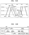
- the merge candidate determination unit 1005 generates the candidates in the resource merging section. For example, in the railroad application, combinations of the starting station and terminal station among the stations which allow the merge train to run. Generation of the candidates for the merging section may vary depending on whether the management completion station for each train set conforms to the original plan, or whether the deposit number of each management completion station conforms to the original plan. Assuming that the plan shown in FIG. 3 is designated as the original plan, the cases of suspending the train 3 (train line 61, horizontal bar 63) and the train 4 (train line 62, horizontal bar 64) will be described referring to FIG. 12 .
- the management completion station (S1) of the operation information 2 read from the storage unit in S1301 for each train set is compared with the management completion station (S2) in the original plan so as to detect the different train set.
- the station S1 is designated as the starting station of the merging section
- the station S2 is designated as the terminal station of the merging section, and a combination of the starting station and terminal station of the merging section is made.
- the management completion station is kept unchanged, if the suspension of the service is included in the route, the station where the suspension starts is designated as the starting station of the merging section, and the station where the suspension ends is designated as the terminal station of the merging section. The combination of the starting and terminal stations of the merging section is added.
- FIGS. 12A and 12B An example of the service suspension will be described referring to FIGS. 12A and 12B .
- Operations of the trains 3 and 4 are suspended so that the management of the train set A is completed at the train 1, which is changed from the train 8.
- the station A is designated as the terminal station of the trains 8 and 1, and the management completion station is not changed.
- the train set C the train to run upon start of the management is suspended, and accordingly, it cannot be pulled out of the car depot.
- the management completion station is changed from the station C as the terminal station of the train 10 to the station A.
- the combination of the station A as the starting station and the station C as the terminal station of the merging section is made as one of candidates of the merging section.
- the route of the train set A includes suspension of the operation although the management completion station is not changed.
- the combination is added as one of the candidates of the merging section.
- the group of stations for setting the deposit number to 0 is generated using the station having the deposit number calculated in S1301 different from the one calculated in S1302.
- the station having the deposit number larger than the original plan is set as the starting station of the merging section, and the station having the deposit number smaller than the original plan is designated as the terminal station of the merging section.
- combination of the starting station and the terminal station of the merging section is made.
- the suspended starting station is designated as the starting station of the merging section, and the suspended terminal station is designated as the terminal station of the merging section.
- the combination of the starting station and the terminal station of the merging section is added.
- the management completion station of the train set C is changed from the station C to the station A.
- the deposit number of the station A is increased to be larger than that of the original plan by 1, and the deposit number of the station C is decreased to be smaller than that of the original plan by 1.
- the combination of the station A as the starting station of the merging section and the station C as the terminal station of the merging section is made as one of candidates of the merging section.
- the route of the train set A includes suspension of the operation although the management completion station is unchanged.
- the combination of the station A as the starting station of the suspended section designated as the starting station of the merging section, and the station C as the terminal station of the suspended section designated as the terminal station of the merging section is added as one of candidates of the merging section.
- the merge candidate determination unit 1005 selects one unprocessed combination from those of the starting station and terminal station of the merging section which are generated in S1304.
- the merge candidate determination unit 1005 reads the mergeable site information 5 stored in the storage unit 1100, and creates the route which designates the starting station selected in S1305 to allow merging as the starting point, and designates the terminal station selected in S1305 to allow separation as the arrival point.
- the determination whether the station allows merging may be made by obtaining a mergeable site 52 with the track under the processing as the search key of the target track 51 using the mergeable site information 5. The determination is made based on whether or not the obtained result includes the station in the process.
- the determination whether the station allows separation may be made by obtaining a separable site 53 by taking the track under the processing as the search key of the target track 51. The determination is made based on whether the obtained result includes the station in the process.
- the route may be selected as described below in accordance with the condition needed to be considered upon insertion of the merge train.
- the route which contains the smallest numbers of trains is selected, and such route is only generated.
- the route which contains maximum numbers of trains is selected, and such route is only created.
- each route is generated to contain only the train of the same allocable type in the same route.
- the generated route is stored in the merge candidate information 6 ( FIG. 5 ) of the storage unit 1100. Specifically, the combination of the starting station and terminal station of the merging section selected in S1305 is stored in the merging section 61 of the merge candidate information 6. The train IDs or train names of all the trains contained in the generated route are stored in the merge candidate 62. A mergeable number 63 stores the number of times that the same combination overlaps among the group of combinations generated in S1304.
- the example shown in FIG. 12 shows two combinations each defining the "station A" as the starting station, and the "station C" as the terminal station of the merging section.
- the route of the run of the section between the station A and station C has three patterns based on the operation information shown in FIG. 12A , that is, route I: train 5, route II: train 5, train 6, train 10, route III: train 5, train 8, train 10, respectively.
- the both routes II and III include the route I which has the smallest number of trains.
- the route including the "train 5" is generated.
- the merge candidate information 6 stores "station A to station C" for the merging section 61, "train 5" for the merge candidate 62, and "2" for the mergeable number 63.
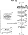
- the plan creation unit 1007 temporarily deletes the end link with the weight larger than the fixed value from the network model generated by a series of the processes S201 to S205 for the purpose of enhancing the capability of creating the plan so that the terminal station of the route for each train set becomes the same as that of the original plan.
- the plan creation unit 1007 searches the round route (specifically, the route which returns the start node without passing any node except the starting node twice or more) based on the network model as a result of the process in S1401.
- the round route to be generated herein has a closed circuit starting from the train set node to the train set node through the end node as shown by the network model.
- the plan creation unit 1007 generates the constraint condition for searching the solution in subsequent step S1404 onward based on the mergeable site information 5 and the merge candidate information 6 stored in the storage unit 1100.
- An object function means to obtain the set of round routes for minimizing the sum total of the weight.
- the condition (1) represents that the respective nodes are only contained in one round route at most in the set of round routes as the solution
- the condition (2) represents that the number of time that the node other than the merge train appears is equal to the number of nodes other than the merge train. Combination of the conditions (1) and (2) allows the node other than the merge train is only contained in one round route only once in the set of the round routes as the solution. The node of the merge train is not contained in the round route, or may be contained therein only once.
- the condition (3) represents that the number of existing round routes contained in the set of the round routes as the solution is equal to the number of the train sets. There may be the case that the round route which contains two or more train set nodes is generated in S1404. The condition (3) has to be established so as not to select such round route.
- the condition (4) is the one (separate-merge condition) for carrying out the merging and separating works of the resource at the available location.
- the separate-merge condition is considered to generate the route of the merge candidate, having mergeable site as the starting point, and the separable site as the end point.
- the process is intended to limit unwanted separation and merging by sequentially allocating the merge train node to the same route. Therefore, depending on the route for allocating the original train node as the merging counterpart, unwanted separation and merging may occur. If the merge candidate has the pattern "train 5, train 6, train 10", the nodes which represent those trains 5, 6 and 10 are reproduced to generate the merge train node so as to generate the link which allows connection of the merge train nodes of 5, 6 and 10 in series.
- train nodes 5, 6 and 10 there is no limitation among the train nodes 5, 6 and 10.
- those merge train nodes 5, 6 and 10 are allocated to the same route (route I), that is, allocated to the same train set without causing separation and merging on the way.
- the original train may take the route of such pattern as "train nodes 5, 7 and 9".
- the merging counterpart is separated at the terminal station of the train 5 so as to run as the train 6. It is merged with another train set, and the train 6 runs as the merge train.
- the original train node as the merging counterpart is limited under the condition (4).
- the merge train node has to be sequentially allocated to the same route.
- the train node as the merging counterpart only when the merge train node is merged, all the nodes of the train contained in the merge candidate are allocated to the same route. For instance, in the aforementioned example, only when the pattern "merge train nodes 5, 6, 10" is contained in the round route of the solution, the pattern "train nodes 5, 6, 10" has to be contained in the round route of the solution.
- the description how the condition (4) is expressed will be explained hereinafter.
- the left term of the subtraction under the condition (4) denotes the node representing the one other than the merge train among those representing the train contained in the kth merge candidate, and the number of nodes contained in the round route j.
- the right term of the subtraction under the condition (4) is the one representing the merge train among those representing the train contained in the kth merge candidate, and the number of nodes contained in the round route 1.
- the node representing the train contained in the merge candidate denotes the merge train node created by the merge candidate incorporating unit 1006 based on the merge candidate 62 of the merge candidate information 6, and the train node as the source.
- the right term of the subtraction takes the value of 0 or Npk.
- the nodes contained in the merge candidate no link is generated between the merge train node and the train node as the source.
- the number of nodes contained in the round route is up to Npk at the maximum. Therefore, the left term takes the value equal to or larger than 0, and equal to or smaller than Npk. If the round route 1 does not contain the merge train, that is, the right term in the subtraction takes 0, the condition (4) is established irrespective of the value of the left term of the subtraction.
- the condition (4) is established only when the left term value of the subtraction is Npk, that is, the round route j contains all the train nodes of merge candidates.
- the Npk denotes the number of the "trains" contained in the kth merge candidate. For example, as the merge candidate of the record 64 shown in FIG. 5 includes only the "train 5", the Npk has the value of "1". If the merge candidate pattern has the "trains 5, 6, 10", its value is 3.
- condition to allocate one train set only to one route is added.
- the network model according to the invention represents the train set as the node, such condition is contained in the one as described above.
- Each of the round routes contained in the resultant set of the round routes may be the route allocated to the train set represented by the train set node contained in the round route.
- the plan creation unit 1007 determines whether the solution is obtained by searching in S1404. If the solution is obtained, the process proceeds to S1406. If it is not obtained, the process proceeds to S1407 for carrying out the determination.
- the plan creation unit 1007 stores the solution obtained in S1404 in the storage unit 1100 as the candidate for the resource management plan. At this time, the plan creation unit 1007 creates the candidate resource management plan by allocating the respective round routes contained in the solution obtained in S1404 to the train set corresponding to the train set node contained in the round route. If the solution contains the merge train node, the plan creation unit 1007 extracts the train node as the counterpart of the merge train node, and the merge train node, makes a comparison between the extracted train and the merge train with respect to the arrival time at the station, and calculates the position at which the respective trains (extracted train and merge train) are merged (the numbers of vehicles from start to end position).
- the vehicle position is set at the forward position in the order of earlier arrival time. If the running direction after merging is changed, the vehicle position is set at the forward vehicle position in the order of later arrival time.
- the plan creation unit 1007 determines whether the end link with the weight larger than the fixed value is contained in the solution obtained in S1404. If it is contained, the process proceeds to S1408. If it is not contained, the process ends.
- the fixed value of the weight is assumed to have the same value as the fixed value used in S1401. The process is intended to determine whether the solution contains the train set with the terminal station of the route different from that of the original plan.
- plan creation unit 1007 returns the link deleted in S1401 to the network model, and the process proceeds to S1402.
- the resource management plan which contains the merge train is created to conform the management completion site or the deposit number to the original plan.
- the deadheading train is set to create the resource management plan without changing the management completion site or the deposit number of the original plan. This embodiment describes the feature different from that of the first embodiment.
- FIG. 16 is a detailed flow of S203 "determination of merge candidate" according to the first embodiment.
- the process steps from S1301 to S1305 are the same as those described in the first embodiment.
- the merge candidate determination unit 1005 produces the deadhead train that leaves the candidate starting site of the merging section selected in S1305, and arrives at the terminal site as the terminal station, and passes through all the intermediate stations, and stores the information in the merge candidate information 6 of the storage unit 1100.
- the process executed in S1307 is the same as the one described in the first embodiment.
- step S203 according to the first embodiment is replaced with the aforementioned flow. If the merge candidate is the deadhead train upon incorporating the merge candidate to the network model in S205, it is added to the network model as the deadhead train node, and the link with the other node is generated in consideration of the link connection between the starting station and terminal station of the train.
- the first embodiment is configured to create the merge candidate based on the management completion site.
- a third embodiment configured to accept designation of the starting site and terminal site of the merge section from the user, and create the merge candidate for realizing the accepted merge section.
- the features different from those of the first embodiment will be described.
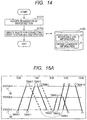
- FIG. 14 shows a detailed flow of S203 "determination of merge candidate" according to the first embodiment.
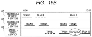
- the merge candidate determination unit 1005 accepts inputs of the starting site and the terminal site of the merging section via the input unit 1201 from the user. At this time, based on the operation schedule read in S201, and the route information and resource information read in S121 and S122, charts of the operation schedule and allocation of the train as shown in FIG. 15 are displayed.
- the configuration shown in FIG. 15 is the same as the one shown in FIG. 9 .
- FIG. 15 displays the deposit numbers at the respective stations (65, 66 of FIG. 15A ), and the management completion site for the respective train sets (67, 68, 69 of FIG. 15B ).
- the merge candidate determination unit 1005 generates the route as the merge candidate based on the starting site and the terminal site of the merging section accepted in S1701.
- the process is the same as the one executed in S1306 of the first embodiment.
- the process step S203 of the first embodiment is replaced with the aforementioned flow. Any other process steps are executed in the similar way to the first embodiment, enabling creation of the resource management plan.
- the first embodiment is configured to create the resource management plan without considering the order of merging the multiple resources.
- a fourth embodiment shows an example of creating substantially practical resource management plan by considering the merging order derived from the arriving order of the train.
- FIG. 17 is a detailed flow of S206 "creation of resource management plan" according to the first embodiment. Steps in S1401 to S1404 are the same as those described in the first embodiment.
- plan creation unit 1007 executes the following processes with respect to the merge train contained in the solution obtained in S1404.
- the merge train set in the original plan As for the merge train set in the original plan, a comparison is made between the train sets to be merged with each other with respect to the arrival time, and the number corresponding to early or late timing at the train set position in accordance with the order from the earlier arriving is temporarily allocated.
- the train set position temporarily allocated is compared with the train set position in the original plan. If those positions are different, it is determined whether the subject train can be replaced at the merge station based on a shunting information 7 stored in the storage unit 1100. If it cannot be interchanged, the temporarily allocated train set position is set as one of the subject train.
- step S206 of the first embodiment is replaced with the aforementioned flow.
- the rest of the process steps are executed in the similar way to the first embodiment so as to allow creation of the resource management plan.
Landscapes
- Engineering & Computer Science (AREA)
- Business, Economics & Management (AREA)
- Entrepreneurship & Innovation (AREA)
- Strategic Management (AREA)
- Economics (AREA)
- Human Resources & Organizations (AREA)
- Marketing (AREA)
- Tourism & Hospitality (AREA)
- Educational Administration (AREA)
- Development Economics (AREA)
- Mechanical Engineering (AREA)
- Operations Research (AREA)
- Quality & Reliability (AREA)
- Game Theory and Decision Science (AREA)
- Physics & Mathematics (AREA)
- General Business, Economics & Management (AREA)
- General Physics & Mathematics (AREA)
- Theoretical Computer Science (AREA)
- Train Traffic Observation, Control, And Security (AREA)
- Management, Administration, Business Operations System, And Electronic Commerce (AREA)
Description
- The present invention relates to a resource management plan creation device, a resource management plan creation method, and a resource management plan creation program. More specifically, the present invention relates to technique that enables to create the resource management plan for managing the resource, for example, a moving medium (vehicle and airframe), crew members in transport services, especially railroad and aviation industries in consideration of the management completion site of the resource.
- In transport service such as railroad and aviation, a maintenance work plan of resources (moving media) used for operation and an operation plan for crews are considered in parallel with the management of an operation schedule. For example, as for a railroad, a period of vehicular inspection is legally prescribed so that inspection work is required to be regularly executed to adhere to the inspection period while efficiently allocating the vehicle to the train. The continuous duty periods and work hours of the crew members are legally prescribed that have to be posted to the duty on board while following the legal approach. Such a plan in consideration of the resource management will be hereinafter referred to as "resource management plan".
- In the resource management plan for the railroad, a vehicle allocated to the train is required to be selected out of massive combination, considering a characteristic of an individual vehicle such as a type and the performance, the timing of a shuttle at a station, the time of return to a car depot for inspection and the like. It is manually difficult work. Likewise, in the crew member management plan, the crew member to work on board of the train is required to be selected out of massive combination, considering each characteristic of the crew member such as working conditions and the duty histories, a time taken for transfer or transfer timing, and break time. However, the creation of the resource management plan for the railroad is not sufficiently systematized with respect to the vehicle and the crew members. For this reason, the manual creation relies on experiences of experts.
- Various ideas for automatically creating the resource management plan have been proposed. For example,
Patent Document 1 and Non-PatentDocument 1 provide a means to recreate a resource management plan also in consideration of an inspection period based on a train timetable changed to recover from disruptions.Patent Document 2 provides a means to find a location in which unscheduled inspection work can be executed based on inquiry about the connection of trains, and to create a resource management plan into which an extraordinary inspection work is inserted.Patent Document 3 provides a means to accept a desirable pattern from a user about a shuttle of a train and a vehicle allocated to a train, and to create the resource management plan in consideration of the intention of a user about connection of trains. -
- Patent Document 1:
JP-A-2010-58771 - Patent Document 2:
JP-A-2005-259052 - Patent Document 3:
JP-A-2003-154939 - Non-Patent Document 1: "Freight Train Locomotive Rescheduling Problem after Disruptions" by Keisuke Sato and Naoto Fukumura, IPSJ SIG Notes 2009 (19), 141-144, 2009-02-26 Furthermore the Patent Document
JP-2010-285053 A - When a resource management plan is created, it is important not only to meet characteristics of vehicles and crew members, and an operation schedule but to secure the regularity of management (so called management pattern). For example, in case of the railroad, a vehicle expected to have large-scale inspection is stored in a car depot all day before the inspection as a spare vehicle, and a period for a deposit as a spare vehicle is intentionally considered so as to equalize travel distances and running days among multiple vehicles. Such regularity is an important element not only to execute periodic maintenance work but to enable usual maintenance work and usual vehicle storage work on the spot. Likewise, for the crew member, there is a management pattern intended to regularly allocate the day off and to equalize the time for duty on board.
- In order to change the plan during disruptions, it is important to retain the location where the operation of the resource is completed (deposit site) in a day, or the number of resources intended to have the management completed at least on the same site, which are specified in the original plan so as not to disturb the management pattern next day onward. For example, in the case of the railroad, the vehicle having its management of the day completed is stored in the station yard at which the management of the vehicle is completed or in the adjacent car depot so as to start the management from the site on the following day. If the operational schedule is disrupted, the station where the management of the vehicle is completed (management completion site) is changed. The train different from the one specified in the original plan has to be allocated to the vehicle on the next day, thus causing interruption with the management pattern and omission of executing the inspection work. In order to prevent the aforementioned problem, the railroad operator takes the measure to return the vehicle as a deadhead train having the management completion station changed to the station as specified in the original plan if necessary, thus causing lower resource management efficiency.
- The technique as disclosed in the aforementioned documents is intended to create the management plan, aiming at efficient management in the time range to be planed, however, the conditions for the deposit site are not considered.
- It is an object of the present invention to provide a resource management plan creation device, method, and program thereof without changing the management completion site from the original plan.
- Preferably, a resource management plan creation device is configured to be realized by a computer which includes a storage unit for storing information, an output unit for outputting the information, an input unit for inputting the information, and a processing unit for executing a program, wherein the storage unit stores operation schedule information of a transport service, and wherein the processing unit executes the program to provide: an operation schedule read unit for reading the operation schedule information of the transport service preliminarily stored in the storage unit, a network creation unit which creates a network model for transport routes by generating a node having at least a starting site, a start time, a terminal site and a termination time of each transport route as attributes, and generating each path for connecting nodes representing each transport route that allows a continuous operation using a same resource based on the attributes of the respective nodes with respect to multiple transport routes contained in the operation schedule based on the operation schedule information, generates a management starting node with at least information for identifying a management starting site of each resource and a vehicle as the attributes, and a management completion node with at least information for identifying each management completion site and each resource as the attributes, generates each path for connecting the nodes representing each transport route that allows allocation of the resource represented by the management starting node, and the management starting node based on the attributes of the management starting node and the other node, generates each path for connecting the nodes which have values of the attributes of the management completion site of the management completion node accorded with those of the terminal site of the other node, and generates each path for connecting the management starting node and the management completion node having the same resource identification information as the attribute, which are added to the generated network model, a merge candidate determination unit for extracting transport routes as a candidate to which multiple resources are allocated to achieve a condition that the management completion site of each resource is not changed from an original plan based on the operation schedule information, a merge candidate incorporating unit which adds paths for connecting each merge train node and the other nodes to the network model by generating each merge node through reproduction of the node representing the transport route which allows allocation of the multiple resources based on the attributes of the merge nodes and other nodes which constitute the network model, and a plan creation unit which extracts a path combination constituting multiple paths capable of allocating one resource to the respective nodes other than the merge nodes that forms the network model, and allocating the resource to each of the multiple paths that form the extracted combination so as to create and output the resource management plan that meets a condition that does not change management completion sites from the original plan.
- Preferably, a resource management plan creation method is realized by a computer which includes a storage unit for storing operation schedule information of a transport service, an output unit for outputting information, an input unit for inputting the information, and a processing unit for executing a program. Through an operation of the processing unit to execute the program, the method includes the steps of reading the operation schedule information stored in the storage unit, based on the operation schedule with respect to each of multiple transport routes contained in the operation schedule, providing a network model for transport routes by generating a node with at least a starting site, a start time, a terminal site and termination time of each transport route as attributes, and generating each path for connecting the nodes representing each transport route that allows continuous operation using the same resource based on the attributes of the respective nodes, generating a management starting node with at least information for identifying a management starting site of each resource and a vehicle, and a management completion node with at least information for identifying each management completion site and each resource as the attributes, generating each path for connecting the nodes representing each transport route that allows allocation of the resource represented by the management starting node and the management starting node, generating each path for connecting the nodes which have values of the attributes of the management completion node at the management completion site accorded with those of the other node at a completion site, and generating each path for connecting the management starting node and the management completion node each having the same resource identification information as the attribute, which are added to the generated network model, and extracting transport routes as a candidate for allocating multiple resources to achieve a condition that does not change the management completion site of each resource from the original plan based on the operation schedule information, generating each merge node by reproducing the node representing each transport route that allows allocation of multiple resources, adding paths for connecting each merge train node and the other nodes based on the attributes of the merge node and the other nodes constituting the network model, extracting a path combination that constitutes multiple paths that allow allocation of one resource to the nodes other than the merge nodes constituting the network model from the network model, and creating and outputting the resource management plan to meet the condition that does not change the management completion site from the original plan by allocating the resource to each of the multiple paths constituting the combination.
- The program for creating the resource management plan according to the present invention is configured as a program executable on a computer to create the resource management plan.
- The present invention allows creation of the management plan without changing the resource management completion site or the number of resources which stay in the management completion site from the original plan.
-
-
FIG. 1 shows a structure of a resource management plan creation device according to an embodiment of the present invention. -
FIG. 2 is a flowchart showing a basic procedure for processing the resource management plan creation device. -
FIG. 3A shows an example of a train operation schedule. -
FIG. 3B shows an example of train allocation to the train sets of the operation schedule of the train. -
FIG. 4 shows a configuration of the mergeable site information record and an example of data that belong to the record. -
FIG. 5 shows a configuration of a merge candidate information record and an example of data that belong to the record. -
FIG. 6 shows an example of a network model representing a management plan. -
FIG. 7 shows an example of a network model representing the management plan to which the merge trains are added. -
FIG. 8 shows an example of solution for the management plan represented by the network model. -
FIG. 9 shows an example of an output screen of the resource management plan creation device. -
FIG. 10 is a flowchart showing a procedure for creating the network model. -
FIG. 11 is a flowchart showing a procedure for determining the merge candidate. -
FIG. 12A shows an example of suspension of the operation. -
FIG. 12B shows an example of suspension of the operation. -
FIG. 13 is a flowchart showing a procedure for creating the management plan. -
FIG. 14 is a flowchart showing a procedure for determining the merge candidate. -
FIG. 15A shows an example of the train operation schedule. -
FIG. 15B shows an example of the train allocation to the respective train sets according to the train operation schedule. -
FIG. 16 is a flowchart showing a procedure for determining the merge candidate. -
FIG. 17 is a flowchart showing a procedure for creating the management plan. - Embodiments according to the present invention will be described referring to the drawings, taking vehicular management in a railroad application as an example.
-
FIG. 1 is a block diagram showing an example of the configuration of a resource management plan creation device. - A resource management
plan creation device 1000 is configured by a computer which includes amemory 1001, astorage unit 1100, adisplay unit 1200, aninput unit 1201, a processing unit (CPU) 1202, acommunication unit 1203, and adata bus 1204 that connects those elements. The resource managementplan creation device 1000 is connected to an external terminal device and the like via a communication network. - The
display unit 1200 is an output unit such as a liquid crystal display for visualizing the information, and configured to display the information to a user such as a state and a result of the process executed by the resource managementplan creation device 1000. Theinput unit 1201 is a device such as a keyboard and a mouse configured to accept the input from the user for inputting an instruction to the computer. Theprocessing unit 1202 executes various programs stored in thememory 1001. Thecommunication unit 1203 exchanges various data and commands with another device via a local area network (LAN) and others. Thestorage unit 1100 stores various data for the resource managementplan creation device 1000 to execute the process. Thememory 1001 holdsvarious programs 1002 and temporary data for the resource managementplan creation device 1000 to execute the process. - The
storage unit 1100 storesoriginal route information 1,operation information 2,resource information 3,route information 4,mergeable site information 5 and mergecandidate information 6. - The
memory 1001 stores theprogram 1002 which is executed by theprocessing unit 1202 to realize various function units including an operation schedule readunit 1003, anetwork creation unit 1004, a mergecandidate determination unit 1005, a mergecandidate incorporating unit 1006, and aplan creation unit 1007. - The operation schedule read
unit 1003 reads theoperation information 2 stored in thestorage unit 1100. Thenetwork creation unit 1004 creates a network model representing the resource management plan based on the operation information read by the operation schedule readunit 1003. The network model will be described in detail later referring toFIG. 6 . - The merge
candidate determination unit 1005 calculates the management completion station for each resource based on the operation information read by the operation schedule readunit 1003, and determines a route as the candidate to which multiple resources are allocated based on the calculated result. - The merge
candidate incorporating unit 1006 changes the network model created by thenetwork creation unit 1004 based on the route determined by the mergecandidate determination unit 1005 as being the candidate to which the multiple resources are allocated. The changed network model will be described in detail referring toFIG. 7 . - The
plan creation unit 1007 generates constraint conditions based on the network model which has been created by thenetwork creation unit 1004 and changed by the mergecandidate incorporating unit 1006, creates the resource management plan to meet the resultant constraint conditions, and present the created resource management plan to the user via thedisplay unit 1200. -
FIG. 2 is a flowchart showing a basic procedure for processing operations of the resource managementplan creation device 1000. - An outline of the operation procedure will be described.
- The operation schedule read
unit 1003 reads theoperation information 2 stored in the storage unit 1100 (S201). Thenetwork creation unit 1004 creates the network model representing the management plan of the resource such as the vehicle based on the operation schedule read by the operation schedule read unit 1003 (S202). The network model to be generated will be described in detail referring toFIG. 6 , and the method of generating the network model will be described in detail referring toFIG. 10 . - The merge
candidate determination unit 1005 determines the routes (hereinafter referred to as a merge candidate) as the candidates to which multiple resources are allocated based on the operation schedule read in S201 and themergeable site information 5 stored in the storage unit 1100 (S203). In the case of railroad, for example, the determination is made with respect to the train as the merge train candidate. The merge train represents the one formed by connecting multiple train sets so as to run as the single train. The train set represents a set of multiple vehicles allocated to the train. The merge candidate determination method will be described in detail referring toFIG. 11 . - The merge
candidate determination unit 1005 determines whether there is the trains determined as the merge candidates in S203. If there is at least one candidate, the process S205 is executed for incorporating the merge candidates to the network model created in S202. If there is no merge candidate, the process S206 is executed for creating the resource management plan (S204). - The merge
candidate incorporating unit 1006 adds nodes representing the trains as the merge candidates determined in S203 and links to the network model created in S202 (S205). The network model to which the merge candidates are added will be described in detail referring toFIG. 7 . - The
plan creation unit 1007 generates a mathematical model formulated as the vehicle routing problem based on the network model created in a series of processes from S201 to S205, and creates the resource management plan which meets conditions represented by the mathematical model (S206). The mathematical model to be created and the plan creation procedure will be described in detail referring toFIG. 13 . Theplan creation unit 1007 displays the resultant resource management plan created in S206 on the display unit 1200 (S207) for informing the user. If the multiple plans are created in S206, all the resultant plans will be displayed. - Various types of
information 1 to 6 treated in the embodiment will be described, and therespective processing units 1003 to 1007 of the resource managementplan creation device 1000 will be described in detail. - The
original route information 1 relates to the route which has been planned before starting the operation, and the item is formed by adding the starting station and terminal station for the respective trains to that of thesubsequent route information 4. - The
operation information 2 represents the one which defines the route for each minimum unit of the transport service. For example, the train is the minimum unit of the transport service in the railroad, which is defined by the station at which the train stops or bypasses between the starting station and the terminal station, the arrival-departure time or passing time at each station. - The
resource information 3 defines the resource used for the transport service. For example, the resource information of the railroad includes the one about the vehicle and the crew. For example, the information that defines the vehicle is represented by the vehicle name or identification number for uniquely identifying the vehicle, the maintenance work (inspection and cleaning) expected to be carried out on the day of operation, the time at which the maintenance work may be carried out, the maintenance work site, and the route identification number for uniquely identifying the transport service (corresponding to the train in the case of railroad), which is allocated to the vehicle. - The
route information 4 defines the order of executing the minimum units of the transport service by the single resource. In the case of railroad, the route information is formed by listing the train information allocated to the single train set in consideration of turn back operation, and pull-in/pull-out of the car depot (FIG. 3A ). The train information represents the train name or the train ID for uniquely identifying the train. For example,FIG. 3B represents allocation of trains to three train sets. Specifically, the single train set is allocated to thetrains trains trains - The
mergeable site information 5 defines the site which allows the work of merging or separating the multiple resources. For example, in the case of railroad, the mergeable site information defines the station that allows merging or separation of the multiple train sets, or the station linked to the car depot.FIG. 4 shows an example of themergeable site information 5 in the case of railroad, for example. Atarget track 51 stores the ID or the track name for uniquely identifying the track to be defined. Amergeable site 52 denotes the station which belongs to the track identified by thetarget track 51, and stores the ID or the station name for uniquely identifying the station which allows execution of the merging work. Aseparable site 53 denotes the station that belongs to the track identified by thetarget track 51, and stores the ID or the station name for uniquely identifying the station that allows the separation work. For example, records 54 indicate that the stations A and C among those belong to the track A allow the merging work, and the station C allows the separation work. - The
merge candidate information 6 stores the route determined as the merge candidate by the mergecandidate determination unit 1005, or the preliminarily determined merge candidate, if any. In the case of railroad, it is the information for defining the train as the merge candidate.FIG. 5 shows an example of the merge candidate information. A mergingsection 61 stores the section between stations, on which the train runs as the merge train. Amerge candidate 62 stores the train as the merge candidate. Amergeable number 63 stores the maximum number of the mergeable train sets as the merge train. For example, therecord 64 represents that the maximum of two additional train sets can be merged with the original train set to form thetrain 5 which may run on the merging section between stations A and C. - The relevant operation of the embodiment will be described referring to
FIGS. 3A and 3B . The model of the resource management plan will be described referring toFIG. 6 . Then each function and operation of the respective processing units of the resourcemanagement creation device 1000 will be described in detail referring toFIGS. 7 to 13 . The embodiment assumes the work for rescheduling the vehicle management which is carried out when the operation of trains disrupts. The rescheduling for the vehicle management is carried out when the accident or failure of the vehicle unexpectedly change the train operation schedule by changing the allocation of the vehicle to the train in accordance with the changed operation schedule. A means for changing the allocation of the vehicle includes a means for changing the train allocated at the terminal station, a means for temporarily pulling out the spare train that stays in the car depot, and a means for temporarily storing the vehicle in the car depot. The vehicle is required by law to be regularly inspected in accordance with the travel distances and running days. In rescheduling the vehicle management, the vehicle allocation is changed by combining the aforementioned means in consideration of the inspection which is determined so as not to exceed the inspection cycle. -
FIG. 3 shows charts used in the transport service of railroad and data used in this embodiment as the example. -
FIG. 3A shows an example of the operation schedule of trains. The operation schedule of trains is generated based on theoperation information 2. Avertical axis 31 inFIG. 3A denotes stations, and ahorizontal axis 32 denotes time. One train is represented by drawing a line from a starting station to a terminal station of the train with the passage of time (referred to as a train line). For example, athick line 33 represents one train that leaves the station C about six o'clock and arrives at the station A about six thirty. - A
line segment 34 that connects two train lines represents a group of trains allocated to one train set. For example, referring to an example shown inFIG. 3B , thetrains sign 35 denotes timing at which the train set is pulled out of the car depot. For example, thesign 35 shows that the train set is pulled out of the car depot adjacent to the station C in accordance with departure of thetrain 1. As asign 36 shows, a mark represented by "Δ" represents timing at which the train set is stored in the car depot. For example, thesign 36 shows that after thetrain 6 arrives, the train set allocated to thevehicle 6 is stored is stored in the car depot adjacent to the station A. -
FIG. 3B shows the allocation of the trains to the respective train sets. The train allocation is made based on theresource information 3 and theroute information 4.FIG. 3B is expressed with ahorizontal axis 41, atrain set name 42, andallocation information 43. - The
axis 41 denotes time, and thetrain set name 42 denotes the name for uniquely identifying the train set. Theallocation information 43 denotes the allocation of the vehicle to the train set indicated by thetrain set 42. Each train to be allocated is represented by one horizontal bar (for example, a horizontal bar 44), and a train name (for example, train name 45) is put aside the horizontal bar. If the train set is expected to have the maintenance work such as cleaning and inspection, the sign indicating the expected work is displayed. For example, asign 46 represents that the train set C is expected to have the maintenance work, specifically, an inspection A after running as thetrain 6. - A series of route information will be described, taking a
record 47 as an example. Therecord 47 denotes a route allocated to the train set C, representing that after it runs as thetrain 3, it then runs as thetrain 6, and after work of the inspection A is done, it runs as thetrain 10.FIG. 3A shows that thetrain 6 is stored in the car depot adjacent to the station A after the run, and thetrain 10 is pulled out of the car depot adjacent to the station A. Therefore, it is known that after the train set C is once stored in the car depot after it runs as thetrains train 10. -
FIG. 6 shows the network model of the resource management plan. In an example shown inFIG. 6 , some links are omitted for simplicity.FIG. 6 shows the network model representing a candidate that can be formed into the route, which includes a train set node, a train node, an end node, a connection link and an end link. - The train set node represents a train set to which the route is allocated. One train set node is set per train set. The train set node has start time in a time zone in which the train set is available, termination time in a time zone in which the train set is available, a position in which the train set is kept standby at operation start time (a station adjacent to the car depot where the train set is kept standby or a station where it is kept standby), a starting station and a terminal station of the route in the original plan as attributes.
- The train node represents a train included in the operation schedule. One train node is set per one train. The train node has a starting station, a terminal station, start time and termination time of the train as attributes.
- The end node represents an end of the route. One end node is set per one train set. The end node has a train set name or train set ID for uniquely identifying the train set, and a terminal station of the route planned in the original plan as attributes. For example, the
end node 61 represents an end of the route of the train set A. In the example shown inFIG. 3B , thetrain 8 is the end of the route of the train set A in the original plan and in the example as shown inFIG. 3A , thetrain 8 arrives at the station A. Therefore, a value of an attribute of the terminal station of theend node 61 is the station A. - The connection link means a directed link that links the train nodes, the train set node and the train node, and the train node and the end node, which will be generated as follows.
- The connection link between the train nodes is generated based on a starting station, start time, terminal station, and termination time of the train respectively represented by the train node so that the connection between time and station is established. For example, the
train node 63 represents thetrain 1, and the starting station of it is the station C, a terminal station is the station A, start time is six o'clock, and termination time is six thirty. Thenode 64 represents thetrain 4, and the starting station of it is the station A, a terminal station is the station C, start time is six forty, and termination time is seven five. As the terminal station of thenode 63 is the same as the starting station of thenode 64 by comparison between the two train nodes, the connection is established. Since the termination time of thenode 63 is earlier than the start time of thenode 64, the connection of time is established. Therefore, the connection link from thenode 63 to thenode 64 may be established. Likewise, it is possible to generate the connection link towards the nodes representing thetrain 5, thetrain 3, and thetrain 10 from thenode 63. - A weight that facilitates selection as solution is set to the connection link between the trains continuously allocated to the same train in the original resource management plan compared to any other connection link. For example, the route is created by searching a round route with the smallest weight of the link on the network shown in
FIG. 6 in this embodiment, which will be described in detail later. Therefore, a small weight value is set to the connection link between the trains continuously allocated to the same train set in the original resource management plan. Hereby, a plan having as few changes from the original plan as possible can be acquired. The following description of the weight that facilitates selection as the connection link has the same meaning. - The connection link between the train node and the train set node is generated to establish the connection between time and site based on the starting station, start time, terminal station and termination time represented by the train node, and the start time and end time in the time zone when the train set is available, and the train set position at the start of the management, which are represented by the train set node. For example, the time zone which allows the use of the train set (train set A) represented by the
train set node 62 is 6 o'clock, and the start location is the station C. Accordingly, the connection link is generated from thetrain set node 62 towards the train node representing the train that departs the station C at 6 o'clock or later as the start time. That is, the connection link towards the train nodes representing thetrains - As for the connection link that represents the same allocation as the original resource management plan, the weight that facilitates selection as solution is set compared with any other link.
- The connection link between the train node and the end node is generated from the train node that can be set as a final train of the route toward the end node. The train that can be set as the final train of the route basically means the train that finally arrives at a station adjacent to the car depot or the station yard which allows deposit of the train until the next day. In the meantime, the case that can't be set the train, it is not desirable since the train is redirected to store the vehicle in the car depot.
- In the original plan, the weight that facilitates selection as solution compared with any other link is set to the connection link between the train node and the end node representing the train at the end of the route in the original plan.
- The end link is a link for restricting so that the train set terminates the route at a point scheduled in the original resource management plan. The end link is generated from one end node towards all train set nodes, and sets the weight based on the restriction of the route termination point. That is, a value of the terminal station in the original resource management plan held by the end node and a value of the terminal station in the resource management plan held by the train set node are compared. When those values are the same, the weight value is set to the end link for linking the corresponding end node and the corresponding train set node so as to facilitate selection compared with the end link from the corresponding end node to the other train set node.
- For example, assuming that a link of the smaller weight facilitates selection, the
end node 61 represents an end of the route of the train set A and the terminal station in the original plan is the station A. The node representing the train set A is thetrain set node 62 and a terminal station in the original plan is the station A. Since the terminal station of theend node 61 and the terminal station of thetrain set node 62 are the same, a smaller value than the link extended from theend node 61 to the other train set node is set to the end link for linking theend node 61 and thetrain set node 62. Further, theend node 65 represents an end of the route of the train set B. Since it is indicated byFIG. 3B that thetrain 9 is at the end of the route of the train set B, its terminal station is the station C. Since an end of the route of the train set C is also the station C, a weight of the same value is set to both the end link between theend node 65 and thetrain set node 67 representing the train set B and the end link between theend node 65 and thetrain set node 68 representing the train set C. Even if the train allocated at the end of the route is different from the one in the original resource management plan, the possibility that the trains having the same terminal station are allocated may be increased by setting the weight to the end links as described above. - In the embodiment, if the merge candidate exists, the network model is changed in accordance with the merge candidate based on the aforementioned network model. The resource management plan is then created based on the network model. The procedure for processing performed by the resource management
plan creation device 1000 will be described in detail referring toFIG. 2 . - In S201, the operation schedule read
unit 1003 reads theoperation information 2 stored in thestorage unit 1100. - In S202, the
network creation unit 1004 creates the network model shown inFIG. 6 based on the operation information read in S201. The procedure for creating the network model will be described in detail later referring toFIG. 10 . - In S203, the merge
candidate determination unit 1005 reads themergeable site information 5 stored in thestorage unit 1100 to determine the train as the merge candidate so as to be stored in themerge candidate information 6 of thestorage unit 1100. The determination of the train as the merge candidate will be described in detail later referring toFIG. 11 . - In S204, if it is determined by the merge
candidate determination unit 1005 that the merge candidate exists, the process proceeds to incorporation of the merge candidate (S205). If it is determined that no merge candidate exists, the process proceeds to creation of the resource management plan (S206). - In S205, the merge
candidate incorporating unit 1006 adds the node representing the merge candidate stored in themerge candidate information 6 of thestorage unit 1100 and the link to the network model created in S202. - The method of incorporating the merge candidate to the network model will be described referring to
FIG. 7 . The explanation will be made on the assumption that operation of thetrains candidate determination unit 1005 provides the determination results as shown inFIG. 4 . - As operations of the
trains trains FIG. 6 in S202. In S205, anode 91 representing the train 5 (seeFIG. 4 ) as the merge candidate is detected from the network, and the node is reproduced by the mergeable number. -The resultant nodes are added to the network model. At this time, reproduction of the node means that the same attribute value as that of the node as the connection source is added to the newly generated node. According to the example shown inFIG. 4 , thetrain 5 is mergeable with the maximum of 2 train sets. Therefore, two nodes representing thetrain 5 are reproduced and added to the network model (nodes 92 and 93) as shown inFIG. 7 . - After adding the nodes, the link for connecting the reproduced nodes and the other node is created. There are two methods of creating the link as follows.
- The link is generated to have connection to the same nodes as the ones to which the node as the reproduction source is connected. Referring to
FIG. 7 , for example, thenode 91 is connected to the links including the train node "train 1", train node "train 2", the train set node "train set C" as connection sources, and the links including the train node "train 8", train node "train 7", train node "train 6", and end node "end C" as connection destinations. Similarly, Thenodes node 91 are connected to the links including the train node "train 1", train node "train 2" and train set node "train set C" as connection sources, and the links including the train node "train 8", train node "train 7", train node "train 6" and end node "end C" as connection destinations. - The link having the starting train of merge candidate as the connection destination is generated in the same manner as in the case of the node as the reproduction source. The link having the terminal train as merge candidate as the connection source is generated in the same manner as in the case of the node as the connection source. The link of the trains between the starting and terminal trains is generated so that the link for connecting the merge candidates only exists. For example, assuming that the merge candidate includes "
train 5,train 8, train 10", the link having the reproduced node of thetrain 5 as the connection destination is generated in the same manner as in the case of generating the link having thetrain 5 as the connection destination. The link having the reproduction nodes of thetrain 10 as the connection source is generated in the same manner as in the case of generating the link having thetrain 10 as the connection source. The link having the reproduction node of thetrain 5 as the connection source is generated only towards the reproduction node of thetrain 8. The link having the reproduction node of thetrain 8 as the connection source is generated only towards the reproduction node of thetrain 10. -
FIG. 8 shows an example of the solution of the resource management plan represented by the network model. Referring toFIG. 8 , the management of the train set A is completed after the run as thetrain 1, as a part of themerge train 5, and as thetrain 8. Likewise, the management of the train set C is completed after the run as a part of themerge train 5, as thetrain 6 and as thetrain 10. In S206, theplan creation unit 1007 creates the resource management plan based on the network model obtained through execution of steps S201 to S205. The detailed procedure will be described later referring toFIG. 13 . - In S207, the
plan creation unit 1007 presents the user the plan created in S206.FIG. 9 shows an example of an output screen. Anoutput screen 111 displays achart 112 of the operation schedule and achart 113 of the allocation. The screen is formed by theplan creation unit 1007 and displayed on thedisplay unit 1200. - The
operation schedule chart 112 and theallocation chart 113 may be used in the same manner as described referring toFIGS. 3A and 3B . Referring to the example of the network model shown inFIG. 8 , the train sets A and C are merged with theoriginal train 5, which then runs. Theoperation schedule chart 112 showing the management plan represented by the network model hastrain lines train line 114 corresponding to theoriginal train 5. Referring to theallocation chart 113,line segments train 5 are provided to the sections indicating the allocation of the train to the train sets A, B and C, respectively. Furthermore, a label identifying the number of vehicles of the corresponding train set is provided near the line segment indicating the train. For example, thelabel 120 represents that the train set A runs from the first vehicle to the second vehicle of thetrain 5 among six vehicles. - Generation of the network model in S202, determination of the merge candidate in S203, and creation of the resource management plan in S206 will be described in detail.
-
FIG. 10 shows the procedure of generating the network model in S202. - In S121, the
network creation unit 1004 reads theroute information 4 stored in thestorage unit 1100. - In S122, the
network creation unit 1004 reads theresource information 3 stored in thestorage unit 1100. - In S123, the
network creation unit 1004 generates the train node indicating each train by separating the route information read in S121 to the train, and allocates the attribute of the train extracted from the route information to the train set node of the train. The details of the train node and the attributes allocated to the train node are represented by the network model ofFIG. 6 . In S123, the identification information used as the name of the train on the route information is added as the one for the node of the subject train. - In S124, the
network creation unit 1004 creates the train set node and the end node based on the resource information read in S122, and adds the identification information and attributes of the node to the respective nodes. The details of the nodes (attributes of the node) are the same as those represented by the network model shown inFIG. 6 . - In S125, the
network creation unit 1004 selects one node from those created in S123 and S124. - In S126, the
network creation unit 1004 determines whether the node selected in S125 is the end node. If it is the end node, the process proceeds to S127 for generating the end link. If it is not the end node, the process proceeds to S129 for generating the connection link. - In S127 and S128, the
network creation unit 1004 creates the end link as described below. - In S127, the end link is created from the node selected in S125 to the train set node with the same terminal station as the "terminal station in the original plan" as one of attributes of the selected node (end link 1). Furthermore, the end link is generated from the node selected in S125 towards the rest of the train set nodes (end link 2).
- In S128, each weight to the
end links end link 1 is set with more ease in creation of the resource management plan than theend link 2. - In S129, the
network creation unit 1004 generates the connection link from the node selected in S125 towards the node which enables the connection based on comparison between the starting station and the start time, and the terminal station and termination time. The detailed explanation is the same as the one described referring to the network model shown inFIG. 6 . - In S1210, the
network creation unit 1004 sets the weight to the connection link created in S129. If the two nodes connected through the link are sequentially allocated to the same train set in the original plan, the weight values are set so that they are selected with more ease than the other link connected to at least one of the two nodes in creation of the resource management plan. - In S1211, the
network creation unit 1004 determines whether all the nodes created in S123 and S124 are processed in S127 to S128 or S129 to S1210. If all the nodes are processed, a series of processes are finished. If they are not processed, the process proceeds to S125. - The procedure for determining the merge candidate in S203 will be described referring to
FIG. 11 . - In S1301, the merge
candidate determination unit 1005 reads theoperation information 2, theresource information 3, and theroute information 4 from thestorage unit 1100, and calculates the number of train sets (deposit number) X at each station set as the management completion station. If the runnable track and the allocatable train vary depending on the vehicle type, the value is calculated for each vehicle type so that the subsequent process will be executed for each vehicle type individually. - In S1302, the merge
candidate determination unit 1005 calculates the deposit number Y at each station in the original plan. Specifically, theoriginal route information 1 is read from thestorage unit 1100 so as to calculate the deposit number at each station. - If the allocated route is not continuous upon determination of the management completion station of each train set, that is, among trains allocated in series to the same train set, the terminal station of the train allocated earlier and the starting station of the train allocated later are different, or the train allocated later starts earlier than the termination time of the train allocated earlier, the train set including up to the train which keeps continuity may be validated. The management completion station is set as the last terminal station for the group of validated trains among those allocated to the train set.
- In S1303, the merge
candidate determination unit 1005 determines whether or not the deposit number X calculated in S1301 is different from the deposit number Y calculated in S1302. If it is determined that both values are different, the process executes S1304. If both values are equal, the process ends. - In S1304, the merge
candidate determination unit 1005 generates the candidates in the resource merging section. For example, in the railroad application, combinations of the starting station and terminal station among the stations which allow the merge train to run. Generation of the candidates for the merging section may vary depending on whether the management completion station for each train set conforms to the original plan, or whether the deposit number of each management completion station conforms to the original plan. Assuming that the plan shown inFIG. 3 is designated as the original plan, the cases of suspending the train 3 (trainline 61, horizontal bar 63) and the train 4 (trainline 62, horizontal bar 64) will be described referring toFIG. 12 . - The management completion station (S1) of the
operation information 2 read from the storage unit in S1301 for each train set is compared with the management completion station (S2) in the original plan so as to detect the different train set. - With respect to each of the detected train sets, the station S1 is designated as the starting station of the merging section, and the station S2 is designated as the terminal station of the merging section, and a combination of the starting station and terminal station of the merging section is made.
- Additionally, although the management completion station is kept unchanged, if the suspension of the service is included in the route, the station where the suspension starts is designated as the starting station of the merging section, and the station where the suspension ends is designated as the terminal station of the merging section. The combination of the starting and terminal stations of the merging section is added.
- An example of the service suspension will be described referring to
FIGS. 12A and 12B . Operations of thetrains train 1, which is changed from thetrain 8. The station A is designated as the terminal station of thetrains train 10 to the station A. The combination of the station A as the starting station and the station C as the terminal station of the merging section is made as one of candidates of the merging section. Additionally, the route of the train set A includes suspension of the operation although the management completion station is not changed. As a result, the combination of the station A that is the starting station of the suspended section designated as the starting station of the merging section, and the station C that is the terminal station of the suspended section designated as the terminal section of the merging section. The combination is added as one of the candidates of the merging section. - The group of stations for setting the deposit number to 0 is generated using the station having the deposit number calculated in S1301 different from the one calculated in S1302. Among those stations of the group, the station having the deposit number larger than the original plan is set as the starting station of the merging section, and the station having the deposit number smaller than the original plan is designated as the terminal station of the merging section. Then combination of the starting station and the terminal station of the merging section is made. Additionally, among the train sets determined as having unchanged management completion station, if the route of the train set includes suspension of the operation, the suspended starting station is designated as the starting station of the merging section, and the suspended terminal station is designated as the terminal station of the merging section. The combination of the starting station and the terminal station of the merging section is added.
- Referring to
FIG. 12 , as explained in the description (1), the management completion station of the train set C is changed from the station C to the station A. The deposit number of the station A is increased to be larger than that of the original plan by 1, and the deposit number of the station C is decreased to be smaller than that of the original plan by 1. Accordingly the combination of the station A as the starting station of the merging section and the station C as the terminal station of the merging section is made as one of candidates of the merging section. Additionally, the route of the train set A includes suspension of the operation although the management completion station is unchanged. The combination of the station A as the starting station of the suspended section designated as the starting station of the merging section, and the station C as the terminal station of the suspended section designated as the terminal station of the merging section is added as one of candidates of the merging section. - In S1305, the merge
candidate determination unit 1005 selects one unprocessed combination from those of the starting station and terminal station of the merging section which are generated in S1304. - In S1306, the merge
candidate determination unit 1005 reads themergeable site information 5 stored in thestorage unit 1100, and creates the route which designates the starting station selected in S1305 to allow merging as the starting point, and designates the terminal station selected in S1305 to allow separation as the arrival point. The determination whether the station allows merging may be made by obtaining amergeable site 52 with the track under the processing as the search key of thetarget track 51 using themergeable site information 5. The determination is made based on whether or not the obtained result includes the station in the process. Similarly, the determination whether the station allows separation may be made by obtaining aseparable site 53 by taking the track under the processing as the search key of thetarget track 51. The determination is made based on whether the obtained result includes the station in the process. - If there are multiple routes which contain the same train, and one route contains the other, the route may be selected as described below in accordance with the condition needed to be considered upon insertion of the merge train.
- The route which contains the smallest numbers of trains is selected, and such route is only generated.
- The route which contains maximum numbers of trains is selected, and such route is only created.
- If the allocatable train varies depending on the vehicle type, each route is generated to contain only the train of the same allocable type in the same route.
- The generated route is stored in the merge candidate information 6 (
FIG. 5 ) of thestorage unit 1100. Specifically, the combination of the starting station and terminal station of the merging section selected in S1305 is stored in the mergingsection 61 of themerge candidate information 6. The train IDs or train names of all the trains contained in the generated route are stored in themerge candidate 62. Amergeable number 63 stores the number of times that the same combination overlaps among the group of combinations generated in S1304. - As indicated in S1304, the example shown in
FIG. 12 shows two combinations each defining the "station A" as the starting station, and the "station C" as the terminal station of the merging section. The route of the run of the section between the station A and station C has three patterns based on the operation information shown inFIG. 12A , that is, route I: train 5, route II:train 5,train 6, train 10, route III:train 5,train 8, train 10, respectively. The both routes II and III include the route I which has the smallest number of trains. In this embodiment, the route including the "train 5" is generated. As described above, themerge candidate information 6 stores "station A to station C" for the mergingsection 61, "train 5" for themerge candidate 62, and "2" for themergeable number 63. - The procedure of processing the resource management plan executed in S206 will be described referring to
FIG. 13 . - In S1401, the
plan creation unit 1007 temporarily deletes the end link with the weight larger than the fixed value from the network model generated by a series of the processes S201 to S205 for the purpose of enhancing the capability of creating the plan so that the terminal station of the route for each train set becomes the same as that of the original plan. - In S1402, the
plan creation unit 1007 searches the round route (specifically, the route which returns the start node without passing any node except the starting node twice or more) based on the network model as a result of the process in S1401. The round route to be generated herein has a closed circuit starting from the train set node to the train set node through the end node as shown by the network model. - In S1403, the
plan creation unit 1007 generates the constraint condition for searching the solution in subsequent step S1404 onward based on themergeable site information 5 and themerge candidate information 6 stored in thestorage unit 1100. - In S1404, the combination of the round route for covering all the respective train nodes only once, and covering all the respective merge train nodes once at a maximum (called round route set) from the generated multiple round routes. The condition is set to cover the merge train nodes "only once at a maximum". Therefore, they do not have to be necessarily covered.
- The solution of the following set partitioning problem is searched.
-


- wj: Total sum of the weight of the link contained in the round route j
- N: Total sum of the train sets
- Ns: Number of nodes representing the train other than the merge train
- Npk: Number of trains contained in the kth merge candidate
-

-

- [Expression 4]


- where j≠1
- pk: Set of nodes representing the train contained in the kth merge candidate
- An object function means to obtain the set of round routes for minimizing the sum total of the weight. The condition (1) represents that the respective nodes are only contained in one round route at most in the set of round routes as the solution, and the condition (2) represents that the number of time that the node other than the merge train appears is equal to the number of nodes other than the merge train. Combination of the conditions (1) and (2) allows the node other than the merge train is only contained in one round route only once in the set of the round routes as the solution. The node of the merge train is not contained in the round route, or may be contained therein only once.
- The condition (3) represents that the number of existing round routes contained in the set of the round routes as the solution is equal to the number of the train sets. There may be the case that the round route which contains two or more train set nodes is generated in S1404. The condition (3) has to be established so as not to select such round route.
- The condition (4) is the one (separate-merge condition) for carrying out the merging and separating works of the resource at the available location. The separate-merge condition is considered to generate the route of the merge candidate, having mergeable site as the starting point, and the separable site as the end point. The process is intended to limit unwanted separation and merging by sequentially allocating the merge train node to the same route. Therefore, depending on the route for allocating the original train node as the merging counterpart, unwanted separation and merging may occur. If the merge candidate has the pattern "
train 5,train 6, train 10", the nodes which represent thosetrains train nodes merge train nodes train nodes train 5 runs as the merge train, the merging counterpart is separated at the terminal station of thetrain 5 so as to run as thetrain 6. It is merged with another train set, and thetrain 6 runs as the merge train. In order to avoid the aforementioned case, the original train node as the merging counterpart is limited under the condition (4). - The merge train node has to be sequentially allocated to the same route. On the contrary, as for the train node as the merging counterpart, only when the merge train node is merged, all the nodes of the train contained in the merge candidate are allocated to the same route. For instance, in the aforementioned example, only when the pattern "merge
train nodes train nodes - The left term of the subtraction under the condition (4) denotes the node representing the one other than the merge train among those representing the train contained in the kth merge candidate, and the number of nodes contained in the round route j. The right term of the subtraction under the condition (4) is the one representing the merge train among those representing the train contained in the kth merge candidate, and the number of nodes contained in the
round route 1. The node representing the train contained in the merge candidate denotes the merge train node created by the mergecandidate incorporating unit 1006 based on themerge candidate 62 of themerge candidate information 6, and the train node as the source. Considering more carefully with respect to the creation of the link connected to the merge train node without interrupting the connection to the train as the merge candidate (refer to the explanation with respect to S205), the right term of the subtraction takes the value of 0 or Npk. Among the nodes contained in the merge candidate, no link is generated between the merge train node and the train node as the source. Actually, the number of nodes contained in the round route is up to Npk at the maximum. Therefore, the left term takes the value equal to or larger than 0, and equal to or smaller than Npk. If theround route 1 does not contain the merge train, that is, the right term in the subtraction takes 0, the condition (4) is established irrespective of the value of the left term of the subtraction. If theround route 1 contains the merge train, that is, the right term of the subtraction is Npk, the condition (4) is established only when the left term value of the subtraction is Npk, that is, the round route j contains all the train nodes of merge candidates. The Npk denotes the number of the "trains" contained in the kth merge candidate. For example, as the merge candidate of therecord 64 shown inFIG. 5 includes only the "train 5", the Npk has the value of "1". If the merge candidate pattern has the "trains 5, 6, 10", its value is 3. - Upon formulation of the set partitioning problem, there may be the case that the condition to allocate one train set only to one route is added. As the network model according to the invention represents the train set as the node, such condition is contained in the one as described above.
- Each of the round routes contained in the resultant set of the round routes may be the route allocated to the train set represented by the train set node contained in the round route.
- In S1405, the
plan creation unit 1007 determines whether the solution is obtained by searching in S1404. If the solution is obtained, the process proceeds to S1406. If it is not obtained, the process proceeds to S1407 for carrying out the determination. - In S1406, the
plan creation unit 1007 stores the solution obtained in S1404 in thestorage unit 1100 as the candidate for the resource management plan. At this time, theplan creation unit 1007 creates the candidate resource management plan by allocating the respective round routes contained in the solution obtained in S1404 to the train set corresponding to the train set node contained in the round route. If the solution contains the merge train node, theplan creation unit 1007 extracts the train node as the counterpart of the merge train node, and the merge train node, makes a comparison between the extracted train and the merge train with respect to the arrival time at the station, and calculates the position at which the respective trains (extracted train and merge train) are merged (the numbers of vehicles from start to end position). At this time, if the running direction after merging is not changed from the one before merging, the vehicle position is set at the forward position in the order of earlier arrival time. If the running direction after merging is changed, the vehicle position is set at the forward vehicle position in the order of later arrival time. - In S1407, the
plan creation unit 1007 determines whether the end link with the weight larger than the fixed value is contained in the solution obtained in S1404. If it is contained, the process proceeds to S1408. If it is not contained, the process ends. The fixed value of the weight is assumed to have the same value as the fixed value used in S1401. The process is intended to determine whether the solution contains the train set with the terminal station of the route different from that of the original plan. - In S1408, the
plan creation unit 1007 returns the link deleted in S1401 to the network model, and the process proceeds to S1402. - According to the first embodiment, the resource management plan which contains the merge train is created to conform the management completion site or the deposit number to the original plan. In the second embodiment, the deadheading train is set to create the resource management plan without changing the management completion site or the deposit number of the original plan. This embodiment describes the feature different from that of the first embodiment.
-
FIG. 16 is a detailed flow of S203 "determination of merge candidate" according to the first embodiment. The process steps from S1301 to S1305 are the same as those described in the first embodiment. - In S1506, the merge
candidate determination unit 1005 produces the deadhead train that leaves the candidate starting site of the merging section selected in S1305, and arrives at the terminal site as the terminal station, and passes through all the intermediate stations, and stores the information in themerge candidate information 6 of thestorage unit 1100. The process executed in S1307 is the same as the one described in the first embodiment. - In this embodiment, step S203 according to the first embodiment is replaced with the aforementioned flow. If the merge candidate is the deadhead train upon incorporating the merge candidate to the network model in S205, it is added to the network model as the deadhead train node, and the link with the other node is generated in consideration of the link connection between the starting station and terminal station of the train.
- The following condition will be considered in place of the condition (2) described in the first embodiment upon the search in S1404.
[Expression 5]
- The first embodiment is configured to create the merge candidate based on the management completion site. Provided is an example of a third embodiment configured to accept designation of the starting site and terminal site of the merge section from the user, and create the merge candidate for realizing the accepted merge section. In the third embodiment, the features different from those of the first embodiment will be described.
-
FIG. 14 shows a detailed flow of S203 "determination of merge candidate" according to the first embodiment. - In S1701, the merge
candidate determination unit 1005 accepts inputs of the starting site and the terminal site of the merging section via theinput unit 1201 from the user. At this time, based on the operation schedule read in S201, and the route information and resource information read in S121 and S122, charts of the operation schedule and allocation of the train as shown inFIG. 15 are displayed. The configuration shown inFIG. 15 is the same as the one shown inFIG. 9 . In addition toFIG. 9 according to the first embodiment,FIG. 15 displays the deposit numbers at the respective stations (65, 66 ofFIG. 15A ), and the management completion site for the respective train sets (67, 68, 69 ofFIG. 15B ). - In S1702, the merge
candidate determination unit 1005 generates the route as the merge candidate based on the starting site and the terminal site of the merging section accepted in S1701. The process is the same as the one executed in S1306 of the first embodiment. - According to this embodiment, the process step S203 of the first embodiment is replaced with the aforementioned flow. Any other process steps are executed in the similar way to the first embodiment, enabling creation of the resource management plan.
- The first embodiment is configured to create the resource management plan without considering the order of merging the multiple resources. A fourth embodiment shows an example of creating substantially practical resource management plan by considering the merging order derived from the arriving order of the train.
-
FIG. 17 is a detailed flow of S206 "creation of resource management plan" according to the first embodiment. Steps in S1401 to S1404 are the same as those described in the first embodiment. - In S1605, the
plan creation unit 1007 executes the following processes with respect to the merge train contained in the solution obtained in S1404. - With respect to the merge train added in S205 "Incorporation of merge candidate" according to the first embodiment, respective arrival times of the train sets to be merged with each other are compared, and allocates the number corresponding to early or late timing at the train set position in accordance with the earlier arrival time. Whether the allocation is carried out from the number corresponding to the early or late timing may be preliminarily changed. The train set position provides the value identifying the number of vehicles among all the vehicles constituting the train.
- As for the merge train set in the original plan, a comparison is made between the train sets to be merged with each other with respect to the arrival time, and the number corresponding to early or late timing at the train set position in accordance with the order from the earlier arriving is temporarily allocated. The train set position temporarily allocated is compared with the train set position in the original plan. If those positions are different, it is determined whether the subject train can be replaced at the merge station based on a shunting
information 7 stored in thestorage unit 1100. If it cannot be interchanged, the temporarily allocated train set position is set as one of the subject train. - The process steps of S1406 to S1409 are the same as those described in the first embodiment.
- According to the embodiment, the step S206 of the first embodiment is replaced with the aforementioned flow. The rest of the process steps are executed in the similar way to the first embodiment so as to allow creation of the resource management plan.
-
- 1000: resource management plan creation device, 1001: memory, 1002: program, 1003: operation schedule read unit, 1004: network creation unit, 1005: merge candidate determination unit, 1006: merge candidate incorporating unit, 1007: plan creation unit, 1100: storage unit, 1200: display unit, 1201: input unit, 1202: processing unit, 1203: communication unit, 1204: data path
Claims (12)
- A resource management plan creation device realized by a computer which includes a storage unit for storing information, an output unit for outputting the information, an input unit for inputting the information, and a processing unit for executing a program,
wherein the storage unit stores operation schedule information of a transport service, and
wherein the processing unit executes the program to provide:an operation schedule read unit for reading the operation schedule information of the transport service preliminarily stored in the storage unit;a network creation unit whichcreates a network model for transport routes by generating a node having at least a starting site, a start time, a terminal site and a termination time of each transport route as attributes, and generating each path for connecting nodes representing each transport route that allows a continuous operation using a same resource based on the attributes of the respective nodes with respect to a plurality of transport routes contained in the operation schedule based on the operation schedule information,generates a management starting node with at least information for identifying a management starting site of each resource and a vehicle as the attributes, and a management completion node with at least information for identifying each management completion site and each resource as the attributes,generates each path for connecting the node representing each transport route that allows allocation of the resource represented by the management starting node, and the management starting node based on the attributes of the management starting node and the other node,generates each path for connecting the nodes which have values of the attributes of the management completion site of the management completion node accorded with those of the terminal site of the other node, andgenerates each path for connecting the management starting node and the management completion node having the same resource identification information as the attribute, which are added to the generated network model,a merge candidate determination unit for extracting transport routes as a candidate to which the plurality of resources are allocated to achieve a condition that the management completion site of each resource is not changed from an original plan based on the operation schedule information,a merge candidate incorporating unit which adds paths for connecting each merge train node and the other nodes to the network model by generating each merge node through reproduction of the node representing the transport route which allows allocation of the plurality of resources based on the attributes of the merge node and other nodes which constitute the network model, anda plan creation unit which extracts a path combination constituting a plurality of paths capable of allocating one resource to the respective nodes other than the merge node that forms the network model, and allocating the resource to each of the plurality of paths that form the extracted combination so as to create and output the resource management plan that meets a condition that does not change the management completion site from the original plan. - The resource management plan creation device according to claim 1, wherein the merge candidate determination unit includes
a unit for calculating the number of resources having the management completed at each of the available management completion sites, and
a unit for extracting the transport route as a candidate for allocating the plurality of resources to meet the condition that does not change the calculated value from the original plan. - The resource management plan creation device according to claim 2, wherein the merge candidate determination unit adds deadhead routes to meet the condition that does not change the management completion site of the resources or the number of resources having the management completed at each of the available management completion sites from the original plan.
- The resource management plan creation device according to claim 3, wherein the merge candidate determination unit creates the transport route as a candidate for allocating the plurality of resources based on a designation of each transport route accepted through the input unit for allowing allocation of the plurality of resources, the designation being accepted through the input unit.
- The resource management plan creation device according to claim 4, wherein the plan creation unit calculates a merge position at which the resource is merged in accordance with an arriving order of the resource at the merge location, and sets the calculated merge position of the resource in consideration of the arriving order at a merge station.
- The resource management plan creation device according to claim 5, wherein the storage unit stores original route information that relates to a planned route before starting the operation, operation information that defines the route by a minimum unit of the transport service, resource information that relates to a train used for the transport service, route information that defines the order of executing the minimum unit of the transport service by the one resource, mergeable site information that defines an available site for merging or separating the plurality of resources, and operation schedule information of the transport service that relates to the route determined as the merge candidate or the preliminarily determined merge candidate.
- A resource management plan creation method realized by a computer which includes a storage unit for storing operation schedule information of a transport service, an output unit for outputting information, an input unit for inputting the information, and a processing unit for executing a program, through an operation of the processing unit to execute the program, comprising the steps of:reading the operation schedule information stored in the storage unit;based on the operation schedule with respect to each of a plurality of transport routes contained in the operation schedule, providing a network model for transport routes by generating a node with at least a starting site, a start time, a terminal site and a termination time of each transport route as attributes, and generating each path for connecting the nodes representing each transport route that allows continuous operation using the same resource based on the attributes of the respective nodes;generating a management starting node with at least information for identifying a management starting site and a vehicle of each resource, and a management completion node with at least information for identifying each management completion site and each resource as the attributes, generating each path for connecting the nodes representing each transport route that allows allocation of the resource represented by the management starting node and the management starting node, generating each path for connecting the nodes which have values of the attributes of the management completion node at the management completion site accorded with those of the other node at a completion site, and generating each path for connecting the management starting node and the management completion node each having the same resource identification information as the attributes, which are added to the generated network model;extracting the transport routes as a candidate for allocating the plurality of resources to achieve a condition that does not change the management completion site of each resource from the original plan based on the operation schedule information,generating merge nodes by reproducing the node representing each transport route that allows allocation of the multiple resources, adding paths for connecting each merge train node and the other nodes based on the attributes of the merge node and the other nodes constituting the network model,extracting a path combination that constitutes a plurality of paths that allow allocation of one resource to the nodes other than the merge node constituting the network model from the network model, andcreating and outputting the resource management plan to meet the condition that does not change the management completion site from the original plan by allocating the resource to each of the plurality of paths constituting the combination.
- The resource management plan creation method according to claim 7, further comprising the steps of:calculating the number of resources having the management completed for each of available management completion sites; andextracting the transport routes as a candidate for allocating the plurality of resources to meet the condition that does not change the calculated value from the original plan instead of the condition that does not change the management completion sites of each resources from the original plan.
- The resource management plan creation method according to claim 8, further comprising the step of adding deadhead routes to meet the condition that does not change the management completion site of each resource or the number of resources having the management completed for each of the available management completion sites.
- The resource management plan creation method according to claim 9, further comprising the step of generating the transport route as a candidate for allocating the plurality of resources based on a designation of the transport route accepted through the input unit, which allows allocation of the plurality of resources.
- The resource management plan creation method according to claim 10, further comprising the step of calculating a merge position of the resource upon merging of the resource in accordance with an arriving order of the resource at a merge site, and setting the calculated merge position of the resource in consideration of the arriving order at a merge station.
- A program for a resource management plan creation executed by a computer including a storage unit for storing operation schedule information of a transport service, an output unit for outputting the information, an input unit for inputting the information, and a processing unit for executing a program, through execution of the program by the processing unit, comprising:an operation schedule read unit for reading the operation schedule information of the transport service preliminarily stored in the storage unit;a network creation unit whichcreates a network model for transport routes by generating a node having at least a starting site, a start time, a terminal site and a termination time of each transport route as attributes, and generating each path for connecting nodes representing each transport route that allows a continuous operation using a same resource based on the attributes of the respective nodes with respect to a plurality of transport routes contained in the operation schedule based on the operation schedule information,generates a management starting node with at least information for identifying a management starting site of each resource and a vehicle as the attributes, and a management completion node with at least information for identifying each management completion site and each resource as the attributes,generates each path for connecting the nodes representing each transport route that allows allocation of the resource represented by the management starting node, and the management starting node based on the attributes of the management starting node and the other nodes,generates each path for connecting the nodes which have values of the attributes of the management completion site of the management completion node accorded with those of the terminal site of the other node, andgenerates each path for connecting the management starting node and the management completion node having the same resource identification information as the attribute, which are added to the generated network model,a merge candidate determination unit for extracting transport routes as a candidate to which the plurality of resources are allocated to achieve a condition that the management completion site of each resource is not changed from an original plan based on the operation schedule information,a merge candidate incorporating unit which adds paths for connecting each merge train node and the other nodes to the network model by generating each merge node through reproduction of the node representing the transport route which allows allocation of the plurality of resources based on the attributes of the merge node and other nodes which constitute the network model, anda plan creation unit which extracts a path combination constituting a plurality of paths capable of allocating one resource to the respective nodes other than the merge node that forms the network model, and allocating the resource to each of the plurality of paths that form the extracted combination so as to create and output the resource management plan that meets a condition that does not change the management completion site from the original plan.
Applications Claiming Priority (2)
| Application Number | Priority Date | Filing Date | Title |
|---|---|---|---|
| JP2011211517A JP5869276B2 (en) | 2011-09-27 | 2011-09-27 | Resource management plan creation device and method, and program |
| PCT/JP2012/062337 WO2013046792A1 (en) | 2011-09-27 | 2012-05-14 | Resource management plan creation device, method thereof, and program |
Publications (3)
| Publication Number | Publication Date |
|---|---|
| EP2762382A1 EP2762382A1 (en) | 2014-08-06 |
| EP2762382A4 EP2762382A4 (en) | 2016-02-24 |
| EP2762382B1 true EP2762382B1 (en) | 2017-07-05 |
Family
ID=47994859
Family Applications (1)
| Application Number | Title | Priority Date | Filing Date |
|---|---|---|---|
| EP12835240.8A Active EP2762382B1 (en) | 2011-09-27 | 2012-05-14 | Resource management plan creation device, method thereof, and program |
Country Status (5)
| Country | Link |
|---|---|
| EP (1) | EP2762382B1 (en) |
| JP (1) | JP5869276B2 (en) |
| CN (1) | CN103732471B (en) |
| BR (1) | BR112014002419B1 (en) |
| WO (1) | WO2013046792A1 (en) |
Families Citing this family (27)
| Publication number | Priority date | Publication date | Assignee | Title |
|---|---|---|---|---|
| KR101299526B1 (en) * | 2013-05-28 | 2013-08-23 | 한국철도공사 | System for train operation planning and method thereof |
| WO2015068231A1 (en) * | 2013-11-07 | 2015-05-14 | 株式会社 日立製作所 | Plan linking system and plan linking method |
| CN104978472B (en) * | 2014-04-04 | 2017-12-12 | 湖南中车时代通信信号有限公司 | A kind of generation method and device in the long path of track |
| CN106156965B (en) * | 2015-04-03 | 2021-10-26 | 菜鸟智能物流控股有限公司 | Logistics service scheduling method and equipment |
| JP6571376B2 (en) * | 2015-04-24 | 2019-09-04 | 株式会社日立製作所 | Resource operation plan support apparatus and resource operation plan support method |
| JP6603540B2 (en) * | 2015-10-26 | 2019-11-06 | 東日本旅客鉄道株式会社 | Vehicle operation business support device |
| JP6603541B2 (en) * | 2015-10-26 | 2019-11-06 | 東日本旅客鉄道株式会社 | Vehicle operation support system |
| JP6603542B2 (en) * | 2015-10-26 | 2019-11-06 | 東日本旅客鉄道株式会社 | Vehicle operation business support device |
| JP6594733B2 (en) * | 2015-10-26 | 2019-10-23 | 東日本旅客鉄道株式会社 | Vehicle operation support system |
| JP6760725B2 (en) * | 2015-10-26 | 2020-09-23 | 東日本旅客鉄道株式会社 | Vehicle operation business support system |
| JP6605929B2 (en) * | 2015-11-20 | 2019-11-13 | 株式会社日立製作所 | Resource operation plan support apparatus and resource operation plan support method |
| JP6656899B2 (en) * | 2015-11-30 | 2020-03-04 | 株式会社日立製作所 | Transportation planning system and transportation plan change support method |
| JP6649121B2 (en) * | 2016-02-29 | 2020-02-19 | 株式会社日立製作所 | Crew operation management system and crew operation management method |
| JP2017213969A (en) * | 2016-05-31 | 2017-12-07 | 東日本旅客鉄道株式会社 | Train operation work assisting system |
| JP2018062249A (en) * | 2016-10-13 | 2018-04-19 | 東日本旅客鉄道株式会社 | Vehicle operation support system |
| JP7066365B2 (en) * | 2017-10-16 | 2022-05-13 | 株式会社日立製作所 | Timetable creation device and automatic train control system |
| JP7234721B2 (en) * | 2019-03-19 | 2023-03-08 | 日本製鉄株式会社 | PLANNING DEVICE, PLANNING METHOD, AND PROGRAM |
| CN111754280A (en) * | 2019-03-28 | 2020-10-09 | 珠海市卓优信息技术有限公司 | Timing supply chain sorting planning system and method |
| JP7227118B2 (en) * | 2019-11-08 | 2023-02-21 | 株式会社日立製作所 | RESOURCE OPERATION PLANNING SUPPORT DEVICE, RESOURCE OPERATION PLANNING SUPPORT METHOD, AND PROGRAM |
| JP7388915B2 (en) * | 2019-12-24 | 2023-11-29 | 株式会社日立製作所 | Traffic rescheduling support device and traffic rescheduling support method |
| CN111731348B (en) * | 2020-06-02 | 2022-03-11 | 通号城市轨道交通技术有限公司 | Ground control method, device, equipment and storage medium based on resource management |
| CN112693505B (en) * | 2021-01-07 | 2021-06-18 | 北京交通大学 | A method and system for adjusting the operation of subway trains under the condition of unidirectional blockage |
| CN113715876B (en) * | 2021-09-09 | 2023-08-04 | 青岛海信微联信号有限公司 | Train control method, device, equipment and medium |
| JP7553417B2 (en) * | 2021-09-30 | 2024-09-18 | 日鉄ソリューションズ株式会社 | Information processing device, information processing method, and program |
| CN114394135B (en) * | 2021-11-08 | 2023-01-17 | 北京交通大学 | A train diagram and route selection optimization method based on multi-granularity spatio-temporal network |
| CN115052361B (en) * | 2022-04-29 | 2025-11-07 | 浙江科睿微电子技术有限公司 | Site resource allocation method, device, equipment and medium |
| JP2025043166A (en) * | 2023-09-15 | 2025-03-28 | 株式会社東芝 | Information processing device, information processing method, and computer program |
Family Cites Families (15)
| Publication number | Priority date | Publication date | Assignee | Title |
|---|---|---|---|---|
| JPH02200567A (en) * | 1989-01-30 | 1990-08-08 | Hitachi Ltd | Operational planning support method for transported resource and device therefor |
| US5828979A (en) * | 1994-09-01 | 1998-10-27 | Harris Corporation | Automatic train control system and method |
| JPH09244706A (en) * | 1996-03-07 | 1997-09-19 | Hitachi Ltd | Plan correction method and device |
| US6195362B1 (en) * | 1996-11-08 | 2001-02-27 | At&T Corporation | Resource pooling system and method in communication systems |
| JPH11143938A (en) * | 1997-11-04 | 1999-05-28 | Hitachi Ltd | Resource allocation plan creation method and resource allocation plan creation system |
| JP3989713B2 (en) | 2001-11-21 | 2007-10-10 | 財団法人鉄道総合技術研究所 | Vehicle operation plan creation program, storage medium, and vehicle operation plan creation device |
| JP2004224290A (en) * | 2003-01-27 | 2004-08-12 | Toshiba Corp | Crew operation arrangement plan creation support device for timetable restoration and crew operation arrangement plan creation support program for timetable restoration |
| US7937193B2 (en) * | 2003-02-27 | 2011-05-03 | General Electric Company | Method and apparatus for coordinating railway line of road and yard planners |
| JP2005259052A (en) | 2004-03-15 | 2005-09-22 | Railway Technical Res Inst | Program and vehicle operation plan creation device |
| CN1993260A (en) * | 2005-02-09 | 2007-07-04 | 三菱电机株式会社 | Train operation management system |
| CN100536456C (en) * | 2007-01-29 | 2009-09-02 | 北京交通大学 | Communication-based interconnected and intercommunicated I-CBIT train operation control system |
| JP5020199B2 (en) | 2008-09-08 | 2012-09-05 | 公益財団法人鉄道総合技術研究所 | Program and vehicle operation arrangement plan creation device |
| JP5174746B2 (en) * | 2009-06-11 | 2013-04-03 | 株式会社日立製作所 | Operation plan recreating apparatus and method |
| CN101789175B (en) * | 2010-01-08 | 2011-12-28 | 北京工业大学 | Public transportation multi-route static coordination and dispatching method |
| CN102044149B (en) * | 2011-01-12 | 2012-08-08 | 北京交通大学 | City bus operation coordinating method and device based on time variant passenger flows |
-
2011
- 2011-09-27 JP JP2011211517A patent/JP5869276B2/en active Active
-
2012
- 2012-05-14 WO PCT/JP2012/062337 patent/WO2013046792A1/en not_active Ceased
- 2012-05-14 EP EP12835240.8A patent/EP2762382B1/en active Active
- 2012-05-14 CN CN201280038411.9A patent/CN103732471B/en not_active Expired - Fee Related
- 2012-05-14 BR BR112014002419-7A patent/BR112014002419B1/en active IP Right Grant
Also Published As
| Publication number | Publication date |
|---|---|
| CN103732471A (en) | 2014-04-16 |
| JP5869276B2 (en) | 2016-02-24 |
| BR112014002419A2 (en) | 2017-06-13 |
| EP2762382A4 (en) | 2016-02-24 |
| WO2013046792A1 (en) | 2013-04-04 |
| CN103732471B (en) | 2015-11-25 |
| BR112014002419B1 (en) | 2021-06-22 |
| EP2762382A1 (en) | 2014-08-06 |
| JP2013071575A (en) | 2013-04-22 |
Similar Documents
| Publication | Publication Date | Title |
|---|---|---|
| EP2762382A1 (en) | Resource management plan creation device, method thereof, and program | |
| Xie et al. | Long-term strategic planning of inter-city fast charging infrastructure for battery electric vehicles | |
| Pellegrini et al. | RECIFE-MILP: An effective MILP-based heuristic for the real-time railway traffic management problem | |
| Maróti et al. | Maintenance routing for train units: The interchange model | |
| Sarac et al. | A branch-and-price approach for operational aircraft maintenance routing | |
| JP5618857B2 (en) | Resource management plan creation device and resource management plan creation method | |
| Nishi et al. | A combined column generation and heuristics for railway short-term rolling stock planning with regular inspection constraints | |
| Schettini et al. | Demand-driven timetabling for a metro corridor using a short-turning acceleration strategy | |
| Grönkvist | Accelerating column generation for aircraft scheduling using constraint propagation | |
| Bensalah et al. | Integrating BIM in railway projects: Review & perspectives for Morocco & Mena | |
| Jin et al. | Disruption response planning for an urban mass rapid transit network | |
| JP6162264B2 (en) | Resource management plan creation apparatus and method | |
| JP2016203873A (en) | Resource application plan support device and resource application plan support method | |
| Luo et al. | Branch‐and‐price‐and‐cut for the manpower routing problem with synchronization constraints | |
| Reynolds et al. | A multicommodity flow model for rerouting and retiming trains in real-time to reduce reactionary delay in complex station areas | |
| Dávid et al. | The dynamic vehicle rescheduling problem | |
| Schälicke et al. | Solving the real-time train dispatching problem by column generation | |
| Enaleev et al. | Service support structure optimization of a large-scale rail company | |
| Bengtsson et al. | Railway crew pairing optimization | |
| JP5007205B2 (en) | Information processing apparatus, information processing method, and program | |
| Qi et al. | Multi-start heuristic approaches for one-to-one pickup and delivery problems with shortest-path transport along real-life paths | |
| Schutt et al. | Constraint-based in-station train dispatching | |
| WO2021192354A1 (en) | Resource management plan assistance device and resource management plan assistance method | |
| Chen | Unified Crew Planning and Replanning Optimization in Multi-Line Metro Systems Considering Workforce Heterogeneity | |
| Wagenaar et al. | Maintenance in railway rolling stock rescheduling for passenger railways |
Legal Events
| Date | Code | Title | Description |
|---|---|---|---|
| PUAI | Public reference made under article 153(3) epc to a published international application that has entered the european phase |
Free format text: ORIGINAL CODE: 0009012 |
|
| 17P | Request for examination filed |
Effective date: 20140203 |
|
| AK | Designated contracting states |
Kind code of ref document: A1 Designated state(s): AL AT BE BG CH CY CZ DE DK EE ES FI FR GB GR HR HU IE IS IT LI LT LU LV MC MK MT NL NO PL PT RO RS SE SI SK SM TR |
|
| DAX | Request for extension of the european patent (deleted) | ||
| RA4 | Supplementary search report drawn up and despatched (corrected) |
Effective date: 20160126 |
|
| RIC1 | Information provided on ipc code assigned before grant |
Ipc: G06Q 50/30 20120101ALN20160120BHEP Ipc: G06Q 10/06 20120101ALI20160120BHEP Ipc: B61L 27/00 20060101AFI20160120BHEP |
|
| RIC1 | Information provided on ipc code assigned before grant |
Ipc: B61L 27/00 20060101AFI20161130BHEP Ipc: G06Q 10/06 20120101ALI20161130BHEP Ipc: G06Q 50/30 20120101ALN20161130BHEP |
|
| GRAP | Despatch of communication of intention to grant a patent |
Free format text: ORIGINAL CODE: EPIDOSNIGR1 |
|
| RIC1 | Information provided on ipc code assigned before grant |
Ipc: G06Q 50/30 20120101ALN20161212BHEP Ipc: B61L 27/00 20060101AFI20161212BHEP Ipc: G06Q 10/06 20120101ALI20161212BHEP |
|
| INTG | Intention to grant announced |
Effective date: 20170110 |
|
| GRAS | Grant fee paid |
Free format text: ORIGINAL CODE: EPIDOSNIGR3 |
|
| GRAA | (expected) grant |
Free format text: ORIGINAL CODE: 0009210 |
|
| AK | Designated contracting states |
Kind code of ref document: B1 Designated state(s): AL AT BE BG CH CY CZ DE DK EE ES FI FR GB GR HR HU IE IS IT LI LT LU LV MC MK MT NL NO PL PT RO RS SE SI SK SM TR |
|
| REG | Reference to a national code |
Ref country code: GB Ref legal event code: FG4D |
|
| REG | Reference to a national code |
Ref country code: CH Ref legal event code: EP |
|
| REG | Reference to a national code |
Ref country code: AT Ref legal event code: REF Ref document number: 906380 Country of ref document: AT Kind code of ref document: T Effective date: 20170715 |
|
| REG | Reference to a national code |
Ref country code: IE Ref legal event code: FG4D |
|
| REG | Reference to a national code |
Ref country code: DE Ref legal event code: R096 Ref document number: 602012034281 Country of ref document: DE |
|
| REG | Reference to a national code |
Ref country code: NL Ref legal event code: MP Effective date: 20170705 |
|
| REG | Reference to a national code |
Ref country code: AT Ref legal event code: MK05 Ref document number: 906380 Country of ref document: AT Kind code of ref document: T Effective date: 20170705 |
|
| REG | Reference to a national code |
Ref country code: LT Ref legal event code: MG4D |
|
| PG25 | Lapsed in a contracting state [announced via postgrant information from national office to epo] |
Ref country code: SE Free format text: LAPSE BECAUSE OF FAILURE TO SUBMIT A TRANSLATION OF THE DESCRIPTION OR TO PAY THE FEE WITHIN THE PRESCRIBED TIME-LIMIT Effective date: 20170705 Ref country code: FI Free format text: LAPSE BECAUSE OF FAILURE TO SUBMIT A TRANSLATION OF THE DESCRIPTION OR TO PAY THE FEE WITHIN THE PRESCRIBED TIME-LIMIT Effective date: 20170705 Ref country code: NL Free format text: LAPSE BECAUSE OF FAILURE TO SUBMIT A TRANSLATION OF THE DESCRIPTION OR TO PAY THE FEE WITHIN THE PRESCRIBED TIME-LIMIT Effective date: 20170705 Ref country code: AT Free format text: LAPSE BECAUSE OF FAILURE TO SUBMIT A TRANSLATION OF THE DESCRIPTION OR TO PAY THE FEE WITHIN THE PRESCRIBED TIME-LIMIT Effective date: 20170705 Ref country code: NO Free format text: LAPSE BECAUSE OF FAILURE TO SUBMIT A TRANSLATION OF THE DESCRIPTION OR TO PAY THE FEE WITHIN THE PRESCRIBED TIME-LIMIT Effective date: 20171005 Ref country code: LT Free format text: LAPSE BECAUSE OF FAILURE TO SUBMIT A TRANSLATION OF THE DESCRIPTION OR TO PAY THE FEE WITHIN THE PRESCRIBED TIME-LIMIT Effective date: 20170705 Ref country code: HR Free format text: LAPSE BECAUSE OF FAILURE TO SUBMIT A TRANSLATION OF THE DESCRIPTION OR TO PAY THE FEE WITHIN THE PRESCRIBED TIME-LIMIT Effective date: 20170705 |
|
| PG25 | Lapsed in a contracting state [announced via postgrant information from national office to epo] |
Ref country code: PL Free format text: LAPSE BECAUSE OF FAILURE TO SUBMIT A TRANSLATION OF THE DESCRIPTION OR TO PAY THE FEE WITHIN THE PRESCRIBED TIME-LIMIT Effective date: 20170705 Ref country code: GR Free format text: LAPSE BECAUSE OF FAILURE TO SUBMIT A TRANSLATION OF THE DESCRIPTION OR TO PAY THE FEE WITHIN THE PRESCRIBED TIME-LIMIT Effective date: 20171006 Ref country code: RS Free format text: LAPSE BECAUSE OF FAILURE TO SUBMIT A TRANSLATION OF THE DESCRIPTION OR TO PAY THE FEE WITHIN THE PRESCRIBED TIME-LIMIT Effective date: 20170705 Ref country code: IS Free format text: LAPSE BECAUSE OF FAILURE TO SUBMIT A TRANSLATION OF THE DESCRIPTION OR TO PAY THE FEE WITHIN THE PRESCRIBED TIME-LIMIT Effective date: 20171105 Ref country code: LV Free format text: LAPSE BECAUSE OF FAILURE TO SUBMIT A TRANSLATION OF THE DESCRIPTION OR TO PAY THE FEE WITHIN THE PRESCRIBED TIME-LIMIT Effective date: 20170705 Ref country code: BG Free format text: LAPSE BECAUSE OF FAILURE TO SUBMIT A TRANSLATION OF THE DESCRIPTION OR TO PAY THE FEE WITHIN THE PRESCRIBED TIME-LIMIT Effective date: 20171005 Ref country code: ES Free format text: LAPSE BECAUSE OF FAILURE TO SUBMIT A TRANSLATION OF THE DESCRIPTION OR TO PAY THE FEE WITHIN THE PRESCRIBED TIME-LIMIT Effective date: 20170705 |
|
| REG | Reference to a national code |
Ref country code: DE Ref legal event code: R097 Ref document number: 602012034281 Country of ref document: DE |
|
| PG25 | Lapsed in a contracting state [announced via postgrant information from national office to epo] |
Ref country code: CZ Free format text: LAPSE BECAUSE OF FAILURE TO SUBMIT A TRANSLATION OF THE DESCRIPTION OR TO PAY THE FEE WITHIN THE PRESCRIBED TIME-LIMIT Effective date: 20170705 Ref country code: DK Free format text: LAPSE BECAUSE OF FAILURE TO SUBMIT A TRANSLATION OF THE DESCRIPTION OR TO PAY THE FEE WITHIN THE PRESCRIBED TIME-LIMIT Effective date: 20170705 Ref country code: RO Free format text: LAPSE BECAUSE OF FAILURE TO SUBMIT A TRANSLATION OF THE DESCRIPTION OR TO PAY THE FEE WITHIN THE PRESCRIBED TIME-LIMIT Effective date: 20170705 |
|
| PLBE | No opposition filed within time limit |
Free format text: ORIGINAL CODE: 0009261 |
|
| STAA | Information on the status of an ep patent application or granted ep patent |
Free format text: STATUS: NO OPPOSITION FILED WITHIN TIME LIMIT |
|
| PG25 | Lapsed in a contracting state [announced via postgrant information from national office to epo] |
Ref country code: EE Free format text: LAPSE BECAUSE OF FAILURE TO SUBMIT A TRANSLATION OF THE DESCRIPTION OR TO PAY THE FEE WITHIN THE PRESCRIBED TIME-LIMIT Effective date: 20170705 Ref country code: SK Free format text: LAPSE BECAUSE OF FAILURE TO SUBMIT A TRANSLATION OF THE DESCRIPTION OR TO PAY THE FEE WITHIN THE PRESCRIBED TIME-LIMIT Effective date: 20170705 Ref country code: SM Free format text: LAPSE BECAUSE OF FAILURE TO SUBMIT A TRANSLATION OF THE DESCRIPTION OR TO PAY THE FEE WITHIN THE PRESCRIBED TIME-LIMIT Effective date: 20170705 |
|
| 26N | No opposition filed |
Effective date: 20180406 |
|
| PG25 | Lapsed in a contracting state [announced via postgrant information from national office to epo] |
Ref country code: SI Free format text: LAPSE BECAUSE OF FAILURE TO SUBMIT A TRANSLATION OF THE DESCRIPTION OR TO PAY THE FEE WITHIN THE PRESCRIBED TIME-LIMIT Effective date: 20170705 |
|
| REG | Reference to a national code |
Ref country code: DE Ref legal event code: R119 Ref document number: 602012034281 Country of ref document: DE |
|
| REG | Reference to a national code |
Ref country code: CH Ref legal event code: PL |
|
| REG | Reference to a national code |
Ref country code: BE Ref legal event code: MM Effective date: 20180531 |
|
| PG25 | Lapsed in a contracting state [announced via postgrant information from national office to epo] |
Ref country code: MC Free format text: LAPSE BECAUSE OF FAILURE TO SUBMIT A TRANSLATION OF THE DESCRIPTION OR TO PAY THE FEE WITHIN THE PRESCRIBED TIME-LIMIT Effective date: 20170705 |
|
| REG | Reference to a national code |
Ref country code: IE Ref legal event code: MM4A |
|
| PG25 | Lapsed in a contracting state [announced via postgrant information from national office to epo] |
Ref country code: LI Free format text: LAPSE BECAUSE OF NON-PAYMENT OF DUE FEES Effective date: 20180531 Ref country code: CH Free format text: LAPSE BECAUSE OF NON-PAYMENT OF DUE FEES Effective date: 20180531 |
|
| PG25 | Lapsed in a contracting state [announced via postgrant information from national office to epo] |
Ref country code: LU Free format text: LAPSE BECAUSE OF NON-PAYMENT OF DUE FEES Effective date: 20180514 |
|
| PG25 | Lapsed in a contracting state [announced via postgrant information from national office to epo] |
Ref country code: DE Free format text: LAPSE BECAUSE OF NON-PAYMENT OF DUE FEES Effective date: 20181201 Ref country code: FR Free format text: LAPSE BECAUSE OF NON-PAYMENT OF DUE FEES Effective date: 20180531 Ref country code: IE Free format text: LAPSE BECAUSE OF NON-PAYMENT OF DUE FEES Effective date: 20180514 |
|
| PG25 | Lapsed in a contracting state [announced via postgrant information from national office to epo] |
Ref country code: BE Free format text: LAPSE BECAUSE OF NON-PAYMENT OF DUE FEES Effective date: 20180531 |
|
| PG25 | Lapsed in a contracting state [announced via postgrant information from national office to epo] |
Ref country code: MT Free format text: LAPSE BECAUSE OF NON-PAYMENT OF DUE FEES Effective date: 20180514 |
|
| PG25 | Lapsed in a contracting state [announced via postgrant information from national office to epo] |
Ref country code: TR Free format text: LAPSE BECAUSE OF FAILURE TO SUBMIT A TRANSLATION OF THE DESCRIPTION OR TO PAY THE FEE WITHIN THE PRESCRIBED TIME-LIMIT Effective date: 20170705 |
|
| PG25 | Lapsed in a contracting state [announced via postgrant information from national office to epo] |
Ref country code: PT Free format text: LAPSE BECAUSE OF FAILURE TO SUBMIT A TRANSLATION OF THE DESCRIPTION OR TO PAY THE FEE WITHIN THE PRESCRIBED TIME-LIMIT Effective date: 20170705 Ref country code: HU Free format text: LAPSE BECAUSE OF FAILURE TO SUBMIT A TRANSLATION OF THE DESCRIPTION OR TO PAY THE FEE WITHIN THE PRESCRIBED TIME-LIMIT; INVALID AB INITIO Effective date: 20120514 |
|
| PG25 | Lapsed in a contracting state [announced via postgrant information from national office to epo] |
Ref country code: CY Free format text: LAPSE BECAUSE OF FAILURE TO SUBMIT A TRANSLATION OF THE DESCRIPTION OR TO PAY THE FEE WITHIN THE PRESCRIBED TIME-LIMIT Effective date: 20170705 Ref country code: MK Free format text: LAPSE BECAUSE OF NON-PAYMENT OF DUE FEES Effective date: 20170705 |
|
| PG25 | Lapsed in a contracting state [announced via postgrant information from national office to epo] |
Ref country code: AL Free format text: LAPSE BECAUSE OF FAILURE TO SUBMIT A TRANSLATION OF THE DESCRIPTION OR TO PAY THE FEE WITHIN THE PRESCRIBED TIME-LIMIT Effective date: 20170705 |
|
| PGFP | Annual fee paid to national office [announced via postgrant information from national office to epo] |
Ref country code: GB Payment date: 20260421 Year of fee payment: 15 |
|
| PGFP | Annual fee paid to national office [announced via postgrant information from national office to epo] |
Ref country code: IT Payment date: 20260421 Year of fee payment: 15 |