EP2762369A1 - Wiper connection seat - Google Patents
Wiper connection seat Download PDFInfo
- Publication number
- EP2762369A1 EP2762369A1 EP13154076.7A EP13154076A EP2762369A1 EP 2762369 A1 EP2762369 A1 EP 2762369A1 EP 13154076 A EP13154076 A EP 13154076A EP 2762369 A1 EP2762369 A1 EP 2762369A1
- Authority
- EP
- European Patent Office
- Prior art keywords
- wiper
- connection seat
- sleeve
- groove
- pivoting
- Prior art date
- Legal status (The legal status is an assumption and is not a legal conclusion. Google has not performed a legal analysis and makes no representation as to the accuracy of the status listed.)
- Granted
Links
Images


Classifications
-
- B—PERFORMING OPERATIONS; TRANSPORTING
- B60—VEHICLES IN GENERAL
- B60S—SERVICING, CLEANING, REPAIRING, SUPPORTING, LIFTING, OR MANOEUVRING OF VEHICLES, NOT OTHERWISE PROVIDED FOR
- B60S1/00—Cleaning of vehicles
- B60S1/02—Cleaning windscreens, windows or optical devices
- B60S1/04—Wipers or the like, e.g. scrapers
- B60S1/32—Wipers or the like, e.g. scrapers characterised by constructional features of wiper blade arms or blades
- B60S1/38—Wiper blades
- B60S1/3848—Flat-type wiper blade, i.e. without harness
- B60S1/3849—Connectors therefor; Connection to wiper arm; Attached to blade
- B60S1/387—Connectors therefor; Connection to wiper arm; Attached to blade the connector being suitable for receiving different types of adapter
-
- B—PERFORMING OPERATIONS; TRANSPORTING
- B60—VEHICLES IN GENERAL
- B60S—SERVICING, CLEANING, REPAIRING, SUPPORTING, LIFTING, OR MANOEUVRING OF VEHICLES, NOT OTHERWISE PROVIDED FOR
- B60S1/00—Cleaning of vehicles
- B60S1/02—Cleaning windscreens, windows or optical devices
- B60S1/04—Wipers or the like, e.g. scrapers
- B60S1/32—Wipers or the like, e.g. scrapers characterised by constructional features of wiper blade arms or blades
- B60S1/40—Connections between blades and arms
- B60S1/4038—Connections between blades and arms for arms provided with a channel-shaped end
- B60S1/4041—Connections between blades and arms for arms provided with a channel-shaped end the channel-shaped end comprising a pivot pin mounted between the side walls
-
- B—PERFORMING OPERATIONS; TRANSPORTING
- B60—VEHICLES IN GENERAL
- B60S—SERVICING, CLEANING, REPAIRING, SUPPORTING, LIFTING, OR MANOEUVRING OF VEHICLES, NOT OTHERWISE PROVIDED FOR
- B60S1/00—Cleaning of vehicles
- B60S1/02—Cleaning windscreens, windows or optical devices
- B60S1/04—Wipers or the like, e.g. scrapers
- B60S1/32—Wipers or the like, e.g. scrapers characterised by constructional features of wiper blade arms or blades
- B60S1/40—Connections between blades and arms
- B60S1/4067—Connections between blades and arms for arms provided with a side pin
- B60S1/4074—Connections between blades and arms for arms provided with a side pin with means provided on the blade for locking the side pin
-
- B—PERFORMING OPERATIONS; TRANSPORTING
- B60—VEHICLES IN GENERAL
- B60S—SERVICING, CLEANING, REPAIRING, SUPPORTING, LIFTING, OR MANOEUVRING OF VEHICLES, NOT OTHERWISE PROVIDED FOR
- B60S1/00—Cleaning of vehicles
- B60S1/02—Cleaning windscreens, windows or optical devices
- B60S1/04—Wipers or the like, e.g. scrapers
- B60S1/32—Wipers or the like, e.g. scrapers characterised by constructional features of wiper blade arms or blades
- B60S1/40—Connections between blades and arms
- B60S1/4038—Connections between blades and arms for arms provided with a channel-shaped end
- B60S2001/4058—Connections between blades and arms for arms provided with a channel-shaped end comprising a separate locking element, e.g. in addition to an intermediate element
Definitions
- the present invention relates to a wiper connection seat, in particular to the wiper connection seat applicable for wiper arms for vehicles of different specifications.
- a connection seat is used for coupling a wiper arm and a wiper, and the conventional connection seat generally comes with two clasp slots, one for clasping a pivot shaft of the wiper and the other for clasping an insert pin of the wiper arm to mount the wiper onto the wiper arm. Therefore, the conventional wiper connection seat can only be connected to the wiper and wiper arm of a particular specification and the scope of the applicability is very narrow. If it is necessary to replace a wiper or a wiper arm, the connection seat of the particular specification must be changed at the same time, thus resulting in an inconvenient maintenance and a high manufacturing cost.
- the present invention provides a wiper connection seat for coupling a wiper arm, comprising: a main body, a sleeve and a pressing member.
- the main body has a containing groove; the sleeve is installed in the containing groove and has a pivoting groove for pivotally coupling the wiper arm; and the pressing member is pivotally coupled to the main body and covered onto the pivoting groove.
- the main body preferably includes a first pivoting portion
- the pressing member includes a second pivoting portion, wherein the first pivoting portion is pivotally coupled to the second pivoting portion.
- the main body is preferably a protruding column
- the second pivoting portion is preferably a slot
- the first pivoting portion is preferably a slot
- the second pivoting portion is preferably a protruding column
- the pressing member preferably includes a cleat, and a flange convexly formed at a position of the main body and corresponding to the cleat and coupled with the cleat.
- the pressing member preferably includes a cover plate provided for covering the containing groove.
- the wiper connection seat of the present invention is preferably coupled to a wiper and the wiper arm, and the main body preferably has a snap groove for snapping the wiper.
- the sleeve includes a stop block for stopping the wiper arm from falling out from the pivoting groove and abutting the wiper arms.
- the stop block is protruded from an inner wall of the pivoting groove.
- a tenon is protruded from an external side of the sleeve, and a snap opening is formed on an inner wall of the containing groove, and the tenon is snapped into the snap opening to fix the sleeve into the containing groove.
- the separately installed sleeve is pivotally coupled to the wiper arm axle, so that the wiper connection seat can fit wiper arms of different specifications by simply changing the sleeve, and the drawbacks of the prior art can be overcome effectively.
- FIG. 1 is a first exploded view of a wiper connection seat of a preferred embodiment of the present invention
- FIG. 2 is a second exploded view of a wiper connection seat of a preferred embodiment of the present invention.
- FIG. 3 is a perspective view of a wiper connection seat of a preferred embodiment of the present invention.
- FIG. 4 is a cross-sectional view of a wiper connection seat of a preferred embodiment of the present invention.
- FIG. 5 is a first schematic view of an operation status of a wiper connection seat of a preferred embodiment of the present invention.
- FIG. 6 is a cross-sectional view of an operation status of a wiper connection seat of a preferred embodiment of the present invention.
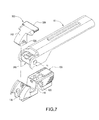
- FIG. 7 is a second schematic view of an operation status of a wiper connection seat of a preferred embodiment of the present invention.
- the wiper connection seat is used for connecting a wiper arm of a vehicle and a wiper and comprises a main body 100, a sleeve 200 and a pressing member 300.
- the main body 100 has a containing groove 110, a snap groove 120, two first pivoting portions 130 disposed opposite to each other, and a flange 140.
- the containing groove 110 has at least one snap opening 111 formed on an inner wall of the containing groove 110.
- the containing groove 110 has two snap openings 111 formed on an inner wall of the containing groove 110 of this preferred embodiment, and the snap grooves 20 are configured for snapping the wiper therein.
- the snap groove 120 and the containing groove 110 are preferably arranged opposite to each other, but the present invention is not limited to such a specific arrangement only.
- the flange 140 is preferably disposed between the two first pivoting portions 130, but the present invention is not limited to such a specific arrangement only.
- the sleeve 200 is installed in the containing groove 110, and the sleeve 200 is a socket with a substantially C-shaped cross-section, and the sleeve 200 has a pivoting groove 210 formed thereon, which is configured for pivotally coupling the wiper arm.
- the sleeve 200 includes a stop block 211 disposed thereon for stopping the wiper arm from falling out from the pivoting groove 210.
- the stop block 211 is protruded from an inner wall of the pivoting groove 210, but the present invention is not limited to such a specific arrangement only.
- At least one tenon 220 is protruded from an external side of the sleeve 200.
- the pressing member 300 is pivotally coupled to the main body 100 and covered onto the pivoting groove 210, and the pressing member 300 includes a rotating shaft 310 and a cover plate 320 extended from the rotating shaft 310, wherein the rotating shaft 310 is pivotally coupled to the main body 100. and the rotating shaft 310 has two second pivoting portions 330 disposed opposite to each other and a cleat 340, and each second pivoting portion 330 is disposed corresponding to a first pivoting portion 130, and each first pivoting portion 130 is pivotally coupled to the corresponding second pivoting portion 330, such that the pressing member 300 can be rotably coupled to the main body 100.
- first and second pivoting portions 130, 330 of the present invention are not limited to the aforementioned specific forms only, but the first pivoting portion 130 can be a protruding column and the corresponding pivotally coupled second pivoting portion 330 can be a slot; or the first pivoting portion 130 can be a slot, and the corresponding pivotally coupled second pivoting portion 330 can be a protruding column.
- the cleat 340 is disposed at a position corresponding to the flange 140 and can be moved flexibly and installed between the two second pivoting portions 330, but the present invention is not limited to such arrangement only.
- the flange 140 is snapped into the cleat 340 to fix the pressing member 300 with a rotation angle with respect to the main body 100, so as to cover the cover plate 320 onto the pivoting groove 210.
- the cover plate 320 can be opened by the rotating shaft 310.
- the wiper connection seat of the present invention is pivotally coupled to the wiper arm 10 by the sleeve 200, wherein the sleeve 200 is preferably pivotally coupled to the wiper arm axle 11 of the wiper arm 10, and the sleeve 200 further has a pivoting groove 210 with a different internal diameter to fit a wiper arm axle 11 of the different diameter.
- the wiper arm axle 11 has two guide slots 12, such that when the wiper arm axle 11 is aligned at a specific angle with respect to the sleeve 200, the stop block 211 in the pivoting groove 210 can be passed through the guide slot 12 to facilitate the installation of the wiper arm axle 11 into the pivoting groove 210.
- the wiper arm axle 11 After the wiper arm axle 11 is installed into the pivoting groove 210 and rotated to the aforementioned specific angle, the wiper arm axle 11 is fixed into the pivoting groove 210 by the stop block 211.
- the cover plate 320 of the pressing member 300 is covered onto the containing groove 110 to prevent the wiper arm axle 11 from falling out from the pivoting groove 210.
- the snap groove 120 is provided for snapping a wiper axle 21 of the wiper 20, wherein the wiper connection seat of the present invention is provided for coupling the wiper arm 10 and the wiper 20.
- the containing groove 110 can be in a shape corresponding to another shape of the wiper arm axle 11 in order to connect a non-pivotally connected wiper arm axle 11 (such as the built-in wiper arm axle 11 of the sleeve 200 as shown in FIG. 7 ), so that when the sleeve 200 is removed from the containing groove 110, the containing groove 110 can be used for connecting a wiper arm axle 11 of a particular specification.
- a non-pivotally connected wiper arm axle 11 such as the built-in wiper arm axle 11 of the sleeve 200 as shown in FIG. 7
- the wiper connection seat of the present invention is pivotally coupled to the wiper arm 10 by the sleeve 200, therefore the wiper connection seat can fit wiper arms 10 of various different specifications by simply changing the sleeve 200 with a different internal diameter.
- the present invention provides a wider scope of applicability, and the invention can fit different wiper arms by simply changing the sleeve 200 without the need of designing the connection seat with another specification.
- the position of the pivoting groove 210 remains unchanged, so that when a wiper arm 10 of a different specification is changed, the relative positions of the wiper arm 10 and the wiper 20 will not affect the overall operation.
Abstract
Description
- The present invention relates to a wiper connection seat, in particular to the wiper connection seat applicable for wiper arms for vehicles of different specifications.
- In a conventional wiper structure for vehicles, a connection seat is used for coupling a wiper arm and a wiper, and the conventional connection seat generally comes with two clasp slots, one for clasping a pivot shaft of the wiper and the other for clasping an insert pin of the wiper arm to mount the wiper onto the wiper arm. Therefore, the conventional wiper connection seat can only be connected to the wiper and wiper arm of a particular specification and the scope of the applicability is very narrow. If it is necessary to replace a wiper or a wiper arm, the connection seat of the particular specification must be changed at the same time, thus resulting in an inconvenient maintenance and a high manufacturing cost.
- Therefore, it is a primary objective of the present invention to provide a wiper connection seat applicable for wiper arms of different specifications.
- To achieve the aforementioned objective, the present invention provides a wiper connection seat for coupling a wiper arm, comprising: a main body, a sleeve and a pressing member. The main body has a containing groove; the sleeve is installed in the containing groove and has a pivoting groove for pivotally coupling the wiper arm; and the pressing member is pivotally coupled to the main body and covered onto the pivoting groove.
- In the wiper connection seat of the present invention, the main body preferably includes a first pivoting portion, and the pressing member includes a second pivoting portion, wherein the first pivoting portion is pivotally coupled to the second pivoting portion.
- In the wiper connection seat of the present invention, the main body is preferably a protruding column, and the second pivoting portion is preferably a slot.
- In the wiper connection seat of the present invention, the first pivoting portion is preferably a slot, and the second pivoting portion is preferably a protruding column.
- In the wiper connection seat of the present invention, the pressing member preferably includes a cleat, and a flange convexly formed at a position of the main body and corresponding to the cleat and coupled with the cleat.
- In the wiper connection seat of the present invention, the pressing member preferably includes a cover plate provided for covering the containing groove.
- In the wiper connection seat of the present invention, the wiper connection seat is preferably coupled to a wiper and the wiper arm, and the main body preferably has a snap groove for snapping the wiper.
- In the wiper connection seat of the present invention, the sleeve includes a stop block for stopping the wiper arm from falling out from the pivoting groove and abutting the wiper arms.
- In the wiper connection seat of the present invention, the stop block is protruded from an inner wall of the pivoting groove.
- In the wiper connection seat of the present invention, a tenon is protruded from an external side of the sleeve, and a snap opening is formed on an inner wall of the containing groove, and the tenon is snapped into the snap opening to fix the sleeve into the containing groove.
- In the wiper connection seat of the present invention, the separately installed sleeve is pivotally coupled to the wiper arm axle, so that the wiper connection seat can fit wiper arms of different specifications by simply changing the sleeve, and the drawbacks of the prior art can be overcome effectively.
-
FIG. 1 is a first exploded view of a wiper connection seat of a preferred embodiment of the present invention; -
FIG. 2 is a second exploded view of a wiper connection seat of a preferred embodiment of the present invention; -
FIG. 3 is a perspective view of a wiper connection seat of a preferred embodiment of the present invention; -
FIG. 4 is a cross-sectional view of a wiper connection seat of a preferred embodiment of the present invention; -
FIG. 5 is a first schematic view of an operation status of a wiper connection seat of a preferred embodiment of the present invention; -
FIG. 6 is a cross-sectional view of an operation status of a wiper connection seat of a preferred embodiment of the present invention; and -
FIG. 7 is a second schematic view of an operation status of a wiper connection seat of a preferred embodiment of the present invention. - The technical contents of the present invention will become apparent with the detailed description of preferred embodiments accompanied with the illustration of related drawings as follows.
- With reference to
FIGS. 1 and2 for a wiper connection seat in accordance with a preferred embodiment of the present invention, the wiper connection seat is used for connecting a wiper arm of a vehicle and a wiper and comprises amain body 100, asleeve 200 and apressing member 300. - The
main body 100 has a containinggroove 110, asnap groove 120, two first pivotingportions 130 disposed opposite to each other, and aflange 140. The containinggroove 110 has at least one snap opening 111 formed on an inner wall of the containinggroove 110. Preferably, the containinggroove 110 has twosnap openings 111 formed on an inner wall of the containinggroove 110 of this preferred embodiment, and thesnap grooves 20 are configured for snapping the wiper therein. In this preferred embodiment, thesnap groove 120 and the containinggroove 110 are preferably arranged opposite to each other, but the present invention is not limited to such a specific arrangement only. Theflange 140 is preferably disposed between the twofirst pivoting portions 130, but the present invention is not limited to such a specific arrangement only. - As shown in
FIGS. 3 and 4 , thesleeve 200 is installed in the containinggroove 110, and thesleeve 200 is a socket with a substantially C-shaped cross-section, and thesleeve 200 has apivoting groove 210 formed thereon, which is configured for pivotally coupling the wiper arm. Thesleeve 200 includes astop block 211 disposed thereon for stopping the wiper arm from falling out from thepivoting groove 210. Thestop block 211 is protruded from an inner wall of thepivoting groove 210, but the present invention is not limited to such a specific arrangement only. At least onetenon 220 is protruded from an external side of thesleeve 200. In this preferred embodiment, there are twotenons 220 protruded from the external side of thesleeve 200, and each being installed at a position corresponding to asnap opening 111 and snapped into thecorresponding snap opening 111 to fix thesleeve 200 into the containinggroove 110. - The pressing
member 300 is pivotally coupled to themain body 100 and covered onto thepivoting groove 210, and thepressing member 300 includes a rotatingshaft 310 and acover plate 320 extended from the rotatingshaft 310, wherein the rotatingshaft 310 is pivotally coupled to themain body 100. and the rotatingshaft 310 has two second pivotingportions 330 disposed opposite to each other and acleat 340, and eachsecond pivoting portion 330 is disposed corresponding to afirst pivoting portion 130, and eachfirst pivoting portion 130 is pivotally coupled to the correspondingsecond pivoting portion 330, such that thepressing member 300 can be rotably coupled to themain body 100. However, the corresponding first andsecond pivoting portions first pivoting portion 130 can be a protruding column and the corresponding pivotally coupledsecond pivoting portion 330 can be a slot; or thefirst pivoting portion 130 can be a slot, and the corresponding pivotally coupledsecond pivoting portion 330 can be a protruding column. Thecleat 340 is disposed at a position corresponding to theflange 140 and can be moved flexibly and installed between the twosecond pivoting portions 330, but the present invention is not limited to such arrangement only. Theflange 140 is snapped into thecleat 340 to fix the pressingmember 300 with a rotation angle with respect to themain body 100, so as to cover thecover plate 320 onto thepivoting groove 210. In addition, thecover plate 320 can be opened by the rotatingshaft 310. - As shown in
FIGS. 5 and6 , the wiper connection seat of the present invention is pivotally coupled to thewiper arm 10 by thesleeve 200, wherein thesleeve 200 is preferably pivotally coupled to thewiper arm axle 11 of thewiper arm 10, and thesleeve 200 further has apivoting groove 210 with a different internal diameter to fit awiper arm axle 11 of the different diameter. Thewiper arm axle 11 has twoguide slots 12, such that when thewiper arm axle 11 is aligned at a specific angle with respect to thesleeve 200, thestop block 211 in thepivoting groove 210 can be passed through theguide slot 12 to facilitate the installation of thewiper arm axle 11 into thepivoting groove 210. After thewiper arm axle 11 is installed into thepivoting groove 210 and rotated to the aforementioned specific angle, thewiper arm axle 11 is fixed into thepivoting groove 210 by thestop block 211. In addition, thecover plate 320 of thepressing member 300 is covered onto the containinggroove 110 to prevent thewiper arm axle 11 from falling out from thepivoting groove 210. Thesnap groove 120 is provided for snapping awiper axle 21 of thewiper 20, wherein the wiper connection seat of the present invention is provided for coupling thewiper arm 10 and thewiper 20. - As shown in
FIG. 7 , the containinggroove 110 can be in a shape corresponding to another shape of thewiper arm axle 11 in order to connect a non-pivotally connected wiper arm axle 11 (such as the built-inwiper arm axle 11 of thesleeve 200 as shown inFIG. 7 ), so that when thesleeve 200 is removed from the containinggroove 110, the containinggroove 110 can be used for connecting awiper arm axle 11 of a particular specification. - Since the wiper connection seat of the present invention is pivotally coupled to the
wiper arm 10 by thesleeve 200, therefore the wiper connection seat can fitwiper arms 10 of various different specifications by simply changing thesleeve 200 with a different internal diameter. Compared with the prior art, the present invention provides a wider scope of applicability, and the invention can fit different wiper arms by simply changing thesleeve 200 without the need of designing the connection seat with another specification. With the design of replacing thesleeve 200, the position of thepivoting groove 210 remains unchanged, so that when awiper arm 10 of a different specification is changed, the relative positions of thewiper arm 10 and thewiper 20 will not affect the overall operation.
Claims (10)
- A wiper connection seat, applied for connecting a wiper arm (10), comprising:a main body (100), having a containing groove (110);a sleeve (200), installed in the containing groove (110), and having a pivoting groove (210) for pivotally coupling the wiper arm (10); anda pressing member (300), pivotally coupled to the main body (100) and covered onto the pivoting groove (210).
- The wiper connection seat of claim 1, wherein the main body (100) comprises a first pivoting portion (130) and the pressing member (300) comprises a second pivoting portion (330), and the first pivoting portion (130) is pivotally coupled to the second pivoting portion (330).
- The wiper connection seat of claim 2, wherein the first pivoting portion (130) is a protruding column and the second pivoting portion (330) is a slot.
- The wiper connection seat of claim 2, wherein the first pivoting portion (130) is a slot and the second pivoting portion (330) is a protruding column.
- The wiper connection seat of any of the preceding claims, wherein the pressing member (300) comprises a cleat (340), and the main body (100) has a flange (140) protruded from a position corresponding to the cleat (340) and coupled to the cleat (340).
- The wiper connection seat of any of the preceding claims, wherein the pressing member (300) comprises a cover plate (320) covered onto the pivoting groove (210).
- The wiper connection seat of any of the preceding claims, wherein the wiper connection seat is configured for coupling a wiper (20) and the wiper arm (10), and the main body (100) has a snap groove (120) for snapping the wiper (20) therein.
- The wiper connection seat of any of the preceding claims, wherein the sleeve (200) has a stop block (211) disposed thereon and provided for stopping the wiper arm (10) from falling out from the pivoting groove (210) and abutting the wiper arm (10).
- The wiper connection seat of claim 8, wherein the stop block (211) is protruded from an inner wall of the pivoting groove (210).
- The wiper connection seat of any of the preceding claims, wherein the sleeve (200) has a tenon (220) protruded from an external side of the sleeve (200), and the containing groove (110) has a snap opening (111) formed on an inner wall of the containing groove (110), and the tenon (220) is snapped into the snap opening (111) to fix the sleeve (200) into the containing groove (110).
Priority Applications (1)
| Application Number | Priority Date | Filing Date | Title |
|---|---|---|---|
| EP13154076.7A EP2762369B1 (en) | 2013-02-05 | 2013-02-05 | Wiper connection seat |
Applications Claiming Priority (1)
| Application Number | Priority Date | Filing Date | Title |
|---|---|---|---|
| EP13154076.7A EP2762369B1 (en) | 2013-02-05 | 2013-02-05 | Wiper connection seat |
Publications (2)
| Publication Number | Publication Date |
|---|---|
| EP2762369A1 true EP2762369A1 (en) | 2014-08-06 |
| EP2762369B1 EP2762369B1 (en) | 2016-11-23 |
Family
ID=47709951
Family Applications (1)
| Application Number | Title | Priority Date | Filing Date |
|---|---|---|---|
| EP13154076.7A Not-in-force EP2762369B1 (en) | 2013-02-05 | 2013-02-05 | Wiper connection seat |
Country Status (1)
| Country | Link |
|---|---|
| EP (1) | EP2762369B1 (en) |
Cited By (2)
| Publication number | Priority date | Publication date | Assignee | Title |
|---|---|---|---|---|
| JP2016117471A (en) * | 2014-12-22 | 2016-06-30 | ケーシーダブリュー コーポレーション | Connector connecting wiper blade with wiper arm |
| US11608033B2 (en) * | 2016-05-19 | 2023-03-21 | Pylon Manufacturing Corporation | Windshield wiper connector |
Citations (5)
| Publication number | Priority date | Publication date | Assignee | Title |
|---|---|---|---|---|
| US6625842B1 (en) * | 1999-10-28 | 2003-09-30 | Robert Bosch Gmbh | Wiper device for motor vehicle panes |
| FR2838693A1 (en) * | 2002-04-22 | 2003-10-24 | Valeo Systemes Dessuyage | System for attaching windscreen wiper blade mounting to arm comprises pivot attached to arm which fits into bearing with ribs on its underside, over which clips on mounting fit |
| US20100050361A1 (en) * | 2008-08-26 | 2010-03-04 | Chuan-Chih Chang | Windshield wiper connector |
| DE102010030880A1 (en) * | 2010-07-02 | 2012-01-05 | Robert Bosch Gmbh | Connecting device for the articulated connection of a wiper arm with a wiper blade |
| US20130007976A1 (en) * | 2011-07-06 | 2013-01-10 | Chih-Ming Yang | Windshield wiper combining assembly of combining driven wiper arm |
-
2013
- 2013-02-05 EP EP13154076.7A patent/EP2762369B1/en not_active Not-in-force
Patent Citations (5)
| Publication number | Priority date | Publication date | Assignee | Title |
|---|---|---|---|---|
| US6625842B1 (en) * | 1999-10-28 | 2003-09-30 | Robert Bosch Gmbh | Wiper device for motor vehicle panes |
| FR2838693A1 (en) * | 2002-04-22 | 2003-10-24 | Valeo Systemes Dessuyage | System for attaching windscreen wiper blade mounting to arm comprises pivot attached to arm which fits into bearing with ribs on its underside, over which clips on mounting fit |
| US20100050361A1 (en) * | 2008-08-26 | 2010-03-04 | Chuan-Chih Chang | Windshield wiper connector |
| DE102010030880A1 (en) * | 2010-07-02 | 2012-01-05 | Robert Bosch Gmbh | Connecting device for the articulated connection of a wiper arm with a wiper blade |
| US20130007976A1 (en) * | 2011-07-06 | 2013-01-10 | Chih-Ming Yang | Windshield wiper combining assembly of combining driven wiper arm |
Cited By (2)
| Publication number | Priority date | Publication date | Assignee | Title |
|---|---|---|---|---|
| JP2016117471A (en) * | 2014-12-22 | 2016-06-30 | ケーシーダブリュー コーポレーション | Connector connecting wiper blade with wiper arm |
| US11608033B2 (en) * | 2016-05-19 | 2023-03-21 | Pylon Manufacturing Corporation | Windshield wiper connector |
Also Published As
| Publication number | Publication date |
|---|---|
| EP2762369B1 (en) | 2016-11-23 |
Similar Documents
| Publication | Publication Date | Title |
|---|---|---|
| TWI392605B (en) | Device for attaching a windscreen-wiper blade to an arm | |
| US20130025084A1 (en) | Wiper blade connector | |
| US20130185890A1 (en) | Wiper connector and bolt-stabilizing sleeve adaptor | |
| US6868582B2 (en) | Computer hinge | |
| US9803767B2 (en) | Fluid device unit | |
| WO2012056646A1 (en) | Clip and connection structutr | |
| EP3433132A1 (en) | Flexible plastic snap-receiving socket | |
| CN101351651A (en) | Mounting structure | |
| EP2762369A1 (en) | Wiper connection seat | |
| WO2011058615A1 (en) | Hinge device | |
| US20180072094A1 (en) | Wheel cover of aluminum alloy wheel | |
| TW201510700A (en) | Door device and storage equipment | |
| EP3450666A1 (en) | Slide hinge and cabinet | |
| US10288099B2 (en) | Attachment feature for securing two parallel workpieces together | |
| CN112997368B (en) | Vehicle connector | |
| JP5918027B2 (en) | Tire valve unit | |
| JP5474650B2 (en) | Cover for hinge | |
| US8403282B2 (en) | Clamp device | |
| US9316028B2 (en) | Vehicle door latch | |
| US9708838B2 (en) | Vehicle door handle device | |
| JP7365703B2 (en) | Wiper arm cover mounting structure | |
| CN203836382U (en) | Pipe clamp for vehicle | |
| EP2937500A1 (en) | Pivot for a door | |
| JP2019043418A (en) | Structure of lid member | |
| KR101657689B1 (en) | Holding module for measuring car headlamp and assembling method of the same |
Legal Events
| Date | Code | Title | Description |
|---|---|---|---|
| PUAI | Public reference made under article 153(3) epc to a published international application that has entered the european phase |
Free format text: ORIGINAL CODE: 0009012 |
|
| 17P | Request for examination filed |
Effective date: 20131002 |
|
| AK | Designated contracting states |
Kind code of ref document: A1 Designated state(s): AL AT BE BG CH CY CZ DE DK EE ES FI FR GB GR HR HU IE IS IT LI LT LU LV MC MK MT NL NO PL PT RO RS SE SI SK SM TR |
|
| AX | Request for extension of the european patent |
Extension state: BA ME |
|
| 17Q | First examination report despatched |
Effective date: 20151023 |
|
| GRAP | Despatch of communication of intention to grant a patent |
Free format text: ORIGINAL CODE: EPIDOSNIGR1 |
|
| INTG | Intention to grant announced |
Effective date: 20160608 |
|
| GRAS | Grant fee paid |
Free format text: ORIGINAL CODE: EPIDOSNIGR3 |
|
| GRAA | (expected) grant |
Free format text: ORIGINAL CODE: 0009210 |
|
| AK | Designated contracting states |
Kind code of ref document: B1 Designated state(s): AL AT BE BG CH CY CZ DE DK EE ES FI FR GB GR HR HU IE IS IT LI LT LU LV MC MK MT NL NO PL PT RO RS SE SI SK SM TR |
|
| REG | Reference to a national code |
Ref country code: GB Ref legal event code: FG4D |
|
| REG | Reference to a national code |
Ref country code: CH Ref legal event code: EP |
|
| REG | Reference to a national code |
Ref country code: IE Ref legal event code: FG4D |
|
| REG | Reference to a national code |
Ref country code: AT Ref legal event code: REF Ref document number: 847555 Country of ref document: AT Kind code of ref document: T Effective date: 20161215 |
|
| REG | Reference to a national code |
Ref country code: DE Ref legal event code: R096 Ref document number: 602013014294 Country of ref document: DE |
|
| REG | Reference to a national code |
Ref country code: FR Ref legal event code: PLFP Year of fee payment: 5 |
|
| PG25 | Lapsed in a contracting state [announced via postgrant information from national office to epo] |
Ref country code: LV Free format text: LAPSE BECAUSE OF FAILURE TO SUBMIT A TRANSLATION OF THE DESCRIPTION OR TO PAY THE FEE WITHIN THE PRESCRIBED TIME-LIMIT Effective date: 20161123 |
|
| REG | Reference to a national code |
Ref country code: LT Ref legal event code: MG4D |
|
| REG | Reference to a national code |
Ref country code: NL Ref legal event code: MP Effective date: 20161123 |
|
| REG | Reference to a national code |
Ref country code: AT Ref legal event code: MK05 Ref document number: 847555 Country of ref document: AT Kind code of ref document: T Effective date: 20161123 |
|
| PG25 | Lapsed in a contracting state [announced via postgrant information from national office to epo] |
Ref country code: SE Free format text: LAPSE BECAUSE OF FAILURE TO SUBMIT A TRANSLATION OF THE DESCRIPTION OR TO PAY THE FEE WITHIN THE PRESCRIBED TIME-LIMIT Effective date: 20161123 Ref country code: LT Free format text: LAPSE BECAUSE OF FAILURE TO SUBMIT A TRANSLATION OF THE DESCRIPTION OR TO PAY THE FEE WITHIN THE PRESCRIBED TIME-LIMIT Effective date: 20161123 Ref country code: NO Free format text: LAPSE BECAUSE OF FAILURE TO SUBMIT A TRANSLATION OF THE DESCRIPTION OR TO PAY THE FEE WITHIN THE PRESCRIBED TIME-LIMIT Effective date: 20170223 Ref country code: NL Free format text: LAPSE BECAUSE OF FAILURE TO SUBMIT A TRANSLATION OF THE DESCRIPTION OR TO PAY THE FEE WITHIN THE PRESCRIBED TIME-LIMIT Effective date: 20161123 Ref country code: GR Free format text: LAPSE BECAUSE OF FAILURE TO SUBMIT A TRANSLATION OF THE DESCRIPTION OR TO PAY THE FEE WITHIN THE PRESCRIBED TIME-LIMIT Effective date: 20170224 |
|
| PGFP | Annual fee paid to national office [announced via postgrant information from national office to epo] |
Ref country code: FR Payment date: 20170203 Year of fee payment: 5 Ref country code: DE Payment date: 20170224 Year of fee payment: 5 |
|
| PG25 | Lapsed in a contracting state [announced via postgrant information from national office to epo] |
Ref country code: AT Free format text: LAPSE BECAUSE OF FAILURE TO SUBMIT A TRANSLATION OF THE DESCRIPTION OR TO PAY THE FEE WITHIN THE PRESCRIBED TIME-LIMIT Effective date: 20161123 Ref country code: ES Free format text: LAPSE BECAUSE OF FAILURE TO SUBMIT A TRANSLATION OF THE DESCRIPTION OR TO PAY THE FEE WITHIN THE PRESCRIBED TIME-LIMIT Effective date: 20161123 Ref country code: RS Free format text: LAPSE BECAUSE OF FAILURE TO SUBMIT A TRANSLATION OF THE DESCRIPTION OR TO PAY THE FEE WITHIN THE PRESCRIBED TIME-LIMIT Effective date: 20161123 Ref country code: HR Free format text: LAPSE BECAUSE OF FAILURE TO SUBMIT A TRANSLATION OF THE DESCRIPTION OR TO PAY THE FEE WITHIN THE PRESCRIBED TIME-LIMIT Effective date: 20161123 Ref country code: BE Free format text: LAPSE BECAUSE OF NON-PAYMENT OF DUE FEES Effective date: 20170228 Ref country code: PT Free format text: LAPSE BECAUSE OF FAILURE TO SUBMIT A TRANSLATION OF THE DESCRIPTION OR TO PAY THE FEE WITHIN THE PRESCRIBED TIME-LIMIT Effective date: 20170323 Ref country code: PL Free format text: LAPSE BECAUSE OF FAILURE TO SUBMIT A TRANSLATION OF THE DESCRIPTION OR TO PAY THE FEE WITHIN THE PRESCRIBED TIME-LIMIT Effective date: 20161123 Ref country code: FI Free format text: LAPSE BECAUSE OF FAILURE TO SUBMIT A TRANSLATION OF THE DESCRIPTION OR TO PAY THE FEE WITHIN THE PRESCRIBED TIME-LIMIT Effective date: 20161123 |
|
| PGFP | Annual fee paid to national office [announced via postgrant information from national office to epo] |
Ref country code: GB Payment date: 20170202 Year of fee payment: 5 |
|
| PGFP | Annual fee paid to national office [announced via postgrant information from national office to epo] |
Ref country code: IT Payment date: 20170130 Year of fee payment: 5 |
|
| PG25 | Lapsed in a contracting state [announced via postgrant information from national office to epo] |
Ref country code: CZ Free format text: LAPSE BECAUSE OF FAILURE TO SUBMIT A TRANSLATION OF THE DESCRIPTION OR TO PAY THE FEE WITHIN THE PRESCRIBED TIME-LIMIT Effective date: 20161123 Ref country code: SK Free format text: LAPSE BECAUSE OF FAILURE TO SUBMIT A TRANSLATION OF THE DESCRIPTION OR TO PAY THE FEE WITHIN THE PRESCRIBED TIME-LIMIT Effective date: 20161123 Ref country code: EE Free format text: LAPSE BECAUSE OF FAILURE TO SUBMIT A TRANSLATION OF THE DESCRIPTION OR TO PAY THE FEE WITHIN THE PRESCRIBED TIME-LIMIT Effective date: 20161123 Ref country code: DK Free format text: LAPSE BECAUSE OF FAILURE TO SUBMIT A TRANSLATION OF THE DESCRIPTION OR TO PAY THE FEE WITHIN THE PRESCRIBED TIME-LIMIT Effective date: 20161123 Ref country code: RO Free format text: LAPSE BECAUSE OF FAILURE TO SUBMIT A TRANSLATION OF THE DESCRIPTION OR TO PAY THE FEE WITHIN THE PRESCRIBED TIME-LIMIT Effective date: 20161123 |
|
| REG | Reference to a national code |
Ref country code: DE Ref legal event code: R097 Ref document number: 602013014294 Country of ref document: DE |
|
| PG25 | Lapsed in a contracting state [announced via postgrant information from national office to epo] |
Ref country code: BG Free format text: LAPSE BECAUSE OF FAILURE TO SUBMIT A TRANSLATION OF THE DESCRIPTION OR TO PAY THE FEE WITHIN THE PRESCRIBED TIME-LIMIT Effective date: 20170223 Ref country code: SM Free format text: LAPSE BECAUSE OF FAILURE TO SUBMIT A TRANSLATION OF THE DESCRIPTION OR TO PAY THE FEE WITHIN THE PRESCRIBED TIME-LIMIT Effective date: 20161123 Ref country code: BE Free format text: LAPSE BECAUSE OF FAILURE TO SUBMIT A TRANSLATION OF THE DESCRIPTION OR TO PAY THE FEE WITHIN THE PRESCRIBED TIME-LIMIT Effective date: 20161123 |
|
| PG25 | Lapsed in a contracting state [announced via postgrant information from national office to epo] |
Ref country code: MC Free format text: LAPSE BECAUSE OF FAILURE TO SUBMIT A TRANSLATION OF THE DESCRIPTION OR TO PAY THE FEE WITHIN THE PRESCRIBED TIME-LIMIT Effective date: 20161123 |
|
| PLBE | No opposition filed within time limit |
Free format text: ORIGINAL CODE: 0009261 |
|
| REG | Reference to a national code |
Ref country code: CH Ref legal event code: PL |
|
| STAA | Information on the status of an ep patent application or granted ep patent |
Free format text: STATUS: NO OPPOSITION FILED WITHIN TIME LIMIT |
|
| PG25 | Lapsed in a contracting state [announced via postgrant information from national office to epo] |
Ref country code: CH Free format text: LAPSE BECAUSE OF NON-PAYMENT OF DUE FEES Effective date: 20170228 Ref country code: LI Free format text: LAPSE BECAUSE OF NON-PAYMENT OF DUE FEES Effective date: 20170228 |
|
| 26N | No opposition filed |
Effective date: 20170824 |
|
| REG | Reference to a national code |
Ref country code: IE Ref legal event code: MM4A |
|
| PG25 | Lapsed in a contracting state [announced via postgrant information from national office to epo] |
Ref country code: SI Free format text: LAPSE BECAUSE OF FAILURE TO SUBMIT A TRANSLATION OF THE DESCRIPTION OR TO PAY THE FEE WITHIN THE PRESCRIBED TIME-LIMIT Effective date: 20161123 |
|
| PG25 | Lapsed in a contracting state [announced via postgrant information from national office to epo] |
Ref country code: LU Free format text: LAPSE BECAUSE OF NON-PAYMENT OF DUE FEES Effective date: 20170205 |
|
| PG25 | Lapsed in a contracting state [announced via postgrant information from national office to epo] |
Ref country code: IE Free format text: LAPSE BECAUSE OF NON-PAYMENT OF DUE FEES Effective date: 20170205 |
|
| REG | Reference to a national code |
Ref country code: DE Ref legal event code: R119 Ref document number: 602013014294 Country of ref document: DE |
|
| PG25 | Lapsed in a contracting state [announced via postgrant information from national office to epo] |
Ref country code: MT Free format text: LAPSE BECAUSE OF NON-PAYMENT OF DUE FEES Effective date: 20170205 |
|
| GBPC | Gb: european patent ceased through non-payment of renewal fee |
Effective date: 20180205 |
|
| REG | Reference to a national code |
Ref country code: FR Ref legal event code: ST Effective date: 20181031 |
|
| PG25 | Lapsed in a contracting state [announced via postgrant information from national office to epo] |
Ref country code: DE Free format text: LAPSE BECAUSE OF NON-PAYMENT OF DUE FEES Effective date: 20180901 |
|
| PG25 | Lapsed in a contracting state [announced via postgrant information from national office to epo] |
Ref country code: FR Free format text: LAPSE BECAUSE OF NON-PAYMENT OF DUE FEES Effective date: 20180228 Ref country code: GB Free format text: LAPSE BECAUSE OF NON-PAYMENT OF DUE FEES Effective date: 20180205 Ref country code: IT Free format text: LAPSE BECAUSE OF NON-PAYMENT OF DUE FEES Effective date: 20180205 |
|
| PG25 | Lapsed in a contracting state [announced via postgrant information from national office to epo] |
Ref country code: HU Free format text: LAPSE BECAUSE OF FAILURE TO SUBMIT A TRANSLATION OF THE DESCRIPTION OR TO PAY THE FEE WITHIN THE PRESCRIBED TIME-LIMIT; INVALID AB INITIO Effective date: 20130205 |
|
| PG25 | Lapsed in a contracting state [announced via postgrant information from national office to epo] |
Ref country code: CY Free format text: LAPSE BECAUSE OF NON-PAYMENT OF DUE FEES Effective date: 20161123 |
|
| PG25 | Lapsed in a contracting state [announced via postgrant information from national office to epo] |
Ref country code: MK Free format text: LAPSE BECAUSE OF FAILURE TO SUBMIT A TRANSLATION OF THE DESCRIPTION OR TO PAY THE FEE WITHIN THE PRESCRIBED TIME-LIMIT Effective date: 20161123 |
|
| PG25 | Lapsed in a contracting state [announced via postgrant information from national office to epo] |
Ref country code: TR Free format text: LAPSE BECAUSE OF FAILURE TO SUBMIT A TRANSLATION OF THE DESCRIPTION OR TO PAY THE FEE WITHIN THE PRESCRIBED TIME-LIMIT Effective date: 20161123 |
|
| PG25 | Lapsed in a contracting state [announced via postgrant information from national office to epo] |
Ref country code: AL Free format text: LAPSE BECAUSE OF FAILURE TO SUBMIT A TRANSLATION OF THE DESCRIPTION OR TO PAY THE FEE WITHIN THE PRESCRIBED TIME-LIMIT Effective date: 20161123 Ref country code: IS Free format text: LAPSE BECAUSE OF FAILURE TO SUBMIT A TRANSLATION OF THE DESCRIPTION OR TO PAY THE FEE WITHIN THE PRESCRIBED TIME-LIMIT Effective date: 20170323 |