EP2762319A1 - Printer apparatus and printer apparatus control method - Google Patents
Printer apparatus and printer apparatus control method Download PDFInfo
- Publication number
- EP2762319A1 EP2762319A1 EP14152835.6A EP14152835A EP2762319A1 EP 2762319 A1 EP2762319 A1 EP 2762319A1 EP 14152835 A EP14152835 A EP 14152835A EP 2762319 A1 EP2762319 A1 EP 2762319A1
- Authority
- EP
- European Patent Office
- Prior art keywords
- roller
- recording paper
- recording sheet
- printing
- printer apparatus
- Prior art date
- Legal status (The legal status is an assumption and is not a legal conclusion. Google has not performed a legal analysis and makes no representation as to the accuracy of the status listed.)
- Granted
Links
Images







Classifications
-
- B—PERFORMING OPERATIONS; TRANSPORTING
- B41—PRINTING; LINING MACHINES; TYPEWRITERS; STAMPS
- B41J—TYPEWRITERS; SELECTIVE PRINTING MECHANISMS, i.e. MECHANISMS PRINTING OTHERWISE THAN FROM A FORME; CORRECTION OF TYPOGRAPHICAL ERRORS
- B41J15/00—Devices or arrangements of selective printing mechanisms, e.g. ink-jet printers or thermal printers, specially adapted for supporting or handling copy material in continuous form, e.g. webs
- B41J15/16—Means for tensioning or winding the web
-
- B—PERFORMING OPERATIONS; TRANSPORTING
- B41—PRINTING; LINING MACHINES; TYPEWRITERS; STAMPS
- B41J—TYPEWRITERS; SELECTIVE PRINTING MECHANISMS, i.e. MECHANISMS PRINTING OTHERWISE THAN FROM A FORME; CORRECTION OF TYPOGRAPHICAL ERRORS
- B41J11/00—Devices or arrangements of selective printing mechanisms, e.g. ink-jet printers or thermal printers, for supporting or handling copy material in sheet or web form
- B41J11/48—Apparatus for condensed record, tally strip, or like work using two or more papers, or sets of papers, e.g. devices for switching over from handling of copy material in sheet form to handling of copy material in continuous form and vice versa or point-of-sale printers comprising means for printing on continuous copy material, e.g. journal for tills, and on single sheets, e.g. cheques or receipts
- B41J11/485—Means for selecting a type of copy material amongst different types of copy material in the printing apparatus
-
- B—PERFORMING OPERATIONS; TRANSPORTING
- B41—PRINTING; LINING MACHINES; TYPEWRITERS; STAMPS
- B41J—TYPEWRITERS; SELECTIVE PRINTING MECHANISMS, i.e. MECHANISMS PRINTING OTHERWISE THAN FROM A FORME; CORRECTION OF TYPOGRAPHICAL ERRORS
- B41J15/00—Devices or arrangements of selective printing mechanisms, e.g. ink-jet printers or thermal printers, specially adapted for supporting or handling copy material in continuous form, e.g. webs
- B41J15/18—Multiple web-feeding apparatus
-
- B—PERFORMING OPERATIONS; TRANSPORTING
- B65—CONVEYING; PACKING; STORING; HANDLING THIN OR FILAMENTARY MATERIAL
- B65H—HANDLING THIN OR FILAMENTARY MATERIAL, e.g. SHEETS, WEBS, CABLES
- B65H20/00—Advancing webs
- B65H20/02—Advancing webs by friction roller
-
- G—PHYSICS
- G07—CHECKING-DEVICES
- G07B—TICKET-ISSUING APPARATUS; FARE-REGISTERING APPARATUS; FRANKING APPARATUS
- G07B1/00—Machines for printing and issuing tickets
-
- B—PERFORMING OPERATIONS; TRANSPORTING
- B65—CONVEYING; PACKING; STORING; HANDLING THIN OR FILAMENTARY MATERIAL
- B65H—HANDLING THIN OR FILAMENTARY MATERIAL, e.g. SHEETS, WEBS, CABLES
- B65H2301/00—Handling processes for sheets or webs
- B65H2301/40—Type of handling process
- B65H2301/41—Winding, unwinding
- B65H2301/413—Supporting web roll
- B65H2301/4139—Supporting means for several rolls
-
- B—PERFORMING OPERATIONS; TRANSPORTING
- B65—CONVEYING; PACKING; STORING; HANDLING THIN OR FILAMENTARY MATERIAL
- B65H—HANDLING THIN OR FILAMENTARY MATERIAL, e.g. SHEETS, WEBS, CABLES
- B65H2404/00—Parts for transporting or guiding the handled material
- B65H2404/10—Rollers
- B65H2404/14—Roller pairs
- B65H2404/142—Roller pairs arranged on movable frame
- B65H2404/1421—Roller pairs arranged on movable frame rotating, pivoting or oscillating around an axis, e.g. parallel to the roller axis
-
- B—PERFORMING OPERATIONS; TRANSPORTING
- B65—CONVEYING; PACKING; STORING; HANDLING THIN OR FILAMENTARY MATERIAL
- B65H—HANDLING THIN OR FILAMENTARY MATERIAL, e.g. SHEETS, WEBS, CABLES
- B65H2404/00—Parts for transporting or guiding the handled material
- B65H2404/10—Rollers
- B65H2404/14—Roller pairs
- B65H2404/143—Roller pairs driving roller and idler roller arrangement
-
- B—PERFORMING OPERATIONS; TRANSPORTING
- B65—CONVEYING; PACKING; STORING; HANDLING THIN OR FILAMENTARY MATERIAL
- B65H—HANDLING THIN OR FILAMENTARY MATERIAL, e.g. SHEETS, WEBS, CABLES
- B65H2404/00—Parts for transporting or guiding the handled material
- B65H2404/10—Rollers
- B65H2404/14—Roller pairs
- B65H2404/144—Roller pairs with relative movement of the rollers to / from each other
Definitions
- the present invention relates to a printer apparatus and a printer apparatus control method.
- Printers for issuing receipts are widely used in various applications including cash registers, Automated Teller Machines (ATM), and Cash Dispensers (CD), for example.
- Such printers are configured to issue a receipt by conveying a recording sheet such as thermal recording paper that is wound into a roll, printing objects such as characters on the recording sheet using a print head, and conveying the recording sheet up to a predetermined length so that the recording sheet may be cut at the predetermined length by a cutter (See, e.g., Japanese Laid-Open Patent Publication No. 2003-19845 , and Japanese Laid-Open Patent Publication No. 2007-130842 ).
- the printer apparatus when measures are implemented to enable a printer apparatus to print on multiple sets of recording paper, the printer apparatus may be enlarged or the structure of the printer apparatus may be complicated. In turn, the price of the printer apparatus may increase and the printer apparatus may be prone to failure and defects, for example. Accordingly, a printer apparatus that is capable of printing on different sets of recording paper while having a compact and simple structure is desired.
- a printer apparatus includes a printing part including a platen roller and a print head for printing objects onto a recording sheet, and a feeding part configured to feed the recording sheet to the printing part.
- the feeding part includes a first feed port and a second feed port for feeding the recording sheet, a first roller for conveying a first recording sheet fed through the first feed port, a second roller for conveying a second recording sheet fed through the second feed port, a delivery port for feeding the first recording sheet conveyed by the first roller and the second recording sheet conveyed by the second roller, a tension member having elasticity, a third roller rotatably connected to the tension member and being pressed toward the first roller by the elasticity of the tension member, and a fourth roller rotatably connected to the tension member and being pressed toward the second roller by the elasticity of the tension member.
- a control method for controlling a printer apparatus including a printing part that includes a print head and a platen roller driven by a printing part motor, and a feeding part for feeding a recording sheet to the printing part, the feeding part including a plurality of feed ports for feeding different recording sheets, a first roller for conveying a first recording sheet fed through a first feed port, a second roller for conveying a second recording sheet fed through a second feed port, a tension member having elasticity, a third roller rotatably connected to the tension member, and a fourth roller rotatably connected to the tension member.
- the control method includes, when switching the recording sheet subject to printing at the printing part from the first recording sheet to the second recording sheet, stopping rotation of the printing part motor while the first recording sheet is held between the print head and the platen roller, rotating the second roller and conveying the second recording sheet toward the printing part while the first recording sheet is held between the print head and the platen roller, and rotating the printing part motor and releasing the first recording sheet from the print head and the platen roller when the second recording sheet is conveyed to a predetermined position.
- a printer apparatus capable of printing on different recording sheets and having a compact and simple structure may be provided.
- the printer apparatus according to the first embodiment includes a printing part 10, a cutter part 20, and a recording paper feeding part 30 that is capable of feeding two different sets of recording paper to the printing part 10.
- recording paper is an example of a recording sheet.
- the printing part 10 includes a thermal head 11, a platen roller 12, a printing part motor 13, and a gear 14.
- the thermal head 11 is a print head for printing objects on recording paper.
- the thermal head 11 is configured to print objects on recording paper that is held between the thermal head 11 and the platen roller 12.
- the printing part motor 13 is a motor for rotating the platen roller 12 via the gear 14. When the printing part motor 13 is rotated, recording paper may be conveyed toward the cutter part 20. Note that although not illustrated, the printing part motor 13 and the gear 14 may have gear teeth.
- the cutter part 20 includes a stationary blade 21 and a movable blade 22. By moving the movable blade 22 toward the stationary blade 21, recording paper having objects printed by the printing part 10 may be cut.
- the recording paper feeding part 30 includes a first roller 41, a second roller 42, a third roller 43, a fourth roller 44, a conveying motor 50, gears 51 and 52, a tension member 60, a first sensor (S1) 71, a second sensor (S2) 72, a third sensor (S3) 73, a fourth sensor (S4) 74, and a fifth sensor (S5) 75.
- the gears 51 and 52 may have gear teeth.
- first recording paper 101 and second recording paper 102 may be fed to the recording paper feeding part 30.
- first recording paper 101 may be inserted into a first feed port 31 from a first feeding route R1
- second recording paper 102 may be inserted into a second feed port 32 from a second feeding route R2.
- the tension member 60 has spring properties and may be made of a metallic material having elasticity, for example.
- the tension member 60 includes an end part 61 arranged at the first feeding route R1 side where the first recording paper 101 is fed, and an end part 62 arranged at the second feeding route R2 side where the second recording paper 102 is fed.
- the end parts 61 and 62 are arranged into circular shapes.
- the material forming the tension member 60 has spring properties. That is, the tension member 60 is configured to exert a restoring force urging the end part 61 and the end part 62 toward each other.
- the third roller 43 and the fourth roller 44 are rotatably connected to the tension member 60.
- a roller connection part 63 is arranged at the end part 61 side of the tension member 60, and the third roller 43 is rotatably connected to the roller connection part 63.
- a roller connection part 64 is arranged at the end part 62 side of the tension member 60, and the fourth roller 44 is rotatably connected to the roller connection part 64.
- the third roller 43 and the fourth roller 44 are thus arranged at the outer sides of the first roller 41 and the second roller 42, respectively. In this way, the third roller 43 may be pressed toward the first roller 41 and the fourth roller 44 may be pressed toward the second roller 42 by the restoring force of the tension member 60.
- the conveying motor 50 is a motor for conveying the first recording paper 101 and the second recording paper 102 within the recording paper feeding part 30.
- the first recording paper 101 may be conveyed by rotating the first roller 41 via the gear 51
- the second recording paper 102 may be conveyed by rotating the second roller 42 via the gear 52.
- the first recording paper 101 that is fed to the recording paper feeding part 30 is inserted from the first feeding route R1 into the end part 61 side of the tension member 60 forming the first feed port 31 and is held between the first roller 41 and the third roller 43.
- the conveying motor 50 is rotated counterclockwise in such a state, the gear 51 rotates clockwise, the first roller 41 rotates counterclockwise, and the first recording paper 101 is conveyed toward the printing part 10 side within the recording paper feeding part 30.
- the third roller 43 which is connected to the first roller 41 via the first recording paper 101, rotates clockwise.
- the second recording paper 102 that is fed to the recording paper feeding part 30 is inserted from the second feeding route R2 into the end part 62 side of the tension member 60 forming the second feed port 32 and is held between the second roller 42 and the fourth roller 44.
- the conveying motor 50 is rotated clockwise in such a state, the gear 51 rotates counterclockwise, the second roller 42 rotates clockwise, and the second recording paper 102 is conveyed toward the printing part 10.
- the fourth roller 44 connected to the second roller 42 via the second recording paper 102 rotates counterclockwise.
- the conveying motor 50 is rotated counterclockwise so that the first recording paper 101 at the recording paper feeding part 30 may be conveyed further toward the printing part 10.
- the first recording paper 101 is conveyed to the printing part 10 via a delivery port 33 and held between the thermal head 11 and the platen roller 12 of the printing part 10, and in such a state, the printing part motor 13 is rotated counterclockwise.
- the gear 14 rotates clockwise and the platen roller 12 rotates counterclockwise.
- the first recording paper 101 may be subject to printing by the thermal head 11 while being conveyed toward the cutter part 20.
- the first recording paper 101 conveyed to the cutter part 20 may then be cut at a desired length by the stationary blade 21 and the movable blade 22.
- the conveying motor 50 is rotated clockwise so that the second recording paper 102 at the recording paper feeding part 30 may be conveyed further toward the printing part 10.
- the second recording paper 102 is conveyed to the printing part 10 via the delivery port 33 and held between the thermal head 11 and the platen roller 12 of the printing part 10, and in such a state, the printing part motor 13 is rotated counterclockwise.
- the gear 14 rotates clockwise and the platen roller 12 rotates counterclockwise.
- the second recording paper 102 may be subject to printing by the thermal head 11 while being conveyed toward the cutter part 20.
- the second recording paper 102 conveyed to the cutter part 20 may then be cut at a desired length by the stationary blade 21 and the movable blade 22.
- a metallic material forming a tension member 60 of a printer apparatus as illustrated in FIG. 2 does not have a restoring force as described above, but a torsion coil spring 66 is arranged at a center portion of the tension member 60.
- the torsion coil spring 66 may exert a restoring force urging the end part 61 and the end part 62 of the tension member 60 toward each other, for example.
- a compression coil spring 67 may be arranged at the center portion of the tension member 60 of the printer apparatus.
- the compression coil spring 67 may exert a restoring force urging the end part 61 and the end part 62 of the tension member 60 toward each other, for example.
- first conveying motor 55 and a second conveying motor 56 may be provided instead of the single conveying motor 50 illustrated in FIG. 1 .
- the first conveying motor 55 is for conveying the first recording paper 101 that is inserted into the first feed port 31
- the second conveying motor 56 is for conveying the second recording paper 102 that is inserted into the second feed port 32.
- the first roller 41 By rotating the first conveying motor 55 counterclockwise, the first roller 41 may be rotated counterclockwise via the gear 51 and the first recording paper 101 may be conveyed toward the printing part 10.
- the second conveying motor 56 By rotating the second conveying motor 56 clockwise, the second roller 42 may be rotated clockwise via the gear 52 and the second recording paper 102 may be conveyed toward the printing part 10.
- step S102 whether recording paper is detected by the fourth sensor 74 or the fifth sensor 75 is determined. If recording paper is detected by the fourth sensor 74 or the fifth sensor 75; namely, if the first recording paper 101 is detected by the fourth sensor 74 or the second recording paper 102 is detected by the fifth sensor 75, the operation proceeds to step S104. On the other hand, if recording paper is not detected by the fourth sensor 74 and the fifth sensor 75; namely, if the first recording paper 101 is not detected by the fourth sensor 74 and the second recording paper 102 is not detected by the fifth sensor 75, it is determined that the printer apparatus is in a standby state.
- step S104 whether the second recording paper 102 is detected by the fifth sensor 75 is determined. If the second recording paper 102 is detected by the fifth sensor 75, the operation proceeds to step S106. On the other hand, if the second recording paper 102 is not detected by the fifth sensor 75, the operation proceeds to step S108.
- step S106 a second recording paper setting operation is performed.
- the second recording paper setting operation is described in detail below.
- step S108 whether the first recording paper 101 is detected by the fourth sensor 74 is determined. If the first recording paper 101 is detected by the fourth sensor 74, the operation proceeds to step S110. On the other hand, if the first recording paper 101 is not detected by the fourth sensor 74, the second recording paper setting operation is completed and the initialization operation is ended.
- step S110 a first recording paper setting operation is performed.
- the first recording paper setting operation is described in detail below. After the first recording paper setting operation or the second recording paper setting operation is completed, the initialization operation is ended.
- step S106 in FIG. 5 is described with reference to FIG. 6 .
- step S202 the conveying motor 50 is rotated clockwise.
- the second roller 42 rotates clockwise and the second recording paper 102 is conveyed toward the third sensor 73. Note that even if the first roller 41 also rotates clockwise, the first recording paper 101 is not conveyed in the case where the recording paper 101 is not held between the first roller 41 and the third roller 43.
- step S204 whether the second recording paper 102 is detected by the third sensor 73 is determined. If the second recording paper 102 is detected by the third sensor 73, the operation proceeds to step S208. On the other hand, if the second recording paper 102 is not detected by the third sensor 73, the operation proceeds to step S206.
- step S206 whether a predetermined time period has elapsed after the rotation of the conveying motor 50 is determined. If the predetermined time period has elapsed, it is determined that a jam error has occurred and an unjamming process is performed. On the other hand, if it is determined that the predetermined time period has not yet elapsed, steps S202 and S204 are repeated.
- step S208 the conveying motor 50 is further rotated clockwise. As a result, the second roller 42 rotates clockwise and the second recording paper 102 is conveyed toward the first sensor 71.
- step S210 whether the second recording paper 102 is detected by the first sensor 71 is determined. If the second recording paper 102 is detected by the first sensor 71, the operation proceeds to step S214. On the other hand, if the second recording paper 102 is not detected by the first sensor 71, the operation proceeds to step S212.
- step S212 whether a predetermined time period has elapsed after the conveying motor 50 has been rotated clockwise in step S208 is determined. If the predetermined time period has elapsed, it is determined that a jam error has occurred and an unjamming process is performed. On the other hand, if it is determined that the predetermined time period has not yet elapsed, steps S208 and S210 are repeated.
- step S214 the second recording paper 102 is conveyed for a predetermined distance. That is, the conveying motor 50 is further rotated clockwise to convey the second recording paper 102. Note that the conveying distance of the second recording paper 102 is arranged to be an adequately long distance such that the second recording paper 102 may still be held between the second roller 42 and the fourth roller 44 even when the first recording paper setting operation is performed as described below.
- step S110 in FIG. 5 is described with reference to FIG. 7 .
- step S302 the conveying motor 50 is rotated counterclockwise.
- the first roller 41 rotates counterclockwise and the first recording paper 101 is conveyed toward the second sensor 72.
- the second roller 42 also rotates counterclockwise in this case, and the second recording paper 102 that is held between the second roller 42 and the fourth roller 44 is conveyed backward in an opposite direction away from the printing part 10.
- step S304 whether the first recording paper 101 is detected by the second sensor 72 is determined. If the first recording paper 101 is detected by the second sensor 72, the operation proceeds to step S308. On the other hand, if the first recording paper 101 is not detected by the second sensor 72, the operation proceeds to step S306.
- step S306 whether a predetermined time period has elapsed after the conveying motor 50 has been rotated counterclockwise is determined. If the predetermined time period has elapsed, it is determined that a jam error has occurred and an unjamming process is performed. On the other hand, if it is determined that the predetermined time period has not yet elapsed, steps S302 and S304 are repeated.
- step S308 the conveying motor 50 is further rotated counterclockwise. As a result, the first recording paper 101 is conveyed toward the first sensor 71. Note that in this step, the second recording paper 102 is moved backward by the second roller 42 so that the second recording paper 102 would not be detected by the first sensor 71.
- the conveying distance of the second recording paper 102 in step S212 of FIG. 6 is set up such that the second recording paper 102 would not be detected by the first sensor 71.
- step S310 whether the first recording paper 101 is detected by the first sensor 71 is determined. If the first recording paper 101 is detected by the first sensor 71, the operation proceeds to step S314. On the other hand, if the first recording paper 101 is not detected by the first sensor 71, the operation proceeds to step S312.
- step S312 whether a predetermined time period has elapsed after the conveying motor 50 has been rotated counterclockwise in step S308 is determined. If the predetermined time period has elapsed, it is determined that a jam error has occurred and an unjamming process is performed. On the other hand, if it is determined that the predetermined time period has not yet elapsed, steps S308 and S310 are repeated.
- step S314 the first recording paper 101 is conveyed for a predetermined distance. That is, the conveying motor 50 is further rotated counterclockwise to convey the first recording paper 101 to a contact point between the thermal head 11 and the platen roller 12. Note that the second recording paper 102 is held between the second roller 42 and the fourth roller 44 in this case.
- FIG. 8 illustrates a printing operation on the first recording paper 101.
- step S402 the printing part motor 13 is rotated counterclockwise.
- the platen roller 12 rotates counterclockwise via the gear 14 and the first recording paper 101 is inserted between the thermal head 11 and the platen roller 12.
- the first recording paper 101 is conveyed by rotating the printing part motor 13 counterclockwise.
- step S404 rotation of the conveying motor 50 is stopped because the first recording paper 101 can be conveyed by the counterclockwise rotation of the printing part motor 13 even without the counterclockwise rotation of the conveying motor 50. Note that at this point, even if the second recording paper 102 is interposed between the second roller 42 and the fourth roller 44, by stopping the rotation of the conveying motor 50, the second recording paper 102 may not be moved any further in the backward direction.
- step S406 printing is performed on the first recording paper 101 while the first recording paper 101 is conveyed by rotating the printing part motor 13 counterclockwise.
- step S408 after the printing on the first recording paper 101 is completed, the first recording paper 101 is cut at the cutter part 20. In turn, the printing operation of FIG. 8 is ended.
- step S502 the conveying motor 50 is rotated clockwise. As a result, the second recording paper 102 is conveyed toward the first sensor 71.
- step S504 whether the second recording paper 102 is detected by the first sensor 71 is determined. If the second recording paper 102 is detected by the first sensor 71, the operation proceeds to step S508. On the other hand, if the second recording paper 102 is not detected by the first sensor 71, the operation proceeds to step S506.
- step S506 whether a predetermined time period has elapsed after rotation of the conveying motor 50 in step S502 is determined. If the predetermined time period has elapsed, it is determined that a jam error has occurred and an unjamming process is performed. On the other hand, if it is determined that the predetermined time period has not yet elapsed, steps S502 and S504 are repeated.
- step S508 the second recording paper 102 is conveyed for a predetermined distance. That is, the conveying motor 50 is further rotated clockwise to convey the second recording paper 102 to a contact point between the thermal head 11 and the platen roller 12. Note that at this point, the first recording paper 101 may be interposed between the first roller 41 and the third roller 43.
- step S510 the printing part motor 13 is rotated counterclockwise.
- the platen roller 12 is rotated counterclockwise via the gear 14 and the second recording paper 102 is inserted between the thermal head 11 and the platen roller 12.
- the second recording paper 102 is conveyed by rotating the printing part motor 13 counterclockwise.
- step S512 the rotation of the conveying motor 50 is stopped because the second recording paper 102 can be conveyed by the counterclockwise rotation of the printing part motor 13 without rotating the conveying motor 50. Note that at this point, the first recording paper 101 interposed between the first roller 41 and the third roller 43 may not be moved any further because the rotation of the conveying motor 50 is stopped.
- step S514 printing is performed on the second recording paper 102 while the second recording paper 102 is conveyed.
- step S5166 after the printing on the second recording paper 102 is completed, the second recording paper 102 is cut at the cutter part 20. In turn, the printing operation of FIG. 9 is ended.
- the printing operation on the second recording paper 102 is completed. Note that when performing a printing operation on the second recording paper 102 in a case where the first recording paper setting operation is not performed in the initialization operation of FIG. 5 ; namely, in the case where step S110 of FIG. 5 is not performed, steps S502 through S508 of FIG. 9 may be omitted and only steps S510 through S516 of the above operation are performed.
- recording paper switching and printing operations are described with reference to FIG. 10 . That is, exemplary operations for switching from the first recording paper 101 to the second recording paper 102 after the printing operation on the first recording paper 101 of FIG. 8 has been completed, and performing a printing operation on the second recording paper 102 are described below.
- FIG. 11 illustrates a state where the first recording paper 101 is conveyed by the first roller 41 and the third roller 43.
- the printer apparatus transition from a state as illustrated in FIG. 11 to a state as illustrated in FIG. 12 .
- the end part 61 of the tension member 60 is raised by the first recording paper 101 conveyed by the platen roller 12, and the distance between the end part 61 and the end part 62 of the tension member 60 is widened.
- the third roller 43 that has been in contact with the first roller 41 via the first recording paper 101 moves away from the first roller 41, and the first recording paper 101 ceases to be in contact with the first roller 41.
- the first roller 41 and the third roller 43 move away from one another as illustrated in FIG. 12 , the first recording paper 101 is conveyed by the printing part motor 13, and the first roller 41 ceases to have a contributory effect on conveying the first recording paper 101.
- FIG. 10 utilize the above-described features of the printer apparatus of the present embodiment.
- step S602 excitation of the printing part motor 13 is stopped. In this way, the rotation of the printing part motor 13 is stopped and the first recording paper 101 remains held between the thermal head 11 and the platen roller 12.
- step S604 whether the second recording paper 102 is detected by the fifth sensor 75 is determined. If the second recording paper 102 is detected by the fifth sensor 75, the operation proceeds to step S610. On the other hand, if the second recording paper 102 is not detected by the fifth sensor 75, the operation proceeds to step S606.
- step S606 whether a predetermined time period has elapsed after the excitation of the printing part motor 13 has been stopped is determined. If it is determined that the predetermined time period has elapsed, the operation proceeds to step S608. If it is determined that the predetermined time period has not yet elapsed, step S604 is repeated.
- step S608 the conveying part motor 13 is turned off, and an error process is performed thereafter.
- step S610 the conveying motor 50 is rotated clockwise.
- the second roller 42 rotates clockwise and the second recording paper 102 is conveyed toward the third sensor 73.
- the first roller 41 rotates clockwise in this case, because the third roller 43 is raised by the first recording paper 101 as illustrated in FIG. 12 , the first roller 41 and the third roller 43 are set apart from each other, and the first roller 41 is not in contact with the first recording paper 101. Therefore, the first roller 41 may be prevented from applying a force to the first recording paper 101 even when the first roller 41 is rotated.
- step S612 whether the second recording paper 102 is detected by the third sensor 73 is determined. If the second recording paper 102 is detected by the third sensor 73, the operation proceeds to step S616. On the other hand, if the second recording paper 102 is not detected by the third sensor 73, the operation proceeds to step S614.
- step S614 whether a predetermined time period has elapsed after the conveying motor 50 has been rotated clockwise in step S610 is determined. If the predetermined time period has elapsed, it is determined that an error has occurred and an error process is performed. On the other hand, if it is determined that the predetermined time period has not yet elapsed, steps S610 and S612 are repeated.
- step S616 the printing part motor 13 is rotated clockwise (in FIG. 10 , rotating the printing part motor 13 clockwise is referred to as "unrotate printing part motor") and the conveying motor 50 is further rotated clockwise.
- the first recording paper 101 is moved away from the thermal head 11 and the platen roller 12 and is released from the thermal head 11 and the platen roller 12. That is, the first recording paper 101 is moved backward in a direction opposite the direction toward the cutter part 20. Meanwhile, the second recording paper 102 is conveyed toward the first sensor 71.
- step S618 whether the first recording paper 101 is detected by the first sensor 71 is determined. If the first recording paper 101 is detected by the first sensor 71, the operation proceeds to step S620. On the other hand, if the first recording paper 101 is not detected by the first sensor 71, this means that the first recording paper 101 has been moved back to a position such that it would not be detected by the first sensor 71, and the operation proceeds to step S622.
- step S620 a determination is made as to whether a predetermined time period has elapsed after the conveying motor 50 has been rotated clockwise in step S616 is determined. If the predetermined time period has elapsed, it is determined that an error has occurred and an error process is performed. On the other hand, if it is determined that the predetermined time period has not yet elapsed, steps S616 and S618 are repeated.
- step S622 the conveying motor 50 is further rotated clockwise. As a result, the second recording paper 102 is conveyed toward the first sensor 71.
- step S624 whether the second recording paper is detected by the first sensor 71 is determined. If the second recording paper is detected by the first sensor 71, the operation proceeds to step S628. On the other hand, if the second recording paper is not detected by the first sensor 71, the operation proceeds to step S626.
- step S626 whether a predetermined time period has elapsed after the conveying motor 50 has been rotated clockwise in step S622 is determined. If the predetermined time period has elapsed, it is determined that an error has occurred and an error process is performed. On the other hand, if it is determined that the predetermined time period has not yet elapsed, steps S622 and S624 are repeated.
- step S628 the conveying motor 50 is further rotated clockwise while the printing part motor 13 is rotated counterclockwise.
- the platen roller 12 is rotated counterclockwise via the gear 14, and the second recording paper 102 is inserted between the thermal head 11 and the platen roller 12.
- the second recording paper 102 is conveyed by rotating the printing part motor 13 counterclockwise.
- step S630 rotation of the conveying motor 50 is stopped because the second recording paper 102 may be conveyed by the counterclockwise rotation of the printing part motor 13 without the clockwise rotation of the conveying motor 50.
- the first recording paper 101 is interposed between the first roller 41 and the third roller 43, and by stopping the rotation of the conveying motor 50, the first recording paper 101 may not be moved further.
- the cutter part 20, the thermal head 11, the platen roller 12, the first sensor 71, and the second sensor 72 are arranged such that a length L1 between the cutter part 20 and the terminal head 11/platen roller 12, a length L2 between the terminal head 11/platen roller 12 and the first sensor (S1) 71, and a length L3 between the first sensor (S1) 71 and the second sensor (S2) 72 satisfy the following relationship: (L1+L2) ⁇ L3.
- the conveying motor 50 may be rotated counterclockwise and the first recording paper 101 may be conveyed to a position at which it would not be detected by the second sensor (S2) 72.
- step S632 printing is performed on the second recording paper 102 by the thermal head 11 while the second recording paper 102 is conveyed by further rotating the printing part motor 13.
- step S634 after the printing on the second recording paper 102 has been completed, the second recording paper 102 is cut at the cutter part 20. In this way, the operations for switching from the first recording paper 101 to the second recording paper 102 and printing on the second recording paper 102 is ended.
- a printer apparatus includes a plurality of the recording paper feeding parts 30 described above, and a first feed port 31 or a second feed port 32 of one recording paper feeding part 30 is connected to a delivery port 33 of another recording paper feeding part 30.
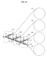
- the printer apparatus may include a first recording paper feeding part 130, a second recording paper feeding part 230, and a third recording paper feeding part 330, which have substantially the same configuration as the recording paper feeding part 30 described above and are cascade-connected. That is, a printing part 10 (not shown in FIG. 14 ) is connected to a delivery port 33 of the first recording paper feeding part 130, a second feed port 32 of the first recording paper feeding part 130 is connected to a delivery port 33 of the second recording paper feeding part 230, and a second feed port 32 of the second recording paper feeding part 230 is connected to a delivery port 33 of the third recording paper feeding part 330.
- First recording paper 101 is inserted into a first feed port 31 of the first recording paper feeding part 130
- second recording paper 102 is inserted into a first feed port 31 of the second recording paper feeding part 230
- third recording paper 103 is inserted into a first feed port 31 of the third recording paper feeding part 330
- fourth recording paper 104 is inserted into the second feed port 32 of the third recording paper feeding part 330.
- the printing part 10 may perform a printing operation on four different types of recording paper; namely, the first recording paper 101, the second recording paper 102, the third recording paper 103, and the fourth recording paper 104.
- the number of types of recording paper on which printing may be performed by the printing part 10 may be further increased by increasing the number of recording paper feeding parts 30 provided in the printer apparatus.
- a recording paper feeding part having a configuration similar to that of the recording paper feeding part 30 may be connected to the first feed port 31 of the first recording paper feeding part 130, and two more recording paper feeding parts having configurations similar to that of the recording paper feeding part 30 may be connected to the first feed port 31 and the second feed port 32 of the recording paper feeding part connected to the first recording paper feeding part 130. Further, a recording paper feeding part having a configuration similar to that of the recording paper feeding part 30 may be connected to the first feed port 31 of the second recording paper feeding part 230. In this way, printing may be performed on eight different sets of recording paper, for example. Note that the number of different sets of recording paper on which printing may be performed by the printing part 10 may be increased further by increasing the number of recording paper feeding parts that are cascade-connected.
Landscapes
- Physics & Mathematics (AREA)
- General Physics & Mathematics (AREA)
- Handling Of Sheets (AREA)
- Handling Of Continuous Sheets Of Paper (AREA)
Abstract
Description
- The present invention relates to a printer apparatus and a printer apparatus control method.
- Printers for issuing receipts are widely used in various applications including cash registers, Automated Teller Machines (ATM), and Cash Dispensers (CD), for example. Such printers are configured to issue a receipt by conveying a recording sheet such as thermal recording paper that is wound into a roll, printing objects such as characters on the recording sheet using a print head, and conveying the recording sheet up to a predetermined length so that the recording sheet may be cut at the predetermined length by a cutter (See, e.g., Japanese Laid-Open Patent Publication No.
2003-19845 2007-130842 - There is a demand for a printer apparatus that is capable of printing on different sets of recording paper so that a printer apparatus may not have to be provided for each set of recording paper.
- However, when measures are implemented to enable a printer apparatus to print on multiple sets of recording paper, the printer apparatus may be enlarged or the structure of the printer apparatus may be complicated. In turn, the price of the printer apparatus may increase and the printer apparatus may be prone to failure and defects, for example. Accordingly, a printer apparatus that is capable of printing on different sets of recording paper while having a compact and simple structure is desired.
- According to one embodiment of the present invention, a printer apparatus is provided that includes a printing part including a platen roller and a print head for printing objects onto a recording sheet, and a feeding part configured to feed the recording sheet to the printing part. The feeding part includes a first feed port and a second feed port for feeding the recording sheet, a first roller for conveying a first recording sheet fed through the first feed port, a second roller for conveying a second recording sheet fed through the second feed port, a delivery port for feeding the first recording sheet conveyed by the first roller and the second recording sheet conveyed by the second roller, a tension member having elasticity, a third roller rotatably connected to the tension member and being pressed toward the first roller by the elasticity of the tension member, and a fourth roller rotatably connected to the tension member and being pressed toward the second roller by the elasticity of the tension member.
- According to another embodiment of the present invention, a control method is provided for controlling a printer apparatus including a printing part that includes a print head and a platen roller driven by a printing part motor, and a feeding part for feeding a recording sheet to the printing part, the feeding part including a plurality of feed ports for feeding different recording sheets, a first roller for conveying a first recording sheet fed through a first feed port, a second roller for conveying a second recording sheet fed through a second feed port, a tension member having elasticity, a third roller rotatably connected to the tension member, and a fourth roller rotatably connected to the tension member. The control method includes, when switching the recording sheet subject to printing at the printing part from the first recording sheet to the second recording sheet, stopping rotation of the printing part motor while the first recording sheet is held between the print head and the platen roller, rotating the second roller and conveying the second recording sheet toward the printing part while the first recording sheet is held between the print head and the platen roller, and rotating the printing part motor and releasing the first recording sheet from the print head and the platen roller when the second recording sheet is conveyed to a predetermined position.
- According to an aspect of the present invention, a printer apparatus capable of printing on different recording sheets and having a compact and simple structure may be provided.
-
-
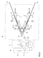
FIG. 1 illustrates a configuration of a printer apparatus according to a first embodiment of the present invention; -
FIG. 2 illustrates a first modified example of the printer apparatus according to the first embodiment; -
FIG. 3 illustrates a second modified example of the printer apparatus according to the first embodiment; -
FIG. 4 illustrates a third modified example of the printer apparatus according to the first embodiment; -
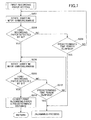
FIG. 5 is a flowchart illustrating exemplary process steps of a control method for controlling the printer apparatus according to the first embodiment; -
FIG. 6 is a flowchart illustrating a subroutine of the control method for controlling the printer apparatus according to the first embodiment; -
FIG. 7 is a flowchart illustrating another subroutine of the control method for controlling the printer apparatus according to the first embodiment; -
FIG. 8 is a flowchart illustrating further process steps of the control method for controlling the printer apparatus according to the first embodiment; -
FIG. 9 is a flowchart illustrating further process steps of the control method for controlling the printer apparatus according to the first embodiment; -
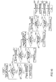
FIG. 10 is a flowchart illustrating further process steps of the control method for controlling the printer apparatus according to the first embodiment; -
FIG. 11 illustrates an operation state of the printer apparatus according to the first embodiment; -
FIG. 12 illustrates another operation state of the printer apparatus according to the first embodiment; -
FIG. 13 illustrates a preferred arrangement of components of the printer apparatus according to the first embodiment; and -
FIG. 14 illustrates a configuration of a printer apparatus according to a second embodiment of the present invention. - In the following, embodiments of the present invention are described with reference to the accompanying drawings. Note that the same or corresponding features shown in more than one of the drawings may be given the same reference numerals and their descriptions may be omitted.
- A printer apparatus according to a first embodiment of the present invention is described below. As illustrated in
FIG. 1 , the printer apparatus according to the first embodiment includes aprinting part 10, acutter part 20, and a recordingpaper feeding part 30 that is capable of feeding two different sets of recording paper to theprinting part 10. Note that recording paper is an example of a recording sheet. - The
printing part 10 includes athermal head 11, aplaten roller 12, aprinting part motor 13, and agear 14. Thethermal head 11 is a print head for printing objects on recording paper. Thethermal head 11 is configured to print objects on recording paper that is held between thethermal head 11 and theplaten roller 12. Theprinting part motor 13 is a motor for rotating theplaten roller 12 via thegear 14. When theprinting part motor 13 is rotated, recording paper may be conveyed toward thecutter part 20. Note that although not illustrated, theprinting part motor 13 and thegear 14 may have gear teeth. - The
cutter part 20 includes astationary blade 21 and amovable blade 22. By moving themovable blade 22 toward thestationary blade 21, recording paper having objects printed by theprinting part 10 may be cut. - The recording
paper feeding part 30 includes afirst roller 41, asecond roller 42, athird roller 43, afourth roller 44, aconveying motor 50,gears tension member 60, a first sensor (S1) 71, a second sensor (S2) 72, a third sensor (S3) 73, a fourth sensor (S4) 74, and a fifth sensor (S5) 75. Note that although not illustrated, thegears - Two types of recording paper; namely,
first recording paper 101 andsecond recording paper 102 may be fed to the recordingpaper feeding part 30. When feeding recording paper to the recordingpaper feeding part 30, thefirst recording paper 101 may be inserted into afirst feed port 31 from a first feeding route R1, and thesecond recording paper 102 may be inserted into asecond feed port 32 from a second feeding route R2. - The
tension member 60 has spring properties and may be made of a metallic material having elasticity, for example. Thetension member 60 includes anend part 61 arranged at the first feeding route R1 side where thefirst recording paper 101 is fed, and anend part 62 arranged at the second feeding route R2 side where thesecond recording paper 102 is fed. Theend parts tension member 60 has spring properties. That is, thetension member 60 is configured to exert a restoring force urging theend part 61 and theend part 62 toward each other. - The
third roller 43 and thefourth roller 44 are rotatably connected to thetension member 60. Aroller connection part 63 is arranged at theend part 61 side of thetension member 60, and thethird roller 43 is rotatably connected to theroller connection part 63. Aroller connection part 64 is arranged at theend part 62 side of thetension member 60, and thefourth roller 44 is rotatably connected to theroller connection part 64. Thethird roller 43 and thefourth roller 44 are thus arranged at the outer sides of thefirst roller 41 and thesecond roller 42, respectively. In this way, thethird roller 43 may be pressed toward thefirst roller 41 and thefourth roller 44 may be pressed toward thesecond roller 42 by the restoring force of thetension member 60. - The conveying
motor 50 is a motor for conveying thefirst recording paper 101 and thesecond recording paper 102 within the recordingpaper feeding part 30. Thefirst recording paper 101 may be conveyed by rotating thefirst roller 41 via thegear 51, and thesecond recording paper 102 may be conveyed by rotating thesecond roller 42 via thegear 52. - The
first recording paper 101 that is fed to the recordingpaper feeding part 30 is inserted from the first feeding route R1 into theend part 61 side of thetension member 60 forming thefirst feed port 31 and is held between thefirst roller 41 and thethird roller 43. When the conveyingmotor 50 is rotated counterclockwise in such a state, thegear 51 rotates clockwise, thefirst roller 41 rotates counterclockwise, and thefirst recording paper 101 is conveyed toward theprinting part 10 side within the recordingpaper feeding part 30. In this case, thethird roller 43, which is connected to thefirst roller 41 via thefirst recording paper 101, rotates clockwise. - The
second recording paper 102 that is fed to the recordingpaper feeding part 30 is inserted from the second feeding route R2 into theend part 62 side of thetension member 60 forming thesecond feed port 32 and is held between thesecond roller 42 and thefourth roller 44. When the conveyingmotor 50 is rotated clockwise in such a state, thegear 51 rotates counterclockwise, thesecond roller 42 rotates clockwise, and thesecond recording paper 102 is conveyed toward theprinting part 10. In this case, thefourth roller 44 connected to thesecond roller 42 via thesecond recording paper 102 rotates counterclockwise. - To perform printing on the
first recording paper 101 at theprinting part 10, the conveyingmotor 50 is rotated counterclockwise so that thefirst recording paper 101 at the recordingpaper feeding part 30 may be conveyed further toward theprinting part 10. In this way, thefirst recording paper 101 is conveyed to theprinting part 10 via adelivery port 33 and held between thethermal head 11 and theplaten roller 12 of theprinting part 10, and in such a state, theprinting part motor 13 is rotated counterclockwise. When theprinting part motor 13 is rotated counterclockwise, thegear 14 rotates clockwise and theplaten roller 12 rotates counterclockwise. In this way, thefirst recording paper 101 may be subject to printing by thethermal head 11 while being conveyed toward thecutter part 20. Thefirst recording paper 101 conveyed to thecutter part 20 may then be cut at a desired length by thestationary blade 21 and themovable blade 22. - To perform printing on the
second recording paper 102 at theprinting part 10, the conveyingmotor 50 is rotated clockwise so that thesecond recording paper 102 at the recordingpaper feeding part 30 may be conveyed further toward theprinting part 10. In this way, thesecond recording paper 102 is conveyed to theprinting part 10 via thedelivery port 33 and held between thethermal head 11 and theplaten roller 12 of theprinting part 10, and in such a state, theprinting part motor 13 is rotated counterclockwise. When theprinting part motor 13 is rotated counterclockwise, thegear 14 rotates clockwise and theplaten roller 12 rotates counterclockwise. In this way, thesecond recording paper 102 may be subject to printing by thethermal head 11 while being conveyed toward thecutter part 20. Thesecond recording paper 102 conveyed to thecutter part 20 may then be cut at a desired length by thestationary blade 21 and themovable blade 22. - In the following, modified examples of the printer apparatus are described.
- A metallic material forming a
tension member 60 of a printer apparatus as illustrated inFIG. 2 does not have a restoring force as described above, but atorsion coil spring 66 is arranged at a center portion of thetension member 60. Thetorsion coil spring 66 may exert a restoring force urging theend part 61 and theend part 62 of thetension member 60 toward each other, for example. - Alternatively, as illustrated in
FIG. 3 , acompression coil spring 67 may be arranged at the center portion of thetension member 60 of the printer apparatus. Thecompression coil spring 67 may exert a restoring force urging theend part 61 and theend part 62 of thetension member 60 toward each other, for example. - In another example, as illustrated in
FIG. 4 , two conveying motors may be provided at the printer apparatus. That is, a first conveying motor 55 and a second conveyingmotor 56 may be provided instead of the single conveyingmotor 50 illustrated inFIG. 1 . The first conveying motor 55 is for conveying thefirst recording paper 101 that is inserted into thefirst feed port 31, and the second conveyingmotor 56 is for conveying thesecond recording paper 102 that is inserted into thesecond feed port 32. - By rotating the first conveying motor 55 counterclockwise, the
first roller 41 may be rotated counterclockwise via thegear 51 and thefirst recording paper 101 may be conveyed toward theprinting part 10. By rotating the second conveyingmotor 56 clockwise, thesecond roller 42 may be rotated clockwise via thegear 52 and thesecond recording paper 102 may be conveyed toward theprinting part 10. - In the following, a method for controlling the printer apparatus according to the first embodiment is described.
- Referring, to
FIG. 5 , an initialization operation; namely, recording paper setting operations of the printer apparatus are described below. In the flowcharts provided hereunder, thefirst sensor 71 through thefifth sensor 75 are described as "S1" through "S5". - In step S102, whether recording paper is detected by the
fourth sensor 74 or thefifth sensor 75 is determined. If recording paper is detected by thefourth sensor 74 or thefifth sensor 75; namely, if thefirst recording paper 101 is detected by thefourth sensor 74 or thesecond recording paper 102 is detected by thefifth sensor 75, the operation proceeds to step S104. On the other hand, if recording paper is not detected by thefourth sensor 74 and thefifth sensor 75; namely, if thefirst recording paper 101 is not detected by thefourth sensor 74 and thesecond recording paper 102 is not detected by thefifth sensor 75, it is determined that the printer apparatus is in a standby state. - Next, in step S104, whether the
second recording paper 102 is detected by thefifth sensor 75 is determined. If thesecond recording paper 102 is detected by thefifth sensor 75, the operation proceeds to step S106. On the other hand, if thesecond recording paper 102 is not detected by thefifth sensor 75, the operation proceeds to step S108. - Next, in step S106, a second recording paper setting operation is performed. The second recording paper setting operation is described in detail below.
- Next, in step S108, whether the
first recording paper 101 is detected by thefourth sensor 74 is determined. If thefirst recording paper 101 is detected by thefourth sensor 74, the operation proceeds to step S110. On the other hand, if thefirst recording paper 101 is not detected by thefourth sensor 74, the second recording paper setting operation is completed and the initialization operation is ended. - Next, in step S110, a first recording paper setting operation is performed. The first recording paper setting operation is described in detail below. After the first recording paper setting operation or the second recording paper setting operation is completed, the initialization operation is ended.
- In the following, the second recording paper setting operation of step S106 in
FIG. 5 is described with reference toFIG. 6 . - In step S202, the conveying
motor 50 is rotated clockwise. As a result, thesecond roller 42 rotates clockwise and thesecond recording paper 102 is conveyed toward thethird sensor 73. Note that even if thefirst roller 41 also rotates clockwise, thefirst recording paper 101 is not conveyed in the case where therecording paper 101 is not held between thefirst roller 41 and thethird roller 43. - Next, in step S204, whether the
second recording paper 102 is detected by thethird sensor 73 is determined. If thesecond recording paper 102 is detected by thethird sensor 73, the operation proceeds to step S208. On the other hand, if thesecond recording paper 102 is not detected by thethird sensor 73, the operation proceeds to step S206. - Next, in step S206, whether a predetermined time period has elapsed after the rotation of the conveying
motor 50 is determined. If the predetermined time period has elapsed, it is determined that a jam error has occurred and an unjamming process is performed. On the other hand, if it is determined that the predetermined time period has not yet elapsed, steps S202 and S204 are repeated. - If the second recording paper is detected by the
third sensor 73, in step S208, the conveyingmotor 50 is further rotated clockwise. As a result, thesecond roller 42 rotates clockwise and thesecond recording paper 102 is conveyed toward thefirst sensor 71. - Next, in step S210, whether the
second recording paper 102 is detected by thefirst sensor 71 is determined. If thesecond recording paper 102 is detected by thefirst sensor 71, the operation proceeds to step S214. On the other hand, if thesecond recording paper 102 is not detected by thefirst sensor 71, the operation proceeds to step S212. - In step S212, whether a predetermined time period has elapsed after the conveying
motor 50 has been rotated clockwise in step S208 is determined. If the predetermined time period has elapsed, it is determined that a jam error has occurred and an unjamming process is performed. On the other hand, if it is determined that the predetermined time period has not yet elapsed, steps S208 and S210 are repeated. - In step S214, the
second recording paper 102 is conveyed for a predetermined distance. That is, the conveyingmotor 50 is further rotated clockwise to convey thesecond recording paper 102. Note that the conveying distance of thesecond recording paper 102 is arranged to be an adequately long distance such that thesecond recording paper 102 may still be held between thesecond roller 42 and thefourth roller 44 even when the first recording paper setting operation is performed as described below. - By performing the above process steps, the process illustrated in
FIG. 6 ; namely, the second recording paper setting operation of step S106 inFIG. 5 , is completed. - In the following, the first recording paper setting operation of step S110 in
FIG. 5 is described with reference toFIG. 7 . - In step S302, the conveying
motor 50 is rotated counterclockwise. As a result, thefirst roller 41 rotates counterclockwise and thefirst recording paper 101 is conveyed toward thesecond sensor 72. Note that thesecond roller 42 also rotates counterclockwise in this case, and thesecond recording paper 102 that is held between thesecond roller 42 and thefourth roller 44 is conveyed backward in an opposite direction away from theprinting part 10. - Next, in step S304, whether the
first recording paper 101 is detected by thesecond sensor 72 is determined. If thefirst recording paper 101 is detected by thesecond sensor 72, the operation proceeds to step S308. On the other hand, if thefirst recording paper 101 is not detected by thesecond sensor 72, the operation proceeds to step S306. - In step S306, whether a predetermined time period has elapsed after the conveying
motor 50 has been rotated counterclockwise is determined. If the predetermined time period has elapsed, it is determined that a jam error has occurred and an unjamming process is performed. On the other hand, if it is determined that the predetermined time period has not yet elapsed, steps S302 and S304 are repeated. - If the first recording paper is detected by the
second sensor 72, in step S308, the conveyingmotor 50 is further rotated counterclockwise. As a result, thefirst recording paper 101 is conveyed toward thefirst sensor 71. Note that in this step, thesecond recording paper 102 is moved backward by thesecond roller 42 so that thesecond recording paper 102 would not be detected by thefirst sensor 71. The conveying distance of thesecond recording paper 102 in step S212 ofFIG. 6 is set up such that thesecond recording paper 102 would not be detected by thefirst sensor 71. - Next, in step S310, whether the
first recording paper 101 is detected by thefirst sensor 71 is determined. If thefirst recording paper 101 is detected by thefirst sensor 71, the operation proceeds to step S314. On the other hand, if thefirst recording paper 101 is not detected by thefirst sensor 71, the operation proceeds to step S312. - In step S312, whether a predetermined time period has elapsed after the conveying
motor 50 has been rotated counterclockwise in step S308 is determined. If the predetermined time period has elapsed, it is determined that a jam error has occurred and an unjamming process is performed. On the other hand, if it is determined that the predetermined time period has not yet elapsed, steps S308 and S310 are repeated. - In step S314, the
first recording paper 101 is conveyed for a predetermined distance. That is, the conveyingmotor 50 is further rotated counterclockwise to convey thefirst recording paper 101 to a contact point between thethermal head 11 and theplaten roller 12. Note that thesecond recording paper 102 is held between thesecond roller 42 and thefourth roller 44 in this case. - By performing the above process steps, the process illustrated in
FIG. 7 ; namely, the first recording paper setting operation of step S110 inFIG. 5 , is completed. - In the following, a printing operation on the recording paper; namely, the
first recording paper 101 or that second recording paper, performed after completing the initialization operation ofFIG. 5 is described. -
FIG. 8 illustrates a printing operation on thefirst recording paper 101. - In step S402, the
printing part motor 13 is rotated counterclockwise. As a result, theplaten roller 12 rotates counterclockwise via thegear 14 and thefirst recording paper 101 is inserted between thethermal head 11 and theplaten roller 12. Hereinafter, thefirst recording paper 101 is conveyed by rotating theprinting part motor 13 counterclockwise. - Next, in step S404, rotation of the conveying
motor 50 is stopped because thefirst recording paper 101 can be conveyed by the counterclockwise rotation of theprinting part motor 13 even without the counterclockwise rotation of the conveyingmotor 50. Note that at this point, even if thesecond recording paper 102 is interposed between thesecond roller 42 and thefourth roller 44, by stopping the rotation of the conveyingmotor 50, thesecond recording paper 102 may not be moved any further in the backward direction. - Next, in step S406, printing is performed on the
first recording paper 101 while thefirst recording paper 101 is conveyed by rotating theprinting part motor 13 counterclockwise. - Next, in step S408, after the printing on the
first recording paper 101 is completed, thefirst recording paper 101 is cut at thecutter part 20. In turn, the printing operation ofFIG. 8 is ended. - By performing the above process, the printing operation on the
first recording paper 101 is completed. - In the following, a printing operation on the
second recording paper 102 performed after the initialization process ofFIG. 5 is described with reference toFIG. 9 . - In step S502, the conveying
motor 50 is rotated clockwise. As a result, thesecond recording paper 102 is conveyed toward thefirst sensor 71. - Next, in step S504, whether the
second recording paper 102 is detected by thefirst sensor 71 is determined. If thesecond recording paper 102 is detected by thefirst sensor 71, the operation proceeds to step S508. On the other hand, if thesecond recording paper 102 is not detected by thefirst sensor 71, the operation proceeds to step S506. - In step S506, whether a predetermined time period has elapsed after rotation of the conveying
motor 50 in step S502 is determined. If the predetermined time period has elapsed, it is determined that a jam error has occurred and an unjamming process is performed. On the other hand, if it is determined that the predetermined time period has not yet elapsed, steps S502 and S504 are repeated. - In step S508, the
second recording paper 102 is conveyed for a predetermined distance. That is, the conveyingmotor 50 is further rotated clockwise to convey thesecond recording paper 102 to a contact point between thethermal head 11 and theplaten roller 12. Note that at this point, thefirst recording paper 101 may be interposed between thefirst roller 41 and thethird roller 43. - Next, in step S510, the
printing part motor 13 is rotated counterclockwise. As a result, theplaten roller 12 is rotated counterclockwise via thegear 14 and thesecond recording paper 102 is inserted between thethermal head 11 and theplaten roller 12. Hereinafter, thesecond recording paper 102 is conveyed by rotating theprinting part motor 13 counterclockwise. - Next, in step S512, the rotation of the conveying
motor 50 is stopped because thesecond recording paper 102 can be conveyed by the counterclockwise rotation of theprinting part motor 13 without rotating the conveyingmotor 50. Note that at this point, thefirst recording paper 101 interposed between thefirst roller 41 and thethird roller 43 may not be moved any further because the rotation of the conveyingmotor 50 is stopped. - Next, in step S514, printing is performed on the
second recording paper 102 while thesecond recording paper 102 is conveyed. - Next, in step S516, after the printing on the
second recording paper 102 is completed, thesecond recording paper 102 is cut at thecutter part 20. In turn, the printing operation ofFIG. 9 is ended. - By performing the above process, the printing operation on the
second recording paper 102 is completed. Note that when performing a printing operation on thesecond recording paper 102 in a case where the first recording paper setting operation is not performed in the initialization operation ofFIG. 5 ; namely, in the case where step S110 ofFIG. 5 is not performed, steps S502 through S508 ofFIG. 9 may be omitted and only steps S510 through S516 of the above operation are performed. - In the following, recording paper switching and printing operations are described with reference to
FIG. 10 . That is, exemplary operations for switching from thefirst recording paper 101 to thesecond recording paper 102 after the printing operation on thefirst recording paper 101 ofFIG. 8 has been completed, and performing a printing operation on thesecond recording paper 102 are described below. - Rolled paper may be used as the
first recording paper 101 and thesecond recording paper 102.FIG. 11 illustrates a state where thefirst recording paper 101 is conveyed by thefirst roller 41 and thethird roller 43. When a printing operation is performed on thefirst recording paper 101, the printer apparatus transition from a state as illustrated inFIG. 11 to a state as illustrated inFIG. 12 . As illustrated inFIG. 12 , theend part 61 of thetension member 60 is raised by thefirst recording paper 101 conveyed by theplaten roller 12, and the distance between theend part 61 and theend part 62 of thetension member 60 is widened. Therefore, thethird roller 43 that has been in contact with thefirst roller 41 via thefirst recording paper 101 moves away from thefirst roller 41, and thefirst recording paper 101 ceases to be in contact with thefirst roller 41. When thefirst roller 41 and thethird roller 43 move away from one another as illustrated inFIG. 12 , thefirst recording paper 101 is conveyed by theprinting part motor 13, and thefirst roller 41 ceases to have a contributory effect on conveying thefirst recording paper 101. - Similar transitions apply in the case of printing on the
second recording paper 102. That is, when a printing operation is performed on thesecond recording paper 102, theend part 62 of thetension member 60 is raised by thesecond recording paper 102 conveyed by theplaten roller 12, and the distance between theend part 61 and endpart 62 of thetension member 60 is widened. Therefore, thefourth roller 44 that has been in contact with thesecond roller 42 via thesecond recording paper 102 moves away from thesecond roller 42, and thesecond recording paper 102 ceases to be in contact with thesecond roller 42. - The operations illustrated in
FIG. 10 utilize the above-described features of the printer apparatus of the present embodiment. - First, while in the state as illustrated in
FIG. 12 , in step S602, excitation of theprinting part motor 13 is stopped. In this way, the rotation of theprinting part motor 13 is stopped and thefirst recording paper 101 remains held between thethermal head 11 and theplaten roller 12. - Next, in step S604, whether the
second recording paper 102 is detected by thefifth sensor 75 is determined. If thesecond recording paper 102 is detected by thefifth sensor 75, the operation proceeds to step S610. On the other hand, if thesecond recording paper 102 is not detected by thefifth sensor 75, the operation proceeds to step S606. - In step S606, whether a predetermined time period has elapsed after the excitation of the
printing part motor 13 has been stopped is determined. If it is determined that the predetermined time period has elapsed, the operation proceeds to step S608. If it is determined that the predetermined time period has not yet elapsed, step S604 is repeated. - In step S608, the conveying
part motor 13 is turned off, and an error process is performed thereafter. - In step S610, the conveying
motor 50 is rotated clockwise. As a result, thesecond roller 42 rotates clockwise and thesecond recording paper 102 is conveyed toward thethird sensor 73. Note that although thefirst roller 41 rotates clockwise in this case, because thethird roller 43 is raised by thefirst recording paper 101 as illustrated inFIG. 12 , thefirst roller 41 and thethird roller 43 are set apart from each other, and thefirst roller 41 is not in contact with thefirst recording paper 101. Therefore, thefirst roller 41 may be prevented from applying a force to thefirst recording paper 101 even when thefirst roller 41 is rotated. - Next, in step S612, whether the
second recording paper 102 is detected by thethird sensor 73 is determined. If thesecond recording paper 102 is detected by thethird sensor 73, the operation proceeds to step S616. On the other hand, if thesecond recording paper 102 is not detected by thethird sensor 73, the operation proceeds to step S614. - In step S614, whether a predetermined time period has elapsed after the conveying
motor 50 has been rotated clockwise in step S610 is determined. If the predetermined time period has elapsed, it is determined that an error has occurred and an error process is performed. On the other hand, if it is determined that the predetermined time period has not yet elapsed, steps S610 and S612 are repeated. - In step S616, the
printing part motor 13 is rotated clockwise (inFIG. 10 , rotating theprinting part motor 13 clockwise is referred to as "unrotate printing part motor") and the conveyingmotor 50 is further rotated clockwise. As a result, thefirst recording paper 101 is moved away from thethermal head 11 and theplaten roller 12 and is released from thethermal head 11 and theplaten roller 12. That is, thefirst recording paper 101 is moved backward in a direction opposite the direction toward thecutter part 20. Meanwhile, thesecond recording paper 102 is conveyed toward thefirst sensor 71. - In step S618, whether the
first recording paper 101 is detected by thefirst sensor 71 is determined. If thefirst recording paper 101 is detected by thefirst sensor 71, the operation proceeds to step S620. On the other hand, if thefirst recording paper 101 is not detected by thefirst sensor 71, this means that thefirst recording paper 101 has been moved back to a position such that it would not be detected by thefirst sensor 71, and the operation proceeds to step S622. - In step S620, a determination is made as to whether a predetermined time period has elapsed after the conveying
motor 50 has been rotated clockwise in step S616 is determined. If the predetermined time period has elapsed, it is determined that an error has occurred and an error process is performed. On the other hand, if it is determined that the predetermined time period has not yet elapsed, steps S616 and S618 are repeated. - In step S622, the conveying
motor 50 is further rotated clockwise. As a result, thesecond recording paper 102 is conveyed toward thefirst sensor 71. - Next, in step S624, whether the second recording paper is detected by the
first sensor 71 is determined. If the second recording paper is detected by thefirst sensor 71, the operation proceeds to step S628. On the other hand, if the second recording paper is not detected by thefirst sensor 71, the operation proceeds to step S626. - In step S626, whether a predetermined time period has elapsed after the conveying
motor 50 has been rotated clockwise in step S622 is determined. If the predetermined time period has elapsed, it is determined that an error has occurred and an error process is performed. On the other hand, if it is determined that the predetermined time period has not yet elapsed, steps S622 and S624 are repeated. - If the
second recording paper 102 is detected by thefirst sensor 71, in step S628, the conveyingmotor 50 is further rotated clockwise while theprinting part motor 13 is rotated counterclockwise. As a result, theplaten roller 12 is rotated counterclockwise via thegear 14, and thesecond recording paper 102 is inserted between thethermal head 11 and theplaten roller 12. Hereinafter, thesecond recording paper 102 is conveyed by rotating theprinting part motor 13 counterclockwise. - Next, in step S630, rotation of the conveying
motor 50 is stopped because thesecond recording paper 102 may be conveyed by the counterclockwise rotation of theprinting part motor 13 without the clockwise rotation of the conveyingmotor 50. At this point, thefirst recording paper 101 is interposed between thefirst roller 41 and thethird roller 43, and by stopping the rotation of the conveyingmotor 50, thefirst recording paper 101 may not be moved further. - In an embodiment, as illustrated in
FIG. 13 , thecutter part 20, thethermal head 11, theplaten roller 12, thefirst sensor 71, and thesecond sensor 72 are arranged such that a length L1 between thecutter part 20 and theterminal head 11/platen roller 12, a length L2 between theterminal head 11/platen roller 12 and the first sensor (S1) 71, and a length L3 between the first sensor (S1) 71 and the second sensor (S2) 72 satisfy the following relationship: (L1+L2) < L3. Note that in the case where thefirst recording paper 101 is not detected by the second sensor (S2) 72, the conveyingmotor 50 may be rotated counterclockwise and thefirst recording paper 101 may be conveyed to a position at which it would not be detected by the second sensor (S2) 72. - Next, in step S632, printing is performed on the
second recording paper 102 by thethermal head 11 while thesecond recording paper 102 is conveyed by further rotating theprinting part motor 13. - Next, in step S634, after the printing on the
second recording paper 102 has been completed, thesecond recording paper 102 is cut at thecutter part 20. In this way, the operations for switching from thefirst recording paper 101 to thesecond recording paper 102 and printing on thesecond recording paper 102 is ended. - Note that a method for controlling a printer apparatus according to an embodiment of the present invention has been described above. However, the present invention encompasses other numerous variations and modifications of the above control method.
- In the following, a second embodiment of the present invention is described. A printer apparatus according to the second embodiment includes a plurality of the recording
paper feeding parts 30 described above, and afirst feed port 31 or asecond feed port 32 of one recordingpaper feeding part 30 is connected to adelivery port 33 of another recordingpaper feeding part 30. - For example, as illustrated in
FIG. 14 , the printer apparatus according to the present embodiment may include a first recordingpaper feeding part 130, a second recordingpaper feeding part 230, and a third recordingpaper feeding part 330, which have substantially the same configuration as the recordingpaper feeding part 30 described above and are cascade-connected. That is, a printing part 10 (not shown inFIG. 14 ) is connected to adelivery port 33 of the first recordingpaper feeding part 130, asecond feed port 32 of the first recordingpaper feeding part 130 is connected to adelivery port 33 of the second recordingpaper feeding part 230, and asecond feed port 32 of the second recordingpaper feeding part 230 is connected to adelivery port 33 of the third recordingpaper feeding part 330. -
First recording paper 101 is inserted into afirst feed port 31 of the first recordingpaper feeding part 130,second recording paper 102 is inserted into afirst feed port 31 of the second recordingpaper feeding part 230,third recording paper 103 is inserted into afirst feed port 31 of the third recordingpaper feeding part 330, andfourth recording paper 104 is inserted into thesecond feed port 32 of the third recordingpaper feeding part 330. - According to an aspect of the present embodiment, the
printing part 10 may perform a printing operation on four different types of recording paper; namely, thefirst recording paper 101, thesecond recording paper 102, thethird recording paper 103, and thefourth recording paper 104. Note that the number of types of recording paper on which printing may be performed by theprinting part 10 may be further increased by increasing the number of recordingpaper feeding parts 30 provided in the printer apparatus. - For example, a recording paper feeding part having a configuration similar to that of the recording
paper feeding part 30 may be connected to thefirst feed port 31 of the first recordingpaper feeding part 130, and two more recording paper feeding parts having configurations similar to that of the recordingpaper feeding part 30 may be connected to thefirst feed port 31 and thesecond feed port 32 of the recording paper feeding part connected to the first recordingpaper feeding part 130. Further, a recording paper feeding part having a configuration similar to that of the recordingpaper feeding part 30 may be connected to thefirst feed port 31 of the second recordingpaper feeding part 230. In this way, printing may be performed on eight different sets of recording paper, for example. Note that the number of different sets of recording paper on which printing may be performed by theprinting part 10 may be increased further by increasing the number of recording paper feeding parts that are cascade-connected. - Although the present invention is described above with respect to certain illustrative embodiments, the present invention is not limited to these embodiments but encompasses numerous variations and modifications that may be made without departing from the spirit and scope of the present invention.
Claims (9)
- A printer apparatus comprising:a printing part (10) that includes a platen roller (12) and a print head (11) for printing objects onto a recording sheet (101, 102); anda feeding part (30) configured to feed the recording sheet to the printing part (10), the feeding part includinga first feed port (31) and a second feed port (32) for feeding the recording sheet;a first roller (41) for conveying a first recording sheet (101) fed through the first feed port (31);a second roller (32) for conveying a second recording sheet (102) fed through the second feed port (32);a delivery port (33) for feeding the first recording sheet conveyed by the first roller and the second recording sheet conveyed by the second roller;a tension member (60) having elasticity;a third roller (43) rotatably connected to the tension member (60) and being pressed toward the first roller (41) by the elasticity of the tension member; anda fourth roller (44) rotatably connected to the tension member (60) and being pressed toward the second roller (42) by the elasticity of the tension member.
- The printer apparatus as claimed in claim 1, wherein when switching the recording paper subject to printing at the printing part (10) from the first recording sheet (101) to the second recording sheet (102), a force is applied to the third roller (43) by the first recording sheet (101) in a direction urging the third roller (43) away from the first roller (41), and the second recording sheet (102) is conveyed toward the printing part (10) by the second roller (42) and the fourth roller (44) while the first roller (41) and the third roller (43) are set apart from each other.
- The printer apparatus as claimed in claim 1 or 2, wherein the tension member (60) is configured to exert a restoring force in a direction urging the third roller (43) and the fourth roller (44) toward each other.
- The printer apparatus as claimed in claim 1 or 2, wherein
the tension member (60) includes a spring (66, 67); and
the spring (66, 67) exerts a restoring force in a direction urging the third roller (43) and the fourth roller (44) toward each other. - The printer apparatus as claimed in any one of claims 1-4, wherein the first roller (41) and the second roller (42) are rotated by one conveying motor (50).
- The printer apparatus as claimed in any one of claims 1-5, wherein a plurality of the feeding parts (30) are arranged such that a feed port (31, 32) of one of the feeding parts (30) is connected to a delivery port (33) of another feeding part (30).
- A control method for controlling a printer apparatus including a printing part (10) that includes a print head (11) and a platen roller (12) driven by a printing part motor (13), and a feeding part (30) for feeding a recording sheet (101, 102) to the printing part, the feeding part including a plurality of feed ports (31, 32) for feeding different recording sheets (101, 102), a first roller (41) for conveying a first recording sheet (101) fed through a first feed port (31), a second roller (42) for conveying a second recording sheet (102) fed through a second feed port (32), a tension member (60) having elasticity, a third roller (43) rotatably connected to the tension member, and a fourth roller (44) rotatably connected to the tension member, the control method comprising:when switching the recording sheet subject to printing at the printing part (10) from the first recording sheet (101) to the second recording sheet (102), stopping rotation of the printing part motor (13) while the first recording sheet (101) is held between the print head (11) and the platen roller (12), rotating the second roller (42) and conveying the second recording sheet (102) toward the printing part (10) while the first recording sheet (101) is held between the print head (11) and the platen roller (12), and rotating the printing part motor (13) and releasing the first recording sheet (101) from the print head (11) and the platen roller (12) when the second recording sheet (102) is conveyed to a predetermined position.
- The control method as claimed in claim 7, wherein when the rotation of the printing part motor (13) is stopped while the first recording sheet (101) is held between the print head (11) and the platen roller (12), a force is applied to the third roller (43) by the first recording sheet (101) in a direction urging the third roller (43) away from the first roller (41), and the first roller (41) and the third roller (43) are set apart from each other.
- The printer apparatus as claimed in claim 7 or 8, wherein when printing is performed on the first recording sheet (101), a force is applied to the third roller (43) by the first recording sheet (101) in a direction urging the third roller (43) away from the first roller (41), and the first roller (41) and the third roller (43) are set apart from each other.
Applications Claiming Priority (1)
| Application Number | Priority Date | Filing Date | Title |
|---|---|---|---|
| JP2013019845A JP6018943B2 (en) | 2013-02-04 | 2013-02-04 | Printer device and printer device control method |
Publications (2)
| Publication Number | Publication Date |
|---|---|
| EP2762319A1 true EP2762319A1 (en) | 2014-08-06 |
| EP2762319B1 EP2762319B1 (en) | 2017-08-23 |
Family
ID=50000868
Family Applications (1)
| Application Number | Title | Priority Date | Filing Date |
|---|---|---|---|
| EP14152835.6A Not-in-force EP2762319B1 (en) | 2013-02-04 | 2014-01-28 | Printer apparatus and printer apparatus control method |
Country Status (4)
| Country | Link |
|---|---|
| US (1) | US9211740B2 (en) |
| EP (1) | EP2762319B1 (en) |
| JP (1) | JP6018943B2 (en) |
| CN (1) | CN103963490B (en) |
Cited By (2)
| Publication number | Priority date | Publication date | Assignee | Title |
|---|---|---|---|---|
| CN105437791A (en) * | 2015-12-14 | 2016-03-30 | 广州市宝比万像科技有限公司 | Printer |
| CN105564054A (en) * | 2015-12-14 | 2016-05-11 | 广州市宝比万像科技有限公司 | Printer operation control method |
Families Citing this family (8)
| Publication number | Priority date | Publication date | Assignee | Title |
|---|---|---|---|---|
| CN104210255B (en) * | 2014-08-26 | 2017-01-25 | 广州市宝比万像科技有限公司 | Printing machine |
| JP6520528B2 (en) * | 2015-07-29 | 2019-05-29 | セイコーエプソン株式会社 | Printing device |
| CN106476449B (en) * | 2015-09-02 | 2018-08-31 | 深圳市博思得科技发展有限公司 | The device and method that printer continues paper automatically |
| CN105500937B (en) * | 2015-12-14 | 2017-08-11 | 广州市宝比万像科技有限公司 | Printer |
| CN105459630B (en) * | 2015-12-14 | 2019-01-25 | 广州市宝比万像科技有限公司 | Printer |
| CN107128082B (en) * | 2016-02-29 | 2019-05-31 | 深圳市博思得科技发展有限公司 | A kind of printer automatic feeder and automatic continuous paper printer |
| CN107150916B (en) * | 2016-03-03 | 2019-06-04 | 山东新北洋信息技术股份有限公司 | A kind of binary channels paper feeding mechanism and laminated medium processing unit |
| WO2025196608A1 (en) * | 2024-03-18 | 2025-09-25 | System Ceramics S.P.A. | Apparatus and method for loading in continuous laminar material into a processing machine |
Citations (6)
| Publication number | Priority date | Publication date | Assignee | Title |
|---|---|---|---|---|
| DE2644087A1 (en) * | 1976-09-30 | 1978-04-06 | Brede Mako Apparate | CARD STRIP PRINTING MACHINE, IN PARTICULAR FOR TICKETS |
| EP0362976A2 (en) * | 1988-10-07 | 1990-04-11 | Klüssendorf Aktiengesellschaft | Device to feed web material to a treatment station |
| US5838354A (en) * | 1995-05-31 | 1998-11-17 | Olympus Optical Co., Ltd. | Image forming apparatus |
| WO2001030582A1 (en) * | 1999-10-29 | 2001-05-03 | La Poste (Exploitant Public) | Printing module for two printing substrates and distributors equipped with modules of this type |
| JP2003019845A (en) | 2001-07-09 | 2003-01-21 | Nagano Fujitsu Component Kk | Printer |
| JP2007130842A (en) | 2005-11-09 | 2007-05-31 | Fujitsu Component Ltd | Printer device |
Family Cites Families (6)
| Publication number | Priority date | Publication date | Assignee | Title |
|---|---|---|---|---|
| JPH01231728A (en) * | 1988-03-11 | 1989-09-18 | Alps Electric Co Ltd | Paper feeder |
| JP3794752B2 (en) * | 1996-04-23 | 2006-07-12 | オリンパス株式会社 | Image forming apparatus |
| JPH08324846A (en) * | 1995-06-02 | 1996-12-10 | Kubota Corp | Automatic paper feeding method and device for ticketing machine |
| KR100419349B1 (en) * | 2002-05-03 | 2004-02-21 | 코리아프린팅시스템 주식회사 | Guide apparatus of paper for mini printer |
| JP2004167931A (en) * | 2002-11-21 | 2004-06-17 | Canon Inc | Image recording device |
| JP4672731B2 (en) * | 2005-10-26 | 2011-04-20 | 三菱電機株式会社 | Printer device |
-
2013
- 2013-02-04 JP JP2013019845A patent/JP6018943B2/en not_active Expired - Fee Related
-
2014
- 2014-01-28 CN CN201410041125.9A patent/CN103963490B/en not_active Expired - Fee Related
- 2014-01-28 US US14/165,722 patent/US9211740B2/en not_active Expired - Fee Related
- 2014-01-28 EP EP14152835.6A patent/EP2762319B1/en not_active Not-in-force
Patent Citations (6)
| Publication number | Priority date | Publication date | Assignee | Title |
|---|---|---|---|---|
| DE2644087A1 (en) * | 1976-09-30 | 1978-04-06 | Brede Mako Apparate | CARD STRIP PRINTING MACHINE, IN PARTICULAR FOR TICKETS |
| EP0362976A2 (en) * | 1988-10-07 | 1990-04-11 | Klüssendorf Aktiengesellschaft | Device to feed web material to a treatment station |
| US5838354A (en) * | 1995-05-31 | 1998-11-17 | Olympus Optical Co., Ltd. | Image forming apparatus |
| WO2001030582A1 (en) * | 1999-10-29 | 2001-05-03 | La Poste (Exploitant Public) | Printing module for two printing substrates and distributors equipped with modules of this type |
| JP2003019845A (en) | 2001-07-09 | 2003-01-21 | Nagano Fujitsu Component Kk | Printer |
| JP2007130842A (en) | 2005-11-09 | 2007-05-31 | Fujitsu Component Ltd | Printer device |
Cited By (2)
| Publication number | Priority date | Publication date | Assignee | Title |
|---|---|---|---|---|
| CN105437791A (en) * | 2015-12-14 | 2016-03-30 | 广州市宝比万像科技有限公司 | Printer |
| CN105564054A (en) * | 2015-12-14 | 2016-05-11 | 广州市宝比万像科技有限公司 | Printer operation control method |
Also Published As
| Publication number | Publication date |
|---|---|
| US20140219699A1 (en) | 2014-08-07 |
| EP2762319B1 (en) | 2017-08-23 |
| US9211740B2 (en) | 2015-12-15 |
| JP2014151439A (en) | 2014-08-25 |
| JP6018943B2 (en) | 2016-11-02 |
| CN103963490B (en) | 2016-03-23 |
| CN103963490A (en) | 2014-08-06 |
Similar Documents
| Publication | Publication Date | Title |
|---|---|---|
| EP2762319A1 (en) | Printer apparatus and printer apparatus control method | |
| CN102673187B (en) | Recording medium cutting apparatus | |
| CN104290465A (en) | Printing apparatus and control method | |
| JP6264146B2 (en) | Transport device | |
| CN108973341A (en) | Printing device, Method of printing and print routine | |
| US9878866B2 (en) | Recording device and conveyance device | |
| EP2689936B1 (en) | Printer | |
| US9193555B2 (en) | Printer with paper skewing section positioned after manual cutter | |
| US9731923B2 (en) | Medium transport method, medium transport device, and image recording device | |
| US9738091B2 (en) | Thermal printer | |
| JP2006159427A (en) | Portable printer using print sheet while switching depending on use | |
| JP4937001B2 (en) | Printing device | |
| CN104169201B (en) | The control method of type printer and type printer | |
| JP2018070305A (en) | Discharging device and image forming apparatus | |
| US9521278B1 (en) | Magnetic data processing device and printing apparatus having the same | |
| CN104118218A (en) | Printer apparatus | |
| KR101399860B1 (en) | Apparatus for cutting crop of material | |
| JP5830390B2 (en) | Printer device and printer device control method | |
| JP2014104606A (en) | Printer control method and printer system | |
| JP2017159521A (en) | Printing device and printing method | |
| JP4849391B2 (en) | Printing device and automatic ticket vending machine | |
| JP2004291596A (en) | Medium processor | |
| EP3199362A1 (en) | Printer apparatus | |
| CN104029504B (en) | Printing Apparatus | |
| JP2013170023A (en) | Conveyance device and printer |
Legal Events
| Date | Code | Title | Description |
|---|---|---|---|
| PUAI | Public reference made under article 153(3) epc to a published international application that has entered the european phase |
Free format text: ORIGINAL CODE: 0009012 |
|
| 17P | Request for examination filed |
Effective date: 20140128 |
|
| AK | Designated contracting states |
Kind code of ref document: A1 Designated state(s): AL AT BE BG CH CY CZ DE DK EE ES FI FR GB GR HR HU IE IS IT LI LT LU LV MC MK MT NL NO PL PT RO RS SE SI SK SM TR |
|
| AX | Request for extension of the european patent |
Extension state: BA ME |
|
| R17P | Request for examination filed (corrected) |
Effective date: 20150202 |
|
| RBV | Designated contracting states (corrected) |
Designated state(s): AL AT BE BG CH CY CZ DE DK EE ES FI FR GB GR HR HU IE IS IT LI LT LU LV MC MK MT NL NO PL PT RO RS SE SI SK SM TR |
|
| 17Q | First examination report despatched |
Effective date: 20160926 |
|
| REG | Reference to a national code |
Ref country code: DE Ref legal event code: R079 Ref document number: 602014013361 Country of ref document: DE Free format text: PREVIOUS MAIN CLASS: B41J0015180000 Ipc: B41J0011480000 |
|
| RIC1 | Information provided on ipc code assigned before grant |
Ipc: B41J 15/18 20060101ALI20170113BHEP Ipc: B65H 20/02 20060101ALI20170113BHEP Ipc: B41J 11/48 20060101AFI20170113BHEP Ipc: G07B 1/00 20060101ALI20170113BHEP |
|
| GRAP | Despatch of communication of intention to grant a patent |
Free format text: ORIGINAL CODE: EPIDOSNIGR1 |
|
| INTG | Intention to grant announced |
Effective date: 20170301 |
|
| GRAS | Grant fee paid |
Free format text: ORIGINAL CODE: EPIDOSNIGR3 |
|
| GRAJ | Information related to disapproval of communication of intention to grant by the applicant or resumption of examination proceedings by the epo deleted |
Free format text: ORIGINAL CODE: EPIDOSDIGR1 |
|
| GRAL | Information related to payment of fee for publishing/printing deleted |
Free format text: ORIGINAL CODE: EPIDOSDIGR3 |
|
| GRAR | Information related to intention to grant a patent recorded |
Free format text: ORIGINAL CODE: EPIDOSNIGR71 |
|
| GRAA | (expected) grant |
Free format text: ORIGINAL CODE: 0009210 |
|
| INTC | Intention to grant announced (deleted) | ||
| INTG | Intention to grant announced |
Effective date: 20170713 |
|
| AK | Designated contracting states |
Kind code of ref document: B1 Designated state(s): AL AT BE BG CH CY CZ DE DK EE ES FI FR GB GR HR HU IE IS IT LI LT LU LV MC MK MT NL NO PL PT RO RS SE SI SK SM TR |
|
| REG | Reference to a national code |
Ref country code: GB Ref legal event code: FG4D |
|
| REG | Reference to a national code |
Ref country code: CH Ref legal event code: EP |
|
| REG | Reference to a national code |
Ref country code: AT Ref legal event code: REF Ref document number: 920900 Country of ref document: AT Kind code of ref document: T Effective date: 20170915 |
|
| REG | Reference to a national code |
Ref country code: IE Ref legal event code: FG4D |
|
| REG | Reference to a national code |
Ref country code: DE Ref legal event code: R096 Ref document number: 602014013361 Country of ref document: DE |
|
| REG | Reference to a national code |
Ref country code: FR Ref legal event code: PLFP Year of fee payment: 5 |
|
| REG | Reference to a national code |
Ref country code: NL Ref legal event code: MP Effective date: 20170823 |
|
| REG | Reference to a national code |
Ref country code: LT Ref legal event code: MG4D |
|
| REG | Reference to a national code |
Ref country code: AT Ref legal event code: MK05 Ref document number: 920900 Country of ref document: AT Kind code of ref document: T Effective date: 20170823 |
|
| PG25 | Lapsed in a contracting state [announced via postgrant information from national office to epo] |
Ref country code: NL Free format text: LAPSE BECAUSE OF FAILURE TO SUBMIT A TRANSLATION OF THE DESCRIPTION OR TO PAY THE FEE WITHIN THE PRESCRIBED TIME-LIMIT Effective date: 20170823 Ref country code: HR Free format text: LAPSE BECAUSE OF FAILURE TO SUBMIT A TRANSLATION OF THE DESCRIPTION OR TO PAY THE FEE WITHIN THE PRESCRIBED TIME-LIMIT Effective date: 20170823 Ref country code: NO Free format text: LAPSE BECAUSE OF FAILURE TO SUBMIT A TRANSLATION OF THE DESCRIPTION OR TO PAY THE FEE WITHIN THE PRESCRIBED TIME-LIMIT Effective date: 20171123 Ref country code: AT Free format text: LAPSE BECAUSE OF FAILURE TO SUBMIT A TRANSLATION OF THE DESCRIPTION OR TO PAY THE FEE WITHIN THE PRESCRIBED TIME-LIMIT Effective date: 20170823 Ref country code: LT Free format text: LAPSE BECAUSE OF FAILURE TO SUBMIT A TRANSLATION OF THE DESCRIPTION OR TO PAY THE FEE WITHIN THE PRESCRIBED TIME-LIMIT Effective date: 20170823 Ref country code: SE Free format text: LAPSE BECAUSE OF FAILURE TO SUBMIT A TRANSLATION OF THE DESCRIPTION OR TO PAY THE FEE WITHIN THE PRESCRIBED TIME-LIMIT Effective date: 20170823 Ref country code: FI Free format text: LAPSE BECAUSE OF FAILURE TO SUBMIT A TRANSLATION OF THE DESCRIPTION OR TO PAY THE FEE WITHIN THE PRESCRIBED TIME-LIMIT Effective date: 20170823 |
|
| PG25 | Lapsed in a contracting state [announced via postgrant information from national office to epo] |
Ref country code: GR Free format text: LAPSE BECAUSE OF FAILURE TO SUBMIT A TRANSLATION OF THE DESCRIPTION OR TO PAY THE FEE WITHIN THE PRESCRIBED TIME-LIMIT Effective date: 20171124 Ref country code: RS Free format text: LAPSE BECAUSE OF FAILURE TO SUBMIT A TRANSLATION OF THE DESCRIPTION OR TO PAY THE FEE WITHIN THE PRESCRIBED TIME-LIMIT Effective date: 20170823 Ref country code: LV Free format text: LAPSE BECAUSE OF FAILURE TO SUBMIT A TRANSLATION OF THE DESCRIPTION OR TO PAY THE FEE WITHIN THE PRESCRIBED TIME-LIMIT Effective date: 20170823 Ref country code: IS Free format text: LAPSE BECAUSE OF FAILURE TO SUBMIT A TRANSLATION OF THE DESCRIPTION OR TO PAY THE FEE WITHIN THE PRESCRIBED TIME-LIMIT Effective date: 20171223 Ref country code: ES Free format text: LAPSE BECAUSE OF FAILURE TO SUBMIT A TRANSLATION OF THE DESCRIPTION OR TO PAY THE FEE WITHIN THE PRESCRIBED TIME-LIMIT Effective date: 20170823 Ref country code: PL Free format text: LAPSE BECAUSE OF FAILURE TO SUBMIT A TRANSLATION OF THE DESCRIPTION OR TO PAY THE FEE WITHIN THE PRESCRIBED TIME-LIMIT Effective date: 20170823 Ref country code: BG Free format text: LAPSE BECAUSE OF FAILURE TO SUBMIT A TRANSLATION OF THE DESCRIPTION OR TO PAY THE FEE WITHIN THE PRESCRIBED TIME-LIMIT Effective date: 20171123 |
|
| PG25 | Lapsed in a contracting state [announced via postgrant information from national office to epo] |
Ref country code: DK Free format text: LAPSE BECAUSE OF FAILURE TO SUBMIT A TRANSLATION OF THE DESCRIPTION OR TO PAY THE FEE WITHIN THE PRESCRIBED TIME-LIMIT Effective date: 20170823 Ref country code: RO Free format text: LAPSE BECAUSE OF FAILURE TO SUBMIT A TRANSLATION OF THE DESCRIPTION OR TO PAY THE FEE WITHIN THE PRESCRIBED TIME-LIMIT Effective date: 20170823 Ref country code: CZ Free format text: LAPSE BECAUSE OF FAILURE TO SUBMIT A TRANSLATION OF THE DESCRIPTION OR TO PAY THE FEE WITHIN THE PRESCRIBED TIME-LIMIT Effective date: 20170823 |
|
| REG | Reference to a national code |
Ref country code: DE Ref legal event code: R097 Ref document number: 602014013361 Country of ref document: DE |
|
| PG25 | Lapsed in a contracting state [announced via postgrant information from national office to epo] |
Ref country code: SM Free format text: LAPSE BECAUSE OF FAILURE TO SUBMIT A TRANSLATION OF THE DESCRIPTION OR TO PAY THE FEE WITHIN THE PRESCRIBED TIME-LIMIT Effective date: 20170823 Ref country code: EE Free format text: LAPSE BECAUSE OF FAILURE TO SUBMIT A TRANSLATION OF THE DESCRIPTION OR TO PAY THE FEE WITHIN THE PRESCRIBED TIME-LIMIT Effective date: 20170823 Ref country code: SK Free format text: LAPSE BECAUSE OF FAILURE TO SUBMIT A TRANSLATION OF THE DESCRIPTION OR TO PAY THE FEE WITHIN THE PRESCRIBED TIME-LIMIT Effective date: 20170823 |
|
| PLBE | No opposition filed within time limit |
Free format text: ORIGINAL CODE: 0009261 |
|
| STAA | Information on the status of an ep patent application or granted ep patent |
Free format text: STATUS: NO OPPOSITION FILED WITHIN TIME LIMIT |
|
| 26N | No opposition filed |
Effective date: 20180524 |
|
| PG25 | Lapsed in a contracting state [announced via postgrant information from national office to epo] |
Ref country code: SI Free format text: LAPSE BECAUSE OF FAILURE TO SUBMIT A TRANSLATION OF THE DESCRIPTION OR TO PAY THE FEE WITHIN THE PRESCRIBED TIME-LIMIT Effective date: 20170823 |
|
| REG | Reference to a national code |
Ref country code: CH Ref legal event code: PL |
|
| PG25 | Lapsed in a contracting state [announced via postgrant information from national office to epo] |
Ref country code: LU Free format text: LAPSE BECAUSE OF NON-PAYMENT OF DUE FEES Effective date: 20180128 |
|
| REG | Reference to a national code |
Ref country code: IE Ref legal event code: MM4A |
|
| REG | Reference to a national code |
Ref country code: BE Ref legal event code: MM Effective date: 20180131 |
|
| PG25 | Lapsed in a contracting state [announced via postgrant information from national office to epo] |
Ref country code: LI Free format text: LAPSE BECAUSE OF NON-PAYMENT OF DUE FEES Effective date: 20180131 Ref country code: CH Free format text: LAPSE BECAUSE OF NON-PAYMENT OF DUE FEES Effective date: 20180131 Ref country code: BE Free format text: LAPSE BECAUSE OF NON-PAYMENT OF DUE FEES Effective date: 20180131 |
|
| PG25 | Lapsed in a contracting state [announced via postgrant information from national office to epo] |
Ref country code: IE Free format text: LAPSE BECAUSE OF NON-PAYMENT OF DUE FEES Effective date: 20180128 |
|
| PGFP | Annual fee paid to national office [announced via postgrant information from national office to epo] |
Ref country code: FR Payment date: 20181213 Year of fee payment: 6 |
|
| PGFP | Annual fee paid to national office [announced via postgrant information from national office to epo] |
Ref country code: IT Payment date: 20190121 Year of fee payment: 6 Ref country code: GB Payment date: 20190123 Year of fee payment: 6 |
|
| PG25 | Lapsed in a contracting state [announced via postgrant information from national office to epo] |
Ref country code: MC Free format text: LAPSE BECAUSE OF FAILURE TO SUBMIT A TRANSLATION OF THE DESCRIPTION OR TO PAY THE FEE WITHIN THE PRESCRIBED TIME-LIMIT Effective date: 20170823 |
|
| PG25 | Lapsed in a contracting state [announced via postgrant information from national office to epo] |
Ref country code: MT Free format text: LAPSE BECAUSE OF NON-PAYMENT OF DUE FEES Effective date: 20180128 |
|
| PG25 | Lapsed in a contracting state [announced via postgrant information from national office to epo] |
Ref country code: TR Free format text: LAPSE BECAUSE OF FAILURE TO SUBMIT A TRANSLATION OF THE DESCRIPTION OR TO PAY THE FEE WITHIN THE PRESCRIBED TIME-LIMIT Effective date: 20170823 |
|
| PGFP | Annual fee paid to national office [announced via postgrant information from national office to epo] |
Ref country code: DE Payment date: 20200114 Year of fee payment: 7 |
|
| PG25 | Lapsed in a contracting state [announced via postgrant information from national office to epo] |
Ref country code: HU Free format text: LAPSE BECAUSE OF FAILURE TO SUBMIT A TRANSLATION OF THE DESCRIPTION OR TO PAY THE FEE WITHIN THE PRESCRIBED TIME-LIMIT; INVALID AB INITIO Effective date: 20140128 Ref country code: PT Free format text: LAPSE BECAUSE OF FAILURE TO SUBMIT A TRANSLATION OF THE DESCRIPTION OR TO PAY THE FEE WITHIN THE PRESCRIBED TIME-LIMIT Effective date: 20170823 |
|
| PG25 | Lapsed in a contracting state [announced via postgrant information from national office to epo] |
Ref country code: MK Free format text: LAPSE BECAUSE OF NON-PAYMENT OF DUE FEES Effective date: 20170823 Ref country code: CY Free format text: LAPSE BECAUSE OF FAILURE TO SUBMIT A TRANSLATION OF THE DESCRIPTION OR TO PAY THE FEE WITHIN THE PRESCRIBED TIME-LIMIT Effective date: 20170823 |
|
| PG25 | Lapsed in a contracting state [announced via postgrant information from national office to epo] |
Ref country code: AL Free format text: LAPSE BECAUSE OF FAILURE TO SUBMIT A TRANSLATION OF THE DESCRIPTION OR TO PAY THE FEE WITHIN THE PRESCRIBED TIME-LIMIT Effective date: 20170823 |
|
| GBPC | Gb: european patent ceased through non-payment of renewal fee |
Effective date: 20200128 |
|
| PG25 | Lapsed in a contracting state [announced via postgrant information from national office to epo] |
Ref country code: FR Free format text: LAPSE BECAUSE OF NON-PAYMENT OF DUE FEES Effective date: 20200131 Ref country code: GB Free format text: LAPSE BECAUSE OF NON-PAYMENT OF DUE FEES Effective date: 20200128 |
|
| PG25 | Lapsed in a contracting state [announced via postgrant information from national office to epo] |
Ref country code: IT Free format text: LAPSE BECAUSE OF NON-PAYMENT OF DUE FEES Effective date: 20200128 |
|
| REG | Reference to a national code |
Ref country code: DE Ref legal event code: R119 Ref document number: 602014013361 Country of ref document: DE |
|
| PG25 | Lapsed in a contracting state [announced via postgrant information from national office to epo] |
Ref country code: DE Free format text: LAPSE BECAUSE OF NON-PAYMENT OF DUE FEES Effective date: 20210803 |