EP2762283B1 - Bekantungsvorrichtung - Google Patents
Bekantungsvorrichtung Download PDFInfo
- Publication number
- EP2762283B1 EP2762283B1 EP14000240.3A EP14000240A EP2762283B1 EP 2762283 B1 EP2762283 B1 EP 2762283B1 EP 14000240 A EP14000240 A EP 14000240A EP 2762283 B1 EP2762283 B1 EP 2762283B1
- Authority
- EP
- European Patent Office
- Prior art keywords
- edging
- strip
- strips
- magazine
- supply
- Prior art date
- Legal status (The legal status is an assumption and is not a legal conclusion. Google has not performed a legal analysis and makes no representation as to the accuracy of the status listed.)
- Active
Links
Images
Classifications
-
- B—PERFORMING OPERATIONS; TRANSPORTING
- B27—WORKING OR PRESERVING WOOD OR SIMILAR MATERIAL; NAILING OR STAPLING MACHINES IN GENERAL
- B27D—WORKING VENEER OR PLYWOOD
- B27D5/00—Other working of veneer or plywood specially adapted to veneer or plywood
- B27D5/003—Other working of veneer or plywood specially adapted to veneer or plywood securing a veneer strip to a panel edge
Definitions
- the invention relates to an edging device according to the preamble of claim 1.
- Corresponding devices are made DE 10 2008 011 313 A1 or EP 2 243 619 A1 known.
- a plurality of edge strips are held in order to bekant various furniture panels with edge strips of different colors, decors or thickness.
- a plurality of edge strips are held in an edge strip stocker in which the various rolls of edge strips must be manually clamped.
- an edging apparatus having a first edge strip magazine and a spaced apart second edge strip magazine.
- the invention has for its object to provide an edging device of the type mentioned, with the risk of downtime is reduced and which offers greater flexibility in the commissioned production of furniture parts.
- the edge strip stocking device has a first edge strip magazine and a spatially spaced second edge strip magazine.
- the spatial spacing between the edge strip magazines is selected such that an operator finds space between the edge strip magazines.
- magazines of maximum width can be used, in particular those with 48 different edge strips. To replace or reassemble the magazines there is enough space between the magazines so that an operator can reach each area of the magazine.
- the edge strip magazines each have transfer sections for transferring a selected edge strip to the supply device.
- the feeding device furthermore has a feed path for each edge strip magazine, which leads in each case from the region of the transfer section of the associated edge strip magazine to the area of the pressure device and / or in front of the pressure device in the feed direction combine to a feed channel.
- one of the feed paths has an at least sectionally curved course. This makes it possible to arrange the magazines relative to one another based on the orientation of the edge strip in the region of the transfer to the feed device at an angle.
- the feed paths guide segments for guiding the supplied edge strips and / or feed rollers for transporting the supplied edge strips.
- the guide segments and the feed rollers are preferably arranged on both sides of the respective feed paths.
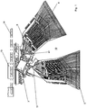
- FIG. 1 shows a plan view of an edging device according to the invention.
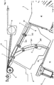
- FIG. 2 shows a cutout of the FIG. 1 in the area of the feeder.
- FIG. 1 illustrated edging device is part of a woodworking machine in which transported on a chain belt 14, plate-shaped workpieces 13, in particular made of wood or wood substitutes, spent to a pressure zone and be edged in this area with an edge strip on their narrow sides. This is done by adhesion by means of a gluing unit or - as in the example shown - by a laser assembly 8, with which the surface of the edge strip is melted by a laser beam 7, and then pressing against the narrow side of the workpiece 13 by means of a pressure roller 6 shown here ,
- a feed device 3 is provided, which is fed from an edge strip stocking device, which according to the invention has two magazines 4 and 5.
- the gap 10 between the magazines is chosen so that an operator finds in this place and the respective magazine 4, 5 can equip and reach at any point.
- the two magazines each have a transfer section 41 and 51, respectively, in which the edge strips 9 related to the magazine are transferred to the feed device 3.
- the feeder 3 is in the FIG. 2 shown in more detail.
- the edge strip selected from the respective magazine 4, 5 is unwound from the roll (not shown) and guided by the magazine into the transfer section 41, 51 and separated there by means of a separating knife 42, 52 from the rest of stock material and then taken over by the feeder 3.
- the feed device 3 has two feed paths 1 and 2, which lead from the transfer section 41 or 51 to the joining zone in the region of the pressure roller 6.
- the two paths 1, 2 combine to form a pressure roller 6 directed to the feed channel 12.
- a combination is not mandatory, even completely separate feed paths 1, 2 are conceivable.
- the feed paths 1, 2 each have - preferably on both sides - guide elements or guide segments 101, 201 in order to guide the edge strips cleanly in a predetermined direction. Furthermore, two feed rollers 102, 202 are also preferably provided on both sides of the paths 1, 2 in order to take over the edge strips from the magazines 4, 5 and to transport them to the joining zone.
- the two paths 1, 2 are angled towards each other or at least one of the paths (here 2) is curved.
- This allows a particularly advantageous because space-saving arrangement of the two magazines, which - as in FIG. 1 to see - with respect to the transport direction of the edge strips 9 in the region of the transfer sections 41, 51 are arranged at an angle to each other.
Landscapes
- Life Sciences & Earth Sciences (AREA)
- Engineering & Computer Science (AREA)
- Mechanical Engineering (AREA)
- Wood Science & Technology (AREA)
- Forests & Forestry (AREA)
- Delivering By Means Of Belts And Rollers (AREA)
Description
- Die Erfindung betrifft eine Bekantungsvorrichtung nach dem Oberbegriff des Anspruchs 1.
- Entsprechende Vorrichtungen sind aus
DE 10 2008 011 313 A1 oderEP 2 243 619 A1 bekannt. Üblicherweise werden eine Mehrzahl Kantenstreifen (oder auch Kantenbänder) vorgehalten, um verschiedene Möbelplatten mit Kantenstreifen unterschiedlicher Farbe, Dekoren oder Stärke zu bekanten. Damit dies maschinell funktioniert, wird eine Mehrzahl von Kantenstreifen in einer Kantenstreifenvorratseinrichtung vorgehalten, in welche die verschiedenen Rollen von Kantenstreifen händisch eingespannt werden müssen. - Wegen der Handhabbarkeit sind die Kapazitäten solcher Kantenstreifenvorratseinrichtungen begrenzt. Bei der kommissionsweisen Fertigung von Möbelteilen kann es vorkommen, dass die Kapazität der Kantenstreifenvorratseinrichtung für die benötigten Kantenstreifen nicht ausreicht. Es müssen dann von Hand Kantenstreifen in der Vorrichtung ausgetauscht werden, unerwünschte und vor Allem kostspielige Stillstandzeiten der Maschinen wären die Folge.
- Aus der
WO2008/003439 A1 ist eine Bekantungsvorrichtung offenbart, deren Kantenstreifenvorratseinrichtung ein erstes Kantenstreifenmagazin und ein hiervon beabstandetes zweites Kantenstreifenmagazin aufweist. - Der Erfindung liegt die Aufgabe zugrunde, eine Bekantungsvorrichtung der eingangs genannten Art anzugeben, mit der die Gefahr von Stillstandzeiten verringert ist und die eine größere Flexibilität bei der kommissionsweisen Fertigung von Möbelteilen bietet.
- Gelöst wird diese Aufgabe durch eine Bekantungsvorrichtung mit den Merkmalen des Anspruchs 1. Vorteilhafte Ausführungsformen finden sich in den Unteransprüchen.
- Erfindungsgemäß weist die Kantenstreifenvorratseinrichtung ein erstes Kantenstreifenmagazin und ein hiervon räumlich beabstandetes zweites Kantenstreifenmagazin auf. Dadurch kann die Kapazität des Systems verdoppelt werden und weniger händisches Nachlegen von Kantenrollen ist erforderlich, was die Stillstandzeiten minimiert.
- Insbesondere ist vorteilhafterweise vorgesehen, dass die räumliche Beabstandung zwischen den Kantenstreifenmagazinen so gewählt ist, dass eine Bedienperson zwischen den Kantenstreifenmagazinen Platz findet. So können Magazine maximaler Breite eingesetzt werden, insbesondere solche mit 48 verschiedenen Kantenstreifen. Zum Austauschen oder Neubestücken der Magazine ist zwischen den Magazinen genügend Platz, so dass eine Bedienperson jeden Bereich des Magazins erreichen kann.
- Erfindungsgemäß weisen die Kantenstreifenmagazine jeweils Übergabeabschnitte zur Übergabe eines ausgewählten Kantenstreifens an die Zuführeinrichtung auf. Die Zuführeinrichtung weist weiter für jedes Kantenstreifenmagazin einen Zuführweg auf, welcher jeweils vom Bereich des Übergabeabschnitts des zugehörigen Kantenstreifenmagazins zum Bereich der Andruckeinrichtung führen und/oder sich in Zuführrichtung betrachtet vor der Andruckeinrichtung zu einem Zuführkanal vereinigen. Dadurch können aus jedem Magazin Kantenstreifen gezogen und zum Werkstück geführt werden.
- Damit eine besonders platzsparende Anordnung der Magazine in der erfindungsgemäßen Vorrichtung möglich ist, kann insbesondere vorgesehen sein, dass einer der Zuführwege einen wenigstens abschnittweise gekrümmten Verlauf aufweist. Dadurch ist es möglich, die Magazine zueinander bezogen auf die Orientierung des Kantenstreifens im Bereich der Übergabe an die Zuführeinrichtung in einem Winkel anzuordnen.
- Zur Führung und Übernahme der aus dem Magazinen entnommenen und im Bereich der Übergabeabschnitte abgetrennten Kantenstreifen kann weiter vorgesehen sein, dass die Zuführwege Führungssegmente zur Führung der zugeführten Kantenstreifen und/oder Einzugrollen zum Transportieren der zugeführten Kantenstreifen aufweisen. Bevorzugt sind die Führungssegmente und die Einzugrollen beidseits der jeweiligen Zuführwege angeordnet.
- Die Erfindung wird nachfolgend anhand der
Figuren 1 und2 näher erläutert. -
Figur 1 zeigt eine Draufsicht auf eine erfindungsgemäße Bekantungsvorrichtung. -
Figur 2 zeigt eine Ausschnittvergrößerung derFigur 1 im Bereich der Zuführeinrichtung. - Die in
Figur 1 dargestellte Bekantungsvorrichtung ist Teil einer Holzbearbeitungsmaschine, bei der auf einem Kettenband 14 transportierte, plattenförmige Werkstücke 13, insbesondere aus Holz- oder Holzaustauschstoffen, zu einer Andruckzone verbracht und in diesem Bereich mit einem Kantenstreifen an ihren Schmalseiten bekantet werden. Dies geschieht durch Haftbarmachen mittels eines Verleimaggregats oder - wie im gezeigten Beispiel - durch ein Laseraggregat 8, mit dem die Oberfläche das Kantenstreifens durch einen Laserstrahl 7 aufgeschmolzen wird, und anschließendes Andrücken an die Schmalseite des Werkstücks 13 mit Hilfe einer hier als Andruckrolle 6 dargestellten Andruckeinrichtung. - Um den Kantenstreifen an das Werkstück 13 im Bereich der Andruckrolle 6 heranzuführen, ist eine Zuführeinrichtung 3 vorgesehen, die aus einer Kantenstreifenvorratseinrichtung gespeist wird, die erfindungsgemäß zwei Magazine 4 und 5 aufweist. Der Zwischenraum 10 zwischen den Magazinen ist so gewählt, dass eine Bedienperson in diesem Platz findet und das jeweilige Magazin 4, 5 bestücken und in jedem Punkt erreichen kann.
- Die beiden Magazine weisen jeweils einen Übergabeabschnitt 41 bzw. 51 auf, in denen die aus dem Magazin bezogenen Kantenstreifen 9 an die Zuführeinrichtung 3 übergeben werden. Die Zuführeinrichtung 3 ist in der
Figur 2 näher dargestellt. - Der aus dem jeweiligen Magazin 4, 5 ausgewählte Kantenstreifen wird von der Rolle (nicht gezeigt) abgewickelt und durch das Magazin in den Übergabeabschnitt 41, 51 geführt und dort mittels eines Trennmessers 42, 52 vom übrigen Vorratsmaterial abgetrennt und sodann von der Zuführeinrichtung 3 übernommen. Die Zuführeinrichtung 3 weist im gezeigten Beispiel zwei Zuführwege 1 und 2 auf, die vom Übergabeabschnitt 41 bzw. 51 zur Fügezone in den Bereich der Andruckrolle 6 führen. Die beiden Wege 1, 2 vereinigen sich zu einem zur Andruckrolle 6 gerichteten Zuführkanal 12. Eine Vereinigung ist nicht zwingend erforderlich, auch sind vollständig getrennte Zuführwege 1, 2 denkbar.
- Die Zuführwege 1, 2 weisen jeweils - bevorzugt zu beiden Seiten - Führungselemente bzw. Führungssegmente 101, 201 auf, um die Kantenstreifen sauber in eine vorgegebene Richtung zu lenken. Weiter sind ebenfalls bevorzugt beidseits der Wege 1, 2 Einzugrollen 102, 202 vorgesehen, um die Kantenstreifen aus den Magazinen 4, 5 zu übernehmen und zur Fügezone zu transportieren.
- Bevorzugt verlaufen die beiden Wege 1, 2 gewinkelt zu einander bzw. wenigstens einer der Wege (hier 2) ist gekrümmt. Dies ermöglicht eine besonders vorteilhafte weil platzsparende Anordnung der beiden Magazine, die - wie in
Figur 1 zu sehen - bezüglich der Transportrichtung der Kantenstreifen 9 im Bereich der Übergabeabschnitte 41, 51 zueinander gewinkelt angeordnet sind. Bevorzugt weisen die beiden (insbesondere baugleichen) Magazine 4, 5, zueinander im Bezug auf die Übergaberichtung der Kantenstreifen an die Zuführeinrichtung 3 eine 90°-Anordnung auf.
Claims (4)
- Bekantungsvorrichtung zum Bekanten der Schmalseite von plattenförmigen Werkstücken (13), mit einer Zuführeinrichtung (3) zum Zuführen von Kantenstreifen zu einem Werkstück (13), einer Andruckeinrichtung (6) zum Andrücken der Kantenstreifen (9) an die Schmalseite des Werkstücks (13), und einer Kantenstreifenvorratseinrichtung zum Vorhalten einer Mehrzahl Kantenstreifen (9), wobei die Zuführeinrichtung (3) mit der Kantenstreifenvorratseinrichtung so zusammenwirkt, dass sie jeweils mindestens einen vorgegebenen Kantenstreifen (9) aus der Kantenstreifenvorratseinrichtung entnimmt und dem Werkstück (13) zuführt,
dadurch gekennzeichnet,
dass die Kantenstreifenvorratseinrichtung ein erstes Kantenstreifenmagazin (4) zum Vorhalten einer Mehrzahl Kantenstreifen und ein hiervon räumlich beabstandetes zweites Kantenstreifenmagazin (5) zum Vorhalten einer Mehrzahl Kantenstreifen aufweist,
wobei die räumliche Beabstandung zwischen den Kantenstreifenmagazinen (4, 5) so gewählt ist, dass eine Bedienperson in dem Zwischenraum (10) zwischen den Kantenstreifenmagazinen (4, 5) Platz findet und das jeweilige Kantenstreifenmagazin (4, 5) in jedem Punkt erreichen kann, wobei weiter die Kantenstreifenmagazine (4, 5) jeweils Übergabeabschnitte (41, 52) zur Übergabe eines ausgewählten Kantenstreifens (9) an die Zuführeinrichtung (3) aufweisen und die Zuführeinrichtung (3) für jedes Kantenstreifenmagazin (4, 5) einen Zuführweg (1, 2) aufweist, welcher jeweils vom Bereich des Übergabeabschnitts (41, 51) des zugehörigen Kantenstreifenmagazins (4, 5) in den Bereich der Andruckeinrichtung (6) führen und/oder sich in Zuführrichtung betrachtet vor der Andruckeinrichtung (6) zu einem Zuführkanal (12) vereinigen, und wobei beiden Kantenstreifenmagazine (4, 5) bezüglich der Transportrichtung der Kantenstreifen (9) im Bereich der Übergabeabschnitte (41, 51) zueinander gewinkelt angeordnet sind. - Bekantungsvorrichtung nach Anspruch 1,
dadurch gekennzeichnet,
dass mindestens einer der Zuführwege (2) einen wenigstens abschnittweise gekrümmten Verlauf aufweist. - Bekantungsvorrichtung nach Anspruch 1 oder 2,
dadurch gekennzeichnet,
dass die Zuführwege (1, 2) Führungssegmente (101, 201) zur Führung der zugeführten Kantenstreifen (9) und/ oder Einzugrollen (201, 202) zum Transportieren der zugeführten Kantenstreifen (9) aufweisen. - Bekantungsvorrichtung nach einem der vorigen Ansprüche,
dadurch gekennzeichnet,
dass die Bekantungsvorrichtung eine Bekantungsvorrichtung zum Bekanten der Schmalseite von plattenförmigen Werkstücken (13) aus Holz- oder Holzaustauschstoffen ist.
Priority Applications (1)
| Application Number | Priority Date | Filing Date | Title |
|---|---|---|---|
| PL14000240T PL2762283T3 (pl) | 2013-02-02 | 2014-01-23 | Urządzenie do wykańczania krawędzi |
Applications Claiming Priority (1)
| Application Number | Priority Date | Filing Date | Title |
|---|---|---|---|
| DE102013001893.5A DE102013001893A1 (de) | 2013-02-02 | 2013-02-02 | Bekantungsvorrichtung |
Publications (2)
| Publication Number | Publication Date |
|---|---|
| EP2762283A1 EP2762283A1 (de) | 2014-08-06 |
| EP2762283B1 true EP2762283B1 (de) | 2019-05-08 |
Family
ID=50000767
Family Applications (1)
| Application Number | Title | Priority Date | Filing Date |
|---|---|---|---|
| EP14000240.3A Active EP2762283B1 (de) | 2013-02-02 | 2014-01-23 | Bekantungsvorrichtung |
Country Status (3)
| Country | Link |
|---|---|
| EP (1) | EP2762283B1 (de) |
| DE (1) | DE102013001893A1 (de) |
| PL (1) | PL2762283T3 (de) |
Families Citing this family (9)
| Publication number | Priority date | Publication date | Assignee | Title |
|---|---|---|---|---|
| DE102015206010A1 (de) * | 2015-04-02 | 2016-10-06 | Homag Holzbearbeitungssysteme Gmbh | Beschichtungsvorrichtung sowie Verfahren |
| DE102015213358A1 (de) * | 2015-07-16 | 2017-01-19 | Homag Holzbearbeitungssysteme Gmbh | Zuführeinrichtung für Beschichtungsmaterial |
| DE102016224488A1 (de) * | 2016-12-08 | 2018-06-14 | Homag Gmbh | Versorgungseinrichtung, Beschichtungsmaschine sowie Bevorratungsanordnung |
| FI129331B (fi) * | 2017-03-07 | 2021-12-15 | Lemtapes Oy | Menetelmä ja laite liima-aineen aktivoimiseksi |
| DE102017125936A1 (de) * | 2017-11-07 | 2019-05-09 | Ima Klessmann Gmbh Holzbearbeitungssysteme | Kantenverarbeitungsanlage |
| DE102017125937A1 (de) * | 2017-11-07 | 2019-05-09 | Ima Klessmann Gmbh Holzbearbeitungssysteme | Kantenbearbeitungsanordnung |
| DE102019120377A1 (de) | 2019-07-29 | 2021-02-04 | Ima Schelling Deutschland Gmbh | Vorrichtung, insbesondere Softforming-Vorrichtung, zum Anbringen von Kantenstreifen |
| DE102020105320A1 (de) * | 2020-02-28 | 2021-09-02 | Homag Gmbh | Zuführsystem für bandförmiges Material sowie Beschichtungsvorrichtung |
| DE102020116753A1 (de) | 2020-06-25 | 2021-12-30 | Homag Gmbh | Vorrichtung und Verfahren zum Beschichten eines Werkstücks |
Citations (4)
| Publication number | Priority date | Publication date | Assignee | Title |
|---|---|---|---|---|
| DE2722225A1 (de) * | 1977-05-17 | 1978-11-23 | Torwegge Maschf F | Kantenanleimmaschine |
| EP1977869A1 (de) * | 2007-04-04 | 2008-10-08 | Homag Holzbearbeitungssysteme AG | Versorgungsvorrichtung für Bearbeitungsmaschinen |
| EP2243619A1 (de) * | 2009-04-22 | 2010-10-27 | Homag Holzbearbeitungssysteme AG | Vorrichtung und Verfahren zum Beschichten von Werkstücken |
| EP2505322A1 (de) * | 2011-03-29 | 2012-10-03 | Homag Holzbearbeitungssysteme AG | Maschinensystem |
Family Cites Families (4)
| Publication number | Priority date | Publication date | Assignee | Title |
|---|---|---|---|---|
| DE7031331U (de) * | 1970-08-21 | 1971-09-02 | Klessmann Ima Norte Maschfab | Trommelmagazin fuer furnierkanten-maschine. |
| DE2722414C3 (de) * | 1977-05-17 | 1983-11-10 | Hornberger Maschinenbaugesellschaft mbH & Co KG, 7294 Schopfloch | Vorrichtung zum Zuführen von Band- oder Streifenmaterial bei einer Kantenanleimmaschine |
| DE102006030624A1 (de) * | 2006-07-04 | 2008-01-17 | Rehau Ag + Co | Verfahren zum Herstellen und Montieren einer bedruckten Kantenleiste |
| DE102008011313A1 (de) | 2008-02-27 | 2009-09-03 | Ima Klessmann Gmbh Holzbearbeitungssysteme | Einrichtung zum Zuführen von Kantenstreifen |
-
2013
- 2013-02-02 DE DE102013001893.5A patent/DE102013001893A1/de not_active Withdrawn
-
2014
- 2014-01-23 EP EP14000240.3A patent/EP2762283B1/de active Active
- 2014-01-23 PL PL14000240T patent/PL2762283T3/pl unknown
Patent Citations (4)
| Publication number | Priority date | Publication date | Assignee | Title |
|---|---|---|---|---|
| DE2722225A1 (de) * | 1977-05-17 | 1978-11-23 | Torwegge Maschf F | Kantenanleimmaschine |
| EP1977869A1 (de) * | 2007-04-04 | 2008-10-08 | Homag Holzbearbeitungssysteme AG | Versorgungsvorrichtung für Bearbeitungsmaschinen |
| EP2243619A1 (de) * | 2009-04-22 | 2010-10-27 | Homag Holzbearbeitungssysteme AG | Vorrichtung und Verfahren zum Beschichten von Werkstücken |
| EP2505322A1 (de) * | 2011-03-29 | 2012-10-03 | Homag Holzbearbeitungssysteme AG | Maschinensystem |
Also Published As
| Publication number | Publication date |
|---|---|
| PL2762283T3 (pl) | 2019-10-31 |
| EP2762283A1 (de) | 2014-08-06 |
| DE102013001893A1 (de) | 2014-08-07 |
Similar Documents
| Publication | Publication Date | Title |
|---|---|---|
| EP2762283A1 (de) | Bekantungsvorrichtung | |
| EP2684683A1 (de) | Vorrichtung zum Nuten von Pappenzuschnitten | |
| DE102013008595A1 (de) | Maschine zur Umleimung von Platten aus Holz oder Ähnlichem | |
| WO2016087208A1 (de) | Plattenaufteilanlage zum aufteilen von plattenförmigen werkstücken, sowie verfahren zu deren betrieb | |
| EP2505322B1 (de) | Maschinensystem | |
| DE102010024232A1 (de) | Verfahren und Vorrichtung zur Herstellung von Buchdecken | |
| EP2095921B1 (de) | Einrichtung zum Zuführen von Kantenstreifen | |
| DE3515729A1 (de) | Platteneinschiebevorrichtung zum einschieben von auf einem hubtisch abgelegten plattenfoermigen werkstuecken in plattenaufteilanlagen | |
| EP3492231B1 (de) | Kantenbearbeitungsanordnung | |
| DE102014008016B4 (de) | Verfahren zur Ausrichtung plattenförmiger Werkstücke auf einer Fördereinrichtung einer Bearbeitungsmaschine und Bearbeitungsmaschine | |
| DE102016225587A1 (de) | Verfahren zum Ausrichten eines Werkstücks sowie Ausrichtvorrichtung | |
| AT518387B1 (de) | Verfahren und Vorrichtung zum Herstellen von Lamellenlagen aus hintereinander aufgereihten Lamellen | |
| EP3037227B1 (de) | Verfahren und vorrichtung zur bearbeitung von plattenförmigen werkstücken | |
| EP0175795B1 (de) | Kaschierstation | |
| EP0489681B1 (de) | Verfahren zum Verschieben kantenbündig aufeinandergestapelter streifen- oder plattenförmiger Werkstücke auf einer reibungsarmen Werkstückauflage, sowie Vorrichtung zur Durchführung dieses Verfahrens | |
| EP2949439B1 (de) | Bearbeitungsvorrichtung und bearbeitungsverfahren | |
| EP4110617B1 (de) | Vorrichtung und verfahren zum ablegen von furnieren | |
| WO2009062653A1 (de) | Beschickungsvorrichtung für furnierzusammensetzmaschinen | |
| EP0819641A1 (de) | Einrichtung zum Verarbeiten von gefalzten Druckbogen | |
| DE102014113048A1 (de) | Verfahren zum Herstellen einer Mittellage von Parkettbodenelementen, Mittellage und Vorrichtung zur Durchführung des Verfahrens | |
| EP3702157B1 (de) | Verfahren und vorrichtung zum exakten legen von bögen | |
| EP2113374B1 (de) | Faltschachtelklebemaschine zur Herstellung von Faltschachteln aus Zuschnitten | |
| EP2388149B1 (de) | Vorrichtung zum Ablängen und Zuführen von Rückeneinlagen für eine Buchdeckenmaschine | |
| CH693329A5 (de) | Vorrichtung zum Auftrageneines Klebstoffstreifens auf einen gefalztenVorsatzbogen. | |
| DE19712698C2 (de) | Anlage zum ausgerichteten Zuführen von Füllstreifen aus Dämmaterial im Zuge der Fertigung von Sandwichelementen |
Legal Events
| Date | Code | Title | Description |
|---|---|---|---|
| PUAI | Public reference made under article 153(3) epc to a published international application that has entered the european phase |
Free format text: ORIGINAL CODE: 0009012 |
|
| 17P | Request for examination filed |
Effective date: 20140123 |
|
| AK | Designated contracting states |
Kind code of ref document: A1 Designated state(s): AL AT BE BG CH CY CZ DE DK EE ES FI FR GB GR HR HU IE IS IT LI LT LU LV MC MK MT NL NO PL PT RO RS SE SI SK SM TR |
|
| AX | Request for extension of the european patent |
Extension state: BA ME |
|
| R17P | Request for examination filed (corrected) |
Effective date: 20150121 |
|
| RBV | Designated contracting states (corrected) |
Designated state(s): AL AT BE BG CH CY CZ DE DK EE ES FI FR GB GR HR HU IE IS IT LI LT LU LV MC MK MT NL NO PL PT RO RS SE SI SK SM TR |
|
| 17Q | First examination report despatched |
Effective date: 20151211 |
|
| STAA | Information on the status of an ep patent application or granted ep patent |
Free format text: STATUS: EXAMINATION IS IN PROGRESS |
|
| GRAP | Despatch of communication of intention to grant a patent |
Free format text: ORIGINAL CODE: EPIDOSNIGR1 |
|
| STAA | Information on the status of an ep patent application or granted ep patent |
Free format text: STATUS: GRANT OF PATENT IS INTENDED |
|
| INTG | Intention to grant announced |
Effective date: 20190130 |
|
| GRAS | Grant fee paid |
Free format text: ORIGINAL CODE: EPIDOSNIGR3 |
|
| GRAJ | Information related to disapproval of communication of intention to grant by the applicant or resumption of examination proceedings by the epo deleted |
Free format text: ORIGINAL CODE: EPIDOSDIGR1 |
|
| GRAL | Information related to payment of fee for publishing/printing deleted |
Free format text: ORIGINAL CODE: EPIDOSDIGR3 |
|
| STAA | Information on the status of an ep patent application or granted ep patent |
Free format text: STATUS: EXAMINATION IS IN PROGRESS |
|
| GRAP | Despatch of communication of intention to grant a patent |
Free format text: ORIGINAL CODE: EPIDOSNIGR1 |
|
| STAA | Information on the status of an ep patent application or granted ep patent |
Free format text: STATUS: GRANT OF PATENT IS INTENDED |
|
| GRAA | (expected) grant |
Free format text: ORIGINAL CODE: 0009210 |
|
| STAA | Information on the status of an ep patent application or granted ep patent |
Free format text: STATUS: THE PATENT HAS BEEN GRANTED |
|
| INTC | Intention to grant announced (deleted) | ||
| INTG | Intention to grant announced |
Effective date: 20190329 |
|
| AK | Designated contracting states |
Kind code of ref document: B1 Designated state(s): AL AT BE BG CH CY CZ DE DK EE ES FI FR GB GR HR HU IE IS IT LI LT LU LV MC MK MT NL NO PL PT RO RS SE SI SK SM TR |
|
| REG | Reference to a national code |
Ref country code: GB Ref legal event code: FG4D Free format text: NOT ENGLISH |
|
| REG | Reference to a national code |
Ref country code: CH Ref legal event code: EP Ref country code: AT Ref legal event code: REF Ref document number: 1129473 Country of ref document: AT Kind code of ref document: T Effective date: 20190515 |
|
| REG | Reference to a national code |
Ref country code: DE Ref legal event code: R096 Ref document number: 502014011625 Country of ref document: DE Ref country code: IE Ref legal event code: FG4D Free format text: LANGUAGE OF EP DOCUMENT: GERMAN |
|
| REG | Reference to a national code |
Ref country code: NL Ref legal event code: MP Effective date: 20190508 |
|
| REG | Reference to a national code |
Ref country code: LT Ref legal event code: MG4D |
|
| PG25 | Lapsed in a contracting state [announced via postgrant information from national office to epo] |
Ref country code: LT Free format text: LAPSE BECAUSE OF FAILURE TO SUBMIT A TRANSLATION OF THE DESCRIPTION OR TO PAY THE FEE WITHIN THE PRESCRIBED TIME-LIMIT Effective date: 20190508 Ref country code: HR Free format text: LAPSE BECAUSE OF FAILURE TO SUBMIT A TRANSLATION OF THE DESCRIPTION OR TO PAY THE FEE WITHIN THE PRESCRIBED TIME-LIMIT Effective date: 20190508 Ref country code: SE Free format text: LAPSE BECAUSE OF FAILURE TO SUBMIT A TRANSLATION OF THE DESCRIPTION OR TO PAY THE FEE WITHIN THE PRESCRIBED TIME-LIMIT Effective date: 20190508 Ref country code: FI Free format text: LAPSE BECAUSE OF FAILURE TO SUBMIT A TRANSLATION OF THE DESCRIPTION OR TO PAY THE FEE WITHIN THE PRESCRIBED TIME-LIMIT Effective date: 20190508 Ref country code: NO Free format text: LAPSE BECAUSE OF FAILURE TO SUBMIT A TRANSLATION OF THE DESCRIPTION OR TO PAY THE FEE WITHIN THE PRESCRIBED TIME-LIMIT Effective date: 20190808 Ref country code: PT Free format text: LAPSE BECAUSE OF FAILURE TO SUBMIT A TRANSLATION OF THE DESCRIPTION OR TO PAY THE FEE WITHIN THE PRESCRIBED TIME-LIMIT Effective date: 20190908 Ref country code: AL Free format text: LAPSE BECAUSE OF FAILURE TO SUBMIT A TRANSLATION OF THE DESCRIPTION OR TO PAY THE FEE WITHIN THE PRESCRIBED TIME-LIMIT Effective date: 20190508 Ref country code: ES Free format text: LAPSE BECAUSE OF FAILURE TO SUBMIT A TRANSLATION OF THE DESCRIPTION OR TO PAY THE FEE WITHIN THE PRESCRIBED TIME-LIMIT Effective date: 20190508 Ref country code: NL Free format text: LAPSE BECAUSE OF FAILURE TO SUBMIT A TRANSLATION OF THE DESCRIPTION OR TO PAY THE FEE WITHIN THE PRESCRIBED TIME-LIMIT Effective date: 20190508 |
|
| PG25 | Lapsed in a contracting state [announced via postgrant information from national office to epo] |
Ref country code: BG Free format text: LAPSE BECAUSE OF FAILURE TO SUBMIT A TRANSLATION OF THE DESCRIPTION OR TO PAY THE FEE WITHIN THE PRESCRIBED TIME-LIMIT Effective date: 20190808 Ref country code: LV Free format text: LAPSE BECAUSE OF FAILURE TO SUBMIT A TRANSLATION OF THE DESCRIPTION OR TO PAY THE FEE WITHIN THE PRESCRIBED TIME-LIMIT Effective date: 20190508 Ref country code: RS Free format text: LAPSE BECAUSE OF FAILURE TO SUBMIT A TRANSLATION OF THE DESCRIPTION OR TO PAY THE FEE WITHIN THE PRESCRIBED TIME-LIMIT Effective date: 20190508 Ref country code: GR Free format text: LAPSE BECAUSE OF FAILURE TO SUBMIT A TRANSLATION OF THE DESCRIPTION OR TO PAY THE FEE WITHIN THE PRESCRIBED TIME-LIMIT Effective date: 20190809 |
|
| REG | Reference to a national code |
Ref country code: DE Ref legal event code: R082 Ref document number: 502014011625 Country of ref document: DE Representative=s name: THIELKING & ELBERTZHAGEN PATENTANWAELTE, DE Ref country code: DE Ref legal event code: R081 Ref document number: 502014011625 Country of ref document: DE Owner name: IMA SCHELLING DEUTSCHLAND GMBH, DE Free format text: FORMER OWNER: IMA KLESSMANN GMBH HOLZBEARBEITUNGSSYSTEME, 32312 LUEBBECKE, DE |
|
| PG25 | Lapsed in a contracting state [announced via postgrant information from national office to epo] |
Ref country code: RO Free format text: LAPSE BECAUSE OF FAILURE TO SUBMIT A TRANSLATION OF THE DESCRIPTION OR TO PAY THE FEE WITHIN THE PRESCRIBED TIME-LIMIT Effective date: 20190508 Ref country code: SK Free format text: LAPSE BECAUSE OF FAILURE TO SUBMIT A TRANSLATION OF THE DESCRIPTION OR TO PAY THE FEE WITHIN THE PRESCRIBED TIME-LIMIT Effective date: 20190508 Ref country code: DK Free format text: LAPSE BECAUSE OF FAILURE TO SUBMIT A TRANSLATION OF THE DESCRIPTION OR TO PAY THE FEE WITHIN THE PRESCRIBED TIME-LIMIT Effective date: 20190508 Ref country code: EE Free format text: LAPSE BECAUSE OF FAILURE TO SUBMIT A TRANSLATION OF THE DESCRIPTION OR TO PAY THE FEE WITHIN THE PRESCRIBED TIME-LIMIT Effective date: 20190508 Ref country code: CZ Free format text: LAPSE BECAUSE OF FAILURE TO SUBMIT A TRANSLATION OF THE DESCRIPTION OR TO PAY THE FEE WITHIN THE PRESCRIBED TIME-LIMIT Effective date: 20190508 |
|
| REG | Reference to a national code |
Ref country code: DE Ref legal event code: R097 Ref document number: 502014011625 Country of ref document: DE |
|
| PG25 | Lapsed in a contracting state [announced via postgrant information from national office to epo] |
Ref country code: SM Free format text: LAPSE BECAUSE OF FAILURE TO SUBMIT A TRANSLATION OF THE DESCRIPTION OR TO PAY THE FEE WITHIN THE PRESCRIBED TIME-LIMIT Effective date: 20190508 |
|
| PLBE | No opposition filed within time limit |
Free format text: ORIGINAL CODE: 0009261 |
|
| STAA | Information on the status of an ep patent application or granted ep patent |
Free format text: STATUS: NO OPPOSITION FILED WITHIN TIME LIMIT |
|
| PG25 | Lapsed in a contracting state [announced via postgrant information from national office to epo] |
Ref country code: TR Free format text: LAPSE BECAUSE OF FAILURE TO SUBMIT A TRANSLATION OF THE DESCRIPTION OR TO PAY THE FEE WITHIN THE PRESCRIBED TIME-LIMIT Effective date: 20190508 |
|
| 26N | No opposition filed |
Effective date: 20200211 |
|
| PG25 | Lapsed in a contracting state [announced via postgrant information from national office to epo] |
Ref country code: SI Free format text: LAPSE BECAUSE OF FAILURE TO SUBMIT A TRANSLATION OF THE DESCRIPTION OR TO PAY THE FEE WITHIN THE PRESCRIBED TIME-LIMIT Effective date: 20190508 |
|
| PG25 | Lapsed in a contracting state [announced via postgrant information from national office to epo] |
Ref country code: MC Free format text: LAPSE BECAUSE OF FAILURE TO SUBMIT A TRANSLATION OF THE DESCRIPTION OR TO PAY THE FEE WITHIN THE PRESCRIBED TIME-LIMIT Effective date: 20190508 |
|
| REG | Reference to a national code |
Ref country code: CH Ref legal event code: PL |
|
| GBPC | Gb: european patent ceased through non-payment of renewal fee |
Effective date: 20200123 |
|
| REG | Reference to a national code |
Ref country code: BE Ref legal event code: MM Effective date: 20200131 |
|
| PG25 | Lapsed in a contracting state [announced via postgrant information from national office to epo] |
Ref country code: LU Free format text: LAPSE BECAUSE OF NON-PAYMENT OF DUE FEES Effective date: 20200123 Ref country code: GB Free format text: LAPSE BECAUSE OF NON-PAYMENT OF DUE FEES Effective date: 20200123 |
|
| PG25 | Lapsed in a contracting state [announced via postgrant information from national office to epo] |
Ref country code: CH Free format text: LAPSE BECAUSE OF NON-PAYMENT OF DUE FEES Effective date: 20200131 Ref country code: BE Free format text: LAPSE BECAUSE OF NON-PAYMENT OF DUE FEES Effective date: 20200131 Ref country code: LI Free format text: LAPSE BECAUSE OF NON-PAYMENT OF DUE FEES Effective date: 20200131 |
|
| PG25 | Lapsed in a contracting state [announced via postgrant information from national office to epo] |
Ref country code: IE Free format text: LAPSE BECAUSE OF NON-PAYMENT OF DUE FEES Effective date: 20200123 |
|
| REG | Reference to a national code |
Ref country code: AT Ref legal event code: MM01 Ref document number: 1129473 Country of ref document: AT Kind code of ref document: T Effective date: 20200123 |
|
| PG25 | Lapsed in a contracting state [announced via postgrant information from national office to epo] |
Ref country code: AT Free format text: LAPSE BECAUSE OF NON-PAYMENT OF DUE FEES Effective date: 20200123 |
|
| PG25 | Lapsed in a contracting state [announced via postgrant information from national office to epo] |
Ref country code: MT Free format text: LAPSE BECAUSE OF FAILURE TO SUBMIT A TRANSLATION OF THE DESCRIPTION OR TO PAY THE FEE WITHIN THE PRESCRIBED TIME-LIMIT Effective date: 20190508 Ref country code: CY Free format text: LAPSE BECAUSE OF FAILURE TO SUBMIT A TRANSLATION OF THE DESCRIPTION OR TO PAY THE FEE WITHIN THE PRESCRIBED TIME-LIMIT Effective date: 20190508 |
|
| PG25 | Lapsed in a contracting state [announced via postgrant information from national office to epo] |
Ref country code: MK Free format text: LAPSE BECAUSE OF FAILURE TO SUBMIT A TRANSLATION OF THE DESCRIPTION OR TO PAY THE FEE WITHIN THE PRESCRIBED TIME-LIMIT Effective date: 20190508 Ref country code: IS Free format text: LAPSE BECAUSE OF FAILURE TO SUBMIT A TRANSLATION OF THE DESCRIPTION OR TO PAY THE FEE WITHIN THE PRESCRIBED TIME-LIMIT Effective date: 20190908 |
|
| P01 | Opt-out of the competence of the unified patent court (upc) registered |
Effective date: 20230522 |
|
| PGFP | Annual fee paid to national office [announced via postgrant information from national office to epo] |
Ref country code: FR Payment date: 20250123 Year of fee payment: 12 |
|
| PGFP | Annual fee paid to national office [announced via postgrant information from national office to epo] |
Ref country code: DE Payment date: 20260304 Year of fee payment: 13 |
|
| PGFP | Annual fee paid to national office [announced via postgrant information from national office to epo] |
Ref country code: IT Payment date: 20260126 Year of fee payment: 13 |
|
| PGFP | Annual fee paid to national office [announced via postgrant information from national office to epo] |
Ref country code: PL Payment date: 20260112 Year of fee payment: 13 |