EP2762241B1 - Hot slab shape control equipment and shape control method - Google Patents
Hot slab shape control equipment and shape control method Download PDFInfo
- Publication number
- EP2762241B1 EP2762241B1 EP12843671.4A EP12843671A EP2762241B1 EP 2762241 B1 EP2762241 B1 EP 2762241B1 EP 12843671 A EP12843671 A EP 12843671A EP 2762241 B1 EP2762241 B1 EP 2762241B1
- Authority
- EP
- European Patent Office
- Prior art keywords
- slab
- width
- rolling mill
- shape control
- horizontal rolling
- Prior art date
- Legal status (The legal status is an assumption and is not a legal conclusion. Google has not performed a legal analysis and makes no representation as to the accuracy of the status listed.)
- Not-in-force
Links
- 238000000034 method Methods 0.000 title claims description 33
- 238000005096 rolling process Methods 0.000 claims description 134
- 230000009467 reduction Effects 0.000 claims description 55
- 238000003825 pressing Methods 0.000 claims description 40
- 230000001603 reducing effect Effects 0.000 claims description 17
- 238000010438 heat treatment Methods 0.000 claims description 11
- 238000011144 upstream manufacturing Methods 0.000 claims description 8
- 238000000605 extraction Methods 0.000 claims description 5
- 238000004513 sizing Methods 0.000 description 19
- 230000000052 comparative effect Effects 0.000 description 18
- 241000251468 Actinopterygii Species 0.000 description 14
- 238000007688 edging Methods 0.000 description 12
- 230000000669 biting effect Effects 0.000 description 9
- 230000000694 effects Effects 0.000 description 9
- 230000008859 change Effects 0.000 description 7
- 230000007935 neutral effect Effects 0.000 description 7
- 230000006872 improvement Effects 0.000 description 6
- 238000009749 continuous casting Methods 0.000 description 5
- 238000007796 conventional method Methods 0.000 description 4
- 238000009826 distribution Methods 0.000 description 4
- 239000000463 material Substances 0.000 description 4
- 238000012986 modification Methods 0.000 description 4
- 230000004048 modification Effects 0.000 description 4
- 230000008569 process Effects 0.000 description 4
- 238000005098 hot rolling Methods 0.000 description 3
- 230000007246 mechanism Effects 0.000 description 3
- 238000004458 analytical method Methods 0.000 description 2
- 238000005266 casting Methods 0.000 description 2
- 239000002184 metal Substances 0.000 description 2
- 238000012545 processing Methods 0.000 description 2
- 229910000831 Steel Inorganic materials 0.000 description 1
- 238000004364 calculation method Methods 0.000 description 1
- 230000015556 catabolic process Effects 0.000 description 1
- 239000012141 concentrate Substances 0.000 description 1
- 238000012937 correction Methods 0.000 description 1
- 238000005520 cutting process Methods 0.000 description 1
- 230000003247 decreasing effect Effects 0.000 description 1
- 230000002950 deficient Effects 0.000 description 1
- 238000006731 degradation reaction Methods 0.000 description 1
- 230000006866 deterioration Effects 0.000 description 1
- 230000002542 deteriorative effect Effects 0.000 description 1
- 238000009434 installation Methods 0.000 description 1
- 238000004519 manufacturing process Methods 0.000 description 1
- 230000003449 preventive effect Effects 0.000 description 1
- 238000011160 research Methods 0.000 description 1
- 230000000452 restraining effect Effects 0.000 description 1
- 239000010959 steel Substances 0.000 description 1
- 230000008961 swelling Effects 0.000 description 1
- 238000012546 transfer Methods 0.000 description 1
Images


Classifications
-
- B—PERFORMING OPERATIONS; TRANSPORTING
- B21—MECHANICAL METAL-WORKING WITHOUT ESSENTIALLY REMOVING MATERIAL; PUNCHING METAL
- B21J—FORGING; HAMMERING; PRESSING METAL; RIVETING; FORGE FURNACES
- B21J1/00—Preparing metal stock or similar ancillary operations prior, during or post forging, e.g. heating or cooling
- B21J1/02—Preliminary treatment of metal stock without particular shaping, e.g. salvaging segregated zones, forging or pressing in the rough
-
- B—PERFORMING OPERATIONS; TRANSPORTING
- B21—MECHANICAL METAL-WORKING WITHOUT ESSENTIALLY REMOVING MATERIAL; PUNCHING METAL
- B21B—ROLLING OF METAL
- B21B1/00—Metal-rolling methods or mills for making semi-finished products of solid or profiled cross-section; Sequence of operations in milling trains; Layout of rolling-mill plant, e.g. grouping of stands; Succession of passes or of sectional pass alternations
- B21B1/02—Metal-rolling methods or mills for making semi-finished products of solid or profiled cross-section; Sequence of operations in milling trains; Layout of rolling-mill plant, e.g. grouping of stands; Succession of passes or of sectional pass alternations for rolling heavy work, e.g. ingots, slabs, blooms, or billets, in which the cross-sectional form is unimportant ; Rolling combined with forging or pressing
- B21B1/026—Rolling
-
- B—PERFORMING OPERATIONS; TRANSPORTING
- B21—MECHANICAL METAL-WORKING WITHOUT ESSENTIALLY REMOVING MATERIAL; PUNCHING METAL
- B21B—ROLLING OF METAL
- B21B15/00—Arrangements for performing additional metal-working operations specially combined with or arranged in, or specially adapted for use in connection with, metal-rolling mills
- B21B15/0035—Forging or pressing devices as units
Definitions
- the present invention relates to shape control equipment and a shape control method for a hot slab. Specifically, the present invention relates to a shape control equipment and a shape control method for a hot slab that control a plain view pattern of top and tail ends of slab when a thickness and a width of a slab produced by continuous casting are shaped so as to reduce crop loss and that reduce a local thickness increase at the width center of the top end of the slab so as to solve a problem of reducing pass number of rough rolling and conveying trouble.
- the casting speed of a slab casted by a continuous casting machine hardly depends on the slab width. Therefore, in order to improve productivity, a method for casting a slab with a large width and reducing the width of the slab to a predetermined slab width corresponding to the product width in a hot-rolling line.
- a sizing mill and a sizing press have been developed and are used.
- This sizing mill is a device that performs slab-width rolling with rolling rolls mutually opposed on both sides in a slab width direction. However, the contact length of the rolls and the slab is short. Therefore, shear deformation to end portions of the slab width is large.
- the sizing press has been developed so as to achieve significant improvement in the yield.
- width reducing load is approximately proportional to the contact length between the slab and the mold. Accordingly, from the aspect of load limitation of the equipment, the width is changed up to about 300 mm.
- the width of a typical hot-rolled steel strip product varies from about 700 mm to 2200 mm. Even in the case where the sizing press device is utilized in the hot-rolling line, it is necessary to cast slabs with widths at a plurality of levels by other chances in the continuous casting process.
- the following two problems occur in the sizing press processing.
- One of the problems is a problem A that heavy width reduction increases the slab-top-end width and increases the pass number of rough rolling after the width press, thus reducing production efficiency.
- Another problem is a problem B that a slab non-constant portion (both end portions in the longitudinal direction) cannot be formed to have a plain view pattern in a rectangular shape and crop loss increases after rough rolling as illustrated in FIG. 14 , thus deteriorating yield.
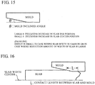
- a known method A increases a mold inclined angle ⁇ illustrated in FIG. 15 and controls the increased thickness position in the slab thickness direction so as to prevent the thickness increase (see Patent Literature 1).
- a known method B illustrated in FIG 16 adjusts a contact length L between the slab and the mold so as to adjust the shapes of the top and tail ends (see Patent Literature 2).
- Patent Literature 3 As a method for expanding the amount of the width change of the continuous-casting slab while reducing the concave shape referred to as a fish tail, which causes deterioration in yield, in the top and tail ends without increasing the load on the equipment, a method that is a combination of the sizing mill and the sizing press has been proposed (see Patent Literature 3). This is a method for changing the width of a constant portion by the sizing mill after preforming the top and tail ends of slab by the sizing press in advance so as to prevent the fish tail. This achieves a large width change of about 650 mm. When preforming by the sizing press significantly changes the width, the thickness of the top end of the slab increases and the slab collides with the roll for conveyance. This makes the conveyance difficult. Accordingly, a device that is devised to mechanically correct the top end of the slab by a lower roll, which is disposed on a conveyor line and can apply upward load, and this device is operated (see Patent Literature 4).
- JP S55 5103 A discloses an edging method for a slab wherein, when the breadth of the slab is to be greatly reduced by the hot rolling pass, the side press machine consisting of well-known couple of anvils are employed.
- the employed couple of anvils is provided with a taper groove which makes the sectional shape of the slab after the edging pass to be a flat octagonal section that is provided with a chamfering grade.
- the edging pass is executed while continuing an adjustment for obtaining the necessary breadth of the slab; hereupon, the edging pass is executed while restraining the slab by a bucking preventive pusher plate for the upper portion, and by the horizontal roll for the lower portion, in the same vertical plane as the couple of anvils.
- the edging pass can be executed at a large draft percentage, and also, the increase of breadth at the next horizontal roll is prevented, so that the product of various breadths can be rolled from the slab of single breadth size.
- the preamble of claim 1 is based on the document JP S55 5103 . In JP H01 284401A a method for edge pressing and a device therefor are described.
- edging of a slab transferred from the upstream side is performed by a rolling mill installed in the inlet side of a press housing before edging by press metal dies. Only the central part of the slab in the cross direction is rolled to have a recessed shape because both ends of upper and lower horizontal rolling rolls of the mill are tapered.
- a draft cylinder extends to push the facing dies through metal die holders onto the edge surfaces of the slab and to perform a prescribed edging.
- a deformation elongation by drafting is concentrated in the central part in the cross direction of the slab and the central part is bulged to form the sectional shape into a near rectangular shape. Therefore, strong edging of a comparatively narrow slab can be performed.
- JP H07 275901 A a method fo continuously edging a hot slab is described.
- devices for clamping a slab and imparting tensile stress in the advancing direction to the slab are provided before and behind a press device for edging the hot slab.
- a range of the tensile stress is set to a particular interval.
- the conventional method A has a small effect on reduction in increase of the slab-top-end width. This does not lead to significant improvement in efficiency. Since the angle of the mold is constant, a sufficient effect cannot be obtained depending on the slab width. Since the mold length in the conventional method B is limited, the effect has a limitation. The reduction effect in thickness increase is not specifically mentioned, and the effect is considered to be poor.
- Patent Literature 3 the amount of the width change per one pass is small in a vertical rolling mill. In order to increase the width change of the slab, a high rolling pass number is required. Therefore, productivity becomes poor and the slab temperature is reduced. Furthermore, for heavy width reduction in the top end of the slab by the sizing press, a considerable thickness increase occurs in the top end portion. Accordingly, introduction of the correction device as described in Patent Literature 4 becomes a precondition. Thus, there are problems in many points such as installation space, equipment cost, and running cost.
- the present invention keeps a small fish-tail shape in the top and tail ends due to a width change of the slab during sizing press process and prevents conveying trouble, defective biting during horizontal rolling of the slab after the width change by the rough rolling mill in the downstream side, and a local thickness increase in the width center of the top end of the slab causing an increase in pass number. Additionally, the present invention can significantly change the width while maintaining excellent shapes at the top and tail ends. Thus, improvement in yield and improvement in efficiency of the continuous casting machine can be expected.
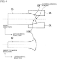
- a width reducing load P is decomposed into a mold inclined angle ⁇ so as to generate a force Psin ⁇ that moves the slab backward as illustrated in FIG. 3 .
- a friction force ⁇ P acts in the contact area between the mold 2K and a slab 10.
- the horizontal component force uPcos ⁇ blocks the backward movement of the slab 10.
- FIG. 4 illustrates a mechanism of a thickness increase of the slab width center 10WC after the top end of the slab becomes to have a fish-tail shape and illustrates the appearance of a longitudinal thickness distribution of the slab width center 10WC after the thickness increase.
- FIG. 1A and FIG. 1B are respectively a side view and a plan view illustrating the outline of the shape control equipment for the hot slab according to the present invention described in the above-described (1).
- a horizontal rolling mill 1 includes horizontal rolling rolls 1 HR mutually opposed on both sides in the slab thickness direction.
- a width pressing machine 2 includes a pair of molds (width press molds) 2K mutually opposed on both sides in the slab width direction.
- the horizontal rolling mill 1 and the width pressing machine 2 are installed in this order from the upstream side of the slab conveying direction at an arrangement interval ⁇ shorter than the slab length during extraction from heating furnace. That is, the slab length during extraction from heating furnace is expressed with L0 as 0 ⁇ ⁇ ⁇ L0, preferably, 0 ⁇ ⁇ ⁇ 0.3 ⁇ L0.
- slab thickness rolling by the horizontal rolling mill 1 and reduction of the width of a slab by the width pressing machine 2 are simultaneously performed on one hot slab.
- This allows applying a compressive force against the above-described backward component force Psin ⁇ to the slab by transfer using the horizontal rolling rolls 1HR of the horizontal rolling mill 1 at the upstream side of the mold 2K during reduction of the width of a slab by the molds 2K of the width pressing machine 2, thus controlling the top-end shape.
- This method reduces fish tail in the top end portion independently of the slab width or the reduction amount of the width of a slab and allows heavy width reduction while reducing a local thickness increase caused by the fish tail portion in the slab width center.
- the horizontal rolling mill 1 is preferred to perform rolling speed control such that a rolling slip does not occur and the compressive force acts on the slab at the exit side of the horizontal rolling mill.
- the occurrence condition of a slip during rolling can be determined based on whether or not the neutral point (in flat rolling) exists in a roll bite.
- FIG. 5 illustrates the result of performing rolling analysis assuming that the horizontal rolling mill applies load of a compressive force.
- the horizontal width of a slab equivalent to have a thickness of 260 mm and a temperature of 1000°C was reduced to have a thickness of 245 mm in a roll with ⁇ 1000 mm.
- From the downstream of the horizontal rolling mill applying load of a pushing force moves the neutral point (in flat rolling) to the exit side of the roll bite.
- a pushing force of about 11 MPa or less did not cause a slip.
- this pushing force that is, compressive force, a shape control of the slab-top-end portion was performed.
- the present invention was applied to the case where a slab with a width of 1450 mm and a slab thickness of 260 mm was set as a target and reduction of the width of a slab by 325 mm for each reduction was performed twice so as to reduce 650 mm in the total reduction amount of the width of a slab.
- the reduction of the width of a slab was started from a mold inclined portion. Only at the time of the first pass, a compressive force of 9 MPa against the backward component force was applied by the horizontal rolling mill.
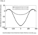
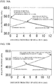
- FIG. 6 illustrates a top-end plain view pattern after the reduction of the width of a slab. Ordinary reduction of the width of a slab (with a compressive force of 0 MPa) results in a huge fish-tail shape.
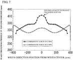
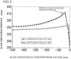
- FIG 7 illustrates a thickness profile at the top end of the slab.
- FIG. 8 illustrates a thickness distribution of the slab width center in the longitudinal direction. Local thickness increase in the slab-topmost-end portion is reduced, and the effect on reducing pass number of rough rolling and solving the problem of conveying trouble of the slab can be expected.
- the present invention was applied to the case where a slab with a width of 1650 mm and a slab thickness of 260 mm was set as a target and the reduction amount of the width of a slab was 250 mm by one reduction of the width of a slab.
- a problem of a thickness increase does not occur, but fish-tail deformation becomes remarkable.
- a description will be given of the fish-tail reducing effect by applying a compressive force under this condition.
- the reduction of the width of a slab was started from a mold inclined portion. Compressive forces of 7 MPa and 9 MPa were applied against a backward component force.
- FIG. 9 illustrates a top-end plain view pattern after the reduction of the width of the slab. Application of an appropriate compressive force was confirmed to allow controlling the top-end plain view pattern and reducing crop loss by 92%.
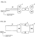
- FIG. 2A and FIG. 2B are respectively a side view and a plan view illustrating the outline of the shape control equipment of the hot slab according to the present invention described in the above-described (2).
- the shape control equipment according to the present invention is equipment that adjusts the shape of a hot slab extracted from a heating furnace (not illustrated).
- This shape control equipment includes a width pressing machine 2, an entry-side rolling mill 1, and an exit-side rolling mill 3.
- the width pressing machine 2 reduces the width of the slab by a pair of right and left molds.
- the entry-side rolling mill 1 and the exit-side rolling mill 3 are respectively arranged at an entry side that is the upstream side of a width pressing machine and at an exit side that is the downstream side, close to the width pressing machine 2.
- the entry-side rolling mill 1 and the exit-side rolling mill 3 each perform horizontal rolling on the slab by a pair of upper and lower rolls.
- the entry-side rolling mill 1 and exit-side rolling mill 3 have a distance between the respective roll axial centers within a slab length after reduction of the width of the slab.
- a shape control method the above-described shape control equipment was used to reduce the width of the hot slab extracted from the heating furnace once or twice or more by the width pressing machine 2 over the entire length of the slab.
- a compressive force and a tensile force were applied during the reduction of the width of a slab at the top and tail ends of slab using horizontal rolling by the entry-side and exit-side rolling mills.
- a compressive force was applied by the entry-side rolling mill at the time of rolling start of the exit-side rolling mill.
- FIG. 10A and FIG. 10B are charts illustrating respective results of compressive forces that are allowed to push the slab to the width pressing machine by the respective entry-side and exit-side rolling mills.
- the neutral point (in flat rolling) moves to the roll bite exit side as a pushing force from the roll bite exit side (a compressive force from the rolling mill to the width pressing machine) increases.
- a slip does not occur insofar as the compressive force is 11.0 MPa or less.
- the neutral point (in flat rolling) moves to the roll bite exit side as a pushing force from the roll bite exit side (a compressive force from the rolling mill to a sizing press machine) increases.
- a slip does not occur insofar as the compressive force is 17.2 MPa or less.
- the shape control equipment with the configuration illustrated in FIG. 2A and FIG. 2B (where the distance between the roll axial centers in the entry-side rolling mill and the exit-side rolling mill ⁇ the initial slab length) was used to reduce the width of a slab, which has a width of 1450 mm and a thickness of 260 mm as the initial size, over the entire length by 250 mm once using the width pressing machine. At this time, the width adjustment was performed under two conditions.
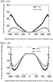
- the two conditions includes the case (an example of the present invention) where a compressive force of 7.7 MPa was applied in the slab travelling direction by the entry-side rolling mill during reduction of the width of a slab in the top end portion and a compressive force of 7.7 MPa was applied in the slab travelling direction by the exit-side rolling mill during reduction of the width of a slab in the tail end portion, and also includes the case (a comparative example) where the compressive force was not applied. Then, the respective amounts of crop loss were compared. As a result, as illustrated in FIG. 11A and FIG.
- the plain view pattern of the top and tail ends of slab after the width adjustment had a shape close to a rectangular shape compared with the comparative example (with black circles).
- the top-end crop weight was reduced by 84.3% compared with the comparative example (the calculating formula: (1 - the crop loss weight of the example of the present invention/the crop loss weight of the comparative example) ⁇ 100 (%)
- the tail-end crop weight was reduced by 22.3% compared with the comparative example (the calculating formula: (1 - the crop loss weight of the example of the present invention/the crop loss weight of the comparative example) ⁇ 100 (%)).
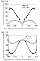
- the same shape control equipment as used in Working Example 3 was used to reduce the width of a slab, which has a width of 1450 mm and a thickness of 260 mm as the initial size, over the entire length by 325 mm twice for each reduction of the width of a slab, that is, by 650 mm in total using the width pressing machine. At this time, the width adjustment was performed under two conditions.
- the two conditions includes the case (an example of the present invention) where a compressive force of 7.7 MPa was applied in the slab travelling direction by the entry-side rolling mill during reduction of the width of a slab in the top end portion and a compressive force of 7.7 MPa was applied in the slab travelling direction by the exit-side rolling mill during reduction of the width of a slab in the tail end portion for each reduction of the width of a slab, and also includes the case (a comparative example) where the compressive force was not applied. Then, the respective amounts of crop loss were compared. As a result, as illustrated in FIG. 12A and FIG.
- the plain view pattern of the top and tail ends of slab after the width adjustment had a shape close to a rectangular shape compared with the comparative example (with black circles).
- the top-end crop weight was reduced by 85.0% compared with the comparative example (the calculating formula: (1 - the crop loss weight of the example of the present invention/the crop loss weight of the comparative example) ⁇ 100 (%)
- the tail-end crop weight is reduced by 80.5% compared with the comparative example (the calculating formula: (1 - the crop loss weight of the example of the present invention/the crop loss weight of the comparative example) ⁇ 100 (%)).
- the same shape control equipment as used in Working Example 3 was used to reduce the width of a slab, which has a width of 900 mm and a thickness of 260 mm as the initial slab size, over the entire length by 350 mm once using the width pressing machine. Subsequently, the width adjustment was performed under a plurality of conditions.
- the conditions include the case (an example of the present invention) where various compressive forces (pressing pressures) were applied in the slab travelling direction by the entry-side rolling mill at the start of horizontal rolling (during biting of the top end) at the time of the horizontal rolling by the exit-side rolling mill, and also includes the case (a comparative example) where the compressive force was not applied.
- an exit-side slab thickness (abbreviated as an exit-side rolling-mill exit-side thickness), a rolling reduction, a biting angle (specifically, the upper limit of the biting angle), and a rolling force were investigated, and the result is shown in Table 1.
- Table 1 Condition No. Pressing pressure (MPa) Exit-side rolling-mill exit-side thickness (mm) Rolling reduction (%) Biting angle (degree) Rolling force (t) Remarks 1 0.0 316 18 21 394 Comparativ e example 2 3.0 190 50 36 879 Example of the present invention 3 5.0 150 60 39 1029 Example of the present invention 4 7.0 120 68 42 1221 Example of the present invention 5 10.0 90 77 44 1380 Example of the present invention
- the slab After reduction of the width of a slab (at the entry-side of the exit-side rolling-mill), the slab increased in thickness up to 400 mm in the width center of the slab-top-end portion.
- the exit-side rolling-mill exit-side thickness was larger than the initial slab thickness of 260 mm in the comparative example where the pressing pressure was not applied. Additionally, the rolling reduction, the biting angle, the rolling force were all at low level, and reduction in pass number during rough rolling as the subsequent process (and productivity improvement due to this reduction) could not be expected. In contrast, in the example of the present invention where the pressing pressure was applied, the exit-side rolling-mill exit-side thickness considerably decreased as the pressing pressure increased. Thus, the rolling reduction, the biting angle, and the rolling force all increased.
- a pressing pressure of 10 MPa can reduce the exit-side rolling-mill exit-side thickness to one-third or less of that in the comparative example, and can increase the biting angle twice or more times. This led to reduction in pass number during the rough rolling as the subsequent process and led to productivity improvement due to this reduction.
- the rolling force was increased about three times at most compared with the comparative example, this rolling force was within a range of the device capacity. Thus, this did not cause a problem.
Description
- The present invention relates to shape control equipment and a shape control method for a hot slab. Specifically, the present invention relates to a shape control equipment and a shape control method for a hot slab that control a plain view pattern of top and tail ends of slab when a thickness and a width of a slab produced by continuous casting are shaped so as to reduce crop loss and that reduce a local thickness increase at the width center of the top end of the slab so as to solve a problem of reducing pass number of rough rolling and conveying trouble.
- The casting speed of a slab casted by a continuous casting machine hardly depends on the slab width. Therefore, in order to improve productivity, a method for casting a slab with a large width and reducing the width of the slab to a predetermined slab width corresponding to the product width in a hot-rolling line. As a device that reduces the width of a slab, a sizing mill and a sizing press have been developed and are used. This sizing mill is a device that performs slab-width rolling with rolling rolls mutually opposed on both sides in a slab width direction. However, the contact length of the rolls and the slab is short. Therefore, shear deformation to end portions of the slab width is large. This leads to a concave shape in the top and tail ends of slab that is referred to as fish tail, thus causing yield degradation. Because of this background, in order to increase the contact length with the slab to suppress the fish tail, the sizing press has been developed so as to achieve significant improvement in the yield. In the processing by this sizing press, width reducing load is approximately proportional to the contact length between the slab and the mold. Accordingly, from the aspect of load limitation of the equipment, the width is changed up to about 300 mm. However, the width of a typical hot-rolled steel strip product varies from about 700 mm to 2200 mm. Even in the case where the sizing press device is utilized in the hot-rolling line, it is necessary to cast slabs with widths at a plurality of levels by other chances in the continuous casting process.
- In the case where the reduction amount of the width of a slab is increased by increasing capacity of the sizing press, the following two problems occur in the sizing press processing. One of the problems is a problem A that heavy width reduction increases the slab-top-end width and increases the pass number of rough rolling after the width press, thus reducing production efficiency. Another problem is a problem B that a slab non-constant portion (both end portions in the longitudinal direction) cannot be formed to have a plain view pattern in a rectangular shape and crop loss increases after rough rolling as illustrated in
FIG. 14 , thus deteriorating yield. - For the problem A, conventionally, in order to improve biting property after reduction of the width of a slab, a known method A increases a mold inclined angle θ illustrated in
FIG. 15 and controls the increased thickness position in the slab thickness direction so as to prevent the thickness increase (see Patent Literature 1). However, in the case where the slab width is narrow or in the case where the reduction amount of the width of a slab is large, the effect is small. For the above-described problem B, conventionally, a known method B illustrated inFIG 16 adjusts a contact length L between the slab and the mold so as to adjust the shapes of the top and tail ends (see Patent Literature 2). - On the other hand, as a method for expanding the amount of the width change of the continuous-casting slab while reducing the concave shape referred to as a fish tail, which causes deterioration in yield, in the top and tail ends without increasing the load on the equipment, a method that is a combination of the sizing mill and the sizing press has been proposed (see Patent Literature 3). This is a method for changing the width of a constant portion by the sizing mill after preforming the top and tail ends of slab by the sizing press in advance so as to prevent the fish tail. This achieves a large width change of about 650 mm. When preforming by the sizing press significantly changes the width, the thickness of the top end of the slab increases and the slab collides with the roll for conveyance. This makes the conveyance difficult. Accordingly, a device that is devised to mechanically correct the top end of the slab by a lower roll, which is disposed on a conveyor line and can apply upward load, and this device is operated (see Patent Literature 4).
-
- Patent Literature 1: Japanese Unexamined Patent Application Publication No.
2009-6361 - Patent Literature 2: Japanese Patent No.
2561251 - Patent Literature 3: Japanese Unexamined Patent Application Publication No.
2008-254036 - Patent Literature 4: Japanese Unexamined Patent Application Publication No.
2008-254033 - Further prior art may be found in
JP S55 5103 A JP H01 284401 A JP H07 275901 A JP S55 5103 A JP S55 5103
Finally, inJP H07 275901 A - However, the above-described conventional techniques have the following problems. The conventional method A has a small effect on reduction in increase of the slab-top-end width. This does not lead to significant improvement in efficiency. Since the angle of the mold is constant, a sufficient effect cannot be obtained depending on the slab width. Since the mold length in the conventional method B is limited, the effect has a limitation. The reduction effect in thickness increase is not specifically mentioned, and the effect is considered to be poor.
- In
Patent Literature 3, the amount of the width change per one pass is small in a vertical rolling mill. In order to increase the width change of the slab, a high rolling pass number is required. Therefore, productivity becomes poor and the slab temperature is reduced. Furthermore, for heavy width reduction in the top end of the slab by the sizing press, a considerable thickness increase occurs in the top end portion. Accordingly, introduction of the correction device as described inPatent Literature 4 becomes a precondition. Thus, there are problems in many points such as installation space, equipment cost, and running cost. - That is, there is a problem that the conventional techniques cannot minimize yield loss and increase in slab thickness due to unsteady deformation in the top and rear end portions during reduction of the width of a slab and cannot shape the slab to have desired target dimensions at high productivity.
- Through long and intensive research carried out by the inventors of the present invention in order to solve the above problems, the present invention according to the following summary of configurations was made.
- (1) Shape control equipment for adjusting a width, a top-end plain view pattern, and a thickness profile of a slab. The slab is a hot slab extracted from a heating furnace. The shape control equipment includes a horizontal rolling mill and a width pressing machine. The horizontal rolling mill includes horizontal rolling rolls mutually opposed on both sides in a slab thickness direction. The width pressing machine includes a pair of width press molds mutually opposed on both sides in the slab width direction. The entry-side horizontal rolling mill as the horizontal rolling mill and the width pressing machine are installed in this order at an arrangement interval shorter than a slab length during extraction from heating furnace from an upstream side in a slab conveying direction.
- (2) In the shape control equipment for the hot slab according to (1), an exit-side horizontal rolling mill with a pair of horizontal rolling rolls are disposed close to a downstream side of the width pressing machine, the entry-side horizontal rolling mill, the width pressing machine, and the exit-side horizontal rolling mill are installed in this order from the upstream side in the slab conveying direction
- (3) A shape control method for a hot slab uses the shape control equipment for the hot slab according to (1) as a method for shape control of a hot slab. The shape control method includes simultaneously performing rolling by the horizontal rolling mill and reduction of a width of a slab by the width pressing machine on one hot slab.
- (4) In the shape control method for the hot slab according to (3), the shape control method includes performing a rolling speed control of the horizontal rolling mill during the reduction of the width of the slab by the width pressing machine.
- (5) A shape control method for a hot slab uses the shape control equipment according to (2). The shape control method includes applying a compressive force and a tensile force by horizontal rolling using the entry-side and exit-side horizontal rolling mills during reduction of the width of the slab in top and tail ends of slab, and applying a compressive force by the entry-side horizontal rolling mill at a time of rolling start of the exit-side horizontal rolling mill when reducing the width of the hot slab extracted from the heating furnace over an entire length of the slab once or twice or more by the width pressing machine.
- The present invention keeps a small fish-tail shape in the top and tail ends due to a width change of the slab during sizing press process and prevents conveying trouble, defective biting during horizontal rolling of the slab after the width change by the rough rolling mill in the downstream side, and a local thickness increase in the width center of the top end of the slab causing an increase in pass number. Additionally, the present invention can significantly change the width while maintaining excellent shapes at the top and tail ends. Thus, improvement in yield and improvement in efficiency of the continuous casting machine can be expected.
-
-
FIG. 1A and FIG. 1B are respectively a side view and a plan view illustrating an outline of shape control equipment for a hot slab according to the present invention described in claim 1. -
FIG. 2A and FIG. 2B are respectively a side view and a plan view illustrating an outline of a shape control equipment of a hot slab according to the present invention described inclaim 2. -
FIG. 3 is an explanatory view illustrating a backward component force during reduction of the width of a slab by a conventional width pressing machine. -
FIG. 4 is an explanatory view illustrating a thickness increase in the slab width center in the case where a fish tail portion is formed by conventional reduction of the width of a slab. -
FIG. 5 is a chart illustrating a movement example of the neutral point (in flat rolling) when load of a compressive force is applied from the downstream side of the horizontal rolling mill. -
FIG. 6 is a chart illustrating an exemplary modification of a plain view pattern of a slab-top-end portion after width press in Working Example 1. -
FIG. 7 is a chart illustrating an exemplary modification of a thickness distribution of the slab-top-end portion after width press with respect to a slab width direction in Working Example 1. -
FIG. 8 is a chart illustrating an exemplary modification of the thickness distribution of the slab width center after width press with respect to the longitudinal direction in Working Example 1. -
FIG. 9 is a chart illustrating an exemplary modification of a plain view pattern of the slab-top-end portion after width press in Working Example 2. -
FIG. 10A and FIG. 10B are charts illustrating an exemplary movement of the neutral point (in flat rolling) when load of compressive forces are applied by entry-side and exit-side rolling mills, respectively. -
FIG. 11A and FIG. 11B are charts illustrating plain view patterns of top and tail end portions of slab after width adjustment in an example of the present invention and a comparative example. -
FIG 12A and FIG. 12B are charts illustrating plain view patterns of the top and tail end portions of slab after width adjustment in an example of the present invention and a comparative example. -
FIG. 13 is a side view illustrating the outline of a width adjustment method in Working Example 3. -
FIG. 14 is a plan view illustrating crop loss of a sheet bar after rough rolling. -
FIG. 15 is a plan view illustrating a mold inclined angle θ. -
FIG. 16 is a plan view illustrating a contact length L between a slab and a mold. - The following describes embodiments of the present invention with operations and effects. In the following description, "load" and "force" are both amounts per unit area. In reduction of the width of a slab by ordinary sizing press, since the mold stroke is not adequate to increase the amount of the reduction of the width of a slab, the reduction of the width of a slab begins from an inclined portion of a
mold 2K. At this time, the amount of fish tail in the top end of the slab increases with increasing mold inclined angle. This locally increases the thickness in the center of the slab-top-end slab width. - The inventors studied, in detail, a slab-top-end deformation mechanism caused by reducing the width of a slab by the sizing press. As a result, the inventors conceived an advantageous control method for the deformation. In reduction of the width of a slab by the sizing press, a width reducing load P is decomposed into a mold inclined angle θ so as to generate a force Psinθ that moves the slab backward as illustrated in
FIG. 3 . On the other hand, a friction force µP (µ indicates a friction coefficient) acts in the contact area between themold 2K and aslab 10. The horizontal component force uPcosθ blocks the backward movement of theslab 10. With these two forces, a large shear force occurs in the slab-top-end portion and a fish tail portion 10FT is formed along with the backward movement of theslab 10. The shear force by this backward component force Psinθ increases with increasing mold inclined angle θ. - In the case where the slab-top-end shape becomes a fish tail, a local increase in thickness of a slab width center 10WC is caused in the slab-top-end portion.
FIG. 4 illustrates a mechanism of a thickness increase of the slab width center 10WC after the top end of the slab becomes to have a fish-tail shape and illustrates the appearance of a longitudinal thickness distribution of the slab width center 10WC after the thickness increase. When the fish tail portion 10FT is formed at the top end, a portion without material (a material-missing portion) is formed at the top end of the slab. Accordingly, restriction of the material is released in this portion. This reduces the plastic strain amount of the fish tail portion 10FT without receiving a reactive force from the material. On the other hand, the volume of the material to be deformed by reducing the width of a slab is constant. Accordingly, deformation concentrates on the slab width center 10WC in the slab-top-end portion, thus causing a local thickness increase. - With the above-described mechanism, the top end fish tail and the local thickness increase of the slab thickness are considered to be effectively reduced by reduction of the backward component force, which is a root cause of these problems. An embodiment of the present invention will be described by referring to
FIG. 1A and FIG 1B. FIG. 1A and FIG. 1B are respectively a side view and a plan view illustrating the outline of the shape control equipment for the hot slab according to the present invention described in the above-described (1). A horizontal rolling mill 1 includes horizontal rolling rolls 1 HR mutually opposed on both sides in the slab thickness direction. Awidth pressing machine 2 includes a pair of molds (width press molds) 2K mutually opposed on both sides in the slab width direction. The horizontal rolling mill 1 and thewidth pressing machine 2 are installed in this order from the upstream side of the slab conveying direction at an arrangement interval η shorter than the slab length during extraction from heating furnace. That is, the slab length during extraction from heating furnace is expressed with L0 as 0 < η < L0, preferably, 0 < η < 0.3 × L0. - With this equipment, slab thickness rolling by the horizontal rolling mill 1 and reduction of the width of a slab by the
width pressing machine 2 are simultaneously performed on one hot slab. This allows applying a compressive force against the above-described backward component force Psinθ to the slab by transfer using the horizontal rolling rolls 1HR of the horizontal rolling mill 1 at the upstream side of themold 2K during reduction of the width of a slab by themolds 2K of thewidth pressing machine 2, thus controlling the top-end shape. This method reduces fish tail in the top end portion independently of the slab width or the reduction amount of the width of a slab and allows heavy width reduction while reducing a local thickness increase caused by the fish tail portion in the slab width center. - Here, the horizontal rolling mill 1 is preferred to perform rolling speed control such that a rolling slip does not occur and the compressive force acts on the slab at the exit side of the horizontal rolling mill. The occurrence condition of a slip during rolling can be determined based on whether or not the neutral point (in flat rolling) exists in a roll bite.
FIG. 5 illustrates the result of performing rolling analysis assuming that the horizontal rolling mill applies load of a compressive force. In the analysis condition, the horizontal width of a slab equivalent to have a thickness of 260 mm and a temperature of 1000°C was reduced to have a thickness of 245 mm in a roll with ϕ 1000 mm. From the downstream of the horizontal rolling mill, applying load of a pushing force moves the neutral point (in flat rolling) to the exit side of the roll bite. In this rolling condition, it was found that a pushing force of about 11 MPa or less did not cause a slip. With this pushing force, that is, compressive force, a shape control of the slab-top-end portion was performed. - As Working Example 1, the present invention was applied to the case where a slab with a width of 1450 mm and a slab thickness of 260 mm was set as a target and reduction of the width of a slab by 325 mm for each reduction was performed twice so as to reduce 650 mm in the total reduction amount of the width of a slab. The reduction of the width of a slab was started from a mold inclined portion. Only at the time of the first pass, a compressive force of 9 MPa against the backward component force was applied by the horizontal rolling mill.
FIG. 6 illustrates a top-end plain view pattern after the reduction of the width of a slab. Ordinary reduction of the width of a slab (with a compressive force of 0 MPa) results in a huge fish-tail shape. However, the condition with application of a compressive force allowed reducing the fish-tail shape, thus cutting 76.2% of the crop loss.FIG 7 illustrates a thickness profile at the top end of the slab. Application of a compressive force allowed reducing the increase in thickness of the top end portion by about 15%.FIG. 8 illustrates a thickness distribution of the slab width center in the longitudinal direction. Local thickness increase in the slab-topmost-end portion is reduced, and the effect on reducing pass number of rough rolling and solving the problem of conveying trouble of the slab can be expected. - As Working Example 2, the present invention was applied to the case where a slab with a width of 1650 mm and a slab thickness of 260 mm was set as a target and the reduction amount of the width of a slab was 250 mm by one reduction of the width of a slab. Under a condition where the reduction amount of the width of a slab is small with respect to the slab width, a problem of a thickness increase does not occur, but fish-tail deformation becomes remarkable. A description will be given of the fish-tail reducing effect by applying a compressive force under this condition. The reduction of the width of a slab was started from a mold inclined portion. Compressive forces of 7 MPa and 9 MPa were applied against a backward component force.
FIG. 9 illustrates a top-end plain view pattern after the reduction of the width of the slab. Application of an appropriate compressive force was confirmed to allow controlling the top-end plain view pattern and reducing crop loss by 92%. -
FIG. 2A and FIG. 2B are respectively a side view and a plan view illustrating the outline of the shape control equipment of the hot slab according to the present invention described in the above-described (2). As illustrated in the drawings, the shape control equipment according to the present invention is equipment that adjusts the shape of a hot slab extracted from a heating furnace (not illustrated). This shape control equipment includes awidth pressing machine 2, an entry-side rolling mill 1, and an exit-side rolling mill 3. Thewidth pressing machine 2 reduces the width of the slab by a pair of right and left molds. The entry-side rolling mill 1 and the exit-side rolling mill 3 are respectively arranged at an entry side that is the upstream side of a width pressing machine and at an exit side that is the downstream side, close to thewidth pressing machine 2. The entry-side rolling mill 1 and the exit-side rolling mill 3 each perform horizontal rolling on the slab by a pair of upper and lower rolls. The entry-side rolling mill 1 and exit-side rolling mill 3 have a distance between the respective roll axial centers within a slab length after reduction of the width of the slab. - In a shape control method according to the present invention, the above-described shape control equipment was used to reduce the width of the hot slab extracted from the heating furnace once or twice or more by the
width pressing machine 2 over the entire length of the slab. At this time, a compressive force and a tensile force were applied during the reduction of the width of a slab at the top and tail ends of slab using horizontal rolling by the entry-side and exit-side rolling mills. Additionally, a compressive force was applied by the entry-side rolling mill at the time of rolling start of the exit-side rolling mill. It is important to apply the compressive force and the tensile force so as to satisfy the condition where the rolling neutral points in flat rolling in the entry-side and exit-side rolling mills are present in a roll bite (the condition not to cause a slip). The range of the compressive force that satisfies this condition can be calculated from rolling theory. For example,FIG. 10A and FIG. 10B are charts illustrating respective results of compressive forces that are allowed to push the slab to the width pressing machine by the respective entry-side and exit-side rolling mills. The calculation conditions are set as initial slab size = 260 mm thickness × 1450 mm width, temperature = 1100°C, roll diameter = 1000 mmφ, friction coefficient = 0.3, and exit-side thicknesses of the respective entry-side and exit-side horizontal rolling mills = 245 mm. - According to
FIG. 10A , in the entry-side rolling mill, the neutral point (in flat rolling) moves to the roll bite exit side as a pushing force from the roll bite exit side (a compressive force from the rolling mill to the width pressing machine) increases. However, a slip does not occur insofar as the compressive force is 11.0 MPa or less. According toFIG. 10B , in the exit-side rolling mill, the neutral point (in flat rolling) moves to the roll bite exit side as a pushing force from the roll bite exit side (a compressive force from the rolling mill to a sizing press machine) increases. However, a slip does not occur insofar as the compressive force is 17.2 MPa or less. - The shape control equipment with the configuration illustrated in
FIG. 2A and FIG. 2B (where the distance between the roll axial centers in the entry-side rolling mill and the exit-side rolling mill ≤ the initial slab length) was used to reduce the width of a slab, which has a width of 1450 mm and a thickness of 260 mm as the initial size, over the entire length by 250 mm once using the width pressing machine. At this time, the width adjustment was performed under two conditions. The two conditions includes the case (an example of the present invention) where a compressive force of 7.7 MPa was applied in the slab travelling direction by the entry-side rolling mill during reduction of the width of a slab in the top end portion and a compressive force of 7.7 MPa was applied in the slab travelling direction by the exit-side rolling mill during reduction of the width of a slab in the tail end portion, and also includes the case (a comparative example) where the compressive force was not applied. Then, the respective amounts of crop loss were compared. As a result, as illustrated inFIG. 11A and FIG. 11B , in the example of the present invention (with white circles), the plain view pattern of the top and tail ends of slab after the width adjustment had a shape close to a rectangular shape compared with the comparative example (with black circles). As a result, (a) the top-end crop weight was reduced by 84.3% compared with the comparative example (the calculating formula: (1 - the crop loss weight of the example of the present invention/the crop loss weight of the comparative example) × 100 (%)), and (b) the tail-end crop weight was reduced by 22.3% compared with the comparative example (the calculating formula: (1 - the crop loss weight of the example of the present invention/the crop loss weight of the comparative example) × 100 (%)). - The same shape control equipment as used in Working Example 3 was used to reduce the width of a slab, which has a width of 1450 mm and a thickness of 260 mm as the initial size, over the entire length by 325 mm twice for each reduction of the width of a slab, that is, by 650 mm in total using the width pressing machine. At this time, the width adjustment was performed under two conditions. The two conditions includes the case (an example of the present invention) where a compressive force of 7.7 MPa was applied in the slab travelling direction by the entry-side rolling mill during reduction of the width of a slab in the top end portion and a compressive force of 7.7 MPa was applied in the slab travelling direction by the exit-side rolling mill during reduction of the width of a slab in the tail end portion for each reduction of the width of a slab, and also includes the case (a comparative example) where the compressive force was not applied. Then, the respective amounts of crop loss were compared. As a result, as illustrated in
FIG. 12A and FIG. 12B , in the example of the present invention (with white circles), the plain view pattern of the top and tail ends of slab after the width adjustment had a shape close to a rectangular shape compared with the comparative example (with black circles). As a result, (a) the top-end crop weight was reduced by 85.0% compared with the comparative example (the calculating formula: (1 - the crop loss weight of the example of the present invention/the crop loss weight of the comparative example) × 100 (%)), and (b) the tail-end crop weight is reduced by 80.5% compared with the comparative example (the calculating formula: (1 - the crop loss weight of the example of the present invention/the crop loss weight of the comparative example) × 100 (%)). - The same shape control equipment as used in Working Example 3 was used to reduce the width of a slab, which has a width of 900 mm and a thickness of 260 mm as the initial slab size, over the entire length by 350 mm once using the width pressing machine. Subsequently, the width adjustment was performed under a plurality of conditions. The conditions include the case (an example of the present invention) where various compressive forces (pressing pressures) were applied in the slab travelling direction by the entry-side rolling mill at the start of horizontal rolling (during biting of the top end) at the time of the horizontal rolling by the exit-side rolling mill, and also includes the case (a comparative example) where the compressive force was not applied. Regarding the exit-side rolling mill, an exit-side slab thickness (abbreviated as an exit-side rolling-mill exit-side thickness), a rolling reduction, a biting angle (specifically, the upper limit of the biting angle), and a rolling force were investigated, and the result is shown in Table 1.
[Table 1] Condition No. Pressing pressure (MPa) Exit-side rolling-mill exit-side thickness (mm) Rolling reduction (%) Biting angle (degree) Rolling force (t) Remarks 1 0.0 316 18 21 394 Comparativ e example 2 3.0 190 50 36 879 Example of the present invention 3 5.0 150 60 39 1029 Example of the present invention 4 7.0 120 68 42 1221 Example of the present invention 5 10.0 90 77 44 1380 Example of the present invention - After reduction of the width of a slab (at the entry-side of the exit-side rolling-mill), the slab increased in thickness up to 400 mm in the width center of the slab-top-end portion. According to Table 1, the exit-side rolling-mill exit-side thickness was larger than the initial slab thickness of 260 mm in the comparative example where the pressing pressure was not applied. Additionally, the rolling reduction, the biting angle, the rolling force were all at low level, and reduction in pass number during rough rolling as the subsequent process (and productivity improvement due to this reduction) could not be expected. In contrast, in the example of the present invention where the pressing pressure was applied, the exit-side rolling-mill exit-side thickness considerably decreased as the pressing pressure increased. Thus, the rolling reduction, the biting angle, and the rolling force all increased. A pressing pressure of 10 MPa can reduce the exit-side rolling-mill exit-side thickness to one-third or less of that in the comparative example, and can increase the biting angle twice or more times. This led to reduction in pass number during the rough rolling as the subsequent process and led to productivity improvement due to this reduction. Here, although the rolling force was increased about three times at most compared with the comparative example, this rolling force was within a range of the device capacity. Thus, this did not cause a problem.
-
- 1 entry-side horizontal rolling mill
- 1HR entry-side horizontal rolling roll
- 2 width pressing machine
- 2K mold (width press mold)
- 3 exit-side rolling mill
- 3HR exit-side horizontal rolling roll
- 10 slab (hot slab)
- 10WC slab width center
- 10FT fish tail portion
- η arrangement interval between horizontal rolling mill and width pressing machine
- P width reducing load
- θ mold inclined angle
- µ friction coefficient
Claims (6)
- Shape control equipment for adjusting a slab width, a top-end plain view pattern, and a slab thickness profile of a slab (10), the slab being a hot slab extracted from a heating furnace, the shape control equipment comprising:a horizontal rolling mill (1) that includes horizontal rolling rolls (1HR) mutually opposed on both sides in a slab thickness direction; anda width pressing machine (2) that includes a pair of width press molds (2K) mutually opposed on both sides in the slab width direction, whereinan entry-side horizontal rolling mill (1) as the horizontal rolling mill and the width pressing machine are installed in this order at an arrangement interval (η) shorter than a slab length (L0) during extraction from a heating furnace from an upstream side in a slab conveying direction,characterised in that the horizontal mill (1) is configured to perform a rolling speed control during the reduction of the width of the slab by the width pressing machine (2) such that a rolling slip does not occur and the compressive force acts on the slab at the exit side of the horizontal rolling mill.
- The shape control equipment for the hot slab according to claim 1, further comprising
an exit-side horizontal rolling mill (3) as the horizontal rolling mill disposed close to a downstream side of the width pressing machine, the exit-side horizontal rolling mill including a pair of horizontal rolling rolls (3HR), wherein
the entry-side horizontal rolling mill, the width pressing machine, and the exit-side horizontal rolling mill are installed in this order from the upstream side in the slab conveying direction. - A shape control method for a hot slab using the shape control equipment for the hot slab according to claim 1, the shape control method comprising
simultaneously performing rolling by the horizontal rolling mill and reduction of a width of a slab by the width pressing machine on one hot slab, and being characterised by
performing a rolling speed control of the horizontal rolling mill during the reduction of the width of the slab by the width pressing machine such that a rolling slip does not occur and the compressive force acts on the slab at the exit side of the horizontal rolling mill. - A shape control method for a hot slab using the shape control equipment according to claim 2, the shape control method comprising
applying a compressive force and a tensile force by horizontal rolling using the entry-side and exit-side horizontal rolling mills during reduction of the width of the slab in top and tail ends of slab, and applying a compressive force by the entry-side horizontal rolling mill at a time of rolling start of the exit-side horizontal rolling mill when reducing the width of the hot slab extracted from the heating furnace over an entire length of the slab once or twice or more by the width pressing machine. - The shape control equipment according to claim 1 or 2, wherein
the arrangement interval (η) is 0 < η < L0, preferably 0 < η < 0.3 x L0, wherein L0 expresses the slab length during extraction from the heating furnace. - The shape control equipment for the hot slab according to claim 2, wherein
a distance between roll axial centers in the entry-side rolling mill and the exit-side rolling mill ≤ a slab length after reduction of the width of the slab.
Applications Claiming Priority (4)
| Application Number | Priority Date | Filing Date | Title |
|---|---|---|---|
| JP2011233608 | 2011-10-25 | ||
| JP2012043022 | 2012-02-29 | ||
| JP2012160083A JP5962283B2 (en) | 2011-10-25 | 2012-07-19 | Hot slab shape adjustment method |
| PCT/JP2012/006639 WO2013061542A1 (en) | 2011-10-25 | 2012-10-17 | Hot slab shape control equipment and shape control method |
Publications (3)
| Publication Number | Publication Date |
|---|---|
| EP2762241A1 EP2762241A1 (en) | 2014-08-06 |
| EP2762241A4 EP2762241A4 (en) | 2015-06-24 |
| EP2762241B1 true EP2762241B1 (en) | 2017-12-13 |
Family
ID=48167398
Family Applications (1)
| Application Number | Title | Priority Date | Filing Date |
|---|---|---|---|
| EP12843671.4A Not-in-force EP2762241B1 (en) | 2011-10-25 | 2012-10-17 | Hot slab shape control equipment and shape control method |
Country Status (6)
| Country | Link |
|---|---|
| EP (1) | EP2762241B1 (en) |
| JP (1) | JP5962283B2 (en) |
| KR (1) | KR101661826B1 (en) |
| CN (1) | CN103906583B (en) |
| IN (1) | IN2014KN00761A (en) |
| WO (1) | WO2013061542A1 (en) |
Families Citing this family (3)
| Publication number | Priority date | Publication date | Assignee | Title |
|---|---|---|---|---|
| KR101639893B1 (en) * | 2014-11-21 | 2016-07-15 | 주식회사 포스코 | Apparatus and method for manufacturing billet |
| CN106890852A (en) * | 2015-12-21 | 2017-06-27 | 宝山钢铁股份有限公司 | Reduce the method that finishing mill stings steel impact |
| ES2804904T3 (en) * | 2016-05-13 | 2021-02-09 | Nippon Steel Corp | Beading method and beading apparatus |
Family Cites Families (16)
| Publication number | Priority date | Publication date | Assignee | Title |
|---|---|---|---|---|
| JPS555103A (en) * | 1978-06-23 | 1980-01-16 | Kawasaki Steel Corp | Edging method for slab |
| JP2561251B2 (en) | 1986-11-27 | 1996-12-04 | 石川島播磨重工業株式会社 | Slab rolling method |
| JPH01284401A (en) * | 1988-05-09 | 1989-11-15 | Ishikawajima Harima Heavy Ind Co Ltd | Method for edge pressing and device thereof |
| JP2811838B2 (en) * | 1989-12-05 | 1998-10-15 | 石川島播磨重工業株式会社 | Horizontal opposing press |
| JP2995903B2 (en) * | 1991-04-17 | 1999-12-27 | 石川島播磨重工業株式会社 | Metal plate manufacturing method |
| JP3223935B2 (en) * | 1993-03-19 | 2001-10-29 | 石川島播磨重工業株式会社 | Width reduction press |
| JPH0737402U (en) * | 1993-12-28 | 1995-07-11 | 株式会社東芝 | Sizing press control device |
| JPH07275901A (en) * | 1994-04-06 | 1995-10-24 | Nippon Steel Corp | Method for continuously edging hot slab |
| JPH10137802A (en) * | 1996-11-01 | 1998-05-26 | Nippon Steel Corp | Hot rolling method of slab |
| JP3991127B2 (en) * | 1997-09-16 | 2007-10-17 | 株式会社Ihi | Sheet thickness reduction method and apparatus |
| WO1999026737A1 (en) * | 1997-11-26 | 1999-06-03 | Ishikawajima-Harima Heavy Industries Co., Ltd. | Apparatus and method for changing metal molds for plate thickness reducing presses, and press metal die |
| JP2001018001A (en) * | 1999-07-05 | 2001-01-23 | Kobe Steel Ltd | Manufacturing equipment for high strength steel plate |
| BR0100836A (en) * | 2000-03-01 | 2001-10-30 | Ishikawajima Harima Heavy Ind | Apparatus and process for manufacturing a hot rolled steel plate, process and apparatus for pressing plate thickness and process for forming plate |
| JP5058657B2 (en) | 2007-04-05 | 2012-10-24 | 新日本製鐵株式会社 | Straightening method for edge forming slab |
| JP5042690B2 (en) | 2007-04-05 | 2012-10-03 | 新日本製鐵株式会社 | Slab width reduction equipment |
| JP2009006361A (en) | 2007-06-28 | 2009-01-15 | Jfe Steel Kk | Hot-rolling method |
-
2012
- 2012-07-19 JP JP2012160083A patent/JP5962283B2/en active Active
- 2012-10-17 IN IN761KON2014 patent/IN2014KN00761A/en unknown
- 2012-10-17 KR KR1020147011028A patent/KR101661826B1/en active IP Right Grant
- 2012-10-17 WO PCT/JP2012/006639 patent/WO2013061542A1/en active Application Filing
- 2012-10-17 EP EP12843671.4A patent/EP2762241B1/en not_active Not-in-force
- 2012-10-17 CN CN201280051703.6A patent/CN103906583B/en not_active Expired - Fee Related
Non-Patent Citations (1)
| Title |
|---|
| None * |
Also Published As
| Publication number | Publication date |
|---|---|
| IN2014KN00761A (en) | 2015-10-02 |
| CN103906583A (en) | 2014-07-02 |
| KR101661826B1 (en) | 2016-09-30 |
| EP2762241A1 (en) | 2014-08-06 |
| WO2013061542A1 (en) | 2013-05-02 |
| KR20140070624A (en) | 2014-06-10 |
| JP2013208648A (en) | 2013-10-10 |
| JP5962283B2 (en) | 2016-08-03 |
| EP2762241A4 (en) | 2015-06-24 |
| CN103906583B (en) | 2017-03-08 |
Similar Documents
| Publication | Publication Date | Title |
|---|---|---|
| CN108746213B (en) | Method for improving rolling stability of high-strength IF steel | |
| EP2762241B1 (en) | Hot slab shape control equipment and shape control method | |
| US8186422B2 (en) | Method for the continuous casting of thin metal strip and continuous casting installation | |
| KR101220738B1 (en) | Forging method of Heavy Thick Plate | |
| CN110860561A (en) | Method for coordinately controlling straight section of electrical steel through short-process cold rolling and hot rolling | |
| JP6172109B2 (en) | Hot rolled steel sheet rolling method | |
| JP6172107B2 (en) | Hot rolled steel sheet rolling method | |
| CN111250552B (en) | Method and device for avoiding deviation of plate blank | |
| JP6123745B2 (en) | Steel sheet rolling method | |
| JP6365626B2 (en) | Slab shape adjustment method | |
| CN105414183A (en) | Technology method for manufacturing wide sheet through magnesium alloy cast rolled plate | |
| CN109909302A (en) | A kind of slab casting-rolling method in continuous casting machine fan-shaped segment exit | |
| KR101438774B1 (en) | Rolling mill and rolling method | |
| CN105363781B (en) | Roll-casting of magnesium alloy plate prepares the rolling mill practice method of wide sheet blank | |
| JPH04147701A (en) | Cross sizing method for hot slab | |
| JP6747256B2 (en) | Method for manufacturing H-section steel | |
| CN112845584B (en) | Method for effectively controlling longitudinal shearing, splitting and side bending of hot-rolled strip steel | |
| JP5903826B2 (en) | Hot slab sizing rolling method | |
| JP3845345B2 (en) | Hot slab width reduction method | |
| RU2679159C1 (en) | Method of manufacture of specially thin hot-rolled stripes on a wide-striped mill of the casting complex | |
| JP2010075977A (en) | Method of forming slab with sizing press | |
| JP2023113156A (en) | Method for manufacturing hat-shaped steel sheet pile | |
| RU2465078C1 (en) | Method of reducing continuously cast slabs | |
| CN114888083A (en) | Method for rolling wide thin plate by medium plate mill | |
| KR101639893B1 (en) | Apparatus and method for manufacturing billet |
Legal Events
| Date | Code | Title | Description |
|---|---|---|---|
| PUAI | Public reference made under article 153(3) epc to a published international application that has entered the european phase |
Free format text: ORIGINAL CODE: 0009012 |
|
| 17P | Request for examination filed |
Effective date: 20140425 |
|
| AK | Designated contracting states |
Kind code of ref document: A1 Designated state(s): AL AT BE BG CH CY CZ DE DK EE ES FI FR GB GR HR HU IE IS IT LI LT LU LV MC MK MT NL NO PL PT RO RS SE SI SK SM TR |
|
| DAX | Request for extension of the european patent (deleted) | ||
| RA4 | Supplementary search report drawn up and despatched (corrected) |
Effective date: 20150526 |
|
| RIC1 | Information provided on ipc code assigned before grant |
Ipc: B21J 1/04 20060101ALI20150519BHEP Ipc: B21B 15/00 20060101AFI20150519BHEP Ipc: B21B 1/02 20060101ALI20150519BHEP |
|
| 17Q | First examination report despatched |
Effective date: 20160802 |
|
| GRAP | Despatch of communication of intention to grant a patent |
Free format text: ORIGINAL CODE: EPIDOSNIGR1 |
|
| INTG | Intention to grant announced |
Effective date: 20170628 |
|
| GRAS | Grant fee paid |
Free format text: ORIGINAL CODE: EPIDOSNIGR3 |
|
| GRAA | (expected) grant |
Free format text: ORIGINAL CODE: 0009210 |
|
| AK | Designated contracting states |
Kind code of ref document: B1 Designated state(s): AL AT BE BG CH CY CZ DE DK EE ES FI FR GB GR HR HU IE IS IT LI LT LU LV MC MK MT NL NO PL PT RO RS SE SI SK SM TR |
|
| REG | Reference to a national code |
Ref country code: GB Ref legal event code: FG4D |
|
| REG | Reference to a national code |
Ref country code: AT Ref legal event code: REF Ref document number: 953887 Country of ref document: AT Kind code of ref document: T Effective date: 20171215 Ref country code: CH Ref legal event code: EP |
|
| REG | Reference to a national code |
Ref country code: IE Ref legal event code: FG4D |
|
| REG | Reference to a national code |
Ref country code: DE Ref legal event code: R096 Ref document number: 602012040975 Country of ref document: DE |
|
| REG | Reference to a national code |
Ref country code: NL Ref legal event code: MP Effective date: 20171213 |
|
| REG | Reference to a national code |
Ref country code: LT Ref legal event code: MG4D |
|
| PG25 | Lapsed in a contracting state [announced via postgrant information from national office to epo] |
Ref country code: FI Free format text: LAPSE BECAUSE OF FAILURE TO SUBMIT A TRANSLATION OF THE DESCRIPTION OR TO PAY THE FEE WITHIN THE PRESCRIBED TIME-LIMIT Effective date: 20171213 Ref country code: LT Free format text: LAPSE BECAUSE OF FAILURE TO SUBMIT A TRANSLATION OF THE DESCRIPTION OR TO PAY THE FEE WITHIN THE PRESCRIBED TIME-LIMIT Effective date: 20171213 Ref country code: NO Free format text: LAPSE BECAUSE OF FAILURE TO SUBMIT A TRANSLATION OF THE DESCRIPTION OR TO PAY THE FEE WITHIN THE PRESCRIBED TIME-LIMIT Effective date: 20180313 Ref country code: SE Free format text: LAPSE BECAUSE OF FAILURE TO SUBMIT A TRANSLATION OF THE DESCRIPTION OR TO PAY THE FEE WITHIN THE PRESCRIBED TIME-LIMIT Effective date: 20171213 |
|
| REG | Reference to a national code |
Ref country code: AT Ref legal event code: MK05 Ref document number: 953887 Country of ref document: AT Kind code of ref document: T Effective date: 20171213 |
|
| PG25 | Lapsed in a contracting state [announced via postgrant information from national office to epo] |
Ref country code: GR Free format text: LAPSE BECAUSE OF FAILURE TO SUBMIT A TRANSLATION OF THE DESCRIPTION OR TO PAY THE FEE WITHIN THE PRESCRIBED TIME-LIMIT Effective date: 20180314 Ref country code: BG Free format text: LAPSE BECAUSE OF FAILURE TO SUBMIT A TRANSLATION OF THE DESCRIPTION OR TO PAY THE FEE WITHIN THE PRESCRIBED TIME-LIMIT Effective date: 20180313 Ref country code: HR Free format text: LAPSE BECAUSE OF FAILURE TO SUBMIT A TRANSLATION OF THE DESCRIPTION OR TO PAY THE FEE WITHIN THE PRESCRIBED TIME-LIMIT Effective date: 20171213 Ref country code: RS Free format text: LAPSE BECAUSE OF FAILURE TO SUBMIT A TRANSLATION OF THE DESCRIPTION OR TO PAY THE FEE WITHIN THE PRESCRIBED TIME-LIMIT Effective date: 20171213 Ref country code: LV Free format text: LAPSE BECAUSE OF FAILURE TO SUBMIT A TRANSLATION OF THE DESCRIPTION OR TO PAY THE FEE WITHIN THE PRESCRIBED TIME-LIMIT Effective date: 20171213 |
|
| PG25 | Lapsed in a contracting state [announced via postgrant information from national office to epo] |
Ref country code: NL Free format text: LAPSE BECAUSE OF FAILURE TO SUBMIT A TRANSLATION OF THE DESCRIPTION OR TO PAY THE FEE WITHIN THE PRESCRIBED TIME-LIMIT Effective date: 20171213 |
|
| PG25 | Lapsed in a contracting state [announced via postgrant information from national office to epo] |
Ref country code: ES Free format text: LAPSE BECAUSE OF FAILURE TO SUBMIT A TRANSLATION OF THE DESCRIPTION OR TO PAY THE FEE WITHIN THE PRESCRIBED TIME-LIMIT Effective date: 20171213 Ref country code: CY Free format text: LAPSE BECAUSE OF FAILURE TO SUBMIT A TRANSLATION OF THE DESCRIPTION OR TO PAY THE FEE WITHIN THE PRESCRIBED TIME-LIMIT Effective date: 20171213 Ref country code: EE Free format text: LAPSE BECAUSE OF FAILURE TO SUBMIT A TRANSLATION OF THE DESCRIPTION OR TO PAY THE FEE WITHIN THE PRESCRIBED TIME-LIMIT Effective date: 20171213 Ref country code: SK Free format text: LAPSE BECAUSE OF FAILURE TO SUBMIT A TRANSLATION OF THE DESCRIPTION OR TO PAY THE FEE WITHIN THE PRESCRIBED TIME-LIMIT Effective date: 20171213 Ref country code: CZ Free format text: LAPSE BECAUSE OF FAILURE TO SUBMIT A TRANSLATION OF THE DESCRIPTION OR TO PAY THE FEE WITHIN THE PRESCRIBED TIME-LIMIT Effective date: 20171213 |
|
| PG25 | Lapsed in a contracting state [announced via postgrant information from national office to epo] |
Ref country code: AT Free format text: LAPSE BECAUSE OF FAILURE TO SUBMIT A TRANSLATION OF THE DESCRIPTION OR TO PAY THE FEE WITHIN THE PRESCRIBED TIME-LIMIT Effective date: 20171213 Ref country code: IT Free format text: LAPSE BECAUSE OF FAILURE TO SUBMIT A TRANSLATION OF THE DESCRIPTION OR TO PAY THE FEE WITHIN THE PRESCRIBED TIME-LIMIT Effective date: 20171213 Ref country code: SM Free format text: LAPSE BECAUSE OF FAILURE TO SUBMIT A TRANSLATION OF THE DESCRIPTION OR TO PAY THE FEE WITHIN THE PRESCRIBED TIME-LIMIT Effective date: 20171213 Ref country code: IS Free format text: LAPSE BECAUSE OF FAILURE TO SUBMIT A TRANSLATION OF THE DESCRIPTION OR TO PAY THE FEE WITHIN THE PRESCRIBED TIME-LIMIT Effective date: 20180413 Ref country code: RO Free format text: LAPSE BECAUSE OF FAILURE TO SUBMIT A TRANSLATION OF THE DESCRIPTION OR TO PAY THE FEE WITHIN THE PRESCRIBED TIME-LIMIT Effective date: 20171213 Ref country code: PL Free format text: LAPSE BECAUSE OF FAILURE TO SUBMIT A TRANSLATION OF THE DESCRIPTION OR TO PAY THE FEE WITHIN THE PRESCRIBED TIME-LIMIT Effective date: 20171213 |
|
| REG | Reference to a national code |
Ref country code: DE Ref legal event code: R097 Ref document number: 602012040975 Country of ref document: DE |
|
| PLBE | No opposition filed within time limit |
Free format text: ORIGINAL CODE: 0009261 |
|
| STAA | Information on the status of an ep patent application or granted ep patent |
Free format text: STATUS: NO OPPOSITION FILED WITHIN TIME LIMIT |
|
| 26N | No opposition filed |
Effective date: 20180914 |
|
| PG25 | Lapsed in a contracting state [announced via postgrant information from national office to epo] |
Ref country code: DK Free format text: LAPSE BECAUSE OF FAILURE TO SUBMIT A TRANSLATION OF THE DESCRIPTION OR TO PAY THE FEE WITHIN THE PRESCRIBED TIME-LIMIT Effective date: 20171213 |
|
| PGFP | Annual fee paid to national office [announced via postgrant information from national office to epo] |
Ref country code: DE Payment date: 20181026 Year of fee payment: 7 |
|
| PG25 | Lapsed in a contracting state [announced via postgrant information from national office to epo] |
Ref country code: SI Free format text: LAPSE BECAUSE OF FAILURE TO SUBMIT A TRANSLATION OF THE DESCRIPTION OR TO PAY THE FEE WITHIN THE PRESCRIBED TIME-LIMIT Effective date: 20171213 |
|
| REG | Reference to a national code |
Ref country code: CH Ref legal event code: PL |
|
| GBPC | Gb: european patent ceased through non-payment of renewal fee |
Effective date: 20181017 |
|
| REG | Reference to a national code |
Ref country code: BE Ref legal event code: MM Effective date: 20181031 |
|
| PG25 | Lapsed in a contracting state [announced via postgrant information from national office to epo] |
Ref country code: MC Free format text: LAPSE BECAUSE OF FAILURE TO SUBMIT A TRANSLATION OF THE DESCRIPTION OR TO PAY THE FEE WITHIN THE PRESCRIBED TIME-LIMIT Effective date: 20171213 Ref country code: LU Free format text: LAPSE BECAUSE OF NON-PAYMENT OF DUE FEES Effective date: 20181017 |
|
| REG | Reference to a national code |
Ref country code: IE Ref legal event code: MM4A |
|
| PG25 | Lapsed in a contracting state [announced via postgrant information from national office to epo] |
Ref country code: CH Free format text: LAPSE BECAUSE OF NON-PAYMENT OF DUE FEES Effective date: 20181031 Ref country code: BE Free format text: LAPSE BECAUSE OF NON-PAYMENT OF DUE FEES Effective date: 20181031 Ref country code: LI Free format text: LAPSE BECAUSE OF NON-PAYMENT OF DUE FEES Effective date: 20181031 Ref country code: FR Free format text: LAPSE BECAUSE OF NON-PAYMENT OF DUE FEES Effective date: 20181031 |
|
| PG25 | Lapsed in a contracting state [announced via postgrant information from national office to epo] |
Ref country code: GB Free format text: LAPSE BECAUSE OF NON-PAYMENT OF DUE FEES Effective date: 20181017 Ref country code: IE Free format text: LAPSE BECAUSE OF NON-PAYMENT OF DUE FEES Effective date: 20181017 |
|
| PG25 | Lapsed in a contracting state [announced via postgrant information from national office to epo] |
Ref country code: MT Free format text: LAPSE BECAUSE OF NON-PAYMENT OF DUE FEES Effective date: 20181017 |
|
| PG25 | Lapsed in a contracting state [announced via postgrant information from national office to epo] |
Ref country code: TR Free format text: LAPSE BECAUSE OF FAILURE TO SUBMIT A TRANSLATION OF THE DESCRIPTION OR TO PAY THE FEE WITHIN THE PRESCRIBED TIME-LIMIT Effective date: 20171213 |
|
| REG | Reference to a national code |
Ref country code: DE Ref legal event code: R119 Ref document number: 602012040975 Country of ref document: DE |
|
| PG25 | Lapsed in a contracting state [announced via postgrant information from national office to epo] |
Ref country code: PT Free format text: LAPSE BECAUSE OF FAILURE TO SUBMIT A TRANSLATION OF THE DESCRIPTION OR TO PAY THE FEE WITHIN THE PRESCRIBED TIME-LIMIT Effective date: 20171213 |
|
| PG25 | Lapsed in a contracting state [announced via postgrant information from national office to epo] |
Ref country code: MK Free format text: LAPSE BECAUSE OF NON-PAYMENT OF DUE FEES Effective date: 20171213 Ref country code: HU Free format text: LAPSE BECAUSE OF FAILURE TO SUBMIT A TRANSLATION OF THE DESCRIPTION OR TO PAY THE FEE WITHIN THE PRESCRIBED TIME-LIMIT; INVALID AB INITIO Effective date: 20121017 |
|
| PG25 | Lapsed in a contracting state [announced via postgrant information from national office to epo] |
Ref country code: DE Free format text: LAPSE BECAUSE OF NON-PAYMENT OF DUE FEES Effective date: 20200501 Ref country code: AL Free format text: LAPSE BECAUSE OF FAILURE TO SUBMIT A TRANSLATION OF THE DESCRIPTION OR TO PAY THE FEE WITHIN THE PRESCRIBED TIME-LIMIT Effective date: 20171213 |