EP2762219B1 - Cup-shaped housing and device for the separation of liquid from air - Google Patents
Cup-shaped housing and device for the separation of liquid from air Download PDFInfo
- Publication number
- EP2762219B1 EP2762219B1 EP14151180.8A EP14151180A EP2762219B1 EP 2762219 B1 EP2762219 B1 EP 2762219B1 EP 14151180 A EP14151180 A EP 14151180A EP 2762219 B1 EP2762219 B1 EP 2762219B1
- Authority
- EP
- European Patent Office
- Prior art keywords
- housing cover
- cup
- fitting
- housing
- shaped housing
- Prior art date
- Legal status (The legal status is an assumption and is not a legal conclusion. Google has not performed a legal analysis and makes no representation as to the accuracy of the status listed.)
- Active
Links
Images


Classifications
-
- B—PERFORMING OPERATIONS; TRANSPORTING
- B01—PHYSICAL OR CHEMICAL PROCESSES OR APPARATUS IN GENERAL
- B01D—SEPARATION
- B01D46/00—Filters or filtering processes specially modified for separating dispersed particles from gases or vapours
- B01D46/0027—Filters or filtering processes specially modified for separating dispersed particles from gases or vapours with additional separating or treating functions
- B01D46/003—Filters or filtering processes specially modified for separating dispersed particles from gases or vapours with additional separating or treating functions including coalescing means for the separation of liquid
- B01D46/0031—Filters or filtering processes specially modified for separating dispersed particles from gases or vapours with additional separating or treating functions including coalescing means for the separation of liquid with collecting, draining means
-
- B—PERFORMING OPERATIONS; TRANSPORTING
- B01—PHYSICAL OR CHEMICAL PROCESSES OR APPARATUS IN GENERAL
- B01D—SEPARATION
- B01D46/00—Filters or filtering processes specially modified for separating dispersed particles from gases or vapours
- B01D46/0002—Casings; Housings; Frame constructions
-
- B—PERFORMING OPERATIONS; TRANSPORTING
- B01—PHYSICAL OR CHEMICAL PROCESSES OR APPARATUS IN GENERAL
- B01D—SEPARATION
- B01D46/00—Filters or filtering processes specially modified for separating dispersed particles from gases or vapours
- B01D46/24—Particle separators, e.g. dust precipitators, using rigid hollow filter bodies
- B01D46/2403—Particle separators, e.g. dust precipitators, using rigid hollow filter bodies characterised by the physical shape or structure of the filtering element
- B01D46/2411—Filter cartridges
- B01D46/2414—End caps including additional functions or special forms
-
- B—PERFORMING OPERATIONS; TRANSPORTING
- B01—PHYSICAL OR CHEMICAL PROCESSES OR APPARATUS IN GENERAL
- B01D—SEPARATION
- B01D2201/00—Details relating to filtering apparatus
- B01D2201/02—Filtering elements having a conical form
-
- B—PERFORMING OPERATIONS; TRANSPORTING
- B01—PHYSICAL OR CHEMICAL PROCESSES OR APPARATUS IN GENERAL
- B01D—SEPARATION
- B01D2201/00—Details relating to filtering apparatus
- B01D2201/30—Filter housing constructions
- B01D2201/301—Details of removable closures, lids, caps, filter heads
- B01D2201/304—Seals or gaskets
-
- B—PERFORMING OPERATIONS; TRANSPORTING
- B01—PHYSICAL OR CHEMICAL PROCESSES OR APPARATUS IN GENERAL
- B01D—SEPARATION
- B01D2201/00—Details relating to filtering apparatus
- B01D2201/34—Seals or gaskets for filtering elements
-
- Y—GENERAL TAGGING OF NEW TECHNOLOGICAL DEVELOPMENTS; GENERAL TAGGING OF CROSS-SECTIONAL TECHNOLOGIES SPANNING OVER SEVERAL SECTIONS OF THE IPC; TECHNICAL SUBJECTS COVERED BY FORMER USPC CROSS-REFERENCE ART COLLECTIONS [XRACs] AND DIGESTS
- Y10—TECHNICAL SUBJECTS COVERED BY FORMER USPC
- Y10T—TECHNICAL SUBJECTS COVERED BY FORMER US CLASSIFICATION
- Y10T29/00—Metal working
- Y10T29/49—Method of mechanical manufacture
- Y10T29/49826—Assembling or joining
- Y10T29/49895—Associating parts by use of aligning means [e.g., use of a drift pin or a "fixture"]
Definitions
- the present invention relates to a device for separating liquid from air according to the preamble of claim 1.
- the invention further relates to a cup-shaped housing according to claim 16.
- a device according to the preamble of claim 1 is known.
- This known device is used for separating oil droplets from air.
- the filter element or separation element is formed as an annular coalescer which agglomerates the fine oil droplets into larger oil droplets settling down by gravity in the separation element and downstream therefrom.
- a nipple formed as a threaded pipe socket is releasably connectable to a connection head and to the cup-shaped housing in which the filter element is arranged.
- the connection head has a central standpipe or a cylindrical tubular element which projects through the nipple and opens into the filter element.
- the cylindrical tube element designed to separate the separated liquid from the cleaned air is therefore assigned to the connection head according to the prior art.
- the cylindrical tubular element extends through the nipple and projects beyond it.
- an annular gap is arranged in the known device for separating oil droplets from air between the cylindrical tubular element and the nipple. This annular gap is connected to a separate discharge channel.
- the invention has the object of providing a cup-shaped housing according to the aforementioned type, a device for separating liquid from air according to the aforementioned type and a method for mounting a cup-shaped housing according to the aforementioned type such that for discharging the filtered Clean air as little energy is needed.
- the invention is based on the fact that, at least in some areas, at least in some areas at least one sealing surface is arranged on the outside of the housing cover facing away from the interior of the cup-shaped housing for sealing between the unfiltered air side and the clean air side, in particular of the roughness air side unfiltered air inlet.
- the cup-shaped housing according to the invention and the device according to the invention therefore additionally have a sealing surface arranged on the outside of the housing cover of the cup-shaped housing.
- the liquid drain for discharging the separated liquid from the interior of the cup-shaped housing in the region of the clean air side opening of the housing cover can be done.
- a Luftentölbox be provided with space-saving outlet.
- the liquid drain does not have to take place within a nipple connected to the cup-shaped housing and has to be provided the liquid drain no pipe element can be arranged in the nipple.
- the clean air-side opening is designed to receive a nipple extending through the housing cover in the direction of the longitudinal axis of the cup-shaped housing. Furthermore, the housing cover in the region of the clean air side opening for releasably connecting the housing cover with the nipple at least one releasably connectable to the nipple area, wherein the sealing surface is arranged on the housing cover, that in the connected state of the housing cover with the nipple, the sealing surface between the housing cover and Nipple is arranged and seals the raw air-side unfiltered air inlet of the clean air side opening.
- the sealing surface may also be arranged on the housing cover such that in the connected state of the housing cover with the nipple, the sealing surface between the housing cover and a connection head connected to the nipple is arranged and seals the raw air side unfiltered air inlet from the clean air side opening.
- the liquid outlet is arranged on the clean air side and the sealing surface is arranged on the housing cover such that it seals off the unfiltered air inlet from the liquid outlet.
- the nipple and / or the cup-shaped housing in particular the releasably connectable to the nipple portion of the housing cover, formed such that in the connected state of the cup-shaped housing, in particular the housing cover , with the nipple between the cup-shaped housing, in particular the housing cover, and the nipple at least one liquid outlet is arranged.
- the separated liquid can therefore be discharged from the interior of the cup-shaped housing in the connected state of the housing cover with the nipple, without the need for an additional pipe element must be inserted into the nipple.
- the inner diameter of the nipple is not restricted by an inserted additional pipe element.
- the nipple following the region of the nipple which can be detachably connected to the cup-shaped housing, can have a cylindrical tubular element which is designed to separate the separated liquid from the purified air and a clean air outlet for discharging the filtered clean air from the cup-shaped housing forms.
- the nipple itself may be formed as a clean air outlet and have substantially the same inner diameter as the releasably connectable to the cup-shaped housing portion of the nipple.
- the internal diameter for the clean air outlet is substantially larger, resulting in a lower differential pressure and less energy needed to remove the filtered clean air ,
- the liquid drain extends in the direction of the longitudinal axis of the cup-shaped housing, ie axially, from the inside of the housing cover facing the interior of the cup-shaped housing to the outside of the housing cover facing away from the interior of the cup-shaped housing.
- the liquid outlet is arranged radially between the usually centrally arranged clean air outlet and the off-center unfiltered air inlet.
- the unfiltered air inlet and / or the liquid outlet can be formed by a plurality of circular openings or recesses arranged regularly or irregularly around the clean air outlet.
- the cup-shaped housing with the nipple can be connected to each other, for example by means of a screw or by means of a bayonet connection.
- the region of the housing cover which can be detachably connected to the nipple can thus be, for example, an internal thread of the housing cover which can be screwed to the nipple for releasably connecting the cup-shaped housing to an external thread of the nipple.
- a detachably connectable to the housing cover portion of the nipple is formed as an external thread.
- the liquid drainage can be formed by a groove which is arranged on the region of the housing cover detachably connectable to the nipple, for example in the internal thread of the housing cover, and / or on the region of the nipple detachably connectable to the housing cover, for example in the external thread of the nipple ,
- the liquid drain can be a rectilinear groove extending in the direction of the longitudinal axis of the cup-shaped housing.
- a plurality of the grooves described in the two preceding paragraphs can be arranged regularly or irregularly circulating circular.
- the liquid drain can also extend in a spiral manner from the inside of the housing cover facing the interior of the cup-shaped housing to the outside of the housing cover facing away from the interior of the cup-shaped housing.
- the liquid drain can be formed by an enlarged thread depth of the internal thread of the housing cover and / or by an enlarged thread depth of the external thread of the nipple.
- the liquid outlet is formed by at least one channel-like recess or bore in the housing cover, which preferably extends axially and more preferably radially between the centrally disposed in the housing cover clean air side opening and at least one eccentrically arranged in the housing cover raw air side Rohlufteinlass is arranged.
- the sealing surface is arranged in an annular manner between the unfiltered air inlet and the liquid outlet on the housing cover such that it seals off the unfiltered air inlet from the liquid outlet.
- two pressure levels a raw air-side pressure level upstream of a filter element arranged in the cup-shaped housing and a clean air-side pressure level downstream of the filter element on the side of the clean air space, wherein clean air outlet and clean air side opening and liquid drain are in communication with the clean air space and thus also on the side of the clean air are arranged on the clean air side pressure levels.
- At least one designed as an annular coalescer filter element is arranged, which divides the interior of the cup-shaped housing into a raw air space and a clean air space.
- the filter element may be an exchangeable filter element. Alternatively, the filter element can be completely replaced with the cup-shaped housing in case of maintenance.
- the filter element may for example be a filter element of a so-called spin-on filter be.
- the filter element may have at least one filter medium.
- filter media glass fiber such as multi-wound glass fiber and / or nonwoven can be used,
- the filter element at a end facing the housing cover, in particular at the end disk arranged there, on a liquid collecting space, which is connectable to the liquid drain. From the liquid collecting space, the separated liquid can be recirculated through the liquid outlet into the sump of the engine, for example the compressor.
- the filter element can also be used for liquids of any type of engine, in particular a compressor, for example an air compressor, such as oils, fuels, hydraulic fluids or coolant.
- a compressor for example an air compressor, such as oils, fuels, hydraulic fluids or coolant.
- the housing cover has at least one raw air-side unfiltered air inlet.
- This unfiltered air intake is arranged eccentrically in the housing cover.
- an outer sealing surface or seal is provided to seal the unfiltered air inlet from the environment.
- This is preferably designed as a sealing ring which can be pressed axially relative to the connection head and further preferably surrounds or surrounds the unfiltered air inlets on the housing cover.
- the unfiltered air inlet can extend in the axial direction into a connection head releasably connected to the nipple.
- the detachably connectable to the nipple connection head may be a separate connection flange or directly from a component of an air compressor, such as the housing may be formed.
- the clean air outlet for draining the filtered clean air from the cup-shaped housing is formed by the nipple.
- the nipple is preferably arranged centrally in the housing cover.
- the liquid drain is associated with the clean air side of the device.
- the housing cover is formed on its side facing away from the interior of the cup-shaped housing outside at least partially as a sealing surface.
- at least partially sealing surface may be arranged at least partially for sealing between the unfiltered air side and the clean air side of the device at the outside of the housing cover facing away from the interior of the cup-shaped housing.
- the sealing surface may be formed by a surface of the housing cover.
- the housing cover itself is at least partially formed as a sealing surface on its outer side facing away from the interior of the cup-shaped housing outside.
- a sealing surface formed from the housing cover is advantageous because it can not slip or get lost.
- the sealing surface may be formed by a metal surface of the housing cover.
- This sealing surface has the advantage that the sealing surface is temperature insensitive and durable.
- This sealing surface can cooperate with a metal surface of the nipple or a metal surface of a base or of a connection head in such a way that a sealing takes place between the dirty air side and the clean air side. It can therefore be sealed without extra seal by two metal surfaces sealingly in contact with each other.
- the housing cover for example, a threaded plate of the housing cover, sealingly rest on the nipple.
- the housing cover for example, a threaded plate of the housing cover, sealing on the connection head, such as a filter head, rest.
- the sealing surface may be formed by at least one seal arranged on the housing cover, for example by a plastic seal.
- the plastic seal can be injected by means of at least one injection molding process to the housing cover and / or to the nipple.
- the sealing surface can also be clipped, clamped or glued to the housing cover and / or to the nipple.
- the sealing surface may be a seal with at least one fixing element extending in the direction of the longitudinal axis of the cup-shaped housing.
- the fixing element may be designed to be arranged on the housing cover, that it is by one of the liquid drains extends and fixes the seal on the housing cover in this way,
- the sealing surface may be annular or cylindrical, for example, be an annular or cylindrical seal.
- the sealing surface is advantageously designed for sealing between the housing cover and nipple.
- the sealing surface or seal is in the axial direction sealingly against the nipple or on a corresponding surface of the connection head.
- This radial projection is advantageously axially sealing on the connection head of the engine when the nipple is connected to the connection head.
- the liquid drain may extend in the axial extension of the connecting portion of the housing cover with the nipple through the collar of the nipple.
- the unfiltered air inlet is preferably arranged on the side of the collar facing away from the nipple.
- This unfiltered air inlet can extend in the axial direction into the connection head of the engine.
- the sealing surface in the connected state of the cup-shaped housing, in particular the housing cover, with the nipple so with the collar of the nipple so that a seal between the unfiltered air inlet and the liquid flow takes place
- FIGS. 1 and 5 illustrated first embodiment of a nipple for a device according to the present invention as also on the in FIG. 6 illustrated second embodiment of a nipple for a device according to the present invention as well as both in the FIGS. 1 and 8th illustrated first embodiment of a seal for a device according to the present invention as well as in the Figures 2 .
- 3 and 7 illustrated second embodiment of a seal for a device according to the present invention as well as on in FIG. 9 illustrated third embodiment of a seal for a device according to the present invention.
- an apparatus 100 such as an oil separator or fuel filter, for separating liquid from air.
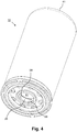
- the device 100 has a cup-shaped housing 10 with therein arranged as an annular coalescer formed filter element, for example a so-called spin-on filter.
- an annular coalescer formed filter element for example a so-called spin-on filter.
- the filter element glass fiber 210 which is wound several times annular and limited by two end plates 30, 40. is.
- fleece 220 is disposed inside the glass fiber winding.
- the main body of the cup-shaped housing is preferably formed by an example deep-drawn housing pot 11 with a housing bottom 41, which has an open end face.
- the cup-shaped housing 10 has a housing cover 20. This housing cover 20 has for discharging the filtered clean air an opening 21 (see. FIG. 4 ) on.
- This opening 21 is arranged centrally in the housing cover 20.
- the area surrounding the opening of the housing cover 20 is substantially cylindrical, in particular circular cylindrical, for example, as an annular collar of the housing cover formed.
- a nipple 50 extending through the housing cover 20 in the direction of the longitudinal axis of the cup-shaped housing 10 is accommodated.
- the housing cover is detachably connectable to the nipple 50.
- the detachably connectable to the nipple 50 region 26 of the housing cover 20 is formed such that in the connected state of the housing cover 20 with the nipple 50 between the housing cover 20 and nipple 50 at least one liquid drain 28, such as an oil passage or connecting channel, for discharging the separated liquid from the interior 70 of the cup-shaped housing 10 is arranged.
- the liquid drain 28 by at least one in the axial direction of an inner space 70 of the cup-shaped housing 10 facing inner region of the nipple 50 'to a remote from the interior 70 of the cup-shaped housing 10 outer region of the nipple 50' extending groove or channel-like recess 28 of the nipple 50 ' may be formed.
- This groove 28 'arranged on the nipple 28 may be arranged, for example in an external thread of the nipple 50'.
- the liquid drain 28 can therefore be formed, for example, by a drain groove (not shown) in the housing cover 20 and / or in a thread of the nipple 50 '(not shown).
- the liquid drain be performed by at least one through hole 280 extending in the axial direction of the inner space 70 of the cup-shaped housing 10 facing inside 24 of the housing cover 20 facing away from the interior 70 of the cup-shaped housing 10 outside 25 of the housing cover 20 through the housing cover 20th extends.
- the nipple 50, 50 ' can also be connected to the housing cover 20 by means of a bayonet connection.
- the liquid drain 28 enables a permanent emptying between the nipple and the housing cover in the completely connected, for example bolted, state of the nipple 50, 50 'and the housing cover 20.
- the liquid outlet 28 is assigned to the clean air side of the cup-shaped housing 10.
- the liquid collects in the liquid collecting space 230, which is preferably embodied as a depression in the front-side, open end disk 40 of the filter element 210, 220 and can be formed at least partially by the annular bead 42.
- the liquid outlet 28 is connected to a discharge channel 86 of the connection head 80.
- the housing cover 20 has at least one eccentrically arranged unfiltered air inlet 22, 23.
- the flow of air is in Fig. 1 represented by dashed arrows.
- the arrows are drawn only in the left half of the picture.
- a seal 61 is provided, which can be applied and compressed in a sealing manner axially relative to the connection head or base 80. This is usually designed as a ring seal and attached to the housing cover 20.
- a collar 54 extending in the radial direction is arranged on the nipple 50, 50 '. Between the housing cover and collar, a seal 60 extends and seals the unfiltered air inlet 22, 23 from the liquid outlet 28.
- the seal also directly between the housing cover 20 and connection head or base 80 done.
- the seal 60 "'can thus also extend between the housing cover 20 and the connection head 80.
- the nipple be formed without radial collar.
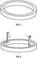
- the seal 60 may, as in Fig. 1 shown, in the direction of the longitudinal axis of the cup-shaped housing 10 extending fixing lug for clamping the sealing surface 60 on the housing cover.
- the fixing lug 62 is arranged in a liquid outlet 28.
- the seal 60 also be a conventional ring seal.
- the cup-shaped housing 10 for sealing between liquid outlet 28 and unfiltered air inlet 22 further comprises at least one seal 64 arranged on the inside 24 of the housing cover 20 facing the interior 70 of the cup-shaped housing 10. Specifically, this further seal 64 in the present embodiment between an annular bead 42 of an end-face end plate 40 of the cup-shaped housing and the inside 24 of the housing cover 20, respectively.
- the clean air outlet 52 extends into the filter element 210, 220, in particular approximately up to the middle of the filter element 210, 220.
- connection head 80 for connecting the device 100 to a component of an engine.
- the nipple 50 or 50' also consists of only one part instead of, as usual, from the nipple and an inserted additional tube to provide an annular gap for the liquid flow.
- no sealing seat and O-ring in the associated spin-on filter this results in a further cost advantage.
Landscapes
- Chemical & Material Sciences (AREA)
- Chemical Kinetics & Catalysis (AREA)
- Physics & Mathematics (AREA)
- Geometry (AREA)
- Filtering Of Dispersed Particles In Gases (AREA)
- Separation By Low-Temperature Treatments (AREA)
- Engineering & Computer Science (AREA)
- Mechanical Engineering (AREA)
Description
Die vorliegende Erfindung betrifft eine Vorrichtung zum Abscheiden von Flüssigkeit aus Luft gemäß dem Oberbegriff des Anspruchs 1. Die Erfindung betrifft des Weiteren ein becherförmiges Gehäuse nach dem Anspruch 16.The present invention relates to a device for separating liquid from air according to the preamble of claim 1. The invention further relates to a cup-shaped housing according to claim 16.
Aus der Druckschrift
Des Weiteren sind beispielsweise aus den Druckschriften
Aus der Druckschrift
Der Erfindung liegt die Aufgabe zugrunde, ein becherförmiges Gehäuse gemäß der vorstehend genannten Art, eine Vorrichtung zum Abscheiden von Flüssigkeit aus Luft gemäß der vorstehend genannten Art sowie ein Verfahren zur Montage eines becherförmigen Gehäuses gemäß der vorstehend genannten Art so weiterzubilden, dass zum Abführen der gefilterten Reinluft möglichst wenig Energie benötigt wird.The invention has the object of providing a cup-shaped housing according to the aforementioned type, a device for separating liquid from air according to the aforementioned type and a method for mounting a cup-shaped housing according to the aforementioned type such that for discharging the filtered Clean air as little energy is needed.
Diese Aufgabe wird durch ein becherförmiges Gehäuse mit den im Anspruch 16 angegebenen Merkmalen sowie durch eine Vorrichtung mit den im Anspruch 1 angegebenen Merkmalen gelöst. Vorteilhafte Ausgestaltungen und zweckmäßige Weiterbildungen der vorliegenden Erfindung sind in den jeweiligen Unteransprüchen gekennzeichnet.This object is achieved by a cup-shaped housing having the features specified in claim 16 and by a device having the features specified in claim 1. Advantageous embodiments and expedient developments of the present invention are characterized in the respective subclaims.
Mithin basiert die Erfindung darauf, dass zum Abdichten zwischen der Rohluftseite und der Reinluftseite, insbesondere des rohluftseitigen Rohlufteinlasses von der reinluftseitigen Öffnung, an der vom Innenraum des becherförmigen Gehäuses abgewandten Außenseite des Gehäusedeckels zumindest bereichsweise mindestens eine Dichtfläche angeordnet ist. Das erfindungsgemäße becherförmige Gehäuse und die erfindungsgemäße Vorrichtung weisen also zusätzlich eine an der Außenseite des Gehäusedeckels des becherförmigen Gehäuses angeordnete Dichtfläche auf.Consequently, the invention is based on the fact that, at least in some areas, at least in some areas at least one sealing surface is arranged on the outside of the housing cover facing away from the interior of the cup-shaped housing for sealing between the unfiltered air side and the clean air side, in particular of the roughness air side unfiltered air inlet. The cup-shaped housing according to the invention and the device according to the invention therefore additionally have a sealing surface arranged on the outside of the housing cover of the cup-shaped housing.
Dies hat den Vorteil, dass im Gegensatz zum Stand der Technik der Flüssigkeitsablauf zum Ableiten der abgeschiedenen Flüssigkeit aus dem Innenraum des becherförmigen Gehäuses im Bereich der reinluftseitigen Öffnung des Gehäusedeckels erfolgen kann. Somit kann eine Luftentölbox mit platzsparendem Auslauf bereitgestellt werden. Im Gegensatz zum Stand der Technik muss also der Flüssigkeitsablauf nicht innerhalb eines mit dem becherförmigen Gehäuses verbundenen Nippels erfolgen und muss zum Bereitstellen des Flüssigkeitsablaufs kein Rohrelement im Nippel angeordnet werden.This has the advantage that, in contrast to the prior art, the liquid drain for discharging the separated liquid from the interior of the cup-shaped housing in the region of the clean air side opening of the housing cover can be done. Thus, a Luftentölbox be provided with space-saving outlet. In contrast to the prior art, therefore, the liquid drain does not have to take place within a nipple connected to the cup-shaped housing and has to be provided the liquid drain no pipe element can be arranged in the nipple.
Erfindungsgemäß ist die reinluftseitige Öffnung zum Aufnehmen eines sich durch den Gehäusedeckel in Richtung der Längsachse des becherförmigen Gehäuses erstreckenden Nippels ausgebildet. Ferner weist der Gehäusedeckel im Bereich der reinluftseitigen Öffnung zum lösbaren Verbinden des Gehäusedeckels mit dem Nippel mindestens einen mit dem Nippel lösbar verbindbaren Bereich auf, wobei die Dichtfläche derart am Gehäusedeckel angeordnet ist, dass im verbundenen Zustand des Gehäusedeckels mit dem Nippel die Dichtfläche zwischen Gehäusedeckel und Nippel angeordnet ist und den rohluftseitigen Rohlufteinlass von der reinluftseitigen Öffnung abdichtet. Alternativ kann die Dichtfläche auch derart am Gehäusedeckel angeordnet sein, dass im verbundenen Zustand des Gehäusedeckels mit dem Nippel die Dichtfläche zwischen Gehäusedeckel und einem mit dem Nippel verbundenen Anschlusskopf angeordnet ist und den rohluftseitigen Rohlufteinlass von der reinluftseitigen Öffnung abdichtet. Bei dem erfindungsgemäßen becherförmigen Gehäuse ist der Flüssigkeitsablauf reinluftseitig angeordnet und die Dichtfläche derart am Gehäusedeckel angeordnet, dass sie den Rohlufteinlass vom Flüssigkeitsablauf abdichtet.
Zum Ableiten der abgeschiedenen Flüssigkeit aus dem Innenraum des becherförmigen Gehäuses sind bei der vorliegenden Erfindung der Nippel und/oder das becherförmige Gehäuse, insbesondere der mit dem Nippel lösbar verbindbare Bereich des Gehäusedeckels, derart ausgebildet, dass im verbundenen Zustand des becherförmigen Gehäuses, insbesondere des Gehäusedeckels, mit dem Nippel zwischen dem becherförmigen Gehäuse, insbesondere dem Gehäusedeckel, und dem Nippel mindestens ein Flüssigkeitsablauf angeordnet ist. Die abgeschiedene Flüssigkeit kann also aus dem Innenraum des becherförmigen Gehäuses im verbundenen Zustand des Gehäusedeckels mit dem Nippel abgeleitet werden, ohne dass hierfür in den Nippel ein zusätzliches Rohrelement eingesteckt werden muss. So wird der Innendurchmesser des Nippels nicht durch ein eingestecktes zusätzliches Rohrelement eingeengt.According to the invention, the clean air-side opening is designed to receive a nipple extending through the housing cover in the direction of the longitudinal axis of the cup-shaped housing. Furthermore, the housing cover in the region of the clean air side opening for releasably connecting the housing cover with the nipple at least one releasably connectable to the nipple area, wherein the sealing surface is arranged on the housing cover, that in the connected state of the housing cover with the nipple, the sealing surface between the housing cover and Nipple is arranged and seals the raw air-side unfiltered air inlet of the clean air side opening. Alternatively, the sealing surface may also be arranged on the housing cover such that in the connected state of the housing cover with the nipple, the sealing surface between the housing cover and a connection head connected to the nipple is arranged and seals the raw air side unfiltered air inlet from the clean air side opening. In the case of the cup-shaped housing according to the invention, the liquid outlet is arranged on the clean air side and the sealing surface is arranged on the housing cover such that it seals off the unfiltered air inlet from the liquid outlet.
For deriving the separated liquid from the interior of the cup-shaped housing in the present invention, the nipple and / or the cup-shaped housing, in particular the releasably connectable to the nipple portion of the housing cover, formed such that in the connected state of the cup-shaped housing, in particular the housing cover , with the nipple between the cup-shaped housing, in particular the housing cover, and the nipple at least one liquid outlet is arranged. The separated liquid can therefore be discharged from the interior of the cup-shaped housing in the connected state of the housing cover with the nipple, without the need for an additional pipe element must be inserted into the nipple. Thus, the inner diameter of the nipple is not restricted by an inserted additional pipe element.
Stattdessen kann der Nippel im Anschluss an den mit dem becherförmigen Gehäuse lösbar verbindbaren Bereich des Nippels ein zylinderförmiges Rohrelement aufweisen, das zum Trennen der abgeschiedenen Flüssigkeit von der gereinigten Luft ausgebildet ist und einen Reinluftauslass zum Ableiten der gefilterten Reinluft aus dem becherförmigen Gehäuse bildet. Im Gegensatz zum Stand der Technik kann also der Nippel selbst als Reinluftauslass ausgebildet sein und im Wesentlichen denselben Innendurchmesser aufweisen, wie der mit dem becherförmigen Gehäuse lösbar verbindbare Bereich des Nippels. Im Vergleich zum Stand der Technik, bei dem der Reinluftauslass durch ein in den Nippel eingestecktes Rohrelement gebildet ist, ist bei der vorliegenden Erfindung der Innendurchmesser für den Reinluftauslass wesentlich größer, wodurch sich ein geringerer Differenzdruck ergibt und weniger Energie zum Abführen der gefilterten Reinluft benötigt wird.Instead, the nipple, following the region of the nipple which can be detachably connected to the cup-shaped housing, can have a cylindrical tubular element which is designed to separate the separated liquid from the purified air and a clean air outlet for discharging the filtered clean air from the cup-shaped housing forms. In contrast to the prior art, therefore, the nipple itself may be formed as a clean air outlet and have substantially the same inner diameter as the releasably connectable to the cup-shaped housing portion of the nipple. Compared with the prior art in which the clean air outlet is formed by a pipe element inserted into the nipple, in the present invention the internal diameter for the clean air outlet is substantially larger, resulting in a lower differential pressure and less energy needed to remove the filtered clean air ,
Vorteilhafterweise erstreckt sich der Flüssigkeitsablauf in Richtung der Längsachse des becherförmigen Gehäuses, also axial, von der dem Innenraum des becherförmigen Gehäuses zugewandten Innenseite des Gehäusedeckels zur vom Innenraum des becherförmigen Gehäuses abgewandten Außenseite des Gehäusedeckels. Vorteilhafterweise ist der Flüssigkeitsablauf radial zwischen dem üblicherweise mittig angeordneten Reinluftauslass und dem außermittig angeordneten Rohlufteinlass angeordnet. Dabei können beispielsweise der Rohlufteinlass und/oder der Flüssigkeitsablauf durch mehrere kreisförmig regelmäßig oder unregelmäßig um den Reinluftauslass angeordnete Öffnungen oder Ausnehmungen gebildet sein.Advantageously, the liquid drain extends in the direction of the longitudinal axis of the cup-shaped housing, ie axially, from the inside of the housing cover facing the interior of the cup-shaped housing to the outside of the housing cover facing away from the interior of the cup-shaped housing. Advantageously, the liquid outlet is arranged radially between the usually centrally arranged clean air outlet and the off-center unfiltered air inlet. In this case, for example, the unfiltered air inlet and / or the liquid outlet can be formed by a plurality of circular openings or recesses arranged regularly or irregularly around the clean air outlet.
Zum lösbaren Verbinden des becherförmigen Gehäuses mit dem Nippel können diese beispielsweise mittels einer Schraubverbindung oder mittels einer Bajonettverbindung miteinander verbunden werden. Der mit dem Nippel lösbar verbindbare Bereich des Gehäusedeckels kann also beispielsweise ein Innengewinde des Gehäusedeckels sein, das zum lösbaren Verbinden des becherförmigen Gehäuses mit dem Nippel mit einem Außengewinde des Nippels verschraubbar ist. Vorteilhafterweise ist bei dieser Ausführungsform also ein mit dem Gehäusedeckel lösbar verbindbarer Bereich des Nippels als Außengewinde ausgebildet.For releasable connection of the cup-shaped housing with the nipple they can be connected to each other, for example by means of a screw or by means of a bayonet connection. The region of the housing cover which can be detachably connected to the nipple can thus be, for example, an internal thread of the housing cover which can be screwed to the nipple for releasably connecting the cup-shaped housing to an external thread of the nipple. Advantageously, in this embodiment, therefore, a detachably connectable to the housing cover portion of the nipple is formed as an external thread.
Der Flüssigkeitsablauf kann durch eine Nut gebildet sein, die am mit dem Nippel lösbar verbindbaren Bereich des Gehäusedeckels, beispielsweise in dem Innengewinde des Gehäusedeckels, und /oder an dem mit dem Gehäusedeckel lösbar verbindbaren Bereich des Nippels, beispielsweise in dem Außengewinde des Nippels, angeordnet ist.The liquid drainage can be formed by a groove which is arranged on the region of the housing cover detachably connectable to the nipple, for example in the internal thread of the housing cover, and / or on the region of the nipple detachably connectable to the housing cover, for example in the external thread of the nipple ,
Dabei kann der Flüssigkeitsablauf eine geradlinig ausgebildete und sich in Richtung der Längsachse des becherförmigen Gehäuses erstreckende Nut sein.In this case, the liquid drain can be a rectilinear groove extending in the direction of the longitudinal axis of the cup-shaped housing.
Um einen vergrößerten Ablaufquerschnitt bereitzustellen, können mehrere der in den beiden vorherigen Absätzen beschriebenen Nuten regelmäßig oder unregelmäßig kreisförmig umlaufend angeordnet werden.In order to provide an enlarged flow cross section, a plurality of the grooves described in the two preceding paragraphs can be arranged regularly or irregularly circulating circular.
Alternativ kann der Flüssigkeitsablauf sich auch spiralartig von der dem Innenraum des becherförmigen Gehäuses zugewandten Innenseite des Gehäusedeckels zur vom Innenraum des becherförmigen Gehäuses abgewandten Außenseite des Gehäusedeckels erstrecken. Beispielsweise kann der Flüssigkeitsablauf durch eine vergrößerte Gewindetiefe des Innengewindes des Gehäusedeckels und/oder durch eine vergrößerte Gewindetiefe des Außengewindes des Nippels gebildet sein.Alternatively, the liquid drain can also extend in a spiral manner from the inside of the housing cover facing the interior of the cup-shaped housing to the outside of the housing cover facing away from the interior of the cup-shaped housing. For example, the liquid drain can be formed by an enlarged thread depth of the internal thread of the housing cover and / or by an enlarged thread depth of the external thread of the nipple.
Alternativ ist der Flüssigkeitsablauf durch mindestens eine kanalartige Ausnehmung oder Bohrung im Gehäusedeckel gebildet, die sich bevorzugt axial erstreckt und weiter bevorzugt radial zwischen der mittig im Gehäusedeckel angeordneten reinluftseitigen Öffnung und mindestens einem außermittig im Gehäusedeckel angeordneten rohluftseitigen Rohlufteinlass angeordnet ist.Alternatively, the liquid outlet is formed by at least one channel-like recess or bore in the housing cover, which preferably extends axially and more preferably radially between the centrally disposed in the housing cover clean air side opening and at least one eccentrically arranged in the housing cover raw air side Rohlufteinlass is arranged.
In einer bevorzugten Ausführungsform ist die Dichtfläche derart ringförmig zwischen Rohlufteinlass und Flüssigkeitsablauf am Gehäusedeckel angeordnet, dass sie den Rohlufteinlass vom Flüssigkeitsablauf abdichtet. So ergeben sich vorteilhaft zwei Druckniveaus, ein rohluftseitiges Druckniveau stromauf eines im becherförmigen Gehäuse angeordneten Filterelements und ein reinluftseitiges Druckniveau stromab des Filterelements auf der Seite des Reinluftraums, wobei Reinluftauslass und reinluftseitige Öffnung und Flüssigkeitsablauf in Verbindung mit dem Reinluftraum stehen und damit auch auf der Seite des reinluftseitigen Druckniveaus angeordnet sind.In a preferred embodiment, the sealing surface is arranged in an annular manner between the unfiltered air inlet and the liquid outlet on the housing cover such that it seals off the unfiltered air inlet from the liquid outlet. Thus, two pressure levels, a raw air-side pressure level upstream of a filter element arranged in the cup-shaped housing and a clean air-side pressure level downstream of the filter element on the side of the clean air space, wherein clean air outlet and clean air side opening and liquid drain are in communication with the clean air space and thus also on the side of the clean air are arranged on the clean air side pressure levels.
Zum Abscheiden von Flüssigkeit aus Luft ist im becherförmigen Gehäuse mindestens ein als ringförmiger Coalescer ausgebildetes Filterelement angeordnet, das den Innenraum des becherförmigen Gehäuses in einen Rohluftraum und einen Reinluftraum unterteilt. Das Filterelement kann ein austauschbares Filterelement sein. Alternativ kann das Filterelement im Wartungsfall komplett mit dem becherförmigen Gehäuse ersetzt werden. Das Filterelement kann beispielsweise ein Filterelement eines sogenannten Spin-on-Filters sein. Das Filterelement kann mindestens ein Filtermedium aufweisen. Als Filtermedien können Glasfaser, etwa mehrfachgewickelte Glasfaser und/oder Vlies eingesetzt werden,For separating liquid from air in the cup-shaped housing at least one designed as an annular coalescer filter element is arranged, which divides the interior of the cup-shaped housing into a raw air space and a clean air space. The filter element may be an exchangeable filter element. Alternatively, the filter element can be completely replaced with the cup-shaped housing in case of maintenance. The filter element may for example be a filter element of a so-called spin-on filter be. The filter element may have at least one filter medium. As filter media glass fiber, such as multi-wound glass fiber and / or nonwoven can be used,
In einer bevorzugten Ausführungsform weist das Filterelement an einem dem Gehäusedeckel zugewandten Ende, insbesondere an der dort angeordneten Endscheibe, einen Flüssigkeitssammelraum auf, der mit dem Flüssigkeitsablauf verbindbar ist. Aus dem Flüssigkeitssammelraum kann die abgeschiedene Flüssigkeit durch den Flüssigkeitsablauf in den Sumpf der Kraftmaschine, beispielsweise des Kompressors, zurückgeführt werden.In a preferred embodiment, the filter element at a end facing the housing cover, in particular at the end disk arranged there, on a liquid collecting space, which is connectable to the liquid drain. From the liquid collecting space, the separated liquid can be recirculated through the liquid outlet into the sump of the engine, for example the compressor.
Das Filterelement kann außerdem verwendet werden für Flüssigkeiten jedweder Art einer Kraftmaschine, insbesondere eines Kompressors, beispielsweise eines Druckluftkompressors, wie beispielsweise Öle, Kraftstoffe, Hydraulikflüssigkeiten oder auch Kühlmittel.The filter element can also be used for liquids of any type of engine, in particular a compressor, for example an air compressor, such as oils, fuels, hydraulic fluids or coolant.
Zum Zuführen von Rohluft in das becherförmige Gehäuse weist der Gehäusedeckel mindestens einen rohluftseitigen Rohlufteinlass auf. Dieser Rohlufteinlass ist außermittig im Gehäusedeckel angeordnet. Bevorzugt ist zur Abdichtung des Rohlufteinlasses gegenüber der Umgebung eine äußere Dichtfläche oder Dichtung vorgesehen. Diese ist bevorzugt als axial gegenüber dem Anschlusskopf verpressbarer Dichtring ausgeführt und am Gehäusedeckel weiter bevorzugt den oder die Rohlufteinlässe umgebend angeordnet. Der Rohlufteinlass kann sich in axialer Richtung in einen mit dem Nippel lösbar verbundenen Anschlusskopf erstrecken. Der mit dem Nippel lösbar verbindbare Anschlusskopf kann ein separater Anschlussflansch sein oder auch direkt aus einer Komponente eines Druckluftkompressors, beispielsweise dem Gehäuse, gebildet sein.For supplying raw air into the cup-shaped housing, the housing cover has at least one raw air-side unfiltered air inlet. This unfiltered air intake is arranged eccentrically in the housing cover. Preferably, an outer sealing surface or seal is provided to seal the unfiltered air inlet from the environment. This is preferably designed as a sealing ring which can be pressed axially relative to the connection head and further preferably surrounds or surrounds the unfiltered air inlets on the housing cover. The unfiltered air inlet can extend in the axial direction into a connection head releasably connected to the nipple. The detachably connectable to the nipple connection head may be a separate connection flange or directly from a component of an air compressor, such as the housing may be formed.
Wie vorstehend beschrieben, erfolgt das Ableiten der Reinluft durch die Öffnung des Gehäusedeckels. Der Reinluftauslass zum Ableiten der gefilterten Reinluft aus dem becherförmigen Gehäuse ist durch den Nippel gebildet. Der Nippel ist vorzugsweise zentral im Gehäusedeckel angeordnet. Der Flüssigkeitsablauf ist der Reinluftseite der Vorrichtung zugeordnet. Zum Abdichten zwischen der Rohluftseite und der Reinluftseite, insbesondere zum Abdichten zwischen Flüssigkeitsablauf und Rohlufteinlass, ist der Gehäusedeckel an seiner vom Innenraum des becherförmigen Gehäuses abgewandten Außenseite zumindest bereichsweise als Dichtfläche ausgebildet. Unabhängig hiervon oder in Verbindung hiermit kann zum Abdichten zwischen der Rohluftseite und der Reinluftseite der Vorrichtung an der vom Innenraum des becherförmigen Gehäuses abgewandten Außenseite des Gehäusedeckels zumindest bereichsweise mindestens eine Dichtfläche angeordnet sein.As described above, the discharge of the clean air through the opening of the housing cover takes place. The clean air outlet for draining the filtered clean air from the cup-shaped housing is formed by the nipple. The nipple is preferably arranged centrally in the housing cover. The liquid drain is associated with the clean air side of the device. For sealing between the unfiltered air side and the clean air side, in particular for sealing between the liquid outlet and the unfiltered air inlet, the housing cover is formed on its side facing away from the interior of the cup-shaped housing outside at least partially as a sealing surface. Independently hereof or in conjunction therewith, at least partially sealing surface may be arranged at least partially for sealing between the unfiltered air side and the clean air side of the device at the outside of the housing cover facing away from the interior of the cup-shaped housing.
Gemäß einer vorteilhaften Ausführungsform der Erfindung kann die Dichtfläche durch eine Fläche des Gehäusedeckels gebildet sein. In diesem Fall ist also der Gehäusedeckel selbst an seiner vom Innenraum des becherförmigen Gehäuses abgewandten Außenseite zumindest bereichsweise als Dichtfläche ausgebildet. Eine aus dem Gehäusedeckel gebildete Dichtfläche ist vorteilhaft, da sie nicht verrutschen oder verloren gehen kann.According to an advantageous embodiment of the invention, the sealing surface may be formed by a surface of the housing cover. In this case, therefore, the housing cover itself is at least partially formed as a sealing surface on its outer side facing away from the interior of the cup-shaped housing outside. A sealing surface formed from the housing cover is advantageous because it can not slip or get lost.
Beispielsweise kann die Dichtfläche durch eine Metallfläche des Gehäusedeckels gebildet sein. Dies hat den Vorteil, dass die Dichtfläche temperaturunempfindlich und langlebig ist. Diese Dichtfläche kann derart mit einer Metallfläche des Nippels oder einer Metallfläche eines Sockels oder eines Anschlusskopfs zusammenwirken, dass eine Abdichtung zwischen der Rohluftseite und der Reinluftseite erfolgt. Es kann also auch ohne extra Dichtung gedichtet werden, indem zwei Metallflächen dichtend miteinander in Kontakt stehen. Insbesondere kann der Gehäusedeckel, beispielsweise eine Gewindeplatte des Gehäusedeckels, dichtend auf dem Nippel aufliegen. Ergänzend oder alternativ hierzu kann der Gehäusedeckel, beispielsweise eine Gewindeplatte des Gehäusedeckels, dichtend auf dem Anschlusskopf, beispielsweise einem Filterkopf, aufliegen.For example, the sealing surface may be formed by a metal surface of the housing cover. This has the advantage that the sealing surface is temperature insensitive and durable. This sealing surface can cooperate with a metal surface of the nipple or a metal surface of a base or of a connection head in such a way that a sealing takes place between the dirty air side and the clean air side. It can therefore be sealed without extra seal by two metal surfaces sealingly in contact with each other. In particular, the housing cover, for example, a threaded plate of the housing cover, sealingly rest on the nipple. Additionally or alternatively, the housing cover, for example, a threaded plate of the housing cover, sealing on the connection head, such as a filter head, rest.
Alternativ oder ergänzend zu einer aus einem Bereich des Gehäusedeckels gebildeten Dichtfläche kann die Dichtfläche durch mindestens eine am Gehäusedeckel angeordnete Dichtung, beispielsweise durch eine Kunststoffdichtung gebildet sein. Zur Befestigung am Gehäusedeckel kann die Kunststoffdichtung mittels mindestens eines Spritzverfahrens an den Gehäusedeckel und/oder an den Nippel angespritzt werden. Alternativ kann die Dichtfläche auch an den Gehäusedeckel und/oder an den Nippel angeklipst, angeklemmt oder angeklebt werden.As an alternative or in addition to a sealing surface formed from a region of the housing cover, the sealing surface may be formed by at least one seal arranged on the housing cover, for example by a plastic seal. For attachment to the housing cover, the plastic seal can be injected by means of at least one injection molding process to the housing cover and / or to the nipple. Alternatively, the sealing surface can also be clipped, clamped or glued to the housing cover and / or to the nipple.
Zum Anklipsen oder Anklemmen an den Gehäusedeckel kann die Dichtfläche eine Dichtung sein mit mindestens einem sich in Richtung der Längsachse des becherförmigen Gehäuses erstreckenden Fixierelement. Ist der mit dem Nippel lösbar verbindbare Bereich des Gehäusedeckels derart ausgebildet, dass im verbundenen Zustand des Gehäusedeckels mit dem Nippel zwischen Gehäusedeckel und Nippel mehrere Flüssigkeitsabläufe zum Ableiten der abgeschiedenen Flüssigkeit aus dem Innenraum des becherförmigen Gehäuses angeordnet sind, so kann das Fixierelement dazu ausgebildet sein derart am Gehäusedeckel angeordnet zu werden, dass es sich durch einen der Flüssigkeitsabläufe erstreckt und auf diese Weise die Dichtung am Gehäusedeckel fixiert,For clipping or clamping on the housing cover, the sealing surface may be a seal with at least one fixing element extending in the direction of the longitudinal axis of the cup-shaped housing. If the region of the housing cover which can be detachably connected to the nipple is designed in such a way that that in the connected state of the housing cover with the nipple between the housing cover and nipple more liquid drains for draining the separated liquid from the interior of the cup-shaped housing are arranged, the fixing element may be designed to be arranged on the housing cover, that it is by one of the liquid drains extends and fixes the seal on the housing cover in this way,
Die Dichtfläche kann ringförmig oder zylinderförmig ausgebildet sein, beispielsweise eine ringförmige oder zylinderförmige Dichtung sein.The sealing surface may be annular or cylindrical, for example, be an annular or cylindrical seal.
Die Dichtfläche ist vorteilhafterweise zum Abdichten zwischen Gehäusedeckel und Nippel ausgebildet. Die Dichtfläche oder Dichtung liegt dabei in axialer Richtung dichtend an dem Nippel oder an einer korrespondierenden Fläche des Anschlusskopfes an. Beispielsweise kann die Dichtfläche in axialer Richtung zwischen dem becherförmigem Gehäuse und einem sich radial, also sich senkrecht zur Längsrichtung (axialen Richtung) des becherförmigen Gehäuses erstreckenden Vorsprung, beispielsweise einem Kragen, des Nippels angeordnet sein. Dieser radiale Vorsprung liegt vorteilhafterweise axial abdichtend am Anschlusskopf der Kraftmaschine an, wenn der Nippel mit dem Anschlusskopf verbunden ist. Der Flüssigkeitsablauf kann sich in der axialen Verlängerung des Verbindungsbereichs des Gehäusedeckels mit dem Nippel durch den Kragen des Nippels erstrecken. Der Rohlufteinlass ist vorzugsweise an der vom Nippel abgewandten Außenseite des Kragens angeordnet. Dieser Rohlufteinlass kann sich in axialer Richtung in den Anschlusskopf der Kraftmaschine erstrecken. Zum Abdichten zwischen der Rohluftseite und der Reinluftseite wirkt bei diesem Ausführungsbeispiel die Dichtfläche im verbundenen Zustand des becherförmigen Gehäuses, insbesondere des Gehäusedeckels, mit dem Nippel derart mit dem Kragen des Nippels zusammen, dass eine Abdichtung zwischen dem Rohlufteinlass und dem Flüssigkeitsablauf erfolgt,The sealing surface is advantageously designed for sealing between the housing cover and nipple. The sealing surface or seal is in the axial direction sealingly against the nipple or on a corresponding surface of the connection head. For example, the sealing surface in the axial direction between the cup-shaped housing and a radially, so perpendicular to the longitudinal direction (axial direction) of the cup-shaped housing extending projection, such as a collar, the nipple be arranged. This radial projection is advantageously axially sealing on the connection head of the engine when the nipple is connected to the connection head. The liquid drain may extend in the axial extension of the connecting portion of the housing cover with the nipple through the collar of the nipple. The unfiltered air inlet is preferably arranged on the side of the collar facing away from the nipple. This unfiltered air inlet can extend in the axial direction into the connection head of the engine. For sealing between the raw air side and the clean air side acts in this embodiment, the sealing surface in the connected state of the cup-shaped housing, in particular the housing cover, with the nipple so with the collar of the nipple so that a seal between the unfiltered air inlet and the liquid flow takes place
Wie bereits vorstehend erörtert, gibt es verschiedene Möglichkeiten, die Lehre der vorliegenden Erfindung in vorteilhafter Weise auszugestalten und weiterzubilden. Hierzu wird einerseits auf die dem Anspruch 1 sowie dem Anspruch 16 nachgeordneten Ansprüche verwiesen, andererseits werden weitere Ausgestaltungen, Merkmale und Vorteile der vorliegenden Erfindung nachstehend unter anderem anhand der durch die
Es zeigt:
-
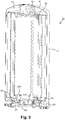
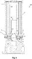
Fig. 1 in schematischer Schnittdarstellung ein erstes Ausführungsbeispiel einer Vorrichtung gemäß der vorliegenden Erfindung mit einem becherförmigen Gehäuse gemäß der vorliegenden Erfindung, das nach dem Verfahren gemäß der vorliegenden Erfindung montiert ist; -
Fig. 2 in schematischer Schnittdarstellung das becherförmige Gehäuse der Vorrichtung ausFigur 1 mit einem zweiten Ausführungsbeispiel einer Dichtung; -
Fig. 3 in perspektivischer Schnittdarstellung das becherförmige Gehäuse der Vorrichtung ausFigur 2 ; -
Fig. 4 in isometrischer Darstellung das becherförmige Gehäuse der Vorrichtung ausFigur 1 ; -
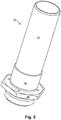
Fig. 5 in isometrischer Darstellung den Nippel der Vorrichtung aus Figur 1; -
Fig. 6 in isometrischer Darstellung ein zweites Ausführungsbeispiel eines Nippels für eine Vorrichtung gemäß der vorliegenden Erfindung; -
Fig. 7 in isometrischer Darstellung eine Detaildarstellung der Dichtung des becherförmigen Gehäuses ausFigur 2 undFigur 3 ; -
Fig. 8 in isometrischer Darstellung die Dichtung der Vorrichtung aus Figur 1; -
Fig. 9 in schematischer Schnittdarstellung die Vorrichtung ausFigur 1 mit einem Ausführungsbeispiel einer Dichtung; und -
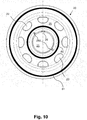
Fig. 10 eine Draufsicht einer alternativen Ausführung des Gehäusedeckels des becherförmigen Gehäuses ausFigur 3 .
It shows:
-
Fig. 1 a schematic sectional view of a first embodiment of a device according to the present invention with a cup-shaped housing according to the present invention, which is mounted according to the method according to the present invention; -
Fig. 2 in a schematic sectional view of the cup-shaped housing of the deviceFIG. 1 with a second embodiment of a seal; -
Fig. 3 in a perspective sectional view of the cup-shaped housing of the deviceFIG. 2 ; -
Fig. 4 in isometric view of the cup-shaped housing of the deviceFIG. 1 ; -
Fig. 5 in an isometric view of the nipple of the device of Figure 1; -
Fig. 6 an isometric view of a second embodiment of a nipple for a device according to the present invention; -
Fig. 7 in isometric view a detailed representation of the seal of the cup-shaped housingFIG. 2 andFIG. 3 ; -
Fig. 8 in an isometric view of the seal of the device of Figure 1; -
Fig. 9 in a schematic sectional view of the deviceFIG. 1 with an embodiment of a seal; and -
Fig. 10 a plan view of an alternative embodiment of the housing cover of the cup-shaped housingFIG. 3 ,
Gleiche oder ähnliche Ausgestaltungen, Elemente oder Merkmale sind in den
Zur Vermeidung überflüssiger Wiederholungen beziehen sich die nachfolgenden Erläuterungen hinsichtlich der Ausgestaltungen, Merkmale und Vorteile der vorliegenden Erfindung (soweit nicht anderweitig angegeben) sowohl auf das in den
Im anhand der
Der Grundkörper des becherförmigen Gehäuses wird bevorzugt durch einen beispielsweise tiefgezogenen Gehäusetopf 11 mit einem Gehäuseboden 41 gebildet, der eine offene Stirnseite aufweist. Zum Verschließen seiner offenen Stirnseite weist das becherförmige Gehäuse 10 einen Gehäusedeckel 20 auf. Dieser Gehäusedeckel 20 weist zum Abführen der gefilterten Reinluft eine Öffnung 21 (vgl.
Diese Öffnung 21 ist mittig im Gehäusedeckel 20 angeordnet.This
Der die Öffnung umgebende Bereich des Gehäusedeckels 20 ist im Wesentlichen zylinderförmig, insbesondere kreiszylinderförmig, beispielsweise als Ringkragen des Gehäusedeckels, ausgebildet.The area surrounding the opening of the
In der Öffnung 21 ist ein sich durch den Gehäusedeckel 20 in Richtung der Längsachse des becherförmigen Gehäuses 10 erstreckender Nippel 50 aufgenommen. Der Gehäusedeckel ist lösbar mit dem Nippel 50 verbindbar.In the
Der mit dem Nippel 50 lösbar verbindbare Bereich 26 des Gehäusedeckels 20 ist derart ausgebildet, dass im verbundenen Zustand des Gehäusedeckels 20 mit dem Nippel 50 zwischen Gehäusedeckel 20 und Nippel 50 mindestens ein Flüssigkeitsablauf 28, etwa ein Öldurchlaufkanal bzw. Verbindungskanal, zum Ableiten der abgeschiedenen Flüssigkeit aus dem Innenraum 70 des becherförmigen Gehäuses 10 angeordnet ist.The detachably connectable to the
Wie in den
Alternativ zur Nut 28 im mit dem Nippel 50 verbindbaren Bereich 26 des Gehäusedeckels 20 oder in Ergänzung zur Nut 28 im mit dem Nippel 50 verbindbaren Bereich 26 des Gehäusedeckels 20 kann, wie in
Der Flüssigkeitsablauf 28 kann also beispielsweise durch eine in einem Gewinde (nicht dargestellt) des Gehäusedeckels 20 und/oder in einem Gewinde des (nicht dargestellt) Nippels 50' angeordnete Ablaufnut gebildet werden.The
Alternativ kann auch - wie in
Alternativ zu einer Schraubverbindung kann der Nippel 50, 50' auch mittels einer Bajonettverbindung mit dem Gehäusedeckel 20 verbunden werden.As an alternative to a screw connection, the
Der Flüssigkeitsablauf 28 ermöglich zwischen Nippel und Gehäusedeckel eine permanente Entleerung im vollständig verbundenen, beispielsweise angeschraubten, Zustand von Nippel 50, 50' und Gehäusedeckel 20.The
Der Flüssigkeitsablauf 28 ist der Reinluftseite des becherförmigen Gehäuses 10 zugeordnet. Die Flüssigkeit sammelt sich im Flüssigkeitssammelraum 230, der bevorzugt als Vertiefung in der stirnseitigen, offenen Endscheibe 40 des Filterelements 210, 220 ausgeführt ist und zumindest teilweise durch die Ringsicke 42 gebildet sein kann.The
Zum Ablassen der abgeschiedenen Flüssigkeit ist der Flüssigkeitsablauf 28 mit einem Ablasskanal 86 des Anschlusskopfs 80 verbunden.For discharging the separated liquid, the
Zum Zuführen von Rohluft in das becherförmige Gehäuse 10 weist der Gehäusedeckel 20 mindestens einen außermittig angeordneten Rohlufteinlass 22, 23 auf. Der Strömungsverlauf der Luft ist in
Mit Abstand zum Gehäusedeckel 20 ist am Nippel 50, 50' ein sich in radialer Richtung erstreckender Kragen 54 angeordnet. Zwischen Gehäusedeckel und Kragen erstreckt sich eine Dichtung 60 und dichtet den Rohlufteinlass 22, 23 vom Flüssigkeitsablauf 28 ab.At a distance from the
Alternativ kann, wie in
Die Dichtung 60 kann, wie in
Alternativ kann, wie in den
Neben der an der vom Innenraum 70 des becherförmigen Gehäuses 10 abgewandten Außenseite 26 des Gehäusedeckels 20 angeordneten Dichtfläche 60 weist das becherförmige Gehäuse 10 zur Abdichtung zwischen Flüssigkeitsablauf 28 und Rohlufteinlass 22 des Weiteren mindestens eine an der dem Innenraum 70 des becherförmigen Gehäuses 10 zugewandten Innenseite 24 des Gehäusedeckels 20 angeordnete Dichtung 64 auf. Konkret ist diese weitere Dichtung 64 im vorliegenden Ausführungsbeispiel zwischen einer Ringsicke 42 einer stirnseitigen Endscheibe 40 des becherförmigen Gehäuses und der Innenseite 24 des Gehäusedeckels 20, angeordnet.In addition to the side facing away from the
Zum Ableiten der Reinluft aus dem becherförmigen Gehäuse 10 weist der Nippel 50 bzw. 50' einen zentralen Reinluftauslass 52 auf, der einstückig mit dem Nippel 50 bzw. 50' ausgebildet ist (vgl.
An der vom becherförmigen Gehäuse 10 abgewandten Seite des Nippels ist dieser mit einem Anschlusskopf 80 zum Anschliessen der Vorrichtung 100 an eine Komponente einer Kraftmaschine lösbar verbindbar.At the side facing away from the cup-shaped
Im Unterschied zum Stand der Technik besteht der Nippel 50 bzw. 50'also nur aus einem Teil anstatt, wie üblich, aus dem Nippel und einem eingesteckten zusätzlichen Rohr zur Bereitstellung eines Ringspalts für den Flüssigkeitsablauf. Im Unterschied zum Stand der Technik gibt es bei dem in den
- 1010
-
becherförmiges, insbesondere haubenförmiges oder kreiszylindrisches, Gehäuse der Vorrichtung 100, insbesondere Luftentölbox, beispielsweise Gehäuse eines Spin-on Filterscup-shaped, in particular hood-shaped or circular cylindrical, housing of the
device 100, in particular Luftentölbox, for example housing a spin-on filter - 1111
- Gehäusetopf als Grundkörper des becherförmigen Gehäuses 10Housing pot as the main body of the cup-shaped housing 10th
- 2020
-
Gehäusedeckel, des becherförmigen Gehäuses 10, der den Gehäusetopf 11 verschließtHousing cover, the cup-shaped
housing 10 which closes thehousing pot 11 - 2121
-
Öffnung des Gehäusedeckels 20, insbesondere zentral angeordnete Öffnung des Gehäusedeckels 20Opening of the
housing cover 20, in particular centrally disposed opening of the housing cover 20th - 2222
-
erster Rohlufteinlass, insbesondere erster dezentraler Kanal, des Gehäusedeckels 20 zum Zuströmen von Rohluftfirst unfiltered air inlet, in particular first decentralized channel, of the
housing cover 20 for the inflow of raw air - 2323
-
weiterer Rohlufteinlass, insbesondere weiterer dezentraler Kanal, des Gehäusedeckels 20 zum Zuströmen von Rohluftfurther unfiltered air inlet, in particular further decentralized channel, of the
housing cover 20 for the inflow of raw air - 2424
-
dem Innenraum 70 des becherförmigen Gehäuses 10 zugewandte Innenseite des Gehäusedeckelsthe interior 70 of the cup-shaped
housing 10 facing inside of the housing cover - 2525
-
vom Innenraum 70 des becherförmigen Gehäuses 10 abgewandte Außenseite des Gehäusedeckelsfrom the
interior 70 of the cup-shapedhousing 10 remote from the outside of the housing cover - 2626
-
mit dem Nippel 50 bzw. 50' lösbar verbindbarer Bereich, insbesondere Innengewinde, beispielsweise eines Ringkragens, des Gehäusedeckels 20with the
nipple 50 or 50 'releasably connectable area, in particular internal thread, for example, an annular collar, the housing cover 20th - 2828
-
zwischen Gehäusedeckel 20 und Nippel 50 bzw. 50' angeordneter Flüssigkeitsablauf, insbesondere Ablaufnut oder spiralförmige Ausnehmung im mit dem Nippel 50 bzw. 50'verbindbaren Bereich 26 des Gehäusedeckels 20, beispielsweise Ablaufnut oder spiralförmige Ausnehmung im Innengewinde des Gehäusedeckels 20, etwa tiefer geschnittenes Gewinde des Gehäusedeckels 20 und/oder Ablaufnut oder spiralförmige Ausnehmung im mit dem Gehäusedeckel 20 verbindbaren Bereich 56 des Nippels 50', beispielsweise Ablaufnut oder spiralförmige Ausnehmung im Außengewinde des Nippels 50', etwa tiefer geschnittenes Gewinde des Nippels 50'between the
housing cover 20 andnipple 50 and 50 'arranged liquid drain, in particular drain or spiral recess in thenipple 50 and50'verbindbaren area 26 of thehousing cover 20, for example, drain or spiral recess in the internal thread of thehousing cover 20, such as deeper cut thread ofHousing cover 20 and / or drain groove or spiral recess in connectable to thehousing cover 20region 56 of the nipple 50 ', such as drainage groove or spiral recess in the external thread of the nipple 50', approximately deeper cut thread of the nipple 50 ' - 280280
-
zwischen Gehäusedeckel 20 und Nippel 50 bzw. 50' angeordneter Flüssigkeitsablauf, der als mindestens eine Durchgangsbohrung durch den Gehäusedeckel 20 ausgeführt istbetween the
housing cover 20 andnipple 50 and 50 'arranged liquid drain, which is designed as at least one through hole through thehousing cover 20 - 3030
- Fußseitige Endscheibe des becherförmigen FilterelementsFoot-side end plate of the cup-shaped filter element
- 4040
- stirnseitige Endscheibe des becherförmigen Filterelementsend-side end plate of the cup-shaped filter element
- 4141
- geschlossener Gehäuseboden des becherförmigen Gehäuses 10closed housing bottom of the cup-shaped housing 10th
- 4242
- Ringsicke der stirnseitigen Endscheibe 40Ring bead of the end-side end plate 40th
- 5050
-
Nippel zum lösbaren Verbinden des becherförmigen Gehäuses 10 mit einem Anschlusskopf 80 einer Kraftmaschine, insbesondere eines Kompressors, beispielsweise eines Druckluftkompressors, insbesondere axialer Anschraubnippel, beispielsweise Rohrstutzen, etwa Gewinderohrstutzen (erstes Ausführungsbeispiel vgl.
Fig. 1 und5 )Nipple for releasably connecting the cup-shapedhousing 10 with aconnection head 80 of an engine, in particular a compressor, for example an air compressor, in particular axial Anschraubnippel, for example, pipe socket, such as threaded pipe socket (first embodiment cf.Fig. 1 and5 ) - 50'50 '
-
Nippel zum lösbaren Verbinden des becherförmigen Gehäuses 10 mit einem Anschlusskopf 80 einer Kraftmaschine, insbesondere axialer Anschraubnippel, beispielsweise Rohrstutzen, etwa Gewinderohrstutzen (zweites Ausführungsbeispiel vgl.
Fig. 6 )Nipple for releasably connecting the cup-shapedhousing 10 with aconnection head 80 of an engine, in particular axial Anschraubnippel, for example, pipe socket, such as threaded pipe socket (second embodiment, see.Fig. 6 ) - 5252
-
Reinluftauslass des Nippels 50 bzw. 50' zum Ableiten der Reinluft aus dem becherförmigen Gehäuse 10, insbesondere zentraler Kanal zum Abströmen von ReinluftPure air outlet of the
nipple 50 or 50 'for discharging the clean air from the cup-shapedhousing 10, in particular central channel for the outflow of clean air - 5454
-
radialer Vorsprung, insbesondere Kragen, des Nippels 50 bzw 50'radial projection, in particular collar, of the
nipple 50 or 50 ' - 5656
-
mit dem becherförmigen Gehäuse 10, insbesondere mit dem Gehäusedeckel 20, lösbar verbindbarer Bereich, beispielsweise Außengewinde des Nippels 50 bzw 50'with the cup-shaped
housing 10, in particular with thehousing cover 20, detachably connectable region, for example external thread of thenipple 50 or 50 ' - 6060
-
Dichtfläche, insbesondere Dichtung, beispielsweise ringförmige Dichtung (erstes Ausführungsbeispiel vgl.
Fig. 1 undFig. 8 ), angeordnet an der vom Innenraum 70 des becherförmigen Gehäuses 10 abgewandten Außenseite 26 des Gehäusedeckels 20Sealing surface, in particular seal, for example annular seal (first embodiment cf.Fig. 1 andFig. 8 ), arranged on the side facing away from theinterior 70 of the cup-shapedhousing 10 outside 26 of the housing cover 20th - 60'60 '
-
Dichtfläche, insbesondere Dichtung, beispielsweise ringförmige Dichtung (zweites Ausführungsbeispiel vgl.
Fig.2 ,3 ,7 )Sealing surface, in particular seal, for example annular seal (second embodiment cf.Fig.2 .3 .7 ) - 60"60 "
-
Dichtfläche, insbesondere Dichtung, beispielsweise ringförmige Dichtung (drittes Ausführungsbeispiel vgl.
Fig. 9 )Sealing surface, in particular seal, for example annular seal (third embodiment cf.Fig. 9 ) - 6161
- äußere Dichtfläche, insbesondere Dichtung, beispielsweise ringförmige zweite Dichtung (alle Ausführungsbeispiele) zur Abdichtung der Rohseite bzw. des Rohlufteinlasses gegenüber der UmgebungOuter sealing surface, in particular seal, for example annular second seal (all embodiments) for sealing the raw side or the unfiltered air inlet relative to the environment
- 6262
-
Fixierelement, beispielsweise sich in Richtung der Längsachse des becherförmigen Gehäuses 10 erstreckende Fixiernase zum Festklemmen der Dichtfläche 60 am Gehäusedeckel 20Fixing, for example, in the direction of the longitudinal axis of the cup-shaped
housing 10 extending fixing lug for clamping the sealingsurface 60 on the housing cover 20th - 6464
-
an der dem Innenraum 70 des becherförmigen Gehäuses 10 zugewandte Innenseite 24 des Gehäusedeckels 20 angeordnete Dichtung zur Abdichtung zwischen Flüssigkeitsablauf 28 und Rohlufteinlass 22on the interior 70 of the cup-shaped
housing 10 facing the inside 24 of thehousing cover 20 arranged seal for sealing between theliquid outlet 28 and unfiltered air inlet 22nd - 7070
- Innenraum des becherförmigen Gehäuses 10Interior of the cup-shaped housing 10th
- 7272
- Feder, beispielsweise SchraubendruckfederSpring, for example helical compression spring
- 8080
-
Anschlusskopf, insbesondere Aufnahmekopf oder Abscheiderkopf oder Aufnahmeflansch, zum Anschliessen der Vorrichtung 100 an eine Komponente einer Kraftmaschine, insbesondere eines Kompressors, beispielsweise eines DruckluftkompressorsConnection head, in particular receiving head or separator head or receiving flange, for connecting the
device 100 to a component of an engine, in particular a compressor, for example a compressed air compressor - 8282
-
erster Rohlufteinlass, insbesondere erster zum Zuströmen von Rohluft ausgebildeter dezentraler Kanal, des Anschlusskopfs 80first unfiltered air inlet, in particular first decentralized channel designed for the inflow of raw air, of the
connection head 80 - 8484
-
weiterer Rohlufteinlass, insbesondere weiterer zum Zuströmen von Rohluft ausgebildeter dezentraler Kanal, des Anschlusskopfs 80further unfiltered air inlet, in particular further decentralized channel designed for the inflow of untreated air, of the
connection head 80 - 8686
-
Ablasskanal des Anschlusskopfs 80 zum Ablassen der abgeschiedenen FlüssigkeitDischarge channel of the
connection head 80 for draining the separated liquid - 100100
- Vorrichtung, insbesondere Filtersystem, zum Abscheiden von Flüssigkeit, insbesondere von aus Flüssigkeit gebildetem Aerosol, aus Luft, wobei die Flüssigkeit beispielsweise Öl, Kraftstoff, Hydraulikflüssigkeit oder Kühlmittel sein kannDevice, in particular a filter system, for separating liquid, in particular aerosol formed from liquid, from air, wherein the liquid may be, for example, oil, fuel, hydraulic fluid or coolant
- 210210
- erstes Filtermedium des als ringförmiger Coalescer ausgebildeten Filter-elements, insbesondere mehrfach gewickelte Glasfaserfirst filter medium of the annular coalescer formed as a filter element, in particular multi-wound glass fiber
- 220220
- weiteres Filtermedium des als ringförmiger Coalescer ausgebildeten Filter-elements, insbesondere Vliesfurther filter medium of the annular coalescer formed as a filter element, in particular nonwoven
- 230230
- Flüssigkeitssammelraum im Inneren des FilterelementsFluid collection chamber inside the filter element
Claims (20)
- Apparatus (100) for separating liquid from air, featuring
a cup-shaped housing (10) with a filter element (210, 220) disposed therein, in particular designed as annular coalescer and
a fitting (50; 50') which can be connected to a connecting head (80) of a prime mover, in particular of a compressor, for example of an air compressor, and which is detachably connected to the cup-shaped housing (10),
wherein the cup-shaped housing (10) is designed to receive at least the filter element (210, 220), in particular designed as an annular coalescer, for separating liquid from air, and wherein the cup-shaped housing (10) features a housing cover for closing its open front side,
wherein the housing cover (20) features at least one centrally disposed opening (21) on the clean air side for discharging the filtered clean air, and
wherein the housing cover (20) features at least one raw air intake (22, 23) on the raw air side disposed off-centered for supplying raw air,
wherein for sealing between the raw air side and the clean air side, in particular the raw air intake (22, 23) on the raw air side from the opening (21) on the clean air side, at least one sealing surface (60; 60'; 60") is disposed at least in some areas on the exterior side (25) of the housing cover (20) facing away from the interior space (70) of the cup-shaped housing (10),
wherein the opening (21) on the clean air side is designed to receive the fitting (50; 50') extending through the housing cover (20) in the direction of the longitudinal axis of the cup-shaped housing (10), and
wherein the housing cover (20) features, in the area of the opening (21) on the clean air side, at least one area (26) which can be detachably connected to the fitting (50; 50'), wherein the sealing surface (60; 60'; 60") is disposed on the housing cover (20) in such a way that, when the housing cover (20) is connected to the fitting (50; 50'), the sealing surface (60; 60'; 60") is disposed between housing cover (20) and fitting (50; 50') or between housing cover (20) and a connecting head (80) connected to the fitting (50; 50') and seals the raw air intake (22, 23) on the raw air side from the opening (21) on the clean air side,
characterized in thati. the fitting is designed in such a way that, when the housing cover (20) is connected to the fitting (50; 50'), at least one liquid drain (28, 280) disposed on the clean air side is disposed between the housing cover (20) and the fitting (50; 50') for discharging the separated liquid from the interior space (70) of the cup-shaped housing (10), orii. the cup-shaped housing, in particular the area (26) which can be detachably connected to the fitting (50; 50') of the housing cover (20) is designed in such a way that, when the housing cover (20) is connected to the fitting (50; 50'), at least one liquid drain (28, 280) disposed on the clean air side is disposed between the housing cover (20) and the fitting (50; 50') for discharging the separated liquid from the interior space (70) of the cup-shaped housing (10), oriii. a liquid drain is realized through at least one through hole (280) which is radially disposed between the opening (21) on the clean air side and the raw air intake (22, 23) and extends in the axial direction through the housing cover (20) from the interior side (24) of the housing cover (20) facing the interior space (70) of the cup-shaped housing (10) to the exterior side (25) of the housing cover (20) facing away from the interior space (70) of the cup-shaped housing (10),further characterized in that the sealing surface (60; 60'; 60") is disposed on the housing cover (20) in such a way that it (60; 60'; 60") seals the raw air intake (22, 23) from the liquid drain (28). - Apparatus according to claim 1, characterized in that the sealing surface is formed by a surface of the housing cover (20), for example by a metallic surface of the housing cover (20).
- Apparatus according to claim 1 or 2, characterized in that the sealing surface is formed by at least one seal disposed on the housing cover (20), for example by a sealing ring surrounding the opening (21) on the clean air side.
- Apparatus according to at least one of the preceding claims, characterized in that the sealing surface (60; 60') is designed in such a way that, when the housing cover (20) is connected to the fitting (50; 50'), the sealing surface (60; 60') interacts with a radial protrusion (54) of the fitting (50; 50') or of a corresponding sealing surface of a connecting head (80) in such a way that the opening (21) on the clean air side is sealed from the raw air intake (22, 23) on the raw air side.
- Apparatus according to at least one of the preceding claims, characterized in that the liquid drain (28, 280) extends in the direction of the longitudinal axis of the cup-shaped housing (10) from the interior side (24) of the housing cover (20) facing the interior space (70) of the cup-shaped housing (10) to the exterior side (25) of the housing cover (20) facing away from the interior space (70) of the cup-shaped housing (10).
- Apparatus according to at least one of the preceding claims, in which (i) the fitting or (ii) the cup-shaped housing are designed in such a way that, when the housing cover (20) is connected to the fitting (50; 50'), at least one liquid drain (28, 280) disposed on the clean air side is disposed between housing cover (20) and fitting (50; 50') for discharging the separated liquid from the interior space (70) of the cup-shaped housing (10), characterized in that the liquid drain (28, 280) is formed by at least one groove or at least one channel-like recess which is disposed at the area (26) of the housing cover (20) which can be detachably connected to the fitting (50; 50'), and/or at least at one area (56) of the fitting (50') which can be detachably connected to the housing cover (20).
- Apparatus according to at least one of the preceding claims, in which (i) the fitting or (ii) the cup-shaped housing are designed in such a way that, when the housing cover (20) is connected to the fitting (50; 50'), at least one liquid drain (28, 280) disposed on the clean air side is disposed between housing cover (20) and fitting (50; 50') for discharging the separated liquid from the interior space (70) of the cup-shaped housing (10), characterized in that the liquid drain (28) extends spirally from the interior side (24) of the housing cover (20) facing the interior space (70) of the cup-shaped housing (10) to the exterior side (25) of the housing cover (20) facing away from the interior space (70) of the cup-shaped housing (10).
- Apparatus according to at least one of the preceding claims, characterized in that the area (26) of the housing cover (20) which can be detachably connected to the fitting (50; 50') is an internal thread of the housing cover, wherein the internal thread is screwable to an external thread of the fitting (50; 50') for detachably connecting the cup-shaped housing (10) to the fitting (50; 50').
- Apparatus according to at least one of the preceding claims, characterized in that the area (26) of the housing cover (20) which can be detachably connected to the fitting (50; 50') is designed in such a way that, when the housing cover (20) is connected to the fitting (50; 50'), several liquid drains (28) are disposed between housing cover (20) and fitting (50; 50') for discharging the separated liquid from the interior space (70) of the cup-shaped housing (10) and that the sealing surface (60) is a seal with at least one fixing element (62) extending in the direction of the longitudinal axis of the cup-shaped housing (10) for fixing the seal on the housing cover (20), wherein the fixing element (62) is designed to be disposed at the housing cover (20) in such a way that it extends through one of the liquid drains (28).
- Apparatus according to at least one of the preceding claims, characterized in that the sealing surface (60; 60'; 60") is disposed in such a way annularly and radially between raw air intake (22, 23) and liquid drain (28) on the housing cover (20) in such a way that it (60; 60'; 60") seals the raw air intake (22, 23) from the liquid drain (28).
- Apparatus according to one of the preceding claims, wherein a liquid-collecting chamber (230) is provided inside the cup-shaped housing (10) on the clean air side of the filter element, which is connectable to the liquid drain (28, 280).
- Apparatus according to one of the preceding claims, characterized in that the fitting (50; 50') features a cylindrical tubular element designed to separate the separated liquid from the cleaned air, the tubular element being formed as one piece with the fitting (50; 50') and extending into the filter element (210, 220), in particular approximately into the center of the filter element (210, 220), and forming a clean air outlet (52) for discharging the filtered clean air from the cup-shaped housing (10).
- Apparatus according to claim 12, characterized in that the clean air outlet (52) of the fitting (50; 50') connects to the area (56) of the fitting (50; 50') which can be connected to the housing cover (20) of the cup-shaped housing (10) and/or features substantially the same internal diameter as the area (56) of the fitting (50; 50') which can be detachably connected to the housing cover (20) of the cup-shaped housing (10).
- Apparatus according to one of the preceding claims, characterized in that the liquid drain (28) is designed to discharge, when the cup-shaped housing (10) is connected to the fitting (50; 50'), the separated liquid from the interior space (70) of the cup-shaped housing (10) towards the connecting head (80).
- Apparatus according to one of the preceding claims, characterized in that the fitting (50; 50') is disposed centrally in the cup-shaped housing (10) and that the sealing surface (60; 60'; 60") is an axial sealing surface and disposed between the housing cover (20) and a radially extending projection (54) of the fitting (50; 50') and/or an area of the connecting head (80) in such a way that it seals the liquid drain (28) from the raw air intake (22, 23, 82, 84) of the apparatus (80).
- Cup-shaped housing (10) for an apparatus for separating liquid from air according to one of the preceding claims 1-15, wherein the cup-shaped housing (10) is designed to receive at least one filter element (210, 220), in particular an annular coalescer, for separating liquid from air and wherein the cup-shaped housing (10) features a housing cover (20) for closing its open front side, wherein the housing cover (20) features at least one centrally disposed opening (21) on the clean air side for discharging the filtered clean air, and wherein the housing cover (20) for supplying raw air features at least one raw air intake (22, 23) arranged off-centered on the raw air side, wherein for sealing between the raw air side and the clean air side, in particular the raw air intake (22, 23) on the raw air side from the opening (21) on the clean air side, at least in some areas at least one sealing surface (60; 60'; 60") is provided on the exterior side (25) of the housing cover (20) facing away from the interior space (70) of the cup-shaped housing (10), wherein the opening (21) on the clean air side is designed to receive a fitting (50; 50') extending through the housing cover (20) in the direction of the longitudinal axis of the cup-shaped housing (10), and wherein the housing cover (20) features at least one area (26) which can be detachably connected to the fitting (50; 50') in the area of the opening (21) on the clean air side for detachably connecting the housing cover (20) to the fitting (50; 50'), wherein the sealing surface (60; 60'; 60") is disposed on the housing cover (20) in such a way that, when the housing cover (20) is connected to the fitting (50; 50'), the sealing surface (60; 60'; 60") is disposed between the housing cover (20) and the fitting (50; 50') or between the housing cover (20) and a connecting head (80) connected to the fitting (50'); 50') and seals the raw air intake (22, 23) on the raw air side from the opening (21) on the clean air side, characterized in that the sealing surface (60; 60'; 60") is disposed on the housing cover (20) in such a way that it (60; 60'; 60") seals the raw air intake (22, 23) from a liquid drain (28)
whereini. the area (26) of the housing cover (20) which can be detachably connected to the fitting (50; 50') is designed in such a way that, when the housing cover (20) is connected to the fitting (50; 50'), at least one liquid drain (28, 280) disposed on the clean air side is disposed between housing cover (20) and fitting (50; 50') for discharging the separated liquid from the interior space (70) of the cup-shaped housing (10), wherein the liquid drain (28, 280) is formed by at least one groove or at least one channel-like recess which is disposed at the area (26) of the housing cover (20) which can be detachably connected to the fitting (50; 50'), orii. the liquid drain is realized through at least one through hole (280) which is radially disposed between the opening (21) on the clean air side and the raw air intake (22, 23) and extends in the axial direction through the housing cover (20) from the interior side (24) of the housing cover (20) facing the interior space (70) of the cup-shaped housing (10) to the exterior side (25) of the housing cover (20) facing away from the interior space (70) of the cup-shaped housing (10). - Cup-shaped housing according to claim 16, characterized in that the liquid drain (28, 280) extends in the direction of the longitudinal axis of the cup-shaped housing (10) from the interior side (24) of the housing cover (20) facing the interior space (70) of the cup-shaped housing (10) to the exterior side (25) of the housing cover (20) facing away from the interior space (70) of the cup-shaped housing (10).
- Cup-shaped housing according to at least one of the preceding claims 16-17, characterized in that a liquid drain (28) is formed by at least one groove or at least one channel-like recess or borehole (280) in the housing cover (20), which is disposed radially between the opening (21) on the clean air side disposed centrally in the housing cover and at least one raw air intake (22, 23) on the raw air side arranged off-centered in the housing cover, wherein the sealing surface (60; 60'; 60") is disposed annularly and radially between the raw air intake (22, 23) and the liquid drain (28) on the housing cover (20) in such a way that it (60; 60'; 60") seals the raw air intake (22, 23) from the liquid drain (28).
- Cup-shaped housing according to at least one of the preceding claims 16-18, characterized in that the sealing surface is formed by at least one seal disposed at the housing cover (20), for example by a sealing ring surrounding the opening (21) on the clean air side.
- Cup-shaped housing according to at least one of the preceding claims 16-19, characterized in that the sealing surface (60; 60') is designed in such a way that, when the housing cover (20) is connected to the fitting (50; 50'), the sealing surface (60; 60') interacts with a radial protrusion (54) of the fitting (50; 50') or of a corresponding sealing surface of a connecting head (80) in such a way that the opening (21) on the clean air side is sealed from the raw air intake (22, 23) on the raw air side.
Priority Applications (1)
| Application Number | Priority Date | Filing Date | Title |
|---|---|---|---|
| EP18211070.0A EP3473322B1 (en) | 2013-02-04 | 2014-01-14 | Cup-shaped housing, device for the separation of liquid from air and method for mounting the cup-shaped housing on a nipple |
Applications Claiming Priority (1)
| Application Number | Priority Date | Filing Date | Title |
|---|---|---|---|
| DE102013001842 | 2013-02-04 |
Related Child Applications (1)
| Application Number | Title | Priority Date | Filing Date |
|---|---|---|---|
| EP18211070.0A Division EP3473322B1 (en) | 2013-02-04 | 2014-01-14 | Cup-shaped housing, device for the separation of liquid from air and method for mounting the cup-shaped housing on a nipple |
Publications (2)
| Publication Number | Publication Date |
|---|---|
| EP2762219A1 EP2762219A1 (en) | 2014-08-06 |
| EP2762219B1 true EP2762219B1 (en) | 2018-12-26 |
Family
ID=49958267
Family Applications (2)
| Application Number | Title | Priority Date | Filing Date |
|---|---|---|---|
| EP18211070.0A Active EP3473322B1 (en) | 2013-02-04 | 2014-01-14 | Cup-shaped housing, device for the separation of liquid from air and method for mounting the cup-shaped housing on a nipple |
| EP14151180.8A Active EP2762219B1 (en) | 2013-02-04 | 2014-01-14 | Cup-shaped housing and device for the separation of liquid from air |
Family Applications Before (1)
| Application Number | Title | Priority Date | Filing Date |
|---|---|---|---|
| EP18211070.0A Active EP3473322B1 (en) | 2013-02-04 | 2014-01-14 | Cup-shaped housing, device for the separation of liquid from air and method for mounting the cup-shaped housing on a nipple |
Country Status (5)
| Country | Link |
|---|---|
| US (1) | US9248393B2 (en) |
| EP (2) | EP3473322B1 (en) |
| CN (1) | CN103977639B (en) |
| DE (2) | DE202014011016U1 (en) |
| TR (1) | TR201902974T4 (en) |
Families Citing this family (14)
| Publication number | Priority date | Publication date | Assignee | Title |
|---|---|---|---|---|
| US10391436B2 (en) | 2013-02-04 | 2019-08-27 | Mann+Hummel Gmbh | Housing, housing cover and connecting part of a device for separating at least one fluid from a gas and a device for the separation of a fluid |
| DE102013014494A1 (en) * | 2013-09-02 | 2015-03-05 | Mann + Hummel Gmbh | Filter system with seal |
| DE102015007899A1 (en) * | 2014-08-04 | 2016-02-04 | Mann + Hummel Gmbh | Housing, housing cover and connecting part of a device for separating at least one fluid from gas and device for the deposition of a fluid |
| CN107405558B (en) * | 2015-03-03 | 2021-03-09 | 曼·胡默尔有限公司 | Filter element and method for producing a filter element |
| US10112133B2 (en) * | 2015-07-20 | 2018-10-30 | Caterpillar Inc. | Filter housing with end cap seal |
| DE102016000857A1 (en) | 2016-01-28 | 2017-08-03 | Mann + Hummel Gmbh | Housing, fluid outlet sealing member, housing cover and connecting part of a device for the separation of at least one fluid from gas and device and device for the separation of a fluid |
| DE102016009487A1 (en) * | 2016-08-05 | 2018-02-08 | Mann + Hummel Gmbh | Separating element, device and method for the separation of liquid from raw gas or raw gas mixture of an engine / compressor |
| WO2018130269A1 (en) * | 2017-01-10 | 2018-07-19 | Purodur Gmbh | Filter cartridge for a liquid tank of a domestic appliance |
| DE102017011874A1 (en) * | 2017-02-28 | 2018-08-30 | Mann+Hummel Gmbh | Separating device for separating a fluid from gas and separating element and connecting element for a relevant separation device |
| EP3651874B1 (en) * | 2017-07-13 | 2022-09-28 | MANN+HUMMEL GmbH | Separation device and oil separating air filter assembly comprising such separation device as well as method for separating fluid from a gas stream deriving from a connecting device |
| WO2019024991A1 (en) | 2017-08-01 | 2019-02-07 | Mann+Hummel Gmbh | Housing, fluid outlet sealing part, housing cover and connecting part of a device for separating at least one fluid from gas, and device and apparatus for separating a fluid |
| ES2908629T3 (en) * | 2017-09-19 | 2022-05-03 | Cc Jensen As | Internal continuous air bypass |
| CN114270036A (en) * | 2019-05-20 | 2022-04-01 | 唐纳森公司 | Air oil separator |
| DE102019128397A1 (en) | 2019-10-21 | 2021-04-22 | Mann+Hummel Gmbh | Separation device for separating liquid from gas, in particular air, and separation system of a machine |
Family Cites Families (17)
| Publication number | Priority date | Publication date | Assignee | Title |
|---|---|---|---|---|
| DE3425347A1 (en) * | 1984-07-10 | 1986-01-16 | Robert Bosch Gmbh, 7000 Stuttgart | FILTER TO CLEAN LIQUIDS |
| DE8501736U1 (en) | 1985-01-24 | 1985-08-22 | Filterwerk Mann & Hummel Gmbh, 7140 Ludwigsburg | Device for separating oil droplets from air |
| DE8806694U1 (en) | 1988-05-21 | 1989-09-21 | Robert Bosch Gmbh, 7000 Stuttgart, De | |
| US5595588A (en) * | 1995-07-24 | 1997-01-21 | Alliedsignal Truck Brake Systems Co. | Air dryer cartridge mounting system |
| US5788859A (en) | 1996-05-10 | 1998-08-04 | Baldwin Filters, Inc. | Self-evacuating water-separating fuel filter |
| GB9703618D0 (en) * | 1997-02-21 | 1997-04-09 | Lucas Ind Plc | Filter |
| US5938513A (en) * | 1997-06-03 | 1999-08-17 | Speedfam-Ipec Corp. | Apparatus for handling polishing carriers |
| US6972092B1 (en) | 2003-05-16 | 2005-12-06 | Wix Filtration Corp. | Self-venting valve end cap and method |
| US7846242B2 (en) * | 2003-05-19 | 2010-12-07 | Wabco GmbH & Co. Ohg. | Air dryer cartridge |
| GB0402485D0 (en) * | 2003-06-25 | 2004-03-10 | Wabco Automotive Uk Ltd | Air dryer cartridge |
| DE10329401B4 (en) * | 2003-06-30 | 2016-02-11 | Knorr-Bremse Systeme für Nutzfahrzeuge GmbH | air dryer |
| DE102005050635B4 (en) * | 2005-10-20 | 2016-06-09 | Knorr-Bremse Systeme für Nutzfahrzeuge GmbH | System and method for detecting properties of an air filter cartridge |
| DE102005057630A1 (en) * | 2005-12-02 | 2007-06-06 | Mahle International Gmbh | Air dryer, especially for use with compressed air brakes in automobiles, includes non-woven partially covering annular oil collection space for preventing ingress of oil and dirt |
| US8293103B2 (en) * | 2005-12-08 | 2012-10-23 | Donaldson Company, Inc. | Spin-on filter assembly and methods |
| DE202008004289U1 (en) | 2008-03-27 | 2010-04-08 | Mann+Hummel Gmbh | Filter lock system with bayonet |
| DE102008046499A1 (en) * | 2008-09-09 | 2010-03-18 | Mann + Hummel Gmbh | Filter with drainage connection |
| US8083074B2 (en) * | 2008-11-25 | 2011-12-27 | Cummins Filtration Ip, Inc. | Filter cartridge retention to nutplate |
-
2014
- 2014-01-14 TR TR2019/02974T patent/TR201902974T4/en unknown
- 2014-01-14 EP EP18211070.0A patent/EP3473322B1/en active Active
- 2014-01-14 EP EP14151180.8A patent/EP2762219B1/en active Active
- 2014-01-14 DE DE202014011016.6U patent/DE202014011016U1/en not_active Expired - Lifetime
- 2014-01-15 DE DE201410000281 patent/DE102014000281A1/en not_active Ceased
- 2014-02-04 US US14/172,202 patent/US9248393B2/en active Active
- 2014-02-07 CN CN201410044988.1A patent/CN103977639B/en active Active
Non-Patent Citations (1)
| Title |
|---|
| None * |
Also Published As
| Publication number | Publication date |
|---|---|
| EP3473322B1 (en) | 2022-08-03 |
| CN103977639A (en) | 2014-08-13 |
| EP2762219A1 (en) | 2014-08-06 |
| DE102014000281A1 (en) | 2014-08-07 |
| EP3473322A1 (en) | 2019-04-24 |
| DE202014011016U1 (en) | 2017-05-08 |
| TR201902974T4 (en) | 2019-03-21 |
| US20150101293A1 (en) | 2015-04-16 |
| US9248393B2 (en) | 2016-02-02 |
| CN103977639B (en) | 2018-04-03 |
Similar Documents
| Publication | Publication Date | Title |
|---|---|---|
| EP2762219B1 (en) | Cup-shaped housing and device for the separation of liquid from air | |
| EP2542321B1 (en) | Filter and filter element provided therefor | |
| EP2865433A2 (en) | Filter element and filter system for a liquid medium, particularly diesel fuel | |
| DE102012209242A1 (en) | filtering device | |
| WO2018234182A1 (en) | Filter system comprising a filter element and secondary element for closing a central tube | |
| DE102016000857A1 (en) | Housing, fluid outlet sealing member, housing cover and connecting part of a device for the separation of at least one fluid from gas and device and device for the separation of a fluid | |
| DE102015008873B4 (en) | Filter device with a hollow cylindrical filter medium body and support dome for a filter device | |
| DE112014005458B4 (en) | Filter element and filter system with off-line filtering | |
| DE102010049419A1 (en) | Filter housing for a filter and filter with such a filter housing | |
| EP3067102A1 (en) | Water separator and water separation system with integrated water discharge device | |
| DE102010030987B4 (en) | fluid filter | |
| EP2234690B1 (en) | Filter system | |
| DE212017000198U1 (en) | Separating element and device for separating liquid from crude gas or raw gas mixture of an engine / compressor | |
| EP4098346B1 (en) | Filter device | |
| DE102013019807A1 (en) | filter means | |
| DE102012007762A1 (en) | Oil filter of an internal combustion engine and oil filter element of an oil filter | |
| DE102009048588A1 (en) | Filter device, in particular for liquid filtration in internal combustion engines | |
| DE102018004158A1 (en) | Intermediate cover of a filter housing of a filter for cleaning liquid fluids and filter cartridge | |
| WO2018146102A1 (en) | Fuel filter comprising a filter insert with a prefilter element and a main filter element | |
| DE102017004275A1 (en) | Filter element for liquid filtration | |
| DE102014201680A1 (en) | filtering device | |
| DE102013004865B4 (en) | Filter device with an annular filter element | |
| DE102019128397A1 (en) | Separation device for separating liquid from gas, in particular air, and separation system of a machine | |
| EP3727643A1 (en) | Filter element of a filter for liquid, drain closure element for a drain opening in a filter housing, housing part of a filter housing and filter | |
| DE102012022244A1 (en) | Filter module for use in device, particularly oil filter, has two separating elements, particularly in form of filter elements which are axially arranged behind one another and are through-flowable radially by medium to be filtered |
Legal Events
| Date | Code | Title | Description |
|---|---|---|---|
| PUAI | Public reference made under article 153(3) epc to a published international application that has entered the european phase |
Free format text: ORIGINAL CODE: 0009012 |
|
| 17P | Request for examination filed |
Effective date: 20140114 |
|
| AK | Designated contracting states |
Kind code of ref document: A1 Designated state(s): AL AT BE BG CH CY CZ DE DK EE ES FI FR GB GR HR HU IE IS IT LI LT LU LV MC MK MT NL NO PL PT RO RS SE SI SK SM TR |
|
| AX | Request for extension of the european patent |
Extension state: BA ME |
|
| R17P | Request for examination filed (corrected) |
Effective date: 20140902 |
|
| RBV | Designated contracting states (corrected) |
Designated state(s): AL AT BE BG CH CY CZ DE DK EE ES FI FR GB GR HR HU IE IS IT LI LT LU LV MC MK MT NL NO PL PT RO RS SE SI SK SM TR |
|
| 17Q | First examination report despatched |
Effective date: 20160405 |
|
| STAA | Information on the status of an ep patent application or granted ep patent |
Free format text: STATUS: EXAMINATION IS IN PROGRESS |
|
| GRAP | Despatch of communication of intention to grant a patent |
Free format text: ORIGINAL CODE: EPIDOSNIGR1 |
|
| STAA | Information on the status of an ep patent application or granted ep patent |
Free format text: STATUS: GRANT OF PATENT IS INTENDED |
|
| INTG | Intention to grant announced |
Effective date: 20180829 |
|
| GRAS | Grant fee paid |
Free format text: ORIGINAL CODE: EPIDOSNIGR3 |
|
| GRAA | (expected) grant |
Free format text: ORIGINAL CODE: 0009210 |
|
| STAA | Information on the status of an ep patent application or granted ep patent |
Free format text: STATUS: THE PATENT HAS BEEN GRANTED |
|
| RAP1 | Party data changed (applicant data changed or rights of an application transferred) |
Owner name: MANN + HUMMEL GMBH |
|
| RIN1 | Information on inventor provided before grant (corrected) |
Inventor name: DWORATZEK, KLEMENS Inventor name: BARTELT, BERTRAM Inventor name: ZINIC, DANIELA |
|
| AK | Designated contracting states |
Kind code of ref document: B1 Designated state(s): AL AT BE BG CH CY CZ DE DK EE ES FI FR GB GR HR HU IE IS IT LI LT LU LV MC MK MT NL NO PL PT RO RS SE SI SK SM TR |
|
| REG | Reference to a national code |
Ref country code: GB Ref legal event code: FG4D Free format text: NOT ENGLISH |
|
| REG | Reference to a national code |
Ref country code: CH Ref legal event code: EP |
|
| REG | Reference to a national code |
Ref country code: AT Ref legal event code: REF Ref document number: 1080628 Country of ref document: AT Kind code of ref document: T Effective date: 20190115 |
|
| REG | Reference to a national code |
Ref country code: DE Ref legal event code: R096 Ref document number: 502014010423 Country of ref document: DE |
|
| REG | Reference to a national code |
Ref country code: IE Ref legal event code: FG4D Free format text: LANGUAGE OF EP DOCUMENT: GERMAN |
|
| PG25 | Lapsed in a contracting state [announced via postgrant information from national office to epo] |
Ref country code: BG Free format text: LAPSE BECAUSE OF FAILURE TO SUBMIT A TRANSLATION OF THE DESCRIPTION OR TO PAY THE FEE WITHIN THE PRESCRIBED TIME-LIMIT Effective date: 20190326 Ref country code: LT Free format text: LAPSE BECAUSE OF FAILURE TO SUBMIT A TRANSLATION OF THE DESCRIPTION OR TO PAY THE FEE WITHIN THE PRESCRIBED TIME-LIMIT Effective date: 20181226 Ref country code: NO Free format text: LAPSE BECAUSE OF FAILURE TO SUBMIT A TRANSLATION OF THE DESCRIPTION OR TO PAY THE FEE WITHIN THE PRESCRIBED TIME-LIMIT Effective date: 20190326 Ref country code: HR Free format text: LAPSE BECAUSE OF FAILURE TO SUBMIT A TRANSLATION OF THE DESCRIPTION OR TO PAY THE FEE WITHIN THE PRESCRIBED TIME-LIMIT Effective date: 20181226 Ref country code: LV Free format text: LAPSE BECAUSE OF FAILURE TO SUBMIT A TRANSLATION OF THE DESCRIPTION OR TO PAY THE FEE WITHIN THE PRESCRIBED TIME-LIMIT Effective date: 20181226 Ref country code: FI Free format text: LAPSE BECAUSE OF FAILURE TO SUBMIT A TRANSLATION OF THE DESCRIPTION OR TO PAY THE FEE WITHIN THE PRESCRIBED TIME-LIMIT Effective date: 20181226 |
|
| REG | Reference to a national code |
Ref country code: NL Ref legal event code: MP Effective date: 20181226 |
|
| REG | Reference to a national code |
Ref country code: LT Ref legal event code: MG4D |
|
| PG25 | Lapsed in a contracting state [announced via postgrant information from national office to epo] |
Ref country code: SE Free format text: LAPSE BECAUSE OF FAILURE TO SUBMIT A TRANSLATION OF THE DESCRIPTION OR TO PAY THE FEE WITHIN THE PRESCRIBED TIME-LIMIT Effective date: 20181226 Ref country code: AL Free format text: LAPSE BECAUSE OF FAILURE TO SUBMIT A TRANSLATION OF THE DESCRIPTION OR TO PAY THE FEE WITHIN THE PRESCRIBED TIME-LIMIT Effective date: 20181226 Ref country code: RS Free format text: LAPSE BECAUSE OF FAILURE TO SUBMIT A TRANSLATION OF THE DESCRIPTION OR TO PAY THE FEE WITHIN THE PRESCRIBED TIME-LIMIT Effective date: 20181226 Ref country code: GR Free format text: LAPSE BECAUSE OF FAILURE TO SUBMIT A TRANSLATION OF THE DESCRIPTION OR TO PAY THE FEE WITHIN THE PRESCRIBED TIME-LIMIT Effective date: 20190327 |
|
| PG25 | Lapsed in a contracting state [announced via postgrant information from national office to epo] |
Ref country code: NL Free format text: LAPSE BECAUSE OF FAILURE TO SUBMIT A TRANSLATION OF THE DESCRIPTION OR TO PAY THE FEE WITHIN THE PRESCRIBED TIME-LIMIT Effective date: 20181226 |
|
| PG25 | Lapsed in a contracting state [announced via postgrant information from national office to epo] |
Ref country code: PT Free format text: LAPSE BECAUSE OF FAILURE TO SUBMIT A TRANSLATION OF THE DESCRIPTION OR TO PAY THE FEE WITHIN THE PRESCRIBED TIME-LIMIT Effective date: 20190426 Ref country code: PL Free format text: LAPSE BECAUSE OF FAILURE TO SUBMIT A TRANSLATION OF THE DESCRIPTION OR TO PAY THE FEE WITHIN THE PRESCRIBED TIME-LIMIT Effective date: 20181226 Ref country code: CZ Free format text: LAPSE BECAUSE OF FAILURE TO SUBMIT A TRANSLATION OF THE DESCRIPTION OR TO PAY THE FEE WITHIN THE PRESCRIBED TIME-LIMIT Effective date: 20181226 Ref country code: ES Free format text: LAPSE BECAUSE OF FAILURE TO SUBMIT A TRANSLATION OF THE DESCRIPTION OR TO PAY THE FEE WITHIN THE PRESCRIBED TIME-LIMIT Effective date: 20181226 |
|
| PG25 | Lapsed in a contracting state [announced via postgrant information from national office to epo] |
Ref country code: SM Free format text: LAPSE BECAUSE OF FAILURE TO SUBMIT A TRANSLATION OF THE DESCRIPTION OR TO PAY THE FEE WITHIN THE PRESCRIBED TIME-LIMIT Effective date: 20181226 Ref country code: EE Free format text: LAPSE BECAUSE OF FAILURE TO SUBMIT A TRANSLATION OF THE DESCRIPTION OR TO PAY THE FEE WITHIN THE PRESCRIBED TIME-LIMIT Effective date: 20181226 Ref country code: SK Free format text: LAPSE BECAUSE OF FAILURE TO SUBMIT A TRANSLATION OF THE DESCRIPTION OR TO PAY THE FEE WITHIN THE PRESCRIBED TIME-LIMIT Effective date: 20181226 Ref country code: IS Free format text: LAPSE BECAUSE OF FAILURE TO SUBMIT A TRANSLATION OF THE DESCRIPTION OR TO PAY THE FEE WITHIN THE PRESCRIBED TIME-LIMIT Effective date: 20190426 Ref country code: RO Free format text: LAPSE BECAUSE OF FAILURE TO SUBMIT A TRANSLATION OF THE DESCRIPTION OR TO PAY THE FEE WITHIN THE PRESCRIBED TIME-LIMIT Effective date: 20181226 |
|
| REG | Reference to a national code |
Ref country code: CH Ref legal event code: PL |
|
| REG | Reference to a national code |
Ref country code: DE Ref legal event code: R097 Ref document number: 502014010423 Country of ref document: DE |
|
| PG25 | Lapsed in a contracting state [announced via postgrant information from national office to epo] |
Ref country code: LU Free format text: LAPSE BECAUSE OF NON-PAYMENT OF DUE FEES Effective date: 20190114 |
|
| REG | Reference to a national code |
Ref country code: BE Ref legal event code: MM Effective date: 20190131 |
|
| REG | Reference to a national code |
Ref country code: IE Ref legal event code: MM4A |
|
| PG25 | Lapsed in a contracting state [announced via postgrant information from national office to epo] |
Ref country code: DK Free format text: LAPSE BECAUSE OF FAILURE TO SUBMIT A TRANSLATION OF THE DESCRIPTION OR TO PAY THE FEE WITHIN THE PRESCRIBED TIME-LIMIT Effective date: 20181226 Ref country code: MC Free format text: LAPSE BECAUSE OF FAILURE TO SUBMIT A TRANSLATION OF THE DESCRIPTION OR TO PAY THE FEE WITHIN THE PRESCRIBED TIME-LIMIT Effective date: 20181226 |
|
| PLBE | No opposition filed within time limit |
Free format text: ORIGINAL CODE: 0009261 |
|
| STAA | Information on the status of an ep patent application or granted ep patent |
Free format text: STATUS: NO OPPOSITION FILED WITHIN TIME LIMIT |
|
| PG25 | Lapsed in a contracting state [announced via postgrant information from national office to epo] |
Ref country code: BE Free format text: LAPSE BECAUSE OF NON-PAYMENT OF DUE FEES Effective date: 20190131 |
|
| 26N | No opposition filed |
Effective date: 20190927 |
|
| PG25 | Lapsed in a contracting state [announced via postgrant information from national office to epo] |
Ref country code: LI Free format text: LAPSE BECAUSE OF NON-PAYMENT OF DUE FEES Effective date: 20190131 Ref country code: CH Free format text: LAPSE BECAUSE OF NON-PAYMENT OF DUE FEES Effective date: 20190131 |
|
| PG25 | Lapsed in a contracting state [announced via postgrant information from national office to epo] |
Ref country code: IE Free format text: LAPSE BECAUSE OF NON-PAYMENT OF DUE FEES Effective date: 20190114 |
|
| PG25 | Lapsed in a contracting state [announced via postgrant information from national office to epo] |
Ref country code: SI Free format text: LAPSE BECAUSE OF FAILURE TO SUBMIT A TRANSLATION OF THE DESCRIPTION OR TO PAY THE FEE WITHIN THE PRESCRIBED TIME-LIMIT Effective date: 20181226 |
|
| REG | Reference to a national code |
Ref country code: AT Ref legal event code: MM01 Ref document number: 1080628 Country of ref document: AT Kind code of ref document: T Effective date: 20190114 |
|
| PG25 | Lapsed in a contracting state [announced via postgrant information from national office to epo] |
Ref country code: AT Free format text: LAPSE BECAUSE OF NON-PAYMENT OF DUE FEES Effective date: 20190114 |
|
| PG25 | Lapsed in a contracting state [announced via postgrant information from national office to epo] |
Ref country code: MT Free format text: LAPSE BECAUSE OF FAILURE TO SUBMIT A TRANSLATION OF THE DESCRIPTION OR TO PAY THE FEE WITHIN THE PRESCRIBED TIME-LIMIT Effective date: 20181226 |
|
| PG25 | Lapsed in a contracting state [announced via postgrant information from national office to epo] |
Ref country code: CY Free format text: LAPSE BECAUSE OF FAILURE TO SUBMIT A TRANSLATION OF THE DESCRIPTION OR TO PAY THE FEE WITHIN THE PRESCRIBED TIME-LIMIT Effective date: 20181226 |
|
| PG25 | Lapsed in a contracting state [announced via postgrant information from national office to epo] |
Ref country code: HU Free format text: LAPSE BECAUSE OF FAILURE TO SUBMIT A TRANSLATION OF THE DESCRIPTION OR TO PAY THE FEE WITHIN THE PRESCRIBED TIME-LIMIT; INVALID AB INITIO Effective date: 20140114 |
|
| PG25 | Lapsed in a contracting state [announced via postgrant information from national office to epo] |
Ref country code: MK Free format text: LAPSE BECAUSE OF FAILURE TO SUBMIT A TRANSLATION OF THE DESCRIPTION OR TO PAY THE FEE WITHIN THE PRESCRIBED TIME-LIMIT Effective date: 20181226 |
|
| PGFP | Annual fee paid to national office [announced via postgrant information from national office to epo] |
Ref country code: FR Payment date: 20230124 Year of fee payment: 10 |
|
| PGFP | Annual fee paid to national office [announced via postgrant information from national office to epo] |
Ref country code: TR Payment date: 20230113 Year of fee payment: 10 Ref country code: IT Payment date: 20230120 Year of fee payment: 10 Ref country code: GB Payment date: 20230119 Year of fee payment: 10 Ref country code: DE Payment date: 20220620 Year of fee payment: 10 |
|
| P01 | Opt-out of the competence of the unified patent court (upc) registered |
Effective date: 20230616 |