EP2762194B1 - Connector - Google Patents
Connector Download PDFInfo
- Publication number
- EP2762194B1 EP2762194B1 EP12837582.1A EP12837582A EP2762194B1 EP 2762194 B1 EP2762194 B1 EP 2762194B1 EP 12837582 A EP12837582 A EP 12837582A EP 2762194 B1 EP2762194 B1 EP 2762194B1
- Authority
- EP
- European Patent Office
- Prior art keywords
- fluid
- flow path
- connector
- infusion
- side space
- Prior art date
- Legal status (The legal status is an assumption and is not a legal conclusion. Google has not performed a legal analysis and makes no representation as to the accuracy of the status listed.)
- Active
Links
- 239000012530 fluid Substances 0.000 claims description 86
- 239000003978 infusion fluid Substances 0.000 description 98
- 238000001802 infusion Methods 0.000 description 46
- 238000011144 upstream manufacturing Methods 0.000 description 9
- 230000002093 peripheral effect Effects 0.000 description 6
- 239000000463 material Substances 0.000 description 5
- -1 vitamin compound Chemical class 0.000 description 5
- 238000000034 method Methods 0.000 description 4
- 210000000078 claw Anatomy 0.000 description 3
- 239000003814 drug Substances 0.000 description 3
- 229940079593 drug Drugs 0.000 description 3
- 230000000694 effects Effects 0.000 description 3
- 239000007788 liquid Substances 0.000 description 3
- 241000894006 Bacteria Species 0.000 description 2
- 239000005062 Polybutadiene Substances 0.000 description 2
- 239000004698 Polyethylene Substances 0.000 description 2
- 239000004743 Polypropylene Substances 0.000 description 2
- 230000003444 anaesthetic effect Effects 0.000 description 2
- 230000015572 biosynthetic process Effects 0.000 description 2
- 239000000470 constituent Substances 0.000 description 2
- 238000010586 diagram Methods 0.000 description 2
- 238000007599 discharging Methods 0.000 description 2
- 230000002708 enhancing effect Effects 0.000 description 2
- 229920001200 poly(ethylene-vinyl acetate) Polymers 0.000 description 2
- 229920002857 polybutadiene Polymers 0.000 description 2
- 229920000573 polyethylene Polymers 0.000 description 2
- 229920001155 polypropylene Polymers 0.000 description 2
- 229920000915 polyvinyl chloride Polymers 0.000 description 2
- 239000004800 polyvinyl chloride Substances 0.000 description 2
- 230000037452 priming Effects 0.000 description 2
- 239000000932 sedative agent Substances 0.000 description 2
- 230000001624 sedative effect Effects 0.000 description 2
- 239000000243 solution Substances 0.000 description 2
- 239000004952 Polyamide Substances 0.000 description 1
- FAPWRFPIFSIZLT-UHFFFAOYSA-M Sodium chloride Chemical compound [Na+].[Cl-] FAPWRFPIFSIZLT-UHFFFAOYSA-M 0.000 description 1
- 238000013019 agitation Methods 0.000 description 1
- 239000003242 anti bacterial agent Substances 0.000 description 1
- 239000003416 antiarrhythmic agent Substances 0.000 description 1
- 229940030225 antihemorrhagics Drugs 0.000 description 1
- 239000002220 antihypertensive agent Substances 0.000 description 1
- 229940030600 antihypertensive agent Drugs 0.000 description 1
- 230000003115 biocidal effect Effects 0.000 description 1
- 229940124630 bronchodilator Drugs 0.000 description 1
- 239000003218 coronary vasodilator agent Substances 0.000 description 1
- 230000001419 dependent effect Effects 0.000 description 1
- 239000002934 diuretic Substances 0.000 description 1
- 239000013013 elastic material Substances 0.000 description 1
- 239000008151 electrolyte solution Substances 0.000 description 1
- 239000002874 hemostatic agent Substances 0.000 description 1
- 239000005555 hypertensive agent Substances 0.000 description 1
- 238000001990 intravenous administration Methods 0.000 description 1
- 239000002960 lipid emulsion Substances 0.000 description 1
- 239000003589 local anesthetic agent Substances 0.000 description 1
- 230000007246 mechanism Effects 0.000 description 1
- 239000003158 myorelaxant agent Substances 0.000 description 1
- 230000000050 nutritive effect Effects 0.000 description 1
- 229920002647 polyamide Polymers 0.000 description 1
- 229920000515 polycarbonate Polymers 0.000 description 1
- 239000004417 polycarbonate Substances 0.000 description 1
- 229920000728 polyester Polymers 0.000 description 1
- 229920000098 polyolefin Polymers 0.000 description 1
- 229920002635 polyurethane Polymers 0.000 description 1
- 239000004814 polyurethane Substances 0.000 description 1
- 229920005989 resin Polymers 0.000 description 1
- 239000011347 resin Substances 0.000 description 1
- 230000004044 response Effects 0.000 description 1
- 239000011780 sodium chloride Substances 0.000 description 1
- 239000011782 vitamin Substances 0.000 description 1
- 229940088594 vitamin Drugs 0.000 description 1
- 229930003231 vitamin Natural products 0.000 description 1
- 235000013343 vitamin Nutrition 0.000 description 1
Images


Classifications
-
- A—HUMAN NECESSITIES
- A61—MEDICAL OR VETERINARY SCIENCE; HYGIENE
- A61M—DEVICES FOR INTRODUCING MEDIA INTO, OR ONTO, THE BODY; DEVICES FOR TRANSDUCING BODY MEDIA OR FOR TAKING MEDIA FROM THE BODY; DEVICES FOR PRODUCING OR ENDING SLEEP OR STUPOR
- A61M39/00—Tubes, tube connectors, tube couplings, valves, access sites or the like, specially adapted for medical use
- A61M39/10—Tube connectors; Tube couplings
-
- A—HUMAN NECESSITIES
- A61—MEDICAL OR VETERINARY SCIENCE; HYGIENE
- A61M—DEVICES FOR INTRODUCING MEDIA INTO, OR ONTO, THE BODY; DEVICES FOR TRANSDUCING BODY MEDIA OR FOR TAKING MEDIA FROM THE BODY; DEVICES FOR PRODUCING OR ENDING SLEEP OR STUPOR
- A61M39/00—Tubes, tube connectors, tube couplings, valves, access sites or the like, specially adapted for medical use
- A61M39/02—Access sites
-
- A—HUMAN NECESSITIES
- A61—MEDICAL OR VETERINARY SCIENCE; HYGIENE
- A61M—DEVICES FOR INTRODUCING MEDIA INTO, OR ONTO, THE BODY; DEVICES FOR TRANSDUCING BODY MEDIA OR FOR TAKING MEDIA FROM THE BODY; DEVICES FOR PRODUCING OR ENDING SLEEP OR STUPOR
- A61M2206/00—Characteristics of a physical parameter; associated device therefor
- A61M2206/10—Flow characteristics
- A61M2206/14—Static flow deviators in tubes disturbing laminar flow in tubes, e.g. archimedes screws
-
- A—HUMAN NECESSITIES
- A61—MEDICAL OR VETERINARY SCIENCE; HYGIENE
- A61M—DEVICES FOR INTRODUCING MEDIA INTO, OR ONTO, THE BODY; DEVICES FOR TRANSDUCING BODY MEDIA OR FOR TAKING MEDIA FROM THE BODY; DEVICES FOR PRODUCING OR ENDING SLEEP OR STUPOR
- A61M2206/00—Characteristics of a physical parameter; associated device therefor
- A61M2206/10—Flow characteristics
- A61M2206/20—Flow characteristics having means for promoting or enhancing the flow, actively or passively
Definitions
- the present invention relates to a connector that connects a plurality of tubes to each other, for example, in an infusion line for performing fluid infusion to a patient.
- the presente invention relates to a connector according to the preamble of claim 1, such as it is for example known from WO 2008/043069 .
- a plurality of tubes are connected to construct an infusion line which is continuous from an infusion bag as a supply source of an infusion fluid up to the patient, and a connector is used as a tool for connecting the tubes to each other.
- a connector including a three-way port which can allow an infusion fluid to flow therethrough is used (refer to Japanese Unexamined Patent Application Publication (Translation of PCT Application) No. 2010-505551 ).
- the connector includes a housing which has a main line flow path formed inside thereof.
- a connection terminal to which a plug (tube terminal) of another line is connected is formed in a body part of the housing.
- a plug housing space hereinbelow, referred to as a connection side space
- connection side space which is continuous with the main line flow path is provided inside the connection terminal due to the necessity of connecting a standardized plug thereto.
- connection side space is formed at a position deviated from the main line flow path in order to ensure the insertability of the plug. Therefore, a phenomenon such that fluid (liquid, gas, or the like) existing in the connection side space stagnates in the connection side space occurs.
- fluid stagnating in the connection side space hereinbelow, also referred to as stagnating fluid in order to distinguish it from fluid flowing in the main line flow path
- an operation of filling up the infusion fluid inside an infusion line to remove air therefrom (also referred to as priming) is performed.
- air bubbles air
- the infusion fluid may stagnate in a connection side space of a connector.
- the air bubbles remaining therein may be disadvantageously introduced into the patient together with the infusion fluid.
- the liquid stagnates inside the connection side space, and bacteria may thereby grow inside the connector.
- the bacteria may be disadvantageously introduced into a patient.
- these different infusion fluids may be disadvantageously mixed and introduced into a patient.
- a wall (fluid flow director) is provided on the main line flow path. Specifically, an infusion fluid flowing through the main line flow path is guided to the connection side space by the wall, and discharge of stagnating fluid is accelerated by the infusion fluid.
- the present invention has been made in view of the above circumstances, and an object thereof is to provide a connector that can efficiently discharge fluid stagnating in a connection side space in a connection terminal from the connection side space with a simple configuration, thereby enhancing the safety of fluid infusion and excellently supplying a desired fluid.
- the present invention provides a connector according to independent claim 1.
- the dependent claims relate to advantageous embodiments.
- the wall surface which directs fluid to the connection side space so as to flow toward at least one of the side parts since the wall surface which directs fluid to the connection side space so as to flow toward at least one of the side parts, the fluid can be guided so that turbulence of stagnating fluid existing inside the connection side space is made large to accelerate the flow. Therefore, fluid stagnating inside the connection side space can be easily discharged from the connection side space by the fluid guided by the wall surface.
- the safety of fluid infusion can be significantly enhanced, and a desired infusion fluid can be excellently supplied to a patient.
- the at least one wall surface be provided on the bottom part so as to extend obliquely with respect to an axial direction of the flow path in plan view, and opposite ends of the at least one wall surface be coupled to the respective side parts.
- the wall surface is provided on the bottom part so as to extend obliquely with respect to the axial direction of the flow path in plan view, and the opposite ends of the wall surface is coupled to the respective side parts, the entire fluid flowing in the axial direction of the flow path can be directed to one of the side parts. Further, the fluid directed to one direction is guided to the connection side space, thereby making it possible to make the turbulence of fluid inside the connection side space larger to accelerate the flow. As a result, it is possible to more efficiently discharge the stagnating fluid inside the connection side space.
- the at least one wall surface may include a top part between the side parts in plan view and may be provided on the bottom part so as to extend from the top part obliquely with respect to an axial direction of the flow path, and opposite ends of the at least one wall surface may be coupled to the respective side parts.
- the wall surface includes the top part between the side parts in plan view and is provided on the bottom part so as to extend from the top part obliquely with respect to the axial direction of the flow path, and the opposite ends of the wall surface are coupled to the respective side parts, fluid flowing in the axial direction of the flow path can be divided into two directions from the top part and directed to the pair of side parts. Further, even when the fluid directed to the two directions is guided to the connection side space, it is possible to make the turbulence of fluid inside the connection side space large to accelerate the flow.
- the at least one wall surface is formed into a curved shape at a coupled part with the bottom part.
- connection side space since the coupled part of the wall surface is formed into a curved shape, even fluid flowing on the side of the bottom part of the flow path can be easily guided to the connection side space. Therefore, the amount of fluid guided to the connection side space increases, thereby making it possible to make the turbulence of fluid inside the connection side space further larger.
- the at least one wall surface includes a plurality of wall surfaces which are provided in a rib dividing the flow path in plan view on both sides facing the divided two flow paths.
- Each of the side parts preferably has a constricted portion which inwardly extends so as to gradually narrow the width of the flow path side space.
- the present invention it is possible to efficiently discharge fluid stagnating in a connection side space in a connection terminal from the connection side space with a simple configuration, thereby enhancing the safety of fluid infusion and excellently supplying a desired fluid.
- a connector according to the present invention will be described in detail on the basis of a relationship with a fluid infusion set to which the connector can be applied. It is needless to say that the application of the connector is not limited to application to the fluid infusion set.
- Fig. 1 is an explanatory diagram schematically illustrating an example of a fluid infusion set 12 to which an illustrative example of a connector not falling under the scope of the claims is applied.
- the connector 10 has a function to connect a plurality of tubes to each other in an infusion line for performing fluid infusion to a patient.
- the connector 10 is applied to the fluid infusion set 12 as illustrated in Fig. 1 .
- the fluid infusion set 12 has an upstream end which is connected to an infusion bag (not illustrated) and a downstream end which is connected to an indwelling needle (not illustrated) .
- an infusion line that can administer (supply) an infusion fluid T (fluid: refer to Fig. 7 ) to a patient is constructed.
- the infusion fluid T examples include any fluids that can be administered to a living body such as a drug solution, a corrective electrolyte solution, and saline.
- a drug solution for example, various kinds of drugs such as a sedative, an intravenous anesthetic, an anesthetic sedative, a local anesthetic, a nondepolarizing muscle relaxant, a pressor agent, an antihypertensive agent, a coronary vasodilator, a diuretic agent, an antiarrhythmic agent, a bronchodilator, a hemostatic agent, a vitamin compound, an antibiotic, and a fat emulsion can be applied.
- drugs such as a sedative, an intravenous anesthetic, an anesthetic sedative, a local anesthetic, a nondepolarizing muscle relaxant, a pressor agent, an antihypertensive agent, a coronary vasodilator, a diuretic agent,
- the fluid infusion set 12 includes a drip tube 14 which allows the amount of flow of the infusion fluid T (refer to Fig. 7 ) supplied from the infusion bag to be visually confirmed, a clamp (also referred to as a klemme) 16 which adjusts the amount of flow of the infusion fluid T, an air vent filter 18 which discharges (or supplies) air existing in the infusion line, and the like.
- a tube 20 which can allow the infusion fluid T to flow therethrough is connected (or inserted through) between the components.
- the fluid infusion set 12 is, of course, not limited to the configuration illustrated in Fig. 1 .
- Various components an infusion pump and a check valve, for example
- Various components which are arranged in the infusion line other than the above components can be attached to the fluid infusion set 12.
- the tube 20 of the fluid infusion set 12 is a tube body having flexibility, and constitutes the infusion line through which the infusion fluid T actually flows.
- the constituent material of the tube 20 include soft polyvinyl chloride, ethylene-vinyl acetate copolymers, polyethylene, polypropylene, polybutadiene, and materials mainly composed of these materials.
- the connector 10 When the connector 10 is applied to the fluid infusion set 12 as described above, the connector 10 is arranged, for example, between the clamp 16 and the air vent filter 18. That is, the connector 10 has a function to connect a first tube 20a which is connected to the downstream side of the clamp 16 and a second tube 20b which is connected to the upstream side of the air vent filter 18 to each other to thereby allow the infusion fluid T to flow from the first tube 20a to the second tube 20b. Further, the connector 10 is a three-port connector to which a third tube 20c which is formed, with respect to a main line formed by the first tube 20a and the second tube 20b, as another line can be connected.
- the fluid infusion set 12 does not particularly limit an arrangement position of the connector 10.
- the connector 10 can be arranged at a desired position.
- the number of connectors 10 is not limited to one, and a plurality of connectors 10 can be arranged in the fluid infusion set 12 (infusion line).
- two connectors 10 can be arranged between the clamp 16 and the air vent filter 18 and the downstream side of the air vent filter 18.
- the connector 10 an illustrative example of a connector not falling under the scope of the claims, and a connector 10A, an embodiment according to the present invention,which are applied to the above infusion line will be specifically described.
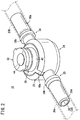
- FIG. 2 is a perspective view illustrating the entire configuration of the connector 10 according to an illustrative example of a connector not falling under the scope of the claims.
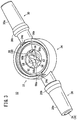
- Fig. 3 is a perspective view illustrating the connector 10 of Fig. 2 with a lid 26 detached therefrom.
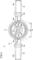
- Fig. 4 is a plan view of the connector 10 of Fig. 3 .
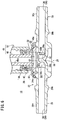
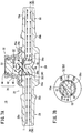
- Fig. 5 is a side cross-sectional view of the connector 10 of Fig. 2 .
- the connector 10 includes a housing 22 which has a flow path of an infusion line (including a main line and another line) formed inside thereof.
- the housing 22 is formed of a resin material that is hard relative to the tube 20 having flexibility.
- the constituent material of the housing 22 include polyethylene, polypropylene, polyolefin such as ethylene-vinyl acetate copolymers, polyurethane, polyamide, polyester, polycarbonate, polybutadiene, and polyvinyl chloride.
- the housing 22 includes a connector base 24 having a bottomed tubular shape, the lid 26 which is attached to the connector base 24 so as to block an upper side opening of the connector base 24, and a first port 28 and a second port 30 each of which is coupled to the side peripheral surface of the connector base 24.
- the first tube 20a is connected to the first port 28, and the second tube 20b is connected to the second port 30.
- a third port (connection terminal) 32 to which the third tube 20c is connected is arranged continuous with the upper surface of the lid 26.
- the first port 28 is formed into a generally cylindrical shape.
- the first port 28 has a proximal end which is continuous with the connector base 24 and a tip end which linearly extends toward the upstream side of the infusion line.
- An inner cavity of the first port 28 serves as a first port flow path 34 which can allow the infusion fluid T to flow therethrough (refer to Fig. 5 ).
- the outer shape of the first port 28 is formed into a male luer taper.
- the first port 28 is inserted into the first tube 20a (the inner cavity of the first tube 20a). That is, a tapered surface 28a whose diameter slightly expands from the tip end toward the proximal end is formed on the outer peripheral surface of the first port 28. Accordingly, the tip end of the first port 28 can be easily inserted into the first tube 20a when the first port 28 is connected to the first tube 20a. Further, a projection 28b is formed on the proximal side with respect to the tapered surface 28a. Accordingly, by allowing the first tube 20a to advance beyond the projection 28b, the first tube 20a does not easily come off, and the first tube 20a and the first port 28 can be liquid-tightly connected to each other.
- the second port 30 is coupled to the connector base 24 on the opposite side of the first port 28.
- the second port 30 has a proximal end which is continuous with the connector base 24 and a tip end which linearly extends toward the downstream side of the infusion line. That is, the first port 28 and the second port 30 are formed so as to be linearly arranged in a row with their axes coincide with each other in plan view (refer to Fig. 4 ).
- An inner cavity of the second port 30 serves as a second port flow path 36 which can allow an infusion fluid to flow therethrough (refer to Fig. 5 ).
- the second port 30 is formed into the same shape as the first port 28 (a male luer taper having a tapered surface 30a and a projection 30b on the outer peripheral surface thereof), and can obtain the same effect as the first tube 20a when being connected to the second tube 20b.
- a method of connecting the first and second tubes 20a and 20b and the first and second ports example 28 and 30 is not limited to the present example.
- connection mechanisms may be provided on the distal ends of the first and second tubes 20a and 20b and the distal ends of the first and second ports 28 and 30 to achieve easy attachment/detachment.
- the first port flow path 34 and the second port flow path 36 serve as a flow path of a main line of the infusion fluid T (hereinbelow, referred to as a main line flow path 38). That is, the main line flow path 38 is formed so that an extension line of the axis of the first port flow path 34 (in the axial direction) and an extension line of the axis of the second port flow path 36 (in the axial direction) coincide with each other in plan view and side view.
- the third port 32 is formed in a direction perpendicular to the axial direction of the first port 28 and the second port 30.
- the connector 10 according to the above example is configured as a T-shaped connector in which the branch angle of the third port 32 with respect to the main line flow path 38 is 90 degree.
- the third port 32 allows an infusion fluid supplied through the third tube 20c to join the infusion fluid T flowing in the main line flow path 38.
- the lid 26 in which the third port 32 is formed is configured as a single unit which includes an outer casing 40, an inner casing 42, and a valve 44.
- Each of the outer casing 40 and the inner casing 42 is formed as a cylindrical body.
- the lid26 is attached to the upper side of the connector base 24 so that the outer casing 40 covers the outer peripheral surface and the upper surface of the inner casing 42.
- the valve 44 is formed of an elastic material.
- the peripheral edge of the valve 44 is interposed between the outer casing 40 and the inner casing 42, so that the valve 44 is held on the upper part of the lid 26.
- the valve 44 self-blocks the third port 32 when the third tube 20c is not connected.
- the valve 44 is elastically deformed in response to the entrance of a plug 46 (refer to Fig. 6 ) to thereby liquid-tightly connect the plug 46 thereto.
- the third port 32 is formed so as to have a predetermined thickness by stacking the cylindrical bodies of the outer casing 40 and the inner casing 42 in the diameter direction. In this case, an opening on one end of the third port 32 is connected to the main line flow path 38 of the connector base 24.
- the valve 44 is arranged on an opening on the other end of the third port 32.
- Fig. 6 is a side cross-sectional view illustrating a state where the plug 46 of the third tube 20c is connected to the third port 32 of the connector 10 of Fig. 5 .
- the plug 46 of the third tube 20c is inserted into the third port 32.
- the plug 46 is standardized, for example, by ISO.
- the plug 46 of the third tube 20c includes an inner tube 48 which has a flow path of another line of the infusion fluid T (hereinbelow, referred to as another line flow path 48a) inside thereof and an outer tube 50 which surrounds the inner tube 48.
- the plug 46 holds the third port 32 between the outer periphery of the inner tube 48 and the inner periphery of the outer tube 50.
- the third port 32 has a connection side space 52 which can attach and hold the plug 46.
- the connection side space 52 is surrounded by an inner wall 53 (refer to Fig. 5 ) of the inner casing 42 which forms the cylindrical body.
- the inner tube 48 of the plug 46 is inserted into the connection side space 52 so as to push the valve 44 thereinto. Accordingly, the valve 44 and the inner tube 48 are liquid-tightly fitted to and held by the inner wall 53 of the inner casing 42, and the another line flow path 48a communicates with the main line flow path 38 through the connection side space 52.
- connection side space 52 is formed as a space having a predetermined volume by the valve 44 and the inner wall 53. Further, the connection side space 52 is provided continuous with the linearly formed main line flow path 38 so as to be deviated upward from the main line flow path 38 in side view. Therefore, when the plug 46 is not inserted into the third port 32, the infusion fluid T flowing in the main line flow path 38 flows into the connection side space 52.
- the lid 26 which has the third port 32 having the above configuration is attached to the upper side opening of the connector base 24 which is formed into a bottomed tubular shape (refer to Fig. 2 ).
- a flow path groove (flow path side space) 54 is provided inside the connector base 24.
- the flow path groove 54 penetrates the connector base 24 along the axial direction of the first port 28 and the second port 30 (linearly).
- the pair of engagement portions 24a on which the locking claws 40a are hooked are formed on the upper side of the side peripheral wall of the connector base 24 in the formation direction of the first port 28 and the second port 30.
- the flow path groove 54 is continuous with the connection side space 52. Accordingly, an integrated space is formed in a central part of the connector 10 by the connection side space 52 and the flow path groove 54 (refer to Fig. 5 ).
- the flow path groove 54 includes a bottom part 58 which faces the connection side space 52 and a pair of side parts 60a and 60b which extend from opposite sides of the bottom part 58 toward the connection side space 52.
- the first port flow path 34 communicates with one end in the extending direction of the flow path groove 54
- the second port flow path 36 communicates with the other end thereof. That is, the main line flow path 38 of the connector 10 includes the first port flow path 34, the flow path groove 54, and the second port flow path 36 in this order from the upstream side toward the downstream side.
- These flow paths (and the groove) are linearly formed so as to be continuous with each other.
- a rib 56 which extends obliquely with respect to the axial direction of the main line flow path 38 is formed on the bottom part 58 of the flow path groove 54 at an intermediate position in the extending direction of the flow path groove 54.
- the rib 56 is formed so as to be lower than the side parts 60a and 60b of the flow path groove 54, and has a function to direct the infusion fluid T flowing through the main line flow path 38 to the downstream side and, at the same time, guide the infusion fluid T to the connection side space 52 located above along a wall surface 56a.
- one end thereof is coupled to the side part 60a and the coupled part therebetween is located on the upstream side with respect to the center in the extending direction of the flow path groove 54, and the other end thereof is coupled to the side part 60b and the coupled part therebetween is located on the downstream side with respect to the center in the extending direction of the flow path groove 54.
- the rib 56 includes wall surfaces 56a on both sides facing the first port flow path 34 and the second port flow path 36. Each of these wall surfaces 56a is formed on the bottom part 58 so as to extend obliquely with respect to the axial direction of the main line flow path 38 in plan view (refer to Fig. 4 ) on the basis of the shape of the rib 56. The respective ends of each of the wall surfaces 56a are coupled to the side parts 60a and 60b. Therefore, when viewed from the upstream side of the flow path groove 54, each of the wall surfaces 56a is formed so that one end thereof which is coupled to the side part 60a is located on the front side and the other end thereof which is coupled to the side part 60b is located on the depth side.
- a part of the rib 56 is formed into a curved shape (a curved portion 56b).
- the curved portion 56b has a function to smoothly guide the infusion fluid T which flows from the upstream side to the rib 56 to the connection side space 52 located above.
- a pair of constricted portions 62 which gradually narrow the width of the flow path groove 54 are formed on the side parts 60a and 60b so as to inwardly extend at an intermediate position in the extending direction of the flow path groove 54.
- the pair of constricted portions 62 can temporarily guide the infusion fluid T flowing in the flow path groove 54 to the inner side to thereby increase the amount of the infusion fluid T guided by the rib 56.
- the connector 10 is basically configured as described above. Next, an operation and an effect when using the connector 10 will be described. As described above, the connector 10 can connect the first to third tubes 20a to 20c to perform fluid infusion. However, since the connector 10 according to the above example can obtain a larger effect when the third tube 20c is not connected thereto, a case where only the first tube 20a and the second tube 20b are connected to the connector 10 will be described in detail in the following description.
- Fig. 7A is a side cross-sectional view schematically illustrating the flow of the infusion fluid T in the connector example 10 according to the example; and Fig. 7B is a main part enlarged plan view schematically illustrating the flow of the example infusion fluid T in the connector 10 according to the example.
- the first tube 20a (refer to Fig. 1 ) is connected to the first port 28 located on the upstream side, and the second tube 20b (refer to Fig. 1 ) is connected to the second port 30 located on the downstream side.
- the infusion fluid T flows through the connector 10.
- the third port 32 into which the plug 46 (refer to Fig. 6 ) of the third tube 20c is inserted is in a blocked state by the valve 44.
- the infusion fluid T supplied from an infusion bag flows into the connector 10 through the first tube 20a. Then, as illustrated in Fig. 7A , the infusion fluid T passes through the main line flow path 38 inside the connector 10, and flows out of the connector 10. Then, the infusion fluid T is administered (supplied) to a living body through an indwelling needle which is connected to the downstream side of the connector 10.
- the infusion fluid T flows from the inside of the first tube 20a into the first port flow path 34, and advances straight (linearly moves) toward the downstream side (the connector base 24) along the first port flow path 34.
- the infusion fluid T that has moved to the connector base 24 linearly flows into the flow path groove 54. Then, the movement of the infusion fluid T is guided in a predetermined direction by the rib 56 which is provided in a standing manner at the intermediated position in the extending direction of the flow path groove 54.
- the infusion fluid T that has moved from the upstream side moves in an oblique direction by one of the wall surfaces 56a which obliquely extends in plan view. That is, the infusion fluid T is guided so as to flow toward the side part 60b having depth from the side part 60a located on the front side along the wall surface 56a of the rib 56 which is opposed to a travelling direction of the infusion fluid T. Therefore, the travelling direction of the infusion fluid T is inclined toward the side part 60b with respect to the axial direction of the main line flow path 38.
- the rib 56 (wall surface 56a) is provided in a standing manner so as to extend upward from the bottom part 58, the travelling direction of the infusion fluid T that has advanced straight from the first port flow path 34 is inclined upward.
- the wall surface 56a of the rib 56 has the curved portion 56b at the coupled part with the bottom part 58, it is possible to smoothly guide the infusion fluid T upward from the bottom part 58.
- the infusion fluid T is guided by the wall surface 56a in the lateral direction (a direction to flow toward the side part 60b) and in the upper direction.
- the infusion fluid T flows obliquely upward, and therefore easily flows into the connection side space 52.
- the infusion fluid T is concentrated on a part of the connection side space 52 (near above the side part 60b in Fig. 7B ) by the obliquely upward flow.
- the infusion fluid T that has been guided so as to be concentrated on a part of the connection side space 52 flows around in the circumferential direction by the inner wall 53 opposed thereto. As a result, a large flow (turbulence of fluid) is generated inside the connection side space 52.
- connection side space of a connector since the flow of fluid (infusion fluid or air bubbles) is not generated, a phenomenon such that fluid stagnates inside the connection side space (stagnating fluid) occurs.
- a conventional connector (refer to Japanese Unexamined Patent Application Publication (Translation of PCT Application) No. 2010-505551 , for example) simply guides an infusion fluidupward. Therefore, since the guided infusion fluid relatively calmly flows inside the connection side space, the infusion fluid hardly affects the stagnating fluid and flows out to the downstream side. Therefore, it has been difficult to discharge the stagnating fluid from the connection side space.
- the rib 56 guides the infusion fluid T obliquely upward with respect to the axial direction of the main line flow path 38. That is, by directing the infusion fluid T not only to the upper direction, but also to the lateral direction by the rib 56, a flow in the circumferential direction (lateral direction) is generated inside the connection side space 52. Accordingly, it is possible to make turbulence of the entire fluid inside the connection side space 52 large to accelerate the flow, thereby agitating stagnating fluid. In other words, fluid (infusion fluid or air bubbles) that stagnates inside the connection side space 52 is easily mixed into the infusion fluid T.
- connection side space 52 a relatively large amount of stagnating fluid exists near the inner wall 53 of the connection side space 52.
- the infusion fluid T flows along the circumferential direction of the inner wall 53, it is possible to efficiently allow stagnating fluid to flow. Further, the infusion fluid T containing stagnating fluid moves from the connection side space 52 to the opposite side (downstream side) in the flow path groove 54 beyond the rib 56. As a result, the stagnating fluid can be discharged from the connection side space 52.
- the infusion fluid T containing the stagnating fluid flows from the flow path groove 54 into the second port flow path 36, linearly moves along the second port flow path 36, and flows out into the second tube 20b located on the downstream side.
- a necessary process can be performed on the infusion fluid T containing the stagnating fluid that has flown out of the connector 10 according to the kind of the stagnating fluid and the condition of the fluid infusion.
- air bubbles air
- an infusion fluid that is different from the infusion fluid T to be supplied remains as stagnating fluid inside the connection side space 52, it is possible to perform a process of discharging the infusion fluid T for a predetermined period of time on the downstream side of the connector 10.
- the wall surface 56a is inclined so as to direct the infusion fluid T to the side part 60b. Accordingly, the infusion fluid T canbe guided so that the turbulence of stagnating fluid existing inside the connection side space 52 is made large to accelerate the flow. Therefore, fluid stagnating inside the connection side space 52 can be easily discharged from the connection side space 52 by the infusion fluid T guided by the wall surface 56a. As a result, in the infusion line to which the connector 10 is applied, the safety of fluid infusion can be significantly enhanced, and a desired infusion fluid can be excellently supplied to a patient.
- the wall surface 56a is provided in a standing manner from the bottom part 58 so as to obliquely extend on the bottom part 58, and the opposite ends thereof are coupled to the pair of side parts 60a and 60b. Accordingly, the entire infusion fluid T flowing in the axial direction of the main line flow path 38 can be directed to one direction. Then, the infusion fluid T directed to one direction is guided to the connection side space 52, thereby making it possible to make the flow (turbulence) of stagnating fluid inside the connection side space 52 larger to accelerate the flow. As a result, it is possible to more efficiently discharge the stagnating fluid inside the connection side space 52.
- the coupled part of the wall surface 56a is formed as the curved portion 56b, even the infusion fluid T flowing on the side of the bottom part 58 of the main line flow path 38 can be easily guided to the connection side space 52. Therefore, the amount of infusion fluid T guided to the connection side space 52 increases, thereby making it possible to make the flow of stagnating fluid inside the connection side space 52 further larger.
- the wall surfaces 56a are formed on both sides of the rib 56, the both sides facing the first port flow path 34 and the second port flow path 36 divided by the rib 56. Accordingly, in either case where each of the first port 28 and the second port 30 formed in the housing 22 is attached to the first tube 20a or the second tube 20b, either one of the wall surfaces 56a can be made to face the travelling direction of the infusion fluid T. As a result, connection of the connector 10 can be simplified.
- the constricted portion 62 is formed on the side part 60b of the flow path groove 54, the infusion fluid T can be temporarily gathered to the inner side. Accordingly, it is possible to increase the flow velocity of the infusion fluid T as well as direct the travelling direction of the infusion fluid T obliquely upward. As a result, the infusion fluid T can be easily guided to the connection side space 52.
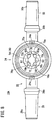
- Fig. 8 is a plan view illustrating the entire configuration of the connector 10A according to an embodiment of the invention.
- the same configurations or configurations achieving the same functions as those of the connector 10 according to the above example will be denoted by the same reference numerals, and description of these configurations will be omitted.
- the connector 10A according to the embodiment is different from the connector 10 according to the above example in that the shape of a rib 70 is formed into a generally cross shape which is different from the shape of the rib 56. More specifically, the rib 70 of the connector 10A is provided in a standing manner on a bottom part 58 of a main line flow path 38, and has a top part 72 located on the central axis of the main line flow path 38 in plan view. A wall surface 70a of the rib 70 is formed so as to obliquely extend from the top part 72 toward a pair of side parts 60a and 60b, and coupled to the pair of side parts 60a and 60b. In this manner, even when the rib 70 is formed into a generally cross shape, it is possible to guide the infusion fluid T so as to generate a large flow inside a connection side space 52 to accelerate agitation of stagnating fluid.
- the infusion fluid T flowing from a first port 28 is divided into two directions from the top part 72 of the rib 70 as a base point, the top part 72 being located on the axis of the main line flow path 38 (flow path groove 54), toward one direction from the top part 72, the side part 60a and toward another direction from the top part 72, the side part 60b. Even when being divided into two directions by the wall surface 70a, the infusion fluid T is guided so as to flow toward the side part 60a and the side part 60b in the respective directions.
- the infusion fluid T that has been guided to two oblique directions flows into the connection side space 52, thereby making it possible to make the flow (turbulence) of stagnating fluid large inside the connection side space 52.
- the wall surface 70a of the embodiment stagnating fluid inside the connection side space 52 can be efficiently discharged.
- the wall surface 70a has a curved portion 70b at a position coupled to the bottom part 58. Accordingly, in the same manner as in the curved portion 56b of the rib 56 of the above example, the infusion fluid T can be smoothly guided to the connection side space 52 located above.
- wall surfaces 70a can be formed on both sides of the rib 70, the both sides facing a first port flow path 34 and a second port flow path 36 divided by the rib 70. Therefore, in either case where each of the first port 28 and the second port 30 formed in the housing 22 is attached to the first tube 20a or the second tube 20b, either one of the wall surfaces 70a can be made to face the travelling direction of the infusion fluid T. As a result, connection of the connector 10A can be simplified.
- Fig. 9 is a plan view illustrating the entire configuration of a connector 10B as a reference example.
- the connector 10B according to the reference example is different from the connector 10 according to the above example and the connector 10A according to the embodiment in that a central part in the width direction of a rib 80 is formed into a generally recessed shape recessed along the travelling direction. More specifically, a wall surface 80a of the rib 80 is provided in a standing manner on a bottom part 58 of a main line flow path 38, and curved into an arc shape from a pair of side parts 60a and 60b toward the central axis of the main line flow path 38 in plan view. A top part (valley portion 82) of the wall surface 80a on the central axis is the deepest part. It is conceivable that the connector 10B has such a rib 80 (wall surface 80a) formed on the main line flow path 38.
- connectors 10 and 10A according to the present invention are not limited to the above embodiment, and can have various configurations without departing from the scope of the invention.
Landscapes
- Health & Medical Sciences (AREA)
- Heart & Thoracic Surgery (AREA)
- Pulmonology (AREA)
- Engineering & Computer Science (AREA)
- Anesthesiology (AREA)
- Biomedical Technology (AREA)
- Hematology (AREA)
- Life Sciences & Earth Sciences (AREA)
- Animal Behavior & Ethology (AREA)
- General Health & Medical Sciences (AREA)
- Public Health (AREA)
- Veterinary Medicine (AREA)
- Infusion, Injection, And Reservoir Apparatuses (AREA)
Description
- The present invention relates to a connector that connects a plurality of tubes to each other, for example, in an infusion line for performing fluid infusion to a patient. In particular, the presente invention relates to a connector according to the preamble of claim 1, such as it is for example known from
WO 2008/043069 . - Conventionally, when performing fluid infusion to a patient, a plurality of tubes are connected to construct an infusion line which is continuous from an infusion bag as a supply source of an infusion fluid up to the patient, and a connector is used as a tool for connecting the tubes to each other. In fluid infusion, with respect to a main line for supplying a main infusion fluid to a patient, another infusion fluid may be supplied from another line, and these infusion fluids may be mixed in a connector and directed to the patient. In this case, a connector including a three-way port which can allow an infusion fluid to flow therethrough is used (refer to Japanese Unexamined Patent Application Publication (Translation of
PCT Application) No. 2010-505551 - The connector includes a housing which has a main line flow path formed inside thereof. A connection terminal to which a plug (tube terminal) of another line is connected is formed in a body part of the housing. In this case, a plug housing space (hereinbelow, referred to as a connection side space) which is continuous with the main line flow path is provided inside the connection terminal due to the necessity of connecting a standardized plug thereto.
- The connection side space is formed at a position deviated from the main line flow path in order to ensure the insertability of the plug. Therefore, a phenomenon such that fluid (liquid, gas, or the like) existing in the connection side space stagnates in the connection side space occurs. Such fluid stagnating in the connection side space (hereinbelow, also referred to as stagnating fluid in order to distinguish it from fluid flowing in the main line flow path) may disadvantageously cause various troubles, in particular, in medical instruments.
- For example, before supplying an infusion fluid to a patient, an operation of filling up the infusion fluid inside an infusion line to remove air therefrom (also referred to as priming) is performed. However, air bubbles (air) may stagnate in a connection side space of a connector. As a result, when supplying the infusion fluid to the patient, the air bubbles remaining therein may be disadvantageously introduced into the patient together with the infusion fluid. In addition, when supplying a high nutritive liquid as an infusion fluid, the liquid stagnates inside the connection side space, and bacteria may thereby grow inside the connector. As a result, the bacteria may be disadvantageously introduced into a patient. Further, when changing an infusion fluid supplied to a patient to a next infusion fluid, if the next infusion fluid is supplied with the previously supplied infusion fluid stagnating in the connection side space, these different infusion fluids may be disadvantageously mixed and introduced into a patient.
- In order to prevent the troubles as described above, in the connector disclosed in Japanese Unexamined Patent Application Publication (Translation of
PCT Application) No. 2010-505551 - However, even when the wall is provided in a midway part of the main line flow path, and an infusion fluid is thereby guided to the connection side space as in the connector of Japanese Unexamined Patent Application Publication (Translation of
PCT Application) No. 2010-505551 WO 2008/043069 A2 ,EP 1 849 495 A1 orWO 94/15665 - The present invention has been made in view of the above circumstances, and an object thereof is to provide a connector that can efficiently discharge fluid stagnating in a connection side space in a connection terminal from the connection side space with a simple configuration, thereby enhancing the safety of fluid infusion and excellently supplying a desired fluid.
- To achieve the aforesaid object, the present invention provides a connector according to independent claim 1. The dependent claims relate to advantageous embodiments.
- With the above configuration, since the wall surface which directs fluid to the connection side space so as to flow toward at least one of the side parts, the fluid can be guided so that turbulence of stagnating fluid existing inside the connection side space is made large to accelerate the flow. Therefore, fluid stagnating inside the connection side space can be easily discharged from the connection side space by the fluid guided by the wall surface. As a result, when constructing an infusion line which administers an infusion fluid using the connector, the safety of fluid infusion can be significantly enhanced, and a desired infusion fluid can be excellently supplied to a patient.
- In this case, it is preferred that the at least one wall surface be provided on the bottom part so as to extend obliquely with respect to an axial direction of the flow path in plan view, and opposite ends of the at least one wall surface be coupled to the respective side parts.
- In this manner, since the wall surface is provided on the bottom part so as to extend obliquely with respect to the axial direction of the flow path in plan view, and the opposite ends of the wall surface is coupled to the respective side parts, the entire fluid flowing in the axial direction of the flow path can be directed to one of the side parts. Further, the fluid directed to one direction is guided to the connection side space, thereby making it possible to make the turbulence of fluid inside the connection side space larger to accelerate the flow. As a result, it is possible to more efficiently discharge the stagnating fluid inside the connection side space.
- The at least one wall surface may include a top part between the side parts in plan view and may be provided on the bottom part so as to extend from the top part obliquely with respect to an axial direction of the flow path, and opposite ends of the at least one wall surface may be coupled to the respective side parts.
- In this manner, since the wall surface includes the top part between the side parts in plan view and is provided on the bottom part so as to extend from the top part obliquely with respect to the axial direction of the flow path, and the opposite ends of the wall surface are coupled to the respective side parts, fluid flowing in the axial direction of the flow path can be divided into two directions from the top part and directed to the pair of side parts. Further, even when the fluid directed to the two directions is guided to the connection side space, it is possible to make the turbulence of fluid inside the connection side space large to accelerate the flow.
- The at least one wall surface is formed into a curved shape at a coupled part with the bottom part.
- In this manner, since the coupled part of the wall surface is formed into a curved shape, even fluid flowing on the side of the bottom part of the flow path can be easily guided to the connection side space. Therefore, the amount of fluid guided to the connection side space increases, thereby making it possible to make the turbulence of fluid inside the connection side space further larger.
- The at least one wall surface includes a plurality of wall surfaces which are provided in a rib dividing the flow path in plan view on both sides facing the divided two flow paths.
- In this manner, since the wall surfaces are formed on both sides of the rib, the both sides facing the two flow paths divided by the rib, in either case where each of the two fluid flow ports formed in the housing is attached to the first tube or the second tube, fluid can be guided so as to generate a large flow inside the connection side space by either one of the wall surfaces. As a result, connection of the connector can be simplified.
- Each of the side parts preferably has a constricted portion which inwardly extends so as to gradually narrow the width of the flow path side space.
- In this manner, since the width of the flow path side space is gradually narrowed by the constricted portion, it is possible to temporarily guide fluid flowing in the flow path side space to the inner side to thereby increase the amount of fluid directed to one of the side parts by the wall surface. As a result, it is possible to generate a larger flow inside the connection side space.
- According to the present invention, it is possible to efficiently discharge fluid stagnating in a connection side space in a connection terminal from the connection side space with a simple configuration, thereby enhancing the safety of fluid infusion and excellently supplying a desired fluid.
-
-
Fig. 1 is an explanatory diagram schematically illustrating an example of a fluid infusion set to which a connector an illustrative example of a connector not falling under the scope of the claims is applied. -
Fig. 2 is a perspective view illustrating the entire configuration of a connector according to an illustrative example of a connector not falling under the scope of the claims. -
Fig. 3 is a perspective view illustrating the connector ofFig. 2 with a lid detached therefrom. -
Fig. 4 is a plan view of the connector ofFig. 3 . -
Fig. 5 is a side cross-sectional view of the connector ofFig. 2 . -
Fig. 6 is a side cross-sectional view illustrating a state where a plug of a third tube is connected to a third port of the connector ofFig. 5 . -
Fig. 7A is a side cross-sectional view schematically illustrating the flow of an infusion fluid in the an illustrative example of a connector not falling under the scope of the claims; andFig. 7B is a main part enlarged plan view schematically illustrating the flow of an infusion fluid in said connector. -
Fig. 8 is a plan view illustrating the entire configuration of a connector according to an embodiment of the invention. -
Fig. 9 is a plan view illustrating the entire configuration of a connector as a reference example. - Hereinbelow, a connector according to the present invention will be described in detail on the basis of a relationship with a fluid infusion set to which the connector can be applied. It is needless to say that the application of the connector is not limited to application to the fluid infusion set.
-
Fig. 1 is an explanatory diagram schematically illustrating an example of a fluid infusion set 12 to which an illustrative example of a connector not falling under the scope of the claims is applied. - As already described, the
connector 10 has a function to connect a plurality of tubes to each other in an infusion line for performing fluid infusion to a patient. For example, theconnector 10 is applied to the fluid infusion set 12 as illustrated inFig. 1 . The fluid infusion set 12 has an upstream end which is connected to an infusion bag (not illustrated) and a downstream end which is connected to an indwelling needle (not illustrated) . Accordingly, an infusion line that can administer (supply) an infusion fluid T (fluid: refer toFig. 7 ) to a patient is constructed. - Examples of the infusion fluid T include any fluids that can be administered to a living body such as a drug solution, a corrective electrolyte solution, and saline. When the infusion fluid is a drug solution, for example, various kinds of drugs such as a sedative, an intravenous anesthetic, an anesthetic sedative, a local anesthetic, a nondepolarizing muscle relaxant, a pressor agent, an antihypertensive agent, a coronary vasodilator, a diuretic agent, an antiarrhythmic agent, a bronchodilator, a hemostatic agent, a vitamin compound, an antibiotic, and a fat emulsion can be applied.
- As illustrated in
Fig. 1 , the fluid infusion set 12 includes adrip tube 14 which allows the amount of flow of the infusion fluid T (refer toFig. 7 ) supplied from the infusion bag to be visually confirmed, a clamp (also referred to as a klemme) 16 which adjusts the amount of flow of the infusion fluid T, anair vent filter 18 which discharges (or supplies) air existing in the infusion line, and the like. Atube 20 which can allow the infusion fluid T to flow therethrough is connected (or inserted through) between the components. The fluid infusion set 12 is, of course, not limited to the configuration illustrated inFig. 1 . Various components (an infusion pump and a check valve, for example) which are arranged in the infusion line other than the above components can be attached to the fluid infusion set 12. - The
tube 20 of the fluid infusion set 12 is a tube body having flexibility, and constitutes the infusion line through which the infusion fluid T actually flows. Examples of the constituent material of thetube 20 include soft polyvinyl chloride, ethylene-vinyl acetate copolymers, polyethylene, polypropylene, polybutadiene, and materials mainly composed of these materials. - When the
connector 10 is applied to the fluid infusion set 12 as described above, theconnector 10 is arranged, for example, between theclamp 16 and theair vent filter 18. That is, theconnector 10 has a function to connect afirst tube 20a which is connected to the downstream side of theclamp 16 and asecond tube 20b which is connected to the upstream side of theair vent filter 18 to each other to thereby allow the infusion fluid T to flow from thefirst tube 20a to thesecond tube 20b. Further, theconnector 10 is a three-port connector to which athird tube 20c which is formed, with respect to a main line formed by thefirst tube 20a and thesecond tube 20b, as another line can be connected. - The fluid infusion set 12 does not particularly limit an arrangement position of the
connector 10. When constructing the infusion line, theconnector 10 can be arranged at a desired position. Further, it is needless to say that the number ofconnectors 10 is not limited to one, and a plurality ofconnectors 10 can be arranged in the fluid infusion set 12 (infusion line). For example, twoconnectors 10 can be arranged between theclamp 16 and theair vent filter 18 and the downstream side of theair vent filter 18. - Hereinbelow, the
connector 10, an illustrative example of a connector not falling under the scope of the claims, and aconnector 10A, an embodiment according to the present invention,which are applied to the above infusion line will be specifically described. - An illustrative example of a connector not falling under the scope of the claims.
Fig. 2 is a perspective view illustrating the entire configuration of theconnector 10 according to an illustrative example of a connector not falling under the scope of the claims.Fig. 3 is a perspective view illustrating theconnector 10 ofFig. 2 with alid 26 detached therefrom.Fig. 4 is a plan view of theconnector 10 ofFig. 3 .Fig. 5 is a side cross-sectional view of theconnector 10 ofFig. 2 . - As illustrated in
Fig. 2 , theconnector 10 includes ahousing 22 which has a flow path of an infusion line (including a main line and another line) formed inside thereof. Thehousing 22 is formed of a resin material that is hard relative to thetube 20 having flexibility. Examples of the constituent material of thehousing 22 include polyethylene, polypropylene, polyolefin such as ethylene-vinyl acetate copolymers, polyurethane, polyamide, polyester, polycarbonate, polybutadiene, and polyvinyl chloride. - The
housing 22 includes aconnector base 24 having a bottomed tubular shape, thelid 26 which is attached to theconnector base 24 so as to block an upper side opening of theconnector base 24, and afirst port 28 and asecond port 30 each of which is coupled to the side peripheral surface of theconnector base 24. In this case, thefirst tube 20a is connected to thefirst port 28, and thesecond tube 20b is connected to thesecond port 30. A third port (connection terminal) 32 to which thethird tube 20c is connected is arranged continuous with the upper surface of thelid 26. - As illustrated in
Figs. 2 to 5 , thefirst port 28 is formed into a generally cylindrical shape. Thefirst port 28 has a proximal end which is continuous with theconnector base 24 and a tip end which linearly extends toward the upstream side of the infusion line. An inner cavity of thefirst port 28 serves as a firstport flow path 34 which can allow the infusion fluid T to flow therethrough (refer toFig. 5 ). - The outer shape of the
first port 28 is formed into a male luer taper. Thefirst port 28 is inserted into thefirst tube 20a (the inner cavity of thefirst tube 20a). That is, atapered surface 28a whose diameter slightly expands from the tip end toward the proximal end is formed on the outer peripheral surface of thefirst port 28. Accordingly, the tip end of thefirst port 28 can be easily inserted into thefirst tube 20a when thefirst port 28 is connected to thefirst tube 20a. Further, aprojection 28b is formed on the proximal side with respect to the taperedsurface 28a. Accordingly, by allowing thefirst tube 20a to advance beyond theprojection 28b, thefirst tube 20a does not easily come off, and thefirst tube 20a and thefirst port 28 can be liquid-tightly connected to each other. - On the other hand, the
second port 30 is coupled to theconnector base 24 on the opposite side of thefirst port 28. Thesecond port 30 has a proximal end which is continuous with theconnector base 24 and a tip end which linearly extends toward the downstream side of the infusion line. That is, thefirst port 28 and thesecond port 30 are formed so as to be linearly arranged in a row with their axes coincide with each other in plan view (refer toFig. 4 ). An inner cavity of thesecond port 30 serves as a secondport flow path 36 which can allow an infusion fluid to flow therethrough (refer toFig. 5 ). - The
second port 30 is formed into the same shape as the first port 28 (a male luer taper having a taperedsurface 30a and aprojection 30b on the outer peripheral surface thereof), and can obtain the same effect as thefirst tube 20a when being connected to thesecond tube 20b. A method of connecting the first andsecond tubes second tubes second ports - In the
connector 10, the firstport flow path 34 and the secondport flow path 36 serve as a flow path of a main line of the infusion fluid T (hereinbelow, referred to as a main line flow path 38). That is, the mainline flow path 38 is formed so that an extension line of the axis of the first port flow path 34 (in the axial direction) and an extension line of the axis of the second port flow path 36 (in the axial direction) coincide with each other in plan view and side view. - As illustrated in
Fig. 5 , thethird port 32 is formed in a direction perpendicular to the axial direction of thefirst port 28 and thesecond port 30. In other words, theconnector 10 according to the above example is configured as a T-shaped connector in which the branch angle of thethird port 32 with respect to the mainline flow path 38 is 90 degree. Thethird port 32 allows an infusion fluid supplied through thethird tube 20c to join the infusion fluid T flowing in the mainline flow path 38. - The
lid 26 in which thethird port 32 is formed is configured as a single unit which includes anouter casing 40, aninner casing 42, and avalve 44. Each of theouter casing 40 and theinner casing 42 is formed as a cylindrical body. An end of each of theouter casing 40 and theinner casing 42, the end being connected to theconnector base 24, forms a flange portion extending in the outer diameter direction. The lid26 is attached to the upper side of theconnector base 24 so that theouter casing 40 covers the outer peripheral surface and the upper surface of theinner casing 42. When attaching thelid 26 to theconnector base 24, a pair of lockingclaws 40a which are provided in the outer casing 40 (flange portion) along the formation direction of thefirst port 28 and thesecond port 30 are hooked onengagement portions 24a of theconnector base 24 to thereby hold theengagement portions 24a by the lockingclaws 40a and the outer edge of theinner casing 42. As a result, it is possible to firmly fix thelid 26 to theconnector base 24. - The
valve 44 is formed of an elastic material. The peripheral edge of thevalve 44 is interposed between theouter casing 40 and theinner casing 42, so that thevalve 44 is held on the upper part of thelid 26. Thevalve 44 self-blocks thethird port 32 when thethird tube 20c is not connected. On the other hand, when thethird tube 20c is connected, thevalve 44 is elastically deformed in response to the entrance of a plug 46 (refer toFig. 6 ) to thereby liquid-tightly connect theplug 46 thereto. - The
third port 32 is formed so as to have a predetermined thickness by stacking the cylindrical bodies of theouter casing 40 and theinner casing 42 in the diameter direction. In this case, an opening on one end of thethird port 32 is connected to the mainline flow path 38 of theconnector base 24. Thevalve 44 is arranged on an opening on the other end of thethird port 32. -
Fig. 6 is a side cross-sectional view illustrating a state where theplug 46 of thethird tube 20c is connected to thethird port 32 of theconnector 10 ofFig. 5 . - As illustrated in
Fig. 6 , theplug 46 of thethird tube 20c is inserted into thethird port 32. Theplug 46 is standardized, for example, by ISO. Specifically, theplug 46 of thethird tube 20c includes aninner tube 48 which has a flow path of another line of the infusion fluid T (hereinbelow, referred to as anotherline flow path 48a) inside thereof and anouter tube 50 which surrounds theinner tube 48. Theplug 46 holds thethird port 32 between the outer periphery of theinner tube 48 and the inner periphery of theouter tube 50. - On the other hand, the
third port 32 has aconnection side space 52 which can attach and hold theplug 46. Theconnection side space 52 is surrounded by an inner wall 53 (refer toFig. 5 ) of theinner casing 42 which forms the cylindrical body. Theinner tube 48 of theplug 46 is inserted into theconnection side space 52 so as to push thevalve 44 thereinto. Accordingly, thevalve 44 and theinner tube 48 are liquid-tightly fitted to and held by theinner wall 53 of theinner casing 42, and the anotherline flow path 48a communicates with the mainline flow path 38 through theconnection side space 52. - As illustrated in
Fig. 5 , when thevalve 44 self-blocks the third port 32 (that is, when theplug 46 is not inserted into the third port 32), theconnection side space 52 is formed as a space having a predetermined volume by thevalve 44 and theinner wall 53. Further, theconnection side space 52 is provided continuous with the linearly formed mainline flow path 38 so as to be deviated upward from the mainline flow path 38 in side view. Therefore, when theplug 46 is not inserted into thethird port 32, the infusion fluid T flowing in the mainline flow path 38 flows into theconnection side space 52. - The
lid 26 which has thethird port 32 having the above configuration is attached to the upper side opening of theconnector base 24 which is formed into a bottomed tubular shape (refer toFig. 2 ). As illustrated inFig. 3 , a flow path groove (flow path side space) 54 is provided inside theconnector base 24. The flow path groove 54 penetrates theconnector base 24 along the axial direction of thefirst port 28 and the second port 30 (linearly). Further, as described above, the pair ofengagement portions 24a on which the lockingclaws 40a are hooked are formed on the upper side of the side peripheral wall of theconnector base 24 in the formation direction of thefirst port 28 and thesecond port 30. - In a state where the
lid 26 is attached to theconnector base 24, the flow path groove 54 is continuous with theconnection side space 52. Accordingly, an integrated space is formed in a central part of theconnector 10 by theconnection side space 52 and the flow path groove 54 (refer toFig. 5 ). - The flow path groove 54 includes a
bottom part 58 which faces theconnection side space 52 and a pair ofside parts bottom part 58 toward theconnection side space 52. The firstport flow path 34 communicates with one end in the extending direction of theflow path groove 54, and the secondport flow path 36 communicates with the other end thereof. That is, the mainline flow path 38 of theconnector 10 includes the firstport flow path 34, theflow path groove 54, and the secondport flow path 36 in this order from the upstream side toward the downstream side. These flow paths (and the groove) are linearly formed so as to be continuous with each other. - A
rib 56 which extends obliquely with respect to the axial direction of the mainline flow path 38 is formed on thebottom part 58 of the flow path groove 54 at an intermediate position in the extending direction of theflow path groove 54. Therib 56 is formed so as to be lower than theside parts flow path groove 54, and has a function to direct the infusion fluid T flowing through the mainline flow path 38 to the downstream side and, at the same time, guide the infusion fluid T to theconnection side space 52 located above along awall surface 56a. In therib 56 according to the above example, one end thereof is coupled to theside part 60a and the coupled part therebetween is located on the upstream side with respect to the center in the extending direction of theflow path groove 54, and the other end thereof is coupled to theside part 60b and the coupled part therebetween is located on the downstream side with respect to the center in the extending direction of theflow path groove 54. - The
rib 56 includes wall surfaces 56a on both sides facing the firstport flow path 34 and the secondport flow path 36. Each of thesewall surfaces 56a is formed on thebottom part 58 so as to extend obliquely with respect to the axial direction of the mainline flow path 38 in plan view (refer toFig. 4 ) on the basis of the shape of therib 56. The respective ends of each of the wall surfaces 56a are coupled to theside parts flow path groove 54, each of thewall surfaces 56a is formed so that one end thereof which is coupled to theside part 60a is located on the front side and the other end thereof which is coupled to theside part 60b is located on the depth side. - As illustrated in
Fig. 5 , a part of therib 56, the part being coupled to thebottom part 58, is formed into a curved shape (acurved portion 56b). Thecurved portion 56b has a function to smoothly guide the infusion fluid T which flows from the upstream side to therib 56 to theconnection side space 52 located above. - A pair of constricted
portions 62 which gradually narrow the width of the flow path groove 54 are formed on theside parts flow path groove 54. The pair of constrictedportions 62 can temporarily guide the infusion fluid T flowing in the flow path groove 54 to the inner side to thereby increase the amount of the infusion fluid T guided by therib 56. - The
connector 10 is basically configured as described above. Next, an operation and an effect when using theconnector 10 will be described. As described above, theconnector 10 can connect the first tothird tubes 20a to 20c to perform fluid infusion. However, since theconnector 10 according to the above example can obtain a larger effect when thethird tube 20c is not connected thereto, a case where only thefirst tube 20a and thesecond tube 20b are connected to theconnector 10 will be described in detail in the following description. -
Fig. 7A is a side cross-sectional view schematically illustrating the flow of the infusion fluid T in the connector example 10 according to the example; andFig. 7B is a main part enlarged plan view schematically illustrating the flow of the example infusion fluid T in theconnector 10 according to the example. - In the
connector 10, thefirst tube 20a (refer toFig. 1 ) is connected to thefirst port 28 located on the upstream side, and thesecond tube 20b (refer toFig. 1 ) is connected to thesecond port 30 located on the downstream side. In this state, the infusion fluid T flows through theconnector 10. On the other hand, thethird port 32 into which the plug 46 (refer toFig. 6 ) of thethird tube 20c is inserted is in a blocked state by thevalve 44. - The infusion fluid T supplied from an infusion bag flows into the
connector 10 through thefirst tube 20a. Then, as illustrated inFig. 7A , the infusion fluid T passes through the mainline flow path 38 inside theconnector 10, and flows out of theconnector 10. Then, the infusion fluid T is administered (supplied) to a living body through an indwelling needle which is connected to the downstream side of theconnector 10. - In this case, inside the
connector 10, the infusion fluid T flows from the inside of thefirst tube 20a into the firstport flow path 34, and advances straight (linearly moves) toward the downstream side (the connector base 24) along the firstport flow path 34. - The infusion fluid T that has moved to the
connector base 24 linearly flows into theflow path groove 54. Then, the movement of the infusion fluid T is guided in a predetermined direction by therib 56 which is provided in a standing manner at the intermediated position in the extending direction of theflow path groove 54. - Specifically, as illustrated in
Fig. 7B , the infusion fluid T that has moved from the upstream side (the left side inFig. 7B ) moves in an oblique direction by one of the wall surfaces 56a which obliquely extends in plan view. That is, the infusion fluid T is guided so as to flow toward theside part 60b having depth from theside part 60a located on the front side along thewall surface 56a of therib 56 which is opposed to a travelling direction of the infusion fluid T. Therefore, the travelling direction of the infusion fluid T is inclined toward theside part 60b with respect to the axial direction of the mainline flow path 38. - As illustrated in
Fig. 7A , since the rib 56 (wall surface 56a) is provided in a standing manner so as to extend upward from thebottom part 58, the travelling direction of the infusion fluid T that has advanced straight from the firstport flow path 34 is inclined upward. In this case, since thewall surface 56a of therib 56 has thecurved portion 56b at the coupled part with thebottom part 58, it is possible to smoothly guide the infusion fluid T upward from thebottom part 58. - In this manner, the infusion fluid T is guided by the
wall surface 56a in the lateral direction (a direction to flow toward theside part 60b) and in the upper direction. As a result, the infusion fluid T flows obliquely upward, and therefore easily flows into theconnection side space 52. Further, the infusion fluid T is concentrated on a part of the connection side space 52 (near above theside part 60b inFig. 7B ) by the obliquely upward flow. Inside theconnection side space 52, the infusion fluid T that has been guided so as to be concentrated on a part of theconnection side space 52 flows around in the circumferential direction by theinner wall 53 opposed thereto. As a result, a large flow (turbulence of fluid) is generated inside theconnection side space 52. - As described above, in a connection side space of a connector, since the flow of fluid (infusion fluid or air bubbles) is not generated, a phenomenon such that fluid stagnates inside the connection side space (stagnating fluid) occurs. A conventional connector (refer to Japanese Unexamined Patent Application Publication (Translation of
PCT Application) No. 2010-505551 - On the other hand, the
rib 56 according to the present invention guides the infusion fluid T obliquely upward with respect to the axial direction of the mainline flow path 38. That is, by directing the infusion fluid T not only to the upper direction, but also to the lateral direction by therib 56, a flow in the circumferential direction (lateral direction) is generated inside theconnection side space 52. Accordingly, it is possible to make turbulence of the entire fluid inside theconnection side space 52 large to accelerate the flow, thereby agitating stagnating fluid. In other words, fluid (infusion fluid or air bubbles) that stagnates inside theconnection side space 52 is easily mixed into the infusion fluid T. - In particular, a relatively large amount of stagnating fluid exists near the
inner wall 53 of theconnection side space 52. However, as described above, since the infusion fluid T flows along the circumferential direction of theinner wall 53, it is possible to efficiently allow stagnating fluid to flow. Further, the infusion fluid T containing stagnating fluid moves from theconnection side space 52 to the opposite side (downstream side) in the flow path groove 54 beyond therib 56. As a result, the stagnating fluid can be discharged from theconnection side space 52. - The infusion fluid T containing the stagnating fluid flows from the flow path groove 54 into the second
port flow path 36, linearly moves along the secondport flow path 36, and flows out into thesecond tube 20b located on the downstream side. - A necessary process can be performed on the infusion fluid T containing the stagnating fluid that has flown out of the
connector 10 according to the kind of the stagnating fluid and the condition of the fluid infusion. For example, when performing priming of the infusion line, air bubbles (air) are assumed as stagnating fluid inside theconnection side space 52. Therefore, it is possible to perform a process of discharging air bubbles in theair vent filter 18. When it is assumed that an infusion fluid that is different from the infusion fluid T to be supplied remains as stagnating fluid inside theconnection side space 52, it is possible to perform a process of discharging the infusion fluid T for a predetermined period of time on the downstream side of theconnector 10. - As described above, in the
connector 10, thewall surface 56a is inclined so as to direct the infusion fluid T to theside part 60b. Accordingly, the infusion fluid T canbe guided so that the turbulence of stagnating fluid existing inside theconnection side space 52 is made large to accelerate the flow. Therefore, fluid stagnating inside theconnection side space 52 can be easily discharged from theconnection side space 52 by the infusion fluid T guided by thewall surface 56a. As a result, in the infusion line to which theconnector 10 is applied, the safety of fluid infusion can be significantly enhanced, and a desired infusion fluid can be excellently supplied to a patient. - In particular, in the above example, the
wall surface 56a is provided in a standing manner from thebottom part 58 so as to obliquely extend on thebottom part 58, and the opposite ends thereof are coupled to the pair ofside parts line flow path 38 can be directed to one direction. Then, the infusion fluid T directed to one direction is guided to theconnection side space 52, thereby making it possible to make the flow (turbulence) of stagnating fluid inside theconnection side space 52 larger to accelerate the flow. As a result, it is possible to more efficiently discharge the stagnating fluid inside theconnection side space 52. - Further, since the coupled part of the
wall surface 56a is formed as thecurved portion 56b, even the infusion fluid T flowing on the side of thebottom part 58 of the mainline flow path 38 can be easily guided to theconnection side space 52. Therefore, the amount of infusion fluid T guided to theconnection side space 52 increases, thereby making it possible to make the flow of stagnating fluid inside theconnection side space 52 further larger. - Further, the wall surfaces 56a are formed on both sides of the
rib 56, the both sides facing the firstport flow path 34 and the secondport flow path 36 divided by therib 56. Accordingly, in either case where each of thefirst port 28 and thesecond port 30 formed in thehousing 22 is attached to thefirst tube 20a or thesecond tube 20b, either one of the wall surfaces 56a can be made to face the travelling direction of the infusion fluid T. As a result, connection of theconnector 10 can be simplified. - Further, since the
constricted portion 62 is formed on theside part 60b of theflow path groove 54, the infusion fluid T can be temporarily gathered to the inner side. Accordingly, it is possible to increase the flow velocity of the infusion fluid T as well as direct the travelling direction of the infusion fluid T obliquely upward. As a result, the infusion fluid T can be easily guided to theconnection side space 52. -
Fig. 8 is a plan view illustrating the entire configuration of theconnector 10A according to an embodiment of the invention. In theconnector 10A according to the embodiment described below, the same configurations or configurations achieving the same functions as those of theconnector 10 according to the above example will be denoted by the same reference numerals, and description of these configurations will be omitted. - The
connector 10A according to the embodiment is different from theconnector 10 according to the above example in that the shape of a rib 70 is formed into a generally cross shape which is different from the shape of therib 56. More specifically, the rib 70 of theconnector 10A is provided in a standing manner on abottom part 58 of a mainline flow path 38, and has atop part 72 located on the central axis of the mainline flow path 38 in plan view. Awall surface 70a of the rib 70 is formed so as to obliquely extend from thetop part 72 toward a pair ofside parts side parts connection side space 52 to accelerate agitation of stagnating fluid. - Hereinbelow, an operation of an infusion fluid T flowing through the
connector 10A will be specifically described. The infusion fluid T flowing from afirst port 28 is divided into two directions from thetop part 72 of the rib 70 as a base point, thetop part 72 being located on the axis of the main line flow path 38 (flow path groove 54), toward one direction from thetop part 72, theside part 60a and toward another direction from thetop part 72, theside part 60b. Even when being divided into two directions by thewall surface 70a, the infusion fluid T is guided so as to flow toward theside part 60a and theside part 60b in the respective directions. - Accordingly, the infusion fluid T that has been guided to two oblique directions flows into the
connection side space 52, thereby making it possible to make the flow (turbulence) of stagnating fluid large inside theconnection side space 52. As a result, also by thewall surface 70a of the embodiment, stagnating fluid inside theconnection side space 52 can be efficiently discharged. - Further, the
wall surface 70a has acurved portion 70b at a position coupled to thebottom part 58. Accordingly, in the same manner as in thecurved portion 56b of therib 56 of the above example, the infusion fluid T can be smoothly guided to theconnection side space 52 located above. - Also in the
connector 10A, wall surfaces 70a can be formed on both sides of the rib 70, the both sides facing a firstport flow path 34 and a secondport flow path 36 divided by the rib 70. Therefore, in either case where each of thefirst port 28 and thesecond port 30 formed in thehousing 22 is attached to thefirst tube 20a or thesecond tube 20b, either one of the wall surfaces 70a can be made to face the travelling direction of the infusion fluid T. As a result, connection of theconnector 10A can be simplified. -
Fig. 9 is a plan view illustrating the entire configuration of aconnector 10B as a reference example. - The
connector 10B according to the reference example is different from theconnector 10 according to the above example and theconnector 10A according to the embodiment in that a central part in the width direction of arib 80 is formed into a generally recessed shape recessed along the travelling direction. More specifically, awall surface 80a of therib 80 is provided in a standing manner on abottom part 58 of a mainline flow path 38, and curved into an arc shape from a pair ofside parts line flow path 38 in plan view. A top part (valley portion 82) of thewall surface 80a on the central axis is the deepest part. It is conceivable that theconnector 10B has such a rib 80 (wall surface 80a) formed on the mainline flow path 38. - It is needless to say that the
connectors
Claims (3)
- A connector (10A) comprising:a housing (22);a flow path (38) provided inside the housing (22), the flow path (38) allowing fluid flowing from a first tube (20a) to flow therethrough into a second tube (20b); anda connection terminal (32) having a connection side space (52) continuous with the flow path (38), the connection terminal (32) being capable of connecting thereto a third tube (20c) through the connection side space (52), whereinthe flow path (38) includes a flow path side space (54) which is continuous with at least the connection side space (52) and defined by a bottom part (58) facing the connection side space (52) and a pair of side parts (60a, 60b) extending from opposite sides of the bottom part (58) toward the connection side space (52), and at least one wall surface (70a) directing the fluid to the connection side space (52) so as to flow toward at least one of the side partsthe at least one wall surface (70a) includes a top part (72) between the side parts (60a, 60b) in plan view and is provided on the bottom part (58) so as to extend from the top part (72) obliquely with respect to an axial direction of the flow path (38), and opposite ends of the at least one wall surface (70a) are coupled to the respective side parts (60a, 60b),characterized in thatthe at least one wall surface (70a) comprises a plurality of wall surfaces (70a) which are provided in a rib (70) dividing the flow path (38) in plan view on both sides facing the divided two flow paths (38), andthe rib (70) is formed into a generally cross shape.
- The connector (10, 10A) according to claim 1, wherein the at least one wall surface (70a) is formed into a curved shape at a coupled part with the bottom part (58).
- The connector (10, 10A) according to claim 1, wherein each of the side parts (60a, 60b) has a constricted portion (62) which inwardly extends so as to gradually narrow the width of the flow path side space (54).
Applications Claiming Priority (2)
| Application Number | Priority Date | Filing Date | Title |
|---|---|---|---|
| JP2011210214 | 2011-09-27 | ||
| PCT/JP2012/071041 WO2013047006A1 (en) | 2011-09-27 | 2012-08-21 | Connector |
Publications (3)
| Publication Number | Publication Date |
|---|---|
| EP2762194A1 EP2762194A1 (en) | 2014-08-06 |
| EP2762194A4 EP2762194A4 (en) | 2015-08-26 |
| EP2762194B1 true EP2762194B1 (en) | 2019-02-20 |
Family
ID=47995057
Family Applications (1)
| Application Number | Title | Priority Date | Filing Date |
|---|---|---|---|
| EP12837582.1A Active EP2762194B1 (en) | 2011-09-27 | 2012-08-21 | Connector |
Country Status (5)
| Country | Link |
|---|---|
| US (1) | US9089680B2 (en) |
| EP (1) | EP2762194B1 (en) |
| JP (2) | JP6006220B2 (en) |
| CN (1) | CN103826693B (en) |
| WO (1) | WO2013047006A1 (en) |
Families Citing this family (31)
| Publication number | Priority date | Publication date | Assignee | Title |
|---|---|---|---|---|
| US11229746B2 (en) | 2006-06-22 | 2022-01-25 | Excelsior Medical Corporation | Antiseptic cap |
| US9078992B2 (en) | 2008-10-27 | 2015-07-14 | Pursuit Vascular, Inc. | Medical device for applying antimicrobial to proximal end of catheter |
| US9168366B2 (en) | 2008-12-19 | 2015-10-27 | Icu Medical, Inc. | Medical connector with closeable luer connector |
| US8323249B2 (en) | 2009-08-14 | 2012-12-04 | The Regents Of The University Of Michigan | Integrated vascular delivery system |
| US8814833B2 (en) | 2010-05-19 | 2014-08-26 | Tangent Medical Technologies Llc | Safety needle system operable with a medical device |
| WO2011146769A2 (en) | 2010-05-19 | 2011-11-24 | Tangent Medical Technologies Llc | Integrated vascular delivery system |
| EP2731658B1 (en) | 2011-07-12 | 2020-04-01 | Pursuit Vascular, Inc. | Device for delivery of antimicrobial agent into trans-dermal catheter |
| JP6553357B2 (en) | 2011-09-09 | 2019-07-31 | アイシーユー・メディカル・インコーポレーテッド | Medical connector with fluid-resistant mating interface |
| CA2891255C (en) | 2012-11-12 | 2022-10-04 | Icu Medical, Inc. | Medical connector |
| USD742507S1 (en) * | 2013-01-22 | 2015-11-03 | Intersurgical Ag | Sensor with connector for resiratory circuit |
| CN105163796B (en) | 2013-03-15 | 2018-06-01 | Icu医学有限公司 | Medical connector |
| EP3028736B1 (en) * | 2013-07-31 | 2022-11-23 | Terumo Kabushiki Kaisha | Connector and transfusion set |
| AU2014364218B2 (en) | 2013-12-11 | 2019-06-06 | Icu Medical, Inc. | Check valve |
| EP3102258A4 (en) | 2014-02-04 | 2017-12-27 | ICU Medical, Inc. | Self-priming systems and methods |
| USD786427S1 (en) | 2014-12-03 | 2017-05-09 | Icu Medical, Inc. | Fluid manifold |
| USD793551S1 (en) | 2014-12-03 | 2017-08-01 | Icu Medical, Inc. | Fluid manifold |
| CA2982456A1 (en) | 2015-05-08 | 2016-11-17 | Icu Medical, Inc. | Medical connectors configured to receive emitters of therapeutic agents |
| IT201600075597A1 (en) * | 2016-07-19 | 2018-01-19 | Borla Ind | FLOW COMPONENT PARTICULARLY FOR MEDICAL LINES FOR HEMODIALYSIS |
| SI3525865T1 (en) | 2016-10-14 | 2023-01-31 | Icu Medical, Inc. | Sanitizing caps for medical connectors |
| WO2018204206A2 (en) | 2017-05-01 | 2018-11-08 | Icu Medical, Inc. | Medical fluid connectors and methods for providing additives in medical fluid lines |
| USD850615S1 (en) * | 2018-04-24 | 2019-06-04 | Gi Supply | Tube connector |
| US11541221B2 (en) | 2018-11-07 | 2023-01-03 | Icu Medical, Inc. | Tubing set with antimicrobial properties |
| US11534595B2 (en) | 2018-11-07 | 2022-12-27 | Icu Medical, Inc. | Device for delivering an antimicrobial composition into an infusion device |
| US11517732B2 (en) | 2018-11-07 | 2022-12-06 | Icu Medical, Inc. | Syringe with antimicrobial properties |
| US11541220B2 (en) | 2018-11-07 | 2023-01-03 | Icu Medical, Inc. | Needleless connector with antimicrobial properties |
| US11400195B2 (en) | 2018-11-07 | 2022-08-02 | Icu Medical, Inc. | Peritoneal dialysis transfer set with antimicrobial properties |
| CA3118905A1 (en) | 2018-11-21 | 2020-05-28 | Icu Medical, Inc. | Antimicrobial device comprising a cap with ring and insert |
| JP7167408B2 (en) * | 2019-01-28 | 2022-11-09 | 株式会社トップ | connector |
| DE102020116247A1 (en) * | 2020-06-19 | 2021-12-23 | Fresenius Medical Care Deutschland Gmbh | HOSE INSERT FOR A HYDRAULIC HOSE SET OF A BLOOD TREATMENT DEVICE |
| CA3204371A1 (en) | 2020-12-07 | 2022-06-16 | Icu Medical, Inc. | Peritoneal dialysis caps, systems and methods |
| CN113262392B (en) * | 2021-04-25 | 2022-08-09 | 泰尔茂医疗产品(杭州)有限公司 | Connector with a locking member |
Family Cites Families (9)
| Publication number | Priority date | Publication date | Assignee | Title |
|---|---|---|---|---|
| AU6087394A (en) * | 1993-01-13 | 1994-08-15 | Medex, Inc. | Needleless sample set |
| JP2006129884A (en) * | 2004-11-02 | 2006-05-25 | Kawasumi Lab Inc | Mixed injection member, connection member and medical implement |
| CA2567868C (en) * | 2005-12-02 | 2010-02-16 | Shigeaki Funamura | Connector |
| JP4769113B2 (en) * | 2005-12-02 | 2011-09-07 | 日本シャーウッド株式会社 | connector |
| US7584767B2 (en) | 2006-03-31 | 2009-09-08 | Tyco Healthcare Group Lp | Connector |
| JP4820703B2 (en) * | 2006-04-28 | 2011-11-24 | 日本シャーウッド株式会社 | Liquid infusion tool |
| JP4820708B2 (en) * | 2006-07-27 | 2011-11-24 | 日本シャーウッド株式会社 | Liquid infusion tool |
| JP4871078B2 (en) * | 2006-09-01 | 2012-02-08 | 日本コヴィディエン株式会社 | Liquid infusion tool |
| US20080086097A1 (en) | 2006-10-05 | 2008-04-10 | Becton, Dickinson And Company | Vascular access device fluid flow direction |
-
2012
- 2012-08-21 CN CN201280046663.6A patent/CN103826693B/en active Active
- 2012-08-21 EP EP12837582.1A patent/EP2762194B1/en active Active
- 2012-08-21 JP JP2013536074A patent/JP6006220B2/en active Active
- 2012-08-21 WO PCT/JP2012/071041 patent/WO2013047006A1/en active Application Filing
-
2014
- 2014-03-26 US US14/226,425 patent/US9089680B2/en active Active
-
2016
- 2016-09-08 JP JP2016175640A patent/JP6406765B2/en active Active
Non-Patent Citations (1)
| Title |
|---|
| None * |
Also Published As
| Publication number | Publication date |
|---|---|
| WO2013047006A1 (en) | 2013-04-04 |
| JP6006220B2 (en) | 2016-10-12 |
| US20140207117A1 (en) | 2014-07-24 |
| EP2762194A1 (en) | 2014-08-06 |
| US9089680B2 (en) | 2015-07-28 |
| JPWO2013047006A1 (en) | 2015-03-26 |
| CN103826693A (en) | 2014-05-28 |
| EP2762194A4 (en) | 2015-08-26 |
| JP2016198679A (en) | 2016-12-01 |
| JP6406765B2 (en) | 2018-10-17 |
| CN103826693B (en) | 2016-03-02 |
Similar Documents
| Publication | Publication Date | Title |
|---|---|---|
| EP2762194B1 (en) | Connector | |
| JP5952413B2 (en) | connector | |
| EP3687615B1 (en) | Peripheral intravenous catheters having flow diverting features | |
| JP6482508B2 (en) | Blunt needle safety drug delivery system | |
| US9717887B2 (en) | Catheter assembly blood control device and related methods | |
| EP1708782B1 (en) | Dual well port device | |
| JP5905591B2 (en) | connector | |
| JP5952415B2 (en) | Valve body and connector having the valve body | |
| US7901386B2 (en) | Liquid transfusing tube and liquid transfusing tube set | |
| JP6240245B2 (en) | connector | |
| JP4887394B2 (en) | Infusion tube set | |
| CN114173857B (en) | Three-way connector | |
| CN112351805B (en) | Enteral syringe with venting collar | |
| JP5019242B1 (en) | Medical infusion intravenous injection device | |
| JP4584240B2 (en) | Infusion tube set | |
| US10307534B2 (en) | Infusion set and connector | |
| JPH09182791A (en) | Medication instrument |
Legal Events
| Date | Code | Title | Description |
|---|---|---|---|
| PUAI | Public reference made under article 153(3) epc to a published international application that has entered the european phase |
Free format text: ORIGINAL CODE: 0009012 |
|
| 17P | Request for examination filed |
Effective date: 20140328 |
|
| AK | Designated contracting states |
Kind code of ref document: A1 Designated state(s): AL AT BE BG CH CY CZ DE DK EE ES FI FR GB GR HR HU IE IS IT LI LT LU LV MC MK MT NL NO PL PT RO RS SE SI SK SM TR |
|
| DAX | Request for extension of the european patent (deleted) | ||
| RA4 | Supplementary search report drawn up and despatched (corrected) |
Effective date: 20150723 |
|
| RIC1 | Information provided on ipc code assigned before grant |
Ipc: A61M 39/10 20060101ALI20150717BHEP Ipc: A61M 39/02 20060101AFI20150717BHEP |
|
| STAA | Information on the status of an ep patent application or granted ep patent |
Free format text: STATUS: EXAMINATION IS IN PROGRESS |
|
| 17Q | First examination report despatched |
Effective date: 20161220 |
|
| GRAP | Despatch of communication of intention to grant a patent |
Free format text: ORIGINAL CODE: EPIDOSNIGR1 |
|
| STAA | Information on the status of an ep patent application or granted ep patent |
Free format text: STATUS: GRANT OF PATENT IS INTENDED |
|
| INTG | Intention to grant announced |
Effective date: 20181108 |
|
| GRAS | Grant fee paid |
Free format text: ORIGINAL CODE: EPIDOSNIGR3 |
|
| GRAA | (expected) grant |
Free format text: ORIGINAL CODE: 0009210 |
|
| STAA | Information on the status of an ep patent application or granted ep patent |
Free format text: STATUS: THE PATENT HAS BEEN GRANTED |
|
| AK | Designated contracting states |
Kind code of ref document: B1 Designated state(s): AL AT BE BG CH CY CZ DE DK EE ES FI FR GB GR HR HU IE IS IT LI LT LU LV MC MK MT NL NO PL PT RO RS SE SI SK SM TR |
|
| REG | Reference to a national code |
Ref country code: GB Ref legal event code: FG4D |
|
| REG | Reference to a national code |
Ref country code: CH Ref legal event code: EP |
|
| REG | Reference to a national code |
Ref country code: DE Ref legal event code: R096 Ref document number: 602012056922 Country of ref document: DE |
|
| REG | Reference to a national code |
Ref country code: AT Ref legal event code: REF Ref document number: 1097387 Country of ref document: AT Kind code of ref document: T Effective date: 20190315 |
|
| REG | Reference to a national code |
Ref country code: IE Ref legal event code: FG4D |
|
| REG | Reference to a national code |
Ref country code: NL Ref legal event code: MP Effective date: 20190220 |
|
| REG | Reference to a national code |
Ref country code: LT Ref legal event code: MG4D |
|
| PG25 | Lapsed in a contracting state [announced via postgrant information from national office to epo] |
Ref country code: FI Free format text: LAPSE BECAUSE OF FAILURE TO SUBMIT A TRANSLATION OF THE DESCRIPTION OR TO PAY THE FEE WITHIN THE PRESCRIBED TIME-LIMIT Effective date: 20190220 Ref country code: NO Free format text: LAPSE BECAUSE OF FAILURE TO SUBMIT A TRANSLATION OF THE DESCRIPTION OR TO PAY THE FEE WITHIN THE PRESCRIBED TIME-LIMIT Effective date: 20190520 Ref country code: PT Free format text: LAPSE BECAUSE OF FAILURE TO SUBMIT A TRANSLATION OF THE DESCRIPTION OR TO PAY THE FEE WITHIN THE PRESCRIBED TIME-LIMIT Effective date: 20190620 Ref country code: NL Free format text: LAPSE BECAUSE OF FAILURE TO SUBMIT A TRANSLATION OF THE DESCRIPTION OR TO PAY THE FEE WITHIN THE PRESCRIBED TIME-LIMIT Effective date: 20190220 Ref country code: SE Free format text: LAPSE BECAUSE OF FAILURE TO SUBMIT A TRANSLATION OF THE DESCRIPTION OR TO PAY THE FEE WITHIN THE PRESCRIBED TIME-LIMIT Effective date: 20190220 Ref country code: LT Free format text: LAPSE BECAUSE OF FAILURE TO SUBMIT A TRANSLATION OF THE DESCRIPTION OR TO PAY THE FEE WITHIN THE PRESCRIBED TIME-LIMIT Effective date: 20190220 |
|
| PG25 | Lapsed in a contracting state [announced via postgrant information from national office to epo] |
Ref country code: RS Free format text: LAPSE BECAUSE OF FAILURE TO SUBMIT A TRANSLATION OF THE DESCRIPTION OR TO PAY THE FEE WITHIN THE PRESCRIBED TIME-LIMIT Effective date: 20190220 Ref country code: HR Free format text: LAPSE BECAUSE OF FAILURE TO SUBMIT A TRANSLATION OF THE DESCRIPTION OR TO PAY THE FEE WITHIN THE PRESCRIBED TIME-LIMIT Effective date: 20190220 Ref country code: IS Free format text: LAPSE BECAUSE OF FAILURE TO SUBMIT A TRANSLATION OF THE DESCRIPTION OR TO PAY THE FEE WITHIN THE PRESCRIBED TIME-LIMIT Effective date: 20190620 Ref country code: BG Free format text: LAPSE BECAUSE OF FAILURE TO SUBMIT A TRANSLATION OF THE DESCRIPTION OR TO PAY THE FEE WITHIN THE PRESCRIBED TIME-LIMIT Effective date: 20190520 Ref country code: GR Free format text: LAPSE BECAUSE OF FAILURE TO SUBMIT A TRANSLATION OF THE DESCRIPTION OR TO PAY THE FEE WITHIN THE PRESCRIBED TIME-LIMIT Effective date: 20190521 Ref country code: LV Free format text: LAPSE BECAUSE OF FAILURE TO SUBMIT A TRANSLATION OF THE DESCRIPTION OR TO PAY THE FEE WITHIN THE PRESCRIBED TIME-LIMIT Effective date: 20190220 |
|
| REG | Reference to a national code |
Ref country code: AT Ref legal event code: MK05 Ref document number: 1097387 Country of ref document: AT Kind code of ref document: T Effective date: 20190220 |
|
| PG25 | Lapsed in a contracting state [announced via postgrant information from national office to epo] |
Ref country code: EE Free format text: LAPSE BECAUSE OF FAILURE TO SUBMIT A TRANSLATION OF THE DESCRIPTION OR TO PAY THE FEE WITHIN THE PRESCRIBED TIME-LIMIT Effective date: 20190220 Ref country code: SK Free format text: LAPSE BECAUSE OF FAILURE TO SUBMIT A TRANSLATION OF THE DESCRIPTION OR TO PAY THE FEE WITHIN THE PRESCRIBED TIME-LIMIT Effective date: 20190220 Ref country code: IT Free format text: LAPSE BECAUSE OF FAILURE TO SUBMIT A TRANSLATION OF THE DESCRIPTION OR TO PAY THE FEE WITHIN THE PRESCRIBED TIME-LIMIT Effective date: 20190220 Ref country code: DK Free format text: LAPSE BECAUSE OF FAILURE TO SUBMIT A TRANSLATION OF THE DESCRIPTION OR TO PAY THE FEE WITHIN THE PRESCRIBED TIME-LIMIT Effective date: 20190220 Ref country code: AL Free format text: LAPSE BECAUSE OF FAILURE TO SUBMIT A TRANSLATION OF THE DESCRIPTION OR TO PAY THE FEE WITHIN THE PRESCRIBED TIME-LIMIT Effective date: 20190220 Ref country code: RO Free format text: LAPSE BECAUSE OF FAILURE TO SUBMIT A TRANSLATION OF THE DESCRIPTION OR TO PAY THE FEE WITHIN THE PRESCRIBED TIME-LIMIT Effective date: 20190220 Ref country code: CZ Free format text: LAPSE BECAUSE OF FAILURE TO SUBMIT A TRANSLATION OF THE DESCRIPTION OR TO PAY THE FEE WITHIN THE PRESCRIBED TIME-LIMIT Effective date: 20190220 Ref country code: ES Free format text: LAPSE BECAUSE OF FAILURE TO SUBMIT A TRANSLATION OF THE DESCRIPTION OR TO PAY THE FEE WITHIN THE PRESCRIBED TIME-LIMIT Effective date: 20190220 |
|
| REG | Reference to a national code |
Ref country code: DE Ref legal event code: R097 Ref document number: 602012056922 Country of ref document: DE |
|
| PG25 | Lapsed in a contracting state [announced via postgrant information from national office to epo] |
Ref country code: SM Free format text: LAPSE BECAUSE OF FAILURE TO SUBMIT A TRANSLATION OF THE DESCRIPTION OR TO PAY THE FEE WITHIN THE PRESCRIBED TIME-LIMIT Effective date: 20190220 Ref country code: PL Free format text: LAPSE BECAUSE OF FAILURE TO SUBMIT A TRANSLATION OF THE DESCRIPTION OR TO PAY THE FEE WITHIN THE PRESCRIBED TIME-LIMIT Effective date: 20190220 |
|
| PLBE | No opposition filed within time limit |
Free format text: ORIGINAL CODE: 0009261 |
|
| STAA | Information on the status of an ep patent application or granted ep patent |
Free format text: STATUS: NO OPPOSITION FILED WITHIN TIME LIMIT |
|
| PG25 | Lapsed in a contracting state [announced via postgrant information from national office to epo] |
Ref country code: AT Free format text: LAPSE BECAUSE OF FAILURE TO SUBMIT A TRANSLATION OF THE DESCRIPTION OR TO PAY THE FEE WITHIN THE PRESCRIBED TIME-LIMIT Effective date: 20190220 |
|
| 26N | No opposition filed |
Effective date: 20191121 |
|
| PG25 | Lapsed in a contracting state [announced via postgrant information from national office to epo] |
Ref country code: SI Free format text: LAPSE BECAUSE OF FAILURE TO SUBMIT A TRANSLATION OF THE DESCRIPTION OR TO PAY THE FEE WITHIN THE PRESCRIBED TIME-LIMIT Effective date: 20190220 |
|
| PG25 | Lapsed in a contracting state [announced via postgrant information from national office to epo] |
Ref country code: TR Free format text: LAPSE BECAUSE OF FAILURE TO SUBMIT A TRANSLATION OF THE DESCRIPTION OR TO PAY THE FEE WITHIN THE PRESCRIBED TIME-LIMIT Effective date: 20190220 |
|
| GBPC | Gb: european patent ceased through non-payment of renewal fee |
Effective date: 20190821 |
|
| PG25 | Lapsed in a contracting state [announced via postgrant information from national office to epo] |
Ref country code: CH Free format text: LAPSE BECAUSE OF NON-PAYMENT OF DUE FEES Effective date: 20190831 Ref country code: LI Free format text: LAPSE BECAUSE OF NON-PAYMENT OF DUE FEES Effective date: 20190831 Ref country code: MC Free format text: LAPSE BECAUSE OF FAILURE TO SUBMIT A TRANSLATION OF THE DESCRIPTION OR TO PAY THE FEE WITHIN THE PRESCRIBED TIME-LIMIT Effective date: 20190220 Ref country code: LU Free format text: LAPSE BECAUSE OF NON-PAYMENT OF DUE FEES Effective date: 20190821 |
|
| REG | Reference to a national code |
Ref country code: BE Ref legal event code: MM Effective date: 20190831 |
|
| PG25 | Lapsed in a contracting state [announced via postgrant information from national office to epo] |
Ref country code: FR Free format text: LAPSE BECAUSE OF NON-PAYMENT OF DUE FEES Effective date: 20190831 Ref country code: IE Free format text: LAPSE BECAUSE OF NON-PAYMENT OF DUE FEES Effective date: 20190821 |
|
| PG25 | Lapsed in a contracting state [announced via postgrant information from national office to epo] |
Ref country code: GB Free format text: LAPSE BECAUSE OF NON-PAYMENT OF DUE FEES Effective date: 20190821 Ref country code: BE Free format text: LAPSE BECAUSE OF NON-PAYMENT OF DUE FEES Effective date: 20190831 |
|
| PG25 | Lapsed in a contracting state [announced via postgrant information from national office to epo] |
Ref country code: CY Free format text: LAPSE BECAUSE OF FAILURE TO SUBMIT A TRANSLATION OF THE DESCRIPTION OR TO PAY THE FEE WITHIN THE PRESCRIBED TIME-LIMIT Effective date: 20190220 |
|
| PG25 | Lapsed in a contracting state [announced via postgrant information from national office to epo] |
Ref country code: MT Free format text: LAPSE BECAUSE OF FAILURE TO SUBMIT A TRANSLATION OF THE DESCRIPTION OR TO PAY THE FEE WITHIN THE PRESCRIBED TIME-LIMIT Effective date: 20190220 Ref country code: HU Free format text: LAPSE BECAUSE OF FAILURE TO SUBMIT A TRANSLATION OF THE DESCRIPTION OR TO PAY THE FEE WITHIN THE PRESCRIBED TIME-LIMIT; INVALID AB INITIO Effective date: 20120821 |
|
| PG25 | Lapsed in a contracting state [announced via postgrant information from national office to epo] |
Ref country code: MK Free format text: LAPSE BECAUSE OF FAILURE TO SUBMIT A TRANSLATION OF THE DESCRIPTION OR TO PAY THE FEE WITHIN THE PRESCRIBED TIME-LIMIT Effective date: 20190220 |
|
| PGFP | Annual fee paid to national office [announced via postgrant information from national office to epo] |
Ref country code: DE Payment date: 20230627 Year of fee payment: 12 |