EP2761708B1 - Method for fitting a cable with seal and corresponding seal fitting station - Google Patents
Method for fitting a cable with seal and corresponding seal fitting station Download PDFInfo
- Publication number
- EP2761708B1 EP2761708B1 EP12772483.9A EP12772483A EP2761708B1 EP 2761708 B1 EP2761708 B1 EP 2761708B1 EP 12772483 A EP12772483 A EP 12772483A EP 2761708 B1 EP2761708 B1 EP 2761708B1
- Authority
- EP
- European Patent Office
- Prior art keywords
- seal
- holding arbor
- pick
- force
- arbor
- Prior art date
- Legal status (The legal status is an assumption and is not a legal conclusion. Google has not performed a legal analysis and makes no representation as to the accuracy of the status listed.)
- Active
Links
Images




Classifications
-
- H—ELECTRICITY
- H01—ELECTRIC ELEMENTS
- H01R—ELECTRICALLY-CONDUCTIVE CONNECTIONS; STRUCTURAL ASSOCIATIONS OF A PLURALITY OF MUTUALLY-INSULATED ELECTRICAL CONNECTING ELEMENTS; COUPLING DEVICES; CURRENT COLLECTORS
- H01R13/00—Details of coupling devices of the kinds covered by groups H01R12/70 or H01R24/00 - H01R33/00
- H01R13/46—Bases; Cases
- H01R13/52—Dustproof, splashproof, drip-proof, waterproof, or flameproof cases
- H01R13/5205—Sealing means between cable and housing, e.g. grommet
-
- G—PHYSICS
- G01—MEASURING; TESTING
- G01L—MEASURING FORCE, STRESS, TORQUE, WORK, MECHANICAL POWER, MECHANICAL EFFICIENCY, OR FLUID PRESSURE
- G01L5/00—Apparatus for, or methods of, measuring force, work, mechanical power, or torque, specially adapted for specific purposes
- G01L5/0028—Force sensors associated with force applying means
- G01L5/0038—Force sensors associated with force applying means applying a pushing force
-
- G—PHYSICS
- G01—MEASURING; TESTING
- G01L—MEASURING FORCE, STRESS, TORQUE, WORK, MECHANICAL POWER, MECHANICAL EFFICIENCY, OR FLUID PRESSURE
- G01L5/00—Apparatus for, or methods of, measuring force, work, mechanical power, or torque, specially adapted for specific purposes
- G01L5/0061—Force sensors associated with industrial machines or actuators
- G01L5/0076—Force sensors associated with manufacturing machines
-
- H—ELECTRICITY
- H01—ELECTRIC ELEMENTS
- H01R—ELECTRICALLY-CONDUCTIVE CONNECTIONS; STRUCTURAL ASSOCIATIONS OF A PLURALITY OF MUTUALLY-INSULATED ELECTRICAL CONNECTING ELEMENTS; COUPLING DEVICES; CURRENT COLLECTORS
- H01R13/00—Details of coupling devices of the kinds covered by groups H01R12/70 or H01R24/00 - H01R33/00
- H01R13/66—Structural association with built-in electrical component
- H01R13/665—Structural association with built-in electrical component with built-in electronic circuit
- H01R13/6683—Structural association with built-in electrical component with built-in electronic circuit with built-in sensor
-
- H—ELECTRICITY
- H01—ELECTRIC ELEMENTS
- H01R—ELECTRICALLY-CONDUCTIVE CONNECTIONS; STRUCTURAL ASSOCIATIONS OF A PLURALITY OF MUTUALLY-INSULATED ELECTRICAL CONNECTING ELEMENTS; COUPLING DEVICES; CURRENT COLLECTORS
- H01R43/00—Apparatus or processes specially adapted for manufacturing, assembling, maintaining, or repairing of line connectors or current collectors or for joining electric conductors
- H01R43/005—Apparatus or processes specially adapted for manufacturing, assembling, maintaining, or repairing of line connectors or current collectors or for joining electric conductors for making dustproof, splashproof, drip-proof, waterproof, or flameproof connection, coupling, or casing
-
- H—ELECTRICITY
- H01—ELECTRIC ELEMENTS
- H01R—ELECTRICALLY-CONDUCTIVE CONNECTIONS; STRUCTURAL ASSOCIATIONS OF A PLURALITY OF MUTUALLY-INSULATED ELECTRICAL CONNECTING ELEMENTS; COUPLING DEVICES; CURRENT COLLECTORS
- H01R43/00—Apparatus or processes specially adapted for manufacturing, assembling, maintaining, or repairing of line connectors or current collectors or for joining electric conductors
- H01R43/28—Apparatus or processes specially adapted for manufacturing, assembling, maintaining, or repairing of line connectors or current collectors or for joining electric conductors for wire processing before connecting to contact members, not provided for in groups H01R43/02 - H01R43/26
-
- H—ELECTRICITY
- H01—ELECTRIC ELEMENTS
- H01R—ELECTRICALLY-CONDUCTIVE CONNECTIONS; STRUCTURAL ASSOCIATIONS OF A PLURALITY OF MUTUALLY-INSULATED ELECTRICAL CONNECTING ELEMENTS; COUPLING DEVICES; CURRENT COLLECTORS
- H01R9/00—Structural associations of a plurality of mutually-insulated electrical connecting elements, e.g. terminal strips or terminal blocks; Terminals or binding posts mounted upon a base or in a case; Bases therefor
- H01R9/03—Connectors arranged to contact a plurality of the conductors of a multiconductor cable, e.g. tapping connections
- H01R9/05—Connectors arranged to contact a plurality of the conductors of a multiconductor cable, e.g. tapping connections for coaxial cables
- H01R9/0521—Connection to outer conductor by action of a nut
-
- H—ELECTRICITY
- H02—GENERATION; CONVERSION OR DISTRIBUTION OF ELECTRIC POWER
- H02G—INSTALLATION OF ELECTRIC CABLES OR LINES, OR OF COMBINED OPTICAL AND ELECTRIC CABLES OR LINES
- H02G15/00—Cable fittings
- H02G15/08—Cable junctions
-
- Y—GENERAL TAGGING OF NEW TECHNOLOGICAL DEVELOPMENTS; GENERAL TAGGING OF CROSS-SECTIONAL TECHNOLOGIES SPANNING OVER SEVERAL SECTIONS OF THE IPC; TECHNICAL SUBJECTS COVERED BY FORMER USPC CROSS-REFERENCE ART COLLECTIONS [XRACs] AND DIGESTS
- Y10—TECHNICAL SUBJECTS COVERED BY FORMER USPC
- Y10T—TECHNICAL SUBJECTS COVERED BY FORMER US CLASSIFICATION
- Y10T29/00—Metal working
- Y10T29/49—Method of mechanical manufacture
- Y10T29/49002—Electrical device making
- Y10T29/49004—Electrical device making including measuring or testing of device or component part
-
- Y—GENERAL TAGGING OF NEW TECHNOLOGICAL DEVELOPMENTS; GENERAL TAGGING OF CROSS-SECTIONAL TECHNOLOGIES SPANNING OVER SEVERAL SECTIONS OF THE IPC; TECHNICAL SUBJECTS COVERED BY FORMER USPC CROSS-REFERENCE ART COLLECTIONS [XRACs] AND DIGESTS
- Y10—TECHNICAL SUBJECTS COVERED BY FORMER USPC
- Y10T—TECHNICAL SUBJECTS COVERED BY FORMER US CLASSIFICATION
- Y10T29/00—Metal working
- Y10T29/53—Means to assemble or disassemble
- Y10T29/53022—Means to assemble or disassemble with means to test work or product
-
- Y—GENERAL TAGGING OF NEW TECHNOLOGICAL DEVELOPMENTS; GENERAL TAGGING OF CROSS-SECTIONAL TECHNOLOGIES SPANNING OVER SEVERAL SECTIONS OF THE IPC; TECHNICAL SUBJECTS COVERED BY FORMER USPC CROSS-REFERENCE ART COLLECTIONS [XRACs] AND DIGESTS
- Y10—TECHNICAL SUBJECTS COVERED BY FORMER USPC
- Y10T—TECHNICAL SUBJECTS COVERED BY FORMER US CLASSIFICATION
- Y10T29/00—Metal working
- Y10T29/53—Means to assemble or disassemble
- Y10T29/5313—Means to assemble electrical device
- Y10T29/532—Conductor
- Y10T29/53209—Terminal or connector
- Y10T29/53213—Assembled to wire-type conductor
Definitions
- the invention relates to a method for fitting cables with cable sleeves according to the preamble to claim 1, and to a seal fitting station according to the preamble to claim 4.
- a cable sleeve or "seal” is a complex plastic ring with several radial expansions ("shoulders"), which is slipped over an insulated cable harness, and seals the cable harness (e.g., a multi-core strand) or each individual cable of a cable harness with one or more crimped-on contacts against the penetration of liquid and contaminants.
- the main processing steps involved in the typical machining of seals include: a.) conveying them out of a storage container onto a conveyor (conveyor belt, conveyor rail); b.) separating and orienting them on the conveyor; c.) accommodating them or - in other words - picking them up on a holding arbor from the conveyor; d) slipping them onto an assembly pipe; e) guiding them on the assembly pipe over the cable to be fitted; f) and, stripping them from the assembly pipe onto the cable.
- EP 0410416 A2 discloses a method similar to the preamble of claim 1, where a leading bung seal in a magazine is picked up by a bung seal transfer clamp and is positioned between a bung seal receptacle and a bung seal transfer device, which are axially aligned.
- a bung seal expansion pin is advanced to drive the leading bung seal into the bung seal receptacle, to force it against a resilient grommet therein, and to extend through the bung seal so as to expand it.
- a bung seal expansion sleeve surrounding the expansion pin is then advanced further to expand the bung seal and the pin is withdrawn leaving the bung seal secured to the expansion sleeve by its own resilience.
- a lead is then inserted into the expansion sleeve, and the expansion sleeve is then withdrawn, leaving the seal secured to the lead, by its own resilience, after which the bung seal receptacle is opened and the lead with the bung seal thereon is removed to a station at which an electrical terminal is crimped to the lead and to the bung seal.
- Prior art discloses, in particular, optical monitoring devices (e.g., photoelectric barriers or digital cameras with evaluation electronics) for achieving this objective.
- optical monitoring devices e.g., photoelectric barriers or digital cameras with evaluation electronics
- a photoelectric barrier checks for the presence of a seal in the position where it is accommodated or picked up via the conveyor at a specific point in time or during a specific period within the work cycle time interval. If no seal is detected in the pick up position, the fitting process is stopped.
- Seal orientation is also important for correctly picking up of a seal via the conveyor, and hence is sometimes monitored.
- the orientation of a seal is understood as the alignment of its axis running centrally through its middle tunnel. This axial direction is adjusted in a seal while conveying it into the pick up position in such a way that, in the pick up positionpick up position, it is preferably parallel to the main axis of the holding arbor provided for picking up the seal via the conveyor.
- the seal is oriented and positioned on the conveyor in such a way that the holding arbor punches centrally through the seal during a forward stroke along the tunnel/bore axis of the seal in order to accommodate the seal.
- the term "orienting a seal on the holding arbor” as used in the following assesses the orientation of a seal generally defined above. If the seal is centrally punched through by the holding arbor along the tunnel axis of the seal during its forward stroke, the seal orientation on the holding arbor is regarded as "correct”, otherwise as “incorrect”.
- Another monitoring procedure involving a photoelectric barrier checks the seal in the pick up position, and is associated with other disadvantages.
- the photoelectric barrier is sufficient for monitoring the presence of a seal in the pick up position, it provides no information about the correct positioning (location) and orientation of the seal. In general, several photoelectric barriers are needed to monitor the correct positioning and orientation. However, this variant is technically complex, inelegant, and of less robustness. It also delays the overall process of fitting cables with varying seals, since additional setup time must be expended to adjust the position of the photoelectric barriers during each switch between two different seal types.
- An object of the present invention arises from the above disadvantages associated with the conventional monitoring of seal orientation, and specifically involves providing a simple method and a device for fitting a cable with seals, in which the orientation of seals on the holding arbor may be monitored more cheaply in comparison to prior art.
- the goal of this simple monitoring routine is to detect seals with a faulty orientation on the holding arbor as soon as possible, so that the process of separating out a faulty seal may take place already before the seal is assembled on the cable.
- This object may be achieved according to the invention as described in claim 1 by using a electromechanical method and a device according to claim 4 for implementing this method.
- the method according to the invention encompasses two procedural components: One of these procedural components involves measuring the mechanical force and/or mechanical pressure of the holding arbor on the seal along the accommodation path on which the seal is to be accommodated by the holding arbor during a forward stroke of the holding arbor or during the time that elapses in the process (i.e., the force and/or pressure as a function of the path provided for accommodation or time required to traverse said path), followed by the processing of measured data.
- the measurements or recordings are here evaluated fast enough that, given a negative test result, a seal deemed to be unusable may be separated out, and the holding arbor may be reversed in a timely manner as additionally required in this case.
- the force at which the holding arbor is punched into the seal is a process-inherent force, so that the force or pressure measurement according to the invention and its evaluation accompany the process.
- One essential component of the evaluation involves the comparison of force-path value pairs or pressure-path value pairs or force-time value pairs or pressure-time value pairs to reference value pairs, or of variables derived from the measured value pairs to corresponding reference variables. According to the invention, this comparison is the criterion for deciding on whether to further process a tested seal.
- the second procedural component encompasses the potential elimination of seals deemed to be fault-prone. If necessary, this procedural step takes place by removing seals to be categorized as scrap from the holding arbor during the reverse stroke of the holding arbor and/or disposing them via a disposal system (e.g., by means of a discharge nozzle or drop shaft) after this reverse stroke has progressed sufficiently, wherein the holding arbor is reversed for as seamless a transition as possible to the next seal accommodation, as already mentioned.
- a disposal system e.g., by means of a discharge nozzle or drop shaft
- the seal is "picked up” once it has been transported to the pick up position by the conveyor and pre-oriented in the pick up position.
- the force expended and/or pressure expended is here measured, recorded and further processed.
- the seal has a specific orientation in the pick up position. If this orientation coincides with the primary axis of the holding arbor and the seal is in the envisaged pick up position prior to its accommodation, the position and orientation of the seal on the holding arbor are hence correct, that is, the direction of its central tunnel/bore runs coaxially to the primary axis of the holding arbor.
- the force and/or pressure-path measuring unit then reports an uncritical force and/or pressure-path progression. Otherwise, that is, given a faulty orientation of the seal on the holding arbor, the force and/or pressure-path progressions exit the tolerance range, and the seal is separated out. The same set of circumstances applies with respect to the measured force and/or pressure-time progressions.
- a device according to the invention disclosed for implementing the method according to the invention comprises the transfer unit expanded in relation to prior art to include a force and/or pressure-measuring device.
- this transfer unit is a machine unit of the seal station, which is designed to execute both an up and down motion as well as a swiveling motion. Consequently, it encompasses two separate pneumatic cylinders, specifically a lifting and positioning cylinder, along with the holding arbor as the most important component.
- the transfer unit is provided for the automatic process of picking up a seal via the conveyor until the seal is slipped onto an assembly pipe, a process referred to as a transfer process, a possible embodiment variant of which will be described below.
- the assembly pipe rests on a multipart arrangement of horizontally traversable carriages (preferably an upper and lower carriage).
- the transfer unit is swiveled by the positioning cylinder in such a way that the holding arbor assumes a position in front of a pinhole diaphragm and coaxial to its hole axis.
- This pinhole diaphragm consists of a preferably two-part wall made out of plastic, wherein the holding arbor is pushed through the hole therein during the ensuing forward stroke powered by the lifting cylinder.
- this forward stroke on the holding arbor pushes backward.
- a pipe coaxially enveloping the arbor in its rear section thereafter opens the pinhole diaphragm so wide that the seal resting on the holding arbor now can also pass through the diaphragm.
- the holding arbor is introduced into the aforementioned assembly pipe positioned coaxially opposite, thereby slipping the seal onto this assembly pipe. Later in the processing sequence, the assembly pipe is directly engaged in the fitting of the cable with the seal, and hence comprises part of the actual seal fitting device.
- the holding arbor consists of two or more parts in two disclosed embodiment variants according to the invention, and exhibits force and/or pressure measuring devices in proximity to the interfaces of its adjacent individual parts, which transmit their measuring signals from the conveyor or immediately thereafter to evaluation electronics in the process of picking up the seal.
- these force and/or pressure measuring devices may also be located behind the holding arbor in or parallel to the action line of the accommodation force and non-positively relative to parts of the holding arbor when using a one- or multipart arbor.
- the evaluation electronics are used to evaluate the recorded force and/or pressure gradients, so as to decide whether or not to further process the tested seal, if necessary in tandem with a higher-level controller in order to reverse the holding arbor if the tested seal is separated out.
- the integral for the overall or partial progression of accommodation force to be expended by the holding arbor along the accommodation path can be used as a practical criterion for deciding whether a seal is correctly oriented on the holding arbor.
- This integral represents a scalar measure for the mechanical work to be performed by the holding arbor for the overall accommodation process or a partial accommodation process.
- This integral varies as a function of how the seal is acquired by the holding arbor during its forward stroke, and as a function of the material properties of the seal.
- the required case differentiation plus numerical integration is easily mastered by means of modern evaluation electronics.
- the holding arbor advances into an empty space during its forward stroke because no seal is present in the pick up position, the work to be performed by the holding arbor will naturally be at the lowest level.
- the holding arbor must expend the most amount of work if the seal is only crimped, that is, if it resists penetration by the holding arbor due to a correspondingly higher resilience of its material, and then becomes jammed in the accommodation area by the holding arbor.
- Another advantage to the method according to the invention is that separating out defectively oriented seals delays the fitting process as little as possible, as will be described below.
- the holding arbor which initially executes a reverse stroke given a flawless seal accommodation, so as to remove the accommodated and widened seal onto the accommodation pipe at the end of the next forward stroke by penetrating into the accommodation pipe, is reversed according to the invention in such a way that its reverse stroke is followed by a forward stroke for picking up the next seal.
- the delay of the fitting process caused by separating out this seal is confined to the narrowest possible limits.
- the seal is faultily accommodated because the holding arbor fails to move parallel to the central tunnel axis of the seal, and the jacket body of the seal is punched through from the inside out.
- a stripping device initially intervenes during the reverse stroke of the holding arbor, stripping the faultily accommodated seal from the holding arbor.
- the punctured seal is removed from the accommodation area as before by means of a disposal device, and the correspondingly reversed holding arbor starts its ensuing forward stroke to accommodate the next seal that had been pushed forward.
- the electromechanical test eliminates the need for the aforementioned outlay associated with the use of a digital camera, since the decision as to whether to further process the seal after the accommodation motion of the holding arbor can only be made based on the force-path or pressure-path progressions or the force-time or pressure-time progressions, that is, regardless of the angle assumed, for example, by the tunnel axis of the acquired seal relative to the primary axis of the holding arbor, or whether the cross section of the seal is circular or rectangular, for example.
- the method according to the example makes it possible to detect internal damages (i.e., damage to the inner sealing lips, for example) to a seal.
- piezoelectric force or pressure measurements are much more robust than optical test methods.
- An advantage to the transfer unit according to the invention lies first and foremost in the fact that this transfer unit enhances the safety of the fitted seals.
- the transfer unit according to the invention automatically prevents damaged seals from being slipped onto cable ends and producing scrap cable in this way, because seals to be classified as scrap goods are already separated out after the forward stroke of the holding arbor for picking up the seal has completely run its course.
- prior art must rely upon a costly optical device (usually a digital camera) to check the orientation of the seal, the electromechanical monitoring device according to the invention robustly and cost-effectively yields a decision as to whether a checked seal will be further processed or not.
- the invention also makes it possible to arrange the used force transducer outside of the holding arbor, specifically behind the holding arbor in or parallel to the action line of the accommodation force and non-positively relative to parts of the holding arbor, as viewed in the direction of the forward stroke of the holding arbor.
- This alternative test setup brings with it some additional advantages in terms of handling the transfer device and saving on costs:
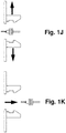
- Fig. 1A to 1K show the basic sequence followed during the assembly of a seal 1 or cable tunnel (see also the flowcharts presented on Fig. 6A to 6C and 7A to 7C ).
- the seal 1 is slipped onto a holding arbor 2.
- the holding arbor 2 is moved downward, for example into the area of a feeder rail (not shown), in which the seals 1 are brought in.
- the holding arbor 2 picking up the seal 1 then returns to its original position, as shown on Fig. 1B .
- the holding arbor 2 is pushed into an assembly pipe 11, and the seal 1 is slipped onto the assembly pipe 11, as depicted on Fig. 1C and 1D .
- the holding arbor 2 is taken out of the assembly pipe 11, the assembly pipe 11 is swiveled by 90°, and then pushed along with the seal 1 into a seal chamber 12.
- the seal chamber 12 is then closed as depicted on Fig. 1F .
- a cable or wire 13 is pushed into the assembly pipe 11 (see also Fig. 1H ). As depicted, this cable or wire may have a stripped end.
- the assembly pipe 11 is pulled out of the seal chamber 12, leaving the seal 1 behind on the wire/cable 13 in the seal chamber 12.
- the seal chamber 12 is opened, after which the wire/cable 13 with the seal 1 is taken out of the latter, as depicted on Fig. 1K .
- Fig. 2 presents a first exemplary embodiment of a two-part holding arbor 2 according to the invention with a seal 1 correctly oriented on the holding arbor 2 and a perpendicularly aligned primary axis 4, in a side view to the left, and a sectional view to the right.
- a force and/or pressure transducer 3 is situated between two crimping jaws, and is pre-tensioned by two screws with counter nuts secured to the crimping jaws.
- the two lateral expansions of the lower part 7 and upper part 6 of the holding arbor 2 lying opposite as well as the force and/or pressure transducer 3 comprise the interface 5 between the parts 6, 7 of the holding arbor 2 used to relay the force to be acquired.
- the electrical contacts on either side of the sensor element 9 are routed to the outside as flat conductors 10 adhesively bonded to a suitable insulating carrier material, preferably paper or a film.
- Fig. 3 illustrates another exemplary embodiment of the holding arbor 2, which is distinguished from Fig. 2 in that a two-part bushing 8 partially encapsulates the sensor.
- the bushing 8 is provided to better protect the force transducer 3, and simultaneously assumes the function of pre-tensioning the force and/or pressure transducer 3.
- Fig. 4 provides a particularly clear view of the details of the holding arbor 2 presented on Fig.3
- Fig. 5B magnifies those of the interface 5 by showing a section F, which is defined in the total view Fig. 5A of the holding arbor 2.
- Fig. 4 gives an inclined view of the overall holding arbor 2 according to Fig. 3
- Fig. 5B shows a sectional view of its partially encapsulated measuring cell.
- the two adjacent arbor parts 6, 7 situated coaxially relative to the shared primary axis 4 are laterally expanded at their opposing ends, and non-positively accommodate a force and/or pressure transducer 3 in between.
- the interface 5 in the holding arbor 2 comprised of the aforesaid end parts of the arbor and the force and/or pressure transducer 3 is held in place by a two-part bushing 8 that can be screwed into itself.
- This bushing 8 may be used to mechanically pre-tension the force and/or pressure transducer 3 by screwing together the two bushing parts, with the effect of reducing the length of the entire bushing 8.
- the arbor part 7 on the accommodation side is spaced laterally apart from the part of the bushing 8 on the accommodation side so as to prevent the holding arbor 2 from becoming laterally jammed.
- the force and/or pressure transducer 3 is preferably designed as a piezoelectric sensor, but may also be a capacitive sensor.
- the sensor element 9 configured as a piezo disk or in the form of a plate capacitor is contacted on both sides by flat conductors 10 as in the exemplary embodiment according to Fig. 2 , which are adhesively bonded in the same way to a suitable insulating carrier material, preferably paper or a film.
- the force and/or pressure measurements may also make use of strain gauges, which may be calibrated.
- the pressure transducer 3 may be embodied as a measuring box or load cell having strain gauges, or the structural design of the measuring cell can alternatively be adapted as required relative to the one on Fig. 2 to 5B in another way.
- a counter is provided and initialized at the beginning. Then a seal 1, the first or a next one, is fed into the pick up position, and its presence in this position is checked by a photoelectric barrier. In case this check is negative, a next seal is fed into the pick up position, but only if the numbers of such negative results does not supersede a certain number of maximum attempts to feed, pick up and transfer a seal 1. If said number was superseded the seal fitting is put away, an error message is output and the process will only be restarted after elimination of the fault, confirming the error and restarting the seal fitting by the operator.
- the assembly pipe 11 is pivoted toward the seal chamber, inserted into the open seal chamber, which is closed then.
- a ready message is then sent to the cable processing plant, which then inserts the cable in the assembly pipe in the seal chamber.
- a process signal of the cable processing plant starts now the seal fitting.
- the assembly pipe is withdrawn from the closed seal chamber, to pull the accommodated seal onto the cable.
- the seal chamber is opened and the seal fitted cable is swiveled out therefrom.
- a check is basically performed to determine whether a seal 1 is present on the holding arbor 2 or assembly pipe 11, but no test is run to determine whether the latter is undamaged too. Therefore, it cannot be precluded that an unusable cable arrangement will be produced.
- the inquiry W>Wmin,ref? can also be used to check whether a seal 1 was even slipped onto the holding arbor 2 at all.
- a seal 1 the first or a next one, is fed into the pick up position, and its presence in this position is checked by a photoelectric barrier. In case this check is negative, a next seal is fed into the pick up position.
- This movement is accompanied by triggering the chain of steps stopping the seal fitting, outputting an error message, elimination of the fault, confirming the error and restarting the seal fitting.
- a positive check leads to an upward stroke of the holding arbor 2 and the returning to the pick up position, followed by processing a signal of the cable processing plant to release loading of the seal chamber. Thereafter, the assembly pipe 11 is pivoted toward the seal chamber, inserted into the open seal chamber, which is closed then.
- Fig. 6A now presents exemplary force-path progressions F over s given the proper accommodation of a seal 1 (curve A), given the destruction of the seal 1 (curve B), given a missing seal 1 (curve C) and given a seal 1 that is only crimped by the holding arbor 2 (curve D).
- the path s here relates to the path traversed by the seal 1 on the holding arbor 2. This need not be a continuous motion, as the seal 1 can also be slipped onto the holding arbor 2 in several steps as well.
- Fig. 6A presents exemplary force-path progressions for the procedural steps shown on Fig. 1A to 1C .
- a strong rise in force F may come about if the seal 1 is incorrectly accommodated, which abruptly drops again at a certain point in time, specifically when the holding arbor 2 punches through the wall of the seal 1, thereby destroying it. After punching through, the force F stays more or less constant, but at a higher level than for curve A, since the seal 1 the case of curve B is not slipped over the holding arbor 2 by way of a prefabricated hole, but rather via a hole created by the latter.
- the force increases very sharply given just a slight displacement path (or path of penetration by the holding arbor 2 into the seal 1 in this case), as represented by curve D.
- the latter may be stopped or moved back.
- curves A to D may now be used to detect the correct sequence for assembling a seal 1 on a cable or wire 13.
- a corridor or range (see dashed lines in Fig. 6A ) may be provided within which the curve A is allowed to run. If the actually ascertained force progression is above this corridor, a seal 1 was in all likelihood punched through or crimped, while if it lies below, no seal 1 was in all likelihood accommodated at all.
- the corridor or range shown in Fig. 6A may be arranged symmetrically around a mean curve (nominal curve) of a set of curves A. If said nominal curve drifts because of e.g. sensor drift, then said corridor or range is shifted too, Otherwise, crimps with good quality could mistakenly be qualified as bad.
- Fig. 6B shows the exemplary curve A of Fig. 6A and the work W, which is needed to perform crimping.
- the actual value for the work W can be compared with a desired value of the same for qualifying the crimping process. Similar to the corridor shown in Fig. 6A an upper threshold value and a lower threshold value may be defined, between which the actual value shall be.
- F over s force-path characteristic
- P over s pressure-path characteristic
- a seal 1 has been slipped on incorrectly, the production sequence shown on Fig. 1A to 1K may be terminated or interrupted at a suitable point.
- a crimped seal 1 that stayed behind on a feeder can be blown down from the feeder (see Fig. 7 ) or conveyed into a waste container 15 by means of a slider 16 (see Fig. 8 ).
- a seal 1 that was slipped onto the holding arbor 2 but was also damaged can be stripped from the holding arbor 2, for example during the reverse stroke of the holding arbor 2 ( Fig. 1B ), by means of an inserted stripper 17 ( Fig. 9 ) or inwardly swiveled stripper 18 ( Figs.
- the holding arbor 2 can be positioned over a waste container 15 to this end ( Figs 9 and 10 ).
- the seal 1 it is also conceivable for the seal 1 to be stripped on the feeder, and blown or pushed down from there like a seal 1 that got left behind (see Fig. 11 in particular in combination with Fig. 8 and/or Fig. 9 ).
- seals 1 into a waste container 15 are not a necessary condition. It is also conceivable that seals 1, which are not damaged are fed back to the production process, that is, there is another try to mount said seal 1. In particular this applies to the cases shown in Figs. 7 and 8 . To this end, seals 1 in good condition may be fed back to the production process, whereas bad seals 1 are disposed.
- the curves in Fig. 6A may be the base for that decision. If a force-path progressions F over s according to curve C is detected, a seal 1 (if there is any) may be fed back, whereas seals 1 are disposed, when a force-path progressions F over s according to curve B is detected. If a force-path progressions F over s according to curve D is detected, the seal 1 may be disposed for safety reasons or it is inspected in another way (e.g. visually) to decide whether it is in good or bad condition.
- Fig. 12 shows further variants and details of the inventive device.
- a pinhole diaphragm 19 is shown, which facilitates picking up of the seal 1 by the holding arbor 2, that can protrude through the pinhole diaphragm 19.
- a conveyor 20 is provided, which feeds seals 1 into an pick up position provided for accommodation via a transfer unit.
- evaluation electronics 21 are shown, which are connected to the holding arbor 2, concretely to its sensor element 8.
- a computer 22 is operationally connected to the evaluation electronics 21 in Fig. 1s so as to execute evaluation algorithms for the decisions as to whether seals may be processed or must be separated out.
Landscapes
- Chemical & Material Sciences (AREA)
- Analytical Chemistry (AREA)
- Engineering & Computer Science (AREA)
- Manufacturing & Machinery (AREA)
- Physics & Mathematics (AREA)
- General Physics & Mathematics (AREA)
- Microelectronics & Electronic Packaging (AREA)
- Examining Or Testing Airtightness (AREA)
- Manufacturing Of Electrical Connectors (AREA)
- Automatic Assembly (AREA)
Description
- The invention relates to a method for fitting cables with cable sleeves according to the preamble to claim 1, and to a seal fitting station according to the preamble to claim 4.
- A cable sleeve or "seal" is a complex plastic ring with several radial expansions ("shoulders"), which is slipped over an insulated cable harness, and seals the cable harness (e.g., a multi-core strand) or each individual cable of a cable harness with one or more crimped-on contacts against the penetration of liquid and contaminants.
- The process of mounting seals on cables in cable processing plants is today fully automated. In particular, there are also largely autonomous and compact processing stations with standardized interfaces, that execute the process of fitting cables with seals as part of a multistage, fully automated cable processing routine (e.g., stripping before and crimping after seal assembly), and make it possible to modularly expand all automated cable processors available on the market with an additional seal fitting station.
- The main processing steps involved in the typical machining of seals include: a.) conveying them out of a storage container onto a conveyor (conveyor belt, conveyor rail); b.) separating and orienting them on the conveyor; c.) accommodating them or - in other words - picking them up on a holding arbor from the conveyor; d) slipping them onto an assembly pipe; e) guiding them on the assembly pipe over the cable to be fitted; f) and, stripping them from the assembly pipe onto the cable.
-
EP 0410416 A2 discloses a method similar to the preamble ofclaim 1, where a leading bung seal in a magazine is picked up by a bung seal transfer clamp and is positioned between a bung seal receptacle and a bung seal transfer device, which are axially aligned. A bung seal expansion pin is advanced to drive the leading bung seal into the bung seal receptacle, to force it against a resilient grommet therein, and to extend through the bung seal so as to expand it. A bung seal expansion sleeve surrounding the expansion pin is then advanced further to expand the bung seal and the pin is withdrawn leaving the bung seal secured to the expansion sleeve by its own resilience. A lead is then inserted into the expansion sleeve, and the expansion sleeve is then withdrawn, leaving the seal secured to the lead, by its own resilience, after which the bung seal receptacle is opened and the lead with the bung seal thereon is removed to a station at which an electrical terminal is crimped to the lead and to the bung seal. - In order to avoid processing mistakes in this process chain to the greatest extent possible, fault-prone subprocesses are often subjected to fully automated monitoring while processing the seals.
- Prior art discloses, in particular, optical monitoring devices (e.g., photoelectric barriers or digital cameras with evaluation electronics) for achieving this objective. For example, in seal stations readily available on the market, a photoelectric barrier checks for the presence of a seal in the position where it is accommodated or picked up via the conveyor at a specific point in time or during a specific period within the work cycle time interval. If no seal is detected in the pick up position, the fitting process is stopped.
- Seal orientation is also important for correctly picking up of a seal via the conveyor, and hence is sometimes monitored.
- In the absence of such monitoring, any process errors that arise in this process stage may lead to difficulties as subsequent procedural steps run their course, or yield a seal-fitted cable that does not satisfy the stringent quality requirements set forth in the relevant standards as the end product of the seal fitting process or entire cable processing routine. A cable faultily processed in this way usually ends up as scrap. This not only represents a cost factor, but may also be associated with logistical problems.
- The orientation of a seal is understood as the alignment of its axis running centrally through its middle tunnel. This axial direction is adjusted in a seal while conveying it into the pick up position in such a way that, in the pick up positionpick up position, it is preferably parallel to the main axis of the holding arbor provided for picking up the seal via the conveyor. During proper operation, the seal is oriented and positioned on the conveyor in such a way that the holding arbor punches centrally through the seal during a forward stroke along the tunnel/bore axis of the seal in order to accommodate the seal.
- In contrast, the term "orienting a seal on the holding arbor" as used in the following assesses the orientation of a seal generally defined above. If the seal is centrally punched through by the holding arbor along the tunnel axis of the seal during its forward stroke, the seal orientation on the holding arbor is regarded as "correct", otherwise as "incorrect".
- Assuming that a seal is present in the pick up position, primarily the following fault scenarios are possible while picking up a seal, which lead to an erroneous orientation of the seal on the holding arbor in the sense just established:
- 1) The holding arbor collides with the seal from outside, and maximally penetrates far enough into the jacket body of the seal that the seal does not get caught in the holding arbor. The seal is instead only crimped from outside from the effect exerted by the forward stroke of the holding arbor, with any potential damage only being done to the exterior. In the process, it is
- a) either jammed by the holding arbor and remains in the accommodation area of the conveyor, or
- b) forced or catapulted out of the pick up positionpick up position by the holding arbor and lost, possibly disrupting the process at another location.
- 2) During its forward stroke, the holding arbor at least partially penetrates far enough into the jacket body of the seal that the seal gets caught in the holding arbor. A distinction must here be made between the two cases, in that the holding arbor:
- a) either penetrates into the incorrectly oriented seal from outside, or,
- b) after partially introduced into the tunnel of the seal, penetrates or punches through the jacket body of the latter from inside.
- In all of these errors, the seal already may not be processable further in light of the high probability that the sealing lips of the seal arranged on the inside have become damaged, or the seal no longer satisfies the stringent tightness requirements due to exterior damages. Preventing damages is a common task in most technical fields, as can be seen from e.g.
US 2003/079342 A1 . This document discloses a wire manipulator which includes a body with a jack for moving clamping arms to hold a wire extremity insert the extremity in an alveolus of a connector. The insertion force is sensed by a force sensor in the clamping arms and is compared with a reference force to stop the insertion process to avoid damage to the wire, the connector and the manipulator. - The mentioned procedural errors stem from a deficiently aligned seal in the pick up position on the conveyor. Operators have until now subjected the seal accommodation to occasional visual monitoring so as to be able to respond as directly as possible thereto, even though having to interrupt the process. This personal monitoring Is expensive and unproductive.
- Another monitoring procedure involving a photoelectric barrier according to prior art checks the seal in the pick up position, and is associated with other disadvantages.
- While the photoelectric barrier is sufficient for monitoring the presence of a seal in the pick up position, it provides no information about the correct positioning (location) and orientation of the seal. In general, several photoelectric barriers are needed to monitor the correct positioning and orientation. However, this variant is technically complex, inelegant, and of less robustness. It also delays the overall process of fitting cables with varying seals, since additional setup time must be expended to adjust the position of the photoelectric barriers during each switch between two different seal types.
- Monitoring with a digital camera leads to digital snapshots, and analyzing the relevant details of the latter is a time-consuming and computationally intensive process. The wide variety of possible shapes for the seals, for example in terms of their cross section, further raises the complexity of the monitoring camera test algorithms to be processed by the evaluation electronics.
- In order to meet the enhanced quality requirements placed on the seal fitting, but also to increase sealing station productivity, it is proving increasingly necessary to shift the monitoring of pick up position to the process of seal accommodation, at least to the critical phases thereof, and to perform the latter within narrow time intervals, that is, to process ever increasing quantities of test data. The software required for this purpose greatly drives up the price in optical monitoring processes.
- However, the time requirements that a high processing clock places on monitoring must be satisfied nonetheless. While this condition poses no problem in inertia-free optical methods involving electronic evaluation, the mechanical steps taken to separate out defective seals should also diminish the work cycle to the least possible extent.
- In order to correct processing errors during seal fitting once they have been detected, an incorrectly fitted cable had previously been sorted out after the fact and destroyed. This method reduces the productivity of the fitting system relative to the goal of having the correction take place as proximate in time to the error as possible, and still in the same procedural step whenever possible.
- An object of the present invention arises from the above disadvantages associated with the conventional monitoring of seal orientation, and specifically involves providing a simple method and a device for fitting a cable with seals, in which the orientation of seals on the holding arbor may be monitored more cheaply in comparison to prior art. The goal of this simple monitoring routine is to detect seals with a faulty orientation on the holding arbor as soon as possible, so that the process of separating out a faulty seal may take place already before the seal is assembled on the cable.
- This object may be achieved according to the invention as described in
claim 1 by using a electromechanical method and a device according toclaim 4 for implementing this method. - The method according to the invention encompasses two procedural components: One of these procedural components involves measuring the mechanical force and/or mechanical pressure of the holding arbor on the seal along the accommodation path on which the seal is to be accommodated by the holding arbor during a forward stroke of the holding arbor or during the time that elapses in the process (i.e., the force and/or pressure as a function of the path provided for accommodation or time required to traverse said path), followed by the processing of measured data.
- The measurements or recordings are here evaluated fast enough that, given a negative test result, a seal deemed to be unusable may be separated out, and the holding arbor may be reversed in a timely manner as additionally required in this case.
- The force at which the holding arbor is punched into the seal is a process-inherent force, so that the force or pressure measurement according to the invention and its evaluation accompany the process.
- One essential component of the evaluation involves the comparison of force-path value pairs or pressure-path value pairs or force-time value pairs or pressure-time value pairs to reference value pairs, or of variables derived from the measured value pairs to corresponding reference variables. According to the invention, this comparison is the criterion for deciding on whether to further process a tested seal.
- The above measurements are performed in various configurations of the invention using piezoelectric or capacitive sensors, but also strain gauges. A combination of these sensor types is also conceivable.
- The second procedural component encompasses the potential elimination of seals deemed to be fault-prone. If necessary, this procedural step takes place by removing seals to be categorized as scrap from the holding arbor during the reverse stroke of the holding arbor and/or disposing them via a disposal system (e.g., by means of a discharge nozzle or drop shaft) after this reverse stroke has progressed sufficiently, wherein the holding arbor is reversed for as seamless a transition as possible to the next seal accommodation, as already mentioned.
- Therefore, the procedural steps may be briefly summarized as follows:
- According to the invention, the seal is "picked up" once it has been transported to the pick up position by the conveyor and pre-oriented in the pick up position. The force expended and/or pressure expended is here measured, recorded and further processed. The seal has a specific orientation in the pick up position. If this orientation coincides with the primary axis of the holding arbor and the seal is in the envisaged pick up position prior to its accommodation, the position and orientation of the seal on the holding arbor are hence correct, that is, the direction of its central tunnel/bore runs coaxially to the primary axis of the holding arbor. The force and/or pressure-path measuring unit then reports an uncritical force and/or pressure-path progression. Otherwise, that is, given a faulty orientation of the seal on the holding arbor, the force and/or pressure-path progressions exit the tolerance range, and the seal is separated out. The same set of circumstances applies with respect to the measured force and/or pressure-time progressions.
- A device according to the invention disclosed for implementing the method according to the invention comprises the transfer unit expanded in relation to prior art to include a force and/or pressure-measuring device. In a configuration reflecting prior art, this transfer unit is a machine unit of the seal station, which is designed to execute both an up and down motion as well as a swiveling motion. Consequently, it encompasses two separate pneumatic cylinders, specifically a lifting and positioning cylinder, along with the holding arbor as the most important component.
- The transfer unit is provided for the automatic process of picking up a seal via the conveyor until the seal is slipped onto an assembly pipe, a process referred to as a transfer process, a possible embodiment variant of which will be described below. The assembly pipe rests on a multipart arrangement of horizontally traversable carriages (preferably an upper and lower carriage). In order to provide a complete, overall illustration of function, we will now elaborate a bit further, and briefly describe below the remaining functions of the holding arbor as a constituent of the transfer unit within the framework of the transfer process.
- After a seal has been accommodated by the holding arbor, the transfer unit is swiveled by the positioning cylinder in such a way that the holding arbor assumes a position in front of a pinhole diaphragm and coaxial to its hole axis. This pinhole diaphragm consists of a preferably two-part wall made out of plastic, wherein the holding arbor is pushed through the hole therein during the ensuing forward stroke powered by the lifting cylinder. However, since the seal resting on the holding arbor strikes the diaphragm in the process, this forward stroke on the holding arbor pushes backward. As the forward stroke of the holding arbor continues, a pipe coaxially enveloping the arbor in its rear section thereafter opens the pinhole diaphragm so wide that the seal resting on the holding arbor now can also pass through the diaphragm. Finally, the holding arbor is introduced into the aforementioned assembly pipe positioned coaxially opposite, thereby slipping the seal onto this assembly pipe. Later in the processing sequence, the assembly pipe is directly engaged in the fitting of the cable with the seal, and hence comprises part of the actual seal fitting device.
- The holding arbor consists of two or more parts in two disclosed embodiment variants according to the invention, and exhibits force and/or pressure measuring devices in proximity to the interfaces of its adjacent individual parts, which transmit their measuring signals from the conveyor or immediately thereafter to evaluation electronics in the process of picking up the seal.
- According to the invention, however, viewed in the direction of the forward stroke of the holding arbor, these force and/or pressure measuring devices may also be located behind the holding arbor in or parallel to the action line of the accommodation force and non-positively relative to parts of the holding arbor when using a one- or multipart arbor.
- The evaluation electronics are used to evaluate the recorded force and/or pressure gradients, so as to decide whether or not to further process the tested seal, if necessary in tandem with a higher-level controller in order to reverse the holding arbor if the tested seal is separated out.
- Some of the numerous advantages to the method according to the invention and device according to the invention for implementing this method will now be explained below.
- It is especially advantageous to metrologically acquire entire progressions or partial progressions of measured variables, specifically the force-path or pressure-path progressions or the force-time or pressure-time progressions. This makes it possible to derive more informative comparative variables from the mentioned quantity of value pairs for deciding whether to continue processing a currently tested seal. In this sense, for example, the integral for the overall or partial progression of accommodation force to be expended by the holding arbor along the accommodation path can be used as a practical criterion for deciding whether a seal is correctly oriented on the holding arbor. This integral represents a scalar measure for the mechanical work to be performed by the holding arbor for the overall accommodation process or a partial accommodation process.
- This integral varies as a function of how the seal is acquired by the holding arbor during its forward stroke, and as a function of the material properties of the seal. The required case differentiation plus numerical integration is easily mastered by means of modern evaluation electronics.
- One possible approach toward ordering the magnitude of work expended by the holding arbor for a common seal material is geared toward the error scenarios mentioned above during the accommodation of the seal via the conveyor:
- If the holding arbor advances into an empty space during its forward stroke because no seal is present in the pick up position, the work to be performed by the holding arbor will naturally be at the lowest level.
- The next highest level of work expended arises if the seal correctly punches centrally through the holding arbor. In this case, the holding arbor must essentially perform the corresponding work needed to overcome the frictional force component in the direction opposite the forward stroke of the holding arbor. As in itself known, this frictional force, which undergoes a slight, progressive rise corresponding to the conicity of at least portions of the holding arbor, must be surmounted to establish the preconditions for widening the seal in the next procedural step, which specifically involves slipping the seal onto the assembly pipe by introducing the holding arbor into this assembly pipe.
- On the presumption of often used seal materials, even more mechanical work must be expended by the holding arbor if the holding arbor punches through the jacket of the seal from outside or inside.
- Finally, the holding arbor must expend the most amount of work if the seal is only crimped, that is, if it resists penetration by the holding arbor due to a correspondingly higher resilience of its material, and then becomes jammed in the accommodation area by the holding arbor.
- Comprehensive test series based on this simple qualitative model have resulted in reference progressions, which can be used as a standard of comparison to arrive at an unambiguous decision for different cases of acquiring the seal by the holding arbor and various seal materials and seal forms as to whether the seal acquired by the holding arbor can be further processed or must be separated out. Suitable evaluation algorithms for this purpose may be smoothly executed by a computer, in particular a fast microcontroller, at least at a rate fast enough to separate out a seal deemed to be unusable and reverse the holding arbor as required in this instance given a negative test result, in a timely fashion.
- Another advantage to the method according to the invention is that separating out defectively oriented seals delays the fitting process as little as possible, as will be described below.
- Let us first examine a case in which, given a faulty accommodation or none at all, the holding arbor maximally penetrates into the seal to a point where the seal does not yet get caught on the holding arbor. As already mentioned, this case is present when, for example, the seal is only crimped by the holding arbor, possibly damaged on the inside and/or outside, and remains in the accommodation area (case 1a). If the force-path measurement or pressure-path measurement or corresponding force-time measurement or pressure-time measurement detects a faulty orientation of this kind, the holding arbor, which initially executes a reverse stroke given a flawless seal accommodation, so as to remove the accommodated and widened seal onto the accommodation pipe at the end of the next forward stroke by penetrating into the accommodation pipe, is reversed according to the invention in such a way that its reverse stroke is followed by a forward stroke for picking up the next seal. By using the time of the reverse stroke of the holding arbor according to the invention to remove the only-crimped seal remaining in the accommodation area from the accommodation area by means of a disposal device, for example a compressed air nozzle or drop shaft, the delay of the fitting process caused by separating out this seal is confined to the narrowest possible limits.
- In another important error that has also already been mentioned, the seal is faultily accommodated because the holding arbor fails to move parallel to the central tunnel axis of the seal, and the jacket body of the seal is punched through from the inside out. According to the invention, a stripping device initially intervenes during the reverse stroke of the holding arbor, stripping the faultily accommodated seal from the holding arbor. As the reverse stroke continues, the punctured seal is removed from the accommodation area as before by means of a disposal device, and the correspondingly reversed holding arbor starts its ensuing forward stroke to accommodate the next seal that had been pushed forward.
- Another important advantage has to do with the fact that the force and/or pressure measurement is invariant as to form. When using a digital camera, optically detecting a failed pre-orientation of a seal requires that the position of the photographed seal be analyzed relative to its environment on the one hand, and that the form of the photographed seal be taken into account on the other. Seals are today being used in a plurality of different configurations for a wide variety of purposes. The electromechanical test eliminates the need for the aforementioned outlay associated with the use of a digital camera, since the decision as to whether to further process the seal after the accommodation motion of the holding arbor can only be made based on the force-path or pressure-path progressions or the force-time or pressure-time progressions, that is, regardless of the angle assumed, for example, by the tunnel axis of the acquired seal relative to the primary axis of the holding arbor, or whether the cross section of the seal is circular or rectangular, for example.
- As opposed to the (in particular optical) methods known in the art, which only check the seal externally and not as a whole, the method according to the example makes it possible to detect internal damages (i.e., damage to the inner sealing lips, for example) to a seal.
- In addition, in particular piezoelectric force or pressure measurements are much more robust than optical test methods.
- Finally, the clearly lower price of the electromechanical test method according to the invention by comparison to conventional optical test methods is advantageous, since it lowers the price of the entire seal station.
- An advantage to the transfer unit according to the invention lies first and foremost in the fact that this transfer unit enhances the safety of the fitted seals. The transfer unit according to the invention automatically prevents damaged seals from being slipped onto cable ends and producing scrap cable in this way, because seals to be classified as scrap goods are already separated out after the forward stroke of the holding arbor for picking up the seal has completely run its course. While prior art must rely upon a costly optical device (usually a digital camera) to check the orientation of the seal, the electromechanical monitoring device according to the invention robustly and cost-effectively yields a decision as to whether a checked seal will be further processed or not.
- As already mentioned, as an alternative to the described force-path and/or pressure-path or force-time and/or pressure-time measurement, the invention also makes it possible to arrange the used force transducer outside of the holding arbor, specifically behind the holding arbor in or parallel to the action line of the accommodation force and non-positively relative to parts of the holding arbor, as viewed in the direction of the forward stroke of the holding arbor. This alternative test setup brings with it some additional advantages in terms of handling the transfer device and saving on costs:
- All holding arbors of a conventional arbor set may be retrofitted with just a single external sensor to make them capable of measuring force or pressure.
- No connection lines have to be hooked up while changing the holding arbors, since they remain connected permanently.
- The sensor can be better protected when built in.
- The method according to the invention and the device according to the invention for its implementation will now be described based on several exemplary embodiments.
- Shown in:
-
Fig. 1A to 1K is the basic sequence followed during the assembly of a seal or cable tunnel, -
Fig. 2 is a first exemplary embodiment of the holding arbor according to the invention in a schematic sectional view A-A with the seal correctly oriented on the holding arbor, -
Fig. 3 is a sectional view D-D of another exemplary embodiment according to the invention for the holding arbor, -
Fig. 4 is an inclined view of the holding arbor according to the invention perFig. 3 , -
Fig. 5A is a sectional view E-E depicting a section F of a holding arbor according toFig.3 , representing an interface at the boundary between two parts of this holding arbor, -
Fig. 5B is a more detailed view of the section F shown inFig. 5A , -
Fig. 6A shows exemplary force-path progressions during the accommodation of a seal via the holding arbor, -
Fig. 6B shows an exemplary force-path progression during the accommodation of a seal via the holding arbor and the work needed therefore, -
Fig. 7 shows a seal, which is badly oriented on the conveyor/feeder and blown into a waste container by means of compressed air, -
Fig. 8 shows a seal, which is badly oriented on the conveyor/feeder and moved into a waste container by means of a slider, -
Fig. 9 shows a seal, which is badly oriented on the holding arbor and stripped from the same into a waste container by means of shiftable stripper, -
Fig. 10 shows a seal, which is badly oriented on the holding arbor and stripped from the same into a waste container by means of pivotable stripper, -
Fig. 11 shows a seal, which is badly oriented on the holding arbor and stripped from the same onto the conveyor/feeder by means of pivotable stripper and then blown into a waste container by means of compressed air, and, -
Fig. 12 shows a pinhole diaphragm, a conveyor and evaluation electronics for the inventive device. -
Fig. 1A to 1K show the basic sequence followed during the assembly of aseal 1 or cable tunnel (see also the flowcharts presented onFig. 6A to 6C and7A to 7C ). In a first section depicted onFig. 1A , theseal 1 is slipped onto a holdingarbor 2. To this end, the holdingarbor 2 is moved downward, for example into the area of a feeder rail (not shown), in which theseals 1 are brought in. The holdingarbor 2 picking up theseal 1 then returns to its original position, as shown onFig. 1B . In another step, the holdingarbor 2 is pushed into anassembly pipe 11, and theseal 1 is slipped onto theassembly pipe 11, as depicted onFig. 1C and 1D . In a step shown onFig. 1E , the holdingarbor 2 is taken out of theassembly pipe 11, theassembly pipe 11 is swiveled by 90°, and then pushed along with theseal 1 into aseal chamber 12. Theseal chamber 12 is then closed as depicted onFig. 1F . In a step shown onFig. 1G , a cable orwire 13 is pushed into the assembly pipe 11 (see alsoFig. 1H ). As depicted, this cable or wire may have a stripped end. In another step depicted onFig. 11 , theassembly pipe 11 is pulled out of theseal chamber 12, leaving theseal 1 behind on the wire/cable 13 in theseal chamber 12. In a step shown onFig. 1J , theseal chamber 12 is opened, after which the wire/cable 13 with theseal 1 is taken out of the latter, as depicted onFig. 1K . - Of course, the course of action shown is only intended to provide an exemplary illustration for the assembly of a
seal 1 on a wire/cable 13. -
Fig. 2 presents a first exemplary embodiment of a two-part holding arbor 2 according to the invention with aseal 1 correctly oriented on the holdingarbor 2 and a perpendicularly alignedprimary axis 4, in a side view to the left, and a sectional view to the right. - In the arrangement depicted, a force and/or
pressure transducer 3 is situated between two crimping jaws, and is pre-tensioned by two screws with counter nuts secured to the crimping jaws. The two lateral expansions of thelower part 7 and upper part 6 of the holdingarbor 2 lying opposite as well as the force and/orpressure transducer 3 comprise theinterface 5 between theparts 6, 7 of the holdingarbor 2 used to relay the force to be acquired. The electrical contacts on either side of the sensor element 9 are routed to the outside asflat conductors 10 adhesively bonded to a suitable insulating carrier material, preferably paper or a film. -
Fig. 3 illustrates another exemplary embodiment of the holdingarbor 2, which is distinguished fromFig. 2 in that a two-part bushing 8 partially encapsulates the sensor. Thebushing 8 is provided to better protect theforce transducer 3, and simultaneously assumes the function of pre-tensioning the force and/orpressure transducer 3.Fig. 4 provides a particularly clear view of the details of the holdingarbor 2 presented onFig.3 , whileFig. 5B magnifies those of theinterface 5 by showing a section F, which is defined in the total viewFig. 5A of the holdingarbor 2. -
Fig. 4 gives an inclined view of theoverall holding arbor 2 according toFig. 3 , whileFig. 5B shows a sectional view of its partially encapsulated measuring cell. As already mentioned, the twoadjacent arbor parts 6, 7 situated coaxially relative to the sharedprimary axis 4 are laterally expanded at their opposing ends, and non-positively accommodate a force and/orpressure transducer 3 in between. Theinterface 5 in the holdingarbor 2 comprised of the aforesaid end parts of the arbor and the force and/orpressure transducer 3 is held in place by a two-part bushing 8 that can be screwed into itself. Thisbushing 8 may be used to mechanically pre-tension the force and/orpressure transducer 3 by screwing together the two bushing parts, with the effect of reducing the length of theentire bushing 8. Thearbor part 7 on the accommodation side is spaced laterally apart from the part of thebushing 8 on the accommodation side so as to prevent the holdingarbor 2 from becoming laterally jammed. - The force and/or
pressure transducer 3 is preferably designed as a piezoelectric sensor, but may also be a capacitive sensor. In both cases, the sensor element 9 configured as a piezo disk or in the form of a plate capacitor is contacted on both sides byflat conductors 10 as in the exemplary embodiment according toFig. 2 , which are adhesively bonded in the same way to a suitable insulating carrier material, preferably paper or a film. - Finally, the force and/or pressure measurements may also make use of strain gauges, which may be calibrated. In this case, however, the
pressure transducer 3 may be embodied as a measuring box or load cell having strain gauges, or the structural design of the measuring cell can alternatively be adapted as required relative to the one onFig. 2 to 5B in another way. - In the following, a prior art method for carrying out the steps presented on
Fig. 1A to 1K is explained. A counter is provided and initialized at the beginning. Then aseal 1, the first or a next one, is fed into the pick up position, and its presence in this position is checked by a photoelectric barrier. In case this check is negative, a next seal is fed into the pick up position, but only if the numbers of such negative results does not supersede a certain number of maximum attempts to feed, pick up and transfer aseal 1. If said number was superseded the seal fitting is put away, an error message is output and the process will only be restarted after elimination of the fault, confirming the error and restarting the seal fitting by the operator. With a seal recognized as in position, however, the downward stroke of the holdingarbor 2 and then an upward stroke is effected to pick up theseal 1. The holdingarbor 2 is now moved to the perpendicularly disposedassembly pipe 11, where follows a downward stroke of the holdingarbor 2 by automatically actuated expansion jaws with transfer to theassembly pipe 11. Of course, the presence of aseal 1 is again checked also on theassembly pipe 11. In case this check is negative, an upward stroke of the holdingarbor 2 is effected and it is returned to the pick up position and the counter is incremented by 1. A positive check, too, leads to an upward stroke of the holdingarbor 2 and the returning to the pick up position, but without incrementing the counter. Instead, a signal of the cable processing plant is processed to release loading of the seal chamber. - Thereafter, the
assembly pipe 11 is pivoted toward the seal chamber, inserted into the open seal chamber, which is closed then. A ready message is then sent to the cable processing plant, which then inserts the cable in the assembly pipe in the seal chamber. A process signal of the cable processing plant starts now the seal fitting. In a next step, the assembly pipe is withdrawn from the closed seal chamber, to pull the accommodated seal onto the cable. Before the starting the above process again, the seal chamber is opened and the seal fitted cable is swiveled out therefrom. As may readily be gleaned from the chart, a check is basically performed to determine whether aseal 1 is present on the holdingarbor 2 orassembly pipe 11, but no test is run to determine whether the latter is undamaged too. Therefore, it cannot be precluded that an unusable cable arrangement will be produced. - According to an improved method explained below the inquiries W<=Wmax,ref? (see also
Fig. 6B ) ensure that only thoseseals 1 are mounted on the wire/cable 13 that were not damaged by the holdingarbor 2. The inquiry W>Wmin,ref? (see alsoFig. 6B ) can also be used to check whether aseal 1 was even slipped onto the holdingarbor 2 at all. Again, for this improved method, aseal 1, the first or a next one, is fed into the pick up position, and its presence in this position is checked by a photoelectric barrier. In case this check is negative, a next seal is fed into the pick up position. The condition for stopping the seal fitting, outputting an error message, elimination of the fault, confirming the error and restarting the seal fitting by the operator will be deducted from a later step of the process. With a seal recognized as in position, however, the downward stroke of the holdingarbor 2 is effected, including the electromechanical test, which is evaluated at the end of the stroke (e.g. taking into account the work W). If this work W is below a given minimum reference value Wmin,ref the holdingarbor 2 is reversed into an upward stroke and returned to the pick up position. In addition, the chain of steps stopping the seal fitting, outputting an error message, elimination of the fault, confirming the error and restarting the seal fitting is triggered. If the mentioned minimum reference value is exceeded and a maximum reference value Wmax,ref is exceeded, too, this test result is stored. If the measured work W lies between both reference values, this result is stored, too, and then an upward stroke of the holdingarbor 2 is effected, with the effect of picking up theseal 1 correctly. The holdingarbor 2 is now moved to the perpendicularly disposedassembly pipe 11, where follows a downward stroke of the holdingarbor 2 by automatically actuated expansion jaws with transfer to theassembly pipe 11. Of course, the presence of aseal 1 is again checked also on theassembly pipe 11. In case this check is negative, an upward stroke of the holdingarbor 2 is effected and it is returned to the pick up position. This movement is accompanied by triggering the chain of steps stopping the seal fitting, outputting an error message, elimination of the fault, confirming the error and restarting the seal fitting. A positive check, too, leads to an upward stroke of the holdingarbor 2 and the returning to the pick up position, followed by processing a signal of the cable processing plant to release loading of the seal chamber. Thereafter, theassembly pipe 11 is pivoted toward the seal chamber, inserted into the open seal chamber, which is closed then. - At this stage, again, the evaluation of the electromechanical test is used. In case the maximum measured value Wmax stays below the maximum reference value Wmax,ref, a ready message is then sent to the cable processing plant, which then inserts the cable in the assembly pipe in the seal chamber. A process signal of the cable processing plant starts now the seal fitting. In a next step, the assembly pipe is withdrawn from the closed seal chamber, to pull the accommodated seal onto the cable. Before the starting the above process again, the seal chamber is opened and the seal fitted cable is swiveled out therefrom. But if, on the other hand, the maximum measured work Wmax exceeds the given limit, the
assembly pipe 11 is withdrawn from the closed seal chamber, said chamber is opened then and theseal 1 falls out from the open chamber. After this last step, or after swiveling out the seal fitted cable, thenext seal 1 is fed into pick up position and the above-described process is started again. -
Fig. 6A now presents exemplary force-path progressions F over s given the proper accommodation of a seal 1 (curve A), given the destruction of the seal 1 (curve B), given a missing seal 1 (curve C) and given aseal 1 that is only crimped by the holding arbor 2 (curve D). The path s here relates to the path traversed by theseal 1 on the holdingarbor 2. This need not be a continuous motion, as theseal 1 can also be slipped onto the holdingarbor 2 in several steps as well. For example,Fig. 6A presents exemplary force-path progressions for the procedural steps shown onFig. 1A to 1C . - As may readily be gleaned from
Fig. 6A , no force F is measured at first as the holdingarbor 2 moves. Only once the latter encounters a resistance a force F can be detected. This force increases slightly for curve A when theseal 1 is being slipped over the conical portion of the holdingarbor 2, and then remains more or less constant while theseal 1 is being slipped over the cylindrical portion of the holdingarbor 2. - A strong rise in force F may come about if the
seal 1 is incorrectly accommodated, which abruptly drops again at a certain point in time, specifically when the holdingarbor 2 punches through the wall of theseal 1, thereby destroying it. After punching through, the force F stays more or less constant, but at a higher level than for curve A, since theseal 1 the case of curve B is not slipped over the holdingarbor 2 by way of a prefabricated hole, but rather via a hole created by the latter. - If no
seal 1 is accommodated at all, the force remains at a very low level as indicated by curve C, or even measures zero, since the holdingarbor 2 advances into an empty space. - If the
seal 1 is only crimped by the holdingarbor 2, the force increases very sharply given just a slight displacement path (or path of penetration by the holdingarbor 2 into theseal 1 in this case), as represented by curve D. In order to prevent damage to the holdingarbor 2, the latter may be stopped or moved back. - The different characteristics for curves A to D may now be used to detect the correct sequence for assembling a
seal 1 on a cable orwire 13. For example, a corridor or range (see dashed lines inFig. 6A ) may be provided within which the curve A is allowed to run. If the actually ascertained force progression is above this corridor, aseal 1 was in all likelihood punched through or crimped, while if it lies below, noseal 1 was in all likelihood accommodated at all. - Of course, other methods are here also conceivable for qualifying an assembly process, for example adaptive algorithms may be applied, e.g., so that drift by the force/
pressure transducer 3 or manufacturing tolerances of theseal 1 may be offset. For example, the corridor or range shown inFig. 6A may be arranged symmetrically around a mean curve (nominal curve) of a set of curves A. If said nominal curve drifts because of e.g. sensor drift, then said corridor or range is shifted too, Otherwise, crimps with good quality could mistakenly be qualified as bad. In addition to the depicted force-path characteristic (F over s), it is just as possible to use a force-time characteristic (F over t) or also a pressure-path characteristic (P over s) or pressure-time (P over t) characteristic for qualifying the assembly process. - Moreover, it is possible to use the work (i.e. the integral of the force F over s) needed for the crimping process to qualify the assembly process.
Fig. 6B shows the exemplary curve A ofFig. 6A and the work W, which is needed to perform crimping. The actual value for the work W can be compared with a desired value of the same for qualifying the crimping process. Similar to the corridor shown inFig. 6A an upper threshold value and a lower threshold value may be defined, between which the actual value shall be. InFig. 6B just the force-path characteristic (F over s) is used to show the work W needed for crimping for the reason of simplicity. However, work W may also defined by other characteristics, like by pressure-path characteristic (P over s). - If it is determined that a
seal 1 has been slipped on incorrectly, the production sequence shown onFig. 1A to 1K may be terminated or interrupted at a suitable point. For example, acrimped seal 1 that stayed behind on a feeder can be blown down from the feeder (seeFig. 7 ) or conveyed into awaste container 15 by means of a slider 16 (seeFig. 8 ). Aseal 1 that was slipped onto the holdingarbor 2 but was also damaged can be stripped from the holdingarbor 2, for example during the reverse stroke of the holding arbor 2 (Fig. 1B ), by means of an inserted stripper 17 (Fig. 9 ) or inwardly swiveled stripper 18 (Figs. 10 and11 ), which can take the form of a pinhole diaphragm (see sectionGG inFig. 10 , which is equally applicable also toFig. 11 ). For example, the holdingarbor 2 can be positioned over awaste container 15 to this end (Figs 9 and 10 ). However, it is also conceivable for theseal 1 to be stripped on the feeder, and blown or pushed down from there like aseal 1 that got left behind (seeFig. 11 in particular in combination withFig. 8 and/orFig. 9 ). - The disposal of
seals 1 into awaste container 15 is not a necessary condition. It is also conceivable that seals 1, which are not damaged are fed back to the production process, that is, there is another try to mount saidseal 1. In particular this applies to the cases shown inFigs. 7 and8 . To this end, seals 1 in good condition may be fed back to the production process, whereasbad seals 1 are disposed. The curves inFig. 6A may be the base for that decision. If a force-path progressions F over s according to curve C is detected, a seal 1 (if there is any) may be fed back, whereasseals 1 are disposed, when a force-path progressions F over s according to curve B is detected. If a force-path progressions F over s according to curve D is detected, theseal 1 may be disposed for safety reasons or it is inspected in another way (e.g. visually) to decide whether it is in good or bad condition. - Finally,
Fig. 12 shows further variants and details of the inventive device. Apinhole diaphragm 19 is shown, which facilitates picking up of theseal 1 by the holdingarbor 2, that can protrude through thepinhole diaphragm 19. Furthermore, a conveyor 20 is provided, which feedsseals 1 into an pick up position provided for accommodation via a transfer unit. Moreover,evaluation electronics 21 are shown, which are connected to the holdingarbor 2, concretely to itssensor element 8. Finally, acomputer 22 is operationally connected to theevaluation electronics 21 in Fig. 1s so as to execute evaluation algorithms for the decisions as to whether seals may be processed or must be separated out. -
- 1
- Seal
- 2
- Holding arbor
- 3
- Force and/or pressure transducer
- 4
- Primary axis of holding arbor
- 5
- Interface between two adjacent arbor parts
- 6
- Complementary arbor part
- 7
- Pick-up-side arbor
- 8
- Bushing
- 9
- Sensor element
- 10
- Flat conductor
- 11
- Assembly pipe
- 12
- Seal chamber
- 13
- Cable/wire
- 14
- Pipe
- 15
- Waste container
- 16
- Slider
- 17
- Shiftable stripper
- 18
- Pivotable stripper
- 19
- Pinhole diaphragm
- 20
- Conveyor
- 21
- Evaluation electronics
- 22
- Computer
- A
- Force-path progression given a properly accommodated seal
- B
- Force-path progression given a destroyed seal
- C
- Force-path progression given a missing seal
- F
- Force
- P
- Pressure
- s
- Path
- t
- Time
Claims (11)
- A method for fitting a cable (13) with seals (1), which comprises conveying the seals (1) by means of a conveyor (20) into a pick up position provided for picking them up by a transfer unit comprising a holding arbor (2), picking up the seal (1) in the pick up position from the conveyor (20) by slipping the seal (1) onto the holding arbor (2) of the transfer unit by introducing this holding arbor (2) into the central tunnel of the seal (1) during a forward stroke of the holding arbor (2), and assembling the seal (1) on a cable (13) to be processed, characterized in that the orientation of the seals (1) on the holding arbor (2) is electromechanically and fully automatically checked during pick up by the holding arbor (2) of the transfer unit by measuring and electronically evaluating the mechanical force (F) required for picking up the seal (1) or the mechanical pressure required for this purpose, in the direction of the primary axis of the holding arbor (2), whereina) a seal (1) being present in the pick up area during and/or after the forward stroke of the holding arbor (2), but is not even incorrectly picked up by the holding arbor (2), is recognized by the electronic evaluation of the force and/or pressure measurement as being below a given minimum reference value (Wmin), in such a case the seal (1) is removed from the pick up area of the conveyor (20) by means of a disposal device that acts during the ensuing reverse stroke of the holding arbor (2), before or until the holding arbor (2) reversed in this instance by an electronic controller initiates a further forward stroke for picking up the next seal (1) as it moves into the accommodation position and/orb) a seal (1) having been incompletely or partially punched through and getting caught in this way on the holding arbor (2) during and/or after the forward stroke of the holding arbor (2), is recognized by the electronic evaluation of the force and/or pressure measurement as being above a given minimum reference value (Wmax), in such a case the seal (1) is stripped from the holding arbor (2) by a stripping device that intervenes during the subsequent reverse stroke of the holding arbor (2), and thereafter removed from the pick up area of the conveyor (20) by means of a disposal device, before or until the holding arbor (2) reversed in this instance by an electronic controller initiates the forward stroke for accommodating the next seal (1) as it moves into the pick up position.
- The method according to claim 1, characterized in that the progression of the mechanical pick up force (F) or mechanical pick up pressure as a function of the pick up path (s) or the time required to traverse this pick up path (s) or the integral or a partial integral for the pick up force (F) or pick up pressure after the pick up path (s) is compared with a similar reference force progression or reference pressure progression or reference integral or reference partial integral, and that this comparison is drawn upon to decide whether the seal (1) is to be further processed or separated out.
- The method according to one of claims1 to 2, characterized in that the pick up force (F) and/or the pick up pressure is measured by at least one force and/or pressure transducer (3), or by a strain gauge.
- A seal fitting station comprising a transfer unit for seals (1), which transfer unit comprises a holding arbor (2) designed to pick up seals (1) from a conveyor (20) by slipping the seal (1) onto the holding arbor (2) of the transfer unit by introducing this holding arbor (2) into the central tunnel of the seal (1) during a forward stroke of the holding arbor (2), and transfer them to a seal fitting device in a seal processing cycle, characterized in that the seal fitting station checks electro-mechanically and fully automatically during pick up the orientation of the seals on the holding arbor (2) of the transfer unit by at least one force and/or pressure transducer (3) situated on or in the holding arbor (2) for measuring/recording the pick up force (F) or pick up pressure in the holding arbor (2) during the pick up of a seal (1) in the direction of the primary axis of the holding arbor (2),
the transfer unit being used for recognizinga) a seal (1) as being present in the pick-up area during and/or after the forward stroke of the holding arbor (2), but is not even incorrectly picked up by the holding arbor (2), by the electronic evaluation of the force and/or pressure measurement as being below a given minimum reference value (Wmin); in such a case the seal (1) is removed from the pick up area of the conveyor (20) by means of a disposal device that acts during the ensuing reverse stroke of the holding arbor (2), before or until the holding arbor (2) reversed in this instance by an electronic controller initiates a further forward stroke for picking up the next seal (1) as it moves into the accommodation position orb) a seal (1) as having been incompletely or partially punched through and getting caught in this way on the holding arbor (2) during and/or after the forward stroke of the holding arbor (2), by the electronic evaluation of the force and/or pressure measurement as being above a given minimum reference value (Wmax), in such a case the seal (1) is stripped from the holding arbor (2) by a stripping device that intervenes during the subsequent reverse stroke of the holding arbor (2), and thereafter removed from the pick up area of the conveyor (20) by means of a disposal device, before or until the holding arbor (2) reversed in this instance by an electronic controller initiates the forward stroke for accommodating the next seal (1) as it moves into the pick up position. - The seal fitting station according to claim 4, characterized in that the holding arbor (2) has a primary axis (4) aligned in a defined manner relative to the conveyor (20), in the direction of which the pick up force and/or pick up pressure is measured/recorded either within the holding arbor (2) or, viewed in the direction of the forward stroke of the holding arbor (2), behind the holding arbor, respectively non-positively relative to parts of the holding arbor (2).
- The seal fitting station according to claim 4 or 5, characterized in that the holding arbor (2) consists of two or more parts, and the force and/or pressure transducer (3) is non-positively situated in the area of an interface (5) between two adjacent parts (6, 7) of the holding arbor (2).
- The seal fitting station according to claim 6, characterized in that the interface (5) is enveloped by a two-part bushing (8) that can be screwed into itself, and that the force and/or pressure transducer (3) is preferably pre-tensioned in the interface (5) in the direction of the primary axis (4).
- The seal fitting station according to claim 7, characterized in that the half of the bushing (8) on the pick up side is spaced laterally apart from the pick up-side part (7) of the holding arbor (2) so as to prevent the latter from becoming laterally jammed relative to the bushing (8).
- The seal fitting station according to one of claims 4 to 8, characterized in that the force and/or pressure transducer (3) is a strain gauge and/or a capacitive sensor and/or a piezoelectric sensor.
- The seal fitting station according to claim 9, characterized in that the piezoelectric sensor is designed as a piezo disk (9), and the piezo disk (9) is contacted on either side by flat conductors (10), which are adhesively bonded to an insulating carrier material, preferably to paper or a film.
- The seal fitting station according to one of claims 4 to 10, characterized in that the transfer unit, preferably the force and/or pressure transducer (3) itself, is equipped with evaluation electronics (21), which are provided, either separately or in conjunction with a higher-level controller of the cable processing plant, to reverse the holding arbor (2) upon detection of a faultily oriented seal (1), as well as to actuate a stripping and/or disposal device for removing the defective seal (1) from the pick up area.
Priority Applications (2)
| Application Number | Priority Date | Filing Date | Title |
|---|---|---|---|
| EP12772483.9A EP2761708B1 (en) | 2011-09-29 | 2012-08-29 | Method for fitting a cable with seal and corresponding seal fitting station |
| BR112014007626A BR112014007626A2 (en) | 2011-09-29 | 2012-08-29 | method for attaching a sealed cable, sealing transfer unit or comparable cable gland components to a cable processing installation, and cable gland transfer process |
Applications Claiming Priority (4)
| Application Number | Priority Date | Filing Date | Title |
|---|---|---|---|
| US201161541058P | 2011-09-29 | 2011-09-29 | |
| EP11183331 | 2011-09-29 | ||
| EP12772483.9A EP2761708B1 (en) | 2011-09-29 | 2012-08-29 | Method for fitting a cable with seal and corresponding seal fitting station |
| PCT/IB2012/054437 WO2013046075A1 (en) | 2011-09-29 | 2012-08-29 | Method for fitting cables with cable sleeves and transfer unit for seals or comparable cable assembly components for a cable processing plant |
Publications (2)
| Publication Number | Publication Date |
|---|---|
| EP2761708A1 EP2761708A1 (en) | 2014-08-06 |
| EP2761708B1 true EP2761708B1 (en) | 2018-07-04 |
Family
ID=47994353
Family Applications (1)
| Application Number | Title | Priority Date | Filing Date |
|---|---|---|---|
| EP12772483.9A Active EP2761708B1 (en) | 2011-09-29 | 2012-08-29 | Method for fitting a cable with seal and corresponding seal fitting station |
Country Status (7)
| Country | Link |
|---|---|
| US (2) | US9653865B2 (en) |
| EP (1) | EP2761708B1 (en) |
| JP (1) | JP6165148B2 (en) |
| CN (1) | CN104081596B (en) |
| BR (1) | BR112014007626A2 (en) |
| MX (2) | MX386227B (en) |
| WO (1) | WO2013046075A1 (en) |
Families Citing this family (14)
| Publication number | Priority date | Publication date | Assignee | Title |
|---|---|---|---|---|
| JP6316621B2 (en) * | 2014-03-12 | 2018-04-25 | ユニオンマシナリ株式会社 | Inspection method of wire seal installation status |
| US20160059800A1 (en) * | 2014-09-03 | 2016-03-03 | Prettl Electric Corp. | Air Set Device |
| DE102016104992A1 (en) * | 2016-03-17 | 2017-09-21 | Te Connectivity Germany Gmbh | Connector for a watertight connector, waterproof connector and pre-assembled cable |
| CN105773311B (en) * | 2016-04-06 | 2017-10-13 | 吉林大学 | Piezoelectricity self-inducting Tool-rest of Numerical Control Lathe reliability test system |
| EP3316424A1 (en) * | 2016-10-26 | 2018-05-02 | Schleuniger Holding AG | Transfer unit for seals |
| EP3379222B1 (en) | 2017-03-22 | 2020-12-30 | Methode Electronics Malta Ltd. | Magnetoelastic based sensor assembly |
| US11135882B2 (en) | 2018-02-27 | 2021-10-05 | Methode Electronics, Inc. | Towing systems and methods using magnetic field sensing |
| US11014417B2 (en) | 2018-02-27 | 2021-05-25 | Methode Electronics, Inc. | Towing systems and methods using magnetic field sensing |
| US11491832B2 (en) | 2018-02-27 | 2022-11-08 | Methode Electronics, Inc. | Towing systems and methods using magnetic field sensing |
| US11084342B2 (en) | 2018-02-27 | 2021-08-10 | Methode Electronics, Inc. | Towing systems and methods using magnetic field sensing |
| DE18907724T1 (en) | 2018-02-27 | 2021-03-25 | Methode Electronics, Inc. | Towing systems and methods using magnetic field measurement |
| US11221262B2 (en) | 2018-02-27 | 2022-01-11 | Methode Electronics, Inc. | Towing systems and methods using magnetic field sensing |
| FI129609B (en) | 2020-01-10 | 2022-05-31 | Picosun Oy | SUBSTRATE PROCESSING EQUIPMENT |
| CN114050499B (en) * | 2021-10-21 | 2023-08-11 | 国网江苏省电力有限公司苏州供电分公司 | A cutting device for recycling large waste cables |
Family Cites Families (46)
| Publication number | Priority date | Publication date | Assignee | Title |
|---|---|---|---|---|
| GB412859A (en) | 1933-12-14 | 1934-07-05 | W H Baxter Ltd | Improvements in or relating to elevator belts |
| DE2265172A1 (en) | 1971-07-20 | 1976-12-23 | Matsushita Electric Industrial Co Ltd | FEED DEVICE FOR FASTENERS |
| US4521946A (en) | 1982-03-31 | 1985-06-11 | Artos Engineering Company | Cutter and belt type conveyor for wire segments |
| US4653182A (en) | 1984-04-17 | 1987-03-31 | Sumitomo Electric Industries, Ltd. | Apparatus for fitting terminals and rubber stoppers on wires |
| US4586768A (en) | 1984-05-11 | 1986-05-06 | Honeywell Inc. | Electrical connector plug with an integral ejector |
| JP2852527B2 (en) | 1989-06-27 | 1999-02-03 | 日本エー・エム・ピー株式会社 | Method and apparatus for manufacturing wire harness |
| GB8917145D0 (en) * | 1989-07-27 | 1989-09-13 | Amp Gmbh | Applying a bung seal to an electrical lead |
| DE4019483C1 (en) | 1990-06-19 | 1991-09-05 | Michels Gmbh & Co Kg, 4840 Rheda-Wiedenbrueck, De | |
| US5664324A (en) | 1990-11-09 | 1997-09-09 | Eubanks Engineering Company | Wire and cable cutting and stripping using adjacent blades |
| US5456148A (en) | 1990-11-09 | 1995-10-10 | Eubanks Engineering Company | Wire and cable drive apparatus in wire and cable cutting and stripping system |
| DE4131051C1 (en) | 1991-09-18 | 1993-03-04 | Kabelwerke Reinshagen Gmbh, 5600 Wuppertal, De | |
| EP0534106B1 (en) | 1991-09-25 | 1996-03-06 | Komax Holding Ag | Device for applying grommets to electrical cables |
| FR2681987B1 (en) | 1991-09-26 | 1993-12-17 | Aerospatiale Ste Nationale Indle | DEVICE AND MACHINE FOR CONNECTING CONNECTION ELEMENTS IN CONNECTORS. |
| JPH05116039A (en) | 1991-10-29 | 1993-05-14 | Canon Inc | Method and device for mounting elastic annular body |
| US5284001A (en) | 1992-10-16 | 1994-02-08 | Anchor Hocking Packaging Co. | Spindle type straight line capper |
| CH689272A5 (en) | 1993-05-06 | 1999-01-15 | Komax Holding Ag | Device for fitting sleeves of electric cables. |
| FR2707828B1 (en) | 1993-06-28 | 1995-11-10 | Ind Entreprise | Method and device for shaping a branched beam. |
| US5465478A (en) | 1993-09-27 | 1995-11-14 | At&T Ipm Corp. | Apparatus for manipulating wound cables |
| US5937505A (en) | 1995-03-02 | 1999-08-17 | The Whitaker Corporation | Method of evaluating a crimped electrical connection |
| JPH09171878A (en) | 1995-12-20 | 1997-06-30 | Yazaki Corp | Lighting equipment for electric wire terminal inspection equipment |
| JP3632937B2 (en) | 1996-05-20 | 2005-03-30 | 矢崎総業株式会社 | Harness manufacturing method, pressure welding machine, connector holding rod and pressure welding device |
| BE1010707A3 (en) * | 1996-10-23 | 1998-12-01 | Framatome Connectors Belgium | METHOD FOR PRESSING an electrical contact with an elastic CONFIRMATION ZONE IN A HOLE OF A PRINTED WIRING PLATE. |
| JP3654405B2 (en) * | 1997-12-09 | 2005-06-02 | 株式会社リコー | Seal lip turning judgment method and seal insertion device |
| EP0881720B1 (en) | 1997-05-30 | 2002-09-18 | Komax Holding Ag | Apparatus for assembling grommet to lead |
| JPH11148480A (en) | 1997-11-14 | 1999-06-02 | Mitsubishi Heavy Ind Ltd | Compressor |
| DE19843156A1 (en) * | 1998-09-21 | 2000-04-20 | Sle Electronic Gmbh | Process for quality assurance of crimp connections produced in a crimping device, as well as crimping tool and crimping device |
| CA2254017C (en) | 1998-11-10 | 2007-06-19 | Labotix Automation Inc. | Test tube orienting system |
| JP3573986B2 (en) | 1998-12-15 | 2004-10-06 | 矢崎総業株式会社 | Cutting and stripping equipment for insulated wires |
| DE19901439C1 (en) | 1999-01-15 | 2000-02-03 | Stocko Fasteners Gmbh | Sorting magazine for storing fasteners |
| EP1022821B1 (en) | 1999-01-19 | 2004-01-07 | Pawo Systems AG | Apparatus and method for assembling a grommet to a lead |
| DE19915728A1 (en) | 1999-04-08 | 2000-11-16 | Freudenberg Carl Fa | Processing device |
| US6612026B1 (en) | 1999-05-24 | 2003-09-02 | Sumitomo Wiring Systems, Ltd. | Process for mounting terminals with electric wires in cavities of connector housings |
| JP2001359216A (en) * | 2000-06-12 | 2001-12-26 | Sumitomo Wiring Syst Ltd | Working device for electric wire end |
| EP1182744B1 (en) * | 2000-08-19 | 2004-07-14 | Spinner GmbH Elektrotechnische Fabrik | Phase balancing means for a coaxial cable and connector therefore |
| JP3639516B2 (en) | 2000-09-28 | 2005-04-20 | 矢崎総業株式会社 | Terminal fitting inspection equipment |
| DE50214847D1 (en) * | 2001-10-31 | 2011-02-17 | Komax Holding Ag | Handling device for wire line, insertion machine and insertion method with such a handling device |
| EP1466514B1 (en) | 2001-12-18 | 2005-03-23 | Marconi Communications GmbH | Apparatus and method for assembling electronic circuits |
| JP3843044B2 (en) | 2002-06-06 | 2006-11-08 | 矢崎総業株式会社 | Terminal fitting inspection method and inspection device |
| US7047618B2 (en) | 2003-03-14 | 2006-05-23 | Whitney Systems, Inc. | Single stroke O-ring insertion device |
| JP3991025B2 (en) | 2003-11-28 | 2007-10-17 | 矢崎総業株式会社 | INSPECTION METHOD AND INSPECTION DEVICE |
| EP1689049B1 (en) | 2005-02-07 | 2008-11-12 | komax Holding AG | Device for applying grommets to electrical cables |
| DE502006002037D1 (en) | 2005-02-07 | 2008-12-24 | Komax Holding Ag | Device for bushing of electrical cables |
| EP1912296B1 (en) | 2006-10-09 | 2011-06-08 | Komax Holding AG | Device and method for determining the position of a cable mounting on a cable |
| JP5318384B2 (en) | 2007-08-08 | 2013-10-16 | 矢崎エナジーシステム株式会社 | Wire surface image inspection device |
| WO2010116339A1 (en) * | 2009-04-09 | 2010-10-14 | Schleuniger Holding Ag | Method of monitoring a crimping process, crimping press and computer program product |
| BR112012027461A2 (en) | 2010-06-16 | 2016-07-19 | Schleuniger Holding Ag | apparatus for fitting cable eyelets to a cable |
-
2012
- 2012-08-29 MX MX2018013125A patent/MX386227B/en unknown
- 2012-08-29 MX MX2014003763A patent/MX362314B/en active IP Right Grant
- 2012-08-29 CN CN201280057713.0A patent/CN104081596B/en active Active
- 2012-08-29 BR BR112014007626A patent/BR112014007626A2/en not_active Application Discontinuation
- 2012-08-29 JP JP2014532511A patent/JP6165148B2/en not_active Expired - Fee Related
- 2012-08-29 WO PCT/IB2012/054437 patent/WO2013046075A1/en not_active Ceased
- 2012-08-29 EP EP12772483.9A patent/EP2761708B1/en active Active
- 2012-08-29 US US14/348,050 patent/US9653865B2/en not_active Expired - Fee Related
-
2017
- 2017-05-12 US US15/593,399 patent/US10348031B2/en active Active
Non-Patent Citations (1)
| Title |
|---|
| None * |
Also Published As
| Publication number | Publication date |
|---|---|
| MX362314B (en) | 2019-01-10 |
| MX386227B (en) | 2025-03-18 |
| US9653865B2 (en) | 2017-05-16 |
| WO2013046075A1 (en) | 2013-04-04 |
| JP6165148B2 (en) | 2017-07-19 |
| MX2014003763A (en) | 2014-11-21 |
| CN104081596B (en) | 2016-12-28 |
| US20170250496A1 (en) | 2017-08-31 |
| US10348031B2 (en) | 2019-07-09 |
| CN104081596A (en) | 2014-10-01 |
| BR112014007626A2 (en) | 2017-04-11 |
| MX2018013125A (en) | 2021-09-14 |
| JP2014531112A (en) | 2014-11-20 |
| EP2761708A1 (en) | 2014-08-06 |
| US20140310949A1 (en) | 2014-10-23 |
Similar Documents
| Publication | Publication Date | Title |
|---|---|---|
| US10348031B2 (en) | Apparatus for fitting cables with cable sleeves | |
| US6957483B2 (en) | Self-diagnosing pierce nut installation apparatus | |
| CN109311076B (en) | Method for filling rivet boxes with rivet elements | |
| EP4231397A1 (en) | Sensor unit and battery production equipment inspection method | |
| KR20160001001A (en) | Inspecting appratus of welding nut attachment | |
| US11913774B2 (en) | Visual crimp monitoring | |
| CN118117413A (en) | Intelligent control method and system of shell inserting machine | |
| JP2017189932A (en) | Injection molding system performing assembly work in metal mold | |
| JP2006260443A (en) | Monitoring control apparatus and monitoring control method | |
| JP2019526451A (en) | Molds and devices for positioning joining elements or for clinch joining | |
| JP2019526451A5 (en) | ||
| CN104392302B (en) | Automobile control arm bulb riveting monitors and product quality tracing system | |
| CN114082664A (en) | Long and thin material sorting device of deep hole | |
| KR20150110170A (en) | Jig for testing a connector | |
| CN209811631U (en) | Fuse module equipment | |
| CA3196615A1 (en) | Device for closing pharmaceutical containers | |
| US10877106B2 (en) | Conduction inspection jig and inspection method of conduction pin | |
| KR20180073173A (en) | Drawing Robot for injection molding machine | |
| JPH1099927A (en) | Method and apparatus for assembling twist-on-wire connector with cap including sealant | |
| JP2001076835A (en) | Terminal mounting machine for pressure-contact connector | |
| US20220368096A1 (en) | Device, method and system for assembly of an electrical plug connector | |
| CN116353909B (en) | Cigarette Packaging Filling Methods and Systems | |
| WO2012010490A1 (en) | Apparatus and method with means for detecting fault in manufacturing can end blanks | |
| WO2012127767A1 (en) | Terminal crimping device | |
| CN222288699U (en) | Device to prevent overfeeding of rivets during riveting operation |
Legal Events
| Date | Code | Title | Description |
|---|---|---|---|
| PUAI | Public reference made under article 153(3) epc to a published international application that has entered the european phase |
Free format text: ORIGINAL CODE: 0009012 |
|
| 17P | Request for examination filed |
Effective date: 20140429 |
|
| AK | Designated contracting states |
Kind code of ref document: A1 Designated state(s): AL AT BE BG CH CY CZ DE DK EE ES FI FR GB GR HR HU IE IS IT LI LT LU LV MC MK MT NL NO PL PT RO RS SE SI SK SM TR |
|
| DAX | Request for extension of the european patent (deleted) | ||
| 17Q | First examination report despatched |
Effective date: 20160912 |
|
| STAA | Information on the status of an ep patent application or granted ep patent |
Free format text: STATUS: EXAMINATION IS IN PROGRESS |
|
| GRAP | Despatch of communication of intention to grant a patent |
Free format text: ORIGINAL CODE: EPIDOSNIGR1 |
|
| STAA | Information on the status of an ep patent application or granted ep patent |
Free format text: STATUS: GRANT OF PATENT IS INTENDED |
|
| INTG | Intention to grant announced |
Effective date: 20180220 |
|
| GRAS | Grant fee paid |
Free format text: ORIGINAL CODE: EPIDOSNIGR3 |
|
| GRAA | (expected) grant |
Free format text: ORIGINAL CODE: 0009210 |
|
| STAA | Information on the status of an ep patent application or granted ep patent |
Free format text: STATUS: THE PATENT HAS BEEN GRANTED |
|
| AK | Designated contracting states |
Kind code of ref document: B1 Designated state(s): AL AT BE BG CH CY CZ DE DK EE ES FI FR GB GR HR HU IE IS IT LI LT LU LV MC MK MT NL NO PL PT RO RS SE SI SK SM TR |
|
| REG | Reference to a national code |
Ref country code: GB Ref legal event code: FG4D |
|
| REG | Reference to a national code |
Ref country code: CH Ref legal event code: EP |
|
| REG | Reference to a national code |
Ref country code: AT Ref legal event code: REF Ref document number: 1015522 Country of ref document: AT Kind code of ref document: T Effective date: 20180715 |
|
| REG | Reference to a national code |
Ref country code: IE Ref legal event code: FG4D |
|
| REG | Reference to a national code |
Ref country code: DE Ref legal event code: R096 Ref document number: 602012048123 Country of ref document: DE |
|
| REG | Reference to a national code |
Ref country code: CH Ref legal event code: NV Representative=s name: ROSENICH PAUL; KUENSCH JOACHIM PATENTBUERO PAU, LI |
|
| REG | Reference to a national code |
Ref country code: NL Ref legal event code: MP Effective date: 20180704 |
|
| REG | Reference to a national code |
Ref country code: LT Ref legal event code: MG4D |
|
| REG | Reference to a national code |
Ref country code: AT Ref legal event code: MK05 Ref document number: 1015522 Country of ref document: AT Kind code of ref document: T Effective date: 20180704 |
|
| PG25 | Lapsed in a contracting state [announced via postgrant information from national office to epo] |
Ref country code: NL Free format text: LAPSE BECAUSE OF FAILURE TO SUBMIT A TRANSLATION OF THE DESCRIPTION OR TO PAY THE FEE WITHIN THE PRESCRIBED TIME-LIMIT Effective date: 20180704 |
|
| PG25 | Lapsed in a contracting state [announced via postgrant information from national office to epo] |
Ref country code: SE Free format text: LAPSE BECAUSE OF FAILURE TO SUBMIT A TRANSLATION OF THE DESCRIPTION OR TO PAY THE FEE WITHIN THE PRESCRIBED TIME-LIMIT Effective date: 20180704 Ref country code: AT Free format text: LAPSE BECAUSE OF FAILURE TO SUBMIT A TRANSLATION OF THE DESCRIPTION OR TO PAY THE FEE WITHIN THE PRESCRIBED TIME-LIMIT Effective date: 20180704 Ref country code: NO Free format text: LAPSE BECAUSE OF FAILURE TO SUBMIT A TRANSLATION OF THE DESCRIPTION OR TO PAY THE FEE WITHIN THE PRESCRIBED TIME-LIMIT Effective date: 20181004 Ref country code: FI Free format text: LAPSE BECAUSE OF FAILURE TO SUBMIT A TRANSLATION OF THE DESCRIPTION OR TO PAY THE FEE WITHIN THE PRESCRIBED TIME-LIMIT Effective date: 20180704 Ref country code: RS Free format text: LAPSE BECAUSE OF FAILURE TO SUBMIT A TRANSLATION OF THE DESCRIPTION OR TO PAY THE FEE WITHIN THE PRESCRIBED TIME-LIMIT Effective date: 20180704 Ref country code: GR Free format text: LAPSE BECAUSE OF FAILURE TO SUBMIT A TRANSLATION OF THE DESCRIPTION OR TO PAY THE FEE WITHIN THE PRESCRIBED TIME-LIMIT Effective date: 20181005 Ref country code: PL Free format text: LAPSE BECAUSE OF FAILURE TO SUBMIT A TRANSLATION OF THE DESCRIPTION OR TO PAY THE FEE WITHIN THE PRESCRIBED TIME-LIMIT Effective date: 20180704 Ref country code: IS Free format text: LAPSE BECAUSE OF FAILURE TO SUBMIT A TRANSLATION OF THE DESCRIPTION OR TO PAY THE FEE WITHIN THE PRESCRIBED TIME-LIMIT Effective date: 20181104 Ref country code: CZ Free format text: LAPSE BECAUSE OF FAILURE TO SUBMIT A TRANSLATION OF THE DESCRIPTION OR TO PAY THE FEE WITHIN THE PRESCRIBED TIME-LIMIT Effective date: 20180704 Ref country code: BG Free format text: LAPSE BECAUSE OF FAILURE TO SUBMIT A TRANSLATION OF THE DESCRIPTION OR TO PAY THE FEE WITHIN THE PRESCRIBED TIME-LIMIT Effective date: 20181004 Ref country code: LT Free format text: LAPSE BECAUSE OF FAILURE TO SUBMIT A TRANSLATION OF THE DESCRIPTION OR TO PAY THE FEE WITHIN THE PRESCRIBED TIME-LIMIT Effective date: 20180704 |
|
| PG25 | Lapsed in a contracting state [announced via postgrant information from national office to epo] |
Ref country code: ES Free format text: LAPSE BECAUSE OF FAILURE TO SUBMIT A TRANSLATION OF THE DESCRIPTION OR TO PAY THE FEE WITHIN THE PRESCRIBED TIME-LIMIT Effective date: 20180704 Ref country code: AL Free format text: LAPSE BECAUSE OF FAILURE TO SUBMIT A TRANSLATION OF THE DESCRIPTION OR TO PAY THE FEE WITHIN THE PRESCRIBED TIME-LIMIT Effective date: 20180704 Ref country code: LV Free format text: LAPSE BECAUSE OF FAILURE TO SUBMIT A TRANSLATION OF THE DESCRIPTION OR TO PAY THE FEE WITHIN THE PRESCRIBED TIME-LIMIT Effective date: 20180704 Ref country code: HR Free format text: LAPSE BECAUSE OF FAILURE TO SUBMIT A TRANSLATION OF THE DESCRIPTION OR TO PAY THE FEE WITHIN THE PRESCRIBED TIME-LIMIT Effective date: 20180704 |
|
| REG | Reference to a national code |
Ref country code: DE Ref legal event code: R097 Ref document number: 602012048123 Country of ref document: DE |
|
| PG25 | Lapsed in a contracting state [announced via postgrant information from national office to epo] |
Ref country code: EE Free format text: LAPSE BECAUSE OF FAILURE TO SUBMIT A TRANSLATION OF THE DESCRIPTION OR TO PAY THE FEE WITHIN THE PRESCRIBED TIME-LIMIT Effective date: 20180704 Ref country code: RO Free format text: LAPSE BECAUSE OF FAILURE TO SUBMIT A TRANSLATION OF THE DESCRIPTION OR TO PAY THE FEE WITHIN THE PRESCRIBED TIME-LIMIT Effective date: 20180704 Ref country code: MC Free format text: LAPSE BECAUSE OF FAILURE TO SUBMIT A TRANSLATION OF THE DESCRIPTION OR TO PAY THE FEE WITHIN THE PRESCRIBED TIME-LIMIT Effective date: 20180704 Ref country code: LU Free format text: LAPSE BECAUSE OF NON-PAYMENT OF DUE FEES Effective date: 20180829 Ref country code: IT Free format text: LAPSE BECAUSE OF FAILURE TO SUBMIT A TRANSLATION OF THE DESCRIPTION OR TO PAY THE FEE WITHIN THE PRESCRIBED TIME-LIMIT Effective date: 20180704 |
|
| PLBE | No opposition filed within time limit |
Free format text: ORIGINAL CODE: 0009261 |
|
| REG | Reference to a national code |
Ref country code: BE Ref legal event code: MM Effective date: 20180831 |
|
| STAA | Information on the status of an ep patent application or granted ep patent |
Free format text: STATUS: NO OPPOSITION FILED WITHIN TIME LIMIT |
|
| PG25 | Lapsed in a contracting state [announced via postgrant information from national office to epo] |
Ref country code: SK Free format text: LAPSE BECAUSE OF FAILURE TO SUBMIT A TRANSLATION OF THE DESCRIPTION OR TO PAY THE FEE WITHIN THE PRESCRIBED TIME-LIMIT Effective date: 20180704 Ref country code: SM Free format text: LAPSE BECAUSE OF FAILURE TO SUBMIT A TRANSLATION OF THE DESCRIPTION OR TO PAY THE FEE WITHIN THE PRESCRIBED TIME-LIMIT Effective date: 20180704 Ref country code: DK Free format text: LAPSE BECAUSE OF FAILURE TO SUBMIT A TRANSLATION OF THE DESCRIPTION OR TO PAY THE FEE WITHIN THE PRESCRIBED TIME-LIMIT Effective date: 20180704 |
|
| 26N | No opposition filed |
Effective date: 20190405 |
|
| GBPC | Gb: european patent ceased through non-payment of renewal fee |
Effective date: 20181004 |
|
| PG25 | Lapsed in a contracting state [announced via postgrant information from national office to epo] |
Ref country code: SI Free format text: LAPSE BECAUSE OF FAILURE TO SUBMIT A TRANSLATION OF THE DESCRIPTION OR TO PAY THE FEE WITHIN THE PRESCRIBED TIME-LIMIT Effective date: 20180704 Ref country code: BE Free format text: LAPSE BECAUSE OF NON-PAYMENT OF DUE FEES Effective date: 20180831 Ref country code: FR Free format text: LAPSE BECAUSE OF NON-PAYMENT OF DUE FEES Effective date: 20180904 |
|
| PG25 | Lapsed in a contracting state [announced via postgrant information from national office to epo] |
Ref country code: GB Free format text: LAPSE BECAUSE OF NON-PAYMENT OF DUE FEES Effective date: 20181004 |
|
| PG25 | Lapsed in a contracting state [announced via postgrant information from national office to epo] |
Ref country code: MT Free format text: LAPSE BECAUSE OF NON-PAYMENT OF DUE FEES Effective date: 20180829 |
|
| PG25 | Lapsed in a contracting state [announced via postgrant information from national office to epo] |
Ref country code: TR Free format text: LAPSE BECAUSE OF FAILURE TO SUBMIT A TRANSLATION OF THE DESCRIPTION OR TO PAY THE FEE WITHIN THE PRESCRIBED TIME-LIMIT Effective date: 20180704 |
|
| PG25 | Lapsed in a contracting state [announced via postgrant information from national office to epo] |
Ref country code: HU Free format text: LAPSE BECAUSE OF FAILURE TO SUBMIT A TRANSLATION OF THE DESCRIPTION OR TO PAY THE FEE WITHIN THE PRESCRIBED TIME-LIMIT; INVALID AB INITIO Effective date: 20120829 Ref country code: PT Free format text: LAPSE BECAUSE OF FAILURE TO SUBMIT A TRANSLATION OF THE DESCRIPTION OR TO PAY THE FEE WITHIN THE PRESCRIBED TIME-LIMIT Effective date: 20180704 |
|
| PG25 | Lapsed in a contracting state [announced via postgrant information from national office to epo] |
Ref country code: CY Free format text: LAPSE BECAUSE OF FAILURE TO SUBMIT A TRANSLATION OF THE DESCRIPTION OR TO PAY THE FEE WITHIN THE PRESCRIBED TIME-LIMIT Effective date: 20180704 Ref country code: IE Free format text: LAPSE BECAUSE OF NON-PAYMENT OF DUE FEES Effective date: 20180829 Ref country code: MK Free format text: LAPSE BECAUSE OF NON-PAYMENT OF DUE FEES Effective date: 20180704 |
|
| REG | Reference to a national code |
Ref country code: CH Ref legal event code: PCAR Free format text: NEW ADDRESS: ROTENBODENSTRASSE 12, 9497 TRIESENBERG (LI) |
|
| REG | Reference to a national code |
Ref country code: DE Ref legal event code: R082 Ref document number: 602012048123 Country of ref document: DE Representative=s name: PATENTBUERO PAUL ROSENICH AG, LI Ref country code: DE Ref legal event code: R081 Ref document number: 602012048123 Country of ref document: DE Owner name: SCHLEUNIGER AG, CH Free format text: FORMER OWNER: SCHLEUNIGER HOLDING AG, THUN, CH |
|
| REG | Reference to a national code |
Ref country code: CH Ref legal event code: PFA Owner name: SCHLEUNIGER AG, CH Free format text: FORMER OWNER: SCHLEUNIGER HOLDING AG, CH |
|
| P01 | Opt-out of the competence of the unified patent court (upc) registered |
Effective date: 20230606 |
|
| PGFP | Annual fee paid to national office [announced via postgrant information from national office to epo] |
Ref country code: CH Payment date: 20230902 Year of fee payment: 12 |
|
| PGFP | Annual fee paid to national office [announced via postgrant information from national office to epo] |
Ref country code: DE Payment date: 20230831 Year of fee payment: 12 |
|
| REG | Reference to a national code |
Ref country code: DE Ref legal event code: R082 Ref document number: 602012048123 Country of ref document: DE Representative=s name: ROSENICH, PAUL, DIPL.-HTL-ING., LI |
|
| REG | Reference to a national code |
Ref country code: DE Ref legal event code: R119 Ref document number: 602012048123 Country of ref document: DE |
|
| REG | Reference to a national code |
Ref country code: CH Ref legal event code: PL |
|
| PG25 | Lapsed in a contracting state [announced via postgrant information from national office to epo] |
Ref country code: CH Free format text: LAPSE BECAUSE OF NON-PAYMENT OF DUE FEES Effective date: 20240831 |
|
| PG25 | Lapsed in a contracting state [announced via postgrant information from national office to epo] |
Ref country code: DE Free format text: LAPSE BECAUSE OF NON-PAYMENT OF DUE FEES Effective date: 20250301 |