EP2761604B1 - Method for examining the production quality of an optical security feature of a valuable document - Google Patents
Method for examining the production quality of an optical security feature of a valuable document Download PDFInfo
- Publication number
- EP2761604B1 EP2761604B1 EP12773214.7A EP12773214A EP2761604B1 EP 2761604 B1 EP2761604 B1 EP 2761604B1 EP 12773214 A EP12773214 A EP 12773214A EP 2761604 B1 EP2761604 B1 EP 2761604B1
- Authority
- EP
- European Patent Office
- Prior art keywords
- pixel data
- value
- security feature
- scatter
- prescribed
- Prior art date
- Legal status (The legal status is an assumption and is not a legal conclusion. Google has not performed a legal analysis and makes no representation as to the accuracy of the status listed.)
- Active
Links
- 230000003287 optical effect Effects 0.000 title claims description 82
- 238000000034 method Methods 0.000 title claims description 67
- 238000004519 manufacturing process Methods 0.000 title claims description 66
- 230000005855 radiation Effects 0.000 claims description 38
- 230000003595 spectral effect Effects 0.000 claims description 28
- 230000006870 function Effects 0.000 claims description 19
- 238000005286 illumination Methods 0.000 claims description 16
- 239000003086 colorant Substances 0.000 claims description 14
- 238000004590 computer program Methods 0.000 claims description 13
- 230000005540 biological transmission Effects 0.000 claims description 10
- 230000000694 effects Effects 0.000 claims description 6
- 238000003860 storage Methods 0.000 claims description 3
- 238000009877 rendering Methods 0.000 claims 1
- 238000011156 evaluation Methods 0.000 description 32
- 230000000875 corresponding effect Effects 0.000 description 30
- 230000032258 transport Effects 0.000 description 30
- 239000006185 dispersion Substances 0.000 description 27
- 238000012360 testing method Methods 0.000 description 25
- 238000001514 detection method Methods 0.000 description 19
- 238000009826 distribution Methods 0.000 description 12
- 239000000976 ink Substances 0.000 description 9
- 230000007547 defect Effects 0.000 description 7
- 238000012545 processing Methods 0.000 description 7
- 230000001419 dependent effect Effects 0.000 description 5
- 230000006378 damage Effects 0.000 description 4
- 230000008901 benefit Effects 0.000 description 3
- 239000011159 matrix material Substances 0.000 description 3
- 239000000049 pigment Substances 0.000 description 3
- 230000008569 process Effects 0.000 description 3
- 239000000758 substrate Substances 0.000 description 3
- 230000002596 correlated effect Effects 0.000 description 2
- 230000012447 hatching Effects 0.000 description 2
- 238000012549 training Methods 0.000 description 2
- 230000009466 transformation Effects 0.000 description 2
- 238000012935 Averaging Methods 0.000 description 1
- 230000006978 adaptation Effects 0.000 description 1
- 238000013475 authorization Methods 0.000 description 1
- 238000004364 calculation method Methods 0.000 description 1
- 230000008859 change Effects 0.000 description 1
- 230000001427 coherent effect Effects 0.000 description 1
- 230000002950 deficient Effects 0.000 description 1
- 238000011161 development Methods 0.000 description 1
- 230000018109 developmental process Effects 0.000 description 1
- 230000005670 electromagnetic radiation Effects 0.000 description 1
- 238000009499 grossing Methods 0.000 description 1
- 238000003384 imaging method Methods 0.000 description 1
- 238000007689 inspection Methods 0.000 description 1
- 238000004020 luminiscence type Methods 0.000 description 1
- 238000005259 measurement Methods 0.000 description 1
- 239000002245 particle Substances 0.000 description 1
- 238000007781 pre-processing Methods 0.000 description 1
- 238000001429 visible spectrum Methods 0.000 description 1
- 230000000007 visual effect Effects 0.000 description 1
Images


Classifications
-
- G—PHYSICS
- G07—CHECKING-DEVICES
- G07D—HANDLING OF COINS OR VALUABLE PAPERS, e.g. TESTING, SORTING BY DENOMINATIONS, COUNTING, DISPENSING, CHANGING OR DEPOSITING
- G07D7/00—Testing specially adapted to determine the identity or genuineness of valuable papers or for segregating those which are unacceptable, e.g. banknotes that are alien to a currency
- G07D7/003—Testing specially adapted to determine the identity or genuineness of valuable papers or for segregating those which are unacceptable, e.g. banknotes that are alien to a currency using security elements
-
- G—PHYSICS
- G07—CHECKING-DEVICES
- G07D—HANDLING OF COINS OR VALUABLE PAPERS, e.g. TESTING, SORTING BY DENOMINATIONS, COUNTING, DISPENSING, CHANGING OR DEPOSITING
- G07D7/00—Testing specially adapted to determine the identity or genuineness of valuable papers or for segregating those which are unacceptable, e.g. banknotes that are alien to a currency
- G07D7/06—Testing specially adapted to determine the identity or genuineness of valuable papers or for segregating those which are unacceptable, e.g. banknotes that are alien to a currency using wave or particle radiation
- G07D7/12—Visible light, infrared or ultraviolet radiation
-
- G—PHYSICS
- G07—CHECKING-DEVICES
- G07D—HANDLING OF COINS OR VALUABLE PAPERS, e.g. TESTING, SORTING BY DENOMINATIONS, COUNTING, DISPENSING, CHANGING OR DEPOSITING
- G07D7/00—Testing specially adapted to determine the identity or genuineness of valuable papers or for segregating those which are unacceptable, e.g. banknotes that are alien to a currency
- G07D7/003—Testing specially adapted to determine the identity or genuineness of valuable papers or for segregating those which are unacceptable, e.g. banknotes that are alien to a currency using security elements
- G07D7/0032—Testing specially adapted to determine the identity or genuineness of valuable papers or for segregating those which are unacceptable, e.g. banknotes that are alien to a currency using security elements using holograms
-
- G—PHYSICS
- G07—CHECKING-DEVICES
- G07D—HANDLING OF COINS OR VALUABLE PAPERS, e.g. TESTING, SORTING BY DENOMINATIONS, COUNTING, DISPENSING, CHANGING OR DEPOSITING
- G07D7/00—Testing specially adapted to determine the identity or genuineness of valuable papers or for segregating those which are unacceptable, e.g. banknotes that are alien to a currency
- G07D7/20—Testing patterns thereon
- G07D7/202—Testing patterns thereon using pattern matching
- G07D7/2041—Matching statistical distributions, e.g. of particle sizes orientations
Definitions
- the present invention relates to a method for checking the manufacturing quality of an optical security feature in or on a section of a value document on the basis of pixel data of an image of the section, a method for checking an optical security feature of a value document and a device for checking an optical security feature of a value document.
- documents of value are understood to be card-shaped and preferably sheet-shaped objects which, for example, represent a monetary value or an authorization and should therefore not be able to be produced by unauthorized persons at will. They therefore have security features that are not easy to produce, in particular to be copied, whose presence is an indication of authenticity, i.e. production by an authorized body.
- documents of value are identification documents, chip cards, coupons, vouchers, checks and, in particular, bank notes.
- optical security features which in the context of the present invention are understood to be security features of a value document which show characteristic optical properties when interacting with optical radiation, i.e. electromagnetic radiation in the infrared, ultraviolet or visible spectral range.
- optical radiation i.e. electromagnetic radiation in the infrared, ultraviolet or visible spectral range.
- the optical properties can in particular be remission and / or transmission and / or luminescence properties.
- Certain types of security features are intended to be able to be checked for authenticity without technical aids.
- Examples of such security features are in particular so-called OVD features, among which im
- the following security features are understood, which show viewing angle-dependent visual effects or whose optical properties, for example the color, depend on the viewing angle.
- Such security features can convey a different image impression to a viewer from different viewing angles and, for example, show a different color or brightness impression and / or a different graphic motif depending on the viewing angle.
- Such modern human traits are not easy to produce. It can therefore happen that value documents are produced with such human characteristics that are ultimately not sufficiently suitable for checking without technical aids. Similar problems can also arise with other optical security features that are difficult to manufacture.
- a method for checking a watermark introduced into a carrier is described.
- a carrier containing the watermark is illuminated.
- An image of the carrier is captured as a transmitted light gray value image.
- a watermark area to be checked within the transmitted light gray value image is defined.
- a first smoothing filter is applied to the watermark area in order to obtain a first smoothed transmitted light gray value image of the watermark area.
- a difference image is determined from the watermark area and the first smoothed transmitted light gray value image of the watermark area.
- a first threshold is defined. The number of pixels of the difference image whose gray value is smaller than the first threshold value is determined.
- a second threshold is defined. The determined number of pixels is compared with the second threshold value.
- a first signal is output if the determined number of pixels is less than the second threshold value or a second signal is output, if the determined number of pixels is greater than the second threshold value.
- WO 2004/008380 A1 Methods and systems for identifying banknotes are provided in a two-step process.
- a set of discriminators is developed using a training set of banknotes representative of banknotes of different issuers and denominations.
- a scanned image of a bank note to be identified is correlated or compared with various members of the set of discriminators.
- the results of the correlations and comparisons are fed to a decision module which either generates an identification code for the bank note or reports an unknown bank note.
- Images of the banknotes are taken with a spatial resolution of only 10 points per inch. At this resolution, the discrimination tables are reduced to masks and the discrimination process is quickly completed using simple logical or integer arithmetic operations.
- US 2005/0100204 A1 are methods and apparatus for authenticating various substrates including paper-based substrates such as banknotes. Techniques for using security features to generate security codes are disclosed. The security codes are decrypted with a device which has a color recognition subsystem which allows the authenticity of the substrate with the security feature to be verified.
- EP 1 990 779 A2 describes a security device for the identification or authentication of goods. It includes a stochastic Pattern which comprises structures with an average lateral structure size d and is arranged in such a way that an image of at least part of the safety device when treated by 2D Fourier transformation and calculation of a corresponding power spectral density can lead to a peak in a spatial frequency range that is in this range has a position correlated with d and a size distribution value w which, when inverted, correlates with a size distribution of the structures.
- a stochastic Pattern which comprises structures with an average lateral structure size d and is arranged in such a way that an image of at least part of the safety device when treated by 2D Fourier transformation and calculation of a corresponding power spectral density can lead to a peak in a spatial frequency range that is in this range has a position correlated with d and a size distribution value w which, when inverted, correlates with a size distribution of the structures.
- the value w is less than 2 / d, so that when a coherent light beam is directed onto at least part of the structures, an annular scattering speckle pattern is formed, on the basis of which d and w can be calculated in order to identify or Implement authentication of the device.
- the present invention is therefore based on the object of specifying methods for checking the manufacturing quality of optical OVD security features of value documents, which allow a quick and precise checking of the manufacturing quality, as well as creating means for carrying out the method.
- the object is achieved firstly by a method for checking, preferably computer-aided, checking the manufacturing quality of a specified optical security feature, preferably OVD security feature, in or on a specified section of a document of value on the basis of pixel data from pixels of a spatially resolved image of the specified section, which are respectively assigned to locations in or on the section and reproduce optical properties of the document of value at the locations.
- a specified optical security feature preferably OVD security feature
- the method checks whether a first number of those pixels or a first proportion of those pixels in the pixels of the image, their pixel data according to a first criterion specified for the security feature within a first reference range specified for the security feature for the pixel data, exceeds a first minimum hit value specified for the security feature, and whether a scatter of the pixel data of those pixels that are within the first reference range according to the first criterion exceeds a first minimum scatter specified for the security feature, and depending on the result of the check Quality signal is formed which only represents an indication of sufficient manufacturing quality if, according to the first criterion, the first number or the first proportion exceed the first minimum hit value and the spread exceeds the first minimum spread, and / or which represents an indication of a manufacturing defect, if the first number or the first proportion does not exceed the first minimum hit value and the spread does not exceed the first minimum spread.
- the object is achieved by a method for checking the manufacturing quality of a given optical security feature in or on a given section of a value document, in which, in order to capture an image of the given section, the value document is illuminated with optical radiation from an optical radiation source and radiation emanating from the value document is also illuminated a detection device is detected, depending on the detected radiation, pixel data of pixels of the image, which are respectively assigned to locations in or on the section and reproduce optical properties of the document of value at the locations, are formed and in which a method according to one of the preceding claims is carried out in which the formed pixel data are used as the pixel data.
- the production quality is preferably understood to mean the print quality.
- the indication of the adequate manufacturing quality is then an indication of an adequate one Print quality, the indication of the manufacturing defect, an indication of a printing error.
- pixel data of pixels of an image of the predetermined section of a value document are used, in or on which the security feature is formed in the case of a genuine value document.
- the position and shape of the section can therefore be based on the position of the security feature on a real value document or the shape of the security feature.
- the section can in particular be specified for a specific type of document of value to be checked, in the case of bank notes in particular a currency and denomination or denomination of the bank notes, and the specified security feature to be checked.
- the section can be given, for example, by the area of the security feature or only a predetermined part of the area occupied by the security feature.
- the image can in particular be a partial image of an overall image of the entire document of value.
- the pixel data of a respective pixel reproduce optical properties at a location assigned to the respective pixel in the section of the value document.
- the pixel data for a respective pixel can generally have several components which represent different optical properties.
- Two sub-tests are used to check the security feature: On the one hand, it is checked whether the pixel data lie within the first reference area that is specified for the security feature.
- the predefined first criterion for the pixel data is used, by means of which the position of the pixel data in relation to the first reference area can be determined. This is used to check whether the optical properties of the examined Section of the value document lie within predetermined limits that are predetermined for the security feature.
- the quality signal is then generated as a function of the result of the test.
- a data signal for example by its shape or its level, this reproduces its content, in particular, or shows whether the test has indicated an indication of adequate manufacturing quality and / or whether the check has indicated an indication of a manufacturing defect.
- the quality signal is preferably formed for each test, ie independently of the result of the test; then there is either an indication of adequate manufacturing quality or an indication of a manufacturing defect. In particular, it is an indication of adequate manufacturing quality only if the first number or the first portion exceeds the first minimum hit value and the scatter exceeds the first minimum scatter.
- the quality signal can be used to store an indication of sufficient manufacturing quality or an indication of a manufacturing defect in a storage device.
- the quality notice can be used in an optional further check of the manufacturing quality of the security feature or the check of the manufacturing quality of the entire document of value solely as a criterion for a manufacturing defect, so that the security feature or document of value when there is a reference to a manufacturing defect or if there is no reference to a Sufficient manufacturing quality is classified as defective. It is especially when testing Documents of value with a total of at least two different security features, but it is also possible for the quality signal to be combined in an overall criterion with other quality signals which represent the manufacturing quality of other features of the document of value; then the quality notice is only used as a necessary condition for an adequate manufacturing quality.
- the number of pixels in the image need only be greater than 5, it is preferably greater than 48, so that the proportion or the number of pixels in the first reference area and their scatter therein are also meaningful.
- optical security features that are characterized by a scattering of optical properties within a predetermined range, which are characteristic of the security feature and are not easy to forge, for example by copying with a color copier or printing with a laser printer.
- the method can be used to check OVD security features.
- the security feature can be a so-called OVD security feature, which can be obtained by printing with a printing ink with pigments whose reflectance properties are influenced by the direction of incidence of optical radiation on a particular pigment particle.
- printing inks are also referred to as “optically variable inks”, hereinafter also referred to as “optically variable printing inks”.
- a security feature with optically variable printing inks is also understood to mean, in particular, a security feature that is printed with a printing ink that contains pigments, the color of which depends on the direction the lighting and the direction of detection or observation depends.
- the security feature can be a surface structure embodied in the value document, in particular an embossed structure, with a print embodied on certain flanks of the surface structure or embossed structure, which has an optically variable effect.
- an optically variable effect is understood to mean an effect in which predetermined optical properties of a structure or a security feature depend on the direction from which this or this is viewed and / or the direction from which the structure or the Security feature for viewing is illuminated, depend; in particular, the optical properties can be colors.
- Such surface structures in the form of embossed structures are in the applications WO 97/17211 A1 , WO 02/20280 A1 , WO 2004/022355 A2 , WO 2006/018232 A1 described by the applicant.
- the surface structure preferably an embossed structure, preferably has curved or angled embossed structural elements in the section which result in a distribution of the optical properties that is difficult to falsify.
- the test is carried out using a suitable device, preferably computer-aided;
- a suitable device preferably computer-aided;
- computer-aided testing is understood to mean any testing with a computer.
- a computer is generally understood to mean a data processing device which processes the pixel data.
- the data processing device can be an FPGA, a microcontroller or microprocessor, in particular also a DSP, or a combination of these components include or have only one of these components. It can furthermore comprise a memory in which a program is stored, the first method according to the invention being executed when it is executed on the computer.
- the invention therefore also relates to a computer program with program code means in order to carry out the first method according to the invention when the program is executed on a computer.
- the invention also relates to a computer program product with program code means which are stored on a computer-readable data carrier in order to carry out the first method according to the invention when the computer program product is executed on a computer.
- the invention also relates to a test device for testing a predetermined security feature of a document of value by means of the method according to the invention with an optical sensor for capturing an image with pixels, the pixel data of which are assigned to locations in or on the section and reproduce optical properties of the document of value at the locations , a memory for storing a computer program according to the invention and a computer for executing the computer program with images captured by the sensor.
- the quality signal can then be formed in such a way that it only represents an indication of sufficient manufacturing quality if the second number or the second proportion also exceeds the second minimum hit value, and / or that it represents an indication of a manufacturing error if the second Number or the second proportion does not exceed the second minimum hit value.
- the quality signal can then be formed in such a way that it only represents an indication of adequate manufacturing quality if the scatter of the pixel data in the second reference area also exceeds the second minimum scatter, and / or that it represents an indication of a manufacturing error if the scatter of the pixel data in the second reference area does not exceed the second minimum scatter.
- the pixel data can reproduce any optical properties and, for this purpose, have a corresponding number of components for each location that represent the optical properties.
- the number of components is not limited in principle, it is preferably less than six, but is at least two.
- the pixel data for one pixel or one location each have components that reproduce reflectance or transmission properties in at least two, preferably three different wavelength ranges, preferably within the visible spectral range, or at least two, preferably three colors.
- the illumination with optical radiation and the detection of radiation can take place in such a way that the pixel data for one pixel or one location each have the components mentioned.
- color components preferably at least two, better still three, color components are used, although color representations in higher-dimensional color spaces are also possible.
- the pixel data need not have any other components apart from color components in a three-dimensional color space. This allows the test to be carried out quickly.
- the pixel data for one pixel or one location each have components that reflect reflectance and / or transmission properties in at least two, preferably at least three different wavelength ranges within the visible spectral range or at least two, preferably at least three colors and reflectance and / or represent transmission properties in a further wavelength range at least partially outside the visible spectral range, preferably in the infrared spectral range.
- the illumination with optical radiation and the detection of radiation can take place in such a way that the pixel data for one pixel or one location each have the components mentioned.
- the use of such pixel data allows in particular an examination of security features which are also characterized by characteristic properties in the non-visible optical spectral range.
- the at least two or better three color components are preferably used here as well.
- the pixel data need not have any further components apart from color components in a two- or three-dimensional color space and a component for the optical properties in the non-visible spectral range. This allows the test to be carried out quickly.
- color values in any color space can in principle be used as color data.
- an RGB or HSI color space can be used as the color space.
- those pixel data that represent properties in the visible spectral range or color values are transformed into a device-independent color space, preferably a Lab or Luv color space, particularly preferably a CIE Lab or CIE Luv color space, before testing, if they do not already exist in such a color space, or pixel data in a device-independent color space, preferably a Lab or Luv color space, are used as pixel data that represent properties in the visible spectral range or color values.
- this offers the advantage that a particularly simple adaptation of the method to different sensors, by means of which the pixel data are recorded, is made possible; on the other hand, the first and the second criterion can be determined more easily.
- the first and possibly the second reference area and the first or second criterion, by means of which it is checked whether pixel data lie within the respective reference area, can be dependent on one another.
- the reference range can be given implicitly by the respective criterion.
- the first and / or, if used, the second criterion for determining whether pixel data lie within the first and / or, if used, second reference area can provide, for example, that the reference area is also n-dimensional for pixel data with n components and accordingly the pixel data of a pixel lie in the reference area if the point given by the n components lies in the reference area.
- n is a natural number greater than 1.
- the first and / or, if used, the second criterion for determining whether pixel data lie within the first and / or, if used, second reference area can, for example, also provide that pixel data in a reference area if only at least two predefined components of the available components lie within a correspondingly low-dimensional reference area.
- a region that extends at least in one plane of a color space or lies in a plane of the color space that runs parallel to two axes of the color space, the different colors, can preferably be used as the first reference region correspond.
- the area can therefore be given by an area in the plane, ie extend only in the plane, or at least be three-dimensional and intersect the plane, the section in the plane being an area.
- the area of the area in the plane is finite and greater than 0.
- the plane can be the ab or uv plane.
- a region can be used as the first or second reference region which extends at least in a plane that is parallel to an axis that is a luminance or Corresponds to brightness in one or the color space, and an axis which corresponds to a brightness or intensity in the further wavelength range at least partially outside of the visible spectral range runs.
- the term "extends” is understood here analogously to the term “extends” in the previous paragraph.
- Luminance or brightness is understood to mean the L component when using a Lab or Luv color space, for example.
- a score can be determined, for example, which reproduces the number of those pixels in the image or the proportion of those pixels in the image that are after the security feature predetermined criterion lie in at least one predetermined reference range for the security feature for the pixel data.
- the hit rate can be given by the proportion or the number or a monotonic function of the proportion or the number in the range of the expected values of the proportion or the number. In particular, for a given resolution of the image, the proportion will be proportional to the number. Which of the alternatives is used depends, among other things, on the dimension of the reference area determined by the security feature and the type of test.
- any quantities that reflect the scatter in the respective reference range can be used to characterize the scatter.
- a respective degree of spread can preferably be determined, which represents a spread of the pixel data in the respective reference area or predetermined components of the pixel data in the respective reference area. Particularly preferably, only those components of the pixel data are used to determine the scatter which are also used to check whether pixel data are in the respective reference area.
- the degree of dispersion therefore indicates whether the pixel data or components are concentrated in a part of the reference area or rather distributed more widely in this area.
- the respective minimum scatter can then be determined as a function of the respective degree of scatter.
- a function of the pixel data to be used for the determination or at least one of the components of this pixel data, which supplies a single numerical value, can be used as the degree of dispersion.
- the respective minimum scatter can be given by a respective minimum scatter value: The scatter exceeds the minimum scatter if the value of the function exceeds the respective minimum scatter value. The spread then exceeds the minimum spread.
- a function of the pixel data to be used for the determination or at least one of the components of this pixel data, which has at least two components, can also be used as the degree of dispersion.
- These can represent, for example, scattering of the pixel data in at least two, preferably mutually orthogonal, directions in the color space in which the pixel data or color subspace in which the relevant components of the pixel data are located.
- the minimum scatter can then be determined by a corresponding number of threshold values or minimum scatter values be given.
- scatter values can then be used for at least two, preferably mutually orthogonal, directions in the color space in which the pixel data, or color subspace in which the relevant components of the pixel data are to be determined. Each of the determined scatter values can then be compared with a corresponding threshold value.
- a variance and / or a covariance of the pixel data or components of the pixel data located in the first or second reference area or a monotonic function of the variance or covariance can be used as a function for the first and / or second variance or first and / or second variance be used.
- a scatter of the projection of the pixel data or pixel data components in the reference area onto a predetermined direction of the reference area is used as the scatter.
- the variance of this projected data can be used as a measure of dispersion.
- the direction in the reference area is preferably specified as the direction along which the greatest scatter is to be expected for genuine documents of value. This direction can be determined by examining real value documents as a reference. If the reference area has the shape of an ellipse or an ellipsoid, for example, the direction of the longest main axis of the ellipse or of the ellipsoid can be used as the direction.
- a quality criterion can then be checked which shows whether, on the one hand, the first number represented by the first hit measure or the first portion represented by the first hit measure is for the security feature predetermined first minimum hit value and, on the other hand, the scatter represented by the first degree of scatter exceeds a first minimum scatter predetermined for the security feature, for example given by at least one minimum scatter value.
- This minimum value and the minimum scatter can be determined, for example, by measurements on specified genuine value documents of sufficient quality.
- the quality criterion can be formulated differently depending on the type of dimensions. If a measure is a monotonously increasing function of the proportion or the number or the spread, it can be checked, for example, whether the measure exceeds the corresponding minimum value.
- a measure is a monotonically falling function of the proportion or the number or the scatter, it can be checked, for example, whether the measure falls below a limit value corresponding to the minimum value. If, for example, the reciprocal value of the first number is used as the first hit rate, the quality criterion is met if the hit rate falls below a reciprocal of the minimum value which would have to be exceeded if the number were used as the hit rate.
- the procedure can be analogous.
- the quality signal is then formed in such a way that it additionally reflects whether the second number represented by the second measure of hits or the second portion represented by the second measure of hits has a predetermined second minimum hit value and, if used, the scatter represented by the second measure of dispersion a predetermined second Exceed the minimum spread.
- the quality signal can then be formed in such a way that it additionally only represents the indication of sufficient manufacturing quality if the second number or the second component is additionally the second Minimum hit value and, if used, the spread exceed the second minimum spread, for example given by at least one second minimum spread value, and / or that it is an indication of a manufacturing error if the second number or the second proportion does not exceed the second minimum hit value and / or the second variation falls below the second minimum variation.
- the invention also relates to a test device for testing a predetermined security feature, preferably an OVD security feature, a document of value by means of the method according to the invention with an optical sensor for capturing an image with pixels, the pixel data of which are assigned to locations in or on the section and optical Reproduce properties of the document of value at the locations, a memory for storing a computer program according to the invention and a computer for executing the computer program with images captured by the sensor.
- a test device for testing a predetermined security feature, preferably an OVD security feature, a document of value by means of the method according to the invention with an optical sensor for capturing an image with pixels, the pixel data of which are assigned to locations in or on the section and optical Reproduce properties of the document of value at the locations, a memory for storing a computer program according to the invention and a computer for executing the computer program with images captured by the sensor.
- the method according to the invention has the advantage that no complex optical sensors are necessary to acquire the pixel data.
- a spatially resolving sensor for capturing a color image particularly preferably additionally for capturing an image in the non-visible, optical spectral range, can be used to capture the image or the pixel data.
- the value document can preferably be transported past an illumination source which emits optical radiation which strikes the value document as at least one beam of rays converging with respect to a plane of convergence.
- a bundle of optical radiation that is convergent with respect to a plane of convergence is understood to mean a bundle of rays whose rays project a convergent bundle of rays onto the plane referred to as the plane of convergence results.
- the plane of convergence can preferably run parallel to the transport direction and orthogonal to the plane of the document of value.
- the lighting device generates a lighting strip on the document of value extending transversely to the transport direction, the optical radiation projected geometrically in a plane transverse to the transport direction and orthogonally onto a plane of the document of value not falling parallel onto the document of value.
- the value document can also be illuminated by a bundle of optical radiation convergent with respect to a convergence plane from only one direction of illumination, and the radiation emanating from a respective illuminated location can only be detected from one direction of detection.
- the direction of illumination is understood to mean the direction obtained by averaging over all rays of the bundle.
- the direction of illumination and / or the direction of detection and / or the plane of convergence preferably enclose an angle of less than 5 ° with a normal to a plane of the document of value. This is especially true when checking OVD security features with optically variable printing inks.
- the direction of illumination and / or the direction of detection with a normal to a plane of the value document at an angle between 0 °, preferably 5 °, and 15 °.
- the elements which, in the case of OVD security features with optically variable printing inks or security features which have a surface structure, preferably an embossed structure with a print formed on certain flanks of the embossed structure, cause the optical properties to be scattered, are generally very small. Nevertheless, the spread is good
- the resolution of the image in the method is preferably better than 0.4 mm ⁇ 0.4 mm, particularly preferably better than 0.3 mm ⁇ 0.3 mm.
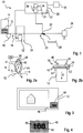
- a device 10 for quality checking and sorting documents of value, in the example banknotes, in Fig. 1 serves, inter alia, to check the manufacturing quality of documents of value 12 in the form of banknotes and for sorting depending on the result of the inspection of the manufacturing quality.
- the device 10 has an input compartment 14 for inputting documents of value 12 to be processed, a separator 16 that can access documents of value 12 in the input compartment 14, a transport device 18 that transports documents of value along a transport path 22 and a switch 20 at a junction of the transport path 22, after the switch 20 at the end of one of the two transport path branches an output compartment 26 and at the end of the other of the two transport path branches a banknote shredder 28.
- a sensor arrangement 24 is arranged, which serves to detect properties of individually supplied documents of value 12 and to form sensor signals which reproduce the properties.
- a control device 30 is connected at least to the sensor arrangement 24 and the switch 20 via signal connections and is used to evaluate sensor signals from the sensor arrangement 24, in particular to check the manufacturing quality of documents of value detected by the sensor arrangement 24, and to control at least the switch 20 as a function of the Result of the evaluation of the sensor signals.
- the sensor arrangement 24 comprises at least one sensor; In this embodiment, only one optical sensor 32 is provided for spatially resolved detection of color properties and IR properties, which detects optical radiation remitted by the value document. In other exemplary embodiments, at least one further sensor, e.g. for another property, can be provided.
- the sensor 32 While a document of value is being transported past, the sensor 32 records an overall image of the document of value in four spectral ranges accordingly the three color channels red, green and blue and in the infrared spectral range (IR channel), which is represented by corresponding sensor signals.
- IR channel infrared spectral range
- the control device 30 determines pixel data of pixels of the overall image during a sensor signal evaluation which are relevant for checking the banknotes with regard to their manufacturing quality.
- the control device 30 has an evaluation device 31 which, in the example, is integrated into the control device 30, but in other exemplary embodiments can also be part of the sensor arrangement 24, preferably the sensor 32.
- the control device 30 has a processor 34 and a memory 36 connected to the processor 34 in which at least one computer program with program code is stored Evaluates sensor signals, in particular for checking the manufacturing quality of a checked document of value, and thereby executes, inter alia, a method described below using the sensor signals or the pixel data.
- the processor controls the device or, according to the evaluation, the transport device 18.
- the evaluation device 31 therefore forms a computer within the meaning of the present invention.
- the control device 30 also has a data interface 37.
- the evaluation device 31 can use a predetermined criterion for the manufacturing quality after determining pixel data Check the value document in which at least some of the recorded properties and reference data are included.
- control device 30 controls the transport device 18, more precisely the gate 20, in such a way that the checked document of value is transported to the output compartment 26 for storage in the output compartment 26 or for destruction to the bank note destruction device 28 in accordance with its determined manufacturing quality becomes.
- the device 10 also has a user interface 35 which is connected to the control device via a signal connection and by means of which control device 30 can acquire control commands from a user which the user inputs via the user interface 35.
- a touch-sensitive display device or a touchscreen is provided as the user interface 35, which is controlled by the control device 30 to display predetermined information, and its signals that indicate the operation by a user, i.e. H. here touches of a user, represent, detected.
- the type, ie the currency and denomination, of the documents of value to be processed is first recorded by means of the user interface 35 and stored in the control device 30.
- the possible types of value documents are specified.
- documents of value 12 inserted as a stack in the input compartment 14 are separated by the separator 16 and fed individually to the transport device 18, which feeds the separated documents of value 12 to the sensor arrangement 24.
- the control device 30 detects the sensor signals, determines a production quality of the respective document of value as a function of these and, depending on the result, controls the gate 20 so that the examined documents of value are fed to the output compartment 26 or to the bank note destruction device 28 according to their determined production quality. When a value document is fed to the bank note destruction device 28, it is destroyed directly.
- the sensor 32 is designed to capture images for three colors and IR radiation.
- it is designed as a line sensor which, while a document of value is being transported past the sensor 32, comprises a sequence of line images which result in an image of the document of value in a direction transverse to the direction of the line, ie in the direction of transport.
- Figures 2a and 2b Shown schematically only in an extremely simplified manner, an illumination device 38 for illuminating a strip running transversely to the transport direction T in a transport plane E (in Figure 2b parallel to the plane of the drawing) for the document of value 12 or in a plane of the document of value 12 with convergent, white light and IR radiation during the transport of the document of value over its entire extent transversely to the transport direction T.
- the sensor 32 also includes one of the lighting device 38 emitted bundle of rays arranged detection device 40, which shadows part of the radiation of the lighting device 38.
- the illumination device has 38 via several radiation sources 39 for visible light and IR radiation arranged linearly transversely to the transport direction T, as well as two deflection elements 41 for bundling the radiation onto a strip in a transport plane for the value document 12 or on the value document 12, ie to generate an illumination strip.
- the lighting device 38 generates a projected onto an orthogonal to the transport plane E (in Fig. 2a the plane of the drawing) and the plane of convergence, which runs parallel to the direction of transport T, is a convergent beam.
- the emitted bundle of rays is initially divided by the detection device 40 into two sub-bundles, which are brought together again by the deflection devices 41 to form a convergent bundle of rays.
- the maximum opening angle ⁇ between a perpendicular to the transport plane or the detection direction D and the outermost beam of the bundle in the plane is at most 40 °, preferably at most 30 °.
- the rays are not strongly bundled; rather, the radiation is diffuse.
- the direction of illumination B results as the mean over the directions of all rays of the bundle and, because of the symmetrical course of the partial bundles, is essentially parallel to the detection direction D.
- each of the line cameras has a respective detector line with photodetection elements arranged in lines, in front of which the filter is arranged that corresponds to the color component of the remitted optical to be detected by the respective line camera Radiation corresponds.
- the sensor 32 can also include further optical elements, in particular for imaging or focusing, which are not shown here. The detector rows of photodetection elements are arranged parallel to one another.
- the sensor 32 is therefore constructed and arranged in such a way that the value document is illuminated with optical radiation from a direction B orthogonal to the plane of the value document or parallel to a normal to the transport plane in which the value document is transported and emanating from the value document 12 , remitted optical radiation is detected from a direction D orthogonal to the plane of the document of value or parallel to the direction of illumination.
- the intensity data represent pixel data which describe the properties of pixels 44 of a line image which reproduces the line-shaped area of the document of value 12 detected by the sensor 32.
- An image captured by the sensor 32 is therefore composed of pixels arranged in a rectangular matrix and is described by the pixel data.
- the resolution of the sensor 32 is at least so great that a pixel corresponds to an area of at most 0.3 mm ⁇ 0.3 mm on the value document.
- Each of the pixels is assigned color values r i , g i , b i and IR i for red, green and blue and IR remission as pixel data in addition to a number or number i, which reflects the position in the image.
- the signal processing device 44 after calibration, can generate and generate RGB color values from detection signals of the detector lines 42, 42 ', 42 "and 42"'.
- an optical security feature 46 is checked, which in this example is given by the value indication “100” in OVI print. If a viewer tilts the document of value in a suitable direction, he recognizes a change in the color of the print or the indication of value.
- the actual security feature 46 is located in a section 48 of the document of value, which is shown in Fig. 4 and Fig. 5 is indicated by hatching. In Fig. 5 the pixels are in a higher resolution than in Fig. 4 shown, but do not represent real conditions due to the schematic representation.
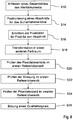
- a program is stored in the memory 36 in a section serving as part of the evaluation device 31 and thus in this example in the control device 30, which when executed by the evaluation device 31, ie here the processor 34, the following Carries out steps of a method for checking the manufacturing quality of a specified security feature of value documents.
- step S10 the evaluation device 31 uses the sensor 32 to acquire an overall image of the document of value to be checked, the type of which, i.e. the currency and denomination, is known after the input by the user described above and is stored in the control device 30.
- the sensor 32 detects overall images of the documents of value, more precisely pixel or image data representing the overall images, in the example full-area images with three color channels, namely red, green and blue (RGB channels) and an IR reflectance value; the type of pixel data has already been described above.
- the pixel data thus indicate optical properties of the value document as a function of the location on the value document.
- the pixel data are transmitted to the evaluation device 31 and recorded by it.
- preprocessing of the acquired data in the sensor 32 or the evaluation device 31 can also be carried out in this step, in which the image data is transformed, in particular filtered, for example to compensate for background noise.
- step S12 the processor 34 or the evaluation device 31 determines, depending on the type of the value document, the position of the section of the value document in which the optical security feature must be found in the case of a genuine value document.
- the position of the edges of the document of value can first be recognized, in relation to which the position of the security feature can be given.
- the section or the image of the section is in Fig. 4 marked by hatching.
- the evaluation device 31 determines one of the for the section corresponding to the security feature predetermined evaluation area 50 or ROI (region of interest) in the image, which results from the known position of the security feature on genuine value documents of the specified type relative to the outlines of the value documents and an outline of the value document determined in the image.
- the evaluation device 31 can in particular use the results of the search or detection of edges of the document of value in the overall image in order to then position the ROI in the overall image as a function of the position of the edges in the overall image, ie to select corresponding pixel data
- the processor 34 determines in step S16 the pixel data of the pixels of the overall image which correspond to locations in this section; this corresponds to a determination of an image with the security element.
- the evaluation device 31 then carries out steps for the actual checking of the security feature.
- the first reference range lies in the RB level of the RGB color space (cf. Fig. 6 (a) ), the second in a plane that is spanned by the G color values and the IR reflectance axis (cf. Fig. 6 (b) ).
- the reference areas and the parameters for the criteria have been determined before the method is carried out by using the pixel data as reference documents for a predetermined set of other freshly printed documents of value of the type with sufficient print quality for those pixels that are also used in the test.
- the mean values of the RB components or G-IR components and their variances and covariances are then determined for this pixel data to determine the respective reference area and the respective criterion according to which pixel data lie within the respective reference area, assuming a normal distribution.
- the first reference range and the first criterion are then given by determining the Mahalanobis distance in the RB plane for the pixel data of a pixel relevant to the first criterion, the R and B components, and checking whether the Mahalanobis is -Distance is smaller than a predetermined first maximum distance value.
- the parameters for calculating the Mahalanobis distance depend in a known manner on the previously determined mean values, variances and covariances. Accordingly, the maximum distance value was determined on the basis of the reference documents.
- the second reference range and the second criterion are given in that for pixel data of a pixel, here the G and IR components, the Mahalanobis distance in the G-IR plane, which is dependent on the corresponding mean values, variances and covariances, is determined and checked whether the Mahalanobis distance is smaller than a predetermined second maximum distance value that was determined for the reference value documents.
- the proportion itself is used as the hit measure for the proportion of the pixel data that lie within the respective reference area.
- a minimum hit value is defined for each of the reference areas, which must be exceeded by the hit size, in this case the portion of the pixel data in the respective reference area and which is characteristic of a security feature with sufficient manufacturing quality or a value document with such a security feature.
- Such a minimum hit value can be determined by examining the reference value documents.
- the scatter of the pixel data that lie within the first reference range is also determined and compared with a minimum scatter value that represents the minimum scatter.
- the total variance i.e. the sum of the variances of the R and B components, is used as the variance or variance measure.
- the minimum dispersion value the total variance, i.e. the sum of the variances of the R and B components, is determined as the first degree of dispersion for each of the reference value documents for the pixel data within the first reference area.
- a mean dispersion value is then determined as a minimum dispersion value which must be exceeded by a first degree of dispersion determined for a security feature to be checked so that the manufacturing quality of the security feature can be considered sufficient.
- the evaluation device 31 determines in step S18 which proportion of the pixel data for pixels corresponding to locations in the section 48 are within the first reference area by calculating the Mahalanobis distance in the RB plane for each pixel and using is compared to the maximum distance value. If the Mahalanobis distance is less than or equal to the maximum distance value, the pixel data are in the first reference area, otherwise outside. After determining the Proportion, the proportion is compared with the specified first minimum hit value.
- step S20 the evaluation device 31 or the processor 34 checks whether a first scatter of the pixel data that lie within the first reference area is greater than a predetermined minimum scatter, in this example given by a first minimum scatter value. This sum is compared with the specified first minimum dispersion value.
- step S22 the evaluation device 31 or the processor 34 then determines, in accordance with step S24, the proportion of that pixel data of the pixels used to check the security feature, ie the pixels in the section 48 that lie within the second reference area, by using for the pixel data of a respective one of the It is checked in each pixel whether the Mahalanobis distance in the G-IR plane is smaller than the corresponding second maximum distance value. If the proportion is determined, the processor 34 checks whether it exceeds the corresponding second minimum hit value.
- step S24 the evaluation device 31 or the processor 34 forms a quality signal as a function of the tests in steps S18 to S22, which, for example by its level or its shape, gives an indication of sufficient manufacturing quality, ie whether the security feature is genuine is viewed or not.
- a corresponding value is stored in the memory 36 with the quality signal.
- the quality signal is formed in such a way that it only provides an indication of sufficient manufacturing quality if the first number or the first portion exceeds the first minimum hit value, the first scatter exceeds the first minimum scatter value and the second portion exceeds the second minimum hit value.
- FIG. 6 A basis of the procedures in Figure 5 is in Fig. 6 illustrated.
- the distributions of pixel data of pixels corresponding to an OVI area in the RB color plane and the G-IR plane are shown there for a bank note. What can be seen is a typical scattering of the pixel data for the OVI element, which lies within an elliptical curve that represents a curve of equal Mahalanobis distances. If a normal copier color were used to falsify the security feature, pixel data could perhaps result which had the same mean value in the RB plane, but not the characteristic dispersion. The same applies in the example to the pixel data in the G-IR plane.
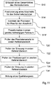
- a second embodiment in Fig. 7 differs from the first exemplary embodiment in that the evaluation device 31 carries out, as an additional step S28, a check as to whether the scatter of the pixel data within the second reference area exceeds a second minimum scatter value specified for the security feature.
- the second minimum dispersion value was previously determined analogously to the first minimum dispersion value.
- the total variance in the G-IR plane is used here as the degree of dispersion, ie the sum of the variances of the G components and the IR components of those pixel data that lie in the second reference range.
- the second minimum dispersion value can be determined analogously to the first exemplary embodiment.
- step S26 executes step S26 'instead of step S26.
- step S26 differs from step S26 solely in that the quality signal is formed in such a way that it only provides an indication of adequate manufacturing quality if, in addition to the conditions in the first exemplary embodiment, there is also the scattering of the pixel data exceeds the predefined second dispersion minimum value within the second reference range. This leads to a further increased accuracy of the test in the case of optical security features, which also have a typical scatter in the G-IR properties.
- FIG. 8 shows a corresponding variant of the first embodiment, Fig. 9 a Fig. 6 corresponding representation.
- Steps S20 to S26 are adapted to the other color space; in particular, the reference ranges and the corresponding criteria are adapted accordingly. For them, therefore, in Fig. 8 the same reference numerals are used as in the first exemplary embodiment.
- the chroma (hue) H, the saturation S and the intensity I are now used as pixel data in the HSI color space.
- Method steps S20 to S26 correspond formally to those of the corresponding steps of the first exemplary embodiment, with a and b being replaced by H and S and the reference areas, for example, correspondingly Fig. 9 can be chosen.
- step S18 ' is provided after step S16 of the method, in which the pixel data are transformed into a device-independent color space, in the example another CIE color space, so that the following steps can be carried out in a corresponding manner, in particular by specifying the Reference ranges and the criteria are adapted.
- the computer 34 transforms at least the pixel data for the section into a device-independent color space, in the example the CIE Lab color space. In the example, all pixel data of the overall image are transformed. In other exemplary embodiments, this step can also be carried out together with one of the preceding steps.
- the pixel data in the CIE-Lab color space are then used for the following process steps. These steps are identified in the figures by the use of a "T” instead of an "S”, but do not differ from the steps described above except for the use of corresponding adapted reference areas and criteria for the pixel data being in the respective reference area Embodiments.
- the first reference area lies in the ab plane of the CIE-Lab color space (see Fig. 13 (a)), the second in a plane that is spanned by the luminance axis of the CIE-Lab color values and the IR reflectance axis ( see Fig. 13 (b)).
- Figs. 13 (a) and 13 (b) for a bill, the distributions of pixel data of pixels corresponding to an OVI area are in the ab color plane and the L-IR plane shown.
- What can be seen is a typical scattering of the pixel data for the OVI element, which lies within an elliptical curve that represents a curve of equal Mahalanobis distances. If a normal copier color were used to falsify the security feature, pixel data could perhaps result which had the same mean value in the ab plane, but not the characteristic spread. The same applies in the example to the pixel data in the L-IR plane.
- the reference areas and the parameters for the criteria have been determined before the method is carried out in that, for a given set of other freshly printed documents of value of the relevant type as reference documents, the pixel data for those pixels are recorded which are also used in the check.
- the mean values of the ab components or L-IR components and their variances and covariances are then determined for this pixel data to determine the respective reference area and the respective criterion according to which pixel data lie within the respective reference area, assuming a normal distribution.
- the first reference range and the first criterion are then given by determining the Mahalanobis distance in the ab plane for the pixel data of a pixel relevant to the first criterion, the a and b components, and checking whether the Mahalanobis distance is is smaller than a predetermined first maximum distance value.
- the parameters for calculating the Mahalanobis distance depend in a known manner on the previously determined mean values, variances and covariances. Accordingly, the maximum distance value is determined on the basis of the reference documents.
- the second reference range and the second criterion are given in that for pixel data of a pixel, here the L and IR components, the Mahalanobis distance in the L-IR plane, which is dependent on the corresponding mean values, variances and covariances, is determined and checked becomes, whether the Mahalanobis distance is less than a predetermined second maximum distance value that was determined for the reference value documents.
- the proportion itself is used as the hit measure for the proportion of the pixel data that lie within the respective reference area.
- a minimum hit value is defined for each of the reference areas, which must be exceeded by the hit size, in this case the portion of the pixel data in the respective reference area and which is characteristic of a security feature with sufficient manufacturing quality or a value document with such a security feature.
- Such a minimum hit value can be determined by examining the reference value documents.
- the scatter of the pixel data that lie within the first reference range is additionally determined and compared with a minimum scatter value.
- the total variance ie the sum of the variances of the a and b components, is used as the scatter or degree of scatter.
- the minimum value for dispersion the total variance, ie the sum of the variances of the a and b components, is determined as the first degree of dispersion for each of the reference value documents for the pixel data within the first reference area. From the distribution of the total variances determined, a mean dispersion value is then determined as a minimum dispersion value which must be exceeded by a first degree of dispersion determined for a security feature to be checked so that the manufacturing quality of the security feature can be considered sufficient.
- the evaluation device 31 determines in step T20 which portion of the pixel data for pixels that correspond to locations in the section 48 lie within the first reference area by for each pixel the Mahalanobis distance in the ab plane is calculated and compared with the maximum distance value. If the Mahalanobis distance is less than or equal to the maximum distance value, the pixel data are in the first reference area, otherwise outside. After determining the proportion, the proportion is compared with the specified first minimum hit value.
- step T22 the evaluation device 31 or the processor 34 checks whether a first scatter of the pixel data that lie within the first reference area is greater than a predefined minimum scatter value. This sum is compared with the specified first minimum scatter value.
- step T24 the evaluation device 31 or the processor 34 then determines, in accordance with step S24, the proportion of that pixel data of the pixels used to check the security feature, ie the pixels in the section 48 that lie within the second reference area, by using for the pixel data of a respective one of the It is checked in each pixel whether the Mahalanobis distance in the L-IR plane is smaller than the corresponding second maximum distance value. If the proportion is determined, the processor 34 checks whether it exceeds the corresponding second minimum hit value.
- step T26 the evaluation device 31 or the processor 34 forms a quality signal as a function of the tests in steps T24 to T28, as in the first exemplary embodiment.
- FIG. 11 differs from the first embodiment in that the evaluation device 31 carries out, as an additional step T28, a check as to whether the scatter of the pixel data within the second reference area exceeds a second minimum scatter value specified for the security feature.
- the second minimum dispersion value was previously established in a manner analogous to the first minimum dispersion value.
- the total variance in the L-IR plane is used here as the degree of dispersion, ie the sum of the variances of the L components and the IR components of those pixel data that lie in the second reference range.
- the second minimum dispersion value can be determined analogously to the first exemplary embodiment.
- step T26 executes step T26 'instead of step T26.
- this differs from step T26 solely in that the quality signal is formed in such a way that it only provides an indication of adequate manufacturing quality if, in addition to the conditions in the first exemplary embodiment, the scatter of the pixel data within the second reference area exceeds the predetermined second minimum dispersion value. This leads to a further increased accuracy of the test in the case of optical security features, which also have a typical scatter in the L-IR properties.
- step S16 can differ from the exemplary embodiments described above in that in step S16 the section is only a rectangle in a center of the security feature, but not the smallest rectangle surrounding the security feature.
- pixel data are used which only reproduce colors.
- the second criterion and the second reference range can then be given in that the L component must lie in a predetermined value range so that the pixel data lie within the second reference range.
- Still further exemplary embodiments differ from the exemplary embodiments described in that an embossed structure is used as an optical security feature with a print formed on certain flanks of the embossed structure, which has an optically variable effect.
- embossed structures are in the applications WO 97/17211 A1 , WO 02/20280 A1 , WO 2004/022355 A2 , WO 2006/018232 A1 described by the applicant.
- Still further exemplary embodiments differ from the exemplary embodiments described only in that a sensor such as the one used is used as the sensor WO 96/36021 A1 is described, the content of which is incorporated into the description by reference.
- exemplary embodiments differ from the exemplary embodiments described, in which the HSI or the CIE Lab color space is used, in that only the first reference range is used, so that steps S28 and T28 can be omitted and steps S26 and T26, respectively are changed accordingly, so that the quality signal is only formed when the number of pixel data in the first reference area exceeds the minimum proportion and the spread of the pixel data within the first reference area exceeds the first minimum spread.
- Still further exemplary embodiments differ from those described above in that no IR component is present.
- the second reference area is then one-dimensional and the second criterion is adapted accordingly.
- exemplary embodiments differ from the exemplary embodiments described up to now in that the entry of the value document type by a user is omitted, and instead of after step S10 a step S11 is carried out in which the type is automatically determined. More precisely, the evaluation device 31 or: the processor 34 determines in this step S12 the type, ie the currency and the denomination, of a document of value to be checked as a function of the pixel data detected by the sensor 32. Different types are given. If possible, one of the predefined types can then be assigned to the value document. In the example, value documents are to be checked, the format of which depends on the type. The evaluation device 31 can therefore first carry out a search or recognition of edges of the bank note in the image. From the recognized margins, it can determine the format of the value document, the denomination or denomination and thus the type from the set of predefined possible value document types.
- the evaluation device 31 can therefore first carry out a search or recognition of edges of the bank note in the image. From the recognized margins, it can determine the format of the value document
- Still further exemplary embodiments differ from the preceding exemplary embodiments in that two scatter in two mutually orthogonal directions in the corresponding color space are used as the degree of scatter.
- the directions are given by the eigenvectors of the variance matrix of the pixel data or pixel data components for the security feature of the reference documents in the respective reference areas.
- the variance of the projection of the pixel data onto the one eigenvector and the variance of the projection of the pixel data onto the other eigenvector are then used as the scatter.
- a threshold value is then specified for each of the directions, which threshold value can be determined in each case by evaluating pixel data for the reference documents in a manner analogous to the first exemplary embodiment.
- the threshold values represent the minimum scatter. The scatter exceeds the minimum scatter if the variance for one of the directions is greater than the threshold value assigned to the respective direction.
- the evaluation device can be integrated into the sensor.
- exemplary embodiments can differ from the preceding exemplary embodiments in that, instead of a line camera, a camera with an array of detection elements arranged in a matrix is provided.
- sensor sections spaced apart from one another in the transport direction are provided in order to detect at least different components of the pixel data.
- two parts could be provided, one of which includes lighting and a camera for detecting optical properties in the visible spectral range and the other lighting and camera for detecting optical properties in the non-visible spectral range, in particular the IR range.
- the captured images in the example two, must first be brought into congruence or positioned one on top of the other so that the necessary number of components is available for a location.
Description
Die vorliegende Erfindung betrifft ein Verfahren zum Prüfen der Herstellungsqualität eines optischen Sicherheitsmerkmals in oder auf einem Abschnitt eines Wertdokuments auf der Basis von Pixeldaten eines Bildes des Abschnitts, ein Verfahren zum Prüfen eines optischen Sicherheitsmerkmals eines Wertdokuments und eine Vorrichtung zum Prüfen eines optischen Sicherheitsmerkmals eines Wertdokuments.The present invention relates to a method for checking the manufacturing quality of an optical security feature in or on a section of a value document on the basis of pixel data of an image of the section, a method for checking an optical security feature of a value document and a device for checking an optical security feature of a value document.
Unter Wertdokumenten werden dabei karten- und vorzugsweise blattförmige Gegenstände verstanden, die beispielsweise einen monetären Wert oder eine Berechtigung repräsentieren und daher nicht beliebig durch Unbefugte herstellbar sein sollen. Sie weisen daher nicht einfach herzustellende, insbesondere zu kopierende Sicherheitsmerkmale auf, deren Vorhandsein ein Indiz für die Echtheit, d.h. die Herstellung durch eine dazu befugten Stelle, ist. Wichtige Beispiele für solche Wertdokumente sind Ausweisdokumente, Chipkarten, Coupons, Gutscheine, Schecks und insbesondere Banknoten.In this context, documents of value are understood to be card-shaped and preferably sheet-shaped objects which, for example, represent a monetary value or an authorization and should therefore not be able to be produced by unauthorized persons at will. They therefore have security features that are not easy to produce, in particular to be copied, whose presence is an indication of authenticity, i.e. production by an authorized body. Important examples of such documents of value are identification documents, chip cards, coupons, vouchers, checks and, in particular, bank notes.
Von besonderem Interesse sind optische Sicherheitsmerkmale, unter denen im Rahmen der vorliegenden Erfindung Sicherheitsmerkmale eines Wertdokuments verstanden werden, die charakteristische optische Eigenschaften bei der Wechselwirkung mit optischer Strahlung, d.h. elektromagnetischer Strahlung im infraroten, ultravioletten oder sichtbaren Spektralbereich, zeigen. Die optischen Eigenschaften können insbesondere Remissions- und/oder Transmissions- und/oder Lumineszenzeigenschaften sein.Of particular interest are optical security features, which in the context of the present invention are understood to be security features of a value document which show characteristic optical properties when interacting with optical radiation, i.e. electromagnetic radiation in the infrared, ultraviolet or visible spectral range. The optical properties can in particular be remission and / or transmission and / or luminescence properties.
Bestimmte Typen von Sicherheitsmerkmalen, im folgenden auch als Humanmerkmal bezeichnet, sind dazu vorgesehen, ohne technische Hilfsmittel auf Echtheit geprüft werden zu können. Beispiele für solche Sicherheitsmerkmale sind insbesondere sogenannte OVD-Merkmale, unter denen im Folgenden Sicherheitsmerkmale verstanden werden, die betrachtungswinkelabhängige visuelle Effekte zeigen bzw. deren optische Eigenschaften, beispielsweise die Farbe, vom Betrachtungswinkel abhängen. Solche Sicherheitsmerkmale können einem Betrachter unter unterschiedlichen Betrachtungswinkeln einen unterschiedlichen Bildeindruck vermitteln und beispielsweise je nach Betrachtungswinkel einen anderen Farb- oder Helligkeitseindruck und/oder ein anderes graphisches Motiv zeigen. Solche modernen Humanmerkmale sind allerdings nicht einfach herzustellen. Daher kann es passieren, daß Wertdokumente mit solchen Humanmerkmalen hergestellte werden, die sich letztlich nicht hinreichend für eine Prüfung ohne technische Hilfsmittel eignen. Ähnliche Probleme können auch bei anderen, schwer herzustellenden optischen Sicherheitsmerkmalen auftreten.Certain types of security features, also referred to below as human features, are intended to be able to be checked for authenticity without technical aids. Examples of such security features are in particular so-called OVD features, among which im The following security features are understood, which show viewing angle-dependent visual effects or whose optical properties, for example the color, depend on the viewing angle. Such security features can convey a different image impression to a viewer from different viewing angles and, for example, show a different color or brightness impression and / or a different graphic motif depending on the viewing angle. Such modern human traits, however, are not easy to produce. It can therefore happen that value documents are produced with such human characteristics that are ultimately not sufficiently suitable for checking without technical aids. Similar problems can also arise with other optical security features that are difficult to manufacture.
In
In
In
In
Der vorliegenden Erfindung liegt daher die Aufgabe zugrunde, Verfahren zur Prüfung der Herstellungsqualität von optischen OVD-Sicherheitsmerkmalen von Wertdokumenten anzugeben, die eine schnelle und genaue Prüfung der Herstellungsqualität erlauben, sowie Mittel zur Durchführung des Verfahrens zu schaffen.The present invention is therefore based on the object of specifying methods for checking the manufacturing quality of optical OVD security features of value documents, which allow a quick and precise checking of the manufacturing quality, as well as creating means for carrying out the method.
Die Aufgabe wird erstens gelöst durch ein Verfahren zum Prüfen, vorzugsweise computergestützten, Prüfen der Herstellungsqualität eines vorgegebenen optischen Sicherheitsmerkmals, vorzugsweise OVD-Sicherheitsmerkmals, in oder auf einem vorgegebenen Abschnitt eines Wertdokuments auf der Basis von Pixeldaten von Pixeln eines ortsaufgelösten Bildes des vorgegebenen Abschnitts, die jeweils Orten in bzw. auf dem Abschnitt zugeordnet sind und optische Eigenschaften des Wertdokuments an den Orten wiedergeben. Bei dem Verfahren wird geprüft, ob eine erste Anzahl derjenigen Pixel oder ein erster Anteil derjenige Pixel an den Pixeln des Bildes, deren Pixeldaten gemäß einem ersten für das Sicherheitsmerkmal vorgegebenen Kriterium innerhalb eines für das Sicherheitsmerkmal vorgegebenen ersten Referenzbereichs für die Pixeldaten liegen, einen für das Sicherheitsmerkmal vorgegebenen ersten Treffermindestwert übersteigt, und ob eine Streuung der Pixeldaten derjenigen Pixel die nach dem ersten Kriterium innerhalb des ersten Referenzbereichs liegen, eine für das Sicherheitsmerkmal vorgegebene ersten Mindeststreuung übersteigt, und in Abhängigkeit vom Ergebnis der Prüfung ein Qualitätssignal gebildet wird, das nur dann einen Hinweis auf eine hinreichende Herstellungsqualität darstellt, wenn nach dem ersten Kriterium die erste Anzahl bzw. der erste Anteil den ersten Treffermindestwert und die Streuung die erste Mindeststreuung überschreiten, und/oder das einen Hinweis auf eine Herstellungsfehler darstellt, wenn die erste Anzahl bzw. der erste Anteil den ersten Treffermindestwert und die Streuung die erste Mindeststreuung nicht überschreitet.The object is achieved firstly by a method for checking, preferably computer-aided, checking the manufacturing quality of a specified optical security feature, preferably OVD security feature, in or on a specified section of a document of value on the basis of pixel data from pixels of a spatially resolved image of the specified section, which are respectively assigned to locations in or on the section and reproduce optical properties of the document of value at the locations. The method checks whether a first number of those pixels or a first proportion of those pixels in the pixels of the image, their pixel data according to a first criterion specified for the security feature within a first reference range specified for the security feature for the pixel data, exceeds a first minimum hit value specified for the security feature, and whether a scatter of the pixel data of those pixels that are within the first reference range according to the first criterion exceeds a first minimum scatter specified for the security feature, and depending on the result of the check Quality signal is formed which only represents an indication of sufficient manufacturing quality if, according to the first criterion, the first number or the first proportion exceed the first minimum hit value and the spread exceeds the first minimum spread, and / or which represents an indication of a manufacturing defect, if the first number or the first proportion does not exceed the first minimum hit value and the spread does not exceed the first minimum spread.
Die Aufgabe wird zweitens gelöst durch ein Verfahren zum Prüfen der Herstellungsqualität eines vorgegebenen optischen Sicherheitsmerkmals in oder auf einem vorgegebenen Abschnitt eines Wertdokuments, bei dem zur Erfassung eines Bildes des vorgegebenen Abschnitts das Wertdokument mit optischer Strahlung einer optischen Strahlungsquelle beleuchtet und von dem Wertdokument ausgehende Strahlung mit einer Erfassungseinrichtung erfaßt wird, in Abhängigkeit von der erfaßten Strahlung Pixeldaten von Pixeln des Bildes, die jeweils Orten in bzw. auf dem Abschnitt zugeordnet sind und optische Eigenschaften des Wertdokuments an den Orten wiedergeben, gebildet werden und bei dem ein Verfahren nach einem der vorhergehenden Ansprüche durchgeführt wird, bei dem als Pixeldaten die gebildeten Pixeldaten verwendet werden.Secondly, the object is achieved by a method for checking the manufacturing quality of a given optical security feature in or on a given section of a value document, in which, in order to capture an image of the given section, the value document is illuminated with optical radiation from an optical radiation source and radiation emanating from the value document is also illuminated a detection device is detected, depending on the detected radiation, pixel data of pixels of the image, which are respectively assigned to locations in or on the section and reproduce optical properties of the document of value at the locations, are formed and in which a method according to one of the preceding claims is carried out in which the formed pixel data are used as the pixel data.
Unter der Herstellungsqualität wird im Fall von gedruckten Sicherheitsmerkmalen vorzugsweise die Druckqualität verstanden. Der Hinweis auf die hinreichende Herstellungsqualität ist dann ein Hinweis auf eine hinreichende Druckqualität, der Hinweis auf den Herstellungsfehler ein Hinweis auf einen Druckfehler.In the case of printed security features, the production quality is preferably understood to mean the print quality. The indication of the adequate manufacturing quality is then an indication of an adequate one Print quality, the indication of the manufacturing defect, an indication of a printing error.
Bei den Verfahren werden Pixeldaten von Pixeln eines Bildes des vorgegebenen Abschnitts eines Wertdokuments verwendet, in oder auf dem das Sicherheitsmerkmal bei einem echten Wertdokument ausgebildet ist. Die Lage und Form des Abschnitts kann sich daher nach der Lage des Sicherheitsmerkmals auf einem echten Wertdokument bzw. der Form des Sicherheitsmerkmals richten. Der Abschnitt kann dabei insbesondere für einen bestimmten Typ von zu prüfendem Wertdokument, bei Banknoten insbesondere einer Währung und Stückelung bzw. Denomination der Banknoten, und das vorgegebene zu prüfende Sicherheitsmerkmal vorgegeben sein. Der Abschnitt kann beispielsweise durch die Fläche des Sicherheitsmerkmals oder nur einen vorgegebenen Teil der von dem Sicherheitsmerkmal eingenommenen Fläche gegeben sein. Das Bild kann insbesondere ein Teilbild eines Gesamtbildes des gesamten Wertdokuments sein.In the case of the method, pixel data of pixels of an image of the predetermined section of a value document are used, in or on which the security feature is formed in the case of a genuine value document. The position and shape of the section can therefore be based on the position of the security feature on a real value document or the shape of the security feature. The section can in particular be specified for a specific type of document of value to be checked, in the case of bank notes in particular a currency and denomination or denomination of the bank notes, and the specified security feature to be checked. The section can be given, for example, by the area of the security feature or only a predetermined part of the area occupied by the security feature. The image can in particular be a partial image of an overall image of the entire document of value.
Die Pixeldaten eines jeweiligen Pixels geben optische Eigenschaften an einem dem jeweiligen Pixel zugeordneten Ort in dem Abschnitt des Wertdokuments wieder. Die Pixeldaten für ein jeweiliges Pixel können im allgemeinen mehrere Komponenten aufweisen, die verschiedene optische Eigenschaften darstellen.The pixel data of a respective pixel reproduce optical properties at a location assigned to the respective pixel in the section of the value document. The pixel data for a respective pixel can generally have several components which represent different optical properties.
Zur Prüfung des Sicherheitsmerkmals werden zwei Teilprüfungen herangezogen: Zum einen wird geprüft, ob die Pixeldaten innerhalb des ersten Referenzbereichs liegen, der für das Sicherheitsmerkmal vorgegeben ist. Hierzu wird das vorgegebene erste Kriterium für die Pixeldaten verwendet, mittels dessen die Lage der Pixeldaten in Bezug auf den ersten Referenzbereich ermittelbar ist. Damit wird geprüft, ob die optischen Eigenschaften des untersuchten Abschnitts des Wertdokuments innerhalb vorgegebener Grenzen liegen, die für das Sicherheitsmerkmal vorgegeben sind. Zum anderen wird geprüft, ob die Streuung der Pixeldaten innerhalb des ersten Referenzbereichs die für das Sicherheitsmerkmal vorgegebene erste Mindeststreuungsmindestwert übersteigt. Das bedeutet, daß geprüft wird, ob die Pixeldaten in dem ersten Referenzbereich nur in einem Teil des ersten Referenzbereichs konzentriert oder eher in diesem breiter gestreut verteilt sind.Two sub-tests are used to check the security feature: On the one hand, it is checked whether the pixel data lie within the first reference area that is specified for the security feature. For this purpose, the predefined first criterion for the pixel data is used, by means of which the position of the pixel data in relation to the first reference area can be determined. This is used to check whether the optical properties of the examined Section of the value document lie within predetermined limits that are predetermined for the security feature. On the other hand, it is checked whether the scatter of the pixel data within the first reference area exceeds the first minimum scatter minimum value specified for the security feature. This means that a check is made as to whether the pixel data in the first reference area are concentrated only in a part of the first reference area or rather are distributed more widely in this area.
In Abhängigkeit vom Ergebnis der Prüfung wird dann das Qualitätssignal gebildet. Dieses gibt, beispielsweise durch seine Form oder seinen Pegel, bei einem Datensignal insbesondere seinen Inhalt, wieder bzw. stellt dar, ob die Prüfung einen Hinweis auf eine hinreichende Herstellungsqualität ergeben hat, und/oder ob die Prüfung einen Hinweis auf einen Herstellungsfehler ergeben hat. Vorzugsweise wird das Qualitätssignal bei jeder Prüfung, d.h. unabhängig vom Ergebnis der Prüfung gebildet; dann gibt es entweder den Hinweis auf eine hinreichende Herstellungsqualität oder den Hinweis auf einen Herstellungsfehler wieder. Insbesondere stellt es den Hinweis auf eine hinreichende Herstellungsqualität nur dann dar, wenn die erste Anzahl bzw. der erste Anteil den ersten Treffermindestwert und die Streuung die erste Mindeststreuung überschreiten. Das Qualitätssignal kann zur Speicherung eines Hinweises auf eine hinreichende Herstellungsqualität oder eines Hinweises auf einen Herstellungsfehler in einer Speichereinrichtung verwendet werden. Der Qualitätshinweis kann bei einer optionalen weiteren Prüfung der Herstellungsqualität des Sicherheitsmerkmals oder der Prüfung der Herstellungsqualität des gesamten Wertdokuments allein als Kriterium für einen Herstellungsfehler verwendet werden, so daß das Sicherheitsmerkmal bzw. Wertdokument bei Vorliegen des Hinweises auf einen Herstellungsfehler oder bei Fehlen eines Hinweises auf eine hinreichende Herstellungsqualität als fehlerhaft klassifiziert wird. Es ist, insbesondere bei der Prüfung von Wertdokumenten mit insgesamt wenigstens zwei verschiedenen Sicherheitsmerkmalen, aber auch möglich, daß das Qualitätssignal mit anderen Qualitätssignalen, die die Herstellungsqualität anderer Merkmale des Wertdokuments darstellen, in einem Gesamtkriterium zusammengeführt wird; dann wird der Qualitätshinweis gegebenenfalls nur als notwendige Bedingung für eine hinreichende Herstellungsqualität verwendet.The quality signal is then generated as a function of the result of the test. In the case of a data signal, for example by its shape or its level, this reproduces its content, in particular, or shows whether the test has indicated an indication of adequate manufacturing quality and / or whether the check has indicated an indication of a manufacturing defect. The quality signal is preferably formed for each test, ie independently of the result of the test; then there is either an indication of adequate manufacturing quality or an indication of a manufacturing defect. In particular, it is an indication of adequate manufacturing quality only if the first number or the first portion exceeds the first minimum hit value and the scatter exceeds the first minimum scatter. The quality signal can be used to store an indication of sufficient manufacturing quality or an indication of a manufacturing defect in a storage device. The quality notice can be used in an optional further check of the manufacturing quality of the security feature or the check of the manufacturing quality of the entire document of value solely as a criterion for a manufacturing defect, so that the security feature or document of value when there is a reference to a manufacturing defect or if there is no reference to a Sufficient manufacturing quality is classified as defective. It is especially when testing Documents of value with a total of at least two different security features, but it is also possible for the quality signal to be combined in an overall criterion with other quality signals which represent the manufacturing quality of other features of the document of value; then the quality notice is only used as a necessary condition for an adequate manufacturing quality.
Obwohl die Anzahl der Pixel des Bildes nur größer als 5 zu sein braucht, ist sie vorzugsweise größer als 48, so daß der Anteil bzw. die Anzahl der Pixel in dem ersten Referenzbereich und deren Streuung darin auch aussagekräftig sind.Although the number of pixels in the image need only be greater than 5, it is preferably greater than 48, so that the proportion or the number of pixels in the first reference area and their scatter therein are also meaningful.
Damit wird die Prüfung von optischen Sicherheitsmerkmalen ermöglicht, die sich durch eine Streuung von optischen Eigenschaften innerhalb eines vorgegebenen Bereichs auszeichnen, die charakteristisch für das Sicherheitsmerkmal und nicht einfach, beispielsweise durch Kopieren mit einem Farbkopierer oder Drucken mit einem Laserdrucker, zu fälschen ist. Insbesondere kann das Verfahren zur Prüfung von OVD-Sicherheitsmerkmalen verwendet werden.This enables the testing of optical security features that are characterized by a scattering of optical properties within a predetermined range, which are characteristic of the security feature and are not easy to forge, for example by copying with a color copier or printing with a laser printer. In particular, the method can be used to check OVD security features.
Gemäß einer bevorzugten Ausführungsform kann das Sicherheitsmerkmal ein sogenanntes OVD-Sicherheitsmerkmal sein, das durch Druck mit einer Druckfarbe mit Pigmenten erhalten werden kann, deren Remissionseigenschaften von der Einfallsrichtung optischer Strahlung auf ein jeweiliges Pigmentteilchen geprägt wird. Solche Druckfarben werden auch als "optically variable inks", im folgenden auch als "optisch variable Druckfarben", bezeichnet. Unter einem Sicherheitsmerkmal mit optisch variablen Druckfarben wird insbesondere auch ein Sicherheitsmerkmal verstanden, das mit einer Druckfarbe gedruckt ist, die Pigmente enthält, deren Farbe von der Richtung der Beleuchtung und der Richtung der Detektion bzw. Beobachtung abhängt.According to a preferred embodiment, the security feature can be a so-called OVD security feature, which can be obtained by printing with a printing ink with pigments whose reflectance properties are influenced by the direction of incidence of optical radiation on a particular pigment particle. Such printing inks are also referred to as “optically variable inks”, hereinafter also referred to as “optically variable printing inks”. A security feature with optically variable printing inks is also understood to mean, in particular, a security feature that is printed with a printing ink that contains pigments, the color of which depends on the direction the lighting and the direction of detection or observation depends.
Gemäß einer anderen Ausführungsform kann das Sicherheitsmerkmal eine in dem Wertdokument ausgebildete Oberflächenstruktur, insbesondere eine Prägestruktur, mit einem auf bestimmten Flanken der Oberflächenstruktur bzw. Prägestruktur ausgebildeten Druck sein, die einen optisch variablen Effekt aufweist. Unter einem optisch variablen Effekt wird im Rahmen der vorliegenden Erfindung ein Effekt verstanden, bei dem vorgegebene optische Eigenschaften einer Struktur oder eines Sicherheitsmerkmals von der Richtung, aus der diese bzw. dieses betrachtet wird, und/oder der Richtung aus der die Struktur bzw. das Sicherheitsmerkmal zur Betrachtung beleuchtet wird, abhängen; insbesondere kann es sich bei den optischen Eigenschaften um Farben handeln. Solche Oberflächenstrukturen in Form von Prägestrukturen sind in den Anmeldungen
Bei dem ersten Verfahren erfolgt die Prüfung unter Verwendung einer geeigneten Vorrichtung, vorzugsweise computergestützt; unter "computergestütztem Prüfen" wird im Rahmen der vorliegenden Erfindung jegliche Prüfung mit einem Computer verstanden. Unter einem Computer wird im Rahmen der Erfindung allgemein eine Datenverarbeitungseinrichtung verstanden, die die Pixeldaten verarbeitet. Insbesondere kann die Datenverarbeitungseinrichtung dazu ein FPGA, einen Mikrocontroller oder Mikroprozessor, insbesondere auch einen DSP, oder eine Kombination dieser Komponenten umfassen oder nur eine dieser Komponenten aufweisen. Weiter kann sie einen Speicher umfassen, in dem ein Programm gespeichert ist, bei dessen Ausführung auf dem Computer das erfindungsgemäße erste Verfahren ausgeführt wird.In the first method, the test is carried out using a suitable device, preferably computer-aided; In the context of the present invention, “computer-aided testing” is understood to mean any testing with a computer. In the context of the invention, a computer is generally understood to mean a data processing device which processes the pixel data. In particular, for this purpose the data processing device can be an FPGA, a microcontroller or microprocessor, in particular also a DSP, or a combination of these components include or have only one of these components. It can furthermore comprise a memory in which a program is stored, the first method according to the invention being executed when it is executed on the computer.
Gegenstand der Erfindung ist daher auch ein Computerprogramm mit Programmcode-Mitteln, um das erste erfindungsgemäße Verfahren durchzuführen, wenn das Programm auf einem Computer ausgeführt wird.The invention therefore also relates to a computer program with program code means in order to carry out the first method according to the invention when the program is executed on a computer.
Gegenstand der Erfindung ist auch eine Computerprogrammprodukt mit Programmcode-Mitteln, die auf einem computerlesbaren Datenträger gespeichert sind, um das erfindungsgemäße erste Verfahren durchzuführen, wenn das Computerprogrammprodukt auf einem Computer ausgeführt wird.The invention also relates to a computer program product with program code means which are stored on a computer-readable data carrier in order to carry out the first method according to the invention when the computer program product is executed on a computer.
Gegenstand der Erfindung ist auch eine Prüfeinrichtung zur Prüfung eines vorgegebenen Sicherheitsmerkmals eines Wertdokuments mittels des erfindungsgemäßen Verfahrens mit einem optischen Sensor zur Erfassung eines Bildes mit Pixeln, deren Pixeldaten jeweils Orten in bzw. auf dem Abschnitt zugeordnet sind und optische Eigenschaften des Wertdokuments an den Orten wiedergeben, einem Speicher zur Speicherung eines erfindungsgemäßen Computerprogramms und einem Computer zur Ausführung des Computerprogramms mit von dem Sensor erfaßten Bildern.The invention also relates to a test device for testing a predetermined security feature of a document of value by means of the method according to the invention with an optical sensor for capturing an image with pixels, the pixel data of which are assigned to locations in or on the section and reproduce optical properties of the document of value at the locations , a memory for storing a computer program according to the invention and a computer for executing the computer program with images captured by the sensor.
Prinzipiell kann es genügen, nur die genannten Teilprüfungen vorzunehmen. Vorzugsweise wird jedoch zusätzlich geprüft, ob eine zweite Anzahl derjenigen Pixel oder ein zweiter Anteil derjenigen Pixel an den Pixeln des Bildes, deren Pixeldaten gemäß einem zweiten für das Sicherheitsmerkmal vorgegebenen Kriterium innerhalb eines für das Sicherheitsmerkmal vorgegebenen zweiten Referenzbereichs liegen, einen für das Sicherheitsmerkmal vorgegebenen zweiten Treffermindestwert übersteigt. Das Qualitätssignal kann dann so gebildet werden, daß es den Hinweis auf eine hinreichende Herstellungsqualität nur dann darstellt, wenn zusätzlich die zweite Anzahl bzw. der zweite Anteil den zweiten Treffermindestwert übersteigt, und/oder daß es einen Hinweis auf eine Herstellungsfehler darstellt, wenn die zweite Anzahl bzw. der zweite Anteil den zweiten Treffermindestwert nicht überschreitet. Diese Variante bietet den Vorteil, daß eine differenziertere Prüfung des Sicherheitsmerkmals möglich wird.In principle, it may be sufficient to only carry out the specified partial examinations. Preferably, however, it is additionally checked whether a second number of those pixels or a second proportion of those pixels in the pixels of the image, their pixel data according to a second criterion predetermined for the security feature, within a predetermined one for the security feature second reference range, exceeds a predetermined second minimum hit value for the security feature. The quality signal can then be formed in such a way that it only represents an indication of sufficient manufacturing quality if the second number or the second proportion also exceeds the second minimum hit value, and / or that it represents an indication of a manufacturing error if the second Number or the second proportion does not exceed the second minimum hit value. This variant offers the advantage that a more differentiated check of the security feature is possible.
Bei einer bevorzugten Weiterbildung kann geprüft werden, ob eine Streuung der Pixeldaten derjenigen Pixel, die gemäß dem zweiten Kriterium innerhalb des zweiten Referenzbereichs liegen, eine für das Sicherheitsmerkmal vorgegebene zweite Mindeststreuung übersteigt. Das Qualitätssignal kann dann so gebildet wird, daß es den Hinweis auf eine hinreichende Herstellungsqualität nur dann darstellt, wenn zusätzlich die Streuung der Pixeldaten in dem zweiten Referenzbereich die zweite Mindeststreuung überschreitet, und/oder daß es einen Hinweis auf einen Herstellungsfehler darstellt, wenn die Streuung der Pixeldaten in dem zweiten Referenzbereich die zweite Mindeststreuung nicht überschreitet. Diese Ausführungsform erlaubt insbesondere die Prüfung von Sicherheitsmerkmalen die wenigstens zwei verschiedene charakteristisch streuende optische Eigenschaften aufweisen.In a preferred development, it can be checked whether a scatter of the pixel data of those pixels which, according to the second criterion, lie within the second reference area exceeds a second minimum scatter specified for the security feature. The quality signal can then be formed in such a way that it only represents an indication of adequate manufacturing quality if the scatter of the pixel data in the second reference area also exceeds the second minimum scatter, and / or that it represents an indication of a manufacturing error if the scatter of the pixel data in the second reference area does not exceed the second minimum scatter. This embodiment allows, in particular, the testing of security features which have at least two different characteristically scattering optical properties.
Die Pixeldaten können prinzipiell beliebige optische Eigenschaften wiedergeben und hierzu eine entsprechende Anzahl von Komponenten für jeden Ort aufweisen, die die optischen Eigenschaften darstellen. Obwohl die Anzahl der Komponenten prinzipiell nicht beschränkt ist, liegt sie vorzugsweise unter sechs, beträgt aber wenigstens zwei.In principle, the pixel data can reproduce any optical properties and, for this purpose, have a corresponding number of components for each location that represent the optical properties. Although the number of components is not limited in principle, it is preferably less than six, but is at least two.
Bei einer ersten Ausführungsform weisen die Pixeldaten für jeweils ein Pixel bzw. einen Ort Komponenten auf, die Remissions- oder Transmissionseigenschaften in wenigstens zwei, vorzugsweise drei verschiedenen Wellenlängenbereichen, vorzugsweise innerhalb des sichtbaren Spektralbereichs, oder wenigstens zwei, vorzugsweise drei Farben wiedergeben. Hierzu kann das Beleuchten mit optischer Strahlung und das Erfassen von Strahlung so erfolgen, daß die Pixeldaten für jeweils ein Pixel bzw. einen Ort die genannten Komponenten aufweisen. Bei einer Darstellung von Farben werden vorzugsweise wenigstens zwei, besser drei Farbkomponenten verwendet, obwohl auch Farbdarstellungen in höherdimensionalen Farbräumen möglich sind. Insbesondere brauchen die Pixeldaten bei einer Variante außer Farbkomponenten in einem dreidimensionalen Farbraum keine weiteren Komponenten aufzuweisen. Dies erlaubt eine schnelle Ausführung der Prüfung.In a first embodiment, the pixel data for one pixel or one location each have components that reproduce reflectance or transmission properties in at least two, preferably three different wavelength ranges, preferably within the visible spectral range, or at least two, preferably three colors. For this purpose, the illumination with optical radiation and the detection of radiation can take place in such a way that the pixel data for one pixel or one location each have the components mentioned. In the case of a representation of colors, preferably at least two, better still three, color components are used, although color representations in higher-dimensional color spaces are also possible. In particular, in one variant, the pixel data need not have any other components apart from color components in a three-dimensional color space. This allows the test to be carried out quickly.
Bei einer zweiten Ausführungsform weisen die Pixeldaten für jeweils ein Pixel bzw. einen Ort Komponenten auf, die Remissions- und/oder Transmissionseigenschaften in wenigstens zwei, vorzugsweise wenigstens drei verschiedenen Wellenlängenbereichen innerhalb des sichtbaren Spektralbereichs oder wenigstens zwei, vorzugsweise wenigstens drei Farben und Remissions- und/oder Transmissionseigenschaften in einem weiteren Wellenlängenbereich wenigstens teilweise außerhalb des sichtbaren Spektralbereichs, vorzugsweise im infraroten Spektralbereich, darstellen. Hierzu kann das Beleuchten mit optischer Strahlung und das Erfassen von Strahlung so erfolgen, daß die Pixeldaten für jeweils ein Pixel bzw. einen Ort die genannten Komponenten aufweisen. Die Verwendung von solchen Pixeldaten erlaubt insbesondere eine Prüfung von Sicherheitsmerkmalen, die sich auch durch charakteristische Eigenschaften im nicht sichtbaren optischen Spektralbereich auszeichnen. Bei einer Darstellung von Farben werden auch hier vorzugsweise die wenigstens zwei, bzw. besser drei Farbkomponenten verwendet. Insbesondere brauchen die Pixeldaten bei einer Variante außer Farbkomponenten in einem zwei- oder dreidimensionalen Farbraum und einer Komponente für die optischen Eigenschaften in dem nicht sichtbaren Spektralbereich keine weiteren Komponenten aufzuweisen. Dies erlaubt eine schnelle Ausführung der Prüfung.In a second embodiment, the pixel data for one pixel or one location each have components that reflect reflectance and / or transmission properties in at least two, preferably at least three different wavelength ranges within the visible spectral range or at least two, preferably at least three colors and reflectance and / or represent transmission properties in a further wavelength range at least partially outside the visible spectral range, preferably in the infrared spectral range. For this purpose, the illumination with optical radiation and the detection of radiation can take place in such a way that the pixel data for one pixel or one location each have the components mentioned. The use of such pixel data allows in particular an examination of security features which are also characterized by characteristic properties in the non-visible optical spectral range. In the case of a representation of colors, the at least two or better three color components are preferably used here as well. In particular, in one variant, the pixel data need not have any further components apart from color components in a two- or three-dimensional color space and a component for the optical properties in the non-visible spectral range. This allows the test to be carried out quickly.
Bei diesen beiden Ausführungsformen können, wenn die Pixeldaten Farbdaten bzw. Farbkomponenten umfassen, prinzipiell als Farbdaten Farbwerte in einem beliebigen Farbraum verwendet werden. Beispielsweise kann als Farbraum ein RGB- oder HSI-Farbraum verwendet werden. Vorzugsweise werden jedoch diejenigen Pixeldaten, die Eigenschaften im sichtbaren Spektralbereich bzw. Farbwerte darstellen, vor dem Prüfen in einen geräteunabhängigen Farbraum, vorzugsweise einen Lab- oder Luv-Farbraum, besonders bevorzugt einen CIE Lab- bzw. CIE Luv-Farbraum, transformiert, soweit sie nicht bereits in einem solchen Farbraum vorliegen, oder es werden als Pixeldaten, die Eigenschaften im sichtbaren Spektralbereich bzw. Farbwerte darstellen, Pixeldaten in einem geräteunabhängigen Farbraum, vorzugsweise einen Lab- oder Luv-Farbraum, verwendet. Dies bietet zum einen den Vorteil, daß eine besonders einfache Anpassung des Verfahrens an verschiedene Sensoren, mittels derer die Pixeldaten jeweils erfaßt werden, ermöglicht wird; zum anderen können das erste bzw. das zweite Kriterium einfacher ermittelt werden.In these two embodiments, if the pixel data include color data or color components, color values in any color space can in principle be used as color data. For example, an RGB or HSI color space can be used as the color space. Preferably, however, those pixel data that represent properties in the visible spectral range or color values are transformed into a device-independent color space, preferably a Lab or Luv color space, particularly preferably a CIE Lab or CIE Luv color space, before testing, if they do not already exist in such a color space, or pixel data in a device-independent color space, preferably a Lab or Luv color space, are used as pixel data that represent properties in the visible spectral range or color values. On the one hand, this offers the advantage that a particularly simple adaptation of the method to different sensors, by means of which the pixel data are recorded, is made possible; on the other hand, the first and the second criterion can be determined more easily.
Der erste und gegebenenfalls zweite Referenzbereich und das erste bzw. zweite Kriterium, mittels dessen geprüft wird, ob Pixeldaten innerhalb des jeweiligen Referenzbereichs liegen, können voneinander abhängig sein. Insbesondere kann der Referenzbereich implizit durch das jeweilige Kriterium gegeben sein.The first and possibly the second reference area and the first or second criterion, by means of which it is checked whether pixel data lie within the respective reference area, can be dependent on one another. In particular, the reference range can be given implicitly by the respective criterion.
Das erste und/oder, falls verwendet, das zweite Kriterium zur Ermittlung, ob Pixeldaten innerhalb des ersten und/oder, falls verwendet, zweiten Referenzbereich liegen, kann beispielsweise vorsehen, daß bei Pixeldaten mit n Komponenten der Referenzbereich auch n-dimensional ist und dementsprechend die Pixeldaten eines Pixels im Referenzbereich liegen, wenn der durch die n Komponenten gegebene Punkt in dem Referenzbereich liegt. Hierbei ist n eine natürliche Zahl größer als 1. Das erste und/ oder, falls verwendet, das zweite Kriterium zur Ermittlung, ob Pixeldaten innerhalb des ersten und/oder, falls verwendet, zweiten Referenzbereich liegen, kann aber beispielsweise auch vorsehen, daß Pixeldaten in einem Referenzbereich liegen, wenn nur wenigstens zwei vorgegebene Komponenten der zur Verfügung stehenden Komponenten innerhalb eines entsprechend niedrigdimensionalen Referenzbereichs liegen.The first and / or, if used, the second criterion for determining whether pixel data lie within the first and / or, if used, second reference area can provide, for example, that the reference area is also n-dimensional for pixel data with n components and accordingly the pixel data of a pixel lie in the reference area if the point given by the n components lies in the reference area. Here, n is a natural number greater than 1. The first and / or, if used, the second criterion for determining whether pixel data lie within the first and / or, if used, second reference area can, for example, also provide that pixel data in a reference area if only at least two predefined components of the available components lie within a correspondingly low-dimensional reference area.
Insbesondere kann bei der Verwendung von Pixeldaten, die Farben wiedergeben, vorzugsweise als erster Referenzbereich ein Bereich verwendet werden, der sich wenigstens in einer Ebene eines Farbraums erstreckt oder in einer Ebene des Farbraums liegt, die parallel zu zwei Achsen des Farbraums verläuft, die verschiedenen Farben entsprechen. Der Bereich kann also durch ein Gebiet in der Ebene gegeben sein, d.h. sich nur in der Ebene erstrecken, oder wenigstens dreidimensional sein und die Ebene schneiden, wobei der Schnitt in der Ebene ein Gebiet ist. Die Fläche des Gebiets in der Ebene ist dabei endlich und größer als 0. Insbesondere kann bei Verwendung eines Lab- oder Luv-Farbraums die Ebene die a-b- bzw. u-v-Ebene sein. Diese Ausführungsform erlaubt die Prüfung von Sicherheitsmerkmalen, die einen vom Betrachtungswinkel abhängigen Farbkippeffekt zeigen, vorzugsweise von Sicherheitsmerkmalen mit optisch variablen Druckfarben.In particular, when using pixel data that reproduce colors, a region that extends at least in one plane of a color space or lies in a plane of the color space that runs parallel to two axes of the color space, the different colors, can preferably be used as the first reference region correspond. The area can therefore be given by an area in the plane, ie extend only in the plane, or at least be three-dimensional and intersect the plane, the section in the plane being an area. The area of the area in the plane is finite and greater than 0. In particular, when using a Lab or Luv color space, the plane can be the ab or uv plane. This embodiment allows the testing of security features which show a color shift effect dependent on the viewing angle, preferably security features with optically variable printing inks.
Alternativ oder zusätzlich kann in dem Fall, daß die Pixeldaten auch wenigstens eine optische Eigenschaft außerhalb des sichtbaren Spektrums wiedergeben, als erster oder zweiter Referenzbereich ein Bereich verwendet werden, der sich wenigstens in einer Ebene erstreckt, die parallel zu einer Achse, die einer Luminanz oder Helligkeit in einem bzw. dem Farbraum entspricht, und einer Achse, die einer Helligkeit bzw. Intensität in dem weiteren Wellenlängenbereich wenigstens teilweise außerhalb des sichtbaren Spektralbereichs entspricht, verläuft. Der Begriff "erstreckt" wird hier analog zu dem Begriff "erstreckt" im vorherigen Absatz verstanden. Unter Luminanz oder Helligkeit wird beispielsweise bei Benutzung eines Lab- bzw. Luv-Farbraums die L-Komponente verstanden.Alternatively or additionally, in the event that the pixel data also reproduce at least one optical property outside the visible spectrum, a region can be used as the first or second reference region which extends at least in a plane that is parallel to an axis that is a luminance or Corresponds to brightness in one or the color space, and an axis which corresponds to a brightness or intensity in the further wavelength range at least partially outside of the visible spectral range runs. The term "extends" is understood here analogously to the term "extends" in the previous paragraph. Luminance or brightness is understood to mean the L component when using a Lab or Luv color space, for example.
Zur Prüfung, ob die Anzahl der Pixel oder der Anteil der Pixel in einem jeweiligen Referenzbereich den Treffermindestwert übersteigt, kann beispielsweise ein Treffermaß ermittelt werden, das die Anzahl derjenigen Pixel des Bildes oder der Anteil derjenigen Pixel des Bildes wiedergibt, die nach dem für das Sicherheitsmerkmal vorgegebenen Kriterium in wenigstens einem für das Sicherheitsmerkmal vorgegebenen Referenzbereich für die Pixeldaten liegen. Das Treffermaß kann durch den Anteil bzw. die Anzahl oder eine im Bereich der zu erwartenden Werte des Anteils bzw. der Anzahl monotone Funktion des Anteils bzw. der Anzahl gegeben sein. Insbesondere wird bei einer vorgegebenen Auflösung des Bildes der Anteil proportional zu der Anzahl sein. Welche der Alternativen zum Einsatz kommt, hängt unter anderem von der durch das Sicherheitsmerkmal bestimmten Dimension des Referenzbereichs und der Art der Prüfung ab.To check whether the number of pixels or the proportion of pixels in a respective reference area exceeds the minimum hit value, a score can be determined, for example, which reproduces the number of those pixels in the image or the proportion of those pixels in the image that are after the security feature predetermined criterion lie in at least one predetermined reference range for the security feature for the pixel data. The hit rate can be given by the proportion or the number or a monotonic function of the proportion or the number in the range of the expected values of the proportion or the number. In particular, for a given resolution of the image, the proportion will be proportional to the number. Which of the alternatives is used depends, among other things, on the dimension of the reference area determined by the security feature and the type of test.
Zur Charakterisierung der Streuung können prinzipiell beliebige Größen verwendet werden, die die Streuung in dem jeweiligen Referenzbereich wiedergeben.In principle, any quantities that reflect the scatter in the respective reference range can be used to characterize the scatter.
Zur Prüfung, ob die jeweilige Streuung der Pixeldaten innerhalb des jeweiligen Referenzbereichs größer als die jeweilige Mindeststreuung ist, kann vorzugsweise ein jeweiliges Streuungsmaß ermittelt werden, das eine Streuung der Pixeldaten in dem jeweiligen Referenzbereich bzw. vorgegebener Komponenten der Pixeldaten in dem jeweiligen Referenzbereich darstellt. Besonders bevorzugt werden zur Ermittlung der Streuung nur diejenigen Komponenten der Pixeldaten verwendet, die auch zur Prüfung verwendet werden, ob Pixeldaten in dem jeweiligen Referenzbereich liegen. Das Streuungsmaß gibt daher an, ob die Pixeldaten bzw. Komponenten in einem Teil des Referenzbereichs konzentriert oder eher in diesem breiter gestreut verteilt sind. Die jeweilige Mindeststreuung kann dann in Abhängigkeit von dem jeweiligen Streuungsmaß festgelegt werden.To check whether the respective spread of the pixel data within the respective reference area is greater than the respective minimum spread, a respective degree of spread can preferably be determined, which represents a spread of the pixel data in the respective reference area or predetermined components of the pixel data in the respective reference area. Particularly preferably, only those components of the pixel data are used to determine the scatter which are also used to check whether pixel data are in the respective reference area. The degree of dispersion therefore indicates whether the pixel data or components are concentrated in a part of the reference area or rather distributed more widely in this area. The respective minimum scatter can then be determined as a function of the respective degree of scatter.
Als Streuungsmaß kann beispielsweise eine Funktion der zur Ermittlung zu verwendenden Pixeldaten bzw. wenigstens einer der Komponenten dieser Pixeldaten verwendet werden, die einen einzelnen Zahlenwert liefert. In diesem Fall kann die jeweilige Mindeststreuung durch einen jeweiligen Streuungsmindestwert gegeben sein: Die Streuung übersteigt die Mindeststreuung, wenn der der Wert der Funktion den jeweiligen Mindeststreuungswert übersteigt. Die Streuung übersteigt dann den Streuungsmindestwert.For example, a function of the pixel data to be used for the determination or at least one of the components of this pixel data, which supplies a single numerical value, can be used as the degree of dispersion. In this case, the respective minimum scatter can be given by a respective minimum scatter value: The scatter exceeds the minimum scatter if the value of the function exceeds the respective minimum scatter value. The spread then exceeds the minimum spread.
Als Streuungsmaß kann jedoch auch eine Funktion der zur Ermittlung zu verwendenden Pixeldaten bzw. wenigstens einer der Komponenten dieser Pixeldaten verwendet werden, die wenigstens zwei Komponenten aufweist. Diese können beispielsweise Streuungen der Pixeldaten in für wenigstens zwei, vorzugsweise zueinander orthogonale, Richtungen in dem Farbraum, in dem die Pixeldaten, bzw. Farbteilraum, in dem die betreffenden Komponenten der Pixeldaten liegen, darstellen. Die Mindeststreuung kann dann durch eine entsprechende Anzahl von Schwellwerten bzw. Streuungsmindestwerten gegeben sein. Zur Prüfung, ob die jeweilige Streuung der Pixeldaten innerhalb des jeweiligen Referenzbereichs größer als die jeweilige Mindeststreuung ist, können dann Streuungswerte für wenigstens zwei, vorzugsweise zueinander orthogonale, Richtungen in dem Farbraum, in dem die Pixeldaten, bzw. Farbteilraum, in dem die betreffenden Komponenten der Pixeldaten liegen, ermittelt werden. Jeder der ermittelten Streuungswerte kann dann mit einem entsprechenden Schwellwert verglichen werden.However, a function of the pixel data to be used for the determination or at least one of the components of this pixel data, which has at least two components, can also be used as the degree of dispersion. These can represent, for example, scattering of the pixel data in at least two, preferably mutually orthogonal, directions in the color space in which the pixel data or color subspace in which the relevant components of the pixel data are located. The minimum scatter can then be determined by a corresponding number of threshold values or minimum scatter values be given. To check whether the respective scatter of the pixel data within the respective reference area is greater than the respective minimum scatter, scatter values can then be used for at least two, preferably mutually orthogonal, directions in the color space in which the pixel data, or color subspace in which the relevant components of the pixel data are to be determined. Each of the determined scatter values can then be compared with a corresponding threshold value.
Beispielsweise kann als Funktion für das erstes und/order zweite Streuungsmaß bzw. erste und/oder zweite Streuung eine Varianz und/oder eine Kovarianz der in dem ersten bzw. zweiten Referenzbereich liegenden Pixeldaten bzw. Komponenten der Pixeldaten oder eine monotone Funktion der Varianz oder Kovarianz verwendet werden.For example, a variance and / or a covariance of the pixel data or components of the pixel data located in the first or second reference area or a monotonic function of the variance or covariance can be used as a function for the first and / or second variance or first and / or second variance be used.
Es ist aber auch möglich, daß als Streuung eine Streuung der Projektion der Pixeldaten bzw. Pixeldatenkomponenten in dem Referenzbereich auf eine vorgegebene Richtung des Referenzbereichs verwendet wird. In diesem Fall kann beispielsweise als Streuungsmaß die Varianz dieser projizierten Daten verwendet werden. Vorzugsweise wird als Richtung diejenige Richtung in dem Referenzbereich vorgegeben, entlang derer für echte Wertdokumente die größte Streuung zu erwarten ist. Diese Richtung kann durch Untersuchung von echten Wertdokumenten als Referenz ermittelt werden. Hat der Referenzbereich beispielsweise die Form einer Ellipse oder eines Ellipsoids kann als Richtung die Richtung der längste Hauptachse der Ellipse bzw. des Ellipsoids verwendet werden.However, it is also possible that a scatter of the projection of the pixel data or pixel data components in the reference area onto a predetermined direction of the reference area is used as the scatter. In this case, for example, the variance of this projected data can be used as a measure of dispersion. The direction in the reference area is preferably specified as the direction along which the greatest scatter is to be expected for genuine documents of value. This direction can be determined by examining real value documents as a reference. If the reference area has the shape of an ellipse or an ellipsoid, for example, the direction of the longest main axis of the ellipse or of the ellipsoid can be used as the direction.
Es kann dann ein Qualitätskriterium geprüft werden, das wiedergibt, ob zum einen die durch das erste Treffermaß dargestellte erste Anzahl bzw. der durch das erste Treffermaß dargestellte erste Anteil einen für das Sicherheitsmerkmal vorgegebenen ersten Treffermindestwert und zum anderen die durch das erste Streuungsmaß dargestellte Streuung eine für das Sicherheitsmerkmal vorgegebene erste Mindeststreuung, beispielsweise gegeben durch wenigstens einen Streuungsmindestwert, überschreitet. Dieser Mindestwert und die Mindeststreuung können beispielsweise durch Messungen an vorgegebenen echten Wertdokumenten hinreichender Qualität ermittelt werden. Das Qualitätskriterium kann dabei in Abhängigkeit von der Art der Maße unterschiedlich formuliert sein. Ist ein Maß eine monoton steigende Funktion des Anteils bzw. der Anzahl bzw. der Streuung, kann beispielsweise geprüft werden, ob das Maß den entsprechenden Mindestwert überschreitet. Ist ein Maß dagegen eine monoton fallende Funktion des Anteils bzw. der Anzahl bzw. der Streuung, kann beispielsweise geprüft werden, ob das Maß einen dem Mindestwert entsprechenden Grenzwert unterschreitet. Wird als erstes Treffermaß also beispielsweise der Kehrwert der ersten Anzahl verwendet, ist das Qualitätskriterium erfüllt, wenn das Treffermaß einen Kehrwert des Mindestwertes unterschreitet, der bei Verwendung der Anzahl als Treffermaß überschritten werden müßte.A quality criterion can then be checked which shows whether, on the one hand, the first number represented by the first hit measure or the first portion represented by the first hit measure is for the security feature predetermined first minimum hit value and, on the other hand, the scatter represented by the first degree of scatter exceeds a first minimum scatter predetermined for the security feature, for example given by at least one minimum scatter value. This minimum value and the minimum scatter can be determined, for example, by measurements on specified genuine value documents of sufficient quality. The quality criterion can be formulated differently depending on the type of dimensions. If a measure is a monotonously increasing function of the proportion or the number or the spread, it can be checked, for example, whether the measure exceeds the corresponding minimum value. If, on the other hand, a measure is a monotonically falling function of the proportion or the number or the scatter, it can be checked, for example, whether the measure falls below a limit value corresponding to the minimum value. If, for example, the reciprocal value of the first number is used as the first hit rate, the quality criterion is met if the hit rate falls below a reciprocal of the minimum value which would have to be exceeded if the number were used as the hit rate.
Bei der Prüfung auf das Überschreiten des zweiten Treffermindestwertes bzw. der zweiten Mindeststreuung, beispielsweise wenigstens eines zweiten Streuungsmindestwertes, kann analog vorgegangen werden. Das Qualitätssignal wird dann so gebildet, daß es zusätzlich wiedergibt, ob die durch das zweite Treffermaß dargestellte zweite Anzahl bzw. der durch das zweite Treffermaß dargestellte zweite Anteil einen vorgegebenen zweiten Treffermindestwert und, soweit verwendet, die durch das zweite Streuungsmaß dargestellte Streuung einen vorgegebenen zweiten Streuungsmindestwert überschreiten. Das Qualitätssignal kann dann so gebildet werden, daß es den Hinweis auf eine hinreichende Herstellungsqualität zusätzlich nur dann darstellt, wenn zusätzlich die zweite Anzahl bzw. der zweite Anteil den zweiten Treffermindestwert und, soweit verwendet, die Streuung die zweite Mindeststreuung, beispielsweise gegeben durch wenigstens einen zweiten Streuungsmindestwert, übersteigen, und/oder daß es einen Hinweis auf eine Herstellungsfehler darstellt, wenn die zweite Anzahl bzw. der zweite Anteil den zweiten Treffermindestwert nicht überschreitet und/ oder die zweite Streuung die zweite Mindeststreuung unterschreitet.When checking whether the second minimum hit value or the second minimum scatter, for example at least a second minimum scatter value, has been exceeded, the procedure can be analogous. The quality signal is then formed in such a way that it additionally reflects whether the second number represented by the second measure of hits or the second portion represented by the second measure of hits has a predetermined second minimum hit value and, if used, the scatter represented by the second measure of dispersion a predetermined second Exceed the minimum spread. The quality signal can then be formed in such a way that it additionally only represents the indication of sufficient manufacturing quality if the second number or the second component is additionally the second Minimum hit value and, if used, the spread exceed the second minimum spread, for example given by at least one second minimum spread value, and / or that it is an indication of a manufacturing error if the second number or the second proportion does not exceed the second minimum hit value and / or the second variation falls below the second minimum variation.
Gegenstand der Erfindung ist auch eine Prüfeinrichtung zur Prüfung eines vorgegebenen Sicherheitsmerkmals, vorzugsweise eines OVD-Sicherheitsmerkmals, eines Wertdokuments mittels des erfindungsgemäßen Verfahrens mit einem optischen Sensor zur Erfassung eines Bildes mit Pixeln, deren Pixeldaten jeweils Orten in bzw. auf dem Abschnitt zugeordnet sind und optische Eigenschaften des Wertdokuments an den Orten wiedergeben, einem Speicher zur Speicherung eines erfindungsgemäßen Computerprogramms und einem Computer zur Ausführung des Computerprogramms mit von dem Sensor erfaßten Bildern.The invention also relates to a test device for testing a predetermined security feature, preferably an OVD security feature, a document of value by means of the method according to the invention with an optical sensor for capturing an image with pixels, the pixel data of which are assigned to locations in or on the section and optical Reproduce properties of the document of value at the locations, a memory for storing a computer program according to the invention and a computer for executing the computer program with images captured by the sensor.
Das erfindungsgemäße Verfahren hat den Vorteil, daß zur Erfassung der Pixeldaten keine aufwendigen optischen Sensoren notwendig sind. So kann vorzugsweise zur Erfassung des Bildes bzw. der Pixeldaten ein ortsauflösender Sensor zur Erfassung eines Farbbilds, besonders bevorzugt zusätzlich zur Erfassung eines Bildes im nicht sichtbaren, optischen Spektralbereich verwendet werden. Vorzugsweise kann das Wertdokument an einer Beleuchtungsquelle vorbeitransportiert werden, die optische Strahlung abgibt, die als wenigstens ein bezüglich einer Konvergenzebene konvergierendes Strahlenbündel auf das Wertdokument trifft. Unter einem bezüglich einer Konvergenzebene konvergenten Bündel optischer Strahlung wird dabei ein Strahlenbündel verstanden, dessen Strahlen auf die als Konvergenzebene bezeichnete Ebene projiziert ein konvergentes Strahlenbündel in der Ebene ergibt. Dabei kann die Konvergenzebene vorzugsweise parallel zur Transportrichtung und orthogonal zu der Ebene des Wertdokuments verlaufen. Besonders bevorzugt erzeugt die Beleuchtungseinrichtung einen sich quer zur Transportrichtung erstreckenden Beleuchtungsstreifen auf dem Wertdokument, wobei die optische Strahlung geometrisch in eine Ebene quer zur Transportrichtung und orthogonal auf eine Ebene des Wertdokuments projiziert nicht parallel auf das Wertdokument fällt.The method according to the invention has the advantage that no complex optical sensors are necessary to acquire the pixel data. For example, a spatially resolving sensor for capturing a color image, particularly preferably additionally for capturing an image in the non-visible, optical spectral range, can be used to capture the image or the pixel data. The value document can preferably be transported past an illumination source which emits optical radiation which strikes the value document as at least one beam of rays converging with respect to a plane of convergence. A bundle of optical radiation that is convergent with respect to a plane of convergence is understood to mean a bundle of rays whose rays project a convergent bundle of rays onto the plane referred to as the plane of convergence results. The plane of convergence can preferably run parallel to the transport direction and orthogonal to the plane of the document of value. Particularly preferably, the lighting device generates a lighting strip on the document of value extending transversely to the transport direction, the optical radiation projected geometrically in a plane transverse to the transport direction and orthogonally onto a plane of the document of value not falling parallel onto the document of value.
Das Wertdokument kann auch und von dieser mit einem bezüglich einer Konvergenzebene konvergenten Bündel optischer Strahlung aus nur einer Beleuchtungsrichtung beleuchtet, und die von einem jeweils beleuchteten Ort ausgehende Strahlung nur aus einer Erfassungsrichtung erfaßt werden. Unter der Beleuchtungsrichtung wird die durch Mittelung über alle Strahlen des Bündels erhaltene Richtung verstanden. Vorzugsweise schließen dabei die Beleuchtungsrichtung und/ oder die Erfassungsrichtung und/oder die Konvergenzebene mit einer Normalen auf eine Ebene des Wertdokuments einen Winkel kleiner als 5° ein. Dies gilt insbesondere bei der Prüfung von OVD-Sicherheitsmerkmalen mit optisch variablen Druckfarben. Zur Prüfung von Sicherheitsmerkmalen, die eine Prägestruktur mit einem auf bestimmten Flanken der Prägestruktur ausgebildeten Druck aufweisen, kann es bevorzugt sein, daß die Beleuchtungsrichtung und/oder die Erfassungsrichtung mit einer Normalen auf eine Ebene des Wertdokuments einen Winkel zwischen 0°, vorzugsweise 5°, und 15° einschließen.The value document can also be illuminated by a bundle of optical radiation convergent with respect to a convergence plane from only one direction of illumination, and the radiation emanating from a respective illuminated location can only be detected from one direction of detection. The direction of illumination is understood to mean the direction obtained by averaging over all rays of the bundle. The direction of illumination and / or the direction of detection and / or the plane of convergence preferably enclose an angle of less than 5 ° with a normal to a plane of the document of value. This is especially true when checking OVD security features with optically variable printing inks. To check security features that have an embossed structure with a pressure formed on certain flanks of the embossed structure, it can be preferred that the direction of illumination and / or the direction of detection with a normal to a plane of the value document at an angle between 0 °, preferably 5 °, and 15 °.
Die Elemente, die bei OVD-Sicherheitsmerkmalen mit optisch variablen Druckfarben oder Sicherheitsmerkmalen, die eine Oberflächenstruktur, vorzugsweise Prägestruktur mit einem auf bestimmten Flanken der Prägestruktur ausgebildeten Druck aufweisen, die Streuung der optischen Eigenschaften bewirken, sind in der Regel sehr klein. Um die Streuung dennoch gut erfassen zu können, ist die Auflösung des Bildes bei den Verfahren vorzugsweise besser als 0,4 mm x 0,4 mm, besonders bevorzugt besser als 0,3 mm x 0,3 mm.The elements which, in the case of OVD security features with optically variable printing inks or security features which have a surface structure, preferably an embossed structure with a print formed on certain flanks of the embossed structure, cause the optical properties to be scattered, are generally very small. Nevertheless, the spread is good To be able to capture, the resolution of the image in the method is preferably better than 0.4 mm × 0.4 mm, particularly preferably better than 0.3 mm × 0.3 mm.
Die Erfindung wird im Folgenden noch weiter beispielhaft an Hand der Zeichnungen erläutert. Es zeigen:
- Fig. 1
- eine schematische Darstellung einer Wertdokumentbearbeitungsvorrichtung,
- Fig. 2a und b
- schematische Darstellungen eines optischen Sensors der Wertdokumentbearbeitungsvorrichtung in
Fig. 1 quer zu einer Transportrichtung, in der Wertdokumente transportiert werden, und von oben auf eine Transportebene, in der Wertdokumente transportiert werden, - Fig. 3
- eine schematische Darstellung eines Beispiels für ein zu untersuchendes Wertdokument in Form einer Banknote,
- Fig. 4
- eine schematische Darstellung eines Beispiels für ein zu prüfendes optisches Sicherheitsmerkmal des Wertdokuments in
Fig. 3 - Fig. 5
- ein vereinfachtes Ablaufdiagramm für eine erste Ausführungsform eines Verfahrens zum Prüfen eines optischen Sicherheitsmerkmals in oder auf einem Abschnitt eines Wertdokuments, das in der Wertdokumentbearbeitungsvorrichtung in
Fig. 1 mit dem Sensor inFig. 2a und 2b durchgeführt werden kann, - Fig. 6
- eine schematische Darstellung von Verteilungen von Pixeldaten in einer R-B-Ebene und einer G-IR-Ebene für das Sicherheitsmerkmal in
Fig. 4 , - Fig. 7
- ein vereinfachtes Ablaufdiagramm für eine zweite Ausführungsform eines Verfahrens zum Prüfen eines optischen Sicherheitsmerkmals in oder auf einem Abschnitt eines Wertdokuments,
- Fig. 8
- ein vereinfachtes Ablaufdiagramm für eine dritte Ausführungsform eines Verfahrens zum Prüfen eines optischen Sicherheitsmerkmals in oder auf einem Abschnitt eines Wertdokuments,
- Fig. 9
- eine schematische Darstellung von Verteilungen von Pixeldaten in einer H-S-Ebene und einer I-IR-Ebene für das Sicherheitsmerkmal in
Fig. 4 , - Fig. 10
- ein vereinfachtes Ablaufdiagramm für eine weitere Ausführungsform eines Verfahrens zum Prüfen eines optischen Sicherheitsmerkmals in oder auf einem Abschnitt eines Wertdokuments,
- Fig. 11
- ein vereinfachtes Ablaufdiagramm für eine weitere Ausführungsform eines Verfahrens zum Prüfen eines optischen Sicherheitsmerkmals in oder auf einem Abschnitt eines Wertdokuments, und
- Fig. 12
- eine schematische Darstellung von Verteilungen von Pixeldaten in einer a-b-Ebene und einer L-IR-Ebene für das Sicherheitsmerkmal in
Fig. 4 .
- Fig. 1
- a schematic representation of a value document processing device,
- Figures 2a and b
- schematic representations of an optical sensor of the value document processing device in FIG
Fig. 1 transversely to a transport direction in which value documents are transported and from above onto a transport level in which value documents are transported, - Fig. 3
- a schematic representation of an example of a value document to be examined in the form of a bank note,
- Fig. 4
- a schematic representation of an example of an optical security feature to be checked of the value document in FIG
Fig. 3 - Fig. 5
- a simplified flowchart for a first embodiment of a method for checking an optical security feature in or on a section of a document of value that is in the document of value processing device in FIG
Fig. 1 with the sensor inFigures 2a and 2b can be carried out, - Fig. 6
- a schematic representation of distributions of pixel data in an RB plane and a G-IR plane for the security feature in
Fig. 4 , - Fig. 7
- a simplified flowchart for a second embodiment of a method for checking an optical security feature in or on a section of a value document,
- Fig. 8
- a simplified flowchart for a third embodiment of a method for checking an optical security feature in or on a section of a value document,
- Fig. 9
- a schematic representation of distributions of pixel data in an HS level and an I-IR level for the security feature in
Fig. 4 , - Fig. 10
- a simplified flowchart for a further embodiment of a method for checking an optical security feature in or on a section of a value document,
- Fig. 11
- a simplified flowchart for a further embodiment of a method for checking an optical security feature in or on a section of a value document, and
- Fig. 12
- a schematic representation of distributions of pixel data in an ab plane and an L-IR plane for the security feature in
Fig. 4 .
Eine Vorrichtung 10 zur Qualitätsprüfung und Sortierung von Wertdokumenten, im Beispiel Banknoten, in
Die Sensoranordnung 24 umfaßt dazu wenigstens einen Sensor; in diesem Ausführungsbeispiel ist nur ein optischer Sensor 32 zur ortsaufgelösten Erfassung farblicher Eigenschaften und von IR-Eigenschaften vorgesehen, der von dem Wertdokument remittierte optische Strahlung erfaßt. In anderen Ausführungsbeispielen kann noch wenigstens ein weiterer Sensor, z.B. für eine andere Eigenschaft, vorgesehen sein.For this purpose, the
Während des Vorbeitransports eines Wertdokuments erfaßt der Sensor 32 ein Gesamtbild des Wertdokuments in vier Spektralbereichen entsprechend den drei Farbkanälen Rot, Grün und Blau und im infraroten Spektralbereich (IR-Kanal), das durch entsprechende Sensorsignale dargestellt wird.While a document of value is being transported past, the
Aus den analogen und/ oder digitalen Sensorsignalen des Sensors 32 werden von der Steuereinrichtung 30 bei einer Sensorsignalauswertung Pixeldaten von Pixeln des Gesamtbildes ermittelt, die für die Überprüfung der Banknoten in Bezug auf deren Herstellungsqualität relevant sind. Hierzu verfügt die Steuereinrichtung 30 über eine Auswerteeinrichtung 31, die im Beispiel in die Steuereinrichtung 30 integriert ist, in anderen Ausführungsbeispielen aber auch Teil der Sensoranordnung 24, vorzugsweise des Sensors 32 sein kann.From the analog and / or digital sensor signals of the
Die Steuereinrichtung 30 verfügt neben einer entsprechenden Schnittstelle für den Sensor 32 über einen Prozessor 34 und einen mit dem Prozessor 34 verbundenen Speicher 36, in dem wenigstens ein Computerprogramm mit Programmcode gespeichert ist, bei dessen Ausführung der Prozessor 34 in einer ersten Funktion als Auswerteeinrichtung 31 die Sensorsignale, insbesondere zur Prüfung der Herstellungsqualität eines geprüften Wertdokuments, auswertet und dabei unter anderem ein im Folgenden beschriebenes Verfahren unter Verwendung der Sensorsignale bzw. der Pixeldaten ausführt. In einer zweiten Funktion steuert der Prozessor die Vorrichtung bzw. entsprechend der Auswertung die Transporteinrichtung 18 an. Die Auswerteeinrichtung 31 bildet daher einen Computer im Sinne der vorliegenden Erfindung. Die Steuereinrichtung 30 verfügt weiter über eine Datenschnittstelle 37.In addition to a corresponding interface for the
Im Betrieb kann die Auswerteeinrichtung 31, genauer der Prozessor 34 darin, nach Ermittlung von Pixeldaten ein vorgegebenes Kriterium für die Herstellungsqualität des Wertdokuments prüfen, in das wenigstens einige der erfaßten Eigenschaften und Referenzdaten eingehen.During operation, the
In Abhängigkeit von der ermittelten Herstellungsqualität steuert die Steuereinrichtung 30, insbesondere der Prozessor 34 darin die Transporteinrichtung 18, genauer die Weiche 20, so an, daß das geprüfte Wertdokument entsprechend seiner ermittelten Herstellungsqualität zur Ablage in das Ausgabefach 26 oder zur Vernichtung zu der Banknotenvernichtungseinrichtung 28 transportiert wird.Depending on the ascertained manufacturing quality, the
Die Vorrichtung 10 verfügt weiter über eine Benutzerschnittstelle 35, die bzw. der mit der Steuereinrichtung über eine Signalverbindung verbunden ist und mittels derer Steuereinrichtung 30 Steuerbefehle eines Benutzers erfassen kann, die dieser über die Benutzerschnittstelle 35 eingibt. Im Beispiel ist als Benutzerschnittstelle 35 eine berührungsempfindliche Anzeigeeinrichtung bzw. ein Touchscreen vorgesehen, die bzw. der zur Anzeige von vorgegebenen Informationen von der Steuereinrichtung 30 angesteuert wird, und dessen Signale, die die Bedienung durch einen Benutzer, d. h. hier Berührungen eines Benutzers, darstellen, erfaßt.The device 10 also has a
Zur Prüfung der Herstellungsqualität von druckfrischen Wertdokumenten 12, d. h. nach deren Herstellung, aber vor der Ausgabe durch eine Zentralbank, wird zunächst mittels der Benutzerschnittstelle 35 der Typ, d.h. die Währung und die Denomination, der zu verarbeitenden Wertdokumente erfaßt und in der Steuereinrichtung 30 gespeichert. Dabei sind die möglichen Typen von Wertdokumenten vorgegeben. Danach werden in das Eingabefach 14 als Stapel eingelegte Wertdokumente 12 von dem Vereinzeler 16 vereinzelt und vereinzelt der Transporteinrichtung 18 zugeführt, die die vereinzelten Wertdokumente 12 der Sensoranordnung 24 zuführt. Diese erfaßt optische Eigenschaften der Wertdokumente 12, im Beispiel das Farbbild mit zusätzlichem IR-Kanal, wobei Sensorsignale gebildet werden, die die entsprechenden Eigenschaften des Wertdokuments wiedergeben. Die Steuereinrichtung 30 erfaßt die Sensorsignale, ermittelt in Abhängigkeit von diesen eine Herstellungsqualität des jeweiligen Wertdokuments und steuert in Abhängigkeit von dem Ergebnis die Weiche 20 so an, daß die untersuchten Wertdokumente entsprechend ihrer ermittelten Herstellungsqualität dem Ausgabefach 26 oder der Banknotenvernichtungseinrichtung 28 zugeführt werden. Bei Zuführung eines Wertdokuments zu der Banknotenvernichtungseinrichtung 28 wird dieses direkt vernichtet.To check the production quality of freshly printed documents of
Der Sensor 32 ist zur Erfassung von Bildern für drei Farben und IR-Strahlung ausgebildet. Im Beispiel ist er als Zeilensensor ausgebildet, der während des Vorbeitransports eines Wertdokuments an dem Sensor 32 vorbei eine Folge von Zeilenbildern umfaßt, die in einer Richtung quer zur Richtung der Zeile, d. h. in Transportrichtung, ein Bild des Wertdokuments ergeben. Er umfaßt im vorliegenden Beispiel, in den
Um eine Beleuchtungsrichtung B und eine Detektionsrichtung D orthogonal zu einer Ebene des Wertdokuments zu ermöglichen, verfügt die Beleuchtungseinrichtung 38 über mehrere quer zu der Transportrichtung T linienförmig angeordnete Strahlungsquellen 39 für sichtbares Licht und IR-Strahlung sowie zwei Umlenkelemente 41 zu Bündelung der Strahlung auf einen Streifen in einer Transportebene für das Wertdokument 12 bzw. auf dem Wertdokument 12, d. h. zur Erzeugung eines Beleuchtungsstreifens. Wie in
Als Erfassungseinrichtung 40 dienen im Beispiel vier Zeilenkameras 42, 42', 42", 42''' mit nicht gezeigten, im Strahlengang vor diesen angeordneten Rot-, Grün- Blau- und IR-Filtern zur Erfassung von roten, grünen bzw. blauen bzw. IR- Anteilen der von dem Wertdokument remittierten optischen Strahlung der Beleuchtungseinrichtung 38. Jede der Zeilenkameras verfügt über jeweils eine Detektorzeile mit zeilenförmig angeordneten Photodetektionselementen, vor denen jeweils der Filter angeordnet ist, der dem von der jeweiligen Zeilenkamera zu detektierenden Farbanteil der remittierten optischen Strahlung entspricht. Der Sensor 32 kann noch weitere optische Elemente, insbesondere zur Abbildung bzw. Fokussierung umfassen, die hier nicht gezeigt sind. Die Detektorzeilen von Photodetektionselementen sind parallel zueinander angeordnet. Der Sensor 32 ist daher so aufgebaut und angeordnet, daß das Wertdokument aus einer Richtung B orthogonal zu der Ebene des Wertdokuments bzw. parallel zu einer Normalen auf die Transportebene, in der das Wertdokument transportiert wird, mit optischer Strahlung beleuchtet und von dem Wertdokument 12 ausgehende, remittierte optische Strahlung aus einer Richtung D orthogonal zu der Ebene des Wertdokuments bzw. parallel zu der Beleuchtungsrichtung erfaßt wird.In the example, four
Zur Erfassung eines Farbbildes eines Wertdokuments 12 wird dieses in Transportrichtung T an dem Sensor 32 mit konstanter Geschwindigkeit vorbeitransportiert, wobei in konstanten Zeitabständen mit den Zeilenkameras 42, 42', 42" und 42''' Intensitätsdaten orts- und farb- bzw. spektralbereichsaufgelöst erfaßt werden. Die Intensitätsdaten stellen Pixeldaten dar, die die Eigenschaften von Pixeln 44 eines Zeilenbildes beschreiben, das den von dem Sensor 32 erfaßten zeilenförmigen Bereich des Wertdokuments 12 wiedergibt. Durch Aneinandersetzen der Zeilenbilder entsprechend der zeitlichen Reihenfolge der Erfassung, d.h. entsprechende Zuordnung der Pixeldaten, wird dann ein Gesamtbild des Wertdokuments mit Pixeln erhalten, denen jeweils Pixeldaten zugeordnet sind, die optische Eigenschaften des Wertdokuments, nämlich Farbwerte für Rot, Grün, Blau und die IR-Remission wiedergeben bzw. darstellen.To capture a color image of a document of
Ein von dem Sensor 32 erfaßtes Bild setzt sich daher aus in einer Rechteckmatrix angeordneten Pixeln zusammen und wird durch die Pixeldaten beschrieben. In der Veranschaulichung des Bildes eines Wertdokuments 12 in
Zur Prüfung des Wertdokuments wird im Beispiel unter anderem ein optisches Sicherheitsmerkmal 46 geprüft, das in diesem Beispiel durch die Wertangabe "100" in OVI-Druck gegeben ist. Kippt ein Betrachter das Wertdokument in geeigneter Richtung, erkennt er einen Wechsel der Farbe des Drucks bzw. der Wertangabe.To check the value document, in the example, among other things, an
Das eigentliche Sicherheitsmerkmal 46 befindet sich in einem Abschnitt 48 des Wertdokuments, der in
Zur Prüfung der Wertdokumente ist in dem Speicher 36 in einem als Teil der Auswerteeinrichtung 31 dienenden Abschnitt und damit in diesem Beispiel in der Steuereinrichtung 30 ein Programm gespeichert, das bei Ausführung durch die Auswerteeinrichtung 31, d.h. hier den Prozessor 34, die folgenden Schritte eines Verfahrens zur Prüfung der Herstellungsqualität eines vorgegebenen Sicherheitsmerkmals von Wertdokumenten durchführt.To check the documents of value, a program is stored in the
In Schritt S10 erfaßt die Auswerteeinrichtung 31 mittels des Sensors 32 ein Gesamtbild des zu prüfenden Wertdokuments, dessen Typ, d.h. die Währung und die Denomination, nach der oben geschilderten Eingabe durch den Benutzer bekannt und in der Steuereinrichtung 30 gespeichert ist.In step S10, the
In diesem Beispiel erfaßt der Sensor 32 Gesamtbilder der Wertdokumente, genauer die Gesamtbilder darstellende Pixel- bzw. Bilddaten, im Beispiel vollflächige Bilder mit drei Farbkanälen, nämlich rot, grün und blau (RGB-Kanäle) und einem IR-Remissionswert; die Art der Pixeldaten wurde bereits oben beschrieben. Die Pixeldaten geben somit optische Eigenschaften des Wertdokuments in Abhängigkeit vom Ort auf dem Wertdokument an. Die Pixeldaten werden an die Auswertevorrichtung 31 übermittelt und von dieser erfaßt. Je nach Art des Sensors kann in diesem Schritt noch eine Vorverarbeitung der erfaßten Daten in dem Sensor 32 oder der Auswerteeinrichtung 31 durchgeführt werden, bei der die Bilddaten beispielsweise zur Kompensation von Hintergrundrauschen transformiert, insbesondere gefiltert, werden.In this example, the
Danach ermittelt der Prozessor 34 bzw. die Auswerteeinrichtung 31 in Schritt S12 in Abhängigkeit von dem Typ des Wertdokuments die Lage des Abschnitts des Wertdokuments, in dem das optische Sicherheitsmerkmal bei einem echten Wertdokument aufzufinden sein muß. Dazu kann zunächst eine Erkennung der Lage der Ränder des Wertdokuments durchgeführt werden, in Bezug auf die die Lage des Sicherheitsmerkmals gegeben sein kann. Der Abschnitt bzw. da Bild des Abschnitts ist in
Aus dem Gesamtbild ermittelt der Prozessor 34 dann in Schritt S16 die Pixeldaten der Pixel des Gesamtbildes, die Orten in diesem Abschnitt entsprechen; dies entspricht einer Ermittlung eines Bildes mit dem Sicherheitselement.From the overall image, the
In den Schritten S18 bis S24 führt die Auswerteeinrichtung 31 dann Schritte zur eigentlichen Prüfung des Sicherheitsmerkmals aus.In steps S18 to S24, the
Im vorliegenden Beispiel werden zur Prüfung des Sicherheitsmerkmals zwei Referenzbereiche verwendet, in denen Pixeldaten liegen sollten. Der erste Referenzbereich liegt in der R-B-Ebene des RGB-Farbraums (vgl.
Im vorliegenden Beispiel sind die Referenzbereiche und die Parameter für die Kriterien vor Ausführung des Verfahrens dadurch ermittelt worden, daß für eine vorgegebene Menge von anderen druckfrischen Wertdokumenten des Typs mit hinreichender Druckqualität als Referenzdokumente die Pixeldaten für diejenigen Pixel erfaßt werden, die auch bei der Prüfung verwendet werden. Für diese Pixeldaten werden dann zur Ermittlung des jeweiligen Referenzbereichs und des jeweiligen Kriteriums, nach dem Pixeldaten innerhalb des jeweiligen Referenzbereichs liegen, die Mittelwerte der R-B-Komponenten bzw. G-IR-Komponenten und deren Varianzen und Kovarianzen unter Annahme einer Normalverteilung ermittelt. Der erste Referenzbereich und das erste Kriterium sind dann dadurch gegeben, daß für die für das erste Kriterium relevanten Pixeldaten eines Pixels, die R- und B-Komponenten, die Mahalanobis-Distanz in der R-B-Ebene ermittelt wird und geprüft wird, ob die Mahalanobis-Distanz kleiner als ein vorgegebener erster Höchstdistanzwert ist. Die Parameter zur Berechnung der Mahalanobis-Distanz hängen in bekannter Weise von den zuvor ermittelten Mittelwerten, Varianzen und den Kovarianzen ab. Entsprechend wurde der Höchstdistanzwert auf der Basis der Referenzdokumente ermittelt. Analog sind der zweite Referenzbereich und das zweite Kriterium dadurch gegeben, daß für Pixeldaten eines Pixels, hier die G- und IR-Komponenten, die von den entsprechenden Mittelwerten, Varianzen und Kovarianzen abhängige Mahalanobis-Distanz in der G-IR-Ebene ermittelt und geprüft wird, ob die Mahalanobis-Distanz kleiner als ein vorgegebener zweiter Höchstdistanzwert ist, der für die Referenzwertdokumente ermittelt wurde. Als Treffermaß für den Anteil der Pixeldaten, die innerhalb des jeweiligen Referenzbereichs liegen, wird im vorliegenden Beispiel jeweils der Anteil selbst verwendet. Daher wird für jeden der Referenzbereiche ein Treffermindestwert festgelegt, der durch das Treffermaß, hier also den Anteil der Pixeldaten in dem jeweiligen Referenzbereich überschritten werden muß und der für ein Sicherheitsmerkmal mit hinreichender Herstellungsqualität bzw. ein Wertdokument mit einem solchen Sicherheitsmerkmal charakteristisch ist. Ein solcher Treffermindestwert kann durch Untersuchung der Referenzwertdokumente ermittelt werden.In the present example, the reference areas and the parameters for the criteria have been determined before the method is carried out by using the pixel data as reference documents for a predetermined set of other freshly printed documents of value of the type with sufficient print quality for those pixels that are also used in the test. The mean values of the RB components or G-IR components and their variances and covariances are then determined for this pixel data to determine the respective reference area and the respective criterion according to which pixel data lie within the respective reference area, assuming a normal distribution. The first reference range and the first criterion are then given by determining the Mahalanobis distance in the RB plane for the pixel data of a pixel relevant to the first criterion, the R and B components, and checking whether the Mahalanobis is -Distance is smaller than a predetermined first maximum distance value. The parameters for calculating the Mahalanobis distance depend in a known manner on the previously determined mean values, variances and covariances. Accordingly, the maximum distance value was determined on the basis of the reference documents. Analogously, the second reference range and the second criterion are given in that for pixel data of a pixel, here the G and IR components, the Mahalanobis distance in the G-IR plane, which is dependent on the corresponding mean values, variances and covariances, is determined and checked whether the Mahalanobis distance is smaller than a predetermined second maximum distance value that was determined for the reference value documents. In the present example, the proportion itself is used as the hit measure for the proportion of the pixel data that lie within the respective reference area. Therefore, a minimum hit value is defined for each of the reference areas, which must be exceeded by the hit size, in this case the portion of the pixel data in the respective reference area and which is characteristic of a security feature with sufficient manufacturing quality or a value document with such a security feature. Such a minimum hit value can be determined by examining the reference value documents.
In anderen Ausführungsbeispielen kann statt der Mahalanobis-Distanz deren Quadrat bei einem Höchstquadratdistanzwert verwendet werden.In other exemplary embodiments, instead of the Mahalanobis distance, its square can be used in the case of a maximum square distance value.
Im vorliegenden Ausführungsbeispiel wird zusätzlich die Streuung der Pixeldaten ermittelt, die innerhalb des ersten Referenzbereichs liegen, und mit einem Streuungsmindestwert, der die Mindeststreuung darstellt, verglichen. Als Streuung bzw. Streuungsmaß wird dabei die Gesamtvarianz, d.h. die Summe der Varianzen der R- und der B-Komponente verwendet. Zur Festlegung des Streuungsmindestwertes wird für jedes der Referenzwertdokumente für die Pixeldaten innerhalb des ersten Referenzbereichs als erstes Streuungsmaß die Gesamtvarianz, d.h. die Summe der Varianzen der R- und der B-Komponente ermittelt. Aus der Verteilung der ermittelten Gesamtvarianzen wird dann ein Streuungsmittelwert al Streuungsmindestwert festgelegt, der von einem für ein zu prüfendes Sicherheitsmerkmal ermittelten ersten Streuungsmaß überschritten werden muß, damit die Herstellungsqualität des Sicherheitsmerkmals als hinreichend gelten kann. Bei dieser Festlegung können auch die Ergebnisse für die Streuung bei Wertdokumenten, deren Sicherheitsmerkmal keine hinreichende Herstellungsqualität hat, verwendet werden, falls solche vorhanden sind.In the present exemplary embodiment, the scatter of the pixel data that lie within the first reference range is also determined and compared with a minimum scatter value that represents the minimum scatter. The total variance, i.e. the sum of the variances of the R and B components, is used as the variance or variance measure. In order to determine the minimum dispersion value, the total variance, i.e. the sum of the variances of the R and B components, is determined as the first degree of dispersion for each of the reference value documents for the pixel data within the first reference area. From the distribution of the total variances determined, a mean dispersion value is then determined as a minimum dispersion value which must be exceeded by a first degree of dispersion determined for a security feature to be checked so that the manufacturing quality of the security feature can be considered sufficient. With this definition, the results for the scatter in the case of value documents whose security feature does not have an adequate manufacturing quality can also be used, if such exist.
Zur Prüfung des Sicherheitsmerkmals ermittelt die Auswerteinrichtung 31 daher in Schritt S18, welcher Anteil der Pixeldaten für Pixel, die Orten in dem Abschnitt 48 entsprechen, innerhalb des ersten Referenzbereichs liegen, indem für jedes Pixel die Mahalanobis-Distanz in der R-B-Ebene berechnet und mit dem Höchstdistanzwert verglichen wird. Ist die Mahalanobis-Distanz kleiner als der oder gleich dem Höchstdistanzwert, liegen die Pixeldaten in dem ersten Referenzbereich, sonst außerhalb. Nach Ermitteln des Anteils wird der Anteil mit dem vorgegebenen ersten Treffermindestwert verglichen.To check the security feature, the
Im Schritt S20 prüft die Auswerteeinrichtung 31 bzw. der Prozessor 34, ob eine erste Streuung der Pixeldaten, die innerhalb des ersten Referenzbereichs liegen, größer als eine vorgegebene Mindeststreuung, in diesem Beispiel gegeben durch einen ersten Streuungsmindestwert, ist. Diese Summe wird mit dem vorgegebenen ersten Streuungsmindestwert verglichen.In step S20, the
In Schritt S22 ermittelt die Auswerteeinrichtung 31 bzw. der Prozessor 34 dann entsprechend Schritt S24 den Anteil derjenigen Pixeldaten der zur Prüfung des Sicherheitsmerkmals verwendetem Pixel, d.h. der Pixel in dem Abschnitt 48, die innerhalb des zweiten Referenzbereichs liegen, indem für die Pixeldaten eines jeweiligen der Pixel jeweils geprüft wird, ob die Mahalanobis-Distanz in der G-IR-Ebene kleiner als der entsprechende zweite Höchstdistanzwert ist. Wird der Anteil ermittelt, prüft der Prozessor 34, ob dieser den entsprechenden zweiten Treffermindestwert übersteigt.In step S22, the
In Schritt S24 bildet die Auswerteeinrichtung 31 bzw. der Prozessor 34 in Abhängigkeit von den Prüfungen in den Schritten S18 bis S22 ein Qualitätssignal, das, beispielsweise durch seinen Pegel oder seine Form, einen Hinweis auf eine hinreichende Herstellungsqualität wiedergibt, d.h. ob das Sicherheitsmerkmal als echt angesehen wird oder nicht. Mit dem Qualitätssignal wird ein entsprechender Wert in dem Speicher 36 gespeichert. Das Qualitätssignal wird so gebildet, daß es nur dann einen Hinweis auf eine hinreichende Herstellungsqualität darstellt, wenn die erste Anzahl bzw. der erste Anteil den ersten Treffermindestwert, die erste Streuung den ersten Streuungsmindestwert und der zweite Anteil den zweiten Treffermindestwert überschreiten.In step S24 the
Eine Grundlage der Verfahren in
Ein zweites Ausführungsbeispiel in
Zum anderen führt die Auswerteeinrichtung 31 statt des Schritts S26 den Schritt S26' aus. Dieser unterscheidet sich von dem Schritt S26 allein dadurch, daß das Qualitätssignal so gebildet wird, daß es nur dann einen Hinweis auf eine hinreichende Herstellungsqualität darstellt, wenn zusätzlich zu den Bedingungen im ersten Ausführungsbeispiel auch die Streuung der Pixeldaten innerhalb des zweiten Referenzbereichs den vorgegebenen zweiten Streuungsmindestwert übersteigt. Dies führt zu einer nochmals erhöhten Genauigkeit der Prüfung bei optischen Sicherheitsmerkmalen, die auch in den G-IR-Eigenschaften eine typische Streuung aufweisen.On the other hand, the
Weitere Ausführungsbeispiele unterscheiden sich von den ersten Ausführungsbeispielen dadurch, daß ein Schritt S18 vorgesehen ist, in dem eine Transformation der Farbkomponenten in einen anderen Farbraum, im Beispiel den HSI-Farbraum vorgesehen ist.
Die Schritte S20 bis S26 sind an den anderen Farbraum angepaßt; insbesondere sind die Referenzbereiche und die entsprechenden Kriterien entsprechend angepaßt. Für sie werden daher in
Analog ergibt sich ein dem zweiten Ausführungsbeispiel entsprechendes Ausführungsbeispiel für den HSI-Farbraum.An exemplary embodiment for the HSI color space corresponding to the second exemplary embodiment results analogously.
Weitere Ausführungsbeispiele in den
In dem prinzipiell optionalen, aber vorteilhaften Schritt S18 transformiert der Computer 34 wenigstens die Pixeldaten für den Abschnitt in einen geräteunabhängigen Farbraum, im Beispiel den CIE Lab-Farbraum. Im Beispiel werden alle Pixeldaten des Gesamtbildes transformiert. In anderen Ausführungsbeispielen kann dieser Schritt auch zusammen mit einem der vorhergehenden Schritte durchgeführt werden.In the basically optional but advantageous step S18, the
Die Pixeldaten in dem CIE-Lab-Farbraum werden dann für die folgenden Verfahrensschritte verwendet. Diese Schritte sind in den Figuren durch die Verwendung eines "T" anstelle eines "S" gekennzeichnet, unterscheiden sich aber bis auf die Verwendung entsprechende angepaßter Referenzbereiche und Kriterien dafür, daß sich Pixeldaten in dem jeweiligen Referenzbereich liegt, nicht von den Schritten der zuvor beschriebenen Ausführungsbeispiele.The pixel data in the CIE-Lab color space are then used for the following process steps. These steps are identified in the figures by the use of a "T" instead of an "S", but do not differ from the steps described above except for the use of corresponding adapted reference areas and criteria for the pixel data being in the respective reference area Embodiments.
Zur Prüfung des Sicherheitsmerkmals werden zwei Referenzbereiche verwendet, in denen Pixeldaten liegen sollten. Der erste Referenzbereich liegt in der a-b-Ebene des CIE-Lab-Farbraums (vgl. Fig. 13(a)), der zweite in einer Ebene, die durch die Luminanzachse der CIE-Lab-Farbwerte und die IR-Remissionsachse aufgespannt wird (vgl. Fig. 13(b)). In den Fig. 13 (a) und 13 (b) sind für eine Banknote die Verteilungen von Pixeldaten von Pixeln, die einem OVI-Bereich entsprechen, in der a-b-Farbebene und der L-IR-Ebene gezeigt. Zu erkennen ist eine für das OVI-Element typische Streuung der Pixeldaten, die innerhalb einer elliptischen Kurve liegen, die eine Kurve gleicher Mahalanobis-Distanzen darstellt. Würde eine normale Kopiererfarbe zur Fälschung des Sicherheitsmerkmals verwendet, könnten sich vielleicht Pixeldaten ergeben, die denselben Mittelwert in der a-b-Ebene aufwiesen, nicht aber die charakteristische Streuung. Entsprechendes gilt im Beispiel für die Pixeldaten in der L-IR-Ebene.To check the security feature, two reference areas are used in which pixel data should be located. The first reference area lies in the ab plane of the CIE-Lab color space (see Fig. 13 (a)), the second in a plane that is spanned by the luminance axis of the CIE-Lab color values and the IR reflectance axis ( see Fig. 13 (b)). In Figs. 13 (a) and 13 (b), for a bill, the distributions of pixel data of pixels corresponding to an OVI area are in the ab color plane and the L-IR plane shown. What can be seen is a typical scattering of the pixel data for the OVI element, which lies within an elliptical curve that represents a curve of equal Mahalanobis distances. If a normal copier color were used to falsify the security feature, pixel data could perhaps result which had the same mean value in the ab plane, but not the characteristic spread. The same applies in the example to the pixel data in the L-IR plane.
Die Referenzbereiche und die Parameter für die Kriterien sind vor Ausführung des Verfahrens dadurch ermittelt worden, daß für eine vorgegebene Menge von anderen druckfrischen Wertdokumenten des betreffenden Typs als Referenzdokumenten die Pixeldaten für diejenigen Pixel erfaßt werden, die auch bei der Prüfung verwendet werden. Für diese Pixeldaten werden dann zur Ermittlung des jeweiligen Referenzbereichs und des jeweiligen Kriteriums, nach dem Pixeldaten innerhalb des jeweiligen Referenzbereichs liegen, die Mittelwerte der a-b-Komponenten bzw. L-IR-Komponenten und deren Varianzen und Kovarianzen unter Annahme einer Normalverteilung ermittelt. Der erste Referenzbereich und das erste Kriterium sind dann dadurch gegeben, daß für die für das erste Kriterium relevanten Pixeldaten eines Pixels, die a- und b-Komponenten, die Mahalanobis-Distanz in der a-b-Ebene ermittelt wird und geprüft wird, ob die Mahalanobisdistanz kleiner als ein vorgegebener erster Höchstdistanzwert ist. Die Parameter zur Berechnung der Mahalanobisdistanz hängen in bekannter Weise von den zuvor ermittelten Mittelwerten, Varianzen und den Kovarianzen ab. Entsprechend wird der Höchstdistanzwert auf der Basis der Referenzdokumente ermittelt. Analog sind der zweite Referenzbereich und das zweite Kriterium dadurch gegeben, daß für Pixeldaten eines Pixels, hier die L- und IR-Komponenten, die von den entsprechenden Mittelwerten, Varianzen und Kovarianzen abhängige Mahalanobis-Distanz in der L-IR-Ebene ermittelt und geprüft wird, ob die Mahalanobis-Distanz kleiner als ein vorgegebener zweiter Höchstdistanzwert ist, der für die Referenzwertdokumente ermittelt wurde. Als Treffermaß für den Anteil der Pixeldaten, die innerhalb des jeweiligen Referenzbereichs liegen, wird im vorliegenden Beispiel jeweils der Anteil selbst verwendet. Daher wird für jeden der Referenzbereiche ein Treffermindestwert festgelegt, der durch das Treffermaß, hier also den Anteil der Pixeldaten in dem jeweiligen Referenzbereich überschritten werden muß und der für ein Sicherheitsmerkmal mit hinreichender Herstellungsqualität bzw. ein Wertdokument mit einem solchen Sicherheitsmerkmal charakteristisch ist. Ein solcher Treffermindestwert kann durch Untersuchung der Referenzwertdokumente ermittelt werden.The reference areas and the parameters for the criteria have been determined before the method is carried out in that, for a given set of other freshly printed documents of value of the relevant type as reference documents, the pixel data for those pixels are recorded which are also used in the check. The mean values of the ab components or L-IR components and their variances and covariances are then determined for this pixel data to determine the respective reference area and the respective criterion according to which pixel data lie within the respective reference area, assuming a normal distribution. The first reference range and the first criterion are then given by determining the Mahalanobis distance in the ab plane for the pixel data of a pixel relevant to the first criterion, the a and b components, and checking whether the Mahalanobis distance is is smaller than a predetermined first maximum distance value. The parameters for calculating the Mahalanobis distance depend in a known manner on the previously determined mean values, variances and covariances. Accordingly, the maximum distance value is determined on the basis of the reference documents. Analogously, the second reference range and the second criterion are given in that for pixel data of a pixel, here the L and IR components, the Mahalanobis distance in the L-IR plane, which is dependent on the corresponding mean values, variances and covariances, is determined and checked becomes, whether the Mahalanobis distance is less than a predetermined second maximum distance value that was determined for the reference value documents. In the present example, the proportion itself is used as the hit measure for the proportion of the pixel data that lie within the respective reference area. Therefore, a minimum hit value is defined for each of the reference areas, which must be exceeded by the hit size, in this case the portion of the pixel data in the respective reference area and which is characteristic of a security feature with sufficient manufacturing quality or a value document with such a security feature. Such a minimum hit value can be determined by examining the reference value documents.
Im Ausführungsbeispiel in
Zur Prüfung des Sicherheitsmerkmals ermittelt die Auswerteinrichtung 31 in Schritt T20, welcher Anteil der Pixeldaten für Pixel, die Orten in dem Abschnitt 48 entsprechen, innerhalb des ersten Referenzbereichs liegen, indem für jedes Pixel die Mahalanobis-Distanz in der a-b-Ebene berechnet und mit dem Höchstdistanzwert verglichen wird. Ist die Mahalanobis-Distanz kleiner als der oder gleich dem Höchstdistanzwert, liegen die Pixeldaten in dem ersten Referenzbereich, sonst außerhalb. Nach Ermitteln des Anteils wird der Anteil mit dem vorgegebenen ersten Treffermindestwert verglichen.To check the security feature, the
Im Schritt T22 prüft die Auswerteeinrichtung 31 bzw. der Prozessor 34, ob eine erste Streuung der Pixeldaten, die innerhalb des ersten Referenzbereichs liegen, größer als ein vorgegebener Streuungsmindestwert ist. Diese Summe wird mit dem vorgegebenen ersten Mindeststreuungswert verglichen.In step T22, the
In Schritt T24 ermittelt die Auswerteeinrichtung 31 bzw. der Prozessor 34 dann entsprechend Schritt S24 den Anteil derjenigen Pixeldaten der zur Prüfung des Sicherheitsmerkmals verwendetem Pixel, d.h. der Pixel in dem Abschnitt 48, die innerhalb des zweiten Referenzbereichs liegen, indem für die Pixeldaten eines jeweiligen der Pixel jeweils geprüft wird, ob die Mahalanobis-Distanz in der L-IR-Ebene kleiner als der entsprechende zweite Höchstdistanzwert ist. Wird der Anteil ermittelt, prüft der Prozessor 34, ob dieser den entsprechenden zweiten Treffermindestwert übersteigt.In step T24, the
In Schritt T26 bildet die Auswerteeinrichtung 31 bzw. der Prozessor 34 in Abhängigkeit von den Prüfungen in den Schritten T24 bis T28 ein Qualitätssignal, wie im ersten Ausführungsbeispiel.In step T26 the
Ein weiteres Ausführungsbeispiel in
Zum anderen führt die Auswerteeinrichtung 31 statt des Schritts T26 den Schritt T26' aus. Dieser unterscheidet sich analog zum dritten Ausführungsbeispiel von dem Schritt T26 allein dadurch, daß das Qualitätssignal so gebildet wird, daß es nur dann einen Hinweis auf eine hinreichende Herstellungsqualität darstellt, wenn zusätzlich zu den Bedingungen im ersten Ausführungsbeispiel auch die Streuung der Pixeldaten innerhalb des zweiten Referenzbereichs den vorgegebenen zweiten Streuungsmindestwert übersteigt. Dies führt zu einer nochmals erhöhten Genauigkeit der Prüfung bei optischen Sicherheitsmerkmalen, die auch in den L-IR-Eigenschaften eine typische Streuung aufweisen.On the other hand, the
Weitere Ausführungsbeispiele können sich von den zuvor geschilderten Ausführungsbeispielen dadurch unterscheiden, daß in Schritt S16 der Abschnitt nur ein Rechteck in einem Zentrum des Sicherheitsmerkmals ist, nicht aber das kleinste, das Sicherheitsmerkmal umgebende Rechteck.Further exemplary embodiments can differ from the exemplary embodiments described above in that in step S16 the section is only a rectangle in a center of the security feature, but not the smallest rectangle surrounding the security feature.
In noch weiteren Ausführungsbeispielen werden Pixeldaten verwendet, die nur Farben wiedergeben. Das zweite Kriterium und der zweite Referenzbereich können dann dadurch gegeben sein, daß die L-Komponente in einem vorgegebenen Wertbereich liegen muß, damit die Pixeldaten innerhalb des zweiten Referenzbereichs liegen.In still further exemplary embodiments, pixel data are used which only reproduce colors. The second criterion and the second reference range can then be given in that the L component must lie in a predetermined value range so that the pixel data lie within the second reference range.
Noch weitere Ausführungsbeispiele unterscheiden sich von den beschriebenen Ausführungsbeispielen darin, daß als optisches Sicherheitsmerkmal eine Prägestruktur mit einem auf bestimmten Flanken der Prägestruktur ausgebildeten Druck verwendet wird, die einen optisch variablen Effekt aufweist. Solche Prägestrukturen sind in den Anmeldungen
Noch weitere Ausführungsbeispiele unterscheiden sich von den geschilderten Ausführungsbeispielen nur dadurch, daß als Sensor ein Sensor verwendet wird, wie er der
Andere Ausführungsbeispiele unterscheiden sich von den geschilderten Ausführungsbeispielen, in denen der HSI- oder der CIE Lab- Farbraum verwendet werden, dadurch, daß nur der erste Referenzbereich verwendet wird, so daß die Schritte S28 bzw. T28 entfallen können und die Schritte S26 bzw. T26 entsprechend geändert sind, so daß das Qualitätssignal nur gebildet wird, wenn die Anzahl der Pixeldaten im ersten Referenzbereich den Mindestanteilswert und die Streuung der Pixeldaten innerhalb des ersten Referenzbereichs den ersten Mindeststreuungswert übersteigen.Other exemplary embodiments differ from the exemplary embodiments described, in which the HSI or the CIE Lab color space is used, in that only the first reference range is used, so that steps S28 and T28 can be omitted and steps S26 and T26, respectively are changed accordingly, so that the quality signal is only formed when the number of pixel data in the first reference area exceeds the minimum proportion and the spread of the pixel data within the first reference area exceeds the first minimum spread.
Noch weitere Ausführungsbeispiele unterscheiden sich von den zuvor beschriebenen dadurch, daß keine IR-Komponente vorhanden ist. Der zweite Referenzbereich ist dann eindimensional und das zweite Kriterium entsprechend angepaßt.Still further exemplary embodiments differ from those described above in that no IR component is present. The second reference area is then one-dimensional and the second criterion is adapted accordingly.
Andere Ausführungsbeispiele unterscheiden sich von den bis hierher beschriebenen Ausführungsbeispielen dadurch, daß die Eingabe des Wertdokumenttyps durch einen Benutzer entfällt, und statt nach Schritt S10 ein Schritt S11 ausgeführt, in dem der Typ automatisch ermittelt wird. Genauer ermittelt die Auswerteinrichtung 31 bzw: der Prozessor 34 in diesem Schritt S12 in Abhängigkeit von den mittels des Sensors 32 erfaßten Pixeldaten den Typ, d.h. die Währung und die Denomination, eines zu prüfenden Wertdokuments. Dabei sind verschiedene Typen vorgegeben. Dem Wertdokument kann dann, wenn möglich, einer der vorgegebenen Typen zugeordnet werden. Im Beispiel sollen Wertdokumente geprüft werden, deren Format vom Typ abhängt. Die Auswerteeinrichtung 31 kann daher zuerst eine Suche bzw. Erkennung von Rändern der Banknote in dem Bild durchführen. Aus den erkannten Rändern kann sie das Format des Wertdokuments die Denomination bzw. Stückelung und damit den Typ aus der Menge der vorgegebenen möglichen Wertdokumenttypen ermitteln.Other exemplary embodiments differ from the exemplary embodiments described up to now in that the entry of the value document type by a user is omitted, and instead of after step S10 a step S11 is carried out in which the type is automatically determined. More precisely, the
Noch weitere Ausführungsbeispiele unterscheiden sich von den vorhergehenden Ausführungsbeispielen dadurch, daß als Streuungsmaß zwei Streuungen in zwei zueinander orthogonalen Richtungen in dem entsprechenden Farbraum verwendet werden. Die Richtungen sind dabei durch die Eigenvektoren der Varianzmatrix der Pixeldaten bzw. Pixeldatenkomponenten für das Sicherheitsmerkmal der Referenzdokumente in den jeweiligen Referenzbereichen gegeben. Es werden dann als Streuung die Varianz der Projektion der Pixeldaten auf den einen Eigenvektor und die Varianz der Projektion der Pixeldaten auf den anderen Eigenvektor verwendet. Für jede der Richtungen ist dann ein Schwellwert vorgegeben, der jeweils durch Auswertung von Pixeldaten für die Referenzdokumente analog zu dem ersten Ausführungsbeispiel ermittelt werden kann. Die Schwellwerte stellen die Mindeststreuung dar. Die Streuung übersteigt die Mindeststreuung, wenn die Varianz für eine der Richtungen größer ist als der der jeweiligen Richtung zugeordnete Schwellwert.Still further exemplary embodiments differ from the preceding exemplary embodiments in that two scatter in two mutually orthogonal directions in the corresponding color space are used as the degree of scatter. The directions are given by the eigenvectors of the variance matrix of the pixel data or pixel data components for the security feature of the reference documents in the respective reference areas. The variance of the projection of the pixel data onto the one eigenvector and the variance of the projection of the pixel data onto the other eigenvector are then used as the scatter. A threshold value is then specified for each of the directions, which threshold value can be determined in each case by evaluating pixel data for the reference documents in a manner analogous to the first exemplary embodiment. The threshold values represent the minimum scatter. The scatter exceeds the minimum scatter if the variance for one of the directions is greater than the threshold value assigned to the respective direction.
In weiteren Ausführungsbeispielen kann die Auswerteeinrichtung in den Sensor integriert sein.In further exemplary embodiments, the evaluation device can be integrated into the sensor.
Andere Ausführungsbeispiele können sich von den vorhergehenden Ausführungsbeispielen dadurch unterscheiden, daß statt einer Zeilenkamera eine Kamera mit einem Feld von matrixförmig angeordneten Detektionselementen vorgesehen ist.Other exemplary embodiments can differ from the preceding exemplary embodiments in that, instead of a line camera, a camera with an array of detection elements arranged in a matrix is provided.
In noch weiteren Ausführungsbeispielen sind zur Erfassung von wenigstens verschiedener Komponenten der Pixeldaten in Transportrichtung voneinander beabstandete Sensorabschnitte vorgesehen. Beispielsweise könnten zwei Teile vorgesehen sein, von denen einer Beleuchtung und Kamera für die Erfassung optischer Eigenschaften im sichtbaren Spektralbereich und der andere Beleuchtung und Kamera für die Erfassung optischer Eigenschaften im nichtsichtbaren Spektralbereich, insbesondere IR-Bereich, umfaßt. In diesem Fall müssen bei der Auswertung zunächst die erfaßten, im Beispiel beiden, Bilder zur Deckung gebracht bzw. übereinander positioniert werden, so daß für einen Ort die notwendige Anzahl von Komponenten zur Verfügung steht.In still further exemplary embodiments, sensor sections spaced apart from one another in the transport direction are provided in order to detect at least different components of the pixel data. For example, two parts could be provided, one of which includes lighting and a camera for detecting optical properties in the visible spectral range and the other lighting and camera for detecting optical properties in the non-visible spectral range, in particular the IR range. In this case, during the evaluation, the captured images, in the example two, must first be brought into congruence or positioned one on top of the other so that the necessary number of components is available for a location.
Claims (24)
- A method for checking the production quality, preferably the printing quality, of a prescribed optical security feature (46) in or on a prescribed portion (48) of a value document (12) on the basis of pixel data of pixels (44) of an image of the prescribed portion which are respectively associated with places in or on the portion and render optical properties of the value document (12) at the places, wherein
it is checked whether a first number of those pixels (44), or a first share of those pixels (44) in the pixels of the image, whose pixel data, according to a first prescribed criterion, lie within a first reference region prescribed for the security feature (46) exceeds a first minimum hit value prescribed for the security feature,
and whether a first scatter of the pixel data of those pixels (44) lying within the first reference region for the pixel data according to the first criterion exceeds a first minimum scatter prescribed for the security feature,
and there is formed in dependence on the result of the check a quality signal which represents an indication of a sufficient production quality only when the first number or first share exceeds the first minimum hit value, and the scatter the first minimum scatter, and/or which represents an indication of a production fault, when the first number or first share does not exceed the first minimum hit value, and the scatter the first minimum scatter. - The method according to claim 1, wherein it is additionally checked whether a second number of those pixels (44), or a second share of those pixels (44) in the pixels of the image, whose pixel data, according to a second criterion, lie within a second reference region prescribed for the security feature exceeds a second minimum hit value prescribed for the security feature, and the quality signal is so formed that it represents the indication of a sufficient production quality only when additionally the second number or second share exceeds the second minimum hit value, and/or that it represents an indication of a production fault when the second number or second share does not exceed the second minimum hit value, and
it is preferably checked whether a second scatter of the pixel data of those pixels (44) lying within the second reference region according to the second criterion exceeds a second minimum scatter prescribed for the security feature, and the quality signal is so formed that it represents the indication of a sufficient production quality only when additionally the scatter of the pixel data in the second reference region exceeds the second minimum scatter and/or that it represents an indication of a production fault when the scatter of the pixel data in the second reference region does not exceed the second minimum scatter. - The method according to claim 1 or 2, wherein the pixel data for a respective pixel (44) or place have components that render remission or transmission properties in at least two, preferably at least three, different wavelength ranges, preferably within the visible spectral region, or colors.
- The method according to claim 1 or claim 2, wherein the pixel data for a respective place have components that represent remission and/or transmission properties in at least two, preferably three, different wavelength ranges within the visible spectral region, or colors, and remission and/or transmission properties in a further wavelength range at least partly outside the visible spectral region, preferably in the infrared spectral region.
- The method according to claim 3 or claim 4, wherein those pixel data representing properties in the visible spectral range or color values are transformed, before checking, into a device-independent color space, preferably a Lab or Luv color space, or there are employed, as pixel data representing properties in the visible spectral range or color values, pixel data in a device-independent color space, preferably a Lab or Luv color space.
- The method according to any of claims 3 to 5, wherein there is employed as the first reference region a region extending at least in a plane which extends parallel to two axes of a color space which correspond to different colors.
- The method according to claim 2 or one of claims 3 to 6 and claim 2,
wherein there is employed as the first or second reference region a region extending at least in a plane which extends parallel to an axis corresponding to a luminance or brightness, and an axis corresponding to a brightness in the further wavelength range at least partly outside the visible spectral region. - The method according to any of the preceding claims, wherein there is employed as the first and/or second scatter a variance and/or a covariance of the pixel data lying in the first or second reference region, or components of the pixel data or a monotonic function of the variance or covariance.
- The method according to any of the preceding claims, wherein there are employed edge image pixel data of pixels of an edge image portion which are respectively associated with places within a prescribed edge region along at least a part of an edge of the portion, preferably within a prescribed distance from an edge of the portion, there is ascertained from the edge pixel data a local condition value rendering the condition of the value document in the portion, and the local condition value is employed upon the checking of the first and/or second share or first and/or second number and/or the first and/or second scatter.
- The method according to claim 9, wherein pixel data are corrected before checking.
- The method according to claim 9 or 10, wherein the first criterion and/or the first reference region and/or the second criterion and/or the second reference region are changed or prescribed in dependence on the local condition value.
- The method according to any of the preceding claims, wherein the security feature is an OVD security feature with an optically variable printing ink.
- The method according to any of claims 1 to 11, wherein the security feature is a surface structure, preferably an embossed structure, which has an optically variable effect.
- The method according to claim 13, wherein the embossed structure has bent or angled embossed structure elements.
- A method for checking the production quality, preferably the printing quality, of a prescribed optical security feature in or on a prescribed portion of a value document (12), wherein, for capturing an image of the prescribed portion (48), the value document (12) is illuminated with optical radiation of an optical radiation source (39), and radiation emanating from the value document (12) is captured, there are formed, in dependence on the captured radiation, pixel data of pixels of the image which are respectively associated with places in or on the portion and render optical properties of the value document (12) at the places, and
wherein a method according to any of the preceding claims is carried out, wherein there are employed as pixel data said formed pixel data. - The method according to claim 15, wherein the illuminating with optical radiation and the capturing of radiation are so effected that the pixel data for a respective pixel (44) or place have components that render remission or transmission properties in at least two, preferably three, different wavelength ranges, preferably within the visible spectral region, or at least two, preferably three, colors.
- The method according to claim 15 or claim 16, wherein the illuminating with optical radiation and the capturing of radiation are so effected that the pixel data for a respective pixel or place have components that represent remission and/or transmission properties in at least two, preferably at least three, different wavelength ranges within the visible spectral region or at least two, preferably three, colors, and remission and/or transmission properties in a further wavelength range at least partly outside the visible spectral region, preferably in the infrared spectral region.
- The method according to any of claims 15 to 17, wherein the value document (12) is transported past an illumination source (38) and illuminated thereby with a convergent bundle of optical radiation only from one illumination direction, and the radiation emanating from a respectively illuminated place is captured only from one capture direction, and wherein the illumination direction and/or the capture direction preferably enclose with a normal on a plane of the value document an angle smaller than 5 degrees.
- The method according to any of claims 15 to 18, wherein upon the capture of the radiation emanating from the value document, there are formed edge image pixel data which are respectively associated with places within a prescribed distance from an edge of the portion and render optical properties of the value document at the places.
- A computer program with program code means for carrying out the method according to any of claims 1 to 14 when the program is executed on a computer.
- A computer program product with program code means which are stored on a computer-readable data carrier for carrying out the method according to any of claims 1 to 14 when the computer program product is executed on a computer.
- A method for checking the quality of freshly printed value documents (12) which have a prescribed optical security feature in or on a prescribed portion of the value document, wherein for the value documents there is carried out a method according to any of claims 15 to 19 and
when the quality signal for one of the value documents (12) represents no indication of a sufficient production quality, the one value document is destroyed. - The method according to claim 22, wherein for a value document (12), for which the quality signal for one of the value documents (12) represents no indication of a sufficient production quality, the pixel data and/or data ascertained upon the check are so stored in a storage device, that they can also be accessed after the end of the check of the value documents (12).
- A checking device for checking the production quality of a prescribed security feature of a value document by means of a method according to any of claims 15 to 19, having an optical sensor (24) for capturing an image with pixels (44) whose pixel data are respectively associated with places in or on the portion (48) and render optical properties of the value document at the places, a memory (36) in which a computer program according to claim 20 is stored, and a computer (34) for executing the computer program with images captured by the sensor.
Applications Claiming Priority (2)
| Application Number | Priority Date | Filing Date | Title |
|---|---|---|---|
| DE102011114410A DE102011114410A1 (en) | 2011-09-26 | 2011-09-26 | A method of checking the manufacturing quality of an optical security feature of a value document |
| PCT/EP2012/004011 WO2013045074A1 (en) | 2011-09-26 | 2012-09-25 | Method for examining the production quality of an optical security feature of a valuable document |
Publications (2)
| Publication Number | Publication Date |
|---|---|
| EP2761604A1 EP2761604A1 (en) | 2014-08-06 |
| EP2761604B1 true EP2761604B1 (en) | 2021-03-24 |
Family
ID=47040628
Family Applications (1)
| Application Number | Title | Priority Date | Filing Date |
|---|---|---|---|
| EP12773214.7A Active EP2761604B1 (en) | 2011-09-26 | 2012-09-25 | Method for examining the production quality of an optical security feature of a valuable document |
Country Status (5)
| Country | Link |
|---|---|
| US (1) | US9202327B2 (en) |
| EP (1) | EP2761604B1 (en) |
| CN (1) | CN103827929B (en) |
| DE (1) | DE102011114410A1 (en) |
| WO (1) | WO2013045074A1 (en) |
Families Citing this family (6)
| Publication number | Priority date | Publication date | Assignee | Title |
|---|---|---|---|---|
| CN104268609A (en) * | 2014-09-04 | 2015-01-07 | 立德高科(北京)数码科技有限责任公司 | Novel anti-counterfeit mark and method for distinguishing novel anti-counterfeit mark |
| CN104537756B (en) * | 2015-01-22 | 2018-04-20 | 广州广电运通金融电子股份有限公司 | A kind of assortment of bank note discrimination method and device based on Lab color spaces |
| AT518802A1 (en) * | 2016-07-05 | 2018-01-15 | Ait Austrian Inst Tech Gmbh | Method for determining the relative position of a UV-luminescent feature on a non-UV-luminescent carrier |
| DE102016015559A1 (en) * | 2016-12-27 | 2018-06-28 | Giesecke+Devrient Currency Technology Gmbh | Method and device for detecting a security thread in a value document |
| DE102021001963A1 (en) | 2021-04-14 | 2022-10-20 | Giesecke+Devrient Currency Technology Gmbh | Device and method for checking documents of value and system for processing documents of value |
| DE102022002581A1 (en) * | 2022-07-14 | 2024-01-25 | Giesecke+Devrient Currency Technology Gmbh | Sensor and method for checking valuable documents with at least one reflective security element |
Citations (2)
| Publication number | Priority date | Publication date | Assignee | Title |
|---|---|---|---|---|
| US20050100204A1 (en) * | 2003-11-06 | 2005-05-12 | Spectra Systems Corporation | Method and apparatus for detecting fluorescent particles contained in a substrate |
| EP1990779A2 (en) * | 2007-05-07 | 2008-11-12 | CSEM Centre Suisse d'Electronique et de Microtechnique SA Recherche et Développement | Security device for the identification or authentication of goods and method for securing goods using such a security device |
Family Cites Families (25)
| Publication number | Priority date | Publication date | Assignee | Title |
|---|---|---|---|---|
| US4618257A (en) | 1984-01-06 | 1986-10-21 | Standard Change-Makers, Inc. | Color-sensitive currency verifier |
| US5931277A (en) | 1995-05-09 | 1999-08-03 | Mars, Incorporated | Money validation system using acceptance criteria |
| DE19517194A1 (en) | 1995-05-11 | 1996-11-14 | Giesecke & Devrient Gmbh | Device and method for checking sheet material, e.g. Banknotes or securities |
| DE19541064A1 (en) | 1995-11-03 | 1997-05-07 | Giesecke & Devrient Gmbh | Data carrier with an optically variable element |
| IT1284432B1 (en) * | 1996-03-22 | 1998-05-21 | De La Rue Giori Sa | PROCEDURE FOR AUTOMATIC CHECK OF THE PRINT QUALITY OF A POLYCHROME IMAGE |
| DE29812793U1 (en) * | 1997-09-17 | 1998-10-01 | Siemens Nixdorf Inf Syst | Device for evaluating machine-readable vouchers |
| DE19904536A1 (en) * | 1999-02-04 | 2000-08-17 | Siemens Nixdorf Banking Syst | Process and arrangement for processing notes of value |
| US6516078B1 (en) | 1999-07-29 | 2003-02-04 | Hewlett-Packard Company | Multi-level detection and deterrence of counterfeiting of documents with reduced false detection |
| US6621916B1 (en) * | 1999-09-02 | 2003-09-16 | West Virginia University | Method and apparatus for determining document authenticity |
| DE10044465A1 (en) | 2000-09-08 | 2002-03-21 | Giesecke & Devrient Gmbh | Data carrier with an optically variable element |
| EP1217589B1 (en) * | 2000-12-15 | 2007-02-21 | MEI, Inc. | Currency validator |
| AU2003237591A1 (en) * | 2002-07-10 | 2004-02-02 | Digital Verification Ltd. | Recognition of banknote denominations in automatic money processing |
| AU2003253402B2 (en) | 2002-08-13 | 2007-08-23 | Giesecke & Devrient Gmbh | Data carrier comprising an optically variable element |
| DE102004024620A1 (en) * | 2004-05-18 | 2005-12-08 | Giesecke & Devrient Gmbh | Apparatus and method for checking banknotes |
| DE102005011612A1 (en) | 2004-08-13 | 2006-02-23 | Giesecke & Devrient Gmbh | Data carrier with an optically variable structure |
| DE102004049998A1 (en) * | 2004-10-14 | 2006-04-20 | Giesecke & Devrient Gmbh | Device and method for the visual display of measured values |
| US8023155B2 (en) * | 2005-03-31 | 2011-09-20 | Hubin Jiang | Imaging system with quality audit capability |
| US7920714B2 (en) * | 2006-07-31 | 2011-04-05 | Canadian Bank Note Company, Limited | Method and apparatus for comparing document features using texture analysis |
| DE102006053788A1 (en) * | 2006-11-15 | 2008-05-21 | Giesecke & Devrient Gmbh | Method for detecting contamination in the area of color transitions on value documents and means for carrying out the method |
| GB2486832A (en) * | 2007-03-09 | 2012-06-27 | Cummins Allison Corp | Document processing system using blind balancing |
| US8417017B1 (en) * | 2007-03-09 | 2013-04-09 | Cummins-Allison Corp. | Apparatus and system for imaging currency bills and financial documents and method for using the same |
| JP5137602B2 (en) * | 2008-01-31 | 2013-02-06 | 株式会社ユニバーサルエンターテインメント | Paper sheet identification device and paper sheet identification method |
| US8263948B2 (en) * | 2009-11-23 | 2012-09-11 | Honeywell International Inc. | Authentication apparatus for moving value documents |
| DE102009058850A1 (en) * | 2009-12-18 | 2011-06-22 | Mühlbauer AG, 93426 | Method for monitoring multiple water marks that are utilized as safety features in structure of papers for producing e.g. bank notes, involves outputting signal, when number of image points of image is greater than value |
| DE102010047948A1 (en) * | 2010-10-08 | 2012-04-12 | Giesecke & Devrient Gmbh | Method for checking an optical security feature of a value document |
-
2011
- 2011-09-26 DE DE102011114410A patent/DE102011114410A1/en not_active Withdrawn
-
2012
- 2012-09-25 WO PCT/EP2012/004011 patent/WO2013045074A1/en active Application Filing
- 2012-09-25 EP EP12773214.7A patent/EP2761604B1/en active Active
- 2012-09-25 CN CN201280046851.9A patent/CN103827929B/en active Active
- 2012-09-25 US US14/347,308 patent/US9202327B2/en active Active
Patent Citations (2)
| Publication number | Priority date | Publication date | Assignee | Title |
|---|---|---|---|---|
| US20050100204A1 (en) * | 2003-11-06 | 2005-05-12 | Spectra Systems Corporation | Method and apparatus for detecting fluorescent particles contained in a substrate |
| EP1990779A2 (en) * | 2007-05-07 | 2008-11-12 | CSEM Centre Suisse d'Electronique et de Microtechnique SA Recherche et Développement | Security device for the identification or authentication of goods and method for securing goods using such a security device |
Also Published As
| Publication number | Publication date |
|---|---|
| US20140233829A1 (en) | 2014-08-21 |
| WO2013045074A1 (en) | 2013-04-04 |
| EP2761604A1 (en) | 2014-08-06 |
| US9202327B2 (en) | 2015-12-01 |
| CN103827929A (en) | 2014-05-28 |
| CN103827929B (en) | 2017-06-09 |
| DE102011114410A1 (en) | 2013-03-28 |
Similar Documents
| Publication | Publication Date | Title |
|---|---|---|
| EP2095341B1 (en) | Method for identifying soiling and/or colour fading in the region of colour transitions on documents of value, and means for carrying out the method | |
| EP2625673B1 (en) | Method for checking an optical security feature of a valuable document | |
| EP2761604B1 (en) | Method for examining the production quality of an optical security feature of a valuable document | |
| DE60112890T3 (en) | METHOD OF MONITORING DOCUMENTS | |
| EP1625936A2 (en) | Method for qualitative evaluation of a material with at least one identification characteristic | |
| WO2012084145A1 (en) | Method and apparatus for determining a class reference data record for classifying documents of value | |
| EP2795589B1 (en) | Method and device for examining a security feature of a value document | |
| WO2015124294A1 (en) | Method for examining a value document, and means for carrying out the method | |
| WO2011082792A1 (en) | Method for testing value documents | |
| WO2017178111A1 (en) | Device and method for checking value documents, in particular banknotes, and value document processing system | |
| EP3050032B1 (en) | Method of testing valubale documents of polymer material which has a transparent window and means to perform the method | |
| EP2394250B1 (en) | Method and device for verifying document using a wavelet transformation | |
| EP2656327A1 (en) | Method and device for examining the optical state of value documents | |
| WO2011082793A1 (en) | Method for testing value documents | |
| EP3210195A1 (en) | Apparatus and method for checking value documents, particularly banknotes, and value document handling system | |
| WO2014075796A1 (en) | Device and method for examining value documents | |
| DE102012016828A1 (en) | Method and device for checking value documents | |
| EP4182836A1 (en) | Method and device for checking value documents, and method and device for generating checking parameters for use in a method for checking value documents |
Legal Events
| Date | Code | Title | Description |
|---|---|---|---|
| PUAI | Public reference made under article 153(3) epc to a published international application that has entered the european phase |
Free format text: ORIGINAL CODE: 0009012 |
|
| 17P | Request for examination filed |
Effective date: 20140428 |
|
| AK | Designated contracting states |
Kind code of ref document: A1 Designated state(s): AL AT BE BG CH CY CZ DE DK EE ES FI FR GB GR HR HU IE IS IT LI LT LU LV MC MK MT NL NO PL PT RO RS SE SI SK SM TR |
|
| DAX | Request for extension of the european patent (deleted) | ||
| RAP1 | Party data changed (applicant data changed or rights of an application transferred) |
Owner name: GIESECKE+DEVRIENT CURRENCY TECHNOLOGY GMBH |
|
| STAA | Information on the status of an ep patent application or granted ep patent |
Free format text: STATUS: EXAMINATION IS IN PROGRESS |
|
| 17Q | First examination report despatched |
Effective date: 20181203 |
|
| REG | Reference to a national code |
Ref country code: DE Ref legal event code: R079 Ref document number: 502012016688 Country of ref document: DE Free format text: PREVIOUS MAIN CLASS: G07D0007120000 Ipc: G07D0007202000 |
|
| GRAP | Despatch of communication of intention to grant a patent |
Free format text: ORIGINAL CODE: EPIDOSNIGR1 |
|
| STAA | Information on the status of an ep patent application or granted ep patent |
Free format text: STATUS: GRANT OF PATENT IS INTENDED |
|
| RIC1 | Information provided on ipc code assigned before grant |
Ipc: G07D 7/00 20160101ALI20200921BHEP Ipc: G07D 7/202 20160101AFI20200921BHEP Ipc: G07D 7/12 20160101ALI20200921BHEP |
|
| INTG | Intention to grant announced |
Effective date: 20201016 |
|
| GRAS | Grant fee paid |
Free format text: ORIGINAL CODE: EPIDOSNIGR3 |
|
| GRAA | (expected) grant |
Free format text: ORIGINAL CODE: 0009210 |
|
| STAA | Information on the status of an ep patent application or granted ep patent |
Free format text: STATUS: THE PATENT HAS BEEN GRANTED |
|
| AK | Designated contracting states |
Kind code of ref document: B1 Designated state(s): AL AT BE BG CH CY CZ DE DK EE ES FI FR GB GR HR HU IE IS IT LI LT LU LV MC MK MT NL NO PL PT RO RS SE SI SK SM TR |
|
| REG | Reference to a national code |
Ref country code: GB Ref legal event code: FG4D Free format text: NOT ENGLISH |
|
| REG | Reference to a national code |
Ref country code: CH Ref legal event code: EP |
|
| REG | Reference to a national code |
Ref country code: IE Ref legal event code: FG4D Free format text: LANGUAGE OF EP DOCUMENT: GERMAN |
|
| REG | Reference to a national code |
Ref country code: AT Ref legal event code: REF Ref document number: 1375265 Country of ref document: AT Kind code of ref document: T Effective date: 20210415 Ref country code: DE Ref legal event code: R096 Ref document number: 502012016688 Country of ref document: DE |
|
| REG | Reference to a national code |
Ref country code: LT Ref legal event code: MG9D |
|
| PG25 | Lapsed in a contracting state [announced via postgrant information from national office to epo] |
Ref country code: GR Free format text: LAPSE BECAUSE OF FAILURE TO SUBMIT A TRANSLATION OF THE DESCRIPTION OR TO PAY THE FEE WITHIN THE PRESCRIBED TIME-LIMIT Effective date: 20210625 Ref country code: FI Free format text: LAPSE BECAUSE OF FAILURE TO SUBMIT A TRANSLATION OF THE DESCRIPTION OR TO PAY THE FEE WITHIN THE PRESCRIBED TIME-LIMIT Effective date: 20210324 Ref country code: HR Free format text: LAPSE BECAUSE OF FAILURE TO SUBMIT A TRANSLATION OF THE DESCRIPTION OR TO PAY THE FEE WITHIN THE PRESCRIBED TIME-LIMIT Effective date: 20210324 Ref country code: NO Free format text: LAPSE BECAUSE OF FAILURE TO SUBMIT A TRANSLATION OF THE DESCRIPTION OR TO PAY THE FEE WITHIN THE PRESCRIBED TIME-LIMIT Effective date: 20210624 Ref country code: BG Free format text: LAPSE BECAUSE OF FAILURE TO SUBMIT A TRANSLATION OF THE DESCRIPTION OR TO PAY THE FEE WITHIN THE PRESCRIBED TIME-LIMIT Effective date: 20210624 |
|
| PG25 | Lapsed in a contracting state [announced via postgrant information from national office to epo] |
Ref country code: RS Free format text: LAPSE BECAUSE OF FAILURE TO SUBMIT A TRANSLATION OF THE DESCRIPTION OR TO PAY THE FEE WITHIN THE PRESCRIBED TIME-LIMIT Effective date: 20210324 Ref country code: LV Free format text: LAPSE BECAUSE OF FAILURE TO SUBMIT A TRANSLATION OF THE DESCRIPTION OR TO PAY THE FEE WITHIN THE PRESCRIBED TIME-LIMIT Effective date: 20210324 Ref country code: SE Free format text: LAPSE BECAUSE OF FAILURE TO SUBMIT A TRANSLATION OF THE DESCRIPTION OR TO PAY THE FEE WITHIN THE PRESCRIBED TIME-LIMIT Effective date: 20210324 |
|
| REG | Reference to a national code |
Ref country code: NL Ref legal event code: MP Effective date: 20210324 |
|
| PG25 | Lapsed in a contracting state [announced via postgrant information from national office to epo] |
Ref country code: NL Free format text: LAPSE BECAUSE OF FAILURE TO SUBMIT A TRANSLATION OF THE DESCRIPTION OR TO PAY THE FEE WITHIN THE PRESCRIBED TIME-LIMIT Effective date: 20210324 |
|
| PG25 | Lapsed in a contracting state [announced via postgrant information from national office to epo] |
Ref country code: SM Free format text: LAPSE BECAUSE OF FAILURE TO SUBMIT A TRANSLATION OF THE DESCRIPTION OR TO PAY THE FEE WITHIN THE PRESCRIBED TIME-LIMIT Effective date: 20210324 Ref country code: CZ Free format text: LAPSE BECAUSE OF FAILURE TO SUBMIT A TRANSLATION OF THE DESCRIPTION OR TO PAY THE FEE WITHIN THE PRESCRIBED TIME-LIMIT Effective date: 20210324 Ref country code: EE Free format text: LAPSE BECAUSE OF FAILURE TO SUBMIT A TRANSLATION OF THE DESCRIPTION OR TO PAY THE FEE WITHIN THE PRESCRIBED TIME-LIMIT Effective date: 20210324 Ref country code: LT Free format text: LAPSE BECAUSE OF FAILURE TO SUBMIT A TRANSLATION OF THE DESCRIPTION OR TO PAY THE FEE WITHIN THE PRESCRIBED TIME-LIMIT Effective date: 20210324 |
|
| PG25 | Lapsed in a contracting state [announced via postgrant information from national office to epo] |
Ref country code: IS Free format text: LAPSE BECAUSE OF FAILURE TO SUBMIT A TRANSLATION OF THE DESCRIPTION OR TO PAY THE FEE WITHIN THE PRESCRIBED TIME-LIMIT Effective date: 20210724 Ref country code: RO Free format text: LAPSE BECAUSE OF FAILURE TO SUBMIT A TRANSLATION OF THE DESCRIPTION OR TO PAY THE FEE WITHIN THE PRESCRIBED TIME-LIMIT Effective date: 20210324 Ref country code: ES Free format text: LAPSE BECAUSE OF FAILURE TO SUBMIT A TRANSLATION OF THE DESCRIPTION OR TO PAY THE FEE WITHIN THE PRESCRIBED TIME-LIMIT Effective date: 20210324 Ref country code: PL Free format text: LAPSE BECAUSE OF FAILURE TO SUBMIT A TRANSLATION OF THE DESCRIPTION OR TO PAY THE FEE WITHIN THE PRESCRIBED TIME-LIMIT Effective date: 20210324 Ref country code: PT Free format text: LAPSE BECAUSE OF FAILURE TO SUBMIT A TRANSLATION OF THE DESCRIPTION OR TO PAY THE FEE WITHIN THE PRESCRIBED TIME-LIMIT Effective date: 20210726 Ref country code: SK Free format text: LAPSE BECAUSE OF FAILURE TO SUBMIT A TRANSLATION OF THE DESCRIPTION OR TO PAY THE FEE WITHIN THE PRESCRIBED TIME-LIMIT Effective date: 20210324 |
|
| REG | Reference to a national code |
Ref country code: DE Ref legal event code: R097 Ref document number: 502012016688 Country of ref document: DE |
|
| PG25 | Lapsed in a contracting state [announced via postgrant information from national office to epo] |
Ref country code: AL Free format text: LAPSE BECAUSE OF FAILURE TO SUBMIT A TRANSLATION OF THE DESCRIPTION OR TO PAY THE FEE WITHIN THE PRESCRIBED TIME-LIMIT Effective date: 20210324 Ref country code: DK Free format text: LAPSE BECAUSE OF FAILURE TO SUBMIT A TRANSLATION OF THE DESCRIPTION OR TO PAY THE FEE WITHIN THE PRESCRIBED TIME-LIMIT Effective date: 20210324 |
|
| PLBE | No opposition filed within time limit |
Free format text: ORIGINAL CODE: 0009261 |
|
| STAA | Information on the status of an ep patent application or granted ep patent |
Free format text: STATUS: NO OPPOSITION FILED WITHIN TIME LIMIT |
|
| PG25 | Lapsed in a contracting state [announced via postgrant information from national office to epo] |
Ref country code: SI Free format text: LAPSE BECAUSE OF FAILURE TO SUBMIT A TRANSLATION OF THE DESCRIPTION OR TO PAY THE FEE WITHIN THE PRESCRIBED TIME-LIMIT Effective date: 20210324 |
|
| 26N | No opposition filed |
Effective date: 20220104 |
|
| REG | Reference to a national code |
Ref country code: CH Ref legal event code: PL |
|
| REG | Reference to a national code |
Ref country code: BE Ref legal event code: MM Effective date: 20210930 |
|
| PG25 | Lapsed in a contracting state [announced via postgrant information from national office to epo] |
Ref country code: IS Free format text: LAPSE BECAUSE OF FAILURE TO SUBMIT A TRANSLATION OF THE DESCRIPTION OR TO PAY THE FEE WITHIN THE PRESCRIBED TIME-LIMIT Effective date: 20210724 Ref country code: MC Free format text: LAPSE BECAUSE OF FAILURE TO SUBMIT A TRANSLATION OF THE DESCRIPTION OR TO PAY THE FEE WITHIN THE PRESCRIBED TIME-LIMIT Effective date: 20210324 |
|
| PG25 | Lapsed in a contracting state [announced via postgrant information from national office to epo] |
Ref country code: LU Free format text: LAPSE BECAUSE OF NON-PAYMENT OF DUE FEES Effective date: 20210925 Ref country code: IE Free format text: LAPSE BECAUSE OF NON-PAYMENT OF DUE FEES Effective date: 20210925 Ref country code: BE Free format text: LAPSE BECAUSE OF NON-PAYMENT OF DUE FEES Effective date: 20210930 |
|
| PG25 | Lapsed in a contracting state [announced via postgrant information from national office to epo] |
Ref country code: LI Free format text: LAPSE BECAUSE OF NON-PAYMENT OF DUE FEES Effective date: 20210930 Ref country code: CH Free format text: LAPSE BECAUSE OF NON-PAYMENT OF DUE FEES Effective date: 20210930 |
|
| PG25 | Lapsed in a contracting state [announced via postgrant information from national office to epo] |
Ref country code: HU Free format text: LAPSE BECAUSE OF FAILURE TO SUBMIT A TRANSLATION OF THE DESCRIPTION OR TO PAY THE FEE WITHIN THE PRESCRIBED TIME-LIMIT; INVALID AB INITIO Effective date: 20120925 Ref country code: CY Free format text: LAPSE BECAUSE OF FAILURE TO SUBMIT A TRANSLATION OF THE DESCRIPTION OR TO PAY THE FEE WITHIN THE PRESCRIBED TIME-LIMIT Effective date: 20210324 |
|
| REG | Reference to a national code |
Ref country code: DE Ref legal event code: R084 Ref document number: 502012016688 Country of ref document: DE |
|
| P01 | Opt-out of the competence of the unified patent court (upc) registered |
Effective date: 20230520 |
|
| PGFP | Annual fee paid to national office [announced via postgrant information from national office to epo] |
Ref country code: GB Payment date: 20230921 Year of fee payment: 12 Ref country code: AT Payment date: 20230915 Year of fee payment: 12 |
|
| PGFP | Annual fee paid to national office [announced via postgrant information from national office to epo] |
Ref country code: FR Payment date: 20230918 Year of fee payment: 12 Ref country code: DE Payment date: 20230930 Year of fee payment: 12 |
|
| PGFP | Annual fee paid to national office [announced via postgrant information from national office to epo] |
Ref country code: MT Payment date: 20230919 Year of fee payment: 12 |
|
| PGFP | Annual fee paid to national office [announced via postgrant information from national office to epo] |
Ref country code: IT Payment date: 20230929 Year of fee payment: 12 |