EP2761093B1 - A security barrier - Google Patents
A security barrier Download PDFInfo
- Publication number
- EP2761093B1 EP2761093B1 EP12778370.2A EP12778370A EP2761093B1 EP 2761093 B1 EP2761093 B1 EP 2761093B1 EP 12778370 A EP12778370 A EP 12778370A EP 2761093 B1 EP2761093 B1 EP 2761093B1
- Authority
- EP
- European Patent Office
- Prior art keywords
- barrier
- security barrier
- elongate elements
- vehicle
- security
- Prior art date
- Legal status (The legal status is an assumption and is not a legal conclusion. Google has not performed a legal analysis and makes no representation as to the accuracy of the status listed.)
- Active
Links
Images




Classifications
-
- E—FIXED CONSTRUCTIONS
- E01—CONSTRUCTION OF ROADS, RAILWAYS, OR BRIDGES
- E01F—ADDITIONAL WORK, SUCH AS EQUIPPING ROADS OR THE CONSTRUCTION OF PLATFORMS, HELICOPTER LANDING STAGES, SIGNS, SNOW FENCES, OR THE LIKE
- E01F15/00—Safety arrangements for slowing, redirecting or stopping errant vehicles, e.g. guard posts or bollards; Arrangements for reducing damage to roadside structures due to vehicular impact
- E01F15/02—Continuous barriers extending along roads or between traffic lanes
- E01F15/08—Continuous barriers extending along roads or between traffic lanes essentially made of walls or wall-like elements ; Cable-linked blocks
- E01F15/081—Continuous barriers extending along roads or between traffic lanes essentially made of walls or wall-like elements ; Cable-linked blocks characterised by the use of a specific material
- E01F15/086—Continuous barriers extending along roads or between traffic lanes essentially made of walls or wall-like elements ; Cable-linked blocks characterised by the use of a specific material using plastic, rubber or synthetic materials
-
- E—FIXED CONSTRUCTIONS
- E01—CONSTRUCTION OF ROADS, RAILWAYS, OR BRIDGES
- E01F—ADDITIONAL WORK, SUCH AS EQUIPPING ROADS OR THE CONSTRUCTION OF PLATFORMS, HELICOPTER LANDING STAGES, SIGNS, SNOW FENCES, OR THE LIKE
- E01F13/00—Arrangements for obstructing or restricting traffic, e.g. gates, barricades ; Preventing passage of vehicles of selected category or dimensions
- E01F13/12—Arrangements for obstructing or restricting traffic, e.g. gates, barricades ; Preventing passage of vehicles of selected category or dimensions for forcibly arresting or disabling vehicles, e.g. spiked mats
-
- E—FIXED CONSTRUCTIONS
- E01—CONSTRUCTION OF ROADS, RAILWAYS, OR BRIDGES
- E01F—ADDITIONAL WORK, SUCH AS EQUIPPING ROADS OR THE CONSTRUCTION OF PLATFORMS, HELICOPTER LANDING STAGES, SIGNS, SNOW FENCES, OR THE LIKE
- E01F15/00—Safety arrangements for slowing, redirecting or stopping errant vehicles, e.g. guard posts or bollards; Arrangements for reducing damage to roadside structures due to vehicular impact
- E01F15/02—Continuous barriers extending along roads or between traffic lanes
- E01F15/04—Continuous barriers extending along roads or between traffic lanes essentially made of longitudinal beams or rigid strips supported above ground at spaced points
- E01F15/0492—Provisions for guiding in combination with rails, e.g. tyre-gutters
Definitions
- the present invention relates to a barrier for use in or near roadways with the aim of preventing vehicles from crossing a threshold.
- Previously disclosed security barriers comprise a concrete or brick wall or a resilient metal strip. Such barriers can be found at the sides of roads or in central reservations or at the perimeters of sites which are to be protected from attack.
- Such a barrier is constructed from an elastomeric material, comprising two elongate elements, substantially equal in width, connected together substantially edge to edge to form a barrier with a substantially perpendicular or V-shaped cross-section.
- the elastomeric material is a natural or man-made rubber.
- the rubber is reclaimed rubber from vehicle tyres.
- the angle between the elongate elements is chosen such that the centre of mass of the security barrier lies above the lower of the two elongate elements.
- the angle between the elongate elements is substantially a right angle.
- a right angle between the elongate elements provides the advantage of good stability.
- one or both of the inwardly-facing surfaces of the elongate elements is concave in the region nearest the connection between them and convex in the region furthest away from the connection between them.
- one or both of the outwardly-facing surfaces of the elongate elements is convex in the region nearest the connection between them and concave in the region furthest away from the connection between them.
- the region of the connection between the two elongate elements has a convex outer surface and a concave inner surface.
- This configuration provides stability once the security barrier is in the desired position because the barrier rests on the ground on two parts of the lower of the elongate elements. Because the parts of the elongate element near the ground form an arched profile the barrier can rest stably on uneven or contoured ground.
- the arched profile also allows for deformation during a vehicle impact, enabling the barrier to remain in frictional contact with the ground so as to minimise the displacement of the barrier caused by the vehicle impact.
- the part of the elongate elements furthest away from the connection between the elongate elements may have a cross section which forms a section of a circle.
- the configuration also enables the barrier to be light relative to previously disclosed barriers.
- the security barrier is constructed in sections, the sections may be joined by a joining means.
- the joining means is one or more chains or ropes or rods passed through one or more openings within the barrier.
- the joining means is one or more chains or ropes or rods attached externally to the barrier.
- the security barrier is arranged so that the lower elongate element faces outwards towards potentially oncoming vehicles.
- a vehicle impacts the barrier substantially in parallel with it, the vehicle will bounce back away from the barrier to rejoin the roadway or the vehicle's wheels will become trapped between the elongate elements so that the vehicle then continues in parallel with the barrier before coming to a halt.
- the downward force provided by the vehicle's wheel or wheels may deform the barrier generating friction between the barrier and the wheel or wheels of the vehicle, slowing the vehicle.
- the security barrier is arranged so that the lower elongate element faces inwards away from potentially oncoming vehicles, and the upper elongate faces outwards towards potentially oncoming vehicles.
- the barrier will roll in the direction of the vehicle's momentum.
- the size of the security barrier will be chosen so as to suit the likely size and speed of potentially-impacting vehicles. In most cases the vehicle will come to a stop with the security barrier underneath the vehicle. This limits further movement by the impacting vehicle.
- the security barrier is arranged so that both elongate elements rest on the ground to form an inverted V-shape.
- a vehicle impacts the barrier substantially perpendicular to it and with sufficient momentum, the vehicle may proceed fully over the top of the barrier. It is likely in this situation that the barrier will roll in the direction of travel of the impacting vehicle. The vehicle is likely to have lost a significant proportion of its momentum during this process. Therefore a second barrier may be arranged at a distance preferably more than the length of the vehicle behind the first barrier relative to the direction of vehicle approach. Therefore if the first barrier has reduced the vehicle's momentum sufficiently, the vehicle will not proceed fully over the top of the second barrier. The distance between the barriers is unlikely to be sufficient to enable the vehicle to build up sufficient momentum to get over the second barrier nor to reverse back over the first barrier. Therefore the vehicle should now be trapped between the two barriers. Accordingly, another aspect of the present invention is directed to the use of a first and second barrier, each according to the present invention, arranged substantially in parallel a distance apart from each other.
- the two barriers may be arranged so that the first barrier is outwardly facing and the second barrier is inwardly facing in respect of the likely direction of vehicular approach.
- An embodiment of the present invention may have an elongate member width of approximately 450-500 mm. This size may be suitable for use in town centres and for vehicles travelling at approximately 15-20 miles per hour (24 - 32 km/h).
- This or any other embodiment may further comprise fixings in order to incorporate fencing.
- An embodiment for use with higher speed vehicles on main roads may have an elongate member width of approximately 800-850 mm.
- This invention has particular application to the security field.
- barriers had the disadvantage that they can be breached by fast moving vehicles due to nature of the materials from which these barriers are constructed. Furthermore often when an attack is conducted with vehicle borne improvised explosive devices a first vehicle is sent through to create a breach for a second vehicle to pass through. Finally, when a vehicle is exploded in close proximity to a concrete barrier, the barrier may disintegrate and provide extra flying debris which will injure people in the immediate vicinity.
- the barrier of the present invention is of an elastomeric material. This provides the advantage that upon explosion any flying material created is of a softer nature. Furthermore due to the resilience of the elastomeric material in tests it has been found that such material does not disintegrate upon explosion and the barriers remain intact. This provides the further advantage that if a two vehicle packet is used to attack a facility, the barrier is not destroyed by the first vehicle in the packet, and the barrier remains intact against the second vehicle. Furthermore if the barrier is used in the method described in the application in a two barrier chain, the first barrier removes the speed and the second barrier due to the nature of it being linked provides the stopping power for the residual momentum of the vehicle. It has been found upon tests that once the first vehicle has been destroyed the barrier remains sufficiently in tact to stop a second vehicle which is attempting to breach the barrier.
- Figure 1 shows a portion of a security barrier 2 according to the present invention, comprising two parallel elongate elements 10, with edges joined at connection 12.
- the angle between elongate elements 10 is approximately ninety degrees.
- the inwardly-facing surfaces 14 of each elongate element 10 are tightly concave near the connection 12 and convex further away from the connection 12.
- the outwardly-facing surfaces 16 of each elongate element 10 is convex near the connection 12 and concave further away from the connection 12.
- the interface between the inwardly-facing and outwardly-facing surfaces of each elongate element 10 form a tightly-curving convex surface 18.
- Portions of security barrier 2 can be joined together by inserting a chain, rope, rod or any other suitable joining means through bores 20.
- Bores 20 are substantially cylindrical and have a diameter chosen to suit the chosen joining means. Bores 20 may be located near the connection 12 and near the part of the elongate elements 10 furthest away from the connection 12. Joining the portions of a security barrier 2 with more than one joining means results in greater stability of the security barrier as a whole.
- Figure 2 shows a portion of a security barrier 2 according to the present invention, comprising two parallel elongate elements 10, joined at connection 12.
- the angle between elongate elements 10 is approximately ninety degrees.
- the inwardly-facing surfaces 14 of each elongate element 10 are tightly concave near the connection 12 and convex further away from the connection 12.
- the outwardly-facing surfaces 16 of each elongate element 10 is convex near the connection 12 and concave further away from the connection 12.
- the interface between the inwardly-facing and outwardly-facing surfaces of each elongate element 10 form a tightly-curving convex surface 18.
- Portions of security barrier 2 can be joined together by inserting a chain, rope, rod or any other suitable joining means through bores 20.
- Bores 20 are substantially cylindrical and have a diamter chosen to suit the chosen joining means. Bores 20 may be located near the connection 12 and near the part of the elongate elements 10 furthest away from the connection 12. Joining the portions of a security barrier 2 with more than one joining means results in greater stability of the security barrier as a whole.
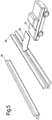
- Figure 3 shows a series of three stages wherein a vehicle 22 approaches an example of the security barrier 2 according to the present invention from substantially parallel to it.
- the same vehicle 22 is travelling substantially in parallel to the security barrier 2.
- the same vehicle 22 is adjacent to the security barrier 2.
- the wheels 24 on one side of the same vehicle 22 have mounted the lower inwardly-facing surface 14a.
- the weight of the vehicle 22 has compressed the material of the security barrier 2 causing the upper inwardly-facing surface 14b to fold inwards towards the wheels 24 of the vehicle 22.
- the compression of the material of the security barrier 2 and the inward folding causes the upper inwardly-facing surface 14b to engage with the wheels 24 of the vehicle 22, slowing the vehicle 22.
- Figure 4 shows a series of four stages wherein a vehicle 22 approaches at a fairly low speed a security barrier 2 according to the present invention from substantially perpendicular to it.
- Figure 4a shows the vehicle 22 a short distance away from the security barrier 2.
- Figure 4b shows the front wheels 24 about to engage the security barrier 2.
- Figure 4c shows the vehicle 22 mounting the security barrier 2.
- the front wheels 24 have mounted the lower inwardly-facing surface 14a of the security barrier 2.
- the nose 26 of the vehicle has engaged with the upper inwardly-facing surface 14b of the security barrier 2.
- the momentum of the vehicle 22 causes the upper inwardly-facing surface 14b of the security barrier 2 to deform to increase the angle between the upper inwardly-facing surface 14b and the lower inwardly-facing surface 14a.
- Figure 4d shows the situation shortly after the vehicle 22 has engaged with the security barrier 2. Because of the resilience of the material used to construct the security barrier 2, the upper inwardly-facing surface 14b has exerted a force on the nose 26 of the vehicle 22 to slow the vehicle 22 and to cause it to reverse course away from the security barrier 22.
- Figure 5 shows a first barrier 2a and a second barrier 2b according to the present invention.
- Barrier 2a faces outward in respect of the direction of vehicular approach 28.
- Barrier 2b faces inward in respect of the direction of vehicular approach 28.
- a vehicle 22 approaches the first barrier 2a in a direction 28 perpendicular to the first barrier 2a.
- Figure 6 shows the same first barrier 2a and second barrier 2b and vehicle 22 as in Figure 5 , after the vehicle 22 has overcome the first barrier 2a.
- the first barrier 2a has rolled in the direction 28 of vehicular approach.
- the vehicle 22 is now between the first barrier 2a and the second barrier 2b.
- the vehicle 22 has not been completely stopped by the first barrier 2a. However it does not have enough momentum to overcome the second barrier 2b.
- the second barrier 2b is deformed by the impact. The resilience of the material of the barriers enables the second barrier 2b to return a force back onto the vehicle 22 to assist in stopping it.
- Figure 7 shows a security barrier 2 with a fence element 30 attached to its top.
Landscapes
- Engineering & Computer Science (AREA)
- Architecture (AREA)
- Civil Engineering (AREA)
- Structural Engineering (AREA)
- Refuge Islands, Traffic Blockers, Or Guard Fence (AREA)
Description
- The present invention relates to a barrier for use in or near roadways with the aim of preventing vehicles from crossing a threshold.
- Previously disclosed security barriers comprise a concrete or brick wall or a resilient metal strip. Such barriers can be found at the sides of roads or in central reservations or at the perimeters of sites which are to be protected from attack.
- Existing barriers of the construction described above have two major disadvantages: they require a lot of time, preparation and materials to install; and because of their strength can cause significant damage to a vehicle that impacts upon them. Previously proposed vehicle barriers are described in
DE-U-20204649 ,WO2007/104304 ,EP-A-0,343,091 andUS4,982,931 . - It is an aim of the present invention to provide a security barrier for use on or near a roadway which can be installed quickly and easily.
- It is a further aim of the present invention to provide a security barrier for use on or near a roadway which minimises the damage caused to vehicles and the occupants of vehicles which impact upon the barrier.
- Accordingly the present invention is directed to a security barrier as set out in Claim 1. Further advantageous features are set out in the subsequent claims. Such a barrier is constructed from an elastomeric material, comprising two elongate elements, substantially equal in width, connected together substantially edge to edge to form a barrier with a substantially perpendicular or V-shaped cross-section.
- Preferably, the elastomeric material is a natural or man-made rubber.
- In a preferred embodiment, the rubber is reclaimed rubber from vehicle tyres.
- Advantageously, the angle between the elongate elements is chosen such that the centre of mass of the security barrier lies above the lower of the two elongate elements.
- Preferably, the angle between the elongate elements is substantially a right angle. A right angle between the elongate elements provides the advantage of good stability.
- In a preferred embodiment, one or both of the inwardly-facing surfaces of the elongate elements is concave in the region nearest the connection between them and convex in the region furthest away from the connection between them.
- Advantageously, one or both of the outwardly-facing surfaces of the elongate elements is convex in the region nearest the connection between them and concave in the region furthest away from the connection between them.
- Preferably, the region of the connection between the two elongate elements has a convex outer surface and a concave inner surface.
- This configuration provides stability once the security barrier is in the desired position because the barrier rests on the ground on two parts of the lower of the elongate elements. Because the parts of the elongate element near the ground form an arched profile the barrier can rest stably on uneven or contoured ground.
- The arched profile also allows for deformation during a vehicle impact, enabling the barrier to remain in frictional contact with the ground so as to minimise the displacement of the barrier caused by the vehicle impact.
- In a preferred embodiment, the part of the elongate elements furthest away from the connection between the elongate elements may have a cross section which forms a section of a circle.
- The configuration also enables the barrier to be light relative to previously disclosed barriers.
- Advantageously, the security barrier is constructed in sections, the sections may be joined by a joining means.
- Preferably, the joining means is one or more chains or ropes or rods passed through one or more openings within the barrier.
- Alternatively, the joining means is one or more chains or ropes or rods attached externally to the barrier.
- In a first mode of use, the security barrier is arranged so that the lower elongate element faces outwards towards potentially oncoming vehicles.
- If a vehicle impacts the barrier substantially in parallel with it, the vehicle will bounce back away from the barrier to rejoin the roadway or the vehicle's wheels will become trapped between the elongate elements so that the vehicle then continues in parallel with the barrier before coming to a halt. The downward force provided by the vehicle's wheel or wheels may deform the barrier generating friction between the barrier and the wheel or wheels of the vehicle, slowing the vehicle.
- In a second mode of use, the security barrier is arranged so that the lower elongate element faces inwards away from potentially oncoming vehicles, and the upper elongate faces outwards towards potentially oncoming vehicles.
- If a vehicle impacts the barrier with a significant momentum perpendicular to the barrier, the barrier will roll in the direction of the vehicle's momentum. The size of the security barrier will be chosen so as to suit the likely size and speed of potentially-impacting vehicles. In most cases the vehicle will come to a stop with the security barrier underneath the vehicle. This limits further movement by the impacting vehicle.
- In a third mode of usage, not forming part of the invention, the security barrier is arranged so that both elongate elements rest on the ground to form an inverted V-shape.
- In any of the three usage modes, if a vehicle impacts the barrier substantially perpendicular to it and with sufficient momentum, the vehicle may proceed fully over the top of the barrier. It is likely in this situation that the barrier will roll in the direction of travel of the impacting vehicle. The vehicle is likely to have lost a significant proportion of its momentum during this process. Therefore a second barrier may be arranged at a distance preferably more than the length of the vehicle behind the first barrier relative to the direction of vehicle approach. Therefore if the first barrier has reduced the vehicle's momentum sufficiently, the vehicle will not proceed fully over the top of the second barrier. The distance between the barriers is unlikely to be sufficient to enable the vehicle to build up sufficient momentum to get over the second barrier nor to reverse back over the first barrier. Therefore the vehicle should now be trapped between the two barriers. Accordingly, another aspect of the present invention is directed to the use of a first and second barrier, each according to the present invention, arranged substantially in parallel a distance apart from each other.
- The two barriers may be arranged so that the first barrier is outwardly facing and the second barrier is inwardly facing in respect of the likely direction of vehicular approach.
An embodiment of the present invention may have an elongate member width of approximately 450-500 mm. This size may be suitable for use in town centres and for vehicles travelling at approximately 15-20 miles per hour (24 - 32 km/h). - This or any other embodiment may further comprise fixings in order to incorporate fencing.
- An embodiment for use with higher speed vehicles on main roads may have an elongate member width of approximately 800-850 mm.
- This invention has particular application to the security field.
- In this field previous barriers had the disadvantage that they can be breached by fast moving vehicles due to nature of the materials from which these barriers are constructed. Furthermore often when an attack is conducted with vehicle borne improvised explosive devices a first vehicle is sent through to create a breach for a second vehicle to pass through. Finally, when a vehicle is exploded in close proximity to a concrete barrier, the barrier may disintegrate and provide extra flying debris which will injure people in the immediate vicinity.
- It is an aim of the present invention to provide a solution to this.
- The barrier of the present invention is of an elastomeric material. This provides the advantage that upon explosion any flying material created is of a softer nature. Furthermore due to the resilience of the elastomeric material in tests it has been found that such material does not disintegrate upon explosion and the barriers remain intact. This provides the further advantage that if a two vehicle packet is used to attack a facility, the barrier is not destroyed by the first vehicle in the packet, and the barrier remains intact against the second vehicle. Furthermore if the barrier is used in the method described in the application in a two barrier chain, the first barrier removes the speed and the second barrier due to the nature of it being linked provides the stopping power for the residual momentum of the vehicle. It has been found upon tests that once the first vehicle has been destroyed the barrier remains sufficiently in tact to stop a second vehicle which is attempting to breach the barrier.
- An embodiment of the present invention will now be described with reference to the accompanying drawings in which:
-
Figure 1 is a perspective view of a portion of a security barrier according to the present invention; -
Figure 2 is a cross-sectional view of a portion of a security barrier according to the present invention; -
Figure 3 shows an example of a situation of a vehicle coming into parallel contact with a security barrier according to the present invention; -
Figure 4 shows an example of a situation of a vehicle coming into perpendicular contact with a security barrier according to the present invention; -
Figure 5 shows an example of a configuration of two security barriers according to the present invention arranged in parallel; and -
Figure 6 shows the same configuration asFigure 5 with a vehicle having overcome the first barrier. -
Figure 7 shows a security barrier according to the present invention further incorporating a fence element. -
Figure 1 shows a portion of asecurity barrier 2 according to the present invention, comprising two parallelelongate elements 10, with edges joined atconnection 12. The angle betweenelongate elements 10 is approximately ninety degrees. The inwardly-facingsurfaces 14 of eachelongate element 10 are tightly concave near theconnection 12 and convex further away from theconnection 12. The outwardly-facingsurfaces 16 of eachelongate element 10 is convex near theconnection 12 and concave further away from theconnection 12. The interface between the inwardly-facing and outwardly-facing surfaces of eachelongate element 10 form a tightly-curvingconvex surface 18. Portions ofsecurity barrier 2 can be joined together by inserting a chain, rope, rod or any other suitable joining means through bores 20.Bores 20 are substantially cylindrical and have a diameter chosen to suit the chosen joining means.Bores 20 may be located near theconnection 12 and near the part of theelongate elements 10 furthest away from theconnection 12. Joining the portions of asecurity barrier 2 with more than one joining means results in greater stability of the security barrier as a whole. -
Figure 2 shows a portion of asecurity barrier 2 according to the present invention, comprising two parallelelongate elements 10, joined atconnection 12. The angle betweenelongate elements 10 is approximately ninety degrees. The inwardly-facingsurfaces 14 of eachelongate element 10 are tightly concave near theconnection 12 and convex further away from theconnection 12. The outwardly-facingsurfaces 16 of eachelongate element 10 is convex near theconnection 12 and concave further away from theconnection 12. The interface between the inwardly-facing and outwardly-facing surfaces of eachelongate element 10 form a tightly-curvingconvex surface 18. Portions ofsecurity barrier 2 can be joined together by inserting a chain, rope, rod or any other suitable joining means through bores 20.Bores 20 are substantially cylindrical and have a diamter chosen to suit the chosen joining means.Bores 20 may be located near theconnection 12 and near the part of theelongate elements 10 furthest away from theconnection 12. Joining the portions of asecurity barrier 2 with more than one joining means results in greater stability of the security barrier as a whole. -
Figure 3 shows a series of three stages wherein avehicle 22 approaches an example of thesecurity barrier 2 according to the present invention from substantially parallel to it. InFigure 3a thesame vehicle 22 is travelling substantially in parallel to thesecurity barrier 2. InFigure 3b thesame vehicle 22 is adjacent to thesecurity barrier 2. InFigure 3c thewheels 24 on one side of thesame vehicle 22 have mounted the lower inwardly-facingsurface 14a. The weight of thevehicle 22 has compressed the material of thesecurity barrier 2 causing the upper inwardly-facingsurface 14b to fold inwards towards thewheels 24 of thevehicle 22. The compression of the material of thesecurity barrier 2 and the inward folding causes the upper inwardly-facingsurface 14b to engage with thewheels 24 of thevehicle 22, slowing thevehicle 22. -
Figure 4 shows a series of four stages wherein avehicle 22 approaches at a fairly low speed asecurity barrier 2 according to the present invention from substantially perpendicular to it. -
Figure 4a shows the vehicle 22 a short distance away from thesecurity barrier 2. -
Figure 4b shows thefront wheels 24 about to engage thesecurity barrier 2. -
Figure 4c shows thevehicle 22 mounting thesecurity barrier 2. Thefront wheels 24 have mounted the lower inwardly-facingsurface 14a of thesecurity barrier 2. At the same time thenose 26 of the vehicle has engaged with the upper inwardly-facingsurface 14b of thesecurity barrier 2. The momentum of thevehicle 22 causes the upper inwardly-facingsurface 14b of thesecurity barrier 2 to deform to increase the angle between the upper inwardly-facingsurface 14b and the lower inwardly-facingsurface 14a. -
Figure 4d shows the situation shortly after thevehicle 22 has engaged with thesecurity barrier 2. Because of the resilience of the material used to construct thesecurity barrier 2, the upper inwardly-facingsurface 14b has exerted a force on thenose 26 of thevehicle 22 to slow thevehicle 22 and to cause it to reverse course away from thesecurity barrier 22. -
Figure 5 shows afirst barrier 2a and asecond barrier 2b according to the present invention.Barrier 2a faces outward in respect of the direction ofvehicular approach 28.Barrier 2b faces inward in respect of the direction ofvehicular approach 28. Avehicle 22 approaches thefirst barrier 2a in adirection 28 perpendicular to thefirst barrier 2a. -
Figure 6 shows the samefirst barrier 2a andsecond barrier 2b andvehicle 22 as inFigure 5 , after thevehicle 22 has overcome thefirst barrier 2a. Thefirst barrier 2a has rolled in thedirection 28 of vehicular approach. Thevehicle 22 is now between thefirst barrier 2a and thesecond barrier 2b. Thevehicle 22 has not been completely stopped by thefirst barrier 2a. However it does not have enough momentum to overcome thesecond barrier 2b. Thesecond barrier 2b is deformed by the impact. The resilience of the material of the barriers enables thesecond barrier 2b to return a force back onto thevehicle 22 to assist in stopping it. -
Figure 7 shows asecurity barrier 2 with afence element 30 attached to its top.
Claims (13)
- A security barrier (2) comprising two elongate elements (10), substantially equal in width, connected together edge to edge (12) to form a barrier (2) with a substantially perpendicular or V-shaped cross-section, wherein the outwardly-facing surfaces (16) of the elongate elements (10) form a deformable arched profile extending between two parts such that the security barrier (2) in an installed condition, rests on the ground on the two parts of the lower of the elongate members (10), characterized in that the security barrier (2) is constructed from an elastomeric material.
- A security barrier according to Claim 1 wherein the elastomeric material is natural or man-made rubber.
- A security barrier according to Claim 2 wherein the rubber is reclaimed rubber from vehicle tyres.
- A security barrier according to any preceding claim wherein the angle between the elongate elements (10)is chosen such that the centre of mass of the security barrier (2) lies above the lower of the two elongate elements (10).
- A security barrier (2) according to Claim 4 wherein the angle between the elongate elements (10) is substantially a right angle.
- A security barrier (2) according to any preceding claim wherein one or both of the inwardly-facing surfaces (14) of the elongate elements (10) is concave in the region nearest the connection (12) between them and convex in the region (18) furthest away from the connection (12) between them.
- A security barrier (2) according to any preceding claim wherein the region of the connection (12) between the two elongate elements (10) has a convex outer surface (16) and a concave inner surface (14).
- A security barrier (2) according to any preceding claim wherein the part (18) of the elongate elements (10) furthest away from the connection between (12) the elongate elements (10) have a cross section which forms a section of a circle.
- A security barrier (2) according to any preceding claim wherein the security barrier (2) is constructed in sections, the sections may be joined by a joining means.
- A security barrier (2) according to Claim 9 wherein the joining means is one or more chains or ropes or rods passed through one or more openings (20) within the barrier (2).
- A security barrier (2) according to Claim 9 wherein the joining means is one or more chains or ropes or rods attached externally to the barrier (2).
- A security barrier (2) according to any preceding Claim in which the width of the elongate elements (10) is substantially between 800 mm and 850 mm.
- A security barrier (2) according to any of Claims 1 to 11 in which the width of the elongate elements (10) is substantially between 450 mm and 500 mm.
Applications Claiming Priority (3)
| Application Number | Priority Date | Filing Date | Title |
|---|---|---|---|
| GB201116723A GB201116723D0 (en) | 2011-09-28 | 2011-09-28 | A security barrier |
| GBGB1116730.1A GB201116730D0 (en) | 2011-09-28 | 2011-09-28 | A security barrier |
| PCT/GB2012/052369 WO2013045910A1 (en) | 2011-09-28 | 2012-09-25 | A security barrier |
Publications (2)
| Publication Number | Publication Date |
|---|---|
| EP2761093A1 EP2761093A1 (en) | 2014-08-06 |
| EP2761093B1 true EP2761093B1 (en) | 2017-05-10 |
Family
ID=47076258
Family Applications (1)
| Application Number | Title | Priority Date | Filing Date |
|---|---|---|---|
| EP12778370.2A Active EP2761093B1 (en) | 2011-09-28 | 2012-09-25 | A security barrier |
Country Status (2)
| Country | Link |
|---|---|
| EP (1) | EP2761093B1 (en) |
| WO (1) | WO2013045910A1 (en) |
Families Citing this family (4)
| Publication number | Priority date | Publication date | Assignee | Title |
|---|---|---|---|---|
| AT514583B1 (en) * | 2013-11-29 | 2015-02-15 | Kirchdorfer Fertigteilholding Gmbh | Concrete wall element |
| CN104404900B (en) * | 2014-09-28 | 2016-04-27 | 嘉兴日名环交通安全设备有限公司 | Lugs and parking method |
| WO2018046960A1 (en) | 2016-09-12 | 2018-03-15 | Rosehill Polymers Group Limited | Barrier |
| RS67761B1 (en) * | 2017-07-18 | 2026-03-31 | Amos Klein | Rolling barrier system |
Citations (1)
| Publication number | Priority date | Publication date | Assignee | Title |
|---|---|---|---|---|
| EP0343091A1 (en) * | 1988-05-20 | 1989-11-23 | Claude Pomero | Method and devices for keeping vehicles on the road |
Family Cites Families (4)
| Publication number | Priority date | Publication date | Assignee | Title |
|---|---|---|---|---|
| DE20204649U1 (en) * | 2002-03-22 | 2002-06-06 | Lüft, Peter, 55257 Budenheim | Mobile element for use in traffic |
| JP4461330B2 (en) * | 2004-11-05 | 2010-05-12 | 株式会社花井製作所 | Vehicle forced stop device and vehicle forced stop method using the device |
| GB2434595A (en) * | 2006-01-27 | 2007-08-01 | Victor Joseph Wigley | Fence or barrier using water as ballast |
| WO2007104304A1 (en) * | 2006-03-10 | 2007-09-20 | Bilgutex A/S | Device for braking vehicles |
-
2012
- 2012-09-25 EP EP12778370.2A patent/EP2761093B1/en active Active
- 2012-09-25 WO PCT/GB2012/052369 patent/WO2013045910A1/en not_active Ceased
Patent Citations (2)
| Publication number | Priority date | Publication date | Assignee | Title |
|---|---|---|---|---|
| EP0343091A1 (en) * | 1988-05-20 | 1989-11-23 | Claude Pomero | Method and devices for keeping vehicles on the road |
| US4982931A (en) * | 1988-05-20 | 1991-01-08 | Pomero Claude A | Process and devices for retaining vehicles on a highway |
Also Published As
| Publication number | Publication date |
|---|---|
| WO2013045910A1 (en) | 2013-04-04 |
| EP2761093A1 (en) | 2014-08-06 |
Similar Documents
| Publication | Publication Date | Title |
|---|---|---|
| EP2384381B1 (en) | Post | |
| JP5962991B2 (en) | Guard fence and installation method of guard fence | |
| EP2646624B1 (en) | Impact attenuator for vehicles | |
| EP2761093A1 (en) | A security barrier | |
| CN112211135B (en) | Energy-absorbing impact-resistant road guardrail for smart city | |
| KR101445347B1 (en) | A crash cushion equipment using fracture splitting | |
| CN206376209U (en) | Highway guard rail | |
| KR101134563B1 (en) | Guard rail | |
| KR20110068698A (en) | Guardrail | |
| CN204753452U (en) | Highway security isolation area | |
| KR101191896B1 (en) | Guard fence for vehicle | |
| EA031844B1 (en) | Street pole | |
| KR101073539B1 (en) | Vehicle Collision Shock Absorber | |
| RU2434763C2 (en) | Front damping automotive guard and damping cartridge for it | |
| JP3206070U (en) | Climbing guardrail | |
| KR20110031554A (en) | Guard fence with cushioning function | |
| KR200274017Y1 (en) | Guard rail for absorbing shock | |
| KR101010003B1 (en) | Vehicle road departure prevention device | |
| KR101351445B1 (en) | a buffer for collision | |
| RU2548630C1 (en) | Motor road barrier | |
| KR101130570B1 (en) | Protective fence of road for bicycle | |
| RU2601825C1 (en) | End section of road barrier guard | |
| KR100386860B1 (en) | Shock absorbing device using waste tires | |
| KR20100092567A (en) | Bollad | |
| JP7480022B2 (en) | Vehicle capture device, cover member, and vehicle capture method |
Legal Events
| Date | Code | Title | Description |
|---|---|---|---|
| PUAI | Public reference made under article 153(3) epc to a published international application that has entered the european phase |
Free format text: ORIGINAL CODE: 0009012 |
|
| 17P | Request for examination filed |
Effective date: 20140428 |
|
| AK | Designated contracting states |
Kind code of ref document: A1 Designated state(s): AL AT BE BG CH CY CZ DE DK EE ES FI FR GB GR HR HU IE IS IT LI LT LU LV MC MK MT NL NO PL PT RO RS SE SI SK SM TR |
|
| DAX | Request for extension of the european patent (deleted) | ||
| 17Q | First examination report despatched |
Effective date: 20150821 |
|
| GRAP | Despatch of communication of intention to grant a patent |
Free format text: ORIGINAL CODE: EPIDOSNIGR1 |
|
| INTG | Intention to grant announced |
Effective date: 20160705 |
|
| STAA | Information on the status of an ep patent application or granted ep patent |
Free format text: STATUS: GRANT OF PATENT IS INTENDED |
|
| GRAS | Grant fee paid |
Free format text: ORIGINAL CODE: EPIDOSNIGR3 |
|
| GRAA | (expected) grant |
Free format text: ORIGINAL CODE: 0009210 |
|
| STAA | Information on the status of an ep patent application or granted ep patent |
Free format text: STATUS: THE PATENT HAS BEEN GRANTED |
|
| AK | Designated contracting states |
Kind code of ref document: B1 Designated state(s): AL AT BE BG CH CY CZ DE DK EE ES FI FR GB GR HR HU IE IS IT LI LT LU LV MC MK MT NL NO PL PT RO RS SE SI SK SM TR |
|
| REG | Reference to a national code |
Ref country code: GB Ref legal event code: FG4D |
|
| REG | Reference to a national code |
Ref country code: AT Ref legal event code: REF Ref document number: 892456 Country of ref document: AT Kind code of ref document: T Effective date: 20170515 Ref country code: CH Ref legal event code: EP |
|
| REG | Reference to a national code |
Ref country code: IE Ref legal event code: FG4D |
|
| REG | Reference to a national code |
Ref country code: DE Ref legal event code: R096 Ref document number: 602012032305 Country of ref document: DE |
|
| REG | Reference to a national code |
Ref country code: NL Ref legal event code: FP |
|
| REG | Reference to a national code |
Ref country code: LT Ref legal event code: MG4D |
|
| REG | Reference to a national code |
Ref country code: FR Ref legal event code: PLFP Year of fee payment: 6 |
|
| REG | Reference to a national code |
Ref country code: AT Ref legal event code: MK05 Ref document number: 892456 Country of ref document: AT Kind code of ref document: T Effective date: 20170510 |
|
| REG | Reference to a national code |
Ref country code: GB Ref legal event code: 732E Free format text: REGISTERED BETWEEN 20170921 AND 20170927 |
|
| PG25 | Lapsed in a contracting state [announced via postgrant information from national office to epo] |
Ref country code: FI Free format text: LAPSE BECAUSE OF FAILURE TO SUBMIT A TRANSLATION OF THE DESCRIPTION OR TO PAY THE FEE WITHIN THE PRESCRIBED TIME-LIMIT Effective date: 20170510 Ref country code: HR Free format text: LAPSE BECAUSE OF FAILURE TO SUBMIT A TRANSLATION OF THE DESCRIPTION OR TO PAY THE FEE WITHIN THE PRESCRIBED TIME-LIMIT Effective date: 20170510 Ref country code: ES Free format text: LAPSE BECAUSE OF FAILURE TO SUBMIT A TRANSLATION OF THE DESCRIPTION OR TO PAY THE FEE WITHIN THE PRESCRIBED TIME-LIMIT Effective date: 20170510 Ref country code: AT Free format text: LAPSE BECAUSE OF FAILURE TO SUBMIT A TRANSLATION OF THE DESCRIPTION OR TO PAY THE FEE WITHIN THE PRESCRIBED TIME-LIMIT Effective date: 20170510 Ref country code: NO Free format text: LAPSE BECAUSE OF FAILURE TO SUBMIT A TRANSLATION OF THE DESCRIPTION OR TO PAY THE FEE WITHIN THE PRESCRIBED TIME-LIMIT Effective date: 20170810 Ref country code: GR Free format text: LAPSE BECAUSE OF FAILURE TO SUBMIT A TRANSLATION OF THE DESCRIPTION OR TO PAY THE FEE WITHIN THE PRESCRIBED TIME-LIMIT Effective date: 20170811 Ref country code: LT Free format text: LAPSE BECAUSE OF FAILURE TO SUBMIT A TRANSLATION OF THE DESCRIPTION OR TO PAY THE FEE WITHIN THE PRESCRIBED TIME-LIMIT Effective date: 20170510 |
|
| PG25 | Lapsed in a contracting state [announced via postgrant information from national office to epo] |
Ref country code: PL Free format text: LAPSE BECAUSE OF FAILURE TO SUBMIT A TRANSLATION OF THE DESCRIPTION OR TO PAY THE FEE WITHIN THE PRESCRIBED TIME-LIMIT Effective date: 20170510 Ref country code: BG Free format text: LAPSE BECAUSE OF FAILURE TO SUBMIT A TRANSLATION OF THE DESCRIPTION OR TO PAY THE FEE WITHIN THE PRESCRIBED TIME-LIMIT Effective date: 20170810 Ref country code: IS Free format text: LAPSE BECAUSE OF FAILURE TO SUBMIT A TRANSLATION OF THE DESCRIPTION OR TO PAY THE FEE WITHIN THE PRESCRIBED TIME-LIMIT Effective date: 20170910 Ref country code: RS Free format text: LAPSE BECAUSE OF FAILURE TO SUBMIT A TRANSLATION OF THE DESCRIPTION OR TO PAY THE FEE WITHIN THE PRESCRIBED TIME-LIMIT Effective date: 20170510 Ref country code: SE Free format text: LAPSE BECAUSE OF FAILURE TO SUBMIT A TRANSLATION OF THE DESCRIPTION OR TO PAY THE FEE WITHIN THE PRESCRIBED TIME-LIMIT Effective date: 20170510 Ref country code: LV Free format text: LAPSE BECAUSE OF FAILURE TO SUBMIT A TRANSLATION OF THE DESCRIPTION OR TO PAY THE FEE WITHIN THE PRESCRIBED TIME-LIMIT Effective date: 20170510 |
|
| RAP2 | Party data changed (patent owner data changed or rights of a patent transferred) |
Owner name: ROSEHILL POLYMERS GROUP LIMITED |
|
| REG | Reference to a national code |
Ref country code: NL Ref legal event code: PD Owner name: ROSEHILL POLYMERS GROUP LIMITED; GB Free format text: DETAILS ASSIGNMENT: CHANGE OF OWNER(S), ASSIGNMENT; FORMER OWNER NAME: DYVERSE INNOVATION LIMITED Effective date: 20171024 |
|
| PG25 | Lapsed in a contracting state [announced via postgrant information from national office to epo] |
Ref country code: RO Free format text: LAPSE BECAUSE OF FAILURE TO SUBMIT A TRANSLATION OF THE DESCRIPTION OR TO PAY THE FEE WITHIN THE PRESCRIBED TIME-LIMIT Effective date: 20170510 Ref country code: SK Free format text: LAPSE BECAUSE OF FAILURE TO SUBMIT A TRANSLATION OF THE DESCRIPTION OR TO PAY THE FEE WITHIN THE PRESCRIBED TIME-LIMIT Effective date: 20170510 Ref country code: EE Free format text: LAPSE BECAUSE OF FAILURE TO SUBMIT A TRANSLATION OF THE DESCRIPTION OR TO PAY THE FEE WITHIN THE PRESCRIBED TIME-LIMIT Effective date: 20170510 Ref country code: CZ Free format text: LAPSE BECAUSE OF FAILURE TO SUBMIT A TRANSLATION OF THE DESCRIPTION OR TO PAY THE FEE WITHIN THE PRESCRIBED TIME-LIMIT Effective date: 20170510 Ref country code: DK Free format text: LAPSE BECAUSE OF FAILURE TO SUBMIT A TRANSLATION OF THE DESCRIPTION OR TO PAY THE FEE WITHIN THE PRESCRIBED TIME-LIMIT Effective date: 20170510 |
|
| REG | Reference to a national code |
Ref country code: DE Ref legal event code: R097 Ref document number: 602012032305 Country of ref document: DE |
|
| REG | Reference to a national code |
Ref country code: DE Ref legal event code: R082 Ref document number: 602012032305 Country of ref document: DE Representative=s name: MEISSNER BOLTE PATENTANWAELTE RECHTSANWAELTE P, DE Ref country code: DE Ref legal event code: R081 Ref document number: 602012032305 Country of ref document: DE Owner name: ROSEHILL POLYMERS GROUP LIMITED, SOWERBY BRIDG, GB Free format text: FORMER OWNER: DYVERSE INNOVATION LTD., CANEWDON, ESSEX, GB |
|
| PG25 | Lapsed in a contracting state [announced via postgrant information from national office to epo] |
Ref country code: IT Free format text: LAPSE BECAUSE OF FAILURE TO SUBMIT A TRANSLATION OF THE DESCRIPTION OR TO PAY THE FEE WITHIN THE PRESCRIBED TIME-LIMIT Effective date: 20170510 Ref country code: SM Free format text: LAPSE BECAUSE OF FAILURE TO SUBMIT A TRANSLATION OF THE DESCRIPTION OR TO PAY THE FEE WITHIN THE PRESCRIBED TIME-LIMIT Effective date: 20170510 |
|
| PLBE | No opposition filed within time limit |
Free format text: ORIGINAL CODE: 0009261 |
|
| STAA | Information on the status of an ep patent application or granted ep patent |
Free format text: STATUS: NO OPPOSITION FILED WITHIN TIME LIMIT |
|
| 26N | No opposition filed |
Effective date: 20180213 |
|
| REG | Reference to a national code |
Ref country code: CH Ref legal event code: PL |
|
| PG25 | Lapsed in a contracting state [announced via postgrant information from national office to epo] |
Ref country code: SI Free format text: LAPSE BECAUSE OF FAILURE TO SUBMIT A TRANSLATION OF THE DESCRIPTION OR TO PAY THE FEE WITHIN THE PRESCRIBED TIME-LIMIT Effective date: 20170510 Ref country code: MC Free format text: LAPSE BECAUSE OF FAILURE TO SUBMIT A TRANSLATION OF THE DESCRIPTION OR TO PAY THE FEE WITHIN THE PRESCRIBED TIME-LIMIT Effective date: 20170510 |
|
| REG | Reference to a national code |
Ref country code: IE Ref legal event code: MM4A |
|
| REG | Reference to a national code |
Ref country code: BE Ref legal event code: MM Effective date: 20170930 |
|
| PG25 | Lapsed in a contracting state [announced via postgrant information from national office to epo] |
Ref country code: LU Free format text: LAPSE BECAUSE OF NON-PAYMENT OF DUE FEES Effective date: 20170925 |
|
| PG25 | Lapsed in a contracting state [announced via postgrant information from national office to epo] |
Ref country code: CH Free format text: LAPSE BECAUSE OF NON-PAYMENT OF DUE FEES Effective date: 20170930 Ref country code: IE Free format text: LAPSE BECAUSE OF NON-PAYMENT OF DUE FEES Effective date: 20170925 Ref country code: LI Free format text: LAPSE BECAUSE OF NON-PAYMENT OF DUE FEES Effective date: 20170930 |
|
| PG25 | Lapsed in a contracting state [announced via postgrant information from national office to epo] |
Ref country code: BE Free format text: LAPSE BECAUSE OF NON-PAYMENT OF DUE FEES Effective date: 20170930 |
|
| REG | Reference to a national code |
Ref country code: FR Ref legal event code: PLFP Year of fee payment: 7 |
|
| PG25 | Lapsed in a contracting state [announced via postgrant information from national office to epo] |
Ref country code: MT Free format text: LAPSE BECAUSE OF NON-PAYMENT OF DUE FEES Effective date: 20170925 |
|
| PG25 | Lapsed in a contracting state [announced via postgrant information from national office to epo] |
Ref country code: HU Free format text: LAPSE BECAUSE OF FAILURE TO SUBMIT A TRANSLATION OF THE DESCRIPTION OR TO PAY THE FEE WITHIN THE PRESCRIBED TIME-LIMIT; INVALID AB INITIO Effective date: 20120925 |
|
| PG25 | Lapsed in a contracting state [announced via postgrant information from national office to epo] |
Ref country code: CY Free format text: LAPSE BECAUSE OF NON-PAYMENT OF DUE FEES Effective date: 20170510 |
|
| PG25 | Lapsed in a contracting state [announced via postgrant information from national office to epo] |
Ref country code: MK Free format text: LAPSE BECAUSE OF FAILURE TO SUBMIT A TRANSLATION OF THE DESCRIPTION OR TO PAY THE FEE WITHIN THE PRESCRIBED TIME-LIMIT Effective date: 20170510 |
|
| PG25 | Lapsed in a contracting state [announced via postgrant information from national office to epo] |
Ref country code: TR Free format text: LAPSE BECAUSE OF FAILURE TO SUBMIT A TRANSLATION OF THE DESCRIPTION OR TO PAY THE FEE WITHIN THE PRESCRIBED TIME-LIMIT Effective date: 20170510 |
|
| PG25 | Lapsed in a contracting state [announced via postgrant information from national office to epo] |
Ref country code: PT Free format text: LAPSE BECAUSE OF FAILURE TO SUBMIT A TRANSLATION OF THE DESCRIPTION OR TO PAY THE FEE WITHIN THE PRESCRIBED TIME-LIMIT Effective date: 20170510 |
|
| PG25 | Lapsed in a contracting state [announced via postgrant information from national office to epo] |
Ref country code: AL Free format text: LAPSE BECAUSE OF FAILURE TO SUBMIT A TRANSLATION OF THE DESCRIPTION OR TO PAY THE FEE WITHIN THE PRESCRIBED TIME-LIMIT Effective date: 20170510 |
|
| P01 | Opt-out of the competence of the unified patent court (upc) registered |
Effective date: 20230525 |
|
| PGFP | Annual fee paid to national office [announced via postgrant information from national office to epo] |
Ref country code: NL Payment date: 20250925 Year of fee payment: 14 |
|
| PGFP | Annual fee paid to national office [announced via postgrant information from national office to epo] |
Ref country code: GB Payment date: 20250930 Year of fee payment: 14 |
|
| PGFP | Annual fee paid to national office [announced via postgrant information from national office to epo] |
Ref country code: FR Payment date: 20250925 Year of fee payment: 14 |
|
| PGFP | Annual fee paid to national office [announced via postgrant information from national office to epo] |
Ref country code: DE Payment date: 20251014 Year of fee payment: 14 |