EP2759727A2 - Method of manufacturing spline telescopic shaft - Google Patents
Method of manufacturing spline telescopic shaft Download PDFInfo
- Publication number
- EP2759727A2 EP2759727A2 EP14151552.8A EP14151552A EP2759727A2 EP 2759727 A2 EP2759727 A2 EP 2759727A2 EP 14151552 A EP14151552 A EP 14151552A EP 2759727 A2 EP2759727 A2 EP 2759727A2
- Authority
- EP
- European Patent Office
- Prior art keywords
- sliding
- load
- intermediate member
- manufacturing intermediate
- detected
- Prior art date
- Legal status (The legal status is an assumption and is not a legal conclusion. Google has not performed a legal analysis and makes no representation as to the accuracy of the status listed.)
- Granted
Links
Images


Classifications
-
- B—PERFORMING OPERATIONS; TRANSPORTING
- B05—SPRAYING OR ATOMISING IN GENERAL; APPLYING FLUENT MATERIALS TO SURFACES, IN GENERAL
- B05D—PROCESSES FOR APPLYING FLUENT MATERIALS TO SURFACES, IN GENERAL
- B05D1/00—Processes for applying liquids or other fluent materials
- B05D1/18—Processes for applying liquids or other fluent materials performed by dipping
-
- F—MECHANICAL ENGINEERING; LIGHTING; HEATING; WEAPONS; BLASTING
- F16—ENGINEERING ELEMENTS AND UNITS; GENERAL MEASURES FOR PRODUCING AND MAINTAINING EFFECTIVE FUNCTIONING OF MACHINES OR INSTALLATIONS; THERMAL INSULATION IN GENERAL
- F16C—SHAFTS; FLEXIBLE SHAFTS; ELEMENTS OR CRANKSHAFT MECHANISMS; ROTARY BODIES OTHER THAN GEARING ELEMENTS; BEARINGS
- F16C3/00—Shafts; Axles; Cranks; Eccentrics
- F16C3/02—Shafts; Axles
- F16C3/03—Shafts; Axles telescopic
- F16C3/035—Shafts; Axles telescopic with built-in bearings
-
- F—MECHANICAL ENGINEERING; LIGHTING; HEATING; WEAPONS; BLASTING
- F16—ENGINEERING ELEMENTS AND UNITS; GENERAL MEASURES FOR PRODUCING AND MAINTAINING EFFECTIVE FUNCTIONING OF MACHINES OR INSTALLATIONS; THERMAL INSULATION IN GENERAL
- F16C—SHAFTS; FLEXIBLE SHAFTS; ELEMENTS OR CRANKSHAFT MECHANISMS; ROTARY BODIES OTHER THAN GEARING ELEMENTS; BEARINGS
- F16C33/00—Parts of bearings; Special methods for making bearings or parts thereof
- F16C33/02—Parts of sliding-contact bearings
- F16C33/04—Brasses; Bushes; Linings
- F16C33/20—Sliding surface consisting mainly of plastics
- F16C33/208—Methods of manufacture, e.g. shaping, applying coatings
-
- F—MECHANICAL ENGINEERING; LIGHTING; HEATING; WEAPONS; BLASTING
- F16—ENGINEERING ELEMENTS AND UNITS; GENERAL MEASURES FOR PRODUCING AND MAINTAINING EFFECTIVE FUNCTIONING OF MACHINES OR INSTALLATIONS; THERMAL INSULATION IN GENERAL
- F16D—COUPLINGS FOR TRANSMITTING ROTATION; CLUTCHES; BRAKES
- F16D3/00—Yielding couplings, i.e. with means permitting movement between the connected parts during the drive
- F16D3/02—Yielding couplings, i.e. with means permitting movement between the connected parts during the drive adapted to specific functions
- F16D3/06—Yielding couplings, i.e. with means permitting movement between the connected parts during the drive adapted to specific functions specially adapted to allow axial displacement
-
- B—PERFORMING OPERATIONS; TRANSPORTING
- B05—SPRAYING OR ATOMISING IN GENERAL; APPLYING FLUENT MATERIALS TO SURFACES, IN GENERAL
- B05D—PROCESSES FOR APPLYING FLUENT MATERIALS TO SURFACES, IN GENERAL
- B05D1/00—Processes for applying liquids or other fluent materials
- B05D1/40—Distributing applied liquids or other fluent materials by members moving relatively to surface
-
- B—PERFORMING OPERATIONS; TRANSPORTING
- B05—SPRAYING OR ATOMISING IN GENERAL; APPLYING FLUENT MATERIALS TO SURFACES, IN GENERAL
- B05D—PROCESSES FOR APPLYING FLUENT MATERIALS TO SURFACES, IN GENERAL
- B05D7/00—Processes, other than flocking, specially adapted for applying liquids or other fluent materials to particular surfaces or for applying particular liquids or other fluent materials
- B05D7/22—Processes, other than flocking, specially adapted for applying liquids or other fluent materials to particular surfaces or for applying particular liquids or other fluent materials to internal surfaces, e.g. of tubes
-
- F—MECHANICAL ENGINEERING; LIGHTING; HEATING; WEAPONS; BLASTING
- F16—ENGINEERING ELEMENTS AND UNITS; GENERAL MEASURES FOR PRODUCING AND MAINTAINING EFFECTIVE FUNCTIONING OF MACHINES OR INSTALLATIONS; THERMAL INSULATION IN GENERAL
- F16C—SHAFTS; FLEXIBLE SHAFTS; ELEMENTS OR CRANKSHAFT MECHANISMS; ROTARY BODIES OTHER THAN GEARING ELEMENTS; BEARINGS
- F16C2326/00—Articles relating to transporting
- F16C2326/20—Land vehicles
- F16C2326/24—Steering systems, e.g. steering rods or columns
-
- F—MECHANICAL ENGINEERING; LIGHTING; HEATING; WEAPONS; BLASTING
- F16—ENGINEERING ELEMENTS AND UNITS; GENERAL MEASURES FOR PRODUCING AND MAINTAINING EFFECTIVE FUNCTIONING OF MACHINES OR INSTALLATIONS; THERMAL INSULATION IN GENERAL
- F16D—COUPLINGS FOR TRANSMITTING ROTATION; CLUTCHES; BRAKES
- F16D2250/00—Manufacturing; Assembly
- F16D2250/0038—Surface treatment
- F16D2250/0046—Coating
-
- F—MECHANICAL ENGINEERING; LIGHTING; HEATING; WEAPONS; BLASTING
- F16—ENGINEERING ELEMENTS AND UNITS; GENERAL MEASURES FOR PRODUCING AND MAINTAINING EFFECTIVE FUNCTIONING OF MACHINES OR INSTALLATIONS; THERMAL INSULATION IN GENERAL
- F16D—COUPLINGS FOR TRANSMITTING ROTATION; CLUTCHES; BRAKES
- F16D2250/00—Manufacturing; Assembly
- F16D2250/0092—Tools or machines for producing linings
-
- F—MECHANICAL ENGINEERING; LIGHTING; HEATING; WEAPONS; BLASTING
- F16—ENGINEERING ELEMENTS AND UNITS; GENERAL MEASURES FOR PRODUCING AND MAINTAINING EFFECTIVE FUNCTIONING OF MACHINES OR INSTALLATIONS; THERMAL INSULATION IN GENERAL
- F16D—COUPLINGS FOR TRANSMITTING ROTATION; CLUTCHES; BRAKES
- F16D2300/00—Special features for couplings or clutches
- F16D2300/10—Surface characteristics; Details related to material surfaces
Definitions
- the present invention relates to a method of manufacturing a spline telescopic shaft.
- JP-A-2011-38561 discloses that an inner shaft manufacturing intermediate member having male splines on which a first resin coating is formed, and an outer shaft manufacturing intermediate member in which female splines are formed are forcibly reciprocally slid in the axial direction under given conditions, to transfer a part of the resin material of the first resin coating to the female splines of the outer shaft manufacturing intermediate member, thereby forming a second resin coating.
- Conditions that the sliding load in the axial direction is not larger than a predetermined value, and that the play in the rotation direction is not larger than a predetermined amount are sometimes set as performances required in a spline telescopic shaft which is used as, for example, a steering shaft or intermediate shaft in a vehicle.
- a method of manufacturing a spline telescopic shaft comprising a sliding step of sliding in an axial direction an inner shaft manufacturing intermediate member and an outer shaft manufacturing intermediate member, in one of which a resin coating is disposed on splines, wherein, in the sliding step, a sliding load of the inner shaft manufacturing intermediate member and the outer shaft manufacturing intermediate member is detected, and sliding is ended at a timing when the detected sliding load reaches a threshold load which is determined based on an initial sliding load detected at a start of the sliding.
- the threshold load W1 may be obtained by using a monotonic increasing function in which the initial sliding load W0 is set as a parameter.
- the constant B may be increased or decreased in accordance with a degree of a slide stroke L of the inner shaft manufacturing intermediate member and the outer shaft manufacturing intermediate member in the sliding step.
- the constant B may be proportional to the slide stroke L.
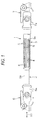
- Fig. 1 is a partially sectional side view of a spline telescopic shaft 1 which is produced by a manufacturing method of an embodiment of the invention.
- the spline telescopic shaft 1 is sometimes used as an intermediate shaft which is interposed between a steering shaft (not shown) and a pinion shaft (not shown) of a rack and pinion mechanism.
- the spline telescopic shaft 1 may be used as a steering shaft which contracts when absorbing a shock.
- the spline telescopic shaft 1 includes an inner shaft 2 and tubular outer shaft 3 which are fitted to each other.
- the inner shaft 2 and the outer shaft 3 are spline-fitted to each other in a slidable and torque-transmittable manner along the axial direction X1.
- a plurality of male splines 4 are disposed on the outer peripheral surface 2a of the inner shaft 2, and a plurality of female splines 5 which alternately mesh with the male splines 4 are disposed on the inner peripheral surface 3a of the outer shaft 3.
- the splines 4, 5 are diagrammatically shown.
- one yoke 6a of a universal joint 6 is integrally attached to one end of the inner shaft 2.
- One yoke 7a of a universal joint 7 is integrally attached to one end of the outer shaft 3.
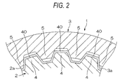
- a resin coating 40 is formed on the surfaces of the male splines 4.
- the resin coating 40 is formed by using a synthetic resin.
- the synthetic resin are a thermo plastic resin such as polyimide or polyacetal, and a thermo setting resin such as an epoxy resin.
- An inner shaft manufacturing intermediate member 20 in which a resin coating 41 is formed on the surfaces of the male splines 4 as shown in Fig. 3A , and an outer shaft manufacturing intermediate member 30 which has the female splines 5 as shown in Fig. 3B , and which is configured only by a metal are fitted to each other with a negative fitting space. Namely, the inner shaft manufacturing intermediate member 20 is press fit into the outer shaft manufacturing intermediate member 30.
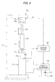
- the manufacturing intermediate members 20, 30 are attached to a vibrating apparatus 70 shown in Fig. 4 , and the shaped resin coating 40 is obtained through a sliding step in which the inner shaft manufacturing intermediate member 20 and the outer shaft manufacturing intermediate member 30 are forcibly slid in the axial direction X1.
- a torsional torque may be applied or may not be applied between the manufacturing intermediate members 20, 30.
- the vibrating apparatus 70 which is used in the sliding step includes: a stationary frame 71; a vibration actuator 72 (for example, a hydraulic cylinder) which is fixed to one end of the stationary frame 71; an extendable rod 73 which is extended from or contracted toward the vibration actuator 72; a first attachment bracket 74 which is attached to the tip end of the extendable rod 73; and a second attachment bracket 76 which is fixed to the other end of the stationary frame 71 via a load sensor 75.
- a vibration actuator 72 for example, a hydraulic cylinder
- Hydraulic fluid is supplied to the vibration actuator 72 via a hydraulic mechanism 79 which is connected to a hydraulic pump 77 and a hydraulic tank 78, whereby the extendable rod 73 is extended or contracted.
- one end of the outer shaft manufacturing intermediate member 30 is attached to the first attachment bracket 74 in the one end of the extendable rod 73 of the vibration actuator 72, and one end of the inner shaft manufacturing intermediate member 20 is fixed to the second attachment bracket 76 which is fixed to the load sensor 75.
- a position sensor 80 which detects the stroke position of the extendable rod 73 is disposed on the vibration actuator 72.
- the detection signals of the load sensor 75 and the position sensor 80 are supplied to a control device 81.
- the control device 81 Based on position information obtained by the position sensor 80 and speed information which is obtained by differentiating the position information, the control device 81 supplies a control signal to the hydraulic mechanism 79 to cause the extendable rod 73 to be extracted and contracted at a predetermined stroke and a predetermined rate.
- control device 81 receives the detection signal of the load sensor 75, detects a sliding load W based on the peak value of each vibration cycle, and, at the timing when the sliding load W satisfies predetermined conditions, ends the sliding step using the vibration actuator 72.
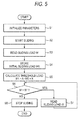
- step S1 parameters are initialized in step S1 upon activation of the system, and then the vibration actuator 72 is driven in step S2 to start the sliding.
- step S3 the control device 81 reads the sliding load W which is detected by the load sensor 75 immediately after the start of the sliding, and, in step S4, stores the read sliding load W as an initial sliding load W0.
- a threshold load W1 (kN) is calculated by using following linear function expression (1) based on the initial sliding load W0.
- W ⁇ 1 A ⁇ W ⁇ 0 + B
- step S6 it is determined in step S6 whether the sliding load W is larger than the threshold load W1 or not. If the sliding load W is larger than the threshold load W1 (YES in step S6), the system proceeds to step S7 to read the sliding load W.
- steps S6 and S7 are repeated until the sliding load W which is detected in step S7 is equal to or smaller than the threshold load W1 (W ⁇ W1). If the detected sliding load W is equal to or smaller than the threshold load W1 (NO in step S6), the system proceeds to step S8 to stop the sliding, thereby ending the process.
- the tooth profiles of the shafts 2, 3 are formed only by frictional heat generated by sliding of the inner shaft manufacturing intermediate member 20 and the outer shaft manufacturing intermediate member 30. Namely, a part of the resin material of the resin coating 41 of the inner shaft manufacturing intermediate member 20 is mutually rubbed with sliding regions of the female splines 5 of the outer shaft manufacturing intermediate member 30, whereby the resin coating 41 is formed as the resin coating 40 to complete the inner shaft 2. Moreover, the tooth profiles of the female splines of the outer shaft manufacturing intermediate member 30 are shaped by the mutual rubbing to complete the outer shaft 3.
- the sliding load W of the manufacturing intermediate members 20, 30 is detected, and the sliding is ended at the timing when the detected sliding load W reaches the threshold load W1 which is determined based on the initial sliding load W0 detected at the start of the sliding.
- the tooth profiles of the splines 4, 5 can be satisfactorily adapted to each other by matching of actual articles, with the result that, after completion, the spline telescopic shaft 1 in which the sliding load is small and the play is small can be realized in a state where the failure rate is low.
- the threshold load W1 at which the sliding step is to be ended is determined based on the initial sliding load W0 because of the following reason.
- the amount of heat per unit area and time which is generated when two members are slid against each other while being in contact with each other is proportional to the product of the coefficient of friction between the contact surfaces of the two members, the surface pressure at the contact surfaces, and the slip speed.
- the amount of heat per unit area and time which is generated due to the sliding adaptability is proportional to the product of the sliding load (corresponding to the product of the coefficient of friction and surface pressure which are described above) and the slip speed.
- the sliding load is reduced with the elapse of time as shown in Fig. 7 .
- the total of the amount of heat which is generated after the start of the sliding at an initial sliding load W0B and until the elapse of a sliding time t is proportional to the area of the hatched region in Fig. 7 .
- the case where the initial sliding load W0 at the start of the sliding in the sliding step is large is compared with that where the initial sliding load is small.
- the initial sliding load is W0B or large as indicated by the solid line in Fig. 7
- the amount of frictional heat generated by the sliding is great.
- the constant B may be increased or decreased in accordance with the degree of the slide stroke L of the manufacturing intermediate members 20, 30 in the sliding step.
- the generated frictional heat is relatively large, and hence an amount of heat (amount of energy) which is required to satisfactorily form the tooth profiles of the splines 4, 5 can be obtained even when the sliding is ended at the timing when the detected sliding load W reaches the threshold load W1 which is relatively large.
- the generated frictional heat is relatively small, and hence an amount of heat (amount of energy) which is required to satisfactorily form the tooth profiles of the splines 4, 5 can be obtained only after the sliding step is continued for a relatively long period until the timing when the detected sliding load W reaches the threshold load W1 which is relatively small.
- the constant B may be proportional to the slide stroke L.
- a constant B1 which is preferable in an unknown individual having the slide stroke L1 can be obtained by a calculation using following proportional expression (2).
- the threshold load W1 is obtained by using the linear function expression (1).
- the useful expression is not limited to a linear function expression.
- the resin coating 41 is disposed on the inner shaft manufacturing intermediate member 20.
- a resin coating may be disposed on the outer shaft manufacturing intermediate member.
- various changes can be made within the scope of the appended claims.
- the inventors found the followings.
- the amount of frictional heat generated by the sliding is great in the former case where the initial sliding load is large.
- the sliding load of the manufacturing intermediate members is detected, and the sliding is ended at a timing when the detected sliding load reaches the threshold load which is determined based on the initial sliding load detected at the start of the sliding.
- the threshold load W1 is expressed by a monotonic increasing function in which the initial sliding load W0 is set as a parameter, so that, when the initial sliding load W0 is relatively large, the threshold load W1 can be made relatively large, and, when the initial sliding load W0 is relatively small, the threshold load W1 can be made relatively small.
- the constant B is increased or decreased in accordance with the degree of the slide stroke L of the manufacturing intermediate members, and therefore a sliding step adequate for each individual can be realized.
- the generated frictional heat is relatively large, and hence an amount of heat (amount of energy) which is required to satisfactorily form the tooth profiles of the splines can be obtained even when the sliding is ended at a timing when the detected sliding load reaches a threshold load which is relatively large.
- the generated frictional heat is relatively small, and hence an amount of heat (amount of energy) which is required to satisfactorily form the tooth profiles of the splines can be obtained only after the sliding step is continued for a relatively long period until a timing when the detected sliding load reaches a threshold load which is relatively small.
- the unknown constant B1 which has not been experimentally obtained can be anticipated. Therefore, a sliding step adequate for each individual can be easily realized.
Landscapes
- Engineering & Computer Science (AREA)
- General Engineering & Computer Science (AREA)
- Mechanical Engineering (AREA)
- Manufacturing & Machinery (AREA)
- Ocean & Marine Engineering (AREA)
- Shafts, Cranks, Connecting Bars, And Related Bearings (AREA)
- Steering Controls (AREA)
- Vehicle Body Suspensions (AREA)
Abstract
Description
- The present invention relates to a method of manufacturing a spline telescopic shaft.
-
JP-A-2011-38561 - Conditions that the sliding load in the axial direction is not larger than a predetermined value, and that the play in the rotation direction is not larger than a predetermined amount are sometimes set as performances required in a spline telescopic shaft which is used as, for example, a steering shaft or intermediate shaft in a vehicle.
- Usually, there is a tendency that, when the sliding load is excessively reduced, the play in the rotation direction is large, and, when the play in the rotation direction is excessively reduced, conversely, the sliding load is large. Namely, it is difficult that the two performances are compatible.
- It is assumed that the sliding step disclosed in
JP-A-2011-38561 - It is an object of the invention to provide a method of manufacturing a spline telescopic shaft in which the failure rate is low.
- In order to achieve the object, according to the invention, there is provided a method of manufacturing a spline telescopic shaft, the method comprising a sliding step of sliding in an axial direction an inner shaft manufacturing intermediate member and an outer shaft manufacturing intermediate member, in one of which a resin coating is disposed on splines, wherein, in the sliding step, a sliding load of the inner shaft manufacturing intermediate member and the outer shaft manufacturing intermediate member is detected, and sliding is ended at a timing when the detected sliding load reaches a threshold load which is determined based on an initial sliding load detected at a start of the sliding.
- When the threshold load is W1 and the initial sliding load is W0, the threshold load W1 may be obtained by using a monotonic increasing function in which the initial sliding load W0 is set as a parameter.
- The threshold load W1 may be obtained by using a following linear function expression: W1 = A · W0 + B where A and B are constants, and the initial sliding load W0 is the parameter.
- The constant B may be increased or decreased in accordance with a degree of a slide stroke L of the inner shaft manufacturing intermediate member and the outer shaft manufacturing intermediate member in the sliding step.
- The constant B may be proportional to the slide stroke L.
-
-
Fig. 1 is a partially sectional side view of a spline telescopic shaft which is produced by a manufacturing method of an embodiment of the invention. -
Fig. 2 is a sectional view of main portions of the spline telescopic shaft. -
Fig. 3A is a schematic sectional view of an inner shaft manufacturing intermediate member which is coated by a resin coating. -
Fig. 3B is a schematic sectional view of an outer shaft manufacturing intermediate member. -
Fig. 4 is a diagram of a vibrating apparatus which is used in a sliding step. -
Fig. 5 is a flowchart of a control flow of controlling the vibrating apparatus. -
Fig. 6 is a graph showing a relationship between an initial sliding load W0 and a threshold load W1 at which the sliding step is ended. -
Fig. 7 is a graph showing a temporal change of a sliding load in the sliding step. - A preferred embodiment of the invention will be described with reference to the accompanying drawings.
-
Fig. 1 is a partially sectional side view of a splinetelescopic shaft 1 which is produced by a manufacturing method of an embodiment of the invention. For example, the splinetelescopic shaft 1 is sometimes used as an intermediate shaft which is interposed between a steering shaft (not shown) and a pinion shaft (not shown) of a rack and pinion mechanism. - Alternatively, the spline
telescopic shaft 1 may be used as a steering shaft which contracts when absorbing a shock. - The spline
telescopic shaft 1 includes aninner shaft 2 and tubularouter shaft 3 which are fitted to each other. Theinner shaft 2 and theouter shaft 3 are spline-fitted to each other in a slidable and torque-transmittable manner along the axial direction X1. - A plurality of
male splines 4 are disposed on the outerperipheral surface 2a of theinner shaft 2, and a plurality offemale splines 5 which alternately mesh with themale splines 4 are disposed on the innerperipheral surface 3a of theouter shaft 3. InFig. 1 , thesplines - In the case where the spline
telescopic shaft 1 constitutes an intermediate shaft, as shown inFig. 1 , oneyoke 6a of auniversal joint 6 is integrally attached to one end of theinner shaft 2. One yoke 7a of auniversal joint 7 is integrally attached to one end of theouter shaft 3. - As shown in
Fig. 2 , aresin coating 40 is formed on the surfaces of themale splines 4. Theresin coating 40 is formed by using a synthetic resin. Examples of the synthetic resin are a thermo plastic resin such as polyimide or polyacetal, and a thermo setting resin such as an epoxy resin. - An inner shaft manufacturing
intermediate member 20 in which aresin coating 41 is formed on the surfaces of themale splines 4 as shown inFig. 3A , and an outer shaft manufacturingintermediate member 30 which has thefemale splines 5 as shown inFig. 3B , and which is configured only by a metal are fitted to each other with a negative fitting space. Namely, the inner shaft manufacturingintermediate member 20 is press fit into the outer shaft manufacturingintermediate member 30. - Then, the manufacturing
intermediate members apparatus 70 shown inFig. 4 , and theshaped resin coating 40 is obtained through a sliding step in which the inner shaft manufacturingintermediate member 20 and the outer shaft manufacturingintermediate member 30 are forcibly slid in the axial direction X1. At the time when the manufacturingintermediate members intermediate members - The vibrating
apparatus 70 which is used in the sliding step includes: astationary frame 71; a vibration actuator 72 (for example, a hydraulic cylinder) which is fixed to one end of thestationary frame 71; anextendable rod 73 which is extended from or contracted toward thevibration actuator 72; afirst attachment bracket 74 which is attached to the tip end of theextendable rod 73; and a second attachment bracket 76 which is fixed to the other end of thestationary frame 71 via aload sensor 75. - Hydraulic fluid is supplied to the
vibration actuator 72 via ahydraulic mechanism 79 which is connected to ahydraulic pump 77 and ahydraulic tank 78, whereby theextendable rod 73 is extended or contracted. - For example, one end of the outer shaft manufacturing
intermediate member 30 is attached to thefirst attachment bracket 74 in the one end of theextendable rod 73 of thevibration actuator 72, and one end of the inner shaft manufacturingintermediate member 20 is fixed to the second attachment bracket 76 which is fixed to theload sensor 75. - A
position sensor 80 which detects the stroke position of theextendable rod 73 is disposed on thevibration actuator 72. The detection signals of theload sensor 75 and theposition sensor 80 are supplied to acontrol device 81. Based on position information obtained by theposition sensor 80 and speed information which is obtained by differentiating the position information, thecontrol device 81 supplies a control signal to thehydraulic mechanism 79 to cause theextendable rod 73 to be extracted and contracted at a predetermined stroke and a predetermined rate. - Moreover, the
control device 81 receives the detection signal of theload sensor 75, detects a sliding load W based on the peak value of each vibration cycle, and, at the timing when the sliding load W satisfies predetermined conditions, ends the sliding step using thevibration actuator 72. - As shown in the flowchart of
Fig. 5 , specifically, parameters are initialized in step S1 upon activation of the system, and then thevibration actuator 72 is driven in step S2 to start the sliding. - In step S3, the
control device 81 reads the sliding load W which is detected by theload sensor 75 immediately after the start of the sliding, and, in step S4, stores the read sliding load W as an initial sliding load W0. - In step S5, then, a threshold load W1 (kN) is calculated by using following linear function expression (1) based on the initial sliding load W0.

- Then, it is determined in step S6 whether the sliding load W is larger than the threshold load W1 or not. If the sliding load W is larger than the threshold load W1 (YES in step S6), the system proceeds to step S7 to read the sliding load W.
- The processes of steps S6 and S7 are repeated until the sliding load W which is detected in step S7 is equal to or smaller than the threshold load W1 (W ≤ W1). If the detected sliding load W is equal to or smaller than the threshold load W1 (NO in step S6), the system proceeds to step S8 to stop the sliding, thereby ending the process.
- In the sliding step, without using external heating, the tooth profiles of the
shafts intermediate member 20 and the outer shaft manufacturingintermediate member 30. Namely, a part of the resin material of theresin coating 41 of the inner shaft manufacturingintermediate member 20 is mutually rubbed with sliding regions of thefemale splines 5 of the outer shaft manufacturingintermediate member 30, whereby theresin coating 41 is formed as theresin coating 40 to complete theinner shaft 2. Moreover, the tooth profiles of the female splines of the outer shaft manufacturingintermediate member 30 are shaped by the mutual rubbing to complete theouter shaft 3. - According to the embodiment, the sliding load W of the manufacturing
intermediate members intermediate members splines telescopic shaft 1 in which the sliding load is small and the play is small can be realized in a state where the failure rate is low. - The threshold load W1 at which the sliding step is to be ended is determined based on the initial sliding load W0 because of the following reason. Usually, the amount of heat per unit area and time which is generated when two members are slid against each other while being in contact with each other is proportional to the product of the coefficient of friction between the contact surfaces of the two members, the surface pressure at the contact surfaces, and the slip speed. When the relationship is applied to the embodiment, it seems that the amount of heat per unit area and time which is generated due to the sliding adaptability is proportional to the product of the sliding load (corresponding to the product of the coefficient of friction and surface pressure which are described above) and the slip speed. According the findings of the inventors, it was found that the sliding load is reduced with the elapse of time as shown in
Fig. 7 . For example, it seems that the total of the amount of heat which is generated after the start of the sliding at an initial sliding load W0B and until the elapse of a sliding time t is proportional to the area of the hatched region inFig. 7 . - Considering the above, the case where the initial sliding load W0 at the start of the sliding in the sliding step is large is compared with that where the initial sliding load is small. In the former case where the initial sliding load is W0B or large as indicated by the solid line in
Fig. 7 , the amount of frictional heat generated by the sliding is great. Even when the sliding is ended at the timing when the detected sliding load W is reduced to the threshold load W1B which is relatively large, therefore, it is possible to obtain an amount of heat (amount of energy) which is required to satisfactorily form the tooth profiles of thesplines - In the latter case where the initial sliding load is WOS or small as indicated by the dash-dot line in
Fig. 7 , by contrast, the amount of frictional heat generated by the sliding is small, and therefore an amount of heat (amount of energy) which is required to satisfactorily form the tooth profiles of thesplines - When A and B are set as constants, and the threshold load W1 is obtained from the initial sliding load W0 by using the linear function expression W1 = A · W0 + B, moreover, the threshold load W1 and the initial sliding load W0 can be provided with linearity. Therefore, a sliding step adequate for each individual can be realized.
- In the linear function expression (1), the constant B may be increased or decreased in accordance with the degree of the slide stroke L of the manufacturing
intermediate members splines - In an individual in which the slide stroke L is relatively short, by contrast, the generated frictional heat is relatively small, and hence an amount of heat (amount of energy) which is required to satisfactorily form the tooth profiles of the
splines - In the linear function expression (1), more specifically, the constant B may be proportional to the slide stroke L. In the case where the constant B in an individual having the slide stroke L is known, therefore, a constant B1 which is preferable in an unknown individual having the slide stroke L1 can be obtained by a calculation using following proportional expression (2).

- When the proportional expression (2) is used, it is possible to anticipate the unknown constant B1 which has not been experimentally obtained. Therefore, a sliding step adequate for each individual can be easily realized.
- In the embodiment, the threshold load W1 is obtained by using the linear function expression (1). The useful expression is not limited to a linear function expression. The threshold load W1 may be obtained by using a monotonic increasing function in which the initial sliding load W0 is set as a parameter (for example, a quadratic function W1 = C · W02 + D · W0 + E where C, D, and E are constants). According to this, when the initial sliding load W0 is relatively large, the threshold load W1 can be made relatively large, and, when the initial sliding load W0 is relatively small, the threshold load W1 can be made relatively small.
- The invention is not limited to the embodiment which has been described above. In the embodiment, for example, the
resin coating 41 is disposed on the inner shaft manufacturingintermediate member 20. Alternatively, a resin coating may be disposed on the outer shaft manufacturing intermediate member. Moreover, various changes can be made within the scope of the appended claims. - As a result of intensive investigations, the inventors found the followings. When the case where the initial sliding load at a timing when sliding is started in the sliding step is large is compared with that where the initial sliding load is small, the amount of frictional heat generated by the sliding is great in the former case where the initial sliding load is large. Even when the sliding is ended at a timing when the detected sliding load is reduced to a threshold load which is relatively large, therefore, it is possible to obtain an amount of heat (amount of energy) which is required to satisfactorily form the tooth profiles of the splines. In the latter case where the initial sliding load is small, by contrast, the amount of frictional heat generated by the sliding is small, and therefore an amount of heat (amount of energy) which is required to satisfactorily form the tooth profiles of the splines can be obtained only after the sliding step is continued for a relatively long period until a timing when the detected sliding load is reduced to a threshold load which is relatively small.
- According to an aspect of the invention, the sliding load of the manufacturing intermediate members is detected, and the sliding is ended at a timing when the detected sliding load reaches the threshold load which is determined based on the initial sliding load detected at the start of the sliding. Irrespective of dispersion of individuals of the manufacturing intermediate members, therefore, the tooth profiles of the splines can be satisfactorily adapted to each other by matching of actual articles, with the result that a spline telescopic shaft in which the sliding load is small and the play is small can be realized.
- According to an aspect of the invention, the threshold load W1 is expressed by a monotonic increasing function in which the initial sliding load W0 is set as a parameter, so that, when the initial sliding load W0 is relatively large, the threshold load W1 can be made relatively large, and, when the initial sliding load W0 is relatively small, the threshold load W1 can be made relatively small.
- According to an aspect of the invention, A and B are set as constants, and the linear function expression W1 = A · W0 + B is used, whereby the threshold load W1 and the initial sliding load W0 can be provided with linearity. Therefore, a sliding step adequate for each individual can be realized.
- According to an aspect of the invention, the constant B is increased or decreased in accordance with the degree of the slide stroke L of the manufacturing intermediate members, and therefore a sliding step adequate for each individual can be realized. In an individual in which the slide stroke is relatively long, the generated frictional heat is relatively large, and hence an amount of heat (amount of energy) which is required to satisfactorily form the tooth profiles of the splines can be obtained even when the sliding is ended at a timing when the detected sliding load reaches a threshold load which is relatively large. In an individual in which the slide stroke is relatively short, by contrast, the generated frictional heat is relatively small, and hence an amount of heat (amount of energy) which is required to satisfactorily form the tooth profiles of the splines can be obtained only after the sliding step is continued for a relatively long period until a timing when the detected sliding load reaches a threshold load which is relatively small.
- According to an aspect of the invention, in the case where the constant B in an individual having the slide stroke L is known, the constant B1 in an individual having the slide stroke L1 can be obtained by a calculation using a proportional expression B1 = (L1/L) · B. The unknown constant B1 which has not been experimentally obtained can be anticipated. Therefore, a sliding step adequate for each individual can be easily realized.
Claims (5)
- A method of manufacturing a spline telescopic shaft, the method comprising a sliding step of sliding in an axial direction an inner shaft manufacturing intermediate member and an outer shaft manufacturing intermediate member, in one of which a resin coating is disposed on splines, wherein,
in the sliding step, a sliding load of the inner shaft manufacturing intermediate member and the outer shaft manufacturing intermediate member is detected, and sliding is ended at a timing when the detected sliding load reaches a threshold load which is determined based on an initial sliding load detected at a start of the sliding. - The method according to claim 1, wherein, when the threshold load is W1 and the initial sliding load is W0, the threshold load W1 is obtained by using a monotonic increasing function in which the initial sliding load W0 is set as a parameter.
- The method according to claim 2, wherein the threshold load W1 is obtained by using a following linear function expression:

where A and B are constants, and the initial sliding load W0 is the parameter. - The method according to claim 3, wherein the constant B is increased or decreased in accordance with a degree of a slide stroke L of the inner shaft manufacturing intermediate member and the outer shaft manufacturing intermediate member in the sliding step.
- The method according to claim 4, wherein the constant B is proportional to the slide stroke L.
Applications Claiming Priority (1)
| Application Number | Priority Date | Filing Date | Title |
|---|---|---|---|
| JP2013011851A JP6025172B2 (en) | 2013-01-25 | 2013-01-25 | Spline telescopic shaft manufacturing method |
Publications (3)
| Publication Number | Publication Date |
|---|---|
| EP2759727A2 true EP2759727A2 (en) | 2014-07-30 |
| EP2759727A3 EP2759727A3 (en) | 2015-09-16 |
| EP2759727B1 EP2759727B1 (en) | 2018-09-12 |
Family
ID=49955218
Family Applications (1)
| Application Number | Title | Priority Date | Filing Date |
|---|---|---|---|
| EP14151552.8A Active EP2759727B1 (en) | 2013-01-25 | 2014-01-17 | Method of manufacturing spline telescopic shaft |
Country Status (4)
| Country | Link |
|---|---|
| US (1) | US9452444B2 (en) |
| EP (1) | EP2759727B1 (en) |
| JP (1) | JP6025172B2 (en) |
| CN (1) | CN103963824B (en) |
Cited By (2)
| Publication number | Priority date | Publication date | Assignee | Title |
|---|---|---|---|---|
| EP2896841A3 (en) * | 2014-01-21 | 2015-10-28 | Jtekt Corporation | Method for manufacturing a telescopic shaft |
| CN109790870A (en) * | 2016-09-16 | 2019-05-21 | 株式会社捷太格特 | Method for manufacturing hub unit |
Families Citing this family (5)
| Publication number | Priority date | Publication date | Assignee | Title |
|---|---|---|---|---|
| DE102017123161A1 (en) | 2017-10-05 | 2019-04-11 | Thyssenkrupp Ag | Method for producing assemblies with axially displaceable components |
| DE102017123770A1 (en) | 2017-10-12 | 2019-04-18 | Thyssenkrupp Ag | Method for producing assemblies with axially displaceable components |
| DE102017123769A1 (en) | 2017-10-12 | 2019-04-18 | Thyssenkrupp Ag | Method for producing assemblies with axially displaceable shaft parts of a steering shaft |
| KR102058429B1 (en) * | 2018-04-20 | 2019-12-23 | 최중강 | Coupling apparatus for intermediate shaft of steering device |
| CN113715898B (en) * | 2020-05-25 | 2022-10-21 | 吉林世宝机械制造有限公司 | Intermediate shaft torsion device and intermediate shaft machining method |
Citations (1)
| Publication number | Priority date | Publication date | Assignee | Title |
|---|---|---|---|---|
| JP2011038561A (en) | 2009-08-07 | 2011-02-24 | Jtekt Corp | Spline telescopic shaft, method of manufacturing the same, and vehicle steering apparatus |
Family Cites Families (7)
| Publication number | Priority date | Publication date | Assignee | Title |
|---|---|---|---|---|
| JP4401482B2 (en) | 1999-07-27 | 2010-01-20 | 東芝機械株式会社 | Matrix-type tool magazine |
| JP4045112B2 (en) * | 2002-03-26 | 2008-02-13 | 光洋機械工業株式会社 | Telescopic shaft and method for forming coating layer of telescopic shaft |
| US20050214445A1 (en) * | 2004-03-29 | 2005-09-29 | Tokyo Electron Limited | Method and processing system for determining coating status of a ceramic substrate heater |
| US20060130306A1 (en) * | 2004-12-21 | 2006-06-22 | Keller Thomas J | Method of manufacturing a sliding spline type of slip joint |
| JP2011174498A (en) * | 2010-02-23 | 2011-09-08 | Jtekt Corp | Spline telescopic shaft, vehicle steering gear provided with spline telescopic shaft, and method for manufacturing spline telescopic shaft |
| JP2011252581A (en) * | 2010-06-04 | 2011-12-15 | Jtekt Corp | Method of producing power transmission shaft |
| JP5867773B2 (en) * | 2011-03-18 | 2016-02-24 | 株式会社ジェイテクト | Manufacturing method of power transmission shaft |
-
2013
- 2013-01-25 JP JP2013011851A patent/JP6025172B2/en active Active
-
2014
- 2014-01-17 EP EP14151552.8A patent/EP2759727B1/en active Active
- 2014-01-22 US US14/161,179 patent/US9452444B2/en active Active
- 2014-01-24 CN CN201410035961.6A patent/CN103963824B/en active Active
Patent Citations (1)
| Publication number | Priority date | Publication date | Assignee | Title |
|---|---|---|---|---|
| JP2011038561A (en) | 2009-08-07 | 2011-02-24 | Jtekt Corp | Spline telescopic shaft, method of manufacturing the same, and vehicle steering apparatus |
Cited By (4)
| Publication number | Priority date | Publication date | Assignee | Title |
|---|---|---|---|---|
| EP2896841A3 (en) * | 2014-01-21 | 2015-10-28 | Jtekt Corporation | Method for manufacturing a telescopic shaft |
| US9937970B2 (en) | 2014-01-21 | 2018-04-10 | Jtekt Corporation | Method for manufacturing telescopic shaft |
| CN109790870A (en) * | 2016-09-16 | 2019-05-21 | 株式会社捷太格特 | Method for manufacturing hub unit |
| US10962061B2 (en) | 2016-09-16 | 2021-03-30 | Jtekt Corporation | Method for manufacturing hub unit |
Also Published As
| Publication number | Publication date |
|---|---|
| CN103963824B (en) | 2017-05-03 |
| JP2014142035A (en) | 2014-08-07 |
| EP2759727B1 (en) | 2018-09-12 |
| CN103963824A (en) | 2014-08-06 |
| US20140212593A1 (en) | 2014-07-31 |
| US9452444B2 (en) | 2016-09-27 |
| JP6025172B2 (en) | 2016-11-16 |
| EP2759727A3 (en) | 2015-09-16 |
Similar Documents
| Publication | Publication Date | Title |
|---|---|---|
| EP2759727B1 (en) | Method of manufacturing spline telescopic shaft | |
| CN104417599B (en) | Turn to stop device | |
| JP5104332B2 (en) | Telescopic shaft manufacturing method and telescopic shaft manufactured by this manufacturing method | |
| EP2762757A3 (en) | Dog clutch control apparatus for automated transmission | |
| US20150274193A1 (en) | Steering apparatus and bearing member | |
| JP6714601B2 (en) | Actuator with planetary rolling threaded spindle mechanism | |
| EP2136109A3 (en) | Speed change control system of automatic transmission | |
| JP6811101B2 (en) | Electric parking brake device and brake device | |
| WO2009146816A1 (en) | Method for computational determination of the oil temperature in a clutch unit | |
| KR101993294B1 (en) | Steer-By-Wire Type Steering Apparatus | |
| US20190176871A1 (en) | Steering shaft for a motor vehicle | |
| KR101916545B1 (en) | Touch point learning apparatus and method for clutch | |
| US11813801B2 (en) | Method for producing units with axially movable components | |
| CN107207036B (en) | device for introducing auxiliary torque to the steering shaft | |
| US10844912B2 (en) | Reduced vibration clutch actuator | |
| KR101235975B1 (en) | Clutch actuator with wear compensation function | |
| KR20170041983A (en) | Power Transmission Device of Electric Power Steering Apparatus | |
| EP3073152A1 (en) | Preloaded linear actuator system and a method for controlling a such | |
| JP2018511014A5 (en) | ||
| JP6229885B2 (en) | Telescopic shaft manufacturing method | |
| KR100961516B1 (en) | Steering Shaft with Rheological Fluid | |
| EP2965971A2 (en) | Electric power steering system | |
| JP6479495B2 (en) | Buffer stopper | |
| DE102016223037B4 (en) | Method for actuating a clutch, in particular a hybrid clutch of a hybrid vehicle | |
| EP3147522B1 (en) | Multi-rate torsional bar |
Legal Events
| Date | Code | Title | Description |
|---|---|---|---|
| PUAI | Public reference made under article 153(3) epc to a published international application that has entered the european phase |
Free format text: ORIGINAL CODE: 0009012 |
|
| 17P | Request for examination filed |
Effective date: 20140117 |
|
| AK | Designated contracting states |
Kind code of ref document: A2 Designated state(s): AL AT BE BG CH CY CZ DE DK EE ES FI FR GB GR HR HU IE IS IT LI LT LU LV MC MK MT NL NO PL PT RO RS SE SI SK SM TR |
|
| AX | Request for extension of the european patent |
Extension state: BA ME |
|
| PUAL | Search report despatched |
Free format text: ORIGINAL CODE: 0009013 |
|
| AK | Designated contracting states |
Kind code of ref document: A3 Designated state(s): AL AT BE BG CH CY CZ DE DK EE ES FI FR GB GR HR HU IE IS IT LI LT LU LV MC MK MT NL NO PL PT RO RS SE SI SK SM TR |
|
| AX | Request for extension of the european patent |
Extension state: BA ME |
|
| RIC1 | Information provided on ipc code assigned before grant |
Ipc: B05D 1/18 20060101ALI20150811BHEP Ipc: F16C 3/035 20060101ALN20150811BHEP Ipc: F16C 33/20 20060101AFI20150811BHEP Ipc: F16D 3/06 20060101ALI20150811BHEP |
|
| R17P | Request for examination filed (corrected) |
Effective date: 20160204 |
|
| RBV | Designated contracting states (corrected) |
Designated state(s): AL AT BE BG CH CY CZ DE DK EE ES FI FR GB GR HR HU IE IS IT LI LT LU LV MC MK MT NL NO PL PT RO RS SE SI SK SM TR |
|
| RIC1 | Information provided on ipc code assigned before grant |
Ipc: F16C 33/20 20060101AFI20180209BHEP Ipc: F16C 3/035 20060101ALI20180209BHEP Ipc: F16D 3/06 20060101ALI20180209BHEP |
|
| GRAP | Despatch of communication of intention to grant a patent |
Free format text: ORIGINAL CODE: EPIDOSNIGR1 |
|
| STAA | Information on the status of an ep patent application or granted ep patent |
Free format text: STATUS: GRANT OF PATENT IS INTENDED |
|
| INTG | Intention to grant announced |
Effective date: 20180326 |
|
| GRAS | Grant fee paid |
Free format text: ORIGINAL CODE: EPIDOSNIGR3 |
|
| GRAA | (expected) grant |
Free format text: ORIGINAL CODE: 0009210 |
|
| STAA | Information on the status of an ep patent application or granted ep patent |
Free format text: STATUS: THE PATENT HAS BEEN GRANTED |
|
| AK | Designated contracting states |
Kind code of ref document: B1 Designated state(s): AL AT BE BG CH CY CZ DE DK EE ES FI FR GB GR HR HU IE IS IT LI LT LU LV MC MK MT NL NO PL PT RO RS SE SI SK SM TR |
|
| REG | Reference to a national code |
Ref country code: GB Ref legal event code: FG4D |
|
| REG | Reference to a national code |
Ref country code: CH Ref legal event code: EP |
|
| REG | Reference to a national code |
Ref country code: IE Ref legal event code: FG4D |
|
| REG | Reference to a national code |
Ref country code: DE Ref legal event code: R096 Ref document number: 602014032117 Country of ref document: DE |
|
| REG | Reference to a national code |
Ref country code: AT Ref legal event code: REF Ref document number: 1040954 Country of ref document: AT Kind code of ref document: T Effective date: 20181015 |
|
| REG | Reference to a national code |
Ref country code: NL Ref legal event code: MP Effective date: 20180912 |
|
| REG | Reference to a national code |
Ref country code: LT Ref legal event code: MG4D |
|
| PG25 | Lapsed in a contracting state [announced via postgrant information from national office to epo] |
Ref country code: FI Free format text: LAPSE BECAUSE OF FAILURE TO SUBMIT A TRANSLATION OF THE DESCRIPTION OR TO PAY THE FEE WITHIN THE PRESCRIBED TIME-LIMIT Effective date: 20180912 Ref country code: GR Free format text: LAPSE BECAUSE OF FAILURE TO SUBMIT A TRANSLATION OF THE DESCRIPTION OR TO PAY THE FEE WITHIN THE PRESCRIBED TIME-LIMIT Effective date: 20181213 Ref country code: SE Free format text: LAPSE BECAUSE OF FAILURE TO SUBMIT A TRANSLATION OF THE DESCRIPTION OR TO PAY THE FEE WITHIN THE PRESCRIBED TIME-LIMIT Effective date: 20180912 Ref country code: RS Free format text: LAPSE BECAUSE OF FAILURE TO SUBMIT A TRANSLATION OF THE DESCRIPTION OR TO PAY THE FEE WITHIN THE PRESCRIBED TIME-LIMIT Effective date: 20180912 Ref country code: LT Free format text: LAPSE BECAUSE OF FAILURE TO SUBMIT A TRANSLATION OF THE DESCRIPTION OR TO PAY THE FEE WITHIN THE PRESCRIBED TIME-LIMIT Effective date: 20180912 Ref country code: NO Free format text: LAPSE BECAUSE OF FAILURE TO SUBMIT A TRANSLATION OF THE DESCRIPTION OR TO PAY THE FEE WITHIN THE PRESCRIBED TIME-LIMIT Effective date: 20181212 Ref country code: BG Free format text: LAPSE BECAUSE OF FAILURE TO SUBMIT A TRANSLATION OF THE DESCRIPTION OR TO PAY THE FEE WITHIN THE PRESCRIBED TIME-LIMIT Effective date: 20181212 |
|
| PG25 | Lapsed in a contracting state [announced via postgrant information from national office to epo] |
Ref country code: AL Free format text: LAPSE BECAUSE OF FAILURE TO SUBMIT A TRANSLATION OF THE DESCRIPTION OR TO PAY THE FEE WITHIN THE PRESCRIBED TIME-LIMIT Effective date: 20180912 Ref country code: LV Free format text: LAPSE BECAUSE OF FAILURE TO SUBMIT A TRANSLATION OF THE DESCRIPTION OR TO PAY THE FEE WITHIN THE PRESCRIBED TIME-LIMIT Effective date: 20180912 Ref country code: HR Free format text: LAPSE BECAUSE OF FAILURE TO SUBMIT A TRANSLATION OF THE DESCRIPTION OR TO PAY THE FEE WITHIN THE PRESCRIBED TIME-LIMIT Effective date: 20180912 |
|
| REG | Reference to a national code |
Ref country code: AT Ref legal event code: MK05 Ref document number: 1040954 Country of ref document: AT Kind code of ref document: T Effective date: 20180912 |
|
| PG25 | Lapsed in a contracting state [announced via postgrant information from national office to epo] |
Ref country code: IS Free format text: LAPSE BECAUSE OF FAILURE TO SUBMIT A TRANSLATION OF THE DESCRIPTION OR TO PAY THE FEE WITHIN THE PRESCRIBED TIME-LIMIT Effective date: 20190112 Ref country code: AT Free format text: LAPSE BECAUSE OF FAILURE TO SUBMIT A TRANSLATION OF THE DESCRIPTION OR TO PAY THE FEE WITHIN THE PRESCRIBED TIME-LIMIT Effective date: 20180912 Ref country code: NL Free format text: LAPSE BECAUSE OF FAILURE TO SUBMIT A TRANSLATION OF THE DESCRIPTION OR TO PAY THE FEE WITHIN THE PRESCRIBED TIME-LIMIT Effective date: 20180912 Ref country code: EE Free format text: LAPSE BECAUSE OF FAILURE TO SUBMIT A TRANSLATION OF THE DESCRIPTION OR TO PAY THE FEE WITHIN THE PRESCRIBED TIME-LIMIT Effective date: 20180912 Ref country code: PL Free format text: LAPSE BECAUSE OF FAILURE TO SUBMIT A TRANSLATION OF THE DESCRIPTION OR TO PAY THE FEE WITHIN THE PRESCRIBED TIME-LIMIT Effective date: 20180912 Ref country code: ES Free format text: LAPSE BECAUSE OF FAILURE TO SUBMIT A TRANSLATION OF THE DESCRIPTION OR TO PAY THE FEE WITHIN THE PRESCRIBED TIME-LIMIT Effective date: 20180912 Ref country code: CZ Free format text: LAPSE BECAUSE OF FAILURE TO SUBMIT A TRANSLATION OF THE DESCRIPTION OR TO PAY THE FEE WITHIN THE PRESCRIBED TIME-LIMIT Effective date: 20180912 Ref country code: IT Free format text: LAPSE BECAUSE OF FAILURE TO SUBMIT A TRANSLATION OF THE DESCRIPTION OR TO PAY THE FEE WITHIN THE PRESCRIBED TIME-LIMIT Effective date: 20180912 Ref country code: RO Free format text: LAPSE BECAUSE OF FAILURE TO SUBMIT A TRANSLATION OF THE DESCRIPTION OR TO PAY THE FEE WITHIN THE PRESCRIBED TIME-LIMIT Effective date: 20180912 |
|
| PG25 | Lapsed in a contracting state [announced via postgrant information from national office to epo] |
Ref country code: SM Free format text: LAPSE BECAUSE OF FAILURE TO SUBMIT A TRANSLATION OF THE DESCRIPTION OR TO PAY THE FEE WITHIN THE PRESCRIBED TIME-LIMIT Effective date: 20180912 Ref country code: PT Free format text: LAPSE BECAUSE OF FAILURE TO SUBMIT A TRANSLATION OF THE DESCRIPTION OR TO PAY THE FEE WITHIN THE PRESCRIBED TIME-LIMIT Effective date: 20190112 Ref country code: SK Free format text: LAPSE BECAUSE OF FAILURE TO SUBMIT A TRANSLATION OF THE DESCRIPTION OR TO PAY THE FEE WITHIN THE PRESCRIBED TIME-LIMIT Effective date: 20180912 |
|
| REG | Reference to a national code |
Ref country code: DE Ref legal event code: R097 Ref document number: 602014032117 Country of ref document: DE |
|
| PLBE | No opposition filed within time limit |
Free format text: ORIGINAL CODE: 0009261 |
|
| STAA | Information on the status of an ep patent application or granted ep patent |
Free format text: STATUS: NO OPPOSITION FILED WITHIN TIME LIMIT |
|
| PG25 | Lapsed in a contracting state [announced via postgrant information from national office to epo] |
Ref country code: DK Free format text: LAPSE BECAUSE OF FAILURE TO SUBMIT A TRANSLATION OF THE DESCRIPTION OR TO PAY THE FEE WITHIN THE PRESCRIBED TIME-LIMIT Effective date: 20180912 |
|
| 26N | No opposition filed |
Effective date: 20190613 |
|
| PG25 | Lapsed in a contracting state [announced via postgrant information from national office to epo] |
Ref country code: SI Free format text: LAPSE BECAUSE OF FAILURE TO SUBMIT A TRANSLATION OF THE DESCRIPTION OR TO PAY THE FEE WITHIN THE PRESCRIBED TIME-LIMIT Effective date: 20180912 Ref country code: MC Free format text: LAPSE BECAUSE OF FAILURE TO SUBMIT A TRANSLATION OF THE DESCRIPTION OR TO PAY THE FEE WITHIN THE PRESCRIBED TIME-LIMIT Effective date: 20180912 |
|
| REG | Reference to a national code |
Ref country code: CH Ref legal event code: PL |
|
| GBPC | Gb: european patent ceased through non-payment of renewal fee |
Effective date: 20190117 |
|
| PG25 | Lapsed in a contracting state [announced via postgrant information from national office to epo] |
Ref country code: LU Free format text: LAPSE BECAUSE OF NON-PAYMENT OF DUE FEES Effective date: 20190117 |
|
| REG | Reference to a national code |
Ref country code: BE Ref legal event code: MM Effective date: 20190131 |
|
| REG | Reference to a national code |
Ref country code: IE Ref legal event code: MM4A |
|
| PG25 | Lapsed in a contracting state [announced via postgrant information from national office to epo] |
Ref country code: BE Free format text: LAPSE BECAUSE OF NON-PAYMENT OF DUE FEES Effective date: 20190131 |
|
| PG25 | Lapsed in a contracting state [announced via postgrant information from national office to epo] |
Ref country code: LI Free format text: LAPSE BECAUSE OF NON-PAYMENT OF DUE FEES Effective date: 20190131 Ref country code: GB Free format text: LAPSE BECAUSE OF NON-PAYMENT OF DUE FEES Effective date: 20190117 Ref country code: CH Free format text: LAPSE BECAUSE OF NON-PAYMENT OF DUE FEES Effective date: 20190131 |
|
| PG25 | Lapsed in a contracting state [announced via postgrant information from national office to epo] |
Ref country code: IE Free format text: LAPSE BECAUSE OF NON-PAYMENT OF DUE FEES Effective date: 20190117 |
|
| PG25 | Lapsed in a contracting state [announced via postgrant information from national office to epo] |
Ref country code: TR Free format text: LAPSE BECAUSE OF FAILURE TO SUBMIT A TRANSLATION OF THE DESCRIPTION OR TO PAY THE FEE WITHIN THE PRESCRIBED TIME-LIMIT Effective date: 20180912 |
|
| PG25 | Lapsed in a contracting state [announced via postgrant information from national office to epo] |
Ref country code: MT Free format text: LAPSE BECAUSE OF NON-PAYMENT OF DUE FEES Effective date: 20190117 |
|
| PG25 | Lapsed in a contracting state [announced via postgrant information from national office to epo] |
Ref country code: CY Free format text: LAPSE BECAUSE OF FAILURE TO SUBMIT A TRANSLATION OF THE DESCRIPTION OR TO PAY THE FEE WITHIN THE PRESCRIBED TIME-LIMIT Effective date: 20180912 |
|
| PG25 | Lapsed in a contracting state [announced via postgrant information from national office to epo] |
Ref country code: HU Free format text: LAPSE BECAUSE OF FAILURE TO SUBMIT A TRANSLATION OF THE DESCRIPTION OR TO PAY THE FEE WITHIN THE PRESCRIBED TIME-LIMIT; INVALID AB INITIO Effective date: 20140117 |
|
| PG25 | Lapsed in a contracting state [announced via postgrant information from national office to epo] |
Ref country code: MK Free format text: LAPSE BECAUSE OF FAILURE TO SUBMIT A TRANSLATION OF THE DESCRIPTION OR TO PAY THE FEE WITHIN THE PRESCRIBED TIME-LIMIT Effective date: 20180912 |
|
| REG | Reference to a national code |
Ref country code: DE Ref legal event code: R081 Ref document number: 602014032117 Country of ref document: DE Owner name: JTEKT MACHINE SYSTEMS CORPORATION, YAO-SHI, JP Free format text: FORMER OWNERS: JTEKT CORPORATION, OSAKA-SHI, OSAKA, JP; KOYO MACHINE INDUSTRIES CO., LTD., YAO-SHI, OSAKA, JP Ref country code: DE Ref legal event code: R081 Ref document number: 602014032117 Country of ref document: DE Owner name: JTEKT CORP., JP Free format text: FORMER OWNERS: JTEKT CORPORATION, OSAKA-SHI, OSAKA, JP; KOYO MACHINE INDUSTRIES CO., LTD., YAO-SHI, OSAKA, JP |
|
| PGFP | Annual fee paid to national office [announced via postgrant information from national office to epo] |
Ref country code: FR Payment date: 20251128 Year of fee payment: 13 |
|
| PGFP | Annual fee paid to national office [announced via postgrant information from national office to epo] |
Ref country code: DE Payment date: 20251203 Year of fee payment: 13 |