EP2759700A1 - Renewable energy-type electric power generation device and rotor affixation method for same - Google Patents
Renewable energy-type electric power generation device and rotor affixation method for same Download PDFInfo
- Publication number
- EP2759700A1 EP2759700A1 EP11869762.2A EP11869762A EP2759700A1 EP 2759700 A1 EP2759700 A1 EP 2759700A1 EP 11869762 A EP11869762 A EP 11869762A EP 2759700 A1 EP2759700 A1 EP 2759700A1
- Authority
- EP
- European Patent Office
- Prior art keywords
- rotor
- hydraulic pump
- angular position
- hydraulic
- high pressure
- Prior art date
- Legal status (The legal status is an assumption and is not a legal conclusion. Google has not performed a legal analysis and makes no representation as to the accuracy of the status listed.)
- Granted
Links
Images




Classifications
-
- F—MECHANICAL ENGINEERING; LIGHTING; HEATING; WEAPONS; BLASTING
- F03—MACHINES OR ENGINES FOR LIQUIDS; WIND, SPRING, OR WEIGHT MOTORS; PRODUCING MECHANICAL POWER OR A REACTIVE PROPULSIVE THRUST, NOT OTHERWISE PROVIDED FOR
- F03D—WIND MOTORS
- F03D7/00—Controlling wind motors
- F03D7/02—Controlling wind motors the wind motors having rotation axis substantially parallel to the air flow entering the rotor
- F03D7/0244—Controlling wind motors the wind motors having rotation axis substantially parallel to the air flow entering the rotor for braking
- F03D7/0248—Controlling wind motors the wind motors having rotation axis substantially parallel to the air flow entering the rotor for braking by mechanical means acting on the power train
-
- F—MECHANICAL ENGINEERING; LIGHTING; HEATING; WEAPONS; BLASTING
- F03—MACHINES OR ENGINES FOR LIQUIDS; WIND, SPRING, OR WEIGHT MOTORS; PRODUCING MECHANICAL POWER OR A REACTIVE PROPULSIVE THRUST, NOT OTHERWISE PROVIDED FOR
- F03D—WIND MOTORS
- F03D15/00—Transmission of mechanical power
-
- F—MECHANICAL ENGINEERING; LIGHTING; HEATING; WEAPONS; BLASTING
- F03—MACHINES OR ENGINES FOR LIQUIDS; WIND, SPRING, OR WEIGHT MOTORS; PRODUCING MECHANICAL POWER OR A REACTIVE PROPULSIVE THRUST, NOT OTHERWISE PROVIDED FOR
- F03D—WIND MOTORS
- F03D7/00—Controlling wind motors
- F03D7/02—Controlling wind motors the wind motors having rotation axis substantially parallel to the air flow entering the rotor
- F03D7/0244—Controlling wind motors the wind motors having rotation axis substantially parallel to the air flow entering the rotor for braking
-
- F—MECHANICAL ENGINEERING; LIGHTING; HEATING; WEAPONS; BLASTING
- F03—MACHINES OR ENGINES FOR LIQUIDS; WIND, SPRING, OR WEIGHT MOTORS; PRODUCING MECHANICAL POWER OR A REACTIVE PROPULSIVE THRUST, NOT OTHERWISE PROVIDED FOR
- F03D—WIND MOTORS
- F03D9/00—Adaptations of wind motors for special use; Combinations of wind motors with apparatus driven thereby; Wind motors specially adapted for installation in particular locations
- F03D9/20—Wind motors characterised by the driven apparatus
- F03D9/25—Wind motors characterised by the driven apparatus the apparatus being an electrical generator
-
- F—MECHANICAL ENGINEERING; LIGHTING; HEATING; WEAPONS; BLASTING
- F05—INDEXING SCHEMES RELATING TO ENGINES OR PUMPS IN VARIOUS SUBCLASSES OF CLASSES F01-F04
- F05B—INDEXING SCHEME RELATING TO WIND, SPRING, WEIGHT, INERTIA OR LIKE MOTORS, TO MACHINES OR ENGINES FOR LIQUIDS COVERED BY SUBCLASSES F03B, F03D AND F03G
- F05B2260/00—Function
- F05B2260/30—Retaining components in desired mutual position
- F05B2260/31—Locking rotor in position
-
- F—MECHANICAL ENGINEERING; LIGHTING; HEATING; WEAPONS; BLASTING
- F05—INDEXING SCHEMES RELATING TO ENGINES OR PUMPS IN VARIOUS SUBCLASSES OF CLASSES F01-F04
- F05B—INDEXING SCHEME RELATING TO WIND, SPRING, WEIGHT, INERTIA OR LIKE MOTORS, TO MACHINES OR ENGINES FOR LIQUIDS COVERED BY SUBCLASSES F03B, F03D AND F03G
- F05B2260/00—Function
- F05B2260/40—Transmission of power
- F05B2260/406—Transmission of power through hydraulic systems
-
- F—MECHANICAL ENGINEERING; LIGHTING; HEATING; WEAPONS; BLASTING
- F05—INDEXING SCHEMES RELATING TO ENGINES OR PUMPS IN VARIOUS SUBCLASSES OF CLASSES F01-F04
- F05B—INDEXING SCHEME RELATING TO WIND, SPRING, WEIGHT, INERTIA OR LIKE MOTORS, TO MACHINES OR ENGINES FOR LIQUIDS COVERED BY SUBCLASSES F03B, F03D AND F03G
- F05B2260/00—Function
- F05B2260/90—Braking
-
- F—MECHANICAL ENGINEERING; LIGHTING; HEATING; WEAPONS; BLASTING
- F05—INDEXING SCHEMES RELATING TO ENGINES OR PUMPS IN VARIOUS SUBCLASSES OF CLASSES F01-F04
- F05B—INDEXING SCHEME RELATING TO WIND, SPRING, WEIGHT, INERTIA OR LIKE MOTORS, TO MACHINES OR ENGINES FOR LIQUIDS COVERED BY SUBCLASSES F03B, F03D AND F03G
- F05B2260/00—Function
- F05B2260/90—Braking
- F05B2260/902—Braking using frictional mechanical forces
-
- F—MECHANICAL ENGINEERING; LIGHTING; HEATING; WEAPONS; BLASTING
- F05—INDEXING SCHEMES RELATING TO ENGINES OR PUMPS IN VARIOUS SUBCLASSES OF CLASSES F01-F04
- F05B—INDEXING SCHEME RELATING TO WIND, SPRING, WEIGHT, INERTIA OR LIKE MOTORS, TO MACHINES OR ENGINES FOR LIQUIDS COVERED BY SUBCLASSES F03B, F03D AND F03G
- F05B2260/00—Function
- F05B2260/90—Braking
- F05B2260/904—Braking using hydrodynamic forces
-
- F—MECHANICAL ENGINEERING; LIGHTING; HEATING; WEAPONS; BLASTING
- F05—INDEXING SCHEMES RELATING TO ENGINES OR PUMPS IN VARIOUS SUBCLASSES OF CLASSES F01-F04
- F05B—INDEXING SCHEME RELATING TO WIND, SPRING, WEIGHT, INERTIA OR LIKE MOTORS, TO MACHINES OR ENGINES FOR LIQUIDS COVERED BY SUBCLASSES F03B, F03D AND F03G
- F05B2270/00—Control
- F05B2270/30—Control parameters, e.g. input parameters
- F05B2270/326—Rotor angle
-
- F—MECHANICAL ENGINEERING; LIGHTING; HEATING; WEAPONS; BLASTING
- F05—INDEXING SCHEMES RELATING TO ENGINES OR PUMPS IN VARIOUS SUBCLASSES OF CLASSES F01-F04
- F05B—INDEXING SCHEME RELATING TO WIND, SPRING, WEIGHT, INERTIA OR LIKE MOTORS, TO MACHINES OR ENGINES FOR LIQUIDS COVERED BY SUBCLASSES F03B, F03D AND F03G
- F05B2270/00—Control
- F05B2270/50—Control logic embodiment by
- F05B2270/506—Control logic embodiment by hydraulic means, e.g. hydraulic valves within a hydraulic circuit
-
- F—MECHANICAL ENGINEERING; LIGHTING; HEATING; WEAPONS; BLASTING
- F05—INDEXING SCHEMES RELATING TO ENGINES OR PUMPS IN VARIOUS SUBCLASSES OF CLASSES F01-F04
- F05B—INDEXING SCHEME RELATING TO WIND, SPRING, WEIGHT, INERTIA OR LIKE MOTORS, TO MACHINES OR ENGINES FOR LIQUIDS COVERED BY SUBCLASSES F03B, F03D AND F03G
- F05B2270/00—Control
- F05B2270/60—Control system actuates through
- F05B2270/604—Control system actuates through hydraulic actuators
-
- F—MECHANICAL ENGINEERING; LIGHTING; HEATING; WEAPONS; BLASTING
- F16—ENGINEERING ELEMENTS AND UNITS; GENERAL MEASURES FOR PRODUCING AND MAINTAINING EFFECTIVE FUNCTIONING OF MACHINES OR INSTALLATIONS; THERMAL INSULATION IN GENERAL
- F16H—GEARING
- F16H39/00—Rotary fluid gearing using pumps and motors of the volumetric type, i.e. passing a predetermined volume of fluid per revolution
- F16H39/02—Rotary fluid gearing using pumps and motors of the volumetric type, i.e. passing a predetermined volume of fluid per revolution with liquid motors at a distance from liquid pumps
-
- Y—GENERAL TAGGING OF NEW TECHNOLOGICAL DEVELOPMENTS; GENERAL TAGGING OF CROSS-SECTIONAL TECHNOLOGIES SPANNING OVER SEVERAL SECTIONS OF THE IPC; TECHNICAL SUBJECTS COVERED BY FORMER USPC CROSS-REFERENCE ART COLLECTIONS [XRACs] AND DIGESTS
- Y02—TECHNOLOGIES OR APPLICATIONS FOR MITIGATION OR ADAPTATION AGAINST CLIMATE CHANGE
- Y02E—REDUCTION OF GREENHOUSE GAS [GHG] EMISSIONS, RELATED TO ENERGY GENERATION, TRANSMISSION OR DISTRIBUTION
- Y02E10/00—Energy generation through renewable energy sources
- Y02E10/70—Wind energy
- Y02E10/72—Wind turbines with rotation axis in wind direction
Definitions
- the present invention relates to a power generating apparatus of renewable energy type for generating power by transmitting rotational energy of a rotor to a generator via a hydraulic pump and a hydraulic motor and also a rotor locking method.
- the power generating apparatus of renewable energy type generates power from renewable energy such as wind, tidal current, ocean current and river current and, for instance, includes a wind turbine generator, a tidal generator, an ocean current generator, a river current generator or the like.
- a power generating apparatus of renewable energy type such as a wind turbine generator utilizing wind power and a renewable energy type turbine generator such as a tidal current generator utilizing tidal currents.
- a power generating apparatus of the renewable energy type motion energy of the wind, the tidal current, the ocean current or the river current is converted into the rotational energy of the rotor and the rotational energy of the rotor is converted into electric power by the generator.
- the rotor In the power generating apparatus of the renewable energy type, the rotor is locked in some cases for safety reasons during replacement of the blade or maintenance of device components. When a helicopter for transporting operators accesses the power generating apparatus of the renewable energy type, the rotor is locked.
- a locking pin is inserted in the first and second holes to immobilize the rotor in a rotational direction.
- the rotor is decelerated and stopped normally by reducing the renewable energy received by the rotor through adjustment of a pitch angle of the blade (a pitch control). Further, the angle of rotation is adjusted using an actuator such as a hydraulic cylinder and an electric motor.
- a change rate of the pitch angle using an existing pitch drive system is approximately 3 deg/sec to 5 deg/sec and not so excellent in responsiveness.
- Patent Literature 1 proposed in Patent Literature 1 is to lock the rotor using the locking pin at the angular position after stopping the rotor at a desired position by applying a braking force by the brake system to the rotor.
- the brake system is formed by a brake disk and a brake shoe and the rotor is decelerated by the brake system.
- the angular position of the rotor is detected by a position sensor and once the rotor is at the desired angular position, the locking pin is inserted automatically.
- the rotor is decelerated by the pitch control and then based on detected angular position of the rotor, the braking force is applied to the rotor by the brake disk so as to stop the rotor at the desired angular position. More specifically, after the rotor is decelerated by the pitch control, once the rotor reaches a target angular position set just before the desired angular position, the brake system is activated to stop the rotor at the desired angular position.
- the target angular position herein, indicates a position just before the desired angular position to stop the rotor and the desired angular position is set by taking into account the time that takes for the rotor to stop after activation of the brake system.
- Patent Literature 3 and Patent Literature 4 In recent years, development of a power generating apparatus of a renewably energy type using a hydraulic transmission with a combination of a hydraulic pump and a hydraulic motor instead of a gearbox which was an obstacle for weight and cost reduction is being developed (e.g. Patent Literature 3 and Patent Literature 4).
- the power generating apparatus of the renewable energy type equipped with the hydraulic transmission e.g. those apparatuses described in Patent Literatures 3 and 4
- the rotation of the rotor a few to tens of revolutions per minute (rpm) is increased approximately a hundredfold by the gearbox and inputted to the generator.
- rpm revolutions per minute
- the brake system is attached to the main shaft disposed between the hub and the hydraulic pump and thus it is difficult to increase the braking force applied by the brake system.
- the rotor is decelerated and stopped using the pitch control and the brake system and thus energy is not utilized. More specifically, in the case of decelerating and stopping the rotor using the pitch control, the energy the rotor receives from the renewable energy source decreases. Further, in the case of decelerating and stopping the rotor using the brake system, the rotational energy of the rotor is converted into frictional heat and disperses in the air.
- the present invention provides a rotor locking method for a power generating apparatus of a renewable energy type which comprises: a rotor including a hub to which a blade is mounted and a main shaft connected to the hub; a hydraulic pump configured to be driven by rotation of the rotor; a hydraulic motor configured to be driven by operating oil pressurized by the hydraulic pump; and a generator connected to the hydraulic motor.
- the method according to the present invention comprises steps of:
- the torque of the hydraulic pump is changed so as to adjust the braking force applied to the rotor.
- the braking force applied by the hydraulic pump 20 is finely adjustable by adjusting the displacement of the hydraulic pump or the pressure in the high pressure oil line between the hydraulic pump and the hydraulic motor.
- the rotor can be stopped at any angular position.
- by adjusting the torque of the hydraulic pump as needed it is possible to apply relatively large braking force to the rotor so as to stop the rotor promptly.
- the rotational energy of the rotor disperses as friction heat.
- the rotational energy of the rotor is used to pressurize the operating oil.
- the high pressure oil (the pressurized operating oil) from the hydraulic pump can be used to enhance electric power generated in the generator if needed. As a result, the energy can be utilized when stopping the rotor.
- the power generating apparatus of the renewable energy type may further comprise an angular position detector for detecting an angular position of the rotor, and in the step of stopping the rotor, the torque of the hydraulic pump may be adjusted based on a detection result obtained by the angular position detector so as to stop the rotor at a target angular position.
- the rotor can be automatically stopped at the target angular position by appropriately adjusting the torque of the hydraulic pump.
- the locking operation of the rotor can be performed efficiently.
- the target angular position is a position where a first hole formed on a rotor side matches a second hole formed on a nacelle side for housing the main shaft, and in the step of locking the rotor, a locking pin may be inserted in the first hole on the rotor side and the second hole on the nacelle side.
- the rotor after stopping the rotor at the target angular position (the position where the first hole formed on the rotor side matches the second hole formed on the nacelle side), the rotor can be immobilized in the rotational direction by inserting the locking pin in the first hole and the second hole.
- a brake pad may be pressed against a brake disk attached to the rotor in the step of locking the rotor.
- the rotor after stopping the rotor at an arbitrary angular position by changing the torque of the hydraulic pump, the rotor can be immobilized in the rotational direction using the brake disk and the brake pad.
- the above rotor locking method may further comprise a step of rotating the rotor to a target angular position after the step of stopping the rotor and before the step of locking the rotor.
- the rotor is stopped and then rotated to the target angular position to securely lock the rotor at this target angular position.
- the hydraulic pump may be driven by pressurized oil supplied to the hydraulic pump so as to rotate the rotor to the target angular position.
- the hydraulic pump By driving the hydraulic pump by supplying the pressurized oil (i.e. by causing the hydraulic pump to perform motoring operation), the rotor is rotated to the target angular position and is stopped at this target angular position. Moreover, the hydraulic pump is needed in the first place to transmit the rotational energy of the rotor to the generator and thus by making the hydraulic pump to perform the motoring operation, it is not necessary to provide a device specifically for rotating the rotor to the target angular position.
- the power generating apparatus of the renewable energy type may further comprise an angular position detector for detecting an angular position of the rotor, and in the step of rotating the rotor, opening and closing of a valve provided in a supply path for supplying the pressurized oil to the hydraulic pump is controlled based on a detection result obtained by the angular position detector so as to rotate the rotor to the target angular position.
- the rotor in the case of temporarily stopping the rotor and then rotating the rotor to the target angular position, in the step of rotating the rotor, in such a case that a wind speed is not less than a threshold value, the rotor is rotated to the target angular position by adjusting a pitch angle of the blade, and in such a case that the wind speed is less than the threshold value, the rotor is rotated to the target angular position by a geared motor.
- the geared motor is designed on the assumption of its use in a high wind speed area, the geared motor needs to be large-scale to generate torque large enough to counteract a strong force of the wind. In view of this, when the wind speed exceeds the threshold value, the pitch control is used and when the wind speed is below the threshold value, the geared motor is used. As a result, it is possible to avoid size increase of the geared motor.
- the geared motor indicates a motor with a reducer so as to increase the torque of the motor by the reducer and apply the increased torque to the rotor.
- the power generating apparatus of the renewable energy type may further comprise a high pressure oil line for supplying the operating oil from the hydraulic pump to the hydraulic motor and a low pressure oil line for returning the operating oil from the hydraulic motor to the hydraulic pump.
- the hydraulic pump may comprise: a cylinder; a piston slidable in the cylinder in response to rotation of the rotor; a hydraulic chamber formed by the cylinder and the piston; a high pressure valve for opening and closing a communication path between the hydraulic chamber and the high pressure oil line; and a low pressure valve for opening and closing a communication path between the hydraulic chamber and the low pressure oil line.
- the rotor locking method further comprises a step of: after the step of stopping the rotor and before the step of locking the rotor, temporarily locking the rotor by maintaining such a state that the high pressure valve and the low pressure valve are closed.
- the torque of the hydraulic pump in the step of stopping the rotor, may be adjusted to a torque demand value in accordance with a rotation speed of the rotor and a pitch angle of the blade is changed toward a feathering position so as to apply a force of aerobraking to the rotor in addition to the braking force applied by the hydraulic pump.
- both the braking force by the hydraulic pump and the aerobraking force through the pitch control are used at least in part the process of decelerating and stopping the rotor, and it is not necessary to use both the braking force by the hydraulic pump and the aerobraking force through the pitch control in the entire period of the process of decelerating and stopping the rotor.
- the torque of the hydraulic pump is adjusted to the torque demand T P according to the rotation speed of the rotor and also the pitch angle of the blade is changed to a feathering position so as to apply the aerobraking force to the rotor in addition to the braking force by the hydraulic pump.
- the rotor can be stopped promptly. Further, by using both the braking force by the hydraulic pump and the aerobraking force through the pitch control, even if one of them fails, the other is still available to securely stop the rotor.
- the power generating apparatus of the renewable energy type may further comprise a circuit breaker for changing a connection state between the generator and a grid, and the rotor locking method may further comprise steps of:
- the hydraulic motor is put into an idle state.
- the mechanical input from the hydraulic motor to the generator becomes zero and thus the balance between the mechanical input from the hydraulic motor to the generator and the electrical output of the generator is maintained during disconnection of the generator 6 from the grid.
- the power generating apparatus of the renewable energy type may further comprise a high pressure oil line for supplying the operating oil from the hydraulic pump to the hydraulic motor, an accumulator may be connected to the high pressure oil line, and in the step of stopping the rotor, at least displacement of the hydraulic pump may be increased so as to reserve in the accumulator excess operating oil that is excess in the high pressure oil line.
- the accumulator may be directly connected to the high pressure oil line, or may be connected to the high pressure oil line via a solenoid valve.
- the excess operating oil (the high pressure oil) can be reserved in the accumulator without any particular control. Then, for a while after decelerating or stopping the rotor, the operating oil (the high pressure oil) reserved in the accumulator is gradually released to drive the hydraulic motor, thereby continuing to generate power.
- the excess operating oil is reserved in the accumulator by opening the solenoid valve when the rotor is stopped. Then, if needed later, the reserved operating oil is released to assist rotation of the hydraulic motor.
- the power generating apparatus of the renewable energy type may further comprise a high pressure oil line for supplying the operating oil from the hydraulic pump to the hydraulic motor, and in the step of stopping the rotor, at least displacement of the hydraulic pump may be increased, and displacement of the hydraulic motor may be temporarily increased so as to absorb excess operating oil in the high pressure oil line by means of the hydraulic motor.
- the power generating apparatus of the renewable energy type may further comprise a high pressure oil line for supplying the operating oil from the hydraulic pump to the hydraulic motor, a low pressure oil line for returning the operating oil from the hydraulic motor to the hydraulic pump, a bypass flow path connected to the high pressure oil line and the low pressure oil line for bypassing the hydraulic motor, and a relief valve provided in the bypass flow path, and in the step of stopping the rotor, at least displacement of the hydraulic pump may be increased so as to cause excess operating oil in the high pressure oil line to be released to the low pressure oil line via the bypass flow path and the relief valve.
- the excess operating oil resulting from the increased displacement of the hydraulic pump can be released to the low pressure oil line from the high pressure oil line.
- the above rotor locking method may further comprise a step of:
- the rotor can be automatically stopped according to the rotor stop command from a remote site. Therefore, for instance, when a helicopter for transporting an operator accesses the power generating apparatus of the renewable energy type, the rotor stop command may be remotely sent from the helicopter to stop the rotor automatically. As a result, this facilitates the access by the helicopter.
- the above power generating apparatus of the renewable energy type may be a wind turbine generator configured such that the rotor is rotated by wind in a form of renewable energy, torque of the rotor is inputted to the generator via the hydraulic pump and the hydraulic motor and electric power is generated in the generator.
- a power generating apparatus of a renewable energy type may comprise:
- the rotor-stop control unit changes the torque of the hydraulic pump to change the braking force applied to the rotor and thus the rotor can be promptly stopped at any angular position when needed.
- the braking force applied by the hydraulic pump 20 is finely adjustable by adjusting the displacement of the hydraulic pump or the pressure in the high pressure oil line between the hydraulic pump and the hydraulic motor.
- the rotor can be stopped at any angular position.
- by adjusting the torque of the hydraulic pump as needed it is possible to apply relatively large braking force to the rotor so as to stop the rotor promptly.
- the rotational energy of the rotor disperses as friction heat.
- the rotational energy of the rotor is used to pressurize the operating oil.
- the high pressure oil (the pressurized operating oil) from the hydraulic pump can be used to enhance electric power generated in the generator if needed. As a result, the energy can be utilized when stopping the rotor.
- the above power generating apparatus of the renewable energy type may further comprise an angular position detector for detecting an angular position of the rotor.
- the rotor-stop control unit may be configured to adjust the torque of the hydraulic pump based on a detection result obtained by the angular position detector so as to stop the rotor at a target angular position.
- the rotor can be automatically stopped at the target angular position by appropriately adjusting the torque of the hydraulic pump.
- the locking operation of the rotor can be performed efficiently.
- the above power generating apparatus of the renewable energy type may further comprise:
- the power generating apparatus of the renewable energy type may further comprise:
- compact high pressure valve and low pressure valve are used in some cases. These compact high pressure valves and low pressure valves are designed to open and close using a pressure difference between the hydraulic chamber and the high pressure oil line or the low pressure oil line or to assist the opening and closing.
- This type of high pressure valve and low pressure valve housed in the casing is not openable/closable until there is the pressure difference generated by the reciprocating motion of the piston in response to the rotation of the rotor.
- the pressure difference is not available and thus the opening and closing of the high pressure valve and low pressure valve cannot be controlled. Therefore, by providing a valve for changing the supply state of the operating oil to the hydraulic pump separately from the high pressure valve and low pressure valve housed in the casing, the hydraulic pump can be positively driven by the pressurized oil from the oil source.
- the valve may be attached to the outside of the casing.
- the valve may be attached to an end face of the casing that is on a side farther from the hub.
- the hydraulic pump further comprise a ring cam having wave-shaped lobes for determining a reciprocating motion cycle of the piston
- the hydraulic pump may have a plurality of groups each of which is formed by at least two of the pistons having the same phase of the reciprocating motion cycle, and the valve may be commonly provided for the at least two of the pistons belonging to each of the groups.
- this type of hydraulic pump is typically designed such that a plurality of the pistons reciprocates in different cycles. Further, the hydraulic pump is usually designed with more than one group of at least two pistons that have the same phase of the reciprocating motion cycle in order to prevent the pulsation and to maintain the precise control of the displacement. In this manner, even if one of the pistons fails, other pistons belonging to the same group as the failed piston can continue operating.
- n piston of the same group having the same phase of the reciprocating motion cycle (n being an integer not less than two)
- the redundancy is n.
- the locking device may be a locking pin insertable in a first hole formed on a rotor side and a second hole formed on a nacelle side for housing the main shaft
- the hydraulic pump may comprise a plurality of cylinders, a plurality of pistons being slidable in the plurality of cylinders, respectively, and a ring cam provided on an outer circumference of the main shaft and having wave-shaped lobes for determining a reciprocating motion cycle of the plurality of pistons, and a shape of the ring cam may be determined so that the first hole matches the second hole when at least one of the pistons is at a root of the lobes of the ring cam.
- the rotor can be easily kept at the angular position after stopping the rotor at the angular position where the first hole matches the second hole and until the locking pin is inserted. As a result, the locking operation of the rotor can be performed efficiently.
- the locking device may be a locking pin insertable in a first hole formed on a rotor side and a second hole formed on a nacelle side for housing the main shaft, and the power generating apparatus of the renewable energy type may further comprise:
- the operation of inserting the locking pin into the first hole and the second hole using the actuator can be automated.
- the locking operation of the rotor can be performed efficiently.
- the locking device may be a locking pin insertable in a first hole formed on a rotor side and a second hole formed on a nacelle side for housing the main shaft, and a tip surface of the locking pin and an opening end surface of at least one of the first hole or the second hole opposite to a direction of inserting the locking pin may be chamfered.
- the locking pin By chamfering the tip surface of the locking pin and the opening end surface of at least one of the first hole or the second hole, the locking pin can be easily inserted into the first hole and the second hole. Thus, the locking operation of the rotor can be performed efficiently.
- the torque of the hydraulic pump is changed so as to adjust the braking force applied to the rotor.
- the braking force applied by the hydraulic pump 20 is finely adjustable by adjusting the displacement of the hydraulic pump or the pressure in the high pressure oil line between the hydraulic pump and the hydraulic motor.
- the rotor can be stopped at any angular position.
- by adjusting the torque of the hydraulic pump as needed it is possible to apply relatively large braking force to the rotor so as to stop the rotor promptly.
- the rotational energy of the rotor disperses as friction heat.
- the rotational energy of the rotor is used to pressurize the operating oil.
- the high pressure oil (the pressurized operating oil) from the hydraulic pump can be used to enhance electric power generated in the generator if needed. As a result, the energy can be utilized when stopping the rotor.
- a wind turbine generator is described as an example of the power generating apparatus of the renewable energy type.
- this is not limitative and the present invention is also applicable to other types of power generating apparatuses of a renewable energy type such as a tidal generator, an ocean current generator and a river current generator.
- FIG.1 is an illustration of a configuration of a wind turbine generator according to a first embodiment.
- FIG.2 is an illustration of a configuration of a pitch drive system.
- FIG.3A is a cross-sectional view of a hub and a nacelle in a periphery of locking pins.
- FIG.3B is a view taken from arrow A of FIG.3A.
- FIG.3C is a cross-sectional view taken along line B-B of FIG.3B .
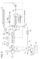
- FIG.4 is an illustration of a configuration of a hydraulic transmission.
- the wind turbine generator 1 is mainly provided with a rotor 2 rotating upon receiving wind, a hydraulic transmission 4 for increasing a rotation speed of the rotor 2, a generator 6 for generating electric power, and a control unit 30 for controlling a variety of components in the wind turbine generator 1.
- the control unit 30 functions as a "rotor-stop control unit” upon receiving a rotor stop command and controls each part of the wind turbine generator 1 (a pitch drive system 40, a hydraulic pump 20, a hydraulic motor 22 and an accumulator valve 62 all of which are described later) so as to stop the rotor 2.
- the control unit 30 includes a pitch controller 32 for controlling the pitch drive system 40, a pump controller 34 for controlling the hydraulic pump 20, a motor controller 36 for controlling the hydraulic motor 22, and an ACC valve controller 38 for controlling opening and closing of an accumulator valve 62 (62A, 62B).
- the pitch controller 32, the pump controller 34, the motor controller 36 and the ACC valve controller 38 are described later in details.
- the rotor 2 is formed by a blade 2A, a hub 2B to which the blade 2A is mounted, and a main shaft 2C connected to the hub 2B. With this configuration, the entire rotor 2 is rotated by a force of the wind received by the blade 2A and the rotation is inputted from the main shaft 2C to the hydraulic transmission 4.
- the angular position (rotational displacement) of the rotor 2 is measured by an angular position detector 29 attached to the main shaft 2C and then used for control performed by the control unit 30.
- the angular position detector 29 may be, for instance, a rotary encoder or a resolver.
- the main shaft 2C of the rotor 2 is housed in a nacelle 8 rotatably supported by a tower 7.
- the nacelle 8 supports the main shaft 2C via a main shaft bearing 3.
- the pitch drive system 40 illustrated in FIG.2 is housed in the hub 2B.
- the pitch drive system 40 is formed by a hydraulic cylinder 42, a servo valve 44, a pressurized-oil source 46 and an accumulator 48.
- the servo valve 44 adjusts, under control of the pitch controller 32, a supply amount of high pressure oil so as to achieve a desired pitch angle of the blade 4.
- the high pressure oil whose supply amount is controlled includes the high pressure oil generated by the pressurized-oil source 46 and the high pressure oil reserved in the accumulator 48.
- the pitch drive system 40 equipped with the hydraulic cylinder 42 is illustrated in FIG.2 .
- the pitch drive system 40 may use an actuator of any structure instead of the hydraulic cylinder 42 to adjust the pitch angle of the blade 2A by rotating the blade 2A around its axial center.
- an electric motor a servomotor
- it may be configured that the control signal from the pitch controller 32 is inputted to the electric motor and under control of the pitch controller 32, the electric motor adjusts the pitch angle of the blade 2A.
- the rotor 2 is configured to be locked by the locking pin 9 illustrated in FIG.1 .
- the locking pin 9 is inserted in each of the holes formed on the rotor side and on the nacelle side to lock the rotor 2.
- the configuration of the locking pin 9 and the holes where the locking pin is inserted are not particularly limited as long as the rotor 2 can be locked.
- the locking pin 9 and the holes may be configured as illustrated in FIG.3A to FIG.3C .
- the hub 2B and the main shaft 2C are integrally fastened together by a plurality of fastening members 5 and then fixed to an inner ring of the main shaft bearing 3. Further, a first hole 10 (see FIG.3C ) is formed in the hub 2B.
- the nacelle 8 is fixed to an outer ring of the main shaft bearing 3 at its end. As illustrated in FIG.3B , the end of the nacelle 8 partially projects inward (inward toward an axial center of the main shaft 2C) to form a projection 8A. In the projection 8A, a second hole 11 (see FIG.3C ) is formed.
- the locking pin 9 is insertable into the first hole 10 formed in the hub 2B and the second hole 11 formed in the projection 8A of the nacelle 8. Further, as illustrated in FIG.3C , a cylindrical member 12 is provided around the second hole 11. The cylindrical member 12 is fixed to the projection 8A. A male screw of a screw member 13 penetrating the cylindrical member 12 is screwed with a female screw formed in the cylindrical member 12. An end of the screw member 13 is screwed into a rear end of the locking pin 9. As a result, by rotating the screw member 13, the locking pin 9 can be freely forward and backward.
- a corner portion 14 of the end face of the locking pin 9 and a corner portion 15 of an opening end surface of the first hole 10 of the hub 2B are chamfered so that the locking pin 9 can be inserted smoothly.
- the corner portions 14, 15 may be chamfered into an inclined surface of approximately 45°C by cutting off corners, or may be round-chamfered by rounding the corners.
- FIG.3C illustrates the case where the corner portion 15 of the opening end surface of the first hole 10 is chamfered.
- this is not limitative and a corner portion of an opening end surface of the projection 8A of the nacelle 8 may be chamfered as well, which is an opposite side in a direction of inserting the locking pin 9 (the opening end surface on the right hand side in FIG.3C ).
- the hydraulic transmission. 4 illustrated in FIG.1 and FIG.4 is provided with the hydraulic pump 20 of a variable displacement type driven by rotation of the main shaft 2C, a hydraulic motor 22 of a variable displacement type connected to the generator 6, a high pressure oil line 24 and a low pressure oil line 26 arranged between the hydraulic pump 20 and the hydraulic motor 22.
- An outlet port of the hydraulic pump 20 is connected to an inlet port of the hydraulic motor 22 by the high pressure oil line 24.
- An inlet port of the hydraulic pump 20 is connected to an outlet port of the hydraulic motor 22 by the low pressure oil line 26.
- the operating oil (high pressure oil) discharged from the hydraulic pump 20 enters the hydraulic motor 22 via the high pressure oil line 24 to drive the hydraulic motor 22.
- the operating oil (low pressure oil) having performed the work in the hydraulic motor 22 then enters the hydraulic pump 20 via the low pressure oil line 26.
- the operating oil is pressurized in the hydraulic pump 20 and then enters the hydraulic motor 22 again via the high pressure oil line 24.
- the generator 6 connected to the hydraulic motor 22 is a synchronous generator connected to the grid 27 via a circuit breaker 25.
- the motor controller 36 adjusts the displacement of the hydraulic motor 22 so as to constantly maintain such a state that a generator shaft rotates at a synchronous speed based on a grid frequency of the grid 27 while the generator 6 is connected to the grid 27.
- an accumulator 60 (60A, 60B) is connected via the accumulator valve 62 (62A, 62B).
- the accumulator 60 may be a piston-type accumulator or a bladder-type accumulator having gas and the operating oil separated by a deformable bag (a bladder).
- a deformable bag a bladder
- the high pressure operating oil enters the accumulator 60 and the bladder is deformed or the piston is pushed, thereby compressing the gas.
- the compressed gas expands or high pressure gas is additionally introduced to deform the bladder or push the piston, thereby pushing the operating oil out from the accumulator 60.
- the opening and closing of the accumulator valve 62 is controlled by the ACC valve controller 38.
- FIG.4 illustrates the case where the accumulator 60 is connected to the high pressure oil line 24 via the accumulator valve 62. However, this is not limitative and the accumulator 60 may be directly connected to the high pressure oil line 24 without the accumulator valve 62. In this case, there is no control performed by the ACC valve controller 38.
- a pressure sensor 28 for measuring the pressure of the operating oil in the high pressure oil line 24 and an accumulator 64 for preventing pulsation (pressure fluctuation of the operating oil) are provided.
- an oil filter 66 for removing impurities contained in the operating oil and an oil cooler 68 for cooling the operating oil are provided in the low pressure oil line 26. Further, an oil tank 80 is connected to the low pressure oil line 26 via a replenishing line 82 and a return line 88.
- the oil tank 80 reserves the operating oil for replenishment.
- the operating oil reserved in the oil tank 80 is pumped by a boost pump 84 provided in the replenishing line 82 and supplied to the low pressure oil line 26.
- the operating oil passes through the oil filter 86 provided in the replenishing line 82 to remove impurities and then supplied to the low pressure oil line 26.
- a bypass flow path 70 is provided between the high pressure oil line 24 and the low pressure oil line 26 to bypass the hydraulic motor 22.
- a relief valve 72 is provided to maintain the pressure of the operating oil in the high pressure oil line 24 at or below a setting pressure of the relief valve 72.
- the relief valve 72 automatically opens to release the high pressure oil to the low pressure oil line 26 via the bypass flow path 70.
- the hydraulic pump 20 and the hydraulic motor 22 are variable-displacement pump and motor configured so that their displacements are adjustable.
- the displacement of the hydraulic pump 20 and the hydraulic motor 22 are controlled by the pump controller 34 and the motor controller 36 respectively.
- FIG.5 is an illustration of a configuration of the hydraulic pump 20.
- the hydraulic pump 20 is formed by: a plurality of hydraulic chambers formed by a plurality of cylinders 50 and a plurality of pistons 52, respectively; a cam having a cam profile engaging with the pistons 52; and a high pressure valve 56 and a low pressure valve 58 that are provided for each of the hydraulic chambers 53.
- the piston 52 may be formed by a piston body 52A slidable in the cylinder 50 and a piston roller or a piston shoe which is attached to the piston body 52A and engageable with the cam profile of the cam 54.
- FIG.5 illustrates the case where the piston 52 is formed by the piston body 52A and the piston roller 52B.
- the cam 54 is attached to an outer periphery of the main shaft 2C via a cam mount 55. While the main shaft 2C makes one rotation, the cam 54 moves each of the pistons 52 up and down a number of times to obtain large torque.
- a ring cam is configured to have wave-shaped lobes with depressions 54A and projections 54B alternately formed around the main shaft 2C. Further, the shape of the ring cam 54 may be determined so that the first hole 10 on the rotor 2 side matches the second hole 11 on the nacelle 8 side when at least one of the pistons 52 is at a root of the lobes of the ring cam 54 (the deepest point of the depression 54A).
- FIG.5 illustrates the case where a middle one of the three pistons 52 is at the root of the lobes of the ring cam 54.
- the high pressure valve 56 is arranged in a high pressure communication path 57 between the high pressure oil line 54 and each of the hydraulic chambers 53, whereas the low pressure valve 58 is arranged in a low pressure communication path 59 between the low pressure oil line 26 and each of the hydraulic chambers 53. Timing for opening and closing the high pressure valve 56 and the low pressure valve 58 is controlled by the pump controller 34.
- the pump controller 34 is configured to adjust displacement D P of the hydraulic pump 20 by changing a ratio of active chambers to the entire hydraulic chambers 53.
- the active chambers indicate the hydraulic chambers contributing to raising the pressure of the operating oil.
- the pump controller 34 controls the high pressure valve 56 to open and the low pressure valve 58 to close in a pump stroke in which the piston 52 moves from a bottom dead center toward a top dead center. Further, the pump controller 34 controls the high pressure valve 56 to close and the low pressure valve 58 to open in an intake stroke in which the piston 52 moves from the top dead center toward the bottom dead center.
- the high pressure oil is discharged from the active chamber to the high pressure oil line 24 via the high pressure valve 56 in the pump stroke and the low pressure oil is supplied to the active chamber from the low pressure oil line 26 via the low pressure valve 58 in the intake stroke.
- the pump controller 34 controls so as to maintain the high pressure valve 56 closed and the low pressure valve 58 open in cycles in which the piston 52 moves from the bottom dead center to the top dead center and returns to the bottom dead center.
- the high pressure oil is not discharged from the non-active chambers to the high pressure oil line 24 and thus the non-active chambers do not contribute to pressurizing of the operating oil.
- each of the high pressure valve 56 and the low pressure valve 58 is controlled.
- a check valve may be used as the high pressure valve 56 so as to allow only a flow of the operating oil toward the high pressure oil line 24.
- the high pressure valve 56 opens automatically.
- it is not necessary to actively control the high pressure valve 56.
- a position of the first hole 10 is matched with a position of the second hole 11.
- the hydraulic pump 20 is controlled by the pump controller 34 and a braking force is applied by at least the hydraulic pump 20 to the rotor 2 to stop the rotor 2 at a target angular position.
- target angular position herein means an angular position of the rotor at which the first hole 10 matches the second hole 11.
- FIG.6 is a flow chart depicting a process of controlling the hydraulic pump 20 by the pump controller 34 when stopping the rotor 2.
- a rotor stop command is received by the control unit 30 (step S1).
- the rotor stop command may be directly inputted from an input terminal of a control device of the wind turbine generator 1, or may be inputted from a remote site using wireless communication or wire communication. For instance, when a helicopter for transporting an operator is trying to access the power generating apparatus of the renewable energy type, the rotor stop command may be sent to the control unit 30 by remote control from the helicopter. Alternatively, the rotor stop command may be sent to the control unit 30 by remotely operating from a farm control room of the wind farm to which the wind turbine generator 1 belongs.
- the pump controller 34 of the control unit 30 obtains a detection result of the angular position (rotational displacement) of the rotor 2 by the angular position detector 29 (step S2). Then, based on the detection result of the angular position of the rotor 2, a torque demand T P of the hydraulic pump 20 for stopping the rotor 2 at a desired angular position is calculated (step S4).
- I is an inertia moment of the rotor 2
- ⁇ is an angular position of the rotor 2
- t is time
- T aero is a torque inputted to the rotor 2 from the wind
- T P is a torque demand of the hydraulic pump 20.
- the pump controller 34 adjusts the number of active chambers of the hydraulic pump 20 in accordance to a formula (3) below so as to achieve the displacement D P of the hydraulic pump 20 (step S10).
- D P m ⁇ Vp ⁇ Fdp
- m is the number of lobes of the cam 54
- Vp is net displacement of all the cylinders 50
- Fdp is a ratio of the active chambers to all the hydraulic chambers 53.
- step S12 determines whether or not the rotor 2 is stopped.
- the state of the rotor 2 may be determined based on the detection result of the angular position of the rotor 2 detected by the angular position detector 29. If the rotor 2 is not stopped (NO in the step S12), the process returns to the step S2 to control the hydraulic pump 20 again. On the other hand, if the rotor 2 is stopped (YES in the step S12), the process advances to a locking operation of the rotor 2 using the locking pin 9.
- the rotor 2 may be temporarily locked by maintaining such a state the high pressure valve 56 and the low pressure valve 58 of the hydraulic pump 20 are closed to keep the operating oil within the hydraulic chamber 53, thereby immobilizing the piston 52 (in a hydraulic locked state).
- the locking pin 9 can be efficiently inserted in the first hole 10 and the second hole 11.
- the accumulator valve 62 (62A, 62B) is opened by the ACC valve controller 38 to feed the excess operating oil from the high pressure oil line 24 to the accumulator 60 (60A, 60B) and then, the accumulator valve 62 (62A, 62B) is closed to reserve the excess operating oil in the accumulator 60 (60A, 60B).
- the operating oil having been reserved in the accumulator 60 may be released later when needed by opening the accumulator valve 62 (62A, 62B) by means of the ACC valve controller 38. For instance, the excess operating oil may be released from the accumulator 60 (60A, 60B) to assist rotation of the hydraulic motor 22.
- the excess operating oil can be reserved in the accumulator 60 (60A, 60B) without particular control. Furthermore, for a while after stopping or decelerating of the rotor 2, the operating oil reserved in the accumulator 60 may be released gradually so as to keep the hydraulic motor 22 operated to generate power.
- ⁇ D M Q EXCESS / n G
- Q EXCESS is the excess amount of the operating oil and n G is the rotation speed of the generator 6 (i.e. the rotation speed of the hydraulic motor 22). In this case, for an amount corresponding to the increased amount of the displacement ⁇ D M , more electric power is generated in the generator 6
- the excess operating oil generated by the increased displacement D P of the hydraulic pump 20 may be released to the low pressure oil line 26 via the bypass flow path 70 by opening the relief valve 72.
- the hydraulic motor 22 may be put into an idle state.
- the mechanical input from the hydraulic motor 22 to the generator 6 becomes zero and thus the balance between the mechanical input from the hydraulic motor 22 to the generator 6 and the electrical output of the generator 6 is maintained while the generator 6 is disconnected from the grid.
- the "idle state” herein indicates a state in which the displacement of the hydraulic motor 22 is zero.
- the rotor 2 is stopped by changing the torque of the hydraulic pump 20 and applying the braking force by at least the hydraulic pump 20 to the rotor 2, the rotor 2 is locked using the locking pin 9 so that the rotor 2 becomes immovable in the rotation direction.
- the braking force by the hydraulic pump 20 is finely adjustable by adjusting the displacement D P of the hydraulic pump 20 or the pressure P H in the high pressure oil line 24 and thus the rotor 2 can be stopped at any angular position. Further, by adjusting the torque T P of the hydraulic pump 20 as needed, it is possible to apply relatively large braking force to the rotor 2 so as to stop the rotor 2 promptly. In the case of applying the braking force by the brake system to the rotor 2, the rotational energy of the rotor 2 disperses as friction heat.
- the rotational energy of the rotor 2 is used to pressurize the operating oil. Further, the high pressure oil (the pressurized operating oil) from the hydraulic pump 20 can be used to increase electric power generated in the generator 6 if needed. As a result, the rotational energy can be utilized when stopping the rotor 2.
- the torque demand T P of the hydraulic pump 20 for stopping the rotor 2 at the target angular position is calculated based on the detection result of the angular position of the rotor 2 and the hydraulic pump 20 is controlled to achieve the displacement D P determined based on the calculated torque demand T P . More specifically, the displacement D P of the hydraulic pump 20 is adjusted based on the detection result obtained by the angular position detector 28 so as to stop the rotor 2 at the target angular position where the first hole 10 formed on the rotor 2 side matches the second hole 11 formed on the nacelle 8 side. In this manner, the rotor 2 can be automatically stopped at the target angular position by adjusting the braking force applied by the hydraulic pump 20. As a result, the locking operation of the rotor 2 can be performed efficiently.
- the torque (the braking force) of the hydraulic pump 20 is applied to the rotor 2 to stop the rotor 2.
- an aerobraking force may be applied to the rotor 2 in addition to the braking force by the hydraulic pump 20.
- the aerobraking force is generated by changing the pitch angle of the blade 2A to the feathering position by means of the pitch drive system 40 under control of the pitch controller 32.
- both the braking force by the hydraulic pump 20 and the aerobraking force through the pitch control are used at least in a part of the process of decelerating and stopping the rotor 2 (the process from receiving the rotor stop command for stopping the rotor 2), and it is not necessary to use both the braking force by the hydraulic pump 20 and the aerobraking force through the pitch control in the entire period of the process of decelerating and stopping the rotor.
- only one of the braking force by the hydraulic pump 20 and the aerobraking force through the pitch control may be used for a certain part of the process of decelerating and stopping the rotor 2 and both of the forces may be used for the rest of the process.
- the torque of the hydraulic pump 20 is adjusted to the torque demand T P according to the rotation speed of the rotor 2 and also the pitch angle of the blade 2A is changed to the feathering position so as to apply the aerobraking force to the rotor 2 in addition to the braking force by the hydraulic pump 20.
- the torque T P corresponding to the rotation speed of the rotor 2 may be obtained by inputting a measured rotation speed ⁇ of the rotor 2 in a known T P - ⁇ curve representing a relationship between the rotation speed ⁇ of the rotor 2 and the torque T P .
- the "target angular position” is an angular position of the rotor 2 at which the first hole 10 matches the second hole 11.
- this is not limitative and the “target angular position” may be any desired angular position for stopping the rotor 2.
- the rotor 2 is preferably stopped at the angular position where three blades 2A of the rotor 2 forms Y-shape to achieve easier access of the helicopter to the wind turbine generator 1.
- the "target angular position" is an angular position at which the three blades 2A of the rotor 2 form Y-shape.
- the "target angular position" is an angular position at which the intended blade 2A is positioned along a certain direction (e.g. approximately horizontal or vertical).
- the "target angular position" is an angular position appropriate for investigating the impact on said another wind turbine generator right behind the wind turbine generator 1.
- a wind turbine generator according to a second embodiment is described.
- the wind turbine generator of the second embodiment is similar to the wind turbine generator 1. of the first embodiment except that an additional valve is provided to cause the hydraulic pump 20 to perform a motoring operation.
- Configurations different from the above-described wind turbine generator 1 is mainly discussed and the same reference numerals are given without adding explanations for those configurations that are the same as the wind turbine generator 1.
- FIG.7 is an illustration of configurations of the hydraulic pump 20 having an additional valve for motoring operation.
- the hydraulic pump 20 is configured such that the cylinders 50, the pistons 52, the hydraulic chamber 52, the high pressure valve 56 and the low pressure valve 58 are housed in a casing 90.
- the high pressure valve 56 is, however, not shown in FIG.7 .
- the casing 90 is constituted by: an end plate 90A forming an end face of the hydraulic pump 20 on a side nearer to the hub 2B; an end plate 90B forming an end face of the hydraulic pump 20 on a side farther from the hub 2B; and a cylindrical wall 90C arranged between the end plates (90A, 90B).
- the hydraulic pump 20 illustrated in FIG. 7 is provided with multiple rows of the ring cams 54 (three arrays) in a longitudinal direction of the main shaft 2C, and corresponding pistons 52 and hydraulic chambers 53.
- the end plate 90 on the side farther from the hub 2B is formed with a through-hole 91.
- the through-hole 91 constitutes a part of a supply path 92 for supplying the pressurized oil from an external pressurized oil source to the hydraulic pump 20 (i.e. the hydraulic chamber 53).
- the pressurized oil is supplied from the supply path 92 to the hydraulic chamber 53 corresponding to the ring cam (a rear-most ring cam) disposed farthest from the hub 2B among the multiple rows of the ring cams 54.
- the pressurized oil is supplied to the hydraulic chamber 53 (the first working chamber from the right in FIG.7 ) corresponding to the rear-most ring cam 53 from the supply path 92 including the through hole 91 formed in the end plate 90 on the side farther from the hub 2B.
- the hydraulic pump 20 is disposed at the farther end of the main shaft 2C from the hub 2B and it is easy to form the supply path 92 by utilizing a peripheral space of the end plate 90B.
- a solenoid valve 93 of a normally-closed type, and a check valve 94 for allowing only the flow of the pressurized oil flowing toward the hydraulic chamber 53 from the pressurized oil source are provided.
- the solenoid valve 93 By exciting and opening the solenoid valve 93, the pressurized oil from the pressurized oil source flows through the check valve 94 and the through-hole 91 to the hydraulic chamber 53 in this order.
- the pressurized oil pushes down the piston 52 to rotate the ring cam 54 and then is discharged to the low pressure oil line 26 via the low pressure valve 58 and the low pressure communication path 59.
- the solenoid valve 93 and the check valve 94 may be attached to an outer surface of the end plate 90B on the side farther from the hub 2B.
- the opening and closing of the solenoid valve 93 is controlled by a valve controller 39 and the opening and closing of the low pressure valve 58 is controlled by the pump controller 34 (see FIG.9 ).
- the timings of opening and closing the solenoid valve 93 and the low pressure valve 58 are controlled in a synchronized timing with the reciprocating motion cycle of the piston 52.
- FIG.8 is a chart illustrating the opening/closing timings of the solenoid valve 93 and the low pressure valve 58.
- the solenoid valve 93 is open and the low pressure valve 58 is closed while the piston 52 moves from the top dead center (TDC) to the bottom dead center (BDC).
- TDC top dead center
- BDC bottom dead center
- the pressurized oil used for causing the hydraulic pump 20 to carry out the motoring operation may be the operating oil circulating in the hydraulic transmission 4.
- the pressurized oil supplied to the hydraulic chamber 53 during the motoring operation is the operating oil circulating in the hydraulic transmission 4, this has no adverse affect on the hydraulic transmission 4.
- FIG.9 is an illustration of a hydraulic circuit for causing the hydraulic pump 20 to carry out the motoring operation using the operating oil circulating in the hydraulic transmission 4.
- the supply path 92 is arranged between the oil tank 80 storing the low pressure oil and the hydraulic chambers 53 l and 53 k .
- the pump 95 is provided as the "pressurized oil source".
- the operating oil pumped by the pump 85 from the oil tank 80 is supplied as the "pressurized oil” to the hydraulic chambers 53 l and 53 k via the solenoid valve 93 and the check valve 94.
- FIG.9 depicts the case where in addition to the boost pump 84 for pumping up the operating oil from the oil tank 80 and supplying the operating oil to the low pressure oil line 26 via the replenishment line 82, the pump 95 is provided as the "pressurized oil source".
- the boost pump 84 may also function as the "pressurized oil source"
- the hydraulic pump 20 is typically designed such that a plurality of the pistons 52 reciprocates in different cycles. Further, the hydraulic pump 20 is usually designed with more than one group of at least two pistons 52 having the same phase in the reciprocating motion cycle in order to prevent the pulsation and to maintain the precise control of the displacement. In this manner, even if one of the pistons 52 fails, other pistons 52 belonging to the same group as the failed piston 52 can continue operating.
- the shape of the ring cam 54 is determined so that the piston 52 l reciprocates with the same phase as the piston 52 k disposed on an opposite side of the ring cam 54 from the piston 52 I .
- the shape of the ring cam 54 is determined so that the piston 52 i reciprocates with the same phase as the piston 52 i+k-1 disposed on an opposite side of the ring cam 54 from the piston 52 i . Therefore, with two pistons 52 i and 52 i+k-1 having the same phase of the reciprocating motion cycle, a redundancy is two.
- the solenoid valve 93 and the check valve 94 are shared by the two pistons 52 l and 52 i+k-1 belonging to the same group.
- FIG.9 illustrates the case where the solenoid valve 93 and the check valve 94 are shared by the pistons 52 l , 52 k belonging to the same group.
- the opening/closing of the solenoid valve 93 is controlled so as to achieve the motoring operation of the hydraulic pump 20.
- FIG.9 only shows the supply path 92 arranged between the hydraulic chambers 53 l and 53 k , but in reality, the supply path 92 is connected to the rest of the hydraulic chambers 53 as well.
- the rotor 2 is stopped at the target angular position using the braking force by at least the hydraulic pump 20.
- the target angular position herein is the angular position where the first hole 10 matches the second hole 11.
- the hydraulic pump 20 after stopping the rotor 2 by applying the braking force by at least the hydraulic pump 20, the hydraulic pump 20 is driven by the pressurized oil from the pressurized oil source (the pump 95) to rotate the rotor 2 to the target angular position.
- Fig. 10 is a flow chart depicting the process of stopping the rotor 2 at the target angular position.
- the steps S2 through S12 are the same as those explained in the first embodiment in reference to FIG.6 and thus, are not further explained.
- a detection result of the angular position (rotation displacement) of the rotor 2 is obtained by the angular position detector 29 (step S14). Then, based on the detection result obtained by the angular position detector 29, it is determined whether or not the first hole 10 on the rotor side matches the second hole 11 on the nacelle side, i.e. whether or not the rotor 2 is stopped at the target angular position (step S16).
- the process moves to the insertion of the locking pin 9 without performing the driving operation of the hydraulic pump 20 by the pressurized oil.
- the locking pin 9 may be inserted.
- step S16 the process advances to step S18 to drive the hydraulic pump 20 by the pressurized oil supplied from the pressurized oil source (the pump 95) so as to rotate the rotor 2.
- the rotor 2 may be rotated to the target angular position by controlling the opening and closing of the solenoid valve 93 and the low pressure valve 58 based on the measured angular position of the rotor 2 measured by the angular position detector 29.
- a period of time for controlling the opening and closing of the solenoid valve 93 and the low pressure valve 58 in synchronization with the timing of FIG.8 may be determined based on the difference between the current angular position and the desired angular position of the rotor 2.
- the number of the solenoid valves 93 and the low pressure valves 58 whose opening and closing is controlled in the timing shown in FIG.8 in synchronization with movement of the ring cam 54, may be determined based on the difference between the current angular position and the desired angular position of the rotor 2.
- the pressurized oil is supplied to the hydraulic pump 20 to drive the hydraulic pump 20 so as to rotate the rotor 2 to the desired angular position.
- the locking of the rotor 2 can be performed efficiently.
- the opening and closing of the solenoid valve 93 and the low pressure valve 58 are controlled and thus, the rotating of the rotor 2 to the desired angular position can be automated by driving the hydraulic pump 20.
- the locking of the rotor 2 can be performed efficiently.
- the solenoid valve 93 is provided for causing the hydraulic pump 20 to carry out the motoring operation, in addition to the high pressure valve 56 housed in the casing 90. This is for the following reasons.
- the high pressure valve 56 and the low pressure valve 58 that are housed in the casing 90 are a check valve and an electromagnetic valve of a normally-open type, respectively.
- the check valve is used as the high pressure valve 56, resulting in reduced size of the high pressure valve 56.
- an electromagnetic valve of a normally-closed type is provided as the solenoid valve 93 in addition to the high pressure valve 58.
- the high pressure valve 56 is designed to open and close by a pressure difference between the hydraulic chamber 53 and the high pressure oil line 24.
- the opening and closing of the high pressure valve 56 can be controlled with a small amount of electromagnetic force.
- the high pressure valve 56 can not be opened or closed until using the pressure difference generated by the reciprocation of the pistons 52.
- the solenoid valve 93 in addition to the high pressure valve 58 even in the case where the high pressure valve 56 housed in the casing is the electromagnetic valve.
- the aerobraking force may be applied to the hydraulic pump 20 in addition to the braking force by the hydraulic pump 20 when stopping the rotor 2 (S1 to S12 of FIG.10 ).
- the "target angular position” is the angular position of the rotor 2 where the first hole 10 matches the second hole 11.
- the "target angular position” may be any desired angular position for stopping the rotor 2.
- a wind turbine generator according to a third embodiment is described.
- the wind turbine generator of this embodiment is similar to the wind turbine generator 1 of the first embodiment except that a brake system for locking the rotor 2 and a turning device for turning the rotor 2 are provided. Therefore, configurations different from the above-described wind turbine generator 1 is mainly discussed and the same reference numerals are given without adding explanations for those configurations that are the same as the wind turbine generator 1.
- FIG.11 is a cross-sectional view of a configuration inside the nacelle 8 of a wind turbine generator 100 according to the third embodiment.
- FIG. 12 is an illustration of a detailed configuration around a brake disk.
- FIG.13 is an oblique perspective view of the main shaft and the brake disk taken from the hub side.
- FIG. 14 is an illustration of a configuration of a geared motor.
- the rotor is locked 2 using the brake system described later, instead of or in addition to the locking pin 9 described in the first embodiment.
- the main shaft 2C includes a front part 110 disposed nearer to the hub 2B and a rear part 112 disposed farther from the hub 2B as shown in FIG.11 .
- a stepped portion 112 is provided between the front part 110 and the rear part 112 and the front part 110 has a larger diameter than the rear part 112.
- a pair of main shaft bearings 3 (3A, 3B) for rotatably supporting the main shaft 2C are provided. More specifically, the front main shaft bearing 3A rotatably supports the front part 110 of the main shaft 2C and the rear main shaft bearing 3B rotatably supports the rear part 112 of the main shaft 2C.
- the main shaft bearings 3 (3A, 3B) are housed in bearing housings 116, respectively. From a perspective of improving strength against bending load and the like of the rotor 2, the bearing housings 116 are connected to each other by a connection frame 117 and the nacelle 8.
- Each of the bearing housings 116 is supported by the nacelle 8.
- the nacelle 8 is formed by a nacelle baseplate 8A supported rotatably by the tower and a cover 8B for covering the nacelle baseplate 8A
- each of the bearing housings 116 may be supported by the nacelle baseplate 8A or supported by the nacelle cover 8B.
- the front part 110 of the main shaft 2C is configured so that a front end nearer to the hub 2B protrudes outward in the radial direction of the main shaft 2C to form a flange 111.
- the flange 111 of the front part 110 is fastened to the hub 2B by bolts 114.
- a brake disk 130 for locking the rotor 2 is fastened together with the flange 111 and the hub 2B.
- the brake disk 130 includes, as shown in FIG.11 and FIG.12 , a fastening-object part 131 fastened together with the hub 2B and the flange 111 by means of the bolts 114, a middle part 132 which bends and extends from the fastening-object part 131 toward the bearing housing 116 of the main shaft bearing 3A, and a disk part 133 provided at an end of the middle part 132.
- the fastening-object part 131 is formed into an annular shape extending in the radial direction of the main shaft 2C along the flange 111 of the main shaft 2C.
- the middle part 132 extends toward the bearing housing 116 of the main shaft bearing 3A while tapering outward in the radial direction of the main shaft 2C from a position where the flange 111 of the front part 110 and the hub 2B are fastened together (i.e. a position of the bolt 114).
- disk parts 133 (133A, 133B) are provided on the outer circumferential and inner circumferential sides, respectively.
- the outer disk part 133 on the outer circumferential side extends outwardly in the radial direction of the main shaft 2C.
- the inner disk part 133B on the inner circumferential side extends inward in the radial direction of the main shaft 2C.
- the middle part 132 is provided tapering outward in the radial direction of the main shaft 2C from the fastening position where the flange 111 of the main shaft 2C and the hub 2B are fastened together. This increases a lever ratio, thereby making it possible to apply a larger braking force to the rotor 2. More specifically, by providing the middle part 132 tapering outward in the radial direction, a position of the brake disk 133 to which a frictional force is applied by a brake caliper 134 described later is moved farther outward in the radial direction from a shaft center of the main shaft 2C. As a result, even with a small frictional force by the brake caliper 134, a large braking force is applied to the rotor 2.
- the middle part 132 extending toward the bearing housing 116 of the main shaft bearing 3A from the fastening position where the middle part 132 is fastened together with the hub 2B and the main shaft 2C, the position of the brake disk 133 to which the frictional force is applied by the brake caliper 134 is moved closer to the main shaft bearing 3A which is a supporting point of the main shaft bearing 2C. More specifically, this decreases the distance between the disk part and the main shaft bearing 3A in the axial direction of the main shaft 2C. As a result, even when the net force of the frictional forces of all of the brake calipers 134 has a radial component, it is possible to reduce a moment load acting on the main shaft 2C caused by the radial component of the net friction force.
- the brake caliper 134 (134A, 134B) is provided to straddle the disk part 133 (133A, 133B) as shown in FIG. 12, FIG. 13 .
- the brake disk caliper 134 includes; a plurality of outer calipers 134A provided in correspondence to the disk part 133A on the outer circumferential side of the brake disk 130; and a plurality of inner calipers 134B provided in correspondence to the disk part 133B on the inner circumferential side of the brake disk 130.
- the plurality of brake calipers 134 (the outer calipers 134A and the inner calipers 134B) are provided on each of the outer circumferential side and the inner circumferential side of the brake disk 130. Thus, sufficient braking force is applied to the rotor 2.
- Each of the brake calipers 134 (134A, 134B) is configured to press a brake pad 135 against the disk part 133 (133A, 133B) of the brake disk using a hydraulic pressure so as to apply the braking force to the rotor 2.
- the brake caliper 134 is directly or indirectly supported by the bearing housing 116 of the font main shaft bearing 3A or by the nacelle baseplate 8A.
- a turning disk 140 for turning is attached to the main shaft 2C.
- a gear 142 is formed on an outer periphery of the turning disk 140.
- This turning disk 140 is configured rotatable using a geared motor 160 shown in FIG.14 . By this, the rotor 2 having been temporarily stopped is rotated to the target angular position.
- the geared motor 160 includes an electric motor 162 and a reducer 164.
- the reducer 164 is formed by a first gear 165, a second gear 166 and a third gear 167.
- the first gear 165 of the reducer 164 is attached to an output shaft of the electric motor 162.
- the second gear 166 of the reducer 164 is attached to a rotation shaft 170 and meshes with the first gear 165.
- the third gear 167 of the reducer is attached to the rotation shaft 170 and meshes with a gear 142 of the turning disk 140.
- the torque outputted from the electric motor 162 is increased by the first gear 165, the second gear 166 and the third gear 167 and then inputted to the turning disk 140.
- the rotation shaft 170 and the second gear 166 and the third gear 167 that are attached to the rotation shaft are configured movable in a direction indicated by an arrow A in FIG.14 .
- the third gear 167 of the geared motor 160 can be disengaged from the gear 142 of the turning disk 140, the third gear 167 of the geared motor 160 can mesh with the gear 142 of the turning disk 140, and the like.
- the third gear 167 of the geared motor 160 meshes with the gear 142 of the turning disk 140 so as to transmit the torque of the electric motor 162 to the turning disk 140.
- the third gear 167 of the geared motor 160 is removed and disengaged from the gear 142 of the turning disk 140.
- the third gear 167 of the geared motor 160 may be disengaged from the gear 142 of the turning disk 140 in accordance with a command from remote location.
- more than one geared motor 160 may be provided for the turning disk 140. As a result, a large torque can be inputted to the turning disk 140.
- the rotor 2 is stopped by applying the braking force by at least the hydraulic pump 20. Then, the rotor 2 is locked using a brake system illustrated in FIG.11 through FIG. 13 .
- the hydraulic pump 20 is rotated to the target angular position using the geared motor 160 or the pitch drive system 40.
- FIG. 15 is a flow chart depicting the process of stopping the rotor 2 at the target angular position.
- the steps S1 through S12 are the same as those explained in the first embodiment in reference to FIG.6 and thus, are not further explained.
- step S20 a result of measuring the angular position (rotation displacement) of the rotor 2 is obtained by the angular position detector 29 (step S20). Then, based on the detection result by the angular position detector 29, it is determined whether or not the rotor 2 is stopped at the target angular position (step S22).
- the process advances to a locking operation of the rotor 2 by means of the brake caliper 134 and the brake disk 130 without performing a turning operation of the rotor 2 by means of the geared motor 160 or the pitch drive system 40.
- the locking operation of the rotor 2 may be performed using the brake caliper 134 and the brake disk 130.
- step S22 if it is determined that the rotor 2 is not stopped at the target angular position (determined as NO in the step S22), the process advances to step S24 to perform the turning operation of the rotor by means of the geared motor or the pitch drive system 40.
- the turning operation of the rotor 2 is performed by adjusting the pitch angle of the blade 2A by means of the pitch drive system 40.
- the turning operation of the rotor 2 is performed by means of the geared motor 160.
- the geared motor 160 is designed on the assumption of its use in a high wind speed area, the geared motor 160 needs to be large-scale to generate torque large enough to counteract a strong force of the wind. In view of this, when the wind speed exceeds the threshold value, the pitch control is used instead of the geared motor 160 and aerodynamic torque is applied to the rotor 2 to perform the turning operation. In this manner, it is possible to avoid size increase of the geared motor 160.
- the geared motor 160 is attached to the main shaft 2C disposed between the hub 2B and the hydraulic pump 20 and its size is increased to generate large torque.
- the process After performing the turning operation of the rotor 2 using the geared motor 160 or the pitch drive system 40 in the step S24, the process returns to the step S22 to perform the determination of the step S22.
- the turning operation of the rotor 2 is performed by means of the geared motor 160 or the pitch drive system 40.
- the rotor can be rotated to the target angular position.
- the rotor 2 is turned by the geared motor 160 or the pitch drive system 40.
- this is not limitative and the rotor 2 may be rotated using the hydraulic cylinder.
- the hydraulic cylinders may be attached to the brake disk 130 so as to perform the turning operation of the rotor 2 by means of the hydraulic cylinders.
- the hydraulic cylinder 150 may be attached to the brake disk 130 via a bracket 152.
- the hydraulic cylinder 150 is installed in a standing manner on the nacelle baseplate 8A.
- the hydraulic cylinder 150 is fixed to the nacelle baseplate at one end is attached to the brake disk 130 via the bracket 152 at the other end.
- the bracket 152 is fastened to the brake disk 130 using a plurality of attachment holes 154 formed over an entire circumference of the outer disk part 133A of the brake disk 130. Further, the bracket 152 is attached to the outer disk part 133A in an area where the outer calipers 134A are not provided.
- the hydraulic cylinder 150 is attached rotatably to the nacelle baseplate 8A at a connection part 151 and to the bracket 152 at a connection part 53.
- the hydraulic cylinder 150 is configured to rotate around these connection parts 151, 153 in accordance with a rotation amount of the brake disk 130.
- the brake disk 130 i.e. the outer disk part 133A
- the brake disk 130 has relatively large diameter and thus the rotor 2 can be easily rotated even when the load of the rotor 2 becomes unbalanced during a removing operation of the blade 2A or the like,
- a pair of the hydraulic cylinders 150 may be provided at both sides of the brake disk 130, respectively.
- the brake disk 130 is turned by moving the pair of the hydraulic cylinders 150 in directions opposite to each other. More specifically, one of the hydraulic cylinders 150 applies an upward pressing force in the vertical direction to the braking disk 130, whereas the other of the hydraulic cylinders 150 applies a downward pressing force in the vertical direction to the braking disk 130.
- the pressing forces by the hydraulic cylinders 150 cancel majority of the radial component each other. Therefore, it is possible to reduce the moment load on the main shaft 2C caused by the radial component of the main shaft 2C which is the net force of the pressing force by the hydraulic cylinders 150.
- the aerodynamic force may be applied to the rotor 2 in addition to the braking force by the hydraulic pump when stopping the rotor 2 (S1 to S12 of FIG.10 ).
- the direction of the nacelle 8 with respect to the predominant wind direction during emergency may be regulated to a predetermine range (e.g. 90 ⁇ 45 degrees).
- the wind turbine generator 1 is designed with a torque of the brake system (the brake disk 130 and the brake caliper 134) higher than a certain value so as to be able to maintain the rotor 2 in a stopped state even when a strong wind blows. More specifically, during an emergency such as when a rescue aircraft approaches the wind turbine generator 1 to rescue an operator in the wind turbine generator 1, it is required to maintain the rotor 2 in the stopped state even when a strong wind of significantly high instantaneous wind speed (e.g. 35 m/s) blows.
- a strong wind of significantly high instantaneous wind speed e.g. 35 m/s
- the brake system designed to handle such high instantaneous wind speed is inevitably large-scale, resulting in weight gain of the brake system.
- the rotor 2 is locked by inserting the locking pin 9 in the first hole 10 on the rotor 2 side and the second hole 11 on the nacelle 8 side and in the third embodiment, the rotor 2 is locked using the brake disk 130 and the brake caliper 134.
- this is not limitative and any locking means besides the above means may be used.
- the displacement of the hydraulic pump 20, D P is changed when stopping the rotor 2 using the braking force by the hydraulic pump 20 (see the step S8).
- the pressure of the operating oil in the high pressure oil line 24, P H is adjustable, for instance, by increasing or decreasing the discharge amount of the operating oil from the hydraulic pump 20, Q P with respect to an intake amount of the operating oil to the hydraulic motor 22, Q M .
- the locking pin 9 is manually inserted into the first hole 10 and the second hole 11.
- the inserting operation of the locking pin 9 may be automated.
- FIG.16 illustrated an automated insertion of the locking pin 9.
- an actuator 96 is attached to a rear end side of the locking pin 9.
- the actuator 96 is controlled by an actuator control unit 98.
- a determination unit 99 it is determined whether or not the first hole 10 on the rotor 2 side (the hub 2B in the case illustrated in FIG.16 ) matches the second hole 11 on the nacelle 8 side (the projection 8A of the nacelle 8 in the case illustrated in FIG.16 ) based on a detection result obtained by the angular position detector 29 (see FIG.1 , FIG.9 ). Then, a determination result obtained by the determination unit 9 is sent to the actuator control unit 98.
- the actuator control unit 98 actuates the actuator 96 to insert the locking pin 9 into the first hole 10 and the second hole 11.
- a hydraulic cylinder may be used as the actuator 96, for instance.
Landscapes
- Engineering & Computer Science (AREA)
- Life Sciences & Earth Sciences (AREA)
- Sustainable Development (AREA)
- Sustainable Energy (AREA)
- Chemical & Material Sciences (AREA)
- Combustion & Propulsion (AREA)
- Mechanical Engineering (AREA)
- General Engineering & Computer Science (AREA)
- Power Engineering (AREA)
- Wind Motors (AREA)
Abstract
Description
- The present invention relates to a power generating apparatus of renewable energy type for generating power by transmitting rotational energy of a rotor to a generator via a hydraulic pump and a hydraulic motor and also a rotor locking method. The power generating apparatus of renewable energy type generates power from renewable energy such as wind, tidal current, ocean current and river current and, for instance, includes a wind turbine generator, a tidal generator, an ocean current generator, a river current generator or the like.
- In recent years, from a perspective of preserving the environment, it is becoming popular to use a power generating apparatus of renewable energy type such as a wind turbine generator utilizing wind power and a renewable energy type turbine generator such as a tidal current generator utilizing tidal currents. In the power generating apparatus of the renewable energy type, motion energy of the wind, the tidal current, the ocean current or the river current is converted into the rotational energy of the rotor and the rotational energy of the rotor is converted into electric power by the generator.
- In the power generating apparatus of the renewable energy type, the rotor is locked in some cases for safety reasons during replacement of the blade or maintenance of device components. When a helicopter for transporting operators accesses the power generating apparatus of the renewable energy type, the rotor is locked.
- Normally in this case, in such a state that the rotor is stopped at a position where a first hole formed in the rotor matches a second hole formed in the nacelle, a locking pin is inserted in the first and second holes to immobilize the rotor in a rotational direction.
- In the power generating apparatus of the renewable energy type, the rotor is decelerated and stopped normally by reducing the renewable energy received by the rotor through adjustment of a pitch angle of the blade (a pitch control). Further, the angle of rotation is adjusted using an actuator such as a hydraulic cylinder and an electric motor.
- However, a change rate of the pitch angle using an existing pitch drive system is approximately 3 deg/sec to 5 deg/sec and not so excellent in responsiveness. Thus, it is difficult to stop the rotor at a desired angular position solely by the pitch control. This is due to the fact that the torque applied to the rotor from the renewable energy source is heavily influenced by change in a flow speed of the renewable energy and it is difficult to precisely adjust the position of the rotor solely by the patch control which has low responsiveness.
- There are techniques for decelerating or stopping the rotor using a braking force of a brake system.
- For instance, proposed in
Patent Literature 1 is to lock the rotor using the locking pin at the angular position after stopping the rotor at a desired position by applying a braking force by the brake system to the rotor. More specifically, according toPatent Literature 1, the brake system is formed by a brake disk and a brake shoe and the rotor is decelerated by the brake system. The angular position of the rotor is detected by a position sensor and once the rotor is at the desired angular position, the locking pin is inserted automatically. - Further, in
Patent Literature 2, the rotor is decelerated by the pitch control and then based on detected angular position of the rotor, the braking force is applied to the rotor by the brake disk so as to stop the rotor at the desired angular position. More specifically, after the rotor is decelerated by the pitch control, once the rotor reaches a target angular position set just before the desired angular position, the brake system is activated to stop the rotor at the desired angular position. The target angular position, herein, indicates a position just before the desired angular position to stop the rotor and the desired angular position is set by taking into account the time that takes for the rotor to stop after activation of the brake system. - In recent years, development of a power generating apparatus of a renewably energy type using a hydraulic transmission with a combination of a hydraulic pump and a hydraulic motor instead of a gearbox which was an obstacle for weight and cost reduction is being developed (
e.g. Patent Literature 3 and Patent Literature 4). -
- [PTL 1]
US 7397145 - [PTL 2]
US 2011/0187107 A - [PTL 3]
US 2010/0032959 A - [PTL 4]
US 2010/0040470 A - In the method disclosed in
Patent Literature 1, the rotor is stopped at the desired angular position using the brake system but it is difficult to precisely adjust intensity of the braking force applied to the rotor by the brake system and thus sometimes the rotor is stopped at a position off the desired angular position. - Similarly, in the method disclosed in
Patent Literature 2, the rotor is decelerated by the pitch control and then ultimately stopped at the desired angular position using the brake system. Thus, sometimes the rotor is stopped at a position off the desired angular position. - Further, unlike a power generating apparatus of a renewable energy type equipped with a gearbox, the power generating apparatus of the renewable energy type equipped with the hydraulic transmission (e.g. those apparatuses described in
Patent Literatures 3 and 4), there is a special reason that it is difficult to increase the braking force applied by the brake system. - More specifically, in the power generating apparatus of the renewable energy type equipped with the gearbox, the rotation of the rotor, a few to tens of revolutions per minute (rpm) is increased approximately a hundredfold by the gearbox and inputted to the generator. Thus, by arranging the brake system to the rotations shaft between the gearbox and the generator, approximately 1/100 of the braking force is needed compared to the case where the brake system is provided to the main shaft between the hub and the gearbox. In contrast, in the power generating apparatus of the renewable energy type equipped with the hydraulic transmission, the rotation shaft rotating at high speed (low torque) between the hydraulic motor and the generator is not connected to the main shaft between the hub and the hydraulic pump. Thus, the brake system is attached to the main shaft disposed between the hub and the hydraulic pump and thus it is difficult to increase the braking force applied by the brake system.
- Therefore, in the case of the power generating apparatus of the renewable energy type equipped with the hydraulic transmission, it takes long to stop the rotor using the brake system.
- Further, in the methods of
Patent Literature 1 andPatent Literature 2, the rotor is decelerated and stopped using the pitch control and the brake system and thus energy is not utilized. More specifically, in the case of decelerating and stopping the rotor using the pitch control, the energy the rotor receives from the renewable energy source decreases. Further, in the case of decelerating and stopping the rotor using the brake system, the rotational energy of the rotor is converted into frictional heat and disperses in the air. - In view of the above issues, it is an object of the present invention to provide a power generating apparatus of a renewable energy type which is capable of stopping the rotor at a desired angular position promptly and also capable of utilizing energy when stopping the rotor, as well as a rotor locking method.
- The present invention provides a rotor locking method for a power generating apparatus of a renewable energy type which comprises: a rotor including a hub to which a blade is mounted and a main shaft connected to the hub; a hydraulic pump configured to be driven by rotation of the rotor; a hydraulic motor configured to be driven by operating oil pressurized by the hydraulic pump; and a generator connected to the hydraulic motor. The method according to the present invention comprises steps of:
- stopping the rotor by applying a braking force by at least the hydraulic pump to the rotor; and
- after the step of stopping the rotor, locking the rotor so as to immobilize the rotor in a rotational direction,
- wherein, in the step of stopping the rotor, torque of the hydraulic pump is changed so as to adjust the braking force.
- In this rotor locking method, the torque of the hydraulic pump is changed so as to adjust the braking force applied to the rotor. Thus, it is possible to stop the rotor at any angular position promptly when needed. More specifically, unlike a braking force applied by a brake system, the braking force applied by the
hydraulic pump 20 is finely adjustable by adjusting the displacement of the hydraulic pump or the pressure in the high pressure oil line between the hydraulic pump and the hydraulic motor. Thus the rotor can be stopped at any angular position. Further, by adjusting the torque of the hydraulic pump as needed, it is possible to apply relatively large braking force to the rotor so as to stop the rotor promptly. - Furthermore, in the case of applying the braking force by the brake system to the rotor, the rotational energy of the rotor disperses as friction heat. On the other hand, in the above case of applying the braking force by the hydraulic pump to the rotor, the rotational energy of the rotor is used to pressurize the operating oil. Further, the high pressure oil (the pressurized operating oil) from the hydraulic pump can be used to enhance electric power generated in the generator if needed. As a result, the energy can be utilized when stopping the rotor.
- In the above rotor locking method, the power generating apparatus of the renewable energy type may further comprise an angular position detector for detecting an angular position of the rotor, and in the step of stopping the rotor, the torque of the hydraulic pump may be adjusted based on a detection result obtained by the angular position detector so as to stop the rotor at a target angular position.
- As a result, the rotor can be automatically stopped at the target angular position by appropriately adjusting the torque of the hydraulic pump. Thus, the locking operation of the rotor can be performed efficiently.
- In this case, the target angular position is a position where a first hole formed on a rotor side matches a second hole formed on a nacelle side for housing the main shaft, and in the step of locking the rotor, a locking pin may be inserted in the first hole on the rotor side and the second hole on the nacelle side.
- As a result, after stopping the rotor at the target angular position (the position where the first hole formed on the rotor side matches the second hole formed on the nacelle side), the rotor can be immobilized in the rotational direction by inserting the locking pin in the first hole and the second hole.
- In the above rotor locking method, a brake pad may be pressed against a brake disk attached to the rotor in the step of locking the rotor.
- As a result, after stopping the rotor at an arbitrary angular position by changing the torque of the hydraulic pump, the rotor can be immobilized in the rotational direction using the brake disk and the brake pad.
- The above rotor locking method may further comprise a step of rotating the rotor to a target angular position after the step of stopping the rotor and before the step of locking the rotor.
- For instance, when a torque applied to the rotor from a renewable energy source is affected by flow speed change of the renewable energy and suddenly changes, it is difficult to stop the rotor at a desired angular position by adjusting the torque of the hydraulic pump. Moreover, after stopping the rotor at the desired angular position, the rotor may continue to move from some cause, causing misalignment from the target angular position afterward.
- In view of this, as described above, the rotor is stopped and then rotated to the target angular position to securely lock the rotor at this target angular position.
- In the case of temporarily stopping the rotor and then rotating the rotor to the target angular position, in the step of rotating the rotor, the hydraulic pump may be driven by pressurized oil supplied to the hydraulic pump so as to rotate the rotor to the target angular position.
- By driving the hydraulic pump by supplying the pressurized oil (i.e. by causing the hydraulic pump to perform motoring operation), the rotor is rotated to the target angular position and is stopped at this target angular position. Moreover, the hydraulic pump is needed in the first place to transmit the rotational energy of the rotor to the generator and thus by making the hydraulic pump to perform the motoring operation, it is not necessary to provide a device specifically for rotating the rotor to the target angular position.
- In the case of rotating the rotor to the target angular position by supplying the pressurized oil to the hydraulic pump, the power generating apparatus of the renewable energy type may further comprise an angular position detector for detecting an angular position of the rotor, and in the step of rotating the rotor, opening and closing of a valve provided in a supply path for supplying the pressurized oil to the hydraulic pump is controlled based on a detection result obtained by the angular position detector so as to rotate the rotor to the target angular position.
- As a result, the operation of stopping the rotor at the target angular position through the motoring operation of the hydraulic pump can be automated. Thus, the locking operation of the rotor can be efficiently performed.
- Alternatively, in the case of temporarily stopping the rotor and then rotating the rotor to the target angular position, in the step of rotating the rotor, in such a case that a wind speed is not less than a threshold value, the rotor is rotated to the target angular position by adjusting a pitch angle of the blade, and in such a case that the wind speed is less than the threshold value, the rotor is rotated to the target angular position by a geared motor.
- If the geared motor is designed on the assumption of its use in a high wind speed area, the geared motor needs to be large-scale to generate torque large enough to counteract a strong force of the wind. In view of this, when the wind speed exceeds the threshold value, the pitch control is used and when the wind speed is below the threshold value, the geared motor is used. As a result, it is possible to avoid size increase of the geared motor.
- Particularly, by using the hydraulic transmission similarly to the above power generating apparatus of the renewable energy type, it is inevitable that the geared motor is attached to the main shaft disposed between the hub and the hydraulic pump and its size is increased to generate large torque. In view of this, by using both the pitch drive system and the geared motor as described above, it is extremely beneficial to avoid size increase of the geared motor.
- Further, the geared motor indicates a motor with a reducer so as to increase the torque of the motor by the reducer and apply the increased torque to the rotor.
- In the above rotor locking method according to
claim 1, the power generating apparatus of the renewable energy type may further comprise a high pressure oil line for supplying the operating oil from the hydraulic pump to the hydraulic motor and a low pressure oil line for returning the operating oil from the hydraulic motor to the hydraulic pump. The hydraulic pump may comprise: a cylinder; a piston slidable in the cylinder in response to rotation of the rotor; a hydraulic chamber formed by the cylinder and the piston; a high pressure valve for opening and closing a communication path between the hydraulic chamber and the high pressure oil line; and a low pressure valve for opening and closing a communication path between the hydraulic chamber and the low pressure oil line. The rotor locking method further comprises a step of: after the step of stopping the rotor and before the step of locking the rotor, temporarily locking the rotor by maintaining such a state that the high pressure valve and the low pressure valve are closed. - By maintaining the state that the high pressure valve and the low pressure valve are closed, the operating oil is sealed in the hydraulic chamber, thereby immobilizing the piston (in a hydraulic locked state). As a result, the rotor is temporarily looked. Further, in the hydraulic locked state, the operating oil leaks to some extent, and it is difficult to completely immobilize the rotor. This is, however, extremely useful to temporarily lock the rotor before completely locking the rotor.
- In the above rotor locking method, in the step of stopping the rotor, the torque of the hydraulic pump may be adjusted to a torque demand value in accordance with a rotation speed of the rotor and a pitch angle of the blade is changed toward a feathering position so as to apply a force of aerobraking to the rotor in addition to the braking force applied by the hydraulic pump. In this case, both the braking force by the hydraulic pump and the aerobraking force through the pitch control are used at least in part the process of decelerating and stopping the rotor, and it is not necessary to use both the braking force by the hydraulic pump and the aerobraking force through the pitch control in the entire period of the process of decelerating and stopping the rotor.
- For instance, in the step of stopping the rotor, the torque of the hydraulic pump is adjusted to the torque demand TP according to the rotation speed of the rotor and also the pitch angle of the blade is changed to a feathering position so as to apply the aerobraking force to the rotor in addition to the braking force by the hydraulic pump.
- By using both the braking force by the hydraulic pump and the aerobraking force through the pitch control as described above, the rotor can be stopped promptly. Further, by using both the braking force by the hydraulic pump and the aerobraking force through the pitch control, even if one of them fails, the other is still available to securely stop the rotor.
- In the above rotor locking method, the power generating apparatus of the renewable energy type may further comprise a circuit breaker for changing a connection state between the generator and a grid, and the rotor locking method may further comprise steps of:
- when output of the generator becomes not greater than a threshold value upon stopping of the rotor, disconnecting the generator from the grid by opening the circuit breaker; and
- immediately before the step of disconnecting the generator, making the hydraulic motor into an idle state.
- In the case where the generator connected to the grid is connected to the hydraulic motor, once electric output of the generator declines to a certain level, the generator needs to be disconnected from the grid. The disconnection of the generator, however, instantaneously causes sudden drop of the electrical output to zero. As a result, the balance between the mechanical input from the hydraulic motor to the generator and the electrical output of the generator is maintained during disconnection of the
generator 6 from the grid. This causes imbalance between mechanical input from the electrical motor to the generator and the electrical output of the generator, resulting in acceleration of the generator shaft - In view of this, just before the step of disconnecting the generator from the grid, the hydraulic motor is put into an idle state. By operating the hydraulic motor in the idle state, the mechanical input from the hydraulic motor to the generator becomes zero and thus the balance between the mechanical input from the hydraulic motor to the generator and the electrical output of the generator is maintained during disconnection of the
generator 6 from the grid. As a result, it is possible to prevent acceleration of the generator shaft during disconnection of the generator. - In the above rotor locking method, the power generating apparatus of the renewable energy type may further comprise a high pressure oil line for supplying the operating oil from the hydraulic pump to the hydraulic motor, an accumulator may be connected to the high pressure oil line, and in the step of stopping the rotor, at least displacement of the hydraulic pump may be increased so as to reserve in the accumulator excess operating oil that is excess in the high pressure oil line.
- By increasing the displacement of the hydraulic pump to enhance the braking force (torque) by the hydraulic pump, the flow of the operating oil discharged to the high pressure oil line from the hydraulic pump increases. Thus, by reserving the excess operating oil in the accumulator, the excess operating oil (high pressure oil) can be absorbed in the accumulator.
- Moreover, the accumulator may be directly connected to the high pressure oil line, or may be connected to the high pressure oil line via a solenoid valve. In the case where the accumulator is directly connected to the high pressure oil line, the excess operating oil (the high pressure oil) can be reserved in the accumulator without any particular control. Then, for a while after decelerating or stopping the rotor, the operating oil (the high pressure oil) reserved in the accumulator is gradually released to drive the hydraulic motor, thereby continuing to generate power. In contrast, in the case where the accumulator is connected to the high pressure oil line via the solenoid valve, the excess operating oil is reserved in the accumulator by opening the solenoid valve when the rotor is stopped. Then, if needed later, the reserved operating oil is released to assist rotation of the hydraulic motor.
- In the above rotor locking method, the power generating apparatus of the renewable energy type may further comprise a high pressure oil line for supplying the operating oil from the hydraulic pump to the hydraulic motor, and in the step of stopping the rotor, at least displacement of the hydraulic pump may be increased, and displacement of the hydraulic motor may be temporarily increased so as to absorb excess operating oil in the high pressure oil line by means of the hydraulic motor.
- By temporarily increasing the displacement of the hydraulic motor, not only the excess operating oil in the high pressure oil line caused by the increased displacement of the hydraulic pump can be absorbed by the hydraulic motor but also electric power generated by the generator can be increased. As a result, the rotational energy of the rotor is not wasted.
- In the above rotor locking method, the power generating apparatus of the renewable energy type may further comprise a high pressure oil line for supplying the operating oil from the hydraulic pump to the hydraulic motor, a low pressure oil line for returning the operating oil from the hydraulic motor to the hydraulic pump, a bypass flow path connected to the high pressure oil line and the low pressure oil line for bypassing the hydraulic motor, and a relief valve provided in the bypass flow path, and in the step of stopping the rotor, at least displacement of the hydraulic pump may be increased so as to cause excess operating oil in the high pressure oil line to be released to the low pressure oil line via the bypass flow path and the relief valve.
- By using the bypass flow path and the relief valve, the excess operating oil resulting from the increased displacement of the hydraulic pump can be released to the low pressure oil line from the high pressure oil line.
- The above rotor locking method may further comprise a step of:
- supplying a rotor stop command to the power generating apparatus of the renewable energy type from a remote site, and
- the step of stopping the rotor may be performed automatically based on the rotor stop command.
- As a result, the rotor can be automatically stopped according to the rotor stop command from a remote site. Therefore, for instance, when a helicopter for transporting an operator accesses the power generating apparatus of the renewable energy type, the rotor stop command may be remotely sent from the helicopter to stop the rotor automatically. As a result, this facilitates the access by the helicopter.
- The above power generating apparatus of the renewable energy type may be a wind turbine generator configured such that the rotor is rotated by wind in a form of renewable energy, torque of the rotor is inputted to the generator via the hydraulic pump and the hydraulic motor and electric power is generated in the generator.
- A power generating apparatus of a renewable energy type according to the present invention may comprise:
- a rotor including a blade, a hub to which blade is mounted and a main shaft connected to the hub;
- a hydraulic pump configured to be driven by rotation of the rotor;
- a hydraulic motor configured to be driven by operating oil pressurized by the hydraulic pump;
- a generator connected to the hydraulic motor;
- a rotor-stop control unit for stopping the rotor by applying a braking force by at least the hydraulic pump to the rotor; and
- a locking device for locking the rotor so as to immobilize the rotor in a rotational direction, and
- the rotor-stop control unit may change torque of the hydraulic pump to change the braking force.
- In the above power generating apparatus of the renewable energy type, the rotor-stop control unit changes the torque of the hydraulic pump to change the braking force applied to the rotor and thus the rotor can be promptly stopped at any angular position when needed. More specifically, unlike a braking force applied by a brake system, the braking force applied by the
hydraulic pump 20 is finely adjustable by adjusting the displacement of the hydraulic pump or the pressure in the high pressure oil line between the hydraulic pump and the hydraulic motor. Thus the rotor can be stopped at any angular position. Further, by adjusting the torque of the hydraulic pump as needed, it is possible to apply relatively large braking force to the rotor so as to stop the rotor promptly. - Furthermore, in the case of applying the braking force by the brake system to the rotor, the rotational energy of the rotor disperses as friction heat. On the other hand, in the above case of applying the braking force by the hydraulic pump to the rotor, the rotational energy of the rotor is used to pressurize the operating oil. Thus, the high pressure oil (the pressurized operating oil) from the hydraulic pump can be used to enhance electric power generated in the generator if needed. As a result, the energy can be utilized when stopping the rotor.
- The above power generating apparatus of the renewable energy type may further comprise an angular position detector for detecting an angular position of the rotor. The rotor-stop control unit may be configured to adjust the torque of the hydraulic pump based on a detection result obtained by the angular position detector so as to stop the rotor at a target angular position.
- As a result, the rotor can be automatically stopped at the target angular position by appropriately adjusting the torque of the hydraulic pump. Thus, the locking operation of the rotor can be performed efficiently.
- The above power generating apparatus of the renewable energy type may further comprise:
- an angular position detector for detecting an angular position of the rotor;
- an oil source for supplying pressurized oil to the hydraulic pump;
- a valve provided in a supply path through which the pressurized oil is supplied to the hydraulic pump from the oil source; and
- a valve controller for controlling opening and closing of the valve based on a detection result obtained by the angular position detector so as to drive the hydraulic pump by the pressurized oil from the oil source and rotate the rotor to a target angular position.
- By driving the hydraulic pump by supplying the pressurized oil from the oil source (i.e. by causing the hydraulic pump to perform motoring operation), the rotor can be rotated to the target angular position and is stopped at this target angular position.
- In the case of rotating the rotor to the target angular position by driving the hydraulic pump using the pressurized oil from the oil source, the power generating apparatus of the renewable energy type may further comprise:
- a high pressure oil line for supplying the operating oil from the hydraulic pump to the hydraulic motor; and
- a low pressure oil line for returning the operating oil from the hydraulic motor to the hydraulic pump. And the hydraulic pump may comprise:
- a cylinder;
- a piston slidable in the cylinder in response to rotation of the rotor;
- a hydraulic chamber formed by the cylinder and the piston;
- a high pressure valve for opening and closing a communication path between the hydraulic chamber and the high pressure oil line;
- a low pressure valve for opening and closing a communication path between the hydraulic chamber and the low pressure oil line; and
- a casing for housing the cylinder, the piston, the hydraulic chamber, the high pressure valve and the low pressure valve. And the supply path may penetrate the casing from the oil source and communicates with the hydraulic chamber, and the valve may be a solenoid valve provided in the supply path for the pressurized oil.
- In the hydraulic pump having the piston, the hydraulic chamber, the high pressure valve, the low pressure valve and the casing for housing these components, compact high pressure valve and low pressure valve are used in some cases. These compact high pressure valves and low pressure valves are designed to open and close using a pressure difference between the hydraulic chamber and the high pressure oil line or the low pressure oil line or to assist the opening and closing. This type of high pressure valve and low pressure valve housed in the casing is not openable/closable until there is the pressure difference generated by the reciprocating motion of the piston in response to the rotation of the rotor. When driving the hydraulic pump by the pressurized oil from the oil source, the pressure difference is not available and thus the opening and closing of the high pressure valve and low pressure valve cannot be controlled. Therefore, by providing a valve for changing the supply state of the operating oil to the hydraulic pump separately from the high pressure valve and low pressure valve housed in the casing, the hydraulic pump can be positively driven by the pressurized oil from the oil source.
- The valve may be attached to the outside of the casing. The valve may be attached to an end face of the casing that is on a side farther from the hub.
- Further, in this case, the hydraulic pump further comprise a ring cam having wave-shaped lobes for determining a reciprocating motion cycle of the piston, and the hydraulic pump may have a plurality of groups each of which is formed by at least two of the pistons having the same phase of the reciprocating motion cycle, and the valve may be commonly provided for the at least two of the pistons belonging to each of the groups.
- For the purpose of preventing pulsation and precisely controlling the displacement, this type of hydraulic pump is typically designed such that a plurality of the pistons reciprocates in different cycles. Further, the hydraulic pump is usually designed with more than one group of at least two pistons that have the same phase of the reciprocating motion cycle in order to prevent the pulsation and to maintain the precise control of the displacement. In this manner, even if one of the pistons fails, other pistons belonging to the same group as the failed piston can continue operating.
- Therefore, by commonly providing the valve (a common valve) for n piston of the same group having the same phase of the reciprocating motion cycle (n being an integer not less than two), it is possible to drive the hydraulic pump using the pressurized oil from the oil source by opening and closing the common valve in synchronization with the movement of the ring cam. Thus, it is possible to perform the drive control of the hydraulic pump by the pressurized oil with fewer valves.
- Further, in the case where the phase of the reciprocating motion cycle of the n pistons is the same, the redundancy is n.
- In the above power generating apparatus of the renewable energy type, the locking device may be a locking pin insertable in a first hole formed on a rotor side and a second hole formed on a nacelle side for housing the main shaft, the hydraulic pump may comprise a plurality of cylinders, a plurality of pistons being slidable in the plurality of cylinders, respectively, and a ring cam provided on an outer circumference of the main shaft and having wave-shaped lobes for determining a reciprocating motion cycle of the plurality of pistons, and a shape of the ring cam may be determined so that the first hole matches the second hole when at least one of the pistons is at a root of the lobes of the ring cam.
- It is easier to maintain the rotor at the angular position where at least one of the pistons is at the root of the lobes of the ring cam than to maintain the rotor at an angular position where none of the piston is at the root of the lobes of the ring cam. Therefore, by determining the shape of the ring cam so that the first hole matches the second hole when at least one of the pistons is at a root of the lobes of the ring cam, the rotor can be easily kept at the angular position after stopping the rotor at the angular position where the first hole matches the second hole and until the locking pin is inserted. As a result, the locking operation of the rotor can be performed efficiently.
- In the above power generating apparatus of the renewable energy type, the locking device may be a locking pin insertable in a first hole formed on a rotor side and a second hole formed on a nacelle side for housing the main shaft, and the power generating apparatus of the renewable energy type may further comprise:
- an angular position detector for detecting an angular position of the rotor;
- an actuator attached to the locking pin;
- a determination unit for determining whether or not the first hole matches the second hole based on a detection result obtained by the angular position detector; and
- an actuator control unit for causing the actuator to insert the locking pin in the first hole and the second hole when it is determined that the first hole matches the second hole.
- As a result, the operation of inserting the locking pin into the first hole and the second hole using the actuator can be automated. Thus, the locking operation of the rotor can be performed efficiently.
- In the above power generating apparatus of the renewable energy type, the locking device may be a locking pin insertable in a first hole formed on a rotor side and a second hole formed on a nacelle side for housing the main shaft, and a tip surface of the locking pin and an opening end surface of at least one of the first hole or the second hole opposite to a direction of inserting the locking pin may be chamfered.
- By chamfering the tip surface of the locking pin and the opening end surface of at least one of the first hole or the second hole, the locking pin can be easily inserted into the first hole and the second hole. Thus, the locking operation of the rotor can be performed efficiently.
- According to the present invention, the torque of the hydraulic pump is changed so as to adjust the braking force applied to the rotor. Thus, it is possible to stop the rotor at any angular position promptly when needed. More specifically, unlike a braking force applied by a brake system, the braking force applied by the
hydraulic pump 20 is finely adjustable by adjusting the displacement of the hydraulic pump or the pressure in the high pressure oil line between the hydraulic pump and the hydraulic motor. Thus the rotor can be stopped at any angular position. Further, by adjusting the torque of the hydraulic pump as needed, it is possible to apply relatively large braking force to the rotor so as to stop the rotor promptly. - Further, in the case of applying the braking force by the brake system to the rotor, the rotational energy of the rotor disperses as friction heat. On the other hand, in the case of applying the braking force by the hydraulic pump to the rotor, the rotational energy of the rotor is used to pressurize the operating oil. Thus, the high pressure oil (the pressurized operating oil) from the hydraulic pump can be used to enhance electric power generated in the generator if needed. As a result, the energy can be utilized when stopping the rotor.
-
- [
FIG.1 ]
FIG.1 is an illustration of a configuration of a wind turbine generator according to a first embodiment. - [
FIG.2 ]
FIG.2 is an illustration of a configuration of a pitch drive system. - [
FIG.3A ]
FIG.3A is a cross-sectional view of a hub and a nacelle in a periphery of locking pins. - [
FIG.3B ]
FIG.3B is a view taken from arrow A ofFIG.3A . - [
FIG.3C ]
FIG.3C is a cross-sectional view taken along line B-B ofFIG.3B . - [
FIG.4 ]
FIG.4 is an illustration of a configuration of a hydraulic transmission. - [
FIG.5 ]
FIG.5 is an illustration of a configuration of the hydraulic pump. - [
FIG.6 ]
FIG.6 is a flow chart depicting a process of controlling the hydraulic pump by a pump controller when stopping a rotor. - [
FIG.7 ]
FIG.7 is an illustration of a configuration of the hydraulic pump additionally provided with a valve for motor operation. - [
FIG.8 ]
FIG.8 is a chart depicting a timing of opening and closing the valve for motor operation (a solenoid valve) and a low pressure valve. - [
FIG.9 ]
FIG.9 is an illustration of a hydraulic circuit for motor operation of the hydraulic pump with use of operating oil circulating in the hydraulic transmission. - [
FIG.10 ]
FIG.10 is a flow chart depicting a process until stopping the rotor at a target angular position. - [
FIG.11 ]
FIG.11 is a cross-sectional view of a configuration inside a nacelle of the wind turbine generator according to a third embodiment. - [
FIG.12 ]
FIG.12 is an illustration of a detailed configuration around a brake disk. - [
FIG.13 ]
FIG.13 is an oblique perspective view of a main shaft and the brake disk taken from a hub side. - [
FIG.14 ]
FIG.14 is an illustration of a configuration of a geared motor. - [
FIG. 15 ]
Fig. 15 is a flow chart depicting a process until stopping the rotor at the target angular position. - [
FIG. 16 ]
FIG.16 is an illustration of automatic insertion of the locking pin. - Embodiments of the present invention will now be described in detail with reference to the accompanying drawings. It is intended, however, that unless particularly specified, dimensions, materials, shape, its relative positions and the like shall be interpreted as illustrative only and not limitative of the scope of the present invention.
- While the present invention has been described with reference to exemplary embodiments, it is obvious to those skilled in the art that the first embodiment and the second embodiment may be freely combined and various changes may be made without departing from the scope of the invention.
- In the following embodiments, a wind turbine generator is described as an example of the power generating apparatus of the renewable energy type. However, this is not limitative and the present invention is also applicable to other types of power generating apparatuses of a renewable energy type such as a tidal generator, an ocean current generator and a river current generator.
-
FIG.1 is an illustration of a configuration of a wind turbine generator according to a first embodiment.FIG.2 is an illustration of a configuration of a pitch drive system.FIG.3A is a cross-sectional view of a hub and a nacelle in a periphery of locking pins.FIG.3B is a view taken from arrow A ofFIG.3A. FIG.3C is a cross-sectional view taken along line B-B ofFIG.3B .FIG.4 is an illustration of a configuration of a hydraulic transmission. - As shown in
FIG.1 , thewind turbine generator 1 is mainly provided with arotor 2 rotating upon receiving wind, ahydraulic transmission 4 for increasing a rotation speed of therotor 2, agenerator 6 for generating electric power, and acontrol unit 30 for controlling a variety of components in thewind turbine generator 1. - The
control unit 30 functions as a "rotor-stop control unit" upon receiving a rotor stop command and controls each part of the wind turbine generator 1 (apitch drive system 40, ahydraulic pump 20, ahydraulic motor 22 and an accumulator valve 62 all of which are described later) so as to stop therotor 2. Thecontrol unit 30 includes apitch controller 32 for controlling thepitch drive system 40, apump controller 34 for controlling thehydraulic pump 20, amotor controller 36 for controlling thehydraulic motor 22, and anACC valve controller 38 for controlling opening and closing of an accumulator valve 62 (62A, 62B). Thepitch controller 32, thepump controller 34, themotor controller 36 and theACC valve controller 38 are described later in details. - The
rotor 2 is formed by ablade 2A, ahub 2B to which theblade 2A is mounted, and amain shaft 2C connected to thehub 2B. With this configuration, theentire rotor 2 is rotated by a force of the wind received by theblade 2A and the rotation is inputted from themain shaft 2C to thehydraulic transmission 4. The angular position (rotational displacement) of therotor 2 is measured by anangular position detector 29 attached to themain shaft 2C and then used for control performed by thecontrol unit 30. Theangular position detector 29 may be, for instance, a rotary encoder or a resolver. - The
main shaft 2C of therotor 2 is housed in anacelle 8 rotatably supported by atower 7. Thenacelle 8 supports themain shaft 2C via amain shaft bearing 3. - The
pitch drive system 40 illustrated inFIG.2 is housed in thehub 2B. Thepitch drive system 40 is formed by ahydraulic cylinder 42, aservo valve 44, a pressurized-oil source 46 and anaccumulator 48. Theservo valve 44 adjusts, under control of thepitch controller 32, a supply amount of high pressure oil so as to achieve a desired pitch angle of theblade 4. The high pressure oil whose supply amount is controlled includes the high pressure oil generated by the pressurized-oil source 46 and the high pressure oil reserved in theaccumulator 48. - The
pitch drive system 40 equipped with thehydraulic cylinder 42 is illustrated inFIG.2 . Thepitch drive system 40 may use an actuator of any structure instead of thehydraulic cylinder 42 to adjust the pitch angle of theblade 2A by rotating theblade 2A around its axial center. For instance, an electric motor (a servomotor) may be used as an actuator to adjust the pitch angle. In this case, it may be configured that the control signal from thepitch controller 32 is inputted to the electric motor and under control of thepitch controller 32, the electric motor adjusts the pitch angle of theblade 2A. - The
rotor 2 is configured to be locked by the lockingpin 9 illustrated inFIG.1 . Thelocking pin 9 is inserted in each of the holes formed on the rotor side and on the nacelle side to lock therotor 2. The configuration of thelocking pin 9 and the holes where the locking pin is inserted are not particularly limited as long as therotor 2 can be locked. Thelocking pin 9 and the holes may be configured as illustrated inFIG.3A to FIG.3C . - In the case illustrated in
FIG.3A to FIG.3C , thehub 2B and themain shaft 2C are integrally fastened together by a plurality offastening members 5 and then fixed to an inner ring of themain shaft bearing 3. Further, a first hole 10 (seeFIG.3C ) is formed in thehub 2B. - The
nacelle 8 is fixed to an outer ring of the main shaft bearing 3 at its end. As illustrated inFIG.3B , the end of thenacelle 8 partially projects inward (inward toward an axial center of themain shaft 2C) to form aprojection 8A. In theprojection 8A, a second hole 11 (seeFIG.3C ) is formed. - The
locking pin 9 is insertable into thefirst hole 10 formed in thehub 2B and thesecond hole 11 formed in theprojection 8A of thenacelle 8. Further, as illustrated inFIG.3C , acylindrical member 12 is provided around thesecond hole 11. Thecylindrical member 12 is fixed to theprojection 8A. A male screw of ascrew member 13 penetrating thecylindrical member 12 is screwed with a female screw formed in thecylindrical member 12. An end of thescrew member 13 is screwed into a rear end of thelocking pin 9. As a result, by rotating thescrew member 13, the lockingpin 9 can be freely forward and backward. - As shown in
FIG.3C , acorner portion 14 of the end face of thelocking pin 9 and acorner portion 15 of an opening end surface of thefirst hole 10 of thehub 2B are chamfered so that thelocking pin 9 can be inserted smoothly. Thecorner portions -
FIG.3C illustrates the case where thecorner portion 15 of the opening end surface of thefirst hole 10 is chamfered. However, this is not limitative and a corner portion of an opening end surface of theprojection 8A of thenacelle 8 may be chamfered as well, which is an opposite side in a direction of inserting the locking pin 9 (the opening end surface on the right hand side inFIG.3C ). - The hydraulic transmission. 4 illustrated in
FIG.1 andFIG.4 is provided with thehydraulic pump 20 of a variable displacement type driven by rotation of themain shaft 2C, ahydraulic motor 22 of a variable displacement type connected to thegenerator 6, a highpressure oil line 24 and a lowpressure oil line 26 arranged between thehydraulic pump 20 and thehydraulic motor 22. - An outlet port of the
hydraulic pump 20 is connected to an inlet port of thehydraulic motor 22 by the highpressure oil line 24. An inlet port of thehydraulic pump 20 is connected to an outlet port of thehydraulic motor 22 by the lowpressure oil line 26. The operating oil (high pressure oil) discharged from thehydraulic pump 20 enters thehydraulic motor 22 via the highpressure oil line 24 to drive thehydraulic motor 22. The operating oil (low pressure oil) having performed the work in thehydraulic motor 22 then enters thehydraulic pump 20 via the lowpressure oil line 26. The operating oil is pressurized in thehydraulic pump 20 and then enters thehydraulic motor 22 again via the highpressure oil line 24. - The
generator 6 connected to thehydraulic motor 22 is a synchronous generator connected to thegrid 27 via acircuit breaker 25. Themotor controller 36 adjusts the displacement of thehydraulic motor 22 so as to constantly maintain such a state that a generator shaft rotates at a synchronous speed based on a grid frequency of thegrid 27 while thegenerator 6 is connected to thegrid 27. - To the high
pressure oil line 24, an accumulator 60 (60A, 60B) is connected via the accumulator valve 62 (62A, 62B). The accumulator 60 may be a piston-type accumulator or a bladder-type accumulator having gas and the operating oil separated by a deformable bag (a bladder). In the accumulator 60 when storing pressure, the high pressure operating oil enters the accumulator 60 and the bladder is deformed or the piston is pushed, thereby compressing the gas. In contrast, when releasing the pressure, the compressed gas expands or high pressure gas is additionally introduced to deform the bladder or push the piston, thereby pushing the operating oil out from the accumulator 60. The opening and closing of the accumulator valve 62 is controlled by theACC valve controller 38. -
FIG.4 illustrates the case where the accumulator 60 is connected to the highpressure oil line 24 via the accumulator valve 62. However, this is not limitative and the accumulator 60 may be directly connected to the highpressure oil line 24 without the accumulator valve 62. In this case, there is no control performed by theACC valve controller 38. - In the high
pressure oil line 24, apressure sensor 28 for measuring the pressure of the operating oil in the highpressure oil line 24 and anaccumulator 64 for preventing pulsation (pressure fluctuation of the operating oil) are provided. - In the low
pressure oil line 26, anoil filter 66 for removing impurities contained in the operating oil and an oil cooler 68 for cooling the operating oil are provided. Further, anoil tank 80 is connected to the lowpressure oil line 26 via areplenishing line 82 and areturn line 88. - The
oil tank 80 reserves the operating oil for replenishment. The operating oil reserved in theoil tank 80 is pumped by aboost pump 84 provided in the replenishingline 82 and supplied to the lowpressure oil line 26. The operating oil passes through theoil filter 86 provided in the replenishingline 82 to remove impurities and then supplied to the lowpressure oil line 26. By replenishing the operating oil in the lowpressure oil line 26 in this manner, even when the operating oil leaks inside thehydraulic transmission 4, the amount of the operating oil circulating in thehydraulic transmission 4 can be maintained. Further, by providing thereturn line 88 and therelief valve 89 between the lowpressure oil line 26 and theoil tank 80, the pressure in the lowpressure oil line 26 can be maintained near a setting pressure of therelief valve 89. - A
bypass flow path 70 is provided between the highpressure oil line 24 and the lowpressure oil line 26 to bypass thehydraulic motor 22. In thebypass flow path 70, arelief valve 72 is provided to maintain the pressure of the operating oil in the highpressure oil line 24 at or below a setting pressure of therelief valve 72. Thus, when the pressure of the operating oil in the highpressure oil line 24 exceeds the setting pressure of therelief valve 72, therelief valve 72 automatically opens to release the high pressure oil to the lowpressure oil line 26 via thebypass flow path 70. - The
hydraulic pump 20 and thehydraulic motor 22 are variable-displacement pump and motor configured so that their displacements are adjustable. The displacement of thehydraulic pump 20 and thehydraulic motor 22 are controlled by thepump controller 34 and themotor controller 36 respectively. -
FIG.5 is an illustration of a configuration of thehydraulic pump 20. As illustrated inFIG.5 , thehydraulic pump 20 is formed by: a plurality of hydraulic chambers formed by a plurality ofcylinders 50 and a plurality ofpistons 52, respectively; a cam having a cam profile engaging with thepistons 52; and ahigh pressure valve 56 and alow pressure valve 58 that are provided for each of thehydraulic chambers 53. - From the perspective of operating the
piston 52 smoothly along the cam profile of thecam 54, thepiston 52 may be formed by apiston body 52A slidable in thecylinder 50 and a piston roller or a piston shoe which is attached to thepiston body 52A and engageable with the cam profile of thecam 54.FIG.5 illustrates the case where thepiston 52 is formed by thepiston body 52A and thepiston roller 52B. - The
cam 54 is attached to an outer periphery of themain shaft 2C via acam mount 55. While themain shaft 2C makes one rotation, thecam 54 moves each of thepistons 52 up and down a number of times to obtain large torque. In this view, a ring cam is configured to have wave-shaped lobes withdepressions 54A andprojections 54B alternately formed around themain shaft 2C. Further, the shape of thering cam 54 may be determined so that thefirst hole 10 on therotor 2 side matches thesecond hole 11 on thenacelle 8 side when at least one of thepistons 52 is at a root of the lobes of the ring cam 54 (the deepest point of thedepression 54A).FIG.5 illustrates the case where a middle one of the threepistons 52 is at the root of the lobes of thering cam 54. By determining the shape of thering cam 54 in this manner, at the angular position of therotor 2 where thefirst hole 10 matches thesecond hole 11, thepiston roller 52B of at least one of thepistons 52 is fitted in the root of the lobes of thering cam 54. Thus, therotor 2 can be easily maintained at the angular position. As a result, the locking operation of therotor 2 is performed efficiently. - The
high pressure valve 56 is arranged in a highpressure communication path 57 between the highpressure oil line 54 and each of thehydraulic chambers 53, whereas thelow pressure valve 58 is arranged in a lowpressure communication path 59 between the lowpressure oil line 26 and each of thehydraulic chambers 53. Timing for opening and closing thehigh pressure valve 56 and thelow pressure valve 58 is controlled by thepump controller 34. - The
pump controller 34 is configured to adjust displacement DP of thehydraulic pump 20 by changing a ratio of active chambers to the entirehydraulic chambers 53. The active chambers indicate the hydraulic chambers contributing to raising the pressure of the operating oil. - As for the active chambers among all the
hydraulic chambers 53, thepump controller 34 controls thehigh pressure valve 56 to open and thelow pressure valve 58 to close in a pump stroke in which thepiston 52 moves from a bottom dead center toward a top dead center. Further, thepump controller 34 controls thehigh pressure valve 56 to close and thelow pressure valve 58 to open in an intake stroke in which thepiston 52 moves from the top dead center toward the bottom dead center. As a result, the high pressure oil is discharged from the active chamber to the highpressure oil line 24 via thehigh pressure valve 56 in the pump stroke and the low pressure oil is supplied to the active chamber from the lowpressure oil line 26 via thelow pressure valve 58 in the intake stroke. In contrast, as for the rest of the hydraulic chambers (non-active chambers) besides the active chambers, thepump controller 34 controls so as to maintain thehigh pressure valve 56 closed and thelow pressure valve 58 open in cycles in which thepiston 52 moves from the bottom dead center to the top dead center and returns to the bottom dead center. As a result, the high pressure oil is not discharged from the non-active chambers to the highpressure oil line 24 and thus the non-active chambers do not contribute to pressurizing of the operating oil. - In the case described herein, opening and closing of each of the
high pressure valve 56 and thelow pressure valve 58 is controlled. However, this is not limitative and a check valve may be used as thehigh pressure valve 56 so as to allow only a flow of the operating oil toward the highpressure oil line 24. In this case, while thepiston 52 of thehydraulic pump 20 moves from the bottom dead center toward the top dead center, the operating oil in thehydraulic chamber 53 is pressurized, and once the pressure in thehydraulic chamber 53 exceeds the pressure in the highpressure oil line 24, thehigh pressure valve 56 opens automatically. Thus, it is not necessary to actively control thehigh pressure valve 56. - The rotor locking method for the
wind turbine generator 1 according to this embodiment is described. - In this embodiment, prior to ultimately locking the
rotor 2 by inserting thelocking pin 9 in thefirst hole 10 on therotor 2 side and thesecond hole 11 on thenacelle 8 side, a position of thefirst hole 10 is matched with a position of thesecond hole 11. First, thehydraulic pump 20 is controlled by thepump controller 34 and a braking force is applied by at least thehydraulic pump 20 to therotor 2 to stop therotor 2 at a target angular position. The "target angular position" herein means an angular position of the rotor at which thefirst hole 10 matches thesecond hole 11. -
FIG.6 is a flow chart depicting a process of controlling thehydraulic pump 20 by thepump controller 34 when stopping therotor 2. - First, a rotor stop command is received by the control unit 30 (step S1). The rotor stop command may be directly inputted from an input terminal of a control device of the
wind turbine generator 1, or may be inputted from a remote site using wireless communication or wire communication. For instance, when a helicopter for transporting an operator is trying to access the power generating apparatus of the renewable energy type, the rotor stop command may be sent to thecontrol unit 30 by remote control from the helicopter. Alternatively, the rotor stop command may be sent to thecontrol unit 30 by remotely operating from a farm control room of the wind farm to which thewind turbine generator 1 belongs. - Next, the
pump controller 34 of thecontrol unit 30 obtains a detection result of the angular position (rotational displacement) of therotor 2 by the angular position detector 29 (step S2). Then, based on the detection result of the angular position of therotor 2, a torque demand TP of thehydraulic pump 20 for stopping therotor 2 at a desired angular position is calculated (step S4). In this process, the torque demand TP may be calculated using formula (1) below.
[Formula 1]
- In the formula (1), I is an inertia moment of the
rotor 2, θ is an angular position of therotor 2, t is time, Taero is a torque inputted to therotor 2 from the wind, and TP is a torque demand of thehydraulic pump 20. - Further, the
pump controller 34 obtains a pressure PH of the operating oil in the highpressure oil line 24 using the pressure sensor 28 (step S6). Then, thepump controller 34, based on the torque demand TP of thehydraulic pump 20 and the pressure PH of the operating oil in the highpressure oil line 24, determines a displacement DP of the hydraulic pump 20 (step S8). In the process, the displacement DP of thehydraulic pump 20 may be calculated using formula (2) below.
[Formula 2]
- Next, the
pump controller 34 adjusts the number of active chambers of thehydraulic pump 20 in accordance to a formula (3) below so as to achieve the displacement DP of the hydraulic pump 20 (step S10).
[Formula 3]
- In the formula (3), m is the number of lobes of the
cam 54, Vp is net displacement of all thecylinders 50, and Fdp is a ratio of the active chambers to all thehydraulic chambers 53. - Next, the process advances to step S12 to determine whether or not the
rotor 2 is stopped. In this process, the state of therotor 2 may be determined based on the detection result of the angular position of therotor 2 detected by theangular position detector 29. If therotor 2 is not stopped (NO in the step S12), the process returns to the step S2 to control thehydraulic pump 20 again. On the other hand, if therotor 2 is stopped (YES in the step S12), the process advances to a locking operation of therotor 2 using thelocking pin 9. - Until the
rotor 2 is made completely immovable by the lockingpin 9, therotor 2 may be temporarily locked by maintaining such a state thehigh pressure valve 56 and thelow pressure valve 58 of thehydraulic pump 20 are closed to keep the operating oil within thehydraulic chamber 53, thereby immobilizing the piston 52 (in a hydraulic locked state). As a result, the lockingpin 9 can be efficiently inserted in thefirst hole 10 and thesecond hole 11. - By changing the displacement DP of the
hydraulic pump 20 to stop therotor 2 at the target angular position, a discharge amount of the operating oil from thehydraulic pump 20, QP (=the displacement DP x the rotation speed nP of the hydraulic motor 20) changes as well. This causes the operating oil in the highpressure oil line 24 to be over-supplied or under-supplied. Thus, the opening and closing of the accumulator valve 62 (62A, 62B) may be controlled by theACC valve controller 38 or the displacement DM of thehydraulic motor 22 may be controlled by themotor controller 36 so as to absorb excess or supply deficiency of the operating oil in the highpressure oil line 24. - For instance, in such a case that the displacement DP is increased in the step S8 to increase the braking force (the torque) by the
hydraulic pump 20, the discharge amount QP of the operating oil from thehydraulic pump 20 increases, thereby generating the excess operating oil in the highpressure oil line 24. To solve this, the accumulator valve 62 (62A, 62B) is opened by theACC valve controller 38 to feed the excess operating oil from the highpressure oil line 24 to the accumulator 60 (60A, 60B) and then, the accumulator valve 62 (62A, 62B) is closed to reserve the excess operating oil in the accumulator 60 (60A, 60B). The operating oil having been reserved in the accumulator 60 may be released later when needed by opening the accumulator valve 62 (62A, 62B) by means of theACC valve controller 38. For instance, the excess operating oil may be released from the accumulator 60 (60A, 60B) to assist rotation of thehydraulic motor 22. - Further, in the case where the accumulator 60 (60A, 60B) is directly connected to the high
pressure oil line 24 without the accumulator valve 62 (62A, 62B), the excess operating oil can be reserved in the accumulator 60 (60A, 60B) without particular control. Furthermore, for a while after stopping or decelerating of therotor 2, the operating oil reserved in the accumulator 60 may be released gradually so as to keep thehydraulic motor 22 operated to generate power. - Alternatively, the excess operating oil generated by the increased displacement DP of the
hydraulic pump 20 may be absorbed by increasing the displacement DM of thehydraulic motor 22. In such case, an increased amount of the displacement of thehydraulic motor 22, ΔDM may be determined in accordance to formula (4) below.
[Formula 4]
- In the formula (4), QEXCESS is the excess amount of the operating oil and nG is the rotation speed of the generator 6 (i.e. the rotation speed of the hydraulic motor 22). In this case, for an amount corresponding to the increased amount of the displacement ΔDM, more electric power is generated in the
generator 6 - Alternatively, the excess operating oil generated by the increased displacement DP of the
hydraulic pump 20 may be released to the lowpressure oil line 26 via thebypass flow path 70 by opening therelief valve 72. - When dealing with the excess operating oil in the high
pressure oil line 24, it is given a priority to reserve the excess operating oil in the accumulator 60. For instance, once the amount of the reserved operating oil reaches an amount corresponding to the capacity of the accumulator 60, the displacement DM of thehydraulic motor 22 is increased. Further, therelief valve 72 may be opened only when the excess operating oil cannot be absorbed by increasing the displacement DM. The reserving of the operating oil is most effective as the reserved operating oil in the accumulator 60 can be used later when needed and increasing of the displacement DM is also effective as it leads to more power generation. On the other hand, by opening therelief valve 72, the released energy is not utilized. Further, opening of the relief valve raises the temperature of the operating oil when passing through therelief valve 72. The increased temperature of the operating oil needs to be adjusted. In view of these, the reserving of the operating oil in the accumulator 60 and increasing of the displacement DM of thehydraulic motor 22 are performed with priority. - In the process of stopping the
rotor 2, once the electrical output of thegenerator 6 is reduced to a certain extent, thegenerator 6 is disconnected from thegrid 27. By disconnecting thegenerator 6, the electrical output of thegenerator 6 instantaneously drops to zero. This causes imbalance between the mechanical input to thegenerator 6 from theelectrical motor 22 and the electrical output from thegenerator 6, resulting in acceleration of the generator shaft. - In view of this, just before the step of disconnecting the
generator 6 from thegrid 27 by opening thecircuit breaker 25 once the output of thegenerator 6 is reduced to a threshold value or lower, thehydraulic motor 22 may be put into an idle state. By operating thehydraulic motor 22 in the idle state, the mechanical input from thehydraulic motor 22 to thegenerator 6 becomes zero and thus the balance between the mechanical input from thehydraulic motor 22 to thegenerator 6 and the electrical output of thegenerator 6 is maintained while thegenerator 6 is disconnected from the grid. As a result, it is possible to prevent acceleration of the generator shaft when disconnecting the generator from the grid. - The "idle state" herein indicates a state in which the displacement of the
hydraulic motor 22 is zero. - As described above, in this embodiment, after the
rotor 2 is stopped by changing the torque of thehydraulic pump 20 and applying the braking force by at least thehydraulic pump 20 to therotor 2, therotor 2 is locked using thelocking pin 9 so that therotor 2 becomes immovable in the rotation direction. - Thus, it is possible to promptly stop the
rotor 2 at any angular position. More specifically, unlike the braking force applied by the brake system, the braking force by thehydraulic pump 20 is finely adjustable by adjusting the displacement DP of thehydraulic pump 20 or the pressure PH in the highpressure oil line 24 and thus therotor 2 can be stopped at any angular position. Further, by adjusting the torque TP of thehydraulic pump 20 as needed, it is possible to apply relatively large braking force to therotor 2 so as to stop therotor 2 promptly. In the case of applying the braking force by the brake system to therotor 2, the rotational energy of therotor 2 disperses as friction heat. But, in the above case of applying the braking force by thehydraulic pump 20 to therotor 2, the rotational energy of therotor 2 is used to pressurize the operating oil. Further, the high pressure oil (the pressurized operating oil) from thehydraulic pump 20 can be used to increase electric power generated in thegenerator 6 if needed. As a result, the rotational energy can be utilized when stopping therotor 2. - In this embodiment, the torque demand TP of the
hydraulic pump 20 for stopping therotor 2 at the target angular position is calculated based on the detection result of the angular position of therotor 2 and thehydraulic pump 20 is controlled to achieve the displacement DP determined based on the calculated torque demand TP. More specifically, the displacement DP of thehydraulic pump 20 is adjusted based on the detection result obtained by theangular position detector 28 so as to stop therotor 2 at the target angular position where thefirst hole 10 formed on therotor 2 side matches thesecond hole 11 formed on thenacelle 8 side. In this manner, therotor 2 can be automatically stopped at the target angular position by adjusting the braking force applied by thehydraulic pump 20. As a result, the locking operation of therotor 2 can be performed efficiently. - In this embodiment, the torque (the braking force) of the
hydraulic pump 20 is applied to therotor 2 to stop therotor 2. However, this is not limitative and an aerobraking force may be applied to therotor 2 in addition to the braking force by thehydraulic pump 20. The aerobraking force is generated by changing the pitch angle of theblade 2A to the feathering position by means of thepitch drive system 40 under control of thepitch controller 32. By using both the braking force by thehydraulic pump 20 and the aerobraking force, therotor 2 can be stopped more promptly. Further, by using both the braking force by thehydraulic pump 20 and the aerobraking force, even if one of the braking forces does not work properly, the other one of the braking forces is still available to firmly stop therotor 2. - In this case, both the braking force by the
hydraulic pump 20 and the aerobraking force through the pitch control are used at least in a part of the process of decelerating and stopping the rotor 2 (the process from receiving the rotor stop command for stopping the rotor 2), and it is not necessary to use both the braking force by thehydraulic pump 20 and the aerobraking force through the pitch control in the entire period of the process of decelerating and stopping the rotor. For instance, only one of the braking force by thehydraulic pump 20 and the aerobraking force through the pitch control may be used for a certain part of the process of decelerating and stopping therotor 2 and both of the forces may be used for the rest of the process. - In the case of using both the braking force by the
hydraulic pump 20 and the aerobraking force through the pitch control, upon receiving the rotor stop command, the torque of thehydraulic pump 20 is adjusted to the torque demand TP according to the rotation speed of therotor 2 and also the pitch angle of theblade 2A is changed to the feathering position so as to apply the aerobraking force to therotor 2 in addition to the braking force by thehydraulic pump 20. The torque TP corresponding to the rotation speed of therotor 2 may be obtained by inputting a measured rotation speed ω of therotor 2 in a known TP-ω curve representing a relationship between the rotation speed ω of therotor 2 and the torque TP. - Further, in this embodiment, the "target angular position" is an angular position of the
rotor 2 at which thefirst hole 10 matches thesecond hole 11. However, this is not limitative and the "target angular position" may be any desired angular position for stopping therotor 2. - For instance, in the case of the
wind turbine generator 1 having a heliport on top of thenacelle 8, there is an occasion when therotor 2 is preferably stopped at the angular position where threeblades 2A of therotor 2 forms Y-shape to achieve easier access of the helicopter to thewind turbine generator 1. In this case, the "target angular position" is an angular position at which the threeblades 2A of therotor 2 form Y-shape. - Further, when performing the maintenance on the
blade 2A (e.g. checking damages of theblade 2A), it is desirable to adjust the angular position of therotor 2 so that theblade 2A is positioned, for instance, approximately horizontal or vertical. Furthermore, when attaching or detaching theblade 2A, it is desirable to adjust the angular position of therotor 2 so that theblade 2A which is a work object is positioned, for instance, approximately horizontal or vertical. In these cases, the "target angular position" is an angular position at which the intendedblade 2A is positioned along a certain direction (e.g. approximately horizontal or vertical). - Moreover, for the purpose of investigating influence of the
wind turbine generator 1 on a nearby wind turbine generator belonging to the same wind farm, there may be an occasion when it is desirable to freely adjust the angular position of therotor 2. For instance, for the purpose of investigating impact of the wake generated by theblade 2A of thewind turbine generator 1 on another wind turbine generator immediately behind thewind turbine generator 1, it may be desired to adjust the angular position of therotor 2 of thewind turbine generator 1. In this case, the "target angular position" is an angular position appropriate for investigating the impact on said another wind turbine generator right behind thewind turbine generator 1. - A wind turbine generator according to a second embodiment is described. The wind turbine generator of the second embodiment is similar to the
wind turbine generator 1. of the first embodiment except that an additional valve is provided to cause thehydraulic pump 20 to perform a motoring operation. Configurations different from the above-describedwind turbine generator 1 is mainly discussed and the same reference numerals are given without adding explanations for those configurations that are the same as thewind turbine generator 1. -
FIG.7 is an illustration of configurations of thehydraulic pump 20 having an additional valve for motoring operation. In the second embodiment, thehydraulic pump 20 is configured such that thecylinders 50, thepistons 52, thehydraulic chamber 52, thehigh pressure valve 56 and thelow pressure valve 58 are housed in acasing 90. Thehigh pressure valve 56 is, however, not shown inFIG.7 . Thecasing 90 is constituted by: anend plate 90A forming an end face of thehydraulic pump 20 on a side nearer to thehub 2B; anend plate 90B forming an end face of thehydraulic pump 20 on a side farther from thehub 2B; and acylindrical wall 90C arranged between the end plates (90A, 90B). - The
hydraulic pump 20 illustrated inFIG. 7 is provided with multiple rows of the ring cams 54 (three arrays) in a longitudinal direction of themain shaft 2C, and correspondingpistons 52 andhydraulic chambers 53. - The
end plate 90 on the side farther from thehub 2B is formed with a through-hole 91. The through-hole 91 constitutes a part of asupply path 92 for supplying the pressurized oil from an external pressurized oil source to the hydraulic pump 20 (i.e. the hydraulic chamber 53). The pressurized oil is supplied from thesupply path 92 to thehydraulic chamber 53 corresponding to the ring cam (a rear-most ring cam) disposed farthest from thehub 2B among the multiple rows of thering cams 54. In this manner, the pressurized oil is supplied to the hydraulic chamber 53 (the first working chamber from the right inFIG.7 ) corresponding to therear-most ring cam 53 from thesupply path 92 including the throughhole 91 formed in theend plate 90 on the side farther from thehub 2B. This is because, thehydraulic pump 20 is disposed at the farther end of themain shaft 2C from thehub 2B and it is easy to form thesupply path 92 by utilizing a peripheral space of theend plate 90B. - In the
supply path 92, asolenoid valve 93 of a normally-closed type, and acheck valve 94 for allowing only the flow of the pressurized oil flowing toward thehydraulic chamber 53 from the pressurized oil source are provided. By exciting and opening thesolenoid valve 93, the pressurized oil from the pressurized oil source flows through thecheck valve 94 and the through-hole 91 to thehydraulic chamber 53 in this order. Next, the pressurized oil pushes down thepiston 52 to rotate thering cam 54 and then is discharged to the lowpressure oil line 26 via thelow pressure valve 58 and the lowpressure communication path 59. - From the perspective of utilizing the peripheral space of the
end plate 90B, thesolenoid valve 93 and thecheck valve 94 may be attached to an outer surface of theend plate 90B on the side farther from thehub 2B. - Further, the opening and closing of the
solenoid valve 93 is controlled by avalve controller 39 and the opening and closing of thelow pressure valve 58 is controlled by the pump controller 34 (seeFIG.9 ). The timings of opening and closing thesolenoid valve 93 and thelow pressure valve 58 are controlled in a synchronized timing with the reciprocating motion cycle of thepiston 52. -
FIG.8 is a chart illustrating the opening/closing timings of thesolenoid valve 93 and thelow pressure valve 58. - As shown in
FIG.8 , thesolenoid valve 93 is open and thelow pressure valve 58 is closed while thepiston 52 moves from the top dead center (TDC) to the bottom dead center (BDC). As a result, the pressurized oil is supplied to thehydraulic chamber 53 from the pressurized oil source and thepiston 52 is pushed down by the pressurized oil, causing thering cam 54 to rotate (the motor stroke). - On the other, while the
piston 52 moves from BDC to TDC, thesolenoid valve 93 is closed and thelow pressure valve 58 is open. As a result, the pressurized oil having pushed down thepiston 52 in thehydraulic chamber 53 is supplied to the lowpressure oil line 26 via thelow pressure valve 58 and the lowpressure communication path 59. - The pressurized oil used for causing the
hydraulic pump 20 to carry out the motoring operation, may be the operating oil circulating in thehydraulic transmission 4. In the case where the pressurized oil supplied to thehydraulic chamber 53 during the motoring operation is the operating oil circulating in thehydraulic transmission 4, this has no adverse affect on thehydraulic transmission 4. -
FIG.9 is an illustration of a hydraulic circuit for causing thehydraulic pump 20 to carry out the motoring operation using the operating oil circulating in thehydraulic transmission 4. - In the hydraulic circuit of
FIG.9 , thesupply path 92 is arranged between theoil tank 80 storing the low pressure oil and thehydraulic chambers supply path 92 with respect to thesolenoid valve 93, thepump 95 is provided as the "pressurized oil source". The operating oil pumped by the pump 85 from theoil tank 80 is supplied as the "pressurized oil" to thehydraulic chambers solenoid valve 93 and thecheck valve 94. -
FIG.9 depicts the case where in addition to theboost pump 84 for pumping up the operating oil from theoil tank 80 and supplying the operating oil to the lowpressure oil line 26 via thereplenishment line 82, thepump 95 is provided as the "pressurized oil source". However, this is not limitative and theboost pump 84 may also function as the "pressurized oil source" - For the purpose of preventing the pulsation and precisely controlling the displacement DP, the
hydraulic pump 20 is typically designed such that a plurality of thepistons 52 reciprocates in different cycles. Further, thehydraulic pump 20 is usually designed with more than one group of at least twopistons 52 having the same phase in the reciprocating motion cycle in order to prevent the pulsation and to maintain the precise control of the displacement. In this manner, even if one of thepistons 52 fails,other pistons 52 belonging to the same group as the failedpiston 52 can continue operating. In the example shown inFIG.9 , the shape of thering cam 54 is determined so that thepiston 52l reciprocates with the same phase as thepiston 52k disposed on an opposite side of thering cam 54 from thepiston 52I. Similarly, the shape of thering cam 54 is determined so that thepiston 52i reciprocates with the same phase as thepiston 52i+k-1 disposed on an opposite side of thering cam 54 from thepiston 52i. Therefore, with twopistons - Further, the
solenoid valve 93 and thecheck valve 94 are shared by the twopistons FIG.9 illustrates the case where thesolenoid valve 93 and thecheck valve 94 are shared by thepistons ring cam 54, the opening/closing of thesolenoid valve 93 is controlled so as to achieve the motoring operation of thehydraulic pump 20. - By sharing the
solenoid valve 93 and thecheck valve 94 between the twopistons -
FIG.9 only shows thesupply path 92 arranged between thehydraulic chambers supply path 92 is connected to the rest of thehydraulic chambers 53 as well. For instance, thesupply path 92 may be connected to jhydraulic chambers 53 among all the hydraulic chambers 53i (i=1 to m) corresponding to therear-most ring cam 54. If the redundancy is n, there are j/n types in cycles in the pistons of the jhydraulic chambers 53. More specifically, there are j/n sets ofpistons 52 that reciprocate in different cycles and thus, thesolenoid valve 93 and thecheck valve 94 are provided for each of the j/n sets of thepistons 52. - Next, the rotor locking method for the wind turbine generator according this embodiment is explained.
- Similarly to the first embodiment, in the second embodiment, the
rotor 2 is stopped at the target angular position using the braking force by at least thehydraulic pump 20. The target angular position herein is the angular position where thefirst hole 10 matches thesecond hole 11. - However, when an aerodynamic torque is affected by wind speed change and suddenly changes, it is difficult to stop the
rotor 2 at a desired angular position by adjusting the torque of thehydraulic pump 20. Moreover, after stopping therotor 2 at the desired angular position, therotor 2 may continue to move, causing misalignment afterward between thefirst hole 10 and thesecond hole 11. - Therefore, in this embodiment, after stopping the
rotor 2 by applying the braking force by at least thehydraulic pump 20, thehydraulic pump 20 is driven by the pressurized oil from the pressurized oil source (the pump 95) to rotate therotor 2 to the target angular position. -
Fig. 10 is a flow chart depicting the process of stopping therotor 2 at the target angular position. The steps S2 through S12 are the same as those explained in the first embodiment in reference toFIG.6 and thus, are not further explained. - As shown in
FIG.10 , after therotor 2 is stopped in accordance to the steps S2 to S12, a detection result of the angular position (rotation displacement) of therotor 2 is obtained by the angular position detector 29 (step S14). Then, based on the detection result obtained by theangular position detector 29, it is determined whether or not thefirst hole 10 on the rotor side matches thesecond hole 11 on the nacelle side, i.e. whether or not therotor 2 is stopped at the target angular position (step S16). - If it is determined that the
rotor 2 is stopped at the target angular position (determined as YES in the step S16), the process moves to the insertion of thelocking pin 9 without performing the driving operation of thehydraulic pump 20 by the pressurized oil. In the process, after therotor 2 is temporarily locked at the desired angular position while maintaining thehigh pressure valve 56 and thelow pressure valve 58 in a closed state, the lockingpin 9 may be inserted. - On the other hand, if it is determined that the
rotor 2 is not stopped at the target angular position (determined as NO in the step S16), the process advances to step S18 to drive thehydraulic pump 20 by the pressurized oil supplied from the pressurized oil source (the pump 95) so as to rotate therotor 2. In this process, therotor 2 may be rotated to the target angular position by controlling the opening and closing of thesolenoid valve 93 and thelow pressure valve 58 based on the measured angular position of therotor 2 measured by theangular position detector 29. For instance, a period of time for controlling the opening and closing of thesolenoid valve 93 and thelow pressure valve 58 in synchronization with the timing ofFIG.8 may be determined based on the difference between the current angular position and the desired angular position of therotor 2. The number of thesolenoid valves 93 and thelow pressure valves 58 whose opening and closing is controlled in the timing shown inFIG.8 in synchronization with movement of thering cam 54, may be determined based on the difference between the current angular position and the desired angular position of therotor 2. - After rotating the
rotor 2 by driving thehydraulic pump 20 in the step S18, the process returns to the step S14 and then to the step S16. - In this embodiment, after stopping the
rotor 2 by the braking force by thehydraulic pump 20, the pressurized oil is supplied to thehydraulic pump 20 to drive thehydraulic pump 20 so as to rotate therotor 2 to the desired angular position. Thus, the locking of therotor 2 can be performed efficiently. - Further, based on the detection result by the
angular position detector 29, the opening and closing of thesolenoid valve 93 and thelow pressure valve 58 are controlled and thus, the rotating of therotor 2 to the desired angular position can be automated by driving thehydraulic pump 20. Thus, the locking of therotor 2 can be performed efficiently. - In this embodiment, the
solenoid valve 93 is provided for causing thehydraulic pump 20 to carry out the motoring operation, in addition to thehigh pressure valve 56 housed in thecasing 90. This is for the following reasons. - In the cases illustrated in
FIG.7 andFIG.9 , thehigh pressure valve 56 and thelow pressure valve 58 that are housed in thecasing 90, are a check valve and an electromagnetic valve of a normally-open type, respectively. The check valve is used as thehigh pressure valve 56, resulting in reduced size of thehigh pressure valve 56. When driving thehydraulic pump 20 using the pressurized oil supplied from the pressurized oil source (the pump 95), the high pressure valve (the check valve) 56 housed in thecasing 90 cannot be used. Thus, in this embodiment, an electromagnetic valve of a normally-closed type is provided as thesolenoid valve 93 in addition to thehigh pressure valve 58. - Further, even in the case of using the electromagnetic valve as the
high pressure valve 56, from the perspective of reducing the size of thehigh pressure valve 56, thehigh pressure valve 56 is designed to open and close by a pressure difference between thehydraulic chamber 53 and the highpressure oil line 24. By using the pressure difference between thehydraulic chamber 53 and the highpressure oil line 24 in this manner, the opening and closing of thehigh pressure valve 56 can be controlled with a small amount of electromagnetic force. Thus, it is possible to reduce the size of thehigh pressure valve 56. In this case, thehigh pressure valve 56 can not be opened or closed until using the pressure difference generated by the reciprocation of thepistons 52. In such case, when thehydraulic pump 20 is driven by the pressurized oil supplied from the pressurized oil source (the pump 95), the opening and closing of thehigh pressure valve 56 cannot be controlled on its own in some cases. Therefore, it is preferable to provide thesolenoid valve 93 in addition to thehigh pressure valve 58 even in the case where thehigh pressure valve 56 housed in the casing is the electromagnetic valve. - Similarly to the first embodiment, in this embodiment, the aerobraking force may be applied to the
hydraulic pump 20 in addition to the braking force by thehydraulic pump 20 when stopping the rotor 2 (S1 to S12 ofFIG.10 ). - In the case described in this embodiment, the "target angular position" is the angular position of the
rotor 2 where thefirst hole 10 matches thesecond hole 11. However, this is not limitative and the "target angular position" may be any desired angular position for stopping therotor 2. - A wind turbine generator according to a third embodiment is described. The wind turbine generator of this embodiment is similar to the
wind turbine generator 1 of the first embodiment except that a brake system for locking therotor 2 and a turning device for turning therotor 2 are provided. Therefore, configurations different from the above-describedwind turbine generator 1 is mainly discussed and the same reference numerals are given without adding explanations for those configurations that are the same as thewind turbine generator 1. -
FIG.11 is a cross-sectional view of a configuration inside thenacelle 8 of awind turbine generator 100 according to the third embodiment.FIG. 12 is an illustration of a detailed configuration around a brake disk.FIG.13 is an oblique perspective view of the main shaft and the brake disk taken from the hub side.FIG. 14 is an illustration of a configuration of a geared motor. - In this embodiment, the rotor is locked 2 using the brake system described later, instead of or in addition to the
locking pin 9 described in the first embodiment. - The
main shaft 2C includes afront part 110 disposed nearer to thehub 2B and arear part 112 disposed farther from thehub 2B as shown inFIG.11 . A steppedportion 112 is provided between thefront part 110 and therear part 112 and thefront part 110 has a larger diameter than therear part 112. - In the example illustrated in
FIG.11 , a pair of main shaft bearings 3 (3A, 3B) for rotatably supporting themain shaft 2C are provided. More specifically, the frontmain shaft bearing 3A rotatably supports thefront part 110 of themain shaft 2C and the rear main shaft bearing 3B rotatably supports therear part 112 of themain shaft 2C. The main shaft bearings 3 (3A, 3B) are housed in bearinghousings 116, respectively. From a perspective of improving strength against bending load and the like of therotor 2, the bearinghousings 116 are connected to each other by aconnection frame 117 and thenacelle 8. - Each of the bearing
housings 116 is supported by thenacelle 8. For instance, in the case where thenacelle 8 is formed by anacelle baseplate 8A supported rotatably by the tower and acover 8B for covering thenacelle baseplate 8A, each of the bearinghousings 116 may be supported by thenacelle baseplate 8A or supported by thenacelle cover 8B. - The
front part 110 of themain shaft 2C is configured so that a front end nearer to thehub 2B protrudes outward in the radial direction of themain shaft 2C to form aflange 111. Theflange 111 of thefront part 110 is fastened to thehub 2B bybolts 114. In this case, abrake disk 130 for locking therotor 2 is fastened together with theflange 111 and thehub 2B. - The
brake disk 130 includes, as shown inFIG.11 andFIG.12 , a fastening-object part 131 fastened together with thehub 2B and theflange 111 by means of thebolts 114, amiddle part 132 which bends and extends from the fastening-object part 131 toward the bearinghousing 116 of the main shaft bearing 3A, and a disk part 133 provided at an end of themiddle part 132. - The fastening-
object part 131 is formed into an annular shape extending in the radial direction of themain shaft 2C along theflange 111 of themain shaft 2C. Themiddle part 132 extends toward the bearinghousing 116 of the main shaft bearing 3A while tapering outward in the radial direction of themain shaft 2C from a position where theflange 111 of thefront part 110 and thehub 2B are fastened together (i.e. a position of the bolt 114). Further, at an end of themiddle part 132 on the bearinghousing 116 side, disk parts 133 (133A, 133B) are provided on the outer circumferential and inner circumferential sides, respectively. The outer disk part 133 on the outer circumferential side extends outwardly in the radial direction of themain shaft 2C. Theinner disk part 133B on the inner circumferential side extends inward in the radial direction of themain shaft 2C. - In the
brake disk 130 with the above configuration, themiddle part 132 is provided tapering outward in the radial direction of themain shaft 2C from the fastening position where theflange 111 of themain shaft 2C and thehub 2B are fastened together. This increases a lever ratio, thereby making it possible to apply a larger braking force to therotor 2. More specifically, by providing themiddle part 132 tapering outward in the radial direction, a position of the brake disk 133 to which a frictional force is applied by a brake caliper 134 described later is moved farther outward in the radial direction from a shaft center of themain shaft 2C. As a result, even with a small frictional force by the brake caliper 134, a large braking force is applied to therotor 2. - Further, by providing the
middle part 132 extending toward the bearinghousing 116 of the main shaft bearing 3A from the fastening position where themiddle part 132 is fastened together with thehub 2B and themain shaft 2C, the position of the brake disk 133 to which the frictional force is applied by the brake caliper 134 is moved closer to the main shaft bearing 3A which is a supporting point of the main shaft bearing 2C. More specifically, this decreases the distance between the disk part and the main shaft bearing 3A in the axial direction of themain shaft 2C. As a result, even when the net force of the frictional forces of all of the brake calipers 134 has a radial component, it is possible to reduce a moment load acting on themain shaft 2C caused by the radial component of the net friction force. - The brake caliper 134 (134A, 134B) is provided to straddle the disk part 133 (133A, 133B) as shown in
FIG. 12, FIG. 13 . The brake disk caliper 134 includes; a plurality ofouter calipers 134A provided in correspondence to thedisk part 133A on the outer circumferential side of thebrake disk 130; and a plurality ofinner calipers 134B provided in correspondence to thedisk part 133B on the inner circumferential side of thebrake disk 130. - As described above, the plurality of brake calipers 134 (the
outer calipers 134A and theinner calipers 134B) are provided on each of the outer circumferential side and the inner circumferential side of thebrake disk 130. Thus, sufficient braking force is applied to therotor 2. - Each of the brake calipers 134 (134A, 134B) is configured to press a
brake pad 135 against the disk part 133 (133A, 133B) of the brake disk using a hydraulic pressure so as to apply the braking force to therotor 2. The brake caliper 134 is directly or indirectly supported by the bearinghousing 116 of the font main shaft bearing 3A or by thenacelle baseplate 8A. - As illustrated in
FIG.11 , aturning disk 140 for turning is attached to themain shaft 2C. On an outer periphery of theturning disk 140, agear 142 is formed. Thisturning disk 140 is configured rotatable using a gearedmotor 160 shown inFIG.14 . By this, therotor 2 having been temporarily stopped is rotated to the target angular position. - The geared
motor 160 includes anelectric motor 162 and areducer 164. Thereducer 164 is formed by afirst gear 165, asecond gear 166 and athird gear 167. Thefirst gear 165 of thereducer 164 is attached to an output shaft of theelectric motor 162. Thesecond gear 166 of thereducer 164 is attached to arotation shaft 170 and meshes with thefirst gear 165. Thethird gear 167 of the reducer is attached to therotation shaft 170 and meshes with agear 142 of theturning disk 140. - The torque outputted from the
electric motor 162 is increased by thefirst gear 165, thesecond gear 166 and thethird gear 167 and then inputted to theturning disk 140. - The
rotation shaft 170 and thesecond gear 166 and thethird gear 167 that are attached to the rotation shaft are configured movable in a direction indicated by an arrow A inFIG.14 . As a result, thethird gear 167 of the gearedmotor 160 can be disengaged from thegear 142 of theturning disk 140, thethird gear 167 of the gearedmotor 160 can mesh with thegear 142 of theturning disk 140, and the like. - Therefore, when performing a turning operation of the
rotor 2, thethird gear 167 of the gearedmotor 160 meshes with thegear 142 of theturning disk 140 so as to transmit the torque of theelectric motor 162 to theturning disk 140. For the rest of the time, thethird gear 167 of the gearedmotor 160 is removed and disengaged from thegear 142 of theturning disk 140. - Further, the
third gear 167 of the gearedmotor 160 may be disengaged from thegear 142 of theturning disk 140 in accordance with a command from remote location. - Furthermore, more than one geared
motor 160 may be provided for theturning disk 140. As a result, a large torque can be inputted to theturning disk 140. - Next, a rotor locking method for a wind turbine generator according to the present embodiment is described.
- Similarly to the first embodiment, the
rotor 2 is stopped by applying the braking force by at least thehydraulic pump 20. Then, therotor 2 is locked using a brake system illustrated inFIG.11 through FIG. 13 . - However, when an aerodynamic torque is affected by wind speed change and suddenly changes, it is difficult to stop the
rotor 2 at a desired angular position by adjusting the torque of thehydraulic pump 20. Moreover, after stopping therotor 2 at the desired angular position, therotor 2 may continue to move, causing misalignment from the target angular position afterward. - Therefore, in this embodiment, after stopping the
rotor 2 by applying the braking force by at least thehydraulic pump 20, thehydraulic pump 20 is rotated to the target angular position using the gearedmotor 160 or thepitch drive system 40. -
FIG. 15 is a flow chart depicting the process of stopping therotor 2 at the target angular position. The steps S1 through S12 are the same as those explained in the first embodiment in reference toFIG.6 and thus, are not further explained. - As shown in
FIG. 15 , after therotor 2 is stopped in accordance to the steps S1 to S12, a result of measuring the angular position (rotation displacement) of therotor 2 is obtained by the angular position detector 29 (step S20). Then, based on the detection result by theangular position detector 29, it is determined whether or not therotor 2 is stopped at the target angular position (step S22). - If it is determined that the
rotor 2 is stopped at the target angular position (determine as YES in the step S22), the process advances to a locking operation of therotor 2 by means of the brake caliper 134 and thebrake disk 130 without performing a turning operation of therotor 2 by means of the gearedmotor 160 or thepitch drive system 40. In this process, after therotor 2 is temporarily locked at the desired angular position while maintaining thehigh pressure valve 56 and thelow pressure valve 58 in a closed state, the locking operation of therotor 2 may be performed using the brake caliper 134 and thebrake disk 130. - On the other hand, if it is determined that the
rotor 2 is not stopped at the target angular position (determined as NO in the step S22), the process advances to step S24 to perform the turning operation of the rotor by means of the geared motor or thepitch drive system 40. - More specifically, when the wind speed exceeds a threshold value, the turning operation of the
rotor 2 is performed by adjusting the pitch angle of theblade 2A by means of thepitch drive system 40. In contrast, when the wind speed is below the threshold value, the turning operation of therotor 2 is performed by means of the gearedmotor 160. - If the geared
motor 160 is designed on the assumption of its use in a high wind speed area, the gearedmotor 160 needs to be large-scale to generate torque large enough to counteract a strong force of the wind. In view of this, when the wind speed exceeds the threshold value, the pitch control is used instead of the gearedmotor 160 and aerodynamic torque is applied to therotor 2 to perform the turning operation. In this manner, it is possible to avoid size increase of the gearedmotor 160. - Particularly, in the wind turbine generator using the
hydraulic transmission 4, it is inevitable that the gearedmotor 160 is attached to themain shaft 2C disposed between thehub 2B and thehydraulic pump 20 and its size is increased to generate large torque. In view of this, by using both thepitch drive system 40 and the gearedmotor 160 as described above, it is extremely beneficial to avoid size increase of the gearedmotor 160. - After performing the turning operation of the
rotor 2 using the gearedmotor 160 or thepitch drive system 40 in the step S24, the process returns to the step S22 to perform the determination of the step S22. - In this embodiment, after stopping the
rotor 2 by the braking force by at least thehydraulic pump 20, the turning operation of therotor 2 is performed by means of the gearedmotor 160 or thepitch drive system 40. Thus, the rotor can be rotated to the target angular position. - Further, in this embodiment, the
rotor 2 is turned by the gearedmotor 160 or thepitch drive system 40. However, this is not limitative and therotor 2 may be rotated using the hydraulic cylinder. For instance, as shown inFIG.13 , the hydraulic cylinders may be attached to thebrake disk 130 so as to perform the turning operation of therotor 2 by means of the hydraulic cylinders. - More specifically, as illustrated in
FIG.13 , thehydraulic cylinder 150 may be attached to thebrake disk 130 via abracket 152. Thehydraulic cylinder 150 is installed in a standing manner on thenacelle baseplate 8A. Thehydraulic cylinder 150 is fixed to the nacelle baseplate at one end is attached to thebrake disk 130 via thebracket 152 at the other end. Thebracket 152 is fastened to thebrake disk 130 using a plurality of attachment holes 154 formed over an entire circumference of theouter disk part 133A of thebrake disk 130. Further, thebracket 152 is attached to theouter disk part 133A in an area where theouter calipers 134A are not provided. - The
hydraulic cylinder 150 is attached rotatably to thenacelle baseplate 8A at aconnection part 151 and to thebracket 152 at aconnection part 53. Thehydraulic cylinder 150 is configured to rotate around theseconnection parts brake disk 130. - By attaching the
hydraulic cylinder 150 to thebrake disk 130 in this manner, when thehydraulic cylinder 150 changes its stroke by reciprocating the piston, therotor 2 rotates with thebrake disk 130. As a result, the turning operation of therotor 2 is performed. Further, the brake disk 130 (i.e. theouter disk part 133A) has relatively large diameter and thus therotor 2 can be easily rotated even when the load of therotor 2 becomes unbalanced during a removing operation of theblade 2A or the like, - Further, a pair of the
hydraulic cylinders 150 may be provided at both sides of thebrake disk 130, respectively. In this case, thebrake disk 130 is turned by moving the pair of thehydraulic cylinders 150 in directions opposite to each other. More specifically, one of thehydraulic cylinders 150 applies an upward pressing force in the vertical direction to thebraking disk 130, whereas the other of thehydraulic cylinders 150 applies a downward pressing force in the vertical direction to thebraking disk 130. Thus, the pressing forces by thehydraulic cylinders 150 cancel majority of the radial component each other. Therefore, it is possible to reduce the moment load on themain shaft 2C caused by the radial component of themain shaft 2C which is the net force of the pressing force by thehydraulic cylinders 150. - Similarly to the first embodiment, in this embodiment, the aerodynamic force may be applied to the
rotor 2 in addition to the braking force by the hydraulic pump when stopping the rotor 2 (S1 to S12 ofFIG.10 ). - Moreover, in this embodiment, conditions regarding a direction of the
nacelle 8 with respect to the predominant wind direction when stopping rotation of therotor 2 are not described. However, to avoid size increase of the brake system, the direction of thenacelle 8 with respect to the predominant wind direction during emergency may be regulated to a predetermine range (e.g. 90 ± 45 degrees). - The
wind turbine generator 1 is designed with a torque of the brake system (thebrake disk 130 and the brake caliper 134) higher than a certain value so as to be able to maintain therotor 2 in a stopped state even when a strong wind blows. More specifically, during an emergency such as when a rescue aircraft approaches thewind turbine generator 1 to rescue an operator in thewind turbine generator 1, it is required to maintain therotor 2 in the stopped state even when a strong wind of significantly high instantaneous wind speed (e.g. 35 m/s) blows. However, the brake system designed to handle such high instantaneous wind speed is inevitably large-scale, resulting in weight gain of the brake system. - Thus, by limiting the direction of the
nacelle 8 with respect to the predominant wind direction to 90 ± 45 degrees during emergency, smaller torque is needed to maintain therotor 2 in the stopped state at the extremely-high instantaneous wind speed (e.g. 35 m/s) and thus it is possible to avoid size increase of the brake system. - While the present invention has been described with reference to exemplary embodiments, it is obvious to those skilled in the art that various changes may be made without departing from the scope of the invention.
- For instance, in the first and second embodiments, the
rotor 2 is locked by inserting thelocking pin 9 in thefirst hole 10 on therotor 2 side and thesecond hole 11 on thenacelle 8 side and in the third embodiment, therotor 2 is locked using thebrake disk 130 and the brake caliper 134. However, this is not limitative and any locking means besides the above means may be used. - Further, in the first to third embodiments, the displacement of the
hydraulic pump 20, DP is changed when stopping therotor 2 using the braking force by the hydraulic pump 20 (see the step S8). However, this is not limitative and instead of or in addition to the displacement DP, the pressure of the operating oil, PH in the highpressure oil line 24 may be changed. More specifically, at least one of the displacement DP or the pressure of the operating oil, PH may be adjusted to achieve the torque demand TP (= DP × PH) of the hydraulic pump determined in the step S4. - Furthermore, the pressure of the operating oil in the high
pressure oil line 24, PH is adjustable, for instance, by increasing or decreasing the discharge amount of the operating oil from thehydraulic pump 20, QP with respect to an intake amount of the operating oil to thehydraulic motor 22, QM. - Moreover, in the first and second embodiments, the locking
pin 9 is manually inserted into thefirst hole 10 and thesecond hole 11. However, the inserting operation of thelocking pin 9 may be automated. -
FIG.16 illustrated an automated insertion of thelocking pin 9. As shown in the drawing, anactuator 96 is attached to a rear end side of thelocking pin 9. Theactuator 96 is controlled by anactuator control unit 98. Further, in adetermination unit 99, it is determined whether or not thefirst hole 10 on therotor 2 side (thehub 2B in the case illustrated inFIG.16 ) matches thesecond hole 11 on thenacelle 8 side (theprojection 8A of thenacelle 8 in the case illustrated inFIG.16 ) based on a detection result obtained by the angular position detector 29 (seeFIG.1 ,FIG.9 ). Then, a determination result obtained by thedetermination unit 9 is sent to theactuator control unit 98. In the case where it is determined by thedetermination unit 99 that thefirst hole 10 matches thesecond hole 11, theactuator control unit 98 actuates theactuator 96 to insert thelocking pin 9 into thefirst hole 10 and thesecond hole 11. Further, a hydraulic cylinder may be used as theactuator 96, for instance. -
- 1
- WIND TURBINE GENERATOR
- 2
- ROTOR
- 2A
- BLADE
- 2B
- HUB
- 2C
- MAIN SHAFT
- 3
- MAIN SHAFT BEARING
- 4
- HYDRAULIC TRANSMISSION
- 5
- FASTENING MEMBER
- 6
- GENERATOR
- 7
- TOWER
- 8
- NACELLE
- 8A
- PROJECTION
- 9
- LOCKING PIN
- 10
- FIRST HOLE
- 11
- SECOND HOLE
- 12
- CYLINDRICAL MEMBER
- 13
- SCREW MEMBER
- 14
- CORNER PORTION
- 15
- CORNER PORTION
- 20
- HYDRUALIC PUMP
- 22
- HYDRAULIC MOTOR
- 24
- HIGH PRESSURE OIL LINE
- 26
- LOW PRESSURE OIL LINE
- 28
- PRESSURE SENSOR
- 29
- ROTARY ENCODER
- 30
- CONTROL UNIT
- 32
- PITCH CONTROLLER
- 34
- PUMP CONTROLLER
- 36
- MOTOR CONTROLLER
- 38
- ACC VALVE CONTROLLER
- 39
- VALVE CONTROLLER
- 40
- PITCH DRIVE SYSTEM
- 42
- HYDRAULIC CYLINDER
- 44
- SERVO VALVE
- 46
- PRESSURIZED-OIL SOURCE
- 48
- ACCUMULATOR
- 50
- CYLINDER
- 52
- PISTON
- 52A
- PISTON BODY
- 52B
- PISTON ROLLER
- 53
- HYDRAULIC CHAMBER
- 54
- CAM (RING CAM)
- 55
- CAM MOUNT
- 56
- HIGH PRESSURE VALVE
- 57
- HIGH PRESSURE COMMUNICATION PATH
- 58
- LOW PRESSURE VALVE
- 59
- LOW PRESSURE COMMUNICATION PATH
- 60 (60A, 60B)
- ACCUMULATOR
- 62 (62A, 62B)
- ACCUMULATOR VALVE
- 64
- ACCUMULATOR
- 66
- OIL FILTER
- 68
- OIL COOLER
- 70
- BYPASS FLOW PATH
- 72
- RELIEF VALVE
- 80
- OIL TANK
- 82
- REPLENISHING LINE
- 84
- PUMP
- 86
- OIL FILTER
- 88
- RETURN LINE
- 89
- RELIEF VALVE
- 90
- CASING
- 90A
- END PLATE
- 90B
- END PLATE
- 90C
- CYLINDRICAL WALL
- 91
- THROUGH HOLE
- 92
- SUPPLY PATH (SUPPLY PATH FOR PRESSURIZED OIL)
- 93
- SOLENOID VALVE (VALVE)
- 94
- CHECK VALVE (VALVE)
- 96
- ACTUATOR
- 98
- ACTUATOR CONTROL UNIT
- 99
- DETERMINATION UNIT
- 130
- BRAKE DISK
- 134
- BRAKE CALIPER
- 140
- TURNING DISK
- 160
- GEARED MOTOR
Claims (24)
- A rotor locking method for a power generating apparatus of a renewable energy type which comprises: a rotor including a hub to which a blade is mounted and a main shaft connected to the hub; a hydraulic pump configured to be driven by rotation of the rotor; a hydraulic motor configured to be driven by operating oil pressurized by the hydraulic pump; and a generator connected to the hydraulic motor, the method comprising steps of:stopping the rotor by applying a braking force by at least the hydraulic pump to the rotor; andafter the step of stopping the rotor, locking the rotor so as to immobilize the rotor in a rotational direction,wherein, in the step of stopping the rotor, torque of the hydraulic pump is changed so as to adjust the braking force.
- The rotor locking method according to claim 1, wherein
the power generating apparatus of the renewable energy type further comprises an angular position detector for detecting an angular position of the rotor, and
in the step of stopping the rotor, the torque of the hydraulic pump is adjusted based on a detection result obtained by the angular position detector so as to stop the rotor at a target angular position. - The rotor locking method according to claim2, wherein
the target angular position is a position where a first hole formed on a rotor side matches a second hole formed on a nacelle side for housing the main shaft, and
in the step of locking the rotor, a locking pin is inserted in the first hole on the rotor side and the second hole on the nacelle side. - The rotor locking method according to claim 1, wherein
in the step of locking the rotor, a brake pad is pressed against a brake disk attached to the rotor. - The rotor locking method according to claim 1, further comprising a step of:after the step of stopping the rotor and before the step of locking the rotor, rotating the rotor to a target angular position.
- The rotor locking method according to claim 5, wherein
in the step of rotating the rotor, the hydraulic pump is driven by pressurized oil supplied to the hydraulic pump so as to rotate the rotor to the target angular position. - The rotor locking method according to claim 6, wherein
the power generating apparatus of the renewable energy type further comprises an angular position detector for detecting an angular position of the rotor, and
in the step of rotating the rotor, opening and closing of a valve provided in a supply path for supplying the pressurized oil to the hydraulic pump is controlled based on a detection result obtained by the angular position detector so as to rotate the rotor to the target angular position. - The rotor locking method according to claim 5, wherein
in the step of rotating the rotor,in such a case that a wind speed is not less than a threshold value, the rotor is rotated to the target angular position by adjusting a pitch angle of the blade, andin such a case that the wind speed is less than the threshold value, the rotor is rotated to the target angular position by a geared motor. - The rotor locking method according to claim 1, wherein
the power generating apparatus of the renewable energy type further comprises a high pressure oil line for supplying the operating oil from the hydraulic pump to the hydraulic motor and a low pressure oil line for returning the operating oil from the hydraulic motor to the hydraulic pump,
the hydraulic pump comprises:a cylinder;a piston slidable in the cylinder in response to rotation of the rotor;a hydraulic chamber formed by the cylinder and the piston;a high pressure valve for opening and closing a communication path between the hydraulic chamber and the high pressure oil line; anda low pressure valve for opening and closing a communication path between the hydraulic chamber and the low pressure oil line, andthe rotor locking method further comprises a step of:after the step of stopping the rotor and before the step of locking the rotor, temporarily locking the rotor by maintaining such a state that the high pressure valve and the low pressure valve are closed. - The rotor locking method according to claim 1, wherein
in the step of stopping the rotor, the torque of the hydraulic pump is adjusted to a torque demand value in accordance with a rotation speed of the rotor and a pitch angle of the blade is changed toward a feathering position so as to apply a force of aerobraking to the rotor in addition to the braking force applied by the hydraulic pump. - The rotor locking method according to claim 1, wherein
the power generating apparatus of the renewable energy type further comprises a circuit breaker for changing a connection state between the generator and a grid, and
the rotor locking method further comprises steps of:when output of the generator becomes not greater than a threshold value upon stopping of the rotor, disconnecting the generator from the grid by opening the circuit breaker; andimmediately before the step of disconnecting the generator, making the hydraulic motor into an idle state. - The rotor locking method according to claim 1, wherein
the power generating apparatus of the renewable energy type further comprises a high pressure oil line for supplying the operating oil from the hydraulic pump to the hydraulic motor,
an accumulator is connected to the high pressure oil line, and
in the step of stopping the rotor, at least displacement of the hydraulic pump is increased so as to reserve in the accumulator excess operating oil that is excess in the high pressure oil line. - The rotor locking method according to claim 1, wherein
the power generating apparatus of the renewable energy type further comprises a high pressure oil line for supplying the operating oil from the hydraulic pump to the hydraulic motor, and
in the step of stopping the rotor, at least displacement of the hydraulic pump is increased, and displacement of the hydraulic motor is temporarily increased so as to absorb excess operating oil in the high pressure oil line by means of the hydraulic motor. - The rotor locking method according to claim 1, wherein
the power generating apparatus of the renewable energy type further comprises a high pressure oil line for supplying the operating oil from the hydraulic pump to the hydraulic motor, a low pressure oil line for returning the operating oil from the hydraulic motor to the hydraulic pump, a bypass flow path connected to the high pressure oil line and the low pressure oil line for bypassing the hydraulic motor, and a relief valve provided in the bypass flow path, and
in the step of stopping the rotor, at least displacement of the hydraulic pump is increased so as to cause excess operating oil in the high pressure oil line to be released to the low pressure oil line via the bypass flow path and the relief valve. - The rotor locking method according to claim 1, further comprising a step of:supplying a rotor stop command to the power generating apparatus of the renewable energy type from a remote site,wherein the step of stopping the rotor is performed automatically based on the rotor stop command.
- The rotor locking method according to claim 1, wherein
the power generating apparatus of the renewable energy type is a wind turbine generator configured such that the rotor is rotated by wind in a form of renewable energy, torque of the rotor is inputted to the generator via the hydraulic pump and the hydraulic motor and electric power is generated in the generator. - A power generating apparatus of a renewable energy type, comprising:a rotor including a blade, a hub to which blade is mounted and a main shaft connected to the hub;a hydraulic pump configured to be driven by rotation of the rotor;a hydraulic motor configured to be driven by operating oil pressurized by the hydraulic pump;a generator connected to the hydraulic motor;a rotor-stop control unit for stopping the rotor by applying a braking force by at least the hydraulic pump to the rotor; anda locking device for locking the rotor so as to immobilize the rotor in a rotational direction,wherein the rotor-stop control unit changes torque of the hydraulic pump to change the braking force.
- The power generating apparatus of the renewable energy type according to claim 17, further comprising:an angular position detector for detecting an angular position of the rotor,wherein the rotor-stop control unit is configured to adjust the torque of the hydraulic pump based on a detection result obtained by the angular position detector so as to stop the rotor at a target angular position.
- The power generating apparatus of the renewable energy type according to claim 17, further comprising:an angular position detector for detecting an angular position of the rotor;a pressurized-oil source for supplying pressurized oil to the hydraulic pump;a valve provided in a supply path through which the pressurized oil is supplied to the hydraulic pump from the pressurized-oil source; anda valve controller for controlling opening and closing of the valve based on a detection result obtained by the angular position detector so as to drive the hydraulic pump by the pressurized oil from the pressurized-oil source and rotate the rotor to a target angular position.
- The power generating apparatus of the renewable energy type according to claim 19, further comprising:a high pressure oil line for supplying the operating oil from the hydraulic pump to the hydraulic motor; anda low pressure oil line for returning the operating oil from the hydraulic motor to the hydraulic pump,wherein the hydraulic pump comprises:a cylinder;a piston slidable in the cylinder in response to rotation of the rotor;a hydraulic chamber formed by the cylinder and the piston;a high pressure valve for opening and closing a communication path between the hydraulic chamber and the high pressure oil line;a low pressure valve for opening and closing a communication path between the hydraulic chamber and the low pressure oil line; anda casing for housing the cylinder, the piston, the hydraulic chamber, the high pressure valve and the low pressure valve,wherein the supply path penetrates the casing from the pressurized-oil source and communicates with the hydraulic chamber, andwherein the valve is a solenoid valve provided in the supply path for the pressurized oil.
- The power generating apparatus of the renewable energy type according to claim 20, wherein
the hydraulic pump further comprises a ring cam having wave-shaped lobes for determining a reciprocating motion cycle of the piston,
the hydraulic pump has a plurality of groups each of which is formed by at least two of the pistons having the same phase of the reciprocating motion cycle, and
the valve is commonly provided for the at least two of the pistons belonging to each of the groups. - The power generating apparatus of the renewable energy type according to claim 17, wherein
the locking device is a locking pin insertable in a first hole formed on a rotor side and a second hole formed on a nacelle side for housing the main shaft,
the hydraulic pump comprises a plurality of cylinders, a plurality of pistons being slidable in the plurality of cylinders, respectively, and a ring cam provided on an outer circumference of the main shaft and having wave-shaped lobes for determining a reciprocating motion cycle of the plurality of pistons, and
a shape of the ring cam is determined so that the first hole matches the second hole when at least one of the pistons is at a root of the lobes of the ring cam. - The power generating apparatus of the renewable energy type according to claim 17, wherein
the locking device is a locking pin insertable in a first hole formed on a rotor side and a second hole formed on a nacelle side for housing the main shaft, and
the power generating apparatus of the renewable energy type further comprises:an angular position detector for detecting an angular position of the rotor;an actuator attached to the locking pin;a determination unit for determining whether or not the first hole matches the second hole based on a detection result obtained by the angular position detector; andan actuator control unit for causing the actuator to insert the locking pin in the first hole and the second hole when it is determined that the first hole matches the second hole. - The power generating apparatus of the renewable energy type according to claim 17, wherein
the locking device is a locking pin insertable in a first hole formed on a rotor side and a second hole formed on a nacelle side for housing the main shaft, and
a tip surface of the locking pin and an opening end surface of at least one of the first hole or the second hole opposite to a direction of inserting the locking pin are chamfered.
Applications Claiming Priority (3)
| Application Number | Priority Date | Filing Date | Title |
|---|---|---|---|
| PCT/JP2011/071676 WO2013042251A1 (en) | 2011-09-22 | 2011-09-22 | Regenerated-energy power generation device and rotary wing attachment/detachment method therefor |
| PCT/JP2011/071677 WO2013042252A1 (en) | 2011-09-22 | 2011-09-22 | Regnerative energy power generation device and rotor locking method therefor |
| PCT/JP2011/077625 WO2013042279A1 (en) | 2011-09-22 | 2011-11-30 | Renewable energy-type electric power generation device and rotor affixation method for same |
Publications (3)
| Publication Number | Publication Date |
|---|---|
| EP2759700A1 true EP2759700A1 (en) | 2014-07-30 |
| EP2759700A4 EP2759700A4 (en) | 2015-02-25 |
| EP2759700B1 EP2759700B1 (en) | 2016-03-30 |
Family
ID=47914075
Family Applications (2)
| Application Number | Title | Priority Date | Filing Date |
|---|---|---|---|
| EP11869762.2A Not-in-force EP2759700B1 (en) | 2011-09-22 | 2011-11-30 | Renewable energy-type electric power generation device and rotor affixation method for same |
| EP12801438.8A Not-in-force EP2759702B1 (en) | 2011-09-22 | 2012-02-24 | Renewable energy-type electric power generation device and method for operating renewable energy-type electric power generation device |
Family Applications After (1)
| Application Number | Title | Priority Date | Filing Date |
|---|---|---|---|
| EP12801438.8A Not-in-force EP2759702B1 (en) | 2011-09-22 | 2012-02-24 | Renewable energy-type electric power generation device and method for operating renewable energy-type electric power generation device |
Country Status (2)
| Country | Link |
|---|---|
| EP (2) | EP2759700B1 (en) |
| WO (2) | WO2013042279A1 (en) |
Cited By (3)
| Publication number | Priority date | Publication date | Assignee | Title |
|---|---|---|---|---|
| EP3739200A1 (en) * | 2019-05-16 | 2020-11-18 | Siemens Gamesa Renewable Energy A/S | Automatic orientation of wind turbine for vehicle approach |
| EP3869033A1 (en) * | 2020-02-20 | 2021-08-25 | Siemens Gamesa Renewable Energy Innovation & Technology, S.L. | Locking system for locking the main shaft of a wind turbine and wind turbine |
| EP4675102A1 (en) * | 2024-07-02 | 2026-01-07 | Nordex Energy SE & Co. KG | Rotor locking assembly and wind turbine with rotor locking assembly |
Families Citing this family (4)
| Publication number | Priority date | Publication date | Assignee | Title |
|---|---|---|---|---|
| CN109973318B (en) | 2017-12-28 | 2020-04-10 | 江苏金风科技有限公司 | Control system and method for generator rotor locking pin |
| CN109595129B (en) * | 2018-12-13 | 2024-07-05 | 北京金风科创风电设备有限公司 | Impeller locking hydraulic system and wind turbine generator set |
| CN110067703B (en) * | 2019-05-28 | 2023-12-29 | 华北电力大学 | Worm-type synchronous pitch wind turbine unit and control method |
| CN114321093B (en) * | 2020-09-29 | 2024-02-23 | 北京金风科创风电设备有限公司 | Multi-pin locking hydraulic control system and wind turbine generator set |
Family Cites Families (17)
| Publication number | Priority date | Publication date | Assignee | Title |
|---|---|---|---|---|
| JPS57193781A (en) * | 1981-05-25 | 1982-11-29 | Agency Of Ind Science & Technol | Wind force power generator device |
| SE8203944L (en) * | 1982-06-24 | 1983-12-25 | Svenska Varv Vindenenergi Ab | Soft shaft interconnecting device - has shafts aligned coaxially and interconnected by gearing between hydraulic pump-motor unit |
| JP2004218436A (en) * | 2003-01-09 | 2004-08-05 | National Maritime Research Institute | Wind power generator |
| JP2004339953A (en) * | 2003-05-13 | 2004-12-02 | Kanzaki Kokyukoki Mfg Co Ltd | Wind power generating device |
| JP2004353525A (en) * | 2003-05-28 | 2004-12-16 | Nsk Ltd | Power transmission device for wind power generation |
| JP2005248738A (en) * | 2004-03-02 | 2005-09-15 | Fuchu Giken:Kk | Wind power generator operation control method |
| DE102004013624A1 (en) | 2004-03-19 | 2005-10-06 | Sb Contractor A/S | Method for operating a wind turbine and wind turbine |
| JP2007051584A (en) * | 2005-08-18 | 2007-03-01 | Mitsubishi Heavy Ind Ltd | Wind power generation device |
| EP1945946A1 (en) * | 2005-10-31 | 2008-07-23 | Chapdrive As | A turbine driven electric power production system and a method for control thereof |
| US8028604B2 (en) | 2007-01-26 | 2011-10-04 | General Electric Company | Methods and systems for turning rotary components within rotary machines |
| DE102007058746A1 (en) | 2007-06-18 | 2008-12-24 | Hanning & Kahl Gmbh & Co. Kg | Locking device for a wind turbine |
| US7948100B2 (en) * | 2007-12-19 | 2011-05-24 | General Electric Company | Braking and positioning system for a wind turbine rotor |
| JP2010031673A (en) * | 2008-07-25 | 2010-02-12 | Apm Corp | Wind power generation system |
| US8074450B2 (en) * | 2008-08-13 | 2011-12-13 | General Electric Company | Wind energy system with fluid-working machine with non-symmetric actuation |
| SE534012C2 (en) | 2009-03-13 | 2011-03-29 | Ge Wind Energy Norway As | Blade Assembly |
| JP2010281274A (en) * | 2009-06-05 | 2010-12-16 | Nbs Kk | Wind power pump |
| EP2439406A1 (en) * | 2010-02-03 | 2012-04-11 | Mitsubishi Heavy Industries, Ltd. | Rotor turning device and rotor turning method for wind power generation device |
-
2011
- 2011-11-30 WO PCT/JP2011/077625 patent/WO2013042279A1/en not_active Ceased
- 2011-11-30 EP EP11869762.2A patent/EP2759700B1/en not_active Not-in-force
-
2012
- 2012-02-24 EP EP12801438.8A patent/EP2759702B1/en not_active Not-in-force
- 2012-02-24 WO PCT/JP2012/054617 patent/WO2013042385A1/en not_active Ceased
Cited By (5)
| Publication number | Priority date | Publication date | Assignee | Title |
|---|---|---|---|---|
| EP3739200A1 (en) * | 2019-05-16 | 2020-11-18 | Siemens Gamesa Renewable Energy A/S | Automatic orientation of wind turbine for vehicle approach |
| WO2020229086A1 (en) | 2019-05-16 | 2020-11-19 | Siemens Gamesa Renewable Energy A/S | Automatic orientation of wind turbine for vehicle approach |
| EP3869033A1 (en) * | 2020-02-20 | 2021-08-25 | Siemens Gamesa Renewable Energy Innovation & Technology, S.L. | Locking system for locking the main shaft of a wind turbine and wind turbine |
| EP4675102A1 (en) * | 2024-07-02 | 2026-01-07 | Nordex Energy SE & Co. KG | Rotor locking assembly and wind turbine with rotor locking assembly |
| WO2026008488A1 (en) * | 2024-07-02 | 2026-01-08 | Nordex Energy Se & Co. Kg | Rotor locking assembly and wind turbine with rotor locking assembly |
Also Published As
| Publication number | Publication date |
|---|---|
| EP2759702A1 (en) | 2014-07-30 |
| EP2759702B1 (en) | 2018-04-25 |
| EP2759700B1 (en) | 2016-03-30 |
| WO2013042385A1 (en) | 2013-03-28 |
| WO2013042279A1 (en) | 2013-03-28 |
| EP2759702A4 (en) | 2015-11-11 |
| EP2759700A4 (en) | 2015-02-25 |
Similar Documents
| Publication | Publication Date | Title |
|---|---|---|
| EP2759700B1 (en) | Renewable energy-type electric power generation device and rotor affixation method for same | |
| EP2597306B1 (en) | Regenerative energy power generation device and rotor locking method therefor | |
| EP2626554B1 (en) | Regenerated energy type generating apparatus and method for producing same | |
| EP2587055B1 (en) | Regenerated-energy power generation device and rotary wing attachment/detachment method therefor | |
| JP5383715B2 (en) | Wind power generation system and operation control method thereof | |
| EP2488751B1 (en) | Wind turbine generator or tidal current generator and operation method thereof | |
| KR101331627B1 (en) | Method and apparatus for extracting energy from a fluctuating energy flow from a renewable energy source | |
| KR101331686B1 (en) | Method and apparatus for extracting energy from a fluctuating energy flow from a renewable energy source | |
| EP2454478B1 (en) | Power generating apparatus of renewable energy type and method of operating the same | |
| US20100301607A1 (en) | Upwind wind turbine and operation method thereof | |
| WO2012073389A1 (en) | Renewable energy extraction device such as a wind turbine with hydraulic transmission | |
| CN106870289A (en) | A kind of hydrostatic storage formula hydraulic drive type wind power generating set and control method | |
| DK2872776T3 (en) | Wind energy system with a pitch setting system | |
| EP2721294B1 (en) | Method of synchronising a generator drive with an alternating current electrical network | |
| EP3362683B1 (en) | Method for controlling hydraulic pitch force system | |
| JP5524409B2 (en) | Renewable energy power generator and method of operating the same | |
| JP5634595B2 (en) | Regenerative energy type power generator and rotor fixing method thereof | |
| EP2891795B1 (en) | Hydraulic transmission, wind turbine power generating apparatus, and operation control method | |
| KR20130109413A (en) | Hydraulic wind power generation device and its method |
Legal Events
| Date | Code | Title | Description |
|---|---|---|---|
| PUAI | Public reference made under article 153(3) epc to a published international application that has entered the european phase |
Free format text: ORIGINAL CODE: 0009012 |
|
| 17P | Request for examination filed |
Effective date: 20130130 |
|
| AK | Designated contracting states |
Kind code of ref document: A1 Designated state(s): AL AT BE BG CH CY CZ DE DK EE ES FI FR GB GR HR HU IE IS IT LI LT LU LV MC MK MT NL NO PL PT RO RS SE SI SK SM TR |
|
| DAX | Request for extension of the european patent (deleted) | ||
| A4 | Supplementary search report drawn up and despatched |
Effective date: 20150123 |
|
| RIC1 | Information provided on ipc code assigned before grant |
Ipc: F03D 9/00 20060101ALI20150119BHEP Ipc: F16H 39/02 20060101ALI20150119BHEP Ipc: F03D 7/02 20060101ALI20150119BHEP Ipc: F03D 11/02 20060101ALI20150119BHEP Ipc: F03D 11/00 20060101AFI20150119BHEP |
|
| GRAP | Despatch of communication of intention to grant a patent |
Free format text: ORIGINAL CODE: EPIDOSNIGR1 |
|
| INTG | Intention to grant announced |
Effective date: 20150922 |
|
| GRAS | Grant fee paid |
Free format text: ORIGINAL CODE: EPIDOSNIGR3 |
|
| REG | Reference to a national code |
Ref country code: DE Ref legal event code: R079 Ref document number: 602011024784 Country of ref document: DE Free format text: PREVIOUS MAIN CLASS: F03D0011000000 Ipc: F03D0080000000 |
|
| GRAA | (expected) grant |
Free format text: ORIGINAL CODE: 0009210 |
|
| RIC1 | Information provided on ipc code assigned before grant |
Ipc: F03D 80/00 20160101AFI20160201BHEP Ipc: F03D 9/00 20160101ALI20160201BHEP Ipc: F16H 39/02 20060101ALI20160201BHEP Ipc: F03D 15/00 20160101ALI20160201BHEP Ipc: F03D 7/02 20060101ALI20160201BHEP |
|
| AK | Designated contracting states |
Kind code of ref document: B1 Designated state(s): AL AT BE BG CH CY CZ DE DK EE ES FI FR GB GR HR HU IE IS IT LI LT LU LV MC MK MT NL NO PL PT RO RS SE SI SK SM TR |
|
| REG | Reference to a national code |
Ref country code: GB Ref legal event code: FG4D |
|
| REG | Reference to a national code |
Ref country code: CH Ref legal event code: EP |
|
| REG | Reference to a national code |
Ref country code: AT Ref legal event code: REF Ref document number: 785707 Country of ref document: AT Kind code of ref document: T Effective date: 20160415 |
|
| REG | Reference to a national code |
Ref country code: IE Ref legal event code: FG4D |
|
| REG | Reference to a national code |
Ref country code: DE Ref legal event code: R096 Ref document number: 602011024784 Country of ref document: DE |
|
| REG | Reference to a national code |
Ref country code: LT Ref legal event code: MG4D |
|
| PG25 | Lapsed in a contracting state [announced via postgrant information from national office to epo] |
Ref country code: NO Free format text: LAPSE BECAUSE OF FAILURE TO SUBMIT A TRANSLATION OF THE DESCRIPTION OR TO PAY THE FEE WITHIN THE PRESCRIBED TIME-LIMIT Effective date: 20160630 Ref country code: FI Free format text: LAPSE BECAUSE OF FAILURE TO SUBMIT A TRANSLATION OF THE DESCRIPTION OR TO PAY THE FEE WITHIN THE PRESCRIBED TIME-LIMIT Effective date: 20160330 Ref country code: GR Free format text: LAPSE BECAUSE OF FAILURE TO SUBMIT A TRANSLATION OF THE DESCRIPTION OR TO PAY THE FEE WITHIN THE PRESCRIBED TIME-LIMIT Effective date: 20160701 Ref country code: HR Free format text: LAPSE BECAUSE OF FAILURE TO SUBMIT A TRANSLATION OF THE DESCRIPTION OR TO PAY THE FEE WITHIN THE PRESCRIBED TIME-LIMIT Effective date: 20160330 |
|
| REG | Reference to a national code |
Ref country code: NL Ref legal event code: MP Effective date: 20160330 |
|
| REG | Reference to a national code |
Ref country code: AT Ref legal event code: MK05 Ref document number: 785707 Country of ref document: AT Kind code of ref document: T Effective date: 20160330 |
|
| PG25 | Lapsed in a contracting state [announced via postgrant information from national office to epo] |
Ref country code: RS Free format text: LAPSE BECAUSE OF FAILURE TO SUBMIT A TRANSLATION OF THE DESCRIPTION OR TO PAY THE FEE WITHIN THE PRESCRIBED TIME-LIMIT Effective date: 20160330 Ref country code: LV Free format text: LAPSE BECAUSE OF FAILURE TO SUBMIT A TRANSLATION OF THE DESCRIPTION OR TO PAY THE FEE WITHIN THE PRESCRIBED TIME-LIMIT Effective date: 20160330 Ref country code: SE Free format text: LAPSE BECAUSE OF FAILURE TO SUBMIT A TRANSLATION OF THE DESCRIPTION OR TO PAY THE FEE WITHIN THE PRESCRIBED TIME-LIMIT Effective date: 20160330 Ref country code: LT Free format text: LAPSE BECAUSE OF FAILURE TO SUBMIT A TRANSLATION OF THE DESCRIPTION OR TO PAY THE FEE WITHIN THE PRESCRIBED TIME-LIMIT Effective date: 20160330 |
|
| PG25 | Lapsed in a contracting state [announced via postgrant information from national office to epo] |
Ref country code: NL Free format text: LAPSE BECAUSE OF FAILURE TO SUBMIT A TRANSLATION OF THE DESCRIPTION OR TO PAY THE FEE WITHIN THE PRESCRIBED TIME-LIMIT Effective date: 20160330 |
|
| REG | Reference to a national code |
Ref country code: FR Ref legal event code: PLFP Year of fee payment: 6 |
|
| PG25 | Lapsed in a contracting state [announced via postgrant information from national office to epo] |
Ref country code: IS Free format text: LAPSE BECAUSE OF FAILURE TO SUBMIT A TRANSLATION OF THE DESCRIPTION OR TO PAY THE FEE WITHIN THE PRESCRIBED TIME-LIMIT Effective date: 20160730 Ref country code: PL Free format text: LAPSE BECAUSE OF FAILURE TO SUBMIT A TRANSLATION OF THE DESCRIPTION OR TO PAY THE FEE WITHIN THE PRESCRIBED TIME-LIMIT Effective date: 20160330 Ref country code: EE Free format text: LAPSE BECAUSE OF FAILURE TO SUBMIT A TRANSLATION OF THE DESCRIPTION OR TO PAY THE FEE WITHIN THE PRESCRIBED TIME-LIMIT Effective date: 20160330 |
|
| PG25 | Lapsed in a contracting state [announced via postgrant information from national office to epo] |
Ref country code: CZ Free format text: LAPSE BECAUSE OF FAILURE TO SUBMIT A TRANSLATION OF THE DESCRIPTION OR TO PAY THE FEE WITHIN THE PRESCRIBED TIME-LIMIT Effective date: 20160330 Ref country code: SK Free format text: LAPSE BECAUSE OF FAILURE TO SUBMIT A TRANSLATION OF THE DESCRIPTION OR TO PAY THE FEE WITHIN THE PRESCRIBED TIME-LIMIT Effective date: 20160330 Ref country code: SM Free format text: LAPSE BECAUSE OF FAILURE TO SUBMIT A TRANSLATION OF THE DESCRIPTION OR TO PAY THE FEE WITHIN THE PRESCRIBED TIME-LIMIT Effective date: 20160330 Ref country code: RO Free format text: LAPSE BECAUSE OF FAILURE TO SUBMIT A TRANSLATION OF THE DESCRIPTION OR TO PAY THE FEE WITHIN THE PRESCRIBED TIME-LIMIT Effective date: 20160330 Ref country code: ES Free format text: LAPSE BECAUSE OF FAILURE TO SUBMIT A TRANSLATION OF THE DESCRIPTION OR TO PAY THE FEE WITHIN THE PRESCRIBED TIME-LIMIT Effective date: 20160330 Ref country code: PT Free format text: LAPSE BECAUSE OF FAILURE TO SUBMIT A TRANSLATION OF THE DESCRIPTION OR TO PAY THE FEE WITHIN THE PRESCRIBED TIME-LIMIT Effective date: 20160801 Ref country code: AT Free format text: LAPSE BECAUSE OF FAILURE TO SUBMIT A TRANSLATION OF THE DESCRIPTION OR TO PAY THE FEE WITHIN THE PRESCRIBED TIME-LIMIT Effective date: 20160330 |
|
| PG25 | Lapsed in a contracting state [announced via postgrant information from national office to epo] |
Ref country code: IT Free format text: LAPSE BECAUSE OF FAILURE TO SUBMIT A TRANSLATION OF THE DESCRIPTION OR TO PAY THE FEE WITHIN THE PRESCRIBED TIME-LIMIT Effective date: 20160330 Ref country code: BE Free format text: LAPSE BECAUSE OF FAILURE TO SUBMIT A TRANSLATION OF THE DESCRIPTION OR TO PAY THE FEE WITHIN THE PRESCRIBED TIME-LIMIT Effective date: 20160330 |
|
| REG | Reference to a national code |
Ref country code: DE Ref legal event code: R097 Ref document number: 602011024784 Country of ref document: DE |
|
| PG25 | Lapsed in a contracting state [announced via postgrant information from national office to epo] |
Ref country code: DK Free format text: LAPSE BECAUSE OF FAILURE TO SUBMIT A TRANSLATION OF THE DESCRIPTION OR TO PAY THE FEE WITHIN THE PRESCRIBED TIME-LIMIT Effective date: 20160330 |
|
| PLBE | No opposition filed within time limit |
Free format text: ORIGINAL CODE: 0009261 |
|
| STAA | Information on the status of an ep patent application or granted ep patent |
Free format text: STATUS: NO OPPOSITION FILED WITHIN TIME LIMIT |
|
| 26N | No opposition filed |
Effective date: 20170103 |
|
| PG25 | Lapsed in a contracting state [announced via postgrant information from national office to epo] |
Ref country code: SI Free format text: LAPSE BECAUSE OF FAILURE TO SUBMIT A TRANSLATION OF THE DESCRIPTION OR TO PAY THE FEE WITHIN THE PRESCRIBED TIME-LIMIT Effective date: 20160330 |
|
| REG | Reference to a national code |
Ref country code: CH Ref legal event code: PL |
|
| PG25 | Lapsed in a contracting state [announced via postgrant information from national office to epo] |
Ref country code: CH Free format text: LAPSE BECAUSE OF NON-PAYMENT OF DUE FEES Effective date: 20161130 Ref country code: LI Free format text: LAPSE BECAUSE OF NON-PAYMENT OF DUE FEES Effective date: 20161130 |
|
| REG | Reference to a national code |
Ref country code: IE Ref legal event code: MM4A |
|
| PG25 | Lapsed in a contracting state [announced via postgrant information from national office to epo] |
Ref country code: LU Free format text: LAPSE BECAUSE OF NON-PAYMENT OF DUE FEES Effective date: 20161130 |
|
| REG | Reference to a national code |
Ref country code: FR Ref legal event code: PLFP Year of fee payment: 7 |
|
| PG25 | Lapsed in a contracting state [announced via postgrant information from national office to epo] |
Ref country code: IE Free format text: LAPSE BECAUSE OF NON-PAYMENT OF DUE FEES Effective date: 20161130 |
|
| PG25 | Lapsed in a contracting state [announced via postgrant information from national office to epo] |
Ref country code: HU Free format text: LAPSE BECAUSE OF FAILURE TO SUBMIT A TRANSLATION OF THE DESCRIPTION OR TO PAY THE FEE WITHIN THE PRESCRIBED TIME-LIMIT; INVALID AB INITIO Effective date: 20111130 |
|
| PG25 | Lapsed in a contracting state [announced via postgrant information from national office to epo] |
Ref country code: CY Free format text: LAPSE BECAUSE OF FAILURE TO SUBMIT A TRANSLATION OF THE DESCRIPTION OR TO PAY THE FEE WITHIN THE PRESCRIBED TIME-LIMIT Effective date: 20160330 Ref country code: MK Free format text: LAPSE BECAUSE OF FAILURE TO SUBMIT A TRANSLATION OF THE DESCRIPTION OR TO PAY THE FEE WITHIN THE PRESCRIBED TIME-LIMIT Effective date: 20160330 Ref country code: MC Free format text: LAPSE BECAUSE OF FAILURE TO SUBMIT A TRANSLATION OF THE DESCRIPTION OR TO PAY THE FEE WITHIN THE PRESCRIBED TIME-LIMIT Effective date: 20160330 |
|
| PG25 | Lapsed in a contracting state [announced via postgrant information from national office to epo] |
Ref country code: BG Free format text: LAPSE BECAUSE OF FAILURE TO SUBMIT A TRANSLATION OF THE DESCRIPTION OR TO PAY THE FEE WITHIN THE PRESCRIBED TIME-LIMIT Effective date: 20160330 |
|
| PG25 | Lapsed in a contracting state [announced via postgrant information from national office to epo] |
Ref country code: MT Free format text: LAPSE BECAUSE OF NON-PAYMENT OF DUE FEES Effective date: 20161130 |
|
| REG | Reference to a national code |
Ref country code: FR Ref legal event code: PLFP Year of fee payment: 8 |
|
| PG25 | Lapsed in a contracting state [announced via postgrant information from national office to epo] |
Ref country code: AL Free format text: LAPSE BECAUSE OF FAILURE TO SUBMIT A TRANSLATION OF THE DESCRIPTION OR TO PAY THE FEE WITHIN THE PRESCRIBED TIME-LIMIT Effective date: 20160330 Ref country code: TR Free format text: LAPSE BECAUSE OF FAILURE TO SUBMIT A TRANSLATION OF THE DESCRIPTION OR TO PAY THE FEE WITHIN THE PRESCRIBED TIME-LIMIT Effective date: 20160330 |
|
| PGFP | Annual fee paid to national office [announced via postgrant information from national office to epo] |
Ref country code: DE Payment date: 20181120 Year of fee payment: 8 |
|
| PGFP | Annual fee paid to national office [announced via postgrant information from national office to epo] |
Ref country code: FR Payment date: 20181011 Year of fee payment: 8 Ref country code: GB Payment date: 20181128 Year of fee payment: 8 |
|
| REG | Reference to a national code |
Ref country code: DE Ref legal event code: R119 Ref document number: 602011024784 Country of ref document: DE |
|
| GBPC | Gb: european patent ceased through non-payment of renewal fee |
Effective date: 20191130 |
|
| PG25 | Lapsed in a contracting state [announced via postgrant information from national office to epo] |
Ref country code: DE Free format text: LAPSE BECAUSE OF NON-PAYMENT OF DUE FEES Effective date: 20200603 Ref country code: GB Free format text: LAPSE BECAUSE OF NON-PAYMENT OF DUE FEES Effective date: 20191130 Ref country code: FR Free format text: LAPSE BECAUSE OF NON-PAYMENT OF DUE FEES Effective date: 20191130 |