EP2759479A1 - Dual-axis ball head for use in unmanned aerial vehicle, triple-axis ball head for use in unmanned aerial vehicle, and multi-rotor aerial vehicle - Google Patents
Dual-axis ball head for use in unmanned aerial vehicle, triple-axis ball head for use in unmanned aerial vehicle, and multi-rotor aerial vehicle Download PDFInfo
- Publication number
- EP2759479A1 EP2759479A1 EP20110871956 EP11871956A EP2759479A1 EP 2759479 A1 EP2759479 A1 EP 2759479A1 EP 20110871956 EP20110871956 EP 20110871956 EP 11871956 A EP11871956 A EP 11871956A EP 2759479 A1 EP2759479 A1 EP 2759479A1
- Authority
- EP
- European Patent Office
- Prior art keywords
- bracket
- motor
- aerial vehicle
- link
- unmanned aerial
- Prior art date
- Legal status (The legal status is an assumption and is not a legal conclusion. Google has not performed a legal analysis and makes no representation as to the accuracy of the status listed.)
- Granted
Links
Images






Classifications
-
- F—MECHANICAL ENGINEERING; LIGHTING; HEATING; WEAPONS; BLASTING
- F16—ENGINEERING ELEMENTS AND UNITS; GENERAL MEASURES FOR PRODUCING AND MAINTAINING EFFECTIVE FUNCTIONING OF MACHINES OR INSTALLATIONS; THERMAL INSULATION IN GENERAL
- F16M—FRAMES, CASINGS OR BEDS OF ENGINES, MACHINES OR APPARATUS, NOT SPECIFIC TO ENGINES, MACHINES OR APPARATUS PROVIDED FOR ELSEWHERE; STANDS; SUPPORTS
- F16M11/00—Stands or trestles as supports for apparatus or articles placed thereon ; Stands for scientific apparatus such as gravitational force meters
- F16M11/02—Heads
- F16M11/04—Means for attachment of apparatus; Means allowing adjustment of the apparatus relatively to the stand
- F16M11/06—Means for attachment of apparatus; Means allowing adjustment of the apparatus relatively to the stand allowing pivoting
- F16M11/10—Means for attachment of apparatus; Means allowing adjustment of the apparatus relatively to the stand allowing pivoting around a horizontal axis
-
- B—PERFORMING OPERATIONS; TRANSPORTING
- B64—AIRCRAFT; AVIATION; COSMONAUTICS
- B64U—UNMANNED AERIAL VEHICLES [UAV]; EQUIPMENT THEREFOR
- B64U10/00—Type of UAV
- B64U10/10—Rotorcrafts
- B64U10/13—Flying platforms
-
- B—PERFORMING OPERATIONS; TRANSPORTING
- B64—AIRCRAFT; AVIATION; COSMONAUTICS
- B64U—UNMANNED AERIAL VEHICLES [UAV]; EQUIPMENT THEREFOR
- B64U20/00—Constructional aspects of UAVs
- B64U20/80—Arrangement of on-board electronics, e.g. avionics systems or wiring
- B64U20/87—Mounting of imaging devices, e.g. mounting of gimbals
-
- B—PERFORMING OPERATIONS; TRANSPORTING
- B64—AIRCRAFT; AVIATION; COSMONAUTICS
- B64U—UNMANNED AERIAL VEHICLES [UAV]; EQUIPMENT THEREFOR
- B64U30/00—Means for producing lift; Empennages; Arrangements thereof
- B64U30/20—Rotors; Rotor supports
-
- B—PERFORMING OPERATIONS; TRANSPORTING
- B64—AIRCRAFT; AVIATION; COSMONAUTICS
- B64U—UNMANNED AERIAL VEHICLES [UAV]; EQUIPMENT THEREFOR
- B64U50/00—Propulsion; Power supply
- B64U50/10—Propulsion
- B64U50/19—Propulsion using electrically powered motors
-
- F—MECHANICAL ENGINEERING; LIGHTING; HEATING; WEAPONS; BLASTING
- F16—ENGINEERING ELEMENTS AND UNITS; GENERAL MEASURES FOR PRODUCING AND MAINTAINING EFFECTIVE FUNCTIONING OF MACHINES OR INSTALLATIONS; THERMAL INSULATION IN GENERAL
- F16M—FRAMES, CASINGS OR BEDS OF ENGINES, MACHINES OR APPARATUS, NOT SPECIFIC TO ENGINES, MACHINES OR APPARATUS PROVIDED FOR ELSEWHERE; STANDS; SUPPORTS
- F16M11/00—Stands or trestles as supports for apparatus or articles placed thereon ; Stands for scientific apparatus such as gravitational force meters
- F16M11/02—Heads
- F16M11/18—Heads with mechanism for moving the apparatus relatively to the stand
-
- F—MECHANICAL ENGINEERING; LIGHTING; HEATING; WEAPONS; BLASTING
- F16—ENGINEERING ELEMENTS AND UNITS; GENERAL MEASURES FOR PRODUCING AND MAINTAINING EFFECTIVE FUNCTIONING OF MACHINES OR INSTALLATIONS; THERMAL INSULATION IN GENERAL
- F16M—FRAMES, CASINGS OR BEDS OF ENGINES, MACHINES OR APPARATUS, NOT SPECIFIC TO ENGINES, MACHINES OR APPARATUS PROVIDED FOR ELSEWHERE; STANDS; SUPPORTS
- F16M11/00—Stands or trestles as supports for apparatus or articles placed thereon ; Stands for scientific apparatus such as gravitational force meters
- F16M11/20—Undercarriages with or without wheels
- F16M11/2007—Undercarriages with or without wheels comprising means allowing pivoting adjustment
- F16M11/2035—Undercarriages with or without wheels comprising means allowing pivoting adjustment in more than one direction
- F16M11/2071—Undercarriages with or without wheels comprising means allowing pivoting adjustment in more than one direction for panning and rolling
-
- B—PERFORMING OPERATIONS; TRANSPORTING
- B64—AIRCRAFT; AVIATION; COSMONAUTICS
- B64U—UNMANNED AERIAL VEHICLES [UAV]; EQUIPMENT THEREFOR
- B64U2101/00—UAVs specially adapted for particular uses or applications
- B64U2101/30—UAVs specially adapted for particular uses or applications for imaging, photography or videography
- B64U2101/31—UAVs specially adapted for particular uses or applications for imaging, photography or videography for surveillance
Definitions
- the present invention relates to the field of unmanned aerial vehicles, and particularly to a dual-axis platform for use in an unmanned aerial vehicle, a triple-axis platform for use in an unmanned aerial vehicle, and a multi-axis aircraft for purpose of aerial photography or surveillance.
- Unmanned aerial vehicles are characterized by a small size, small weight, low costs, flexible operation and high security performance, and can be widely used in various areas such as aerial photography, surveillance, search and rescue, and resource exploration. Since the unmanned aerial vehicle itself suffers from high frequency vibration and low frequency jitter, it needs to be equipped with an aerial photography stabilizing platform to carry a video camera or camera to achieve stable aerial photography.
- the aerial photography stabilizing platforms mostly detect posture changes of the video camera or camera via an electronic apparatus and control reverse compensation of a steering engine to stabilize the video camera or camera.
- the present invention provides a dual-axis platform for use in an unmanned aerial vehicle, a triple-axis platform for use in an unmanned aerial vehicle, and a multi-axis aircraft.
- a dual-axis platform for use in an unmanned aerial vehicle is constructed and characterized in that it comprises: a machine frame assembly, a transmission assembly and a shooting assembly, the machine frame assembly comprises a first bracket, a second bracket and a third bracket, the shooting assembly is fixed on the first bracket, the first bracket is rotatably arranged with the second bracket, and the second bracket is rotatably arranged with the third bracket;
- the transmission assembly comprises a first motor and a second motor, wherein the first motor drives the first bracket to rotate about its rotation axis relative to the second bracket, and the second motor drives the second bracket to rotate about its rotation axis relative to the third bracket;
- the dual-axis platform further comprises a linkage member having two free ends which are respectively rotatably arranged at two open ends of the second bracket, the linkage member being fixed on the third bracket via a fastener.
- the present invention provides a dual-axis platform for use in an unmanned aerial vehicle, specifically, wherein the linkage member comprises a first link, a second link and a third link which are hingedly connected sequentially; one free end of the first link is hingedly arranged at one end of the second bracket, one free end of the third link is hingedly arranged at the other end of the second bracket; the middle portion of the second link is positioned on the third bracket via the fastener.
- the present invention provides a dual-axis platform for use in an unmanned aerial vehicle, further comprising a mounting arm, one end of the mounting arm is fixed on the third bracket, the other end is provided with a positioning hole adapted for the fastener, and the second link is fixed on the mounting arm via the fastener.
- the present invention provides a dual-axis platform for use in an unmanned aerial vehicle.
- a stator of the first motor is fixed on the first bracket, and a rotor of the first motor is fixedly arranged with the second bracket;
- a stator of the second motor is fixed on the third bracket and a rotor of the second motor is fixedly arranged with the second bracket.
- the present invention provides a dual-axis platform for use in an unmanned aerial vehicle.
- the center of gravity of the first bracket and the shooting assembly falls on a rotation axis of the first bracket.
- the present invention provides a dual-axis platform for use in an unmanned aerial vehicle.
- the center of gravity of the first bracket, the second bracket and the shooting assembly as a whole falls on a rotation axis of the second bracket.
- the present invention provides a triple-axis platform for use in an unmanned aerial vehicle, comprising a machine frame assembly, a transmission assembly and a shooting assembly, characterized in that: the machine frame assembly comprises a first bracket, a second bracket and a third bracket, the shooting assembly is fixed on the first bracket, the first bracket is rotatably arranged with the second bracket, and the second bracket is rotatably arranged with the third bracket; the transmission assembly comprises a first motor, a second motor and a third motor, wherein the first motor drives the first bracket to rotate about its rotation axis relative to the second bracket, the second motor drives the second bracket to rotate about its rotation axis relative to the third bracket, and the third motor drives the third bracket to rotate about its rotation axis Z relative to a connecting frame; the triple-axis platform further comprises a linkage member having two free ends which are respectively rotatably arranged at two open ends of the second bracket, the linkage member being fixed on the third bracket via a fastener.
- the present invention provides a triple-axis platform for use in an unmanned aerial vehicle.
- the linkage member comprises a first link, a second link and a third link which are hingedly connected sequentially; one free end of the first link is hingedly arranged at one end of the second bracket, one free end of the third link is hingedly arranged at the other end of the second bracket; the middle portion of the second link is positioned on the third bracket via the fastener.
- the present invention provides a triple-axis platform for use in an unmanned aerial vehicle, further comprising a mounting arm, one end of the mounting arm is fixed on the third bracket, the other end is provided with a positioning hole adapted for the fastener, and the second link is fixed on the mounting arm via the fastener.
- the present invention further provides a multi-rotor aircraft, comprising the triple-axis platform for use in an unmanned aerial vehicle, a multi-rotor mounting frame and a circuit device,
- the multi-rotor mounting frame comprises a base, at least three support arms inserted and fixed on the base, a rotor member fixed at one end of each support arm, and a plurality of support frames which are arranged extending along the base and used for positioning externally;
- the triple-axis platform for use in an unmanned aerial vehicle is fixedly arranged at the base through the connecting frame.
- the present invention further provides a platform for use in an unmanned aerial vehicle, comprising a machine frame assembly, a transmission assembly and a shooting assembly, characterized in that: the machine frame assembly comprises a first bracket, a second bracket, a third bracket and a linkage member, the shooting assembly is fixed on the first bracket, the first bracket is rotatably arranged with the second bracket, the second bracket is rotatably arranged with the third bracket, and the linkage member and the second bracket form a four-link mechanism; the transmission assembly comprises a first motor and a fourth motor, wherein the first motor directly drives the first bracket to rotate relative to the second bracket, and the fourth motor directly drives the linkage member to bring the second bracket to rotate relative to the third bracket.
- the present invention provides a platform for use in an unmanned aerial vehicle.
- the linkage member comprises a first link, a second link and a third link which are hingedly connected in such an order; one free end of the first link is hingedly arranged at one end of the second bracket, one free end of the third link is hingedly arranged at the other end of the second bracket; the second link is positioned on the third bracket via the fourth motor.
- the present invention provides a platform for use in an unmanned aerial vehicle, further comprising a mounting arm, one end of the mounting arm is fixed on the third bracket, the other end is fixedly connected to a stator of the fourth motor; a rotor of the fourth motor is fixedly connected to the second link; or one end of the mounting arm is fixed on the third bracket, the other end is fixedly connected to the rotor of the fourth motor; the stator of the fourth motor is fixedly connected to the second link.
- the present invention provides a platform for use in an unmanned aerial vehicle. Furthermore, the second bracket is in an open "U" shape, one free end of the first link and one free end of the third link are respectively rotatably disposed on two open ends of the second bracket.
- the present invention provides a platform for use in an unmanned aerial vehicle.
- the machine frame assembly further comprises a connecting frame for external mounting
- the transmission assembly further comprises a third motor; the third motor drives the third bracket to rotate relative to the connecting frame.
- the present invention provides a platform for use in an unmanned aerial vehicle. Furthermore, the transmission assembly further comprises a second motor which directly drives the second bracket to rotate relative to the third bracket.
- the free ends of the linkage member are hingedly arranged on the second bracket to jointly form a parallelogram.
- the linkage member rotates the same angle along with it without interfering with the movement trajectory of the second bracket; meanwhile the linkage member is fixed on the third bracket via a fastener, the linkage member provides effective support for the two open ends of the second bracket in a vertical direction, increases load and rigidity of the second bracket and effectively reduces deformation quantity when the second bracket has a larger load; meanwhile, reduces self weight of the second bracket and decreases a diameter of the second motor.
- the present invention provides a dual-axis platform for an unmanned aerial vehicle, comprising a machine frame assembly, a transmission assembly and a shooting assembly 1.
- the machine frame assembly comprises a first bracket 2, a second bracket 4 and a third bracket 6, the shooting assembly 1 is fixed on the first bracket 2, the first bracket 2 is rotatably arranged with the second bracket 4, and the second bracket 4 is rotatably arranged with the third bracket 6.
- the shape of the shooting assembly 1 is not limited to a square shape as shown in Fig.1 , and it may be circular, oval, or in other shapes as commonly seen in the market.
- the transmission assembly comprises a first motor 3 and a second motor 5, wherein the first motor 3 drives the first bracket 2 to rotate about its rotation axis relative to the second bracket 4, and the second motor 5 drives the second bracket 4 to rotate about its rotation axis relative to the third bracket 6.
- a power source provided in the present embodiment is a motor.
- a small-sized motor as used has the following advantages: (1) the motor directly drives with less energy consumption, thereby saving energy and achieving environment protection; (2) the motor has a shorter response time and can timely and quickly adjust to adapt for various flying postures of the unmanned aerial vehicle so as to improve shooting stability of the shooting assembly.
- the platform further comprises a linkage member 12 which two free ends are respectively rotatably arranged at two open ends of the second bracket 4, the linkage member 12 being fixed on the third bracket 6 via a fastener 13.
- the free ends of the linkage member 12 are hingedly arranged on the second bracket 4 to jointly form a parallelogram.
- the linkage member 12 rotates the same angle along with it without interfering with the movement trajectory of the second bracket 4; meanwhile the linkage member 12 is fixed on the third bracket 6 via a fastener 13, thereby providing support and positioning of the two open ends of the second bracket 4 and increasing stability of the second bracket 4.
- the free ends of the linkage member 12 are hingedly arranged on the second bracket 4 to jointly form a parallelogram.
- the linkage member 12 rotates the same angle along with it without interfering with the movement trajectory of the second bracket 4; meanwhile the linkage member 12 is fixed on the third bracket 6 via a fastener 13, and the linkage member 12 provides effective support for the two open ends of the second bracket 4 in a vertical direction, increases the load and rigidity of the second bracket 4 and effectively reduces deformation quantity when the second bracket 4 has a larger load, and meanwhile, reduces self weight of the second bracket 4 in respect of production process and decreases a diameter of the second motor 5.
- the linkage member 12 comprises a first link 121, a second link 122 and a third link 123 which are hingedly connected sequentially; one free end of the first link 121 is hingedly arranged at one end of the second bracket 4, one free end of the third link 123 is hingedly arranged at the other end of the second bracket 4 so that the linkage member 12 and the second bracket jointly form a parallelogram.
- a middle portion of the second link 122 is positioned on the third bracket 6 via the fastener 13.
- the linkage member 12 in order to enable a fixed connection between the linkage member 12 and the third bracket 6, as shown in Fig.1 , it further includes a mounting arm 10, wherein one end of the mounting arm 10 is fixed on the third bracket 6, the other end is provided with a positioning hole 11 adapted for the fastener 13, and the second link 122 is fixed on the mounting arm 10 via the fastener 13.
- a rotation axis X of the first bracket 2 is arranged perpendicular to a rotation axis Y of the second bracket 4.
- a stator of the first motor 3 is fixed on the first bracket 2, and a rotor of the first motor 3 is fixedly arranged with the second bracket 4, and the first motor 3 directly drives the second bracket 4 to bring the first bracket 2 to rotate relative to the second bracket 4.
- a stator of the second motor 5 is fixed on the third bracket 6 and a rotor of the second motor 5 is fixedly arranged with the second bracket 4, and the second motor 5 directly drives the second bracket 4 to bring the second bracket 4 to rotate relative to the third bracket 6.
- a center of gravity of the first bracket 2 along with the shooting assembly 1 falls on the rotation axis of the first bracket 2.
- the first bracket 2 rotates to any angle and does not generate rotation moment, i.e., the first bracket 2 will not shake to and fro due to the moment and thereby stability of the shooting assembly 1 during rotation is increased.
- the unmanned aerial vehicle operates stably, namely, when motor driving is not needed, the first bracket 2 and the shooting assembly 1 are also in a dynamic balance state.
- the platform provided in the present embodiment is adapted for a small unmanned aerial vehicle for aerial photography and surveillance
- the first motor 3 and the second motor 5 each are preferably a DC brushless motor.
- Advantages for using the DC brushless motor in the unmanned aerial vehicle lie in that (1) electronic commutation, in place of conventional mechanical commutation, enables reliable performance, permanent wear resistance, a lower malfunction rate and an increased service life by about six times than a brush motor; (2) the DC brushless motor is a static motor with a small non-load current; (3) a high efficiency; (4) a small size.
- the transmission assembly further comprises a circuit board, an inertia sensor, a microprocessor and a signal line, wherein the inertia sensor comprises a gyro for detecting an angular speed signal and an accelerometer for detecting an acceleration signal, the microprocessor controls positive rotation, reverse rotation and a magnitude of rotation speed of the first motor 3 and the second motor 5 according to the angular speed signal and the acceleration signal.
- the inertia sensor is set to monitor postures of the unmanned aerial vehicle timely and dynamically, control positive and reverse rotation of the motor quickly and timely so as to improve the shooting stability of the shooting assembly.
- the present invention provides a triple-axis platform for use in an unmanned aerial vehicle, comprising a machine frame assembly, a transmission assembly and a shooting assembly 1.
- the machine frame assembly comprises a first bracket 2, a second bracket 4, a third bracket 6, and a connecting frame 8 for external mounting.
- the shooting assembly 1 is fixed on the first bracket 2.
- the first bracket 2 is rotatably arranged with the second bracket 4.
- Such rotational structure can achieve rise or bow rotation of the shooting assembly 1.
- the shooting assembly 1 rotates to the right or to the left correspondingly to ensure stability of photo taking or video shooting.
- the second bracket 4 is rotatably arranged with the third bracket 6, leftward or rightward rotation of the second bracket 4 brings the first bracket 2 and the shooting assembly 1 to rotate wholly.
- the connecting frame 8 is fixed externally to a helicopter or a multi-rotor aircraft, and the third bracket 6 may rotate about a Z axis relative to the connecting frame 8.
- the transmission assembly comprises a first motor 3, a second motor 5 and a third motor 7, wherein the first motor 3 drives the first bracket 2 to rotate about its rotation axis relative to the second bracket 4, the second motor 5 drives the second bracket 4 to rotate about its rotation axis relative to the third bracket 6, and the third motor 7 drives the third bracket 6 to rotate about its rotation axis Z relative to the connecting frame 8.
- a power source provided in the present embodiment is a motor.
- a small-sized motor as used has the following advantages: (1) the motor directly drives with less energy consumption, thereby saving energy and achieving environment protection; (2) the motor has a shorter response time and can timely and quickly adjust to adapt for various flying postures of the unmanned aerial vehicle so as to improve shooting stability of the shooting assembly.
- two free ends of the second bracket 4 extend outward, the first bracket 2 and the shooting assembly 1 are integrally rotatably arranged between the two free ends; during rotation of the second bracket 4 driven by the second motor 5, the longer the length of the two free ends of the second bracket 4 is, the farther a center of gravity of the first bracket 2 and the shooting assembly 1 is away from a positioning point of the second bracket 4 so that the shaking of the second bracket 4 is stronger and the shooting assembly 1 is less stable.
- the platform further comprises a linkage member 12 which two free ends are respectively rotatably arranged at two open ends of the second bracket 4, the linkage member 12 being fixed on the third bracket 6 via a fastener 13.
- the free ends of the linkage member 12 are hingedly arranged on the second bracket 4 to jointly form a parallelogram.
- the linkage member 12 rotates the same angle along with it without interfering with the movement trajectory of the second bracket 4; meanwhile the linkage member 12 is fixed on the third bracket 6 via the fastener 13, thereby providing supporting and positioning for the two open ends of the second bracket 4 and increasing stability of the second bracket 4.
- the free ends of the linkage member 12 are hingedly arranged on the second bracket 4 to jointly form a parallelogram.
- the linkage member 12 rotates the same angle along with it without interfering with the movement trajectory of the second bracket 4; meanwhile the linkage member 12 is fixed on the third bracket 6 via the fastener 13, and the linkage member 12 provides effective support for the two open ends of the second bracket 4 in a vertical direction, increases the load and rigidity of the second bracket 4 and effectively reduces deformation quantity when the second bracket 4 has a larger load, and meanwhile, reduces self weight of the second bracket 4 in respect of production process and decreases a diameter of the second motor 5.
- the linkage member 12 comprises a first link 121, a second link 122 and a third link 123 which are hingedly connected sequentially; one free end of the first link 121 is hingedly arranged at one end of the second bracket 4, one free end of the third link 123 is hingedly arranged at the other end of the second bracket 4 so that the linkage member 12 and the second bracket 4 jointly form a parallelogram.
- a middle portion of the second link 122 is positioned on the third bracket 6 via the fastener 13.
- the linkage member 12 in order to enable a fixed connection between the linkage member 12 and the third bracket 6, as shown in Fig.2 , Fig.3 and Fig.4 , it includes a mounting arm 10, one end of the mounting arm 10 is fixed on the third bracket 6, the other end is provided with a positioning hole 11 adapted for the fastener 13, and the second link 122 is fixed on the mounting arm 10 via the fastener 13.
- a rotation axis X of the first bracket 2 a rotation axis Y of the second bracket 4 and a rotation axis Z of the third bracket 6 are arranged perpendicular to one another.
- a stator of the first motor 3 is fixed on the first bracket 2
- a rotor of the first motor 3 is fixedly arranged with the second bracket 4, and the first motor 3 directly drives the second bracket 4 to bring the first bracket 2 to rotate relative to the second bracket 4.
- a stator of the second motor 5 is fixed on the third bracket 6 and a rotor of the second motor 5 is fixedly arranged with the second bracket 4, and the second motor 5 directly drives the second bracket 4 to bring the second bracket 4 to rotate relative to the third bracket 6.
- a stator of the second motor 7 is fixed on the connecting frame 8
- a rotor is fixedly connected to the third bracket 6, and the third motor 7 directly drives the third bracket 6 to bring the third bracket 6 to rotate about the Z axis relative to the connecting frame 8.
- a positioning frame 9 is fixedly disposed on the connecting frame 8 to position the third motor 7.
- a center of gravity of the first bracket 2 and the shooting assembly 1 falls on the rotation axis of the first bracket 2.
- the first bracket 2 rotates to any angle and does not generate a rotation moment, i.e., the first bracket 2 will not shake to and fro due to the moment and thereby stability of the shooting assembly 1 during rotation is increased.
- the unmanned aerial vehicle operates stably, namely, when motor driving is not needed, the first bracket 2 and the shooting assembly 1 are also in a dynamic balance state.
- the platform provided by the present embodiment is adapted for a small unmanned aerial vehicle for aerial photography and surveillance
- the first motor 3 and the second motor 5 each are preferably a DC brushless motor.
- Advantages for using the DC brushless motor in the unmanned aerial vehicle lie in that (1) electronic commutation, in place of conventional mechanical commutation, achieves reliable performance, permanent wear resistance, a lower malfunction rate and an increased service life by about six times than a brush motor; (2) the DC brushless motor is a static motor with a small non-load current; (3) a high efficiency; (4) a small size.
- the transmission assembly further comprises a circuit board, an inertia sensor, a microprocessor and a signal line, wherein the inertia sensor comprises a gyro for detecting an angular speed signal and an accelerometer for detecting an acceleration signal, the microprocessor controls positive rotation, reverse rotation and a magnitude of rotation speed of the first motor 3 and the second motor 5 according to the angular speed signal and the acceleration signal.
- the inertia sensor is set to monitor postures of the unmanned aerial vehicle timely and dynamically, and control positive and reverse rotation of the motor quickly and timely so as to improve the shooting stability of the shooting assembly.
- the present invention provides a multi-rotor aircraft, comprising the triple-axis platform 100 for use in an unmanned aerial vehicle, a multi-rotor mounting frame 200 and a circuit device.
- the multi-rotor mounting frame 200 comprises a base 21, at least three support arms 22 inserted and fixed on the base 21, a rotor member 23 fixed at one end of the support arm 22, and a plurality of support frames 24 which are arranged extending along the base 21 and used for positioning externally.
- the number of the support arms 22 is not limited to three as shown in the figures, and it may be four, six or eight.
- the support arms 22 may be fixed on the base 21 by insertion connection, welding, threaded connection or riveting.
- the triple-axis platform 100 for use in an unmanned aerial vehicle is fixedly arranged at the base 21 through the connecting frame 8.
- the triple-axis platform 100 of the multi-rotor aircraft employs the structure of the triple-axis platform for use in an unmanned aerial vehicle provided in embodiment 2, which is not detailed here.
- an unmanned aerial vehicle provided in embodiment 2, which is not detailed here.
- the preset invention provides a platform for use in an unmanned aerial vehicle.
- the platform is a dual-axis platform comprising a machine frame assembly, a transmission assembly and a shooting assembly 1.
- the machine frame assembly comprises a first bracket 2, a second bracket 4, a third bracket 6 and a linkage member 12, the shooting assembly is fixed on the first bracket 2, the first bracket 2 is rotatably arranged with the second bracket 4, the second bracket 4 is rotatably arranged with the third bracket 6, and the linkage member 12 and the second bracket 4 form a four-link mechanism.
- the transmission assembly comprises a first motor 3 and a fourth motor 25, wherein the first motor 3 directly drives the first bracket 2 to rotate relative to the second bracket 4.
- the fastener 13 is replaced by the fourth motor 25 which directly drives the linkage member 12 to bring the second bracket 4 to rotate relative to the third bracket 6, rather than the fact that the second motor 25 directly drives the fourth bracket 4 as in Embodiment 1, Embodiment 2 and Embodiment 3.
- the linkage member 12 and the second bracket 4 form a four-link mechanism
- the fourth motor 25 which directly drives the linkage member 12 to bring the second bracket 4 to rotate relative to the third bracket 6, the linkage member 12 and the second bracket 4 rotate the same angle without interfering with the movement trajectory of the second bracket 4; meanwhile the linkage member 12 provides effective support for the two open ends of the second bracket 4 in a vertical direction, increases the load and rigidity of the second bracket 4, effectively reduces deformation quantity, and decreases the self weight of the second bracket 4.
- the present invention provides a triple-axis platform.
- the machine frame assembly of the platform for use in the unmanned aerial vehicle further comprises a connecting frame 8 for external mounting
- the transmission assembly further comprises a third motor 7; the third motor 7 drives the third bracket 6 to rotate relative to the connecting frame 8.
- the connecting frame 8 is fixed externally to a helicopter or a multi-rotor aircraft, and the third bracket 6 may rotate about a Z axis relative to the connecting frame 8.
- the present invention provides a dual-axis platform for use in an unmanned aerial vehicle.
- the transmission assembly of the platform for use in an unmanned aerial vehicle further comprises a second motor 5 which directly drives the second bracket 4 to rotate relative to the third bracket 6.
- the second motor 5 may serve as an auxiliary power source and drive the second bracket 4 in cooperation with the fourth motor 25. Since the linkage member 12 and the second bracket 4 form a four-link mechanism, the second motor 5 and the fourth motor 24 are used in cooperation to synchronously drive the second bracket 4 to rotate. It may be understood that the second motor 5 and the fourth motor 25 may individually drive the second bracket 5 to rotate.
- the present invention provides a triple-axis platform for use in an unmanned aerial vehicle.
- the machine frame assembly of the platform for use in the unmanned aerial vehicle further comprises a connecting frame 8 for external mounting
- the transmission assembly further comprises a third motor 7; the third motor 7 drives the third bracket 6 to rotate relative to the connecting frame 8.
- the connecting frame 8 is fixed externally to a helicopter or a multi-rotor aircraft, and the third bracket 6 may rotate about a Z axis relative to the connecting frame 8.
- the linkage member 12 and the second bracket 4 form a four-link mechanism
- the fourth motor 25 directly drives the linkage member 12 to bring the second bracket 4 to rotate relative to the third bracket 6, the linkage member 12 and the second bracket 4 rotate the same angle without interfering with the movement trajectory of the second bracket 4; meanwhile the linkage member 12 provides effective support for the two open ends of the second bracket 4 in a vertical direction, increases the load and rigidity of the second bracket 4, effectively reduces deformation quantity, and decreases the self weight of the second bracket 4.
- the motor as the power source, is directly connected to the machine frame assembly of the platform, thereby consuming less energy and saving electrical energy; meanwhile, motor driving can achieve indefinitely variable adjustment, the motor has a shorter action response time and can quickly start, stop or adjust the magnitude of the rotation speed timely to adapt for various flying postures of the unmanned aerial vehicle so as to improve the shooting stability of the shooting assembly.
Landscapes
- Engineering & Computer Science (AREA)
- Mechanical Engineering (AREA)
- General Engineering & Computer Science (AREA)
- Aviation & Aerospace Engineering (AREA)
- Combustion & Propulsion (AREA)
- Chemical & Material Sciences (AREA)
- Remote Sensing (AREA)
- Microelectronics & Electronic Packaging (AREA)
- Accessories Of Cameras (AREA)
- Toys (AREA)
- Connection Of Motors, Electrical Generators, Mechanical Devices, And The Like (AREA)
- Studio Devices (AREA)
- Body Structure For Vehicles (AREA)
Abstract
Description
- The present invention relates to the field of unmanned aerial vehicles, and particularly to a dual-axis platform for use in an unmanned aerial vehicle, a triple-axis platform for use in an unmanned aerial vehicle, and a multi-axis aircraft for purpose of aerial photography or surveillance.
- Unmanned aerial vehicles are characterized by a small size, small weight, low costs, flexible operation and high security performance, and can be widely used in various areas such as aerial photography, surveillance, search and rescue, and resource exploration. Since the unmanned aerial vehicle itself suffers from high frequency vibration and low frequency jitter, it needs to be equipped with an aerial photography stabilizing platform to carry a video camera or camera to achieve stable aerial photography. The aerial photography stabilizing platforms mostly detect posture changes of the video camera or camera via an electronic apparatus and control reverse compensation of a steering engine to stabilize the video camera or camera.
- In the prior art, most of platforms employ mechanical gear driving to enable dual-axis, triple-axis or multi-axis rotation of the video camera or camera. Since gear transmission generally has a lag, when the unmanned aerial vehicle is in various postures such as turn, hover, rise, fall or tilt, the platform has a long response time, the steering engine adjusts slowly so that it is very difficult for the video camera or camera to adjust the angle timely to adapt to adjustment of postures of the unmanned aerial vehicle, which affects the image quality of the video camera or camera. Meanwhile, most of dual-axis or triple-axis platforms for the unmanned aerial vehicles are not stable enough, the camera shakes abruptly during change of postures of the unmanned aerial vehicle, and the influence exerted by low frequency shake or machine body tilt cannot be eliminated, so it is very difficult to shoot high quality images which can meet professional needs.
- In order to solve the technical problem that poor stability of the unmanned aerial vehicle in the prior art reduces shooting quality of a shooting assembly, the present invention provides a dual-axis platform for use in an unmanned aerial vehicle, a triple-axis platform for use in an unmanned aerial vehicle, and a multi-axis aircraft.
- The technical solution adopted by the present invention to solve the technical problem is as follows: a dual-axis platform for use in an unmanned aerial vehicle is constructed and characterized in that it comprises: a machine frame assembly, a transmission assembly and a shooting assembly, the machine frame assembly comprises a first bracket, a second bracket and a third bracket, the shooting assembly is fixed on the first bracket, the first bracket is rotatably arranged with the second bracket, and the second bracket is rotatably arranged with the third bracket; the transmission assembly comprises a first motor and a second motor, wherein the first motor drives the first bracket to rotate about its rotation axis relative to the second bracket, and the second motor drives the second bracket to rotate about its rotation axis relative to the third bracket; the dual-axis platform further comprises a linkage member having two free ends which are respectively rotatably arranged at two open ends of the second bracket, the linkage member being fixed on the third bracket via a fastener.
- The present invention provides a dual-axis platform for use in an unmanned aerial vehicle, specifically, wherein the linkage member comprises a first link, a second link and a third link which are hingedly connected sequentially; one free end of the first link is hingedly arranged at one end of the second bracket, one free end of the third link is hingedly arranged at the other end of the second bracket; the middle portion of the second link is positioned on the third bracket via the fastener.
- The present invention provides a dual-axis platform for use in an unmanned aerial vehicle, further comprising a mounting arm, one end of the mounting arm is fixed on the third bracket, the other end is provided with a positioning hole adapted for the fastener, and the second link is fixed on the mounting arm via the fastener.
- The present invention provides a dual-axis platform for use in an unmanned aerial vehicle. Preferably, a stator of the first motor is fixed on the first bracket, and a rotor of the first motor is fixedly arranged with the second bracket; a stator of the second motor is fixed on the third bracket and a rotor of the second motor is fixedly arranged with the second bracket.
- The present invention provides a dual-axis platform for use in an unmanned aerial vehicle. Preferably, the center of gravity of the first bracket and the shooting assembly falls on a rotation axis of the first bracket.
- The present invention provides a dual-axis platform for use in an unmanned aerial vehicle. Preferably, the center of gravity of the first bracket, the second bracket and the shooting assembly as a whole falls on a rotation axis of the second bracket.
- The present invention provides a triple-axis platform for use in an unmanned aerial vehicle, comprising a machine frame assembly, a transmission assembly and a shooting assembly, characterized in that: the machine frame assembly comprises a first bracket, a second bracket and a third bracket, the shooting assembly is fixed on the first bracket, the first bracket is rotatably arranged with the second bracket, and the second bracket is rotatably arranged with the third bracket; the transmission assembly comprises a first motor, a second motor and a third motor, wherein the first motor drives the first bracket to rotate about its rotation axis relative to the second bracket, the second motor drives the second bracket to rotate about its rotation axis relative to the third bracket, and the third motor drives the third bracket to rotate about its rotation axis Z relative to a connecting frame; the triple-axis platform further comprises a linkage member having two free ends which are respectively rotatably arranged at two open ends of the second bracket, the linkage member being fixed on the third bracket via a fastener.
- The present invention provides a triple-axis platform for use in an unmanned aerial vehicle. Specifically, the linkage member comprises a first link, a second link and a third link which are hingedly connected sequentially; one free end of the first link is hingedly arranged at one end of the second bracket, one free end of the third link is hingedly arranged at the other end of the second bracket; the middle portion of the second link is positioned on the third bracket via the fastener.
- The present invention provides a triple-axis platform for use in an unmanned aerial vehicle, further comprising a mounting arm, one end of the mounting arm is fixed on the third bracket, the other end is provided with a positioning hole adapted for the fastener, and the second link is fixed on the mounting arm via the fastener.
- The present invention further provides a multi-rotor aircraft, comprising the triple-axis platform for use in an unmanned aerial vehicle, a multi-rotor mounting frame and a circuit device, the multi-rotor mounting frame comprises a base, at least three support arms inserted and fixed on the base, a rotor member fixed at one end of each support arm, and a plurality of support frames which are arranged extending along the base and used for positioning externally; the triple-axis platform for use in an unmanned aerial vehicle is fixedly arranged at the base through the connecting frame.
- The present invention further provides a platform for use in an unmanned aerial vehicle, comprising a machine frame assembly, a transmission assembly and a shooting assembly, characterized in that: the machine frame assembly comprises a first bracket, a second bracket, a third bracket and a linkage member, the shooting assembly is fixed on the first bracket, the first bracket is rotatably arranged with the second bracket, the second bracket is rotatably arranged with the third bracket, and the linkage member and the second bracket form a four-link mechanism;
the transmission assembly comprises a first motor and a fourth motor, wherein the first motor directly drives the first bracket to rotate relative to the second bracket, and the fourth motor directly drives the linkage member to bring the second bracket to rotate relative to the third bracket. - The present invention provides a platform for use in an unmanned aerial vehicle. Specifically, the linkage member comprises a first link, a second link and a third link which are hingedly connected in such an order; one free end of the first link is hingedly arranged at one end of the second bracket, one free end of the third link is hingedly arranged at the other end of the second bracket; the second link is positioned on the third bracket via the fourth motor.
- The present invention provides a platform for use in an unmanned aerial vehicle, further comprising a mounting arm, one end of the mounting arm is fixed on the third bracket, the other end is fixedly connected to a stator of the fourth motor; a rotor of the fourth motor is fixedly connected to the second link; or one end of the mounting arm is fixed on the third bracket, the other end is fixedly connected to the rotor of the fourth motor; the stator of the fourth motor is fixedly connected to the second link.
- The present invention provides a platform for use in an unmanned aerial vehicle. Furthermore, the second bracket is in an open "U" shape, one free end of the first link and one free end of the third link are respectively rotatably disposed on two open ends of the second bracket.
- The present invention provides a platform for use in an unmanned aerial vehicle. Furthermore, the machine frame assembly further comprises a connecting frame for external mounting, the transmission assembly further comprises a third motor; the third motor drives the third bracket to rotate relative to the connecting frame.
- The present invention provides a platform for use in an unmanned aerial vehicle. Furthermore, the transmission assembly further comprises a second motor which directly drives the second bracket to rotate relative to the third bracket.
- The present invention can achieve the following advantages: the free ends of the linkage member are hingedly arranged on the second bracket to jointly form a parallelogram. According to principles of the parallelogram, when the second bracket rotates a certain angle relative to the third bracket, the linkage member rotates the same angle along with it without interfering with the movement trajectory of the second bracket; meanwhile the linkage member is fixed on the third bracket via a fastener, the linkage member provides effective support for the two open ends of the second bracket in a vertical direction, increases load and rigidity of the second bracket and effectively reduces deformation quantity when the second bracket has a larger load; meanwhile, reduces self weight of the second bracket and decreases a diameter of the second motor.
- The present invention will be further exemplified with reference to figures and embodiments. In which,
-
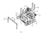
Fig.1 is a structural schematic view of a dual-axis platform for use in an unmanned aerial vehicle according to a first embodiment of the present invention; -
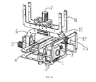
Fig.2 is explodedview 1 of a triple-axis platform for use in an unmanned aerial vehicle according to a second embodiment of the present invention; -
Fig.3 is explodedview 2 of a triple-axis platform for use in an unmanned aerial vehicle according to a second embodiment of the present invention; -
Fig.4 is explodedview 2 of a triple-axis platform for use in an unmanned aerial vehicle according to a second embodiment of the present invention; -
Fig.5 is structuralschematic view 1 of a triple-axis platform for use in an unmanned aerial vehicle according to a second embodiment of the present invention; -
Fig.6 is structuralschematic view 2 of a triple-axis platform for use in an unmanned aerial vehicle according to a second embodiment of the present invention; -
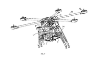
Fig.7 is explodedview 1 of a multi-rotor aircraft according to a third embodiment of the present invention; -
Fig.8 is explodedview 2 of a multi-rotor aircraft according to a third embodiment of the present invention; -
Fig.9 is structuralschematic view 1 of a multi-rotor aircraft according to a third embodiment of the present invention; -
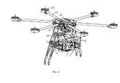
Fig. 10 is structuralschematic view 2 of a multi-rotor aircraft according to a third embodiment of the present invention; -
Fig.11 is structuralschematic view 1 of a platform for use in an unmanned aerial vehicle according to a fourth embodiment of the present invention; -
Fig.12 is structuralschematic view 2 of a platform for use in an unmanned aerial vehicle according to a fourth embodiment of the present invention; -
Fig.13 is structural schematic view 3 of a platform for use in an unmanned aerial vehicle according to a fourth embodiment of the present invention; -
Fig.14 is structuralschematic view 4 of a platform for use in an unmanned aerial vehicle according to a fourth embodiment of the present invention; - Specific embodiments of the present invention will be described in detail with reference to figures to make technical features, objects and effects of the present invention clearer to understand.
- In an embodiment as shown in
Fig.1 , the present invention provides a dual-axis platform for an unmanned aerial vehicle, comprising a machine frame assembly, a transmission assembly and ashooting assembly 1. The machine frame assembly comprises afirst bracket 2, asecond bracket 4 and athird bracket 6, theshooting assembly 1 is fixed on thefirst bracket 2, thefirst bracket 2 is rotatably arranged with thesecond bracket 4, and thesecond bracket 4 is rotatably arranged with thethird bracket 6. Here, the shape of theshooting assembly 1 is not limited to a square shape as shown inFig.1 , and it may be circular, oval, or in other shapes as commonly seen in the market. The transmission assembly comprises a first motor 3 and asecond motor 5, wherein the first motor 3 drives thefirst bracket 2 to rotate about its rotation axis relative to thesecond bracket 4, and thesecond motor 5 drives thesecond bracket 4 to rotate about its rotation axis relative to thethird bracket 6. A power source provided in the present embodiment is a motor. A small-sized motor as used has the following advantages: (1) the motor directly drives with less energy consumption, thereby saving energy and achieving environment protection; (2) the motor has a shorter response time and can timely and quickly adjust to adapt for various flying postures of the unmanned aerial vehicle so as to improve shooting stability of the shooting assembly. Two free ends of thesecond bracket 4 extend outward, thefirst bracket 2 and theshooting assembly 1 are integrally rotatably arranged between the two free ends; during rotation of thesecond bracket 4 driven by thesecond motor 5, the longer the length of the two free ends of thesecond bracket 4 is, the farther the center of gravity of thefirst bracket 2 and theshooting assembly 1 is away from a positioning point of thesecond bracket 4 so that the shaking of thesecond bracket 4 is stronger and theshooting assembly 1 is less stable. In order to reduce the shaking of thesecond bracket 4 and improve stability, as shown inFig.1 , the platform further comprises alinkage member 12 which two free ends are respectively rotatably arranged at two open ends of thesecond bracket 4, thelinkage member 12 being fixed on thethird bracket 6 via afastener 13. In the present invention, the free ends of thelinkage member 12 are hingedly arranged on thesecond bracket 4 to jointly form a parallelogram. According to principles of the parallelogram, when thesecond bracket 4 rotates a certain angle relative to thethird bracket 6, thelinkage member 12 rotates the same angle along with it without interfering with the movement trajectory of thesecond bracket 4; meanwhile thelinkage member 12 is fixed on thethird bracket 6 via afastener 13, thereby providing support and positioning of the two open ends of thesecond bracket 4 and increasing stability of thesecond bracket 4. The free ends of thelinkage member 12 are hingedly arranged on thesecond bracket 4 to jointly form a parallelogram. According to principles of the parallelogram, when thesecond bracket 4 rotates a certain angle relative to thethird bracket 6, thelinkage member 12 rotates the same angle along with it without interfering with the movement trajectory of thesecond bracket 4; meanwhile thelinkage member 12 is fixed on thethird bracket 6 via afastener 13, and thelinkage member 12 provides effective support for the two open ends of thesecond bracket 4 in a vertical direction, increases the load and rigidity of thesecond bracket 4 and effectively reduces deformation quantity when thesecond bracket 4 has a larger load, and meanwhile, reduces self weight of thesecond bracket 4 in respect of production process and decreases a diameter of thesecond motor 5. - On the basis of the above technical solution, specifically, the
linkage member 12 comprises afirst link 121, asecond link 122 and athird link 123 which are hingedly connected sequentially; one free end of thefirst link 121 is hingedly arranged at one end of thesecond bracket 4, one free end of thethird link 123 is hingedly arranged at the other end of thesecond bracket 4 so that thelinkage member 12 and the second bracket jointly form a parallelogram. In order to position the parallelogram and improve its stability, a middle portion of thesecond link 122 is positioned on thethird bracket 6 via thefastener 13. - Preferably, in order to enable a fixed connection between the
linkage member 12 and thethird bracket 6, as shown inFig.1 , it further includes a mountingarm 10, wherein one end of the mountingarm 10 is fixed on thethird bracket 6, the other end is provided with apositioning hole 11 adapted for thefastener 13, and thesecond link 122 is fixed on the mountingarm 10 via thefastener 13. - In order to facilitate the motor adjusting its rotation angle timely, preferably a rotation axis X of the
first bracket 2 is arranged perpendicular to a rotation axis Y of thesecond bracket 4. A stator of the first motor 3 is fixed on thefirst bracket 2, and a rotor of the first motor 3 is fixedly arranged with thesecond bracket 4, and the first motor 3 directly drives thesecond bracket 4 to bring thefirst bracket 2 to rotate relative to thesecond bracket 4. A stator of thesecond motor 5 is fixed on thethird bracket 6 and a rotor of thesecond motor 5 is fixedly arranged with thesecond bracket 4, and thesecond motor 5 directly drives thesecond bracket 4 to bring thesecond bracket 4 to rotate relative to thethird bracket 6. - Furthermore, to increase stability during the shooting of the
shooting assembly 1, a center of gravity of thefirst bracket 2 along with theshooting assembly 1 falls on the rotation axis of thefirst bracket 2. Through mechanics analysis, when the center of gravity of thefirst bracket 2 and theshooting assembly 1 falls on the rotation axis X of thefirst bracket 2, thefirst bracket 2 rotates to any angle and does not generate rotation moment, i.e., thefirst bracket 2 will not shake to and fro due to the moment and thereby stability of theshooting assembly 1 during rotation is increased. When the unmanned aerial vehicle operates stably, namely, when motor driving is not needed, thefirst bracket 2 and theshooting assembly 1 are also in a dynamic balance state. - Likewise, it is found by mechanics analysis that in order to increase stability and prevent a whole assembly rotating about the Y axis from generating the rotation moment, preferably a center of gravity of the
first bracket 2, thesecond bracket 4 and theshooting assembly 1 as a whole falls on the rotation axis of thesecond bracket 4, as shown inFig.1 . - On the basis of the above technical solution, preferably, the platform provided in the present embodiment is adapted for a small unmanned aerial vehicle for aerial photography and surveillance, and the first motor 3 and the
second motor 5 each are preferably a DC brushless motor. Advantages for using the DC brushless motor in the unmanned aerial vehicle lie in that (1) electronic commutation, in place of conventional mechanical commutation, enables reliable performance, permanent wear resistance, a lower malfunction rate and an increased service life by about six times than a brush motor; (2) the DC brushless motor is a static motor with a small non-load current; (3) a high efficiency; (4) a small size. - Furthermore, the transmission assembly further comprises a circuit board, an inertia sensor, a microprocessor and a signal line, wherein the inertia sensor comprises a gyro for detecting an angular speed signal and an accelerometer for detecting an acceleration signal, the microprocessor controls positive rotation, reverse rotation and a magnitude of rotation speed of the first motor 3 and the
second motor 5 according to the angular speed signal and the acceleration signal. The inertia sensor is set to monitor postures of the unmanned aerial vehicle timely and dynamically, control positive and reverse rotation of the motor quickly and timely so as to improve the shooting stability of the shooting assembly. - In another embodiment as shown in
Figs.2-6 , the present invention provides a triple-axis platform for use in an unmanned aerial vehicle, comprising a machine frame assembly, a transmission assembly and ashooting assembly 1. As shown inFig.2 , the machine frame assembly comprises afirst bracket 2, asecond bracket 4, athird bracket 6, and a connectingframe 8 for external mounting. Theshooting assembly 1 is fixed on thefirst bracket 2. To allow theshooting assembly 1 to rotate along X axis (the rotation axis of the first bracket 2), thefirst bracket 2 is rotatably arranged with thesecond bracket 4. Such rotational structure can achieve rise or bow rotation of theshooting assembly 1. In order to adapt for left tilt or right tile flight of the unmanned aerial vehicle during flying, theshooting assembly 1 rotates to the right or to the left correspondingly to ensure stability of photo taking or video shooting. As shown inFigs.5 and6 , thesecond bracket 4 is rotatably arranged with thethird bracket 6, leftward or rightward rotation of thesecond bracket 4 brings thefirst bracket 2 and theshooting assembly 1 to rotate wholly. To allow circumferential rotation of theshooting assembly 1 to perform rotatable shooting in a range of 360 degrees, the connectingframe 8 is fixed externally to a helicopter or a multi-rotor aircraft, and thethird bracket 6 may rotate about a Z axis relative to the connectingframe 8. The transmission assembly comprises a first motor 3, asecond motor 5 and athird motor 7, wherein the first motor 3 drives thefirst bracket 2 to rotate about its rotation axis relative to thesecond bracket 4, thesecond motor 5 drives thesecond bracket 4 to rotate about its rotation axis relative to thethird bracket 6, and thethird motor 7 drives thethird bracket 6 to rotate about its rotation axis Z relative to the connectingframe 8. A power source provided in the present embodiment is a motor. A small-sized motor as used has the following advantages: (1) the motor directly drives with less energy consumption, thereby saving energy and achieving environment protection; (2) the motor has a shorter response time and can timely and quickly adjust to adapt for various flying postures of the unmanned aerial vehicle so as to improve shooting stability of the shooting assembly. As shown inFig.2 ,Fig.3 andFig.4 , two free ends of thesecond bracket 4 extend outward, thefirst bracket 2 and theshooting assembly 1 are integrally rotatably arranged between the two free ends; during rotation of thesecond bracket 4 driven by thesecond motor 5, the longer the length of the two free ends of thesecond bracket 4 is, the farther a center of gravity of thefirst bracket 2 and theshooting assembly 1 is away from a positioning point of thesecond bracket 4 so that the shaking of thesecond bracket 4 is stronger and theshooting assembly 1 is less stable. In order to reduce the shaking of thesecond bracket 4 and improve stability, as shown inFig.2 ,Fig.3 andFig.4 , the platform further comprises alinkage member 12 which two free ends are respectively rotatably arranged at two open ends of thesecond bracket 4, thelinkage member 12 being fixed on thethird bracket 6 via afastener 13. In the present invention, the free ends of thelinkage member 12 are hingedly arranged on thesecond bracket 4 to jointly form a parallelogram. According to principles of the parallelogram, when thesecond bracket 4 rotates a certain angle relative to thethird bracket 6, thelinkage member 12 rotates the same angle along with it without interfering with the movement trajectory of thesecond bracket 4; meanwhile thelinkage member 12 is fixed on thethird bracket 6 via thefastener 13, thereby providing supporting and positioning for the two open ends of thesecond bracket 4 and increasing stability of thesecond bracket 4. The free ends of thelinkage member 12 are hingedly arranged on thesecond bracket 4 to jointly form a parallelogram. According to principles of the parallelogram, when thesecond bracket 4 rotates a certain angle relative to thethird bracket 6, thelinkage member 12 rotates the same angle along with it without interfering with the movement trajectory of thesecond bracket 4; meanwhile thelinkage member 12 is fixed on thethird bracket 6 via thefastener 13, and thelinkage member 12 provides effective support for the two open ends of thesecond bracket 4 in a vertical direction, increases the load and rigidity of thesecond bracket 4 and effectively reduces deformation quantity when thesecond bracket 4 has a larger load, and meanwhile, reduces self weight of thesecond bracket 4 in respect of production process and decreases a diameter of thesecond motor 5. - On the basis of the above technical solution, specifically, as shown in
Fig.2 , thelinkage member 12 comprises afirst link 121, asecond link 122 and athird link 123 which are hingedly connected sequentially; one free end of thefirst link 121 is hingedly arranged at one end of thesecond bracket 4, one free end of thethird link 123 is hingedly arranged at the other end of thesecond bracket 4 so that thelinkage member 12 and thesecond bracket 4 jointly form a parallelogram. In order to position the parallelogram and improve its stability, a middle portion of thesecond link 122 is positioned on thethird bracket 6 via thefastener 13. - Preferably, in order to enable a fixed connection between the
linkage member 12 and thethird bracket 6, as shown inFig.2 ,Fig.3 andFig.4 , it includes a mountingarm 10, one end of the mountingarm 10 is fixed on thethird bracket 6, the other end is provided with apositioning hole 11 adapted for thefastener 13, and thesecond link 122 is fixed on the mountingarm 10 via thefastener 13. - Preferably, a rotation axis X of the
first bracket 2, a rotation axis Y of thesecond bracket 4 and a rotation axis Z of thethird bracket 6 are arranged perpendicular to one another. As shown inFig.3 andFig.4 , a stator of the first motor 3 is fixed on thefirst bracket 2, and a rotor of the first motor 3 is fixedly arranged with thesecond bracket 4, and the first motor 3 directly drives thesecond bracket 4 to bring thefirst bracket 2 to rotate relative to thesecond bracket 4. As shown inFig.5 andFig.6 , a stator of thesecond motor 5 is fixed on thethird bracket 6 and a rotor of thesecond motor 5 is fixedly arranged with thesecond bracket 4, and thesecond motor 5 directly drives thesecond bracket 4 to bring thesecond bracket 4 to rotate relative to thethird bracket 6. As shown inFig.5 andFig.6 , a stator of thesecond motor 7 is fixed on the connectingframe 8, a rotor is fixedly connected to thethird bracket 6, and thethird motor 7 directly drives thethird bracket 6 to bring thethird bracket 6 to rotate about the Z axis relative to the connectingframe 8. A positioning frame 9 is fixedly disposed on the connectingframe 8 to position thethird motor 7. - Furthermore, to increase stability during the shooting of the
shooting assembly 1, a center of gravity of thefirst bracket 2 and theshooting assembly 1 falls on the rotation axis of thefirst bracket 2. Through mechanics analysis, when the center of gravity of thefirst bracket 2 and theshooting assembly 1 falls on the rotation axis X of thefirst bracket 2, thefirst bracket 2 rotates to any angle and does not generate a rotation moment, i.e., thefirst bracket 2 will not shake to and fro due to the moment and thereby stability of theshooting assembly 1 during rotation is increased. When the unmanned aerial vehicle operates stably, namely, when motor driving is not needed, thefirst bracket 2 and theshooting assembly 1 are also in a dynamic balance state. - Likewise, it is found by mechanics analysis that in order to increase stability and prevent a whole assembly rotating about the Y axis from generating the rotation moment, preferably a center of gravity of the
first bracket 2, thesecond bracket 4 and theshooting assembly 1 as a whole falls on the rotation axis of thesecond bracket 4, as shown inFig.1 . - Likewise, in order to prevent a whole assembly rotating about the Y axis from generating the rotation moment, a center of gravity of the
first bracket 2, thesecond bracket 4, thethird bracket 6 and theshooting assembly 1 as a whole falls on the rotation axis Z of thethird bracket 6, as shown inFig.5 andFig.6 . - On the basis of the above technical solution, preferably, the platform provided by the present embodiment is adapted for a small unmanned aerial vehicle for aerial photography and surveillance, and the first motor 3 and the
second motor 5 each are preferably a DC brushless motor. Advantages for using the DC brushless motor in the unmanned aerial vehicle lie in that (1) electronic commutation, in place of conventional mechanical commutation, achieves reliable performance, permanent wear resistance, a lower malfunction rate and an increased service life by about six times than a brush motor; (2) the DC brushless motor is a static motor with a small non-load current; (3) a high efficiency; (4) a small size. - Furthermore, the transmission assembly further comprises a circuit board, an inertia sensor, a microprocessor and a signal line, wherein the inertia sensor comprises a gyro for detecting an angular speed signal and an accelerometer for detecting an acceleration signal, the microprocessor controls positive rotation, reverse rotation and a magnitude of rotation speed of the first motor 3 and the
second motor 5 according to the angular speed signal and the acceleration signal. The inertia sensor is set to monitor postures of the unmanned aerial vehicle timely and dynamically, and control positive and reverse rotation of the motor quickly and timely so as to improve the shooting stability of the shooting assembly. - In a further embodiment as shown in
Fig.7-Fig.10 , the present invention provides a multi-rotor aircraft, comprising the triple-axis platform 100 for use in an unmanned aerial vehicle, amulti-rotor mounting frame 200 and a circuit device. Themulti-rotor mounting frame 200 comprises abase 21, at least threesupport arms 22 inserted and fixed on thebase 21, arotor member 23 fixed at one end of thesupport arm 22, and a plurality of support frames 24 which are arranged extending along thebase 21 and used for positioning externally. Noticeably, the number of thesupport arms 22 is not limited to three as shown in the figures, and it may be four, six or eight. Thesupport arms 22 may be fixed on thebase 21 by insertion connection, welding, threaded connection or riveting. The triple-axis platform 100 for use in an unmanned aerial vehicle is fixedly arranged at the base 21 through the connectingframe 8. - Noticeably, the triple-
axis platform 100 of the multi-rotor aircraft employs the structure of the triple-axis platform for use in an unmanned aerial vehicle provided inembodiment 2, which is not detailed here. For particulars, please refer to the preceding depictions. - In an embodiment shown in
Fig.11 , the preset invention provides a platform for use in an unmanned aerial vehicle. The platform is a dual-axis platform comprising a machine frame assembly, a transmission assembly and ashooting assembly 1. The machine frame assembly comprises afirst bracket 2, asecond bracket 4, athird bracket 6 and alinkage member 12, the shooting assembly is fixed on thefirst bracket 2, thefirst bracket 2 is rotatably arranged with thesecond bracket 4, thesecond bracket 4 is rotatably arranged with thethird bracket 6, and thelinkage member 12 and thesecond bracket 4 form a four-link mechanism. The transmission assembly comprises a first motor 3 and afourth motor 25, wherein the first motor 3 directly drives thefirst bracket 2 to rotate relative to thesecond bracket 4. Different fromEmbodiment 1,Embodiment 2 and Embodiment 3, thefastener 13 is replaced by thefourth motor 25 which directly drives thelinkage member 12 to bring thesecond bracket 4 to rotate relative to thethird bracket 6, rather than the fact that thesecond motor 25 directly drives thefourth bracket 4 as inEmbodiment 1,Embodiment 2 and Embodiment 3. In the present invention, thelinkage member 12 and thesecond bracket 4 form a four-link mechanism, thefourth motor 25 which directly drives thelinkage member 12 to bring thesecond bracket 4 to rotate relative to thethird bracket 6, thelinkage member 12 and thesecond bracket 4 rotate the same angle without interfering with the movement trajectory of thesecond bracket 4; meanwhile thelinkage member 12 provides effective support for the two open ends of thesecond bracket 4 in a vertical direction, increases the load and rigidity of thesecond bracket 4, effectively reduces deformation quantity, and decreases the self weight of thesecond bracket 4. - In a further embodiment as shown in
Fig.12 , the present invention provides a triple-axis platform. Different from the dual-axis platform as described inFig.11 , the machine frame assembly of the platform for use in the unmanned aerial vehicle further comprises a connectingframe 8 for external mounting, the transmission assembly further comprises athird motor 7; thethird motor 7 drives thethird bracket 6 to rotate relative to the connectingframe 8. To allow circumferential rotation of theshooting assembly 1 to perform rotatable shooting in a range of 360 degrees, the connectingframe 8 is fixed externally to a helicopter or a multi-rotor aircraft, and thethird bracket 6 may rotate about a Z axis relative to the connectingframe 8. - In a further embodiment as shown in
Fig.13 , the present invention provides a dual-axis platform for use in an unmanned aerial vehicle. Different from the platform as described inFig.11 , the transmission assembly of the platform for use in an unmanned aerial vehicle further comprises asecond motor 5 which directly drives thesecond bracket 4 to rotate relative to thethird bracket 6. Thesecond motor 5 may serve as an auxiliary power source and drive thesecond bracket 4 in cooperation with thefourth motor 25. Since thelinkage member 12 and thesecond bracket 4 form a four-link mechanism, thesecond motor 5 and thefourth motor 24 are used in cooperation to synchronously drive thesecond bracket 4 to rotate. It may be understood that thesecond motor 5 and thefourth motor 25 may individually drive thesecond bracket 5 to rotate. - In a further embodiment as shown in
Fig.14 , the present invention provides a triple-axis platform for use in an unmanned aerial vehicle. Different from the platform as described inFig.13 , the machine frame assembly of the platform for use in the unmanned aerial vehicle further comprises a connectingframe 8 for external mounting, the transmission assembly further comprises athird motor 7; thethird motor 7 drives thethird bracket 6 to rotate relative to the connectingframe 8. To allow circumferential rotation of theshooting assembly 1 to perform rotatable shooting in a range of 360 degrees, the connectingframe 8 is fixed externally to a helicopter or a multi-rotor aircraft, and thethird bracket 6 may rotate about a Z axis relative to the connectingframe 8. - In the platform of
Embodiment 4 of the present invention, thelinkage member 12 and thesecond bracket 4 form a four-link mechanism, thefourth motor 25 directly drives thelinkage member 12 to bring thesecond bracket 4 to rotate relative to thethird bracket 6, thelinkage member 12 and thesecond bracket 4 rotate the same angle without interfering with the movement trajectory of thesecond bracket 4; meanwhile thelinkage member 12 provides effective support for the two open ends of thesecond bracket 4 in a vertical direction, increases the load and rigidity of thesecond bracket 4, effectively reduces deformation quantity, and decreases the self weight of thesecond bracket 4. Meanwhile, the motor, as the power source, is directly connected to the machine frame assembly of the platform, thereby consuming less energy and saving electrical energy; meanwhile, motor driving can achieve indefinitely variable adjustment, the motor has a shorter action response time and can quickly start, stop or adjust the magnitude of the rotation speed timely to adapt for various flying postures of the unmanned aerial vehicle so as to improve the shooting stability of the shooting assembly. - The above only describes preferred embodiments of the present invention with reference to figures. The protection scope of the present invention is not limited to the above specific embodiments. The above specific embodiments are only illustrative not restrictive. As suggested by the present invention, those having ordinary skill in the art, without departure from the essence of the present invention and the scope defined by appended claims, may devise many forms, which all fall within the scope of the present invention.
| 100 | 200 |
| 1 | 2 first bracket |
| 3 | 4 |
| 5 | 6 |
| 7 | 8 connecting frame |
| 9 | 10 |
| 11 | 12 |
| 121 | 122 |
| 123 | 13 |
| 21 | 22 |
| 23 | 24 |
| 25 fourth motor |
Claims (16)
- A dual-axis platform for use in an unmanned aerial vehicle, comprising a machine frame assembly, a transmission assembly and a shooting assembly (1), characterized in that:the machine frame assembly comprises a first bracket (2), a second bracket (4) and a third bracket (6), wherein the shooting assembly (1) is fixed on the first bracket (2), the first bracket (2) is rotatably arranged with the second bracket (4), and the second bracket (4) is rotatably arranged with the third bracket (6);the transmission assembly comprises a first motor (3) and a second motor (5), wherein the first motor (3) drives the first bracket (2) to rotate relative to the second bracket (4), and the second motor (5) drives the second bracket (4) to rotate relative to the third bracket (6);and further comprises a linkage member (12) with two free ends respectively rotatably arranged at two open ends of the second bracket (4), the linkage member (12) being fixed on the third bracket (6) via a fastener (13).
- The dual-axis platform for use in an unmanned aerial vehicle according to claim 1, characterized in that, the linkage member (12) comprises a first link (121), a second link (122) and a third link (123) hingedly connected sequentially; one free end of the first link (121) is hingedly arranged at one end of the second bracket (4), one free end of the third link (123) is hingedly arranged at the other end of the second bracket (4); a middle portion of the second link (122) is positioned on the third bracket (6) via the fastener (13).
- The dual-axis platform for use in an unmanned aerial vehicle according to claim 2, characterized in that, it further comprises a mounting arm (10), wherein one end of the mounting arm (10) is fixed on the third bracket (6), and the other end is provided with a positioning hole (11) adapted for the fastener (13), and wherein the second link (122) is fixed on the mounting arm (10) via the fastener (13).
- The dual-axis platform for use in an unmanned aerial vehicle according to claim 1, characterized in that, a stator of the first motor (3) is fixed on the first bracket (2), and a rotor of the first motor (3) is fixedly arranged with the second bracket (4); a stator of the second motor (5) is fixed on the third bracket (6), and a rotor of the second motor (5) is fixedly arranged with the second bracket (4).
- The dual-axis platform for use in an unmanned aerial vehicle according to claim 1, characterized in that, the center of gravity of the first bracket (2) and the shooting assembly (1) falls on a rotation axis of the first bracket (2).
- The dual-axis platform for use in an unmanned aerial vehicle according to claim 1, characterized in that, the center of gravity of the first bracket (2), the second bracket (4) and the shooting assembly (1) as a whole falls on a rotation axis of the second bracket (4).
- A tri-axis platform for use in an unmanned aerial vehicle, comprising a machine frame assembly, a transmission assembly and a shooting assembly (1), characterized in that:the machine frame assembly comprises a first bracket (2), a second bracket (4), a third bracket (6) and a connecting frame (8) for external mounting, wherein the shooting assembly (1) is fixed on the first bracket (2), the first bracket (2) is rotatably arranged with the second bracket (4), and the second bracket (4) is rotatably arranged with the third bracket (6);the transmission assembly comprises a first motor (3), a second motor (5) and a third motor (7), wherein the first motor (3) drives the first bracket (2) to rotate relative to the second bracket (4), the second motor (5) drives the second bracket (4) to rotate relative to the third bracket (6), and the third motor (7) drives the third bracket (6) to rotate relative to the connecting frame (8);it further comprises a linkage member (12) with two free ends rotatably arranged at two open ends of the second bracket (4) respectively, the linkage member (12) being fixed on the third bracket (6) via a fastener (13).
- The tri-axis platform for use in an unmanned aerial vehicle according to claim 7, characterized in that, the linkage member (12) comprises a first link (121), a second link (122) and a third link (123) hingedly connected sequentially; one free end of the first link (121) is hingedly arranged at one end of the second bracket (4), one free end of the third link (123) is hingedly arranged at the other end of the second bracket (4); a middle portion of the second link (122) is positioned on the third bracket (6) via the fastener (13).
- The tri-axis platform for use in an unmanned aerial vehicle according to claim 8, characterized in that, it further comprises a mounting arm (10), wherein one end of the mounting arm (10) is fixed on the third bracket (6), and the other end is provided with a positioning hole (11) adapted for the fastener (13), and wherein the second link (122) is fixed on the mounting arm (10) via the fastener (13).
- A multi-rotor aerial vehicle, characterized in that it comprises the tri-axis platform (100) for use in an unmanned aerial vehicle according to any one of claims 7-9, a multi-rotor mounting frame (200) and circuit elements, the multi-rotor mounting frame (200) comprises a base (21), at least three support arms (22) inserted and fixed on the base (21), a rotor member (23) fixed at one end of each support arm (22), and a plurality of support frames (24) which are arranged extending along the base (21) and used for positioning externally; the tri-axis platform (100) for use in an unmanned aerial vehicle is fixedly arranged at the base (21) through the connecting frame (8).
- A platform for use in an unmanned aerial vehicle, comprising a machine frame assembly, a transmission assembly and a shooting assembly (1), characterized in that:the machine frame assembly comprises a first bracket (2), a second bracket (4), a third bracket (6) and a linkage member (12), wherein the shooting assembly (1) is fixed on the first bracket (2), the first bracket (2) is rotatably arranged with the second bracket (4), the second bracket (4) is rotatably arranged with the third bracket (6), and the linkage member (12) and the second bracket (4) form a four-link mechanism;the transmission assembly comprises a first motor (3) and a fourth motor (25), wherein the first motor (3) directly drives the first bracket (2) to rotate relative to the second bracket (4), and the fourth motor (25) directly drives the linkage member (12) to thereby bring the second bracket (4) into rotation relative to the third bracket (6).
- The platform for use in an unmanned aerial vehicle according to claim 11, characterized in that, the linkage member (12) comprises a first link (121), a second link (122) and a third link (123) hingedly connected sequentially; one free end of the first link (121) is hingedly arranged at one end of the second bracket (4), one free end of the third link (123) is hingedly arranged at the other end of the second bracket (4); the second link (122) is positioned on the third bracket (6) via the fourth motor (25).
- The platform for use in an unmanned aerial vehicle according to claim 12, characterized in that, it further comprises a mounting arm (10), wherein one end of the mounting arm (10) is fixed on the third bracket (6), and the other end is fixedly connected to a stator of the fourth motor (25); a rotor of the fourth motor (25) is fixedly connected to the second link (122);
or, one end of the mounting arm (10) is fixed on the third bracket (6), and the other end is fixedly connected to the rotor of the fourth motor (25); the stator of the fourth motor (25) is fixedly connected to the second link (122). - The platform for use in an unmanned aerial vehicle according to claim 12, characterized in that, the second bracket (4) is in an open "U" shape, and one free end of the first link (121) and one free end of the third link (123) are respectively rotatably arranged at two open ends of the second bracket (4).
- The platform for use in an unmanned aerial vehicle according to claim 11, characterized in that, the machine frame assembly further comprises a connecting frame (8) for external mounting, and the transmission assembly further comprises a third motor (7); the third motor (7) drives the third bracket (6) to rotate relative to the connecting frame (8).
- The platform for use in an unmanned aerial vehicle according to any one of claims 11-15, characterized in that, the transmission assembly further comprises a second motor (5) which directly drives the second bracket (4) to rotate relative to the third bracket (6).
Applications Claiming Priority (2)
| Application Number | Priority Date | Filing Date | Title |
|---|---|---|---|
| CN201110268445 | 2011-09-09 | ||
| PCT/CN2011/079703 WO2013033924A1 (en) | 2011-09-09 | 2011-09-15 | Dual-axis ball head for use in unmanned aerial vehicle, triple-axis ball head for use in unmanned aerial vehicle, and multi-rotor aerial vehicle |
Publications (3)
| Publication Number | Publication Date |
|---|---|
| EP2759479A1 true EP2759479A1 (en) | 2014-07-30 |
| EP2759479A4 EP2759479A4 (en) | 2015-06-17 |
| EP2759479B1 EP2759479B1 (en) | 2017-03-15 |
Family
ID=46667299
Family Applications (1)
| Application Number | Title | Priority Date | Filing Date |
|---|---|---|---|
| EP11871956.6A Active EP2759479B1 (en) | 2011-09-09 | 2011-09-15 | Dual-axis ball head for use in unmanned aerial vehicle, triple-axis ball head for use in unmanned aerial vehicle, and multi-rotor aerial vehicle |
Country Status (10)
| Country | Link |
|---|---|
| EP (1) | EP2759479B1 (en) |
| JP (1) | JP6362539B2 (en) |
| KR (1) | KR101749996B1 (en) |
| CN (2) | CN102996983B (en) |
| AU (1) | AU2011376582B2 (en) |
| BR (1) | BR112014005378B1 (en) |
| CA (1) | CA2848221A1 (en) |
| MX (1) | MX352250B (en) |
| RU (1) | RU2572946C2 (en) |
| WO (1) | WO2013033924A1 (en) |
Cited By (6)
| Publication number | Priority date | Publication date | Assignee | Title |
|---|---|---|---|---|
| CN103754381A (en) * | 2014-01-23 | 2014-04-30 | 徐鹏 | Multi-lens aerial camera shooting stabilized platform |
| CN104973261A (en) * | 2015-07-10 | 2015-10-14 | 北京中科遥数信息技术有限公司 | Unmanned aerial vehicle three-axis autostability holder capable of dynamically recording adjustment amount |
| WO2016038204A1 (en) * | 2014-09-12 | 2016-03-17 | Hochschule für Angewandte Wissenschaften Hamburg | Decentralized redundant architecture for an unmanned aircraft for simplified integration of sensor systems |
| CN105626734A (en) * | 2016-03-02 | 2016-06-01 | 深圳市高巨创新科技开发有限公司 | Vibration reducing device of unmanned aerial vehicle |
| WO2019007835A1 (en) * | 2017-07-03 | 2019-01-10 | Swarm Systems Limited | Perched air vehicle that pans |
| EP3770680A1 (en) * | 2014-08-13 | 2021-01-27 | SZ DJI Osmo Technology Co., Ltd. | Gimbal platform |
Families Citing this family (55)
| Publication number | Priority date | Publication date | Assignee | Title |
|---|---|---|---|---|
| EP2759479B1 (en) * | 2011-09-09 | 2017-03-15 | SZ DJI Technology Co., Ltd. | Dual-axis ball head for use in unmanned aerial vehicle, triple-axis ball head for use in unmanned aerial vehicle, and multi-rotor aerial vehicle |
| WO2013033954A1 (en) | 2011-09-09 | 2013-03-14 | 深圳市大疆创新科技有限公司 | Gyroscopic dynamic auto-balancing ball head |
| CN104076825B (en) * | 2013-03-31 | 2018-11-16 | 深圳市大疆创新科技有限公司 | Driving device, carrier for application of driving device and control method thereof |
| CN104995090B (en) | 2013-03-31 | 2017-05-03 | 深圳市大疆创新科技有限公司 | payload mounting platform |
| CN104075084B (en) * | 2013-03-31 | 2016-08-17 | 深圳市大疆创新科技有限公司 | Load-carrying body |
| CN104075085B (en) * | 2013-03-31 | 2016-08-17 | 深圳市大疆创新科技有限公司 | Load-carrying body |
| US8903568B1 (en) | 2013-07-31 | 2014-12-02 | SZ DJI Technology Co., Ltd | Remote control method and terminal |
| CN104456003B (en) * | 2013-09-18 | 2016-04-06 | 深圳市大疆创新科技有限公司 | Multiple bay |
| JP2016541026A (en) | 2013-10-08 | 2016-12-28 | エスゼット ディージェイアイ テクノロジー カンパニー リミテッドSz Dji Technology Co.,Ltd | Apparatus and method for stabilization and vibration reduction |
| CN103523241A (en) * | 2013-10-15 | 2014-01-22 | 江苏艾锐泰克无人飞行器科技有限公司 | Brushless tripod head of unmanned aerial vehicle |
| WO2015085499A1 (en) | 2013-12-10 | 2015-06-18 | 深圳市大疆创新科技有限公司 | Non-orthogonal axis carrier |
| CN103754379B (en) * | 2014-01-22 | 2016-02-10 | 徐鹏 | A kind of automatic photography stable platform of many lens aerial |
| CN103984193B (en) * | 2014-03-14 | 2020-10-16 | 广州虹天航空科技有限公司 | Photographing apparatus stabilizer and control method thereof |
| CN104603516B (en) * | 2014-03-19 | 2016-06-01 | 深圳市大疆创新科技有限公司 | Cloud platform |
| CN112429255A (en) | 2014-04-28 | 2021-03-02 | 深圳市大疆创新科技有限公司 | Handheld Platform |
| CN104049440B (en) * | 2014-06-13 | 2017-02-22 | 桂林智神信息技术有限公司 | Moving camera stabilizer and stability control method thereof |
| CN104019348A (en) * | 2014-06-23 | 2014-09-03 | 张锦海 | Handheld three-axis self-stabilization shooting tripod head |
| CN105223967B (en) * | 2014-06-30 | 2017-11-28 | 深圳市大疆灵眸科技有限公司 | A kind of camera shooting control method, device and tripod head equipment |
| CN105323535A (en) * | 2014-07-28 | 2016-02-10 | 中兴通讯股份有限公司 | Video conference terminal stability control method and video conference terminal |
| CN104390110A (en) * | 2014-11-04 | 2015-03-04 | 南京航空航天大学 | Tri-axial dynamic self-stabilizing cradle head and working method thereof |
| CN105518369B (en) | 2014-11-28 | 2018-02-02 | 深圳市大疆灵眸科技有限公司 | Translation shaft assembly and its head used |
| CN104656684A (en) * | 2015-01-20 | 2015-05-27 | 桂林飞宇电子科技有限公司 | Method for controlling tri-axis stabilization tripod head with brushless motors by using single IMU sensors |
| CN104670512B (en) * | 2015-02-13 | 2017-06-20 | 广州市红鹏直升机遥感科技有限公司 | A kind of many camera lens holder for aerial photographing |
| CN104908944B (en) * | 2015-06-10 | 2017-03-01 | 浙江空行飞行器技术有限公司 | A kind of unmanned plane of recordable accident |
| CN107005102B (en) | 2015-08-14 | 2019-09-27 | 深圳市大疆灵眸科技有限公司 | System and method for supporting a compact servo system |
| JP6310569B2 (en) | 2015-09-11 | 2018-04-11 | エスゼット ディージェイアイ オスモ テクノロジー カンパニー リミテッドSZ DJI Osmo Technology Co., Ltd. | Support mechanism |
| CN113581464A (en) | 2015-09-11 | 2021-11-02 | 深圳市大疆灵眸科技有限公司 | Carrier for unmanned aerial vehicle |
| JP2017067878A (en) * | 2015-09-29 | 2017-04-06 | 日本電産サンキョー株式会社 | Image pickup apparatus |
| CN108351574B (en) | 2015-10-20 | 2020-12-22 | 深圳市大疆创新科技有限公司 | System, method and apparatus for setting camera parameters |
| CN107089344B (en) * | 2015-12-10 | 2019-10-11 | 安徽伯希和户外装备用品有限公司 | Anti-seismic camera for aircraft |
| CN105416558B (en) * | 2015-12-11 | 2018-02-27 | 广州极飞科技有限公司 | Unmanned plane frame, unmanned plane and augmentation control method |
| CN105546291B (en) * | 2016-03-10 | 2017-09-01 | 上海锐拍智能科技有限公司 | A kind of hand-held shooting, the gravity balance mechanism of photography auxiliary stabilizer |
| KR101689197B1 (en) * | 2016-06-20 | 2016-12-23 | 주식회사 엠지아이티 | Gimbal assembly for drone |
| WO2018023328A1 (en) * | 2016-08-01 | 2018-02-08 | 深圳市道通智能航空技术有限公司 | Cradle head and unmanned aerial vehicle |
| CN106275478B (en) * | 2016-09-08 | 2018-06-12 | 四川建筑职业技术学院 | A kind of slide rail type three-axis stabilization holder |
| CN106628245B (en) * | 2016-10-26 | 2023-03-14 | 华南农业大学 | An indoor agricultural drone test platform |
| CN107735320B (en) * | 2016-11-04 | 2021-01-05 | 深圳市道通智能航空技术有限公司 | Cloud platform and unmanned aerial vehicle |
| CN109751492B (en) * | 2016-12-28 | 2021-07-20 | 深圳市大疆灵眸科技有限公司 | Pan-tilt frame, pan-tilt and photographing device having the pan-tilt frame |
| CN106933254B (en) * | 2017-03-03 | 2020-05-19 | 鞍山天源科技有限公司 | Frameless spherical holder device |
| CN108702432B (en) * | 2017-09-11 | 2020-12-29 | 深圳市大疆创新科技有限公司 | PTZ camera and UAV with the PTZ camera |
| CN108575032A (en) * | 2017-10-26 | 2018-09-25 | 常州星宇车灯股份有限公司 | A New Balanced Light System |
| CN108058839A (en) * | 2017-12-25 | 2018-05-22 | 陈益德 | A multi-axis freely adjustable UAV platform |
| CN108341056B (en) * | 2017-12-30 | 2024-05-07 | 浙江大学 | A kind of agricultural monitoring drone |
| CN108488572A (en) * | 2018-05-23 | 2018-09-04 | 高新兴科技集团股份有限公司 | A kind of active stabilization holder and its control method |
| CN108983827A (en) * | 2018-09-14 | 2018-12-11 | 高新兴科技集团股份有限公司 | A kind of Self-stabilization holder |
| CN109618079A (en) * | 2018-12-07 | 2019-04-12 | 高新兴科技集团股份有限公司 | A kind of ball machine based on direct driving motor driving |
| CN110001986A (en) * | 2019-04-24 | 2019-07-12 | 太原科技大学 | A kind of twin shaft holder based on steering engine transmission |
| CN110901952A (en) * | 2019-11-29 | 2020-03-24 | 北京电子工程总体研究所 | Three-degree-of-freedom unmanned aerial vehicle testing device and system |
| WO2022077357A1 (en) * | 2020-10-15 | 2022-04-21 | 深圳市大疆创新科技有限公司 | Detection method and apparatus for gimbal, and gimbal, movable platform and storage medium |
| JP2022125967A (en) * | 2021-02-17 | 2022-08-29 | 望月 貴里子 | Rotary mechanism, flight body, attitude control device of loaded object, and method |
| EP4296160A4 (en) * | 2021-02-17 | 2025-03-12 | Mochizuki, Leona | ROTATION MECHANISM, AIRCRAFT, AND DEVICE AND METHOD FOR CONTROLLING THE POSITION OF A LOAD |
| JP2022126001A (en) * | 2021-02-17 | 2022-08-29 | 望月 玲於奈 | Rotating mechanism, flight body, attitude control device of loaded object, method |
| CN113665800A (en) * | 2021-07-26 | 2021-11-19 | 北京中天博地科技有限公司 | A 3D automatic modeling method based on private cloud without image control |
| CN114198455A (en) * | 2021-12-15 | 2022-03-18 | 上海新纪元机器人有限公司 | Self-balancing vibration damping system mounted on carrying equipment |
| KR102604834B1 (en) * | 2023-02-23 | 2023-11-22 | (유)동아하이테크 | A horizontal maintaining apparatus and a drone delivery unit comprising the same |
Family Cites Families (29)
| Publication number | Priority date | Publication date | Assignee | Title |
|---|---|---|---|---|
| JPS6288898A (en) * | 1985-10-14 | 1987-04-23 | 松下電器産業株式会社 | television camera equipment |
| US4752791A (en) * | 1987-07-28 | 1988-06-21 | Allred Charles N | Camera mount |
| FR2656730A1 (en) * | 1990-01-02 | 1991-07-05 | Ema For You | Device for stabilizing and/or orientating means for acquiring data and method implementing the said device |
| US5426476A (en) * | 1994-11-16 | 1995-06-20 | Fussell; James C. | Aircraft video camera mount |
| FR2730570B1 (en) * | 1995-02-10 | 1997-03-28 | Hartmann Pascal | BALANCED AND AERIAL PICTURE CONTROL DEVICE |
| US5966991A (en) * | 1997-04-23 | 1999-10-19 | Universite Laval | Two degree-of-freedom spherical orienting device |
| IL141156A (en) * | 2001-01-29 | 2005-05-17 | Top I Vision Ltd | Stabilizing system for an image-producing means |
| JP4319844B2 (en) | 2003-02-07 | 2009-08-26 | 日本放送協会 | Aerial camera pan head |
| CN2689286Y (en) * | 2004-03-20 | 2005-03-30 | 云南省电子计算中心 | Gyroscopic pan with dynamic balance for aerial camera |
| JP4383237B2 (en) * | 2004-04-28 | 2009-12-16 | 株式会社日立製作所 | Self-position detection device, in-furnace inspection method and in-furnace inspection device using the same |
| JP4532318B2 (en) * | 2005-03-25 | 2010-08-25 | ヤマハ発動機株式会社 | Unmanned helicopter |
| US8179078B2 (en) * | 2005-04-27 | 2012-05-15 | Sidman Adam D | Handheld or vehicle-mounted platform stabilization system |
| US8087315B2 (en) * | 2006-10-10 | 2012-01-03 | Honeywell International Inc. | Methods and systems for attaching and detaching a payload device to and from, respectively, a gimbal system without requiring use of a mechanical tool |
| JP2008167257A (en) * | 2006-12-28 | 2008-07-17 | Mitsumi Electric Co Ltd | Pan / tilt device |
| CN100590748C (en) * | 2007-07-05 | 2010-02-17 | 浙江大学 | A two-degree-of-freedom aerial camera platform based on a model helicopter |
| RU2369535C1 (en) * | 2008-02-28 | 2009-10-10 | Федеральное государственное унитарное предприятие "Центральный научно-исследовательский институт машиностроения" (ФГУП ЦНИИмаш) | Method of optimising dynamic conditions for operation of gravity-sensitive installations in conditions of microacceleration on-board orbiting spacecraft and device to this end |
| US8322648B2 (en) * | 2008-05-15 | 2012-12-04 | Aeryon Labs Inc. | Hovering aerial vehicle with removable rotor arm assemblies |
| GB2464147B (en) * | 2008-05-29 | 2013-01-09 | Kevin Knowles | Three degree-of-freedom parallel spherical mechanism for payload orienting applications |
| JP2010039350A (en) | 2008-08-07 | 2010-02-18 | Tamagawa Seiki Co Ltd | Structure for adjusting weight balance of space stabilizing device |
| DE102008039468A1 (en) * | 2008-08-25 | 2010-03-04 | Stefan Reich | Device and method for stabilizing the position of cameras |
| CN201287830Y (en) * | 2008-10-14 | 2009-08-12 | 西安展翼航空科技有限公司 | Stabilising bracket for aerial photography camera |
| CN101403848A (en) * | 2008-11-14 | 2009-04-08 | 天津市联大通讯发展有限公司 | Three-dimensional automatic stabilization camera shooting system |
| CN201380965Y (en) * | 2009-04-28 | 2010-01-13 | 中国农业科学院农业资源与农业区划研究所 | Aerial photography gimbal on small unmanned aircraft |
| CN201626554U (en) * | 2009-12-07 | 2010-11-10 | 深圳市大疆创新科技有限公司 | Three-freedom-degree inertia stabilization aerial photography cradle head |
| CN101734377A (en) * | 2009-12-15 | 2010-06-16 | 深圳市大疆创新科技有限公司 | Three-degree-of-freedom aerial photographic head with stable inertia |
| CN201604796U (en) * | 2010-03-23 | 2010-10-13 | 贵阳帝三数字技术有限公司 | Intelligent aerial photography unmanned aerial vehicle |
| CN101811578B (en) * | 2010-04-23 | 2013-10-23 | 国家电网公司 | Special photoelectric nacelle of power patrol unmanned helicopter |
| KR101042200B1 (en) | 2010-09-02 | 2011-06-16 | 드림스페이스월드주식회사 | Unmanned Vehicle Using a PC |
| EP2759479B1 (en) * | 2011-09-09 | 2017-03-15 | SZ DJI Technology Co., Ltd. | Dual-axis ball head for use in unmanned aerial vehicle, triple-axis ball head for use in unmanned aerial vehicle, and multi-rotor aerial vehicle |
-
2011
- 2011-09-15 EP EP11871956.6A patent/EP2759479B1/en active Active
- 2011-09-15 WO PCT/CN2011/079703 patent/WO2013033924A1/en not_active Ceased
- 2011-09-15 BR BR112014005378-2A patent/BR112014005378B1/en not_active IP Right Cessation
- 2011-09-15 JP JP2014528828A patent/JP6362539B2/en not_active Expired - Fee Related
- 2011-09-15 MX MX2014002730A patent/MX352250B/en active IP Right Grant
- 2011-09-15 CA CA2848221A patent/CA2848221A1/en not_active Abandoned
- 2011-09-15 AU AU2011376582A patent/AU2011376582B2/en not_active Ceased
- 2011-09-15 KR KR1020147009446A patent/KR101749996B1/en not_active Expired - Fee Related
- 2011-09-15 RU RU2014113930/11A patent/RU2572946C2/en active
- 2011-11-18 CN CN201110380344.6A patent/CN102996983B/en active Active
- 2011-11-18 CN CN2011204761249U patent/CN202392373U/en not_active Expired - Lifetime
Cited By (8)
| Publication number | Priority date | Publication date | Assignee | Title |
|---|---|---|---|---|
| CN103754381A (en) * | 2014-01-23 | 2014-04-30 | 徐鹏 | Multi-lens aerial camera shooting stabilized platform |
| EP3770680A1 (en) * | 2014-08-13 | 2021-01-27 | SZ DJI Osmo Technology Co., Ltd. | Gimbal platform |
| US11422439B2 (en) | 2014-08-13 | 2022-08-23 | Sz Dji Osmo Technology Co., Ltd. | Gimbal |
| WO2016038204A1 (en) * | 2014-09-12 | 2016-03-17 | Hochschule für Angewandte Wissenschaften Hamburg | Decentralized redundant architecture for an unmanned aircraft for simplified integration of sensor systems |
| CN104973261A (en) * | 2015-07-10 | 2015-10-14 | 北京中科遥数信息技术有限公司 | Unmanned aerial vehicle three-axis autostability holder capable of dynamically recording adjustment amount |
| CN105626734A (en) * | 2016-03-02 | 2016-06-01 | 深圳市高巨创新科技开发有限公司 | Vibration reducing device of unmanned aerial vehicle |
| CN105626734B (en) * | 2016-03-02 | 2018-11-13 | 深圳市高巨创新科技开发有限公司 | The damping device of unmanned vehicle |
| WO2019007835A1 (en) * | 2017-07-03 | 2019-01-10 | Swarm Systems Limited | Perched air vehicle that pans |
Also Published As
| Publication number | Publication date |
|---|---|
| KR20140092812A (en) | 2014-07-24 |
| CN202392373U (en) | 2012-08-22 |
| BR112014005378A2 (en) | 2017-03-28 |
| EP2759479A4 (en) | 2015-06-17 |
| RU2014113930A (en) | 2015-10-20 |
| BR112014005378B1 (en) | 2020-12-08 |
| CN102996983A (en) | 2013-03-27 |
| RU2572946C2 (en) | 2016-01-20 |
| MX2014002730A (en) | 2014-07-09 |
| MX352250B (en) | 2017-11-15 |
| KR101749996B1 (en) | 2017-06-22 |
| JP2015523930A (en) | 2015-08-20 |
| AU2011376582A1 (en) | 2014-04-24 |
| JP6362539B2 (en) | 2018-07-25 |
| CN102996983B (en) | 2016-04-06 |
| AU2011376582B2 (en) | 2016-12-15 |
| EP2759479B1 (en) | 2017-03-15 |
| CA2848221A1 (en) | 2013-03-14 |
| WO2013033924A1 (en) | 2013-03-14 |
Similar Documents
| Publication | Publication Date | Title |
|---|---|---|
| AU2011376582B2 (en) | Dual-axis platform for use in an unmanned aerial vehicle, Tri-axis platform for use in an unmanned aerial vehicle, and multi-rotor aerial vehicle | |
| CN202295294U (en) | Cradle head for unmanned aerial vehicle | |
| CN202392374U (en) | Gyroscopic dynamic self-balancing pan/tilt/zoom (PTZ) | |
| US11140322B2 (en) | Stabilizing platform | |
| WO2018201718A1 (en) | Photographic component and unmanned vehicle | |
| CN106464079A (en) | A cloud platform and unmanned aerial vehicle | |
| CN206504075U (en) | Head, portable equipment and aircraft |
Legal Events
| Date | Code | Title | Description |
|---|---|---|---|
| PUAI | Public reference made under article 153(3) epc to a published international application that has entered the european phase |
Free format text: ORIGINAL CODE: 0009012 |
|
| 17P | Request for examination filed |
Effective date: 20140409 |
|
| AK | Designated contracting states |
Kind code of ref document: A1 Designated state(s): AL AT BE BG CH CY CZ DE DK EE ES FI FR GB GR HR HU IE IS IT LI LT LU LV MC MK MT NL NO PL PT RO RS SE SI SK SM TR |
|
| DAX | Request for extension of the european patent (deleted) | ||
| RA4 | Supplementary search report drawn up and despatched (corrected) |
Effective date: 20150515 |
|
| RIC1 | Information provided on ipc code assigned before grant |
Ipc: F16M 11/12 20060101ALI20150508BHEP Ipc: B64D 47/08 20060101AFI20150508BHEP |
|
| 17Q | First examination report despatched |
Effective date: 20160212 |
|
| GRAP | Despatch of communication of intention to grant a patent |
Free format text: ORIGINAL CODE: EPIDOSNIGR1 |
|
| INTG | Intention to grant announced |
Effective date: 20160720 |
|
| GRAJ | Information related to disapproval of communication of intention to grant by the applicant or resumption of examination proceedings by the epo deleted |
Free format text: ORIGINAL CODE: EPIDOSDIGR1 |
|
| GRAP | Despatch of communication of intention to grant a patent |
Free format text: ORIGINAL CODE: EPIDOSNIGR1 |
|
| INTC | Intention to grant announced (deleted) | ||
| INTG | Intention to grant announced |
Effective date: 20161026 |
|
| GRAS | Grant fee paid |
Free format text: ORIGINAL CODE: EPIDOSNIGR3 |
|
| GRAA | (expected) grant |
Free format text: ORIGINAL CODE: 0009210 |
|
| AK | Designated contracting states |
Kind code of ref document: B1 Designated state(s): AL AT BE BG CH CY CZ DE DK EE ES FI FR GB GR HR HU IE IS IT LI LT LU LV MC MK MT NL NO PL PT RO RS SE SI SK SM TR |
|
| REG | Reference to a national code |
Ref country code: CH Ref legal event code: EP Ref country code: GB Ref legal event code: FG4D |
|
| REG | Reference to a national code |
Ref country code: DE Ref legal event code: R081 Ref document number: 602011036097 Country of ref document: DE Owner name: SZ DJI OSMO TECHNOLOGY CO., LTD., SHENZHEN, CN Free format text: FORMER OWNER: SZ DJI TECHNOLOGY CO., LTD., SHENZHEN, NANSHAN, CN Ref country code: DE Ref legal event code: R081 Ref document number: 602011036097 Country of ref document: DE Owner name: SZ DJI OSMO TECHNOLOGY CO., LTD., SHENZHEN, CN Free format text: FORMER OWNER: SZ DJI TECHNOLOGY CO., LTD., SHENZHEN, GUANGDONG, CN Ref country code: DE Ref legal event code: R082 Ref document number: 602011036097 Country of ref document: DE Representative=s name: BOEHMERT & BOEHMERT ANWALTSPARTNERSCHAFT MBB -, DE |
|
| REG | Reference to a national code |
Ref country code: IE Ref legal event code: FG4D |
|
| REG | Reference to a national code |
Ref country code: AT Ref legal event code: REF Ref document number: 875259 Country of ref document: AT Kind code of ref document: T Effective date: 20170415 |
|
| REG | Reference to a national code |
Ref country code: DE Ref legal event code: R096 Ref document number: 602011036097 Country of ref document: DE |
|
| REG | Reference to a national code |
Ref country code: NL Ref legal event code: FP |
|
| REG | Reference to a national code |
Ref country code: GB Ref legal event code: 732E Free format text: REGISTERED BETWEEN 20170622 AND 20170628 |
|
| REG | Reference to a national code |
Ref country code: LT Ref legal event code: MG4D |
|
| PG25 | Lapsed in a contracting state [announced via postgrant information from national office to epo] |
Ref country code: GR Free format text: LAPSE BECAUSE OF FAILURE TO SUBMIT A TRANSLATION OF THE DESCRIPTION OR TO PAY THE FEE WITHIN THE PRESCRIBED TIME-LIMIT Effective date: 20170616 Ref country code: HR Free format text: LAPSE BECAUSE OF FAILURE TO SUBMIT A TRANSLATION OF THE DESCRIPTION OR TO PAY THE FEE WITHIN THE PRESCRIBED TIME-LIMIT Effective date: 20170315 Ref country code: LT Free format text: LAPSE BECAUSE OF FAILURE TO SUBMIT A TRANSLATION OF THE DESCRIPTION OR TO PAY THE FEE WITHIN THE PRESCRIBED TIME-LIMIT Effective date: 20170315 Ref country code: FI Free format text: LAPSE BECAUSE OF FAILURE TO SUBMIT A TRANSLATION OF THE DESCRIPTION OR TO PAY THE FEE WITHIN THE PRESCRIBED TIME-LIMIT Effective date: 20170315 Ref country code: NO Free format text: LAPSE BECAUSE OF FAILURE TO SUBMIT A TRANSLATION OF THE DESCRIPTION OR TO PAY THE FEE WITHIN THE PRESCRIBED TIME-LIMIT Effective date: 20170615 |
|
| REG | Reference to a national code |
Ref country code: AT Ref legal event code: MK05 Ref document number: 875259 Country of ref document: AT Kind code of ref document: T Effective date: 20170315 |
|
| REG | Reference to a national code |
Ref country code: NL Ref legal event code: PD Owner name: SZ DJI OSMO TECHNOLOGY CO., LTD.; CN Free format text: DETAILS ASSIGNMENT: CHANGE OF OWNER(S), ASSIGNMENT; FORMER OWNER NAME: SZ DJI TECHNOLOGY CO., LTD. Effective date: 20170619 |
|
| PG25 | Lapsed in a contracting state [announced via postgrant information from national office to epo] |
Ref country code: BG Free format text: LAPSE BECAUSE OF FAILURE TO SUBMIT A TRANSLATION OF THE DESCRIPTION OR TO PAY THE FEE WITHIN THE PRESCRIBED TIME-LIMIT Effective date: 20170615 Ref country code: RS Free format text: LAPSE BECAUSE OF FAILURE TO SUBMIT A TRANSLATION OF THE DESCRIPTION OR TO PAY THE FEE WITHIN THE PRESCRIBED TIME-LIMIT Effective date: 20170315 Ref country code: LV Free format text: LAPSE BECAUSE OF FAILURE TO SUBMIT A TRANSLATION OF THE DESCRIPTION OR TO PAY THE FEE WITHIN THE PRESCRIBED TIME-LIMIT Effective date: 20170315 Ref country code: SE Free format text: LAPSE BECAUSE OF FAILURE TO SUBMIT A TRANSLATION OF THE DESCRIPTION OR TO PAY THE FEE WITHIN THE PRESCRIBED TIME-LIMIT Effective date: 20170315 |
|
| REG | Reference to a national code |
Ref country code: FR Ref legal event code: PLFP Year of fee payment: 7 |
|
| PG25 | Lapsed in a contracting state [announced via postgrant information from national office to epo] |
Ref country code: RO Free format text: LAPSE BECAUSE OF FAILURE TO SUBMIT A TRANSLATION OF THE DESCRIPTION OR TO PAY THE FEE WITHIN THE PRESCRIBED TIME-LIMIT Effective date: 20170315 Ref country code: ES Free format text: LAPSE BECAUSE OF FAILURE TO SUBMIT A TRANSLATION OF THE DESCRIPTION OR TO PAY THE FEE WITHIN THE PRESCRIBED TIME-LIMIT Effective date: 20170315 Ref country code: EE Free format text: LAPSE BECAUSE OF FAILURE TO SUBMIT A TRANSLATION OF THE DESCRIPTION OR TO PAY THE FEE WITHIN THE PRESCRIBED TIME-LIMIT Effective date: 20170315 Ref country code: CZ Free format text: LAPSE BECAUSE OF FAILURE TO SUBMIT A TRANSLATION OF THE DESCRIPTION OR TO PAY THE FEE WITHIN THE PRESCRIBED TIME-LIMIT Effective date: 20170315 Ref country code: SK Free format text: LAPSE BECAUSE OF FAILURE TO SUBMIT A TRANSLATION OF THE DESCRIPTION OR TO PAY THE FEE WITHIN THE PRESCRIBED TIME-LIMIT Effective date: 20170315 Ref country code: AT Free format text: LAPSE BECAUSE OF FAILURE TO SUBMIT A TRANSLATION OF THE DESCRIPTION OR TO PAY THE FEE WITHIN THE PRESCRIBED TIME-LIMIT Effective date: 20170315 |
|
| REG | Reference to a national code |
Ref country code: FR Ref legal event code: TP Owner name: SZ DJI OSMO TECHNOLOGY CO., LTD., CN Effective date: 20171020 |
|
| PG25 | Lapsed in a contracting state [announced via postgrant information from national office to epo] |
Ref country code: IS Free format text: LAPSE BECAUSE OF FAILURE TO SUBMIT A TRANSLATION OF THE DESCRIPTION OR TO PAY THE FEE WITHIN THE PRESCRIBED TIME-LIMIT Effective date: 20170715 Ref country code: PT Free format text: LAPSE BECAUSE OF FAILURE TO SUBMIT A TRANSLATION OF THE DESCRIPTION OR TO PAY THE FEE WITHIN THE PRESCRIBED TIME-LIMIT Effective date: 20170717 Ref country code: SM Free format text: LAPSE BECAUSE OF FAILURE TO SUBMIT A TRANSLATION OF THE DESCRIPTION OR TO PAY THE FEE WITHIN THE PRESCRIBED TIME-LIMIT Effective date: 20170315 Ref country code: PL Free format text: LAPSE BECAUSE OF FAILURE TO SUBMIT A TRANSLATION OF THE DESCRIPTION OR TO PAY THE FEE WITHIN THE PRESCRIBED TIME-LIMIT Effective date: 20170315 |
|
| REG | Reference to a national code |
Ref country code: DE Ref legal event code: R097 Ref document number: 602011036097 Country of ref document: DE |
|
| PLBE | No opposition filed within time limit |
Free format text: ORIGINAL CODE: 0009261 |
|
| STAA | Information on the status of an ep patent application or granted ep patent |
Free format text: STATUS: NO OPPOSITION FILED WITHIN TIME LIMIT |
|
| PG25 | Lapsed in a contracting state [announced via postgrant information from national office to epo] |
Ref country code: DK Free format text: LAPSE BECAUSE OF FAILURE TO SUBMIT A TRANSLATION OF THE DESCRIPTION OR TO PAY THE FEE WITHIN THE PRESCRIBED TIME-LIMIT Effective date: 20170315 |
|
| 26N | No opposition filed |
Effective date: 20171218 |
|
| PG25 | Lapsed in a contracting state [announced via postgrant information from national office to epo] |
Ref country code: SI Free format text: LAPSE BECAUSE OF FAILURE TO SUBMIT A TRANSLATION OF THE DESCRIPTION OR TO PAY THE FEE WITHIN THE PRESCRIBED TIME-LIMIT Effective date: 20170315 |
|
| REG | Reference to a national code |
Ref country code: CH Ref legal event code: PL |
|
| PG25 | Lapsed in a contracting state [announced via postgrant information from national office to epo] |
Ref country code: MC Free format text: LAPSE BECAUSE OF FAILURE TO SUBMIT A TRANSLATION OF THE DESCRIPTION OR TO PAY THE FEE WITHIN THE PRESCRIBED TIME-LIMIT Effective date: 20170315 |
|
| REG | Reference to a national code |
Ref country code: IE Ref legal event code: MM4A |
|
| REG | Reference to a national code |
Ref country code: BE Ref legal event code: MM Effective date: 20170930 |
|
| PG25 | Lapsed in a contracting state [announced via postgrant information from national office to epo] |
Ref country code: LU Free format text: LAPSE BECAUSE OF NON-PAYMENT OF DUE FEES Effective date: 20170915 |
|
| PG25 | Lapsed in a contracting state [announced via postgrant information from national office to epo] |
Ref country code: LI Free format text: LAPSE BECAUSE OF NON-PAYMENT OF DUE FEES Effective date: 20170930 Ref country code: CH Free format text: LAPSE BECAUSE OF NON-PAYMENT OF DUE FEES Effective date: 20170930 Ref country code: IE Free format text: LAPSE BECAUSE OF NON-PAYMENT OF DUE FEES Effective date: 20170915 |
|
| PG25 | Lapsed in a contracting state [announced via postgrant information from national office to epo] |
Ref country code: BE Free format text: LAPSE BECAUSE OF NON-PAYMENT OF DUE FEES Effective date: 20170930 |
|
| REG | Reference to a national code |
Ref country code: FR Ref legal event code: PLFP Year of fee payment: 8 |
|
| PG25 | Lapsed in a contracting state [announced via postgrant information from national office to epo] |
Ref country code: MT Free format text: LAPSE BECAUSE OF NON-PAYMENT OF DUE FEES Effective date: 20170915 |
|
| PG25 | Lapsed in a contracting state [announced via postgrant information from national office to epo] |
Ref country code: HU Free format text: LAPSE BECAUSE OF FAILURE TO SUBMIT A TRANSLATION OF THE DESCRIPTION OR TO PAY THE FEE WITHIN THE PRESCRIBED TIME-LIMIT; INVALID AB INITIO Effective date: 20110915 |
|
| PG25 | Lapsed in a contracting state [announced via postgrant information from national office to epo] |
Ref country code: CY Free format text: LAPSE BECAUSE OF NON-PAYMENT OF DUE FEES Effective date: 20170315 |
|
| PG25 | Lapsed in a contracting state [announced via postgrant information from national office to epo] |
Ref country code: MK Free format text: LAPSE BECAUSE OF FAILURE TO SUBMIT A TRANSLATION OF THE DESCRIPTION OR TO PAY THE FEE WITHIN THE PRESCRIBED TIME-LIMIT Effective date: 20170315 |
|
| PG25 | Lapsed in a contracting state [announced via postgrant information from national office to epo] |
Ref country code: TR Free format text: LAPSE BECAUSE OF FAILURE TO SUBMIT A TRANSLATION OF THE DESCRIPTION OR TO PAY THE FEE WITHIN THE PRESCRIBED TIME-LIMIT Effective date: 20170315 |
|
| PG25 | Lapsed in a contracting state [announced via postgrant information from national office to epo] |
Ref country code: AL Free format text: LAPSE BECAUSE OF FAILURE TO SUBMIT A TRANSLATION OF THE DESCRIPTION OR TO PAY THE FEE WITHIN THE PRESCRIBED TIME-LIMIT Effective date: 20170315 |
|
| PGFP | Annual fee paid to national office [announced via postgrant information from national office to epo] |
Ref country code: IT Payment date: 20210922 Year of fee payment: 11 Ref country code: FR Payment date: 20210921 Year of fee payment: 11 Ref country code: NL Payment date: 20210920 Year of fee payment: 11 |
|
| PGFP | Annual fee paid to national office [announced via postgrant information from national office to epo] |
Ref country code: GB Payment date: 20210920 Year of fee payment: 11 |
|
| REG | Reference to a national code |
Ref country code: NL Ref legal event code: MM Effective date: 20221001 |
|
| GBPC | Gb: european patent ceased through non-payment of renewal fee |
Effective date: 20220915 |
|
| P01 | Opt-out of the competence of the unified patent court (upc) registered |
Effective date: 20230524 |
|
| PG25 | Lapsed in a contracting state [announced via postgrant information from national office to epo] |
Ref country code: NL Free format text: LAPSE BECAUSE OF NON-PAYMENT OF DUE FEES Effective date: 20221001 |
|
| PG25 | Lapsed in a contracting state [announced via postgrant information from national office to epo] |
Ref country code: FR Free format text: LAPSE BECAUSE OF NON-PAYMENT OF DUE FEES Effective date: 20220930 |
|
| PG25 | Lapsed in a contracting state [announced via postgrant information from national office to epo] |
Ref country code: IT Free format text: LAPSE BECAUSE OF NON-PAYMENT OF DUE FEES Effective date: 20220915 Ref country code: GB Free format text: LAPSE BECAUSE OF NON-PAYMENT OF DUE FEES Effective date: 20220915 |
|
| PGFP | Annual fee paid to national office [announced via postgrant information from national office to epo] |
Ref country code: DE Payment date: 20250919 Year of fee payment: 15 |