EP2759426A2 - Window shading assembly - Google Patents
Window shading assembly Download PDFInfo
- Publication number
- EP2759426A2 EP2759426A2 EP13196235.9A EP13196235A EP2759426A2 EP 2759426 A2 EP2759426 A2 EP 2759426A2 EP 13196235 A EP13196235 A EP 13196235A EP 2759426 A2 EP2759426 A2 EP 2759426A2
- Authority
- EP
- European Patent Office
- Prior art keywords
- window
- film
- moving
- shade assembly
- coupled
- Prior art date
- Legal status (The legal status is an assumption and is not a legal conclusion. Google has not performed a legal analysis and makes no representation as to the accuracy of the status listed.)
- Granted
Links
- 238000000034 method Methods 0.000 claims description 12
- 230000007704 transition Effects 0.000 claims description 8
- 229920003023 plastic Polymers 0.000 description 7
- 239000004033 plastic Substances 0.000 description 6
- 239000004744 fabric Substances 0.000 description 4
- 239000011521 glass Substances 0.000 description 3
- 239000000463 material Substances 0.000 description 3
- 239000012780 transparent material Substances 0.000 description 3
- 238000012986 modification Methods 0.000 description 2
- 230000004048 modification Effects 0.000 description 2
- 230000006750 UV protection Effects 0.000 description 1
- 230000009286 beneficial effect Effects 0.000 description 1
- 230000008878 coupling Effects 0.000 description 1
- 238000010168 coupling process Methods 0.000 description 1
- 238000005859 coupling reaction Methods 0.000 description 1
- 238000009413 insulation Methods 0.000 description 1
- 239000002985 plastic film Substances 0.000 description 1
- 239000000126 substance Substances 0.000 description 1
Images


Classifications
-
- B—PERFORMING OPERATIONS; TRANSPORTING
- B60—VEHICLES IN GENERAL
- B60J—WINDOWS, WINDSCREENS, NON-FIXED ROOFS, DOORS, OR SIMILAR DEVICES FOR VEHICLES; REMOVABLE EXTERNAL PROTECTIVE COVERINGS SPECIALLY ADAPTED FOR VEHICLES
- B60J1/00—Windows; Windscreens; Accessories therefor
- B60J1/20—Accessories, e.g. wind deflectors, blinds
- B60J1/2011—Blinds; curtains or screens reducing heat or light intensity
- B60J1/2013—Roller blinds
- B60J1/2019—Roller blinds powered, e.g. by electric, hydraulic or pneumatic actuators
-
- B—PERFORMING OPERATIONS; TRANSPORTING
- B64—AIRCRAFT; AVIATION; COSMONAUTICS
- B64C—AEROPLANES; HELICOPTERS
- B64C1/00—Fuselages; Constructional features common to fuselages, wings, stabilising surfaces or the like
- B64C1/14—Windows; Doors; Hatch covers or access panels; Surrounding frame structures; Canopies; Windscreens accessories therefor, e.g. pressure sensors, water deflectors, hinges, seals, handles, latches, windscreen wipers
- B64C1/1476—Canopies; Windscreens or similar transparent elements
- B64C1/1484—Windows
-
- E—FIXED CONSTRUCTIONS
- E06—DOORS, WINDOWS, SHUTTERS, OR ROLLER BLINDS IN GENERAL; LADDERS
- E06B—FIXED OR MOVABLE CLOSURES FOR OPENINGS IN BUILDINGS, VEHICLES, FENCES OR LIKE ENCLOSURES IN GENERAL, e.g. DOORS, WINDOWS, BLINDS, GATES
- E06B9/00—Screening or protective devices for wall or similar openings, with or without operating or securing mechanisms; Closures of similar construction
- E06B9/24—Screens or other constructions affording protection against light, especially against sunshine; Similar screens for privacy or appearance; Slat blinds
- E06B9/40—Roller blinds
- E06B9/42—Parts or details of roller blinds, e.g. suspension devices, blind boxes
-
- E—FIXED CONSTRUCTIONS
- E06—DOORS, WINDOWS, SHUTTERS, OR ROLLER BLINDS IN GENERAL; LADDERS
- E06B—FIXED OR MOVABLE CLOSURES FOR OPENINGS IN BUILDINGS, VEHICLES, FENCES OR LIKE ENCLOSURES IN GENERAL, e.g. DOORS, WINDOWS, BLINDS, GATES
- E06B9/00—Screening or protective devices for wall or similar openings, with or without operating or securing mechanisms; Closures of similar construction
- E06B9/24—Screens or other constructions affording protection against light, especially against sunshine; Similar screens for privacy or appearance; Slat blinds
- E06B2009/2405—Areas of differing opacity for light transmission control
-
- E—FIXED CONSTRUCTIONS
- E06—DOORS, WINDOWS, SHUTTERS, OR ROLLER BLINDS IN GENERAL; LADDERS
- E06B—FIXED OR MOVABLE CLOSURES FOR OPENINGS IN BUILDINGS, VEHICLES, FENCES OR LIKE ENCLOSURES IN GENERAL, e.g. DOORS, WINDOWS, BLINDS, GATES
- E06B9/00—Screening or protective devices for wall or similar openings, with or without operating or securing mechanisms; Closures of similar construction
- E06B9/24—Screens or other constructions affording protection against light, especially against sunshine; Similar screens for privacy or appearance; Slat blinds
- E06B9/40—Roller blinds
- E06B2009/405—Two rollers
Definitions
- This disclosure relates to a window shading assembly which may be used in a wide variety of structures such as in an aircraft, in a vehicle, or in another type of structure to vary the amount of light coming through the window.
- Aircraft typically utilize a plastic shade, contained in a housing, which slides over a window to allow a passenger to control the amount of light coming through the window.
- the housing occupies substantial volume behind the sidewall in the area over the window in order to contain the shade when it is in a lifted position.
- This housing prevents ducting, wiring, insulation, and other structures from being installed in that area.
- the plastic shade is accessible to the passenger which may lead to the plastic shade becoming dirty, getting worn, or incurring damage. Additionally, this arrangement does not allow the user to gradually transition the amount of light coming through the window as the areas of the window covered by the plastic shade are completely opaque and the areas of the window not covered by the plastic shade are transparent.
- Another type of existing shade includes one roller with a fabric sheet wrapped around the roller.
- the fabric sheet includes a free end that is configured to be hooked into a closed position.
- this arrangement does not allow the user to gradually transition the amount of light coming through the window, and further allows the user to have access to the fabric sheet which may lead to the fabric sheet becoming dirty, getting worn, or incurring damage.
- Still other existing window shade systems use electrically-dimmable glass or electrically-operated shutters to allow a user to control the control the amount of light coming through the window.
- these systems require their own power source and electric controls to adjust the opacity of the glass or to control movement of the electrically-operated shutters.
- a window shade is needed to overcome one or more of the issues of one or more of the existing window shades.
- a window shade assembly in one embodiment, includes a first member, a second member, a film, and an actuating device.
- the second member is disposed apart from the first member.
- the film has a first end coupled to the first member, a second opposed end coupled to the second member, an opaque portion, and a transparent portion.
- the actuating device is coupled to the first member or the second member for moving the first member or the second member to move the film between the first and the second members.
- a window shade assembly in another embodiment, includes a window, a film, and an actuating device.
- the window has an inner pane and an outer pane.
- the film is disposed between the inner pane and the outer pane of the window, and has an opaque portion and a transparent portion.
- the actuating device is coupled to the film for moving the film between the inner pane and the outer pane of the window.
- a method for operating a window shade assembly in one step, a film is moved so that a transparent portion of the film covers a section of a window in order to make the section of the window transparent to a viewer. In another step, the film is moved so that an opaque portion of the film covers the section of the window in order to make the section of the window opaque to the viewer.
- a window shade assembly comprising: a first member; a second member disposed apart from the first member; a film having a first end coupled to the first member and a second opposed end coupled to the second member, the film having an opaque portion and a transparent portion; and an actuating device coupled to the first member or the second member for moving the first member or the second member to move the film between the first and the second members.
- first member and the second member each comprise a roller.
- the film transitions from the opaque portion to a translucent portion to the transparent portion with the translucent portion being gradiated such that its opacity varies from a higher percentage adjacent the opaque portion to a lower percentage adjacent the transparent portion.
- the actuating device comprises a control member coupled to a chain or belt that is coupled to the first member or the second member.
- the control member comprises a knob or lever coupled to a plurality of gears coupled to the chain or belt.
- the film continuously wraps around the first member and the second member.
- the opaque portion and the transparent portion are each sized to completely cover a viewable section of the window.
- a window shade assembly comprising: a window having an inner pane and an outer pane; a film disposed between the inner pane and the outer pane of the window, the film having an opaque portion and a transparent portion; and an actuating device coupled to the film for moving the film between the inner pane and the outer pane of the window.
- the window shade assembly is disposed between an inner wall and an outer wall of an aircraft.
- the inner pane and the outer pane are each made of a transparent material.
- the window shade assembly further comprises a first member disposed at a bottom of the window and a second member disposed at a top of the window, wherein the film is disposed against and in-between the first member and the second member, and the first member or the second member is configured to move the film between the inner and outer panes of the window.
- the first member and the second member each comprise a roller.
- the actuating device comprises a control member coupled to a chain or belt that is coupled to the first member or the second member.
- the control member comprises a knob or lever, and the actuating device further comprises a plurality of gears coupling the knob or lever to the chain or belt.
- the film transitions from the opaque portion to a translucent portion to the transparent portion with the translucent portion being gradiated such that its opacity varies from a higher percentage adjacent the opaque portion to a lower percentage adjacent the transparent portion.
- a method for operating a window shade assembly comprising: moving a film so that a transparent portion of the film covers a section of a window in order to make the section of the window transparent to a viewer; and moving the film so that an opaque portion of the film covers the section of the window in order to make the section of the window opaque to the viewer.
- the moving the film steps each further comprise moving the film through a passage defined between panes of a window.
- the moving the film steps each further comprise manually moving a control member to mechanically move the film using a mechanical actuating device.
- the method further comprises moving the film so that a translucent portion of the film covers the section of the window in order to make the section of the window translucent to the viewer.
- Advantageously moving the film further comprises selectively moving the film between a pair of spaced apart rollers.
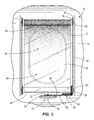
- Figure 1 illustrates a front perspective view of one embodiment of a window shade assembly 10 attached to a structure 12 comprising an aircraft.
- the window shade assembly 10 may be attached to any type of structure such as any type of vehicle or varying structures.
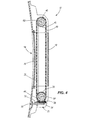
- Figure 2 illustrates a front perspective view of the window shade assembly 10 of Figure 1 removed from the structure 12.
- Figure 3 illustrates a back view of the window shade assembly 10 of Figure 1 attached to the structure 12 with a back window panel removed.
- Figure 4 illustrates a side view of the window assembly 10 of Figure 1 attached to the structure 12.
- the window shade assembly 10 includes: a window 14; an inner pane 16; an outer pane 18; an actuating device 20; and a film 22.
- the inner pane 16 and the outer pane 18 of the window 14 are made of a transparent material such as glass or other transparent materials to allow a person to look through the window 14.
- the actuating device 20 and the film 22 are disposed between the inner pane 16 and the outer pane 18 of the window 14.
- the actuating device 20 is coupled to the film 22 for moving the film 22 within the window 14 between the inner pane 16 and the outer pane 18.
- the film 22 is made of a material, such as transparent plastic film, which gradually transitions from an opaque portion 24, to a translucent portion 26, to a transparent portion 28. In other embodiments, the film 22 may be made of varying materials.
- the term 'opaque' is defined as being in a range of 80% to 100% opacity.
- the term 'translucent' is defined as being in a range of 30% to 80% opacity.
- the translucent portion 26 is gradiated such that its opacity varies from a higher percentage adjacent the opaque portion 24 to a lower percentage adjacent the transparent portion 28. In other embodiments, the gradiation of the translucent portion 26 may vary.
- the term 'transparent' is defined as being in a range of 0% to 30% opacity.
- the ranges may vary.
- the arrangement, configuration, and respective sizes of the opaque portion 24, the translucent portion 26, and the transparent portion 28 may vary, or one or more of the opaque portion 24, the translucent portion 26, or the transparent portion 28 may not be present.
- the film 22 has an ultra-violet resistance in a range of 100 kLy/yr to 1,000 kLy/yr, and a heat resistance in a range of -40 C to 100 C.
- the film 22 is flexible enough to bend in a radius of 0.25 inches to 0.5 inches with no plastic deformation.
- the ranges may vary.
- the actuating device 20 is used to move the film 22 to control whether the opaque portion 24, the translucent portion 26, or the transparent portion 28, or a combination thereof, covers the window 14.
- the opaque portion 24, the translucent portion 26, and the transparent portion 28 of the film 22 are each separately sized to completely cover the window 14 when they are each separately aligned over the window 14. In such manner, when the opaque portion 24 is disposed to completely cover the window 14 the window 14 is opaque. Similarly, when the translucent portion 26 is disposed to completely cover the window 14 the window 14 is translucent. Finally, when the transparent portion 28 is disposed to completely cover the window 14 the window 14 is transparent.
- the size and configurations of the opaque portion 24, the translucent portion 26, and the transparent portion 28 of the film 22 may vary.
- the opaque portion 24, the translucent portion 26, and the transparent portion 28 may gradually transition into each other via a gradient so that a top of the window 14 may be opaque which fades into a translucent bottom half of the window 14.
- the translucent portion 26 may be gradiated such that its opacity varies from a higher percentage adjacent the opaque portion 24 to a lower percentage adjacent the transparent portion 28.
- varying configurations may be utilized.
- the actuating device 20 includes: a control member 30; gears 32, 34, 36, 38, and 40; a first member 44; a second member 46; and a third member 48.
- the control member 30 is used by a person to control movement of the actuating device 20 to mechanically move the film 22 relative to the window 14 without the necessity of a power source.
- the control member 30 is a knob which a passenger may rotate to cause the knob to rotate around or with a first shaft 50. In other embodiments, the control member 30 may be a lever or other type of control member.
- the first gear 32 is concentrically connected to the first shaft 50 so that when the control member 30 is rotated, the first shaft 50 is rotated causing the first gear 32 to rotate.
- the first gear 32 is aligned in parallel arrangement against the second gear 34 to rotate the second gear 34 around or with a second shaft 56.
- the second gear 34 is aligned in parallel arrangement against the third gear 36 to rotate the third gear 36 around or with a third shaft 60.
- the third gear 36 is aligned in perpendicular arrangement against a fourth gear 38 to rotate the fourth gear 38.
- the fourth gear 38 is connected to the first member 44 so that when the fourth gear 38 rotates around or with a fourth shaft 64 the first member 44 also rotates around or with the fourth shaft 64.
- the first member 44 is a roller which is disposed at a bottom of the window 14. In other embodiments, the first member 44 may vary. In still another embodiment, the first member 44 may act as the fourth shaft 64 if the fourth gear 38 is formed with or coupled to the first member 44. In other embodiments, varying configurations may be utilized.
- the third member 48 is coupled between and to the fourth gear 38, which is connected to the first member 44, and the fifth gear 40 connected to the second member 46.
- the third member 48 is a chain, belt, or other type of member.
- the fourth gear 38 rotates around or with the fourth shaft 64, thereby rotating the attached first member 44 around or with the fourth shaft 64
- the coupled third member 48 also rotates thereby rotating the fifth gear 40 and the attached second member 46 around or with a fifth shaft 68.
- the second member 46 is a roller which is disposed at a top of the window 14 apart from the first member 44. In other embodiments, the second member 46 may vary. In still another embodiment, the second member 46 may act as the fifth shaft 68 if the fifth gear 40 is formed with or coupled to the second member 46. In other embodiments, varying configurations may be utilized.
- the film 22 is continuously disposed against, around, and in-between the first member 44 and the second member 46 so that when the first member 44 rotates around or with the fourth shaft 64 and the second member 46 rotates around or with the fifth shaft 68, the film 22 moves around or with the first and second members 44 and 46.
- the control member 30 when a person rotates the control member 30 the person is able to selectively control whether the opaque portion 24, the translucent portion 26, or the transparent portion 28 of the film 22, or a combination thereof, is disposed over the window 14 to selectively control whether the window is opaque, translucent, transparent, or a combination thereof.
- a varying number, type, configuration, alignment, or material may be used for any of the components of the window shade assembly 10.
- FIG. 5 is a flowchart illustrating one embodiment of a method 70 for operating a window shade assembly.
- a film is moved so that a transparent portion of the film covers a section of a window in order to make the section of the window transparent.
- an opaque portion of the film and a translucent portion of the film may be rolled around a second member towards the first member and the transparent portion of the film may be rolled around the first member towards the second member to be disposed between the first and the second members.
- the film is moved so that a translucent portion of the film covers the section of the window in order to make the section of the window translucent.
- the opaque portion of the film may be further rolled towards the first member, the transparent portion of the film may be rolled around the second member, and the translucent portion of the film may be rolled from the first member towards the second member to be disposed between the first and the second members.
- the film is moved so that an opaque portion of the film covers the section of the window in order to make the section of the window opaque.
- the transparent portion of the film and the translucent portion of the film may be rolled around the second member and the opaque portion of the film may be rolled around the first member towards the second member to be disposed between the first and the second members.
- each of steps 72, 74, and 76 may further include moving the film between panes of the window due to a user moving a control member to mechanically move the film using a mechanical actuating device without a power source.
- the window shade assembly and the window may be a portion of an aircraft, vehicle, or other type of structure.
- one or more steps may be modified in substance or in order, or one or more steps may be added depending on the configuration of the film which may vary.
- One or more embodiments of the disclosure may reduce one or more issues of one or more of the existing window shades by: reducing the size needed for the window shade; allowing a user to mechanically control the window shade without a power source; allowing a user to selectively transition the shading of the window between opaque, translucent, and transparent; disposing the window shade away from the user thereby preventing the window shade from become dirty, worn, or damaged; or by containing one or more additional advantages.
Abstract
Description
- This disclosure relates to a window shading assembly which may be used in a wide variety of structures such as in an aircraft, in a vehicle, or in another type of structure to vary the amount of light coming through the window.
- It is often beneficial to be able to selectively alter the amount of light coming through a window in a structure such as in an aircraft or other type of structure. Aircraft typically utilize a plastic shade, contained in a housing, which slides over a window to allow a passenger to control the amount of light coming through the window. However, the housing occupies substantial volume behind the sidewall in the area over the window in order to contain the shade when it is in a lifted position. This housing prevents ducting, wiring, insulation, and other structures from being installed in that area. Moreover, the plastic shade is accessible to the passenger which may lead to the plastic shade becoming dirty, getting worn, or incurring damage. Additionally, this arrangement does not allow the user to gradually transition the amount of light coming through the window as the areas of the window covered by the plastic shade are completely opaque and the areas of the window not covered by the plastic shade are transparent.
- Another type of existing shade includes one roller with a fabric sheet wrapped around the roller. The fabric sheet includes a free end that is configured to be hooked into a closed position. However, this arrangement does not allow the user to gradually transition the amount of light coming through the window, and further allows the user to have access to the fabric sheet which may lead to the fabric sheet becoming dirty, getting worn, or incurring damage. Still other existing window shade systems use electrically-dimmable glass or electrically-operated shutters to allow a user to control the control the amount of light coming through the window. However, these systems require their own power source and electric controls to adjust the opacity of the glass or to control movement of the electrically-operated shutters.
- A window shade is needed to overcome one or more of the issues of one or more of the existing window shades.
- In one embodiment, a window shade assembly includes a first member, a second member, a film, and an actuating device. The second member is disposed apart from the first member. The film has a first end coupled to the first member, a second opposed end coupled to the second member, an opaque portion, and a transparent portion. The actuating device is coupled to the first member or the second member for moving the first member or the second member to move the film between the first and the second members.
- In another embodiment, a window shade assembly includes a window, a film, and an actuating device. The window has an inner pane and an outer pane. The film is disposed between the inner pane and the outer pane of the window, and has an opaque portion and a transparent portion. The actuating device is coupled to the film for moving the film between the inner pane and the outer pane of the window.
- In still another embodiment, a method for operating a window shade assembly is disclosed. In one step, a film is moved so that a transparent portion of the film covers a section of a window in order to make the section of the window transparent to a viewer. In another step, the film is moved so that an opaque portion of the film covers the section of the window in order to make the section of the window opaque to the viewer.
- According to an aspect of the present disclosure there is provided a window shade assembly comprising: a first member; a second member disposed apart from the first member; a film having a first end coupled to the first member and a second opposed end coupled to the second member, the film having an opaque portion and a transparent portion; and an actuating device coupled to the first member or the second member for moving the first member or the second member to move the film between the first and the second members.
- Advantageously the first member and the second member each comprise a roller.
- Advantageously the film transitions from the opaque portion to a translucent portion to the transparent portion with the translucent portion being gradiated such that its opacity varies from a higher percentage adjacent the opaque portion to a lower percentage adjacent the transparent portion.
- Advantageously the actuating device comprises a control member coupled to a chain or belt that is coupled to the first member or the second member. Preferably the control member comprises a knob or lever coupled to a plurality of gears coupled to the chain or belt.
- Advantageously the film continuously wraps around the first member and the second member.
- Advantageously the opaque portion and the transparent portion are each sized to completely cover a viewable section of the window.
- According to a further aspect of the present disclosure there is provided a window shade assembly comprising: a window having an inner pane and an outer pane; a film disposed between the inner pane and the outer pane of the window, the film having an opaque portion and a transparent portion; and an actuating device coupled to the film for moving the film between the inner pane and the outer pane of the window.
- Advantageously the window shade assembly is disposed between an inner wall and an outer wall of an aircraft.
- Advantageously the inner pane and the outer pane are each made of a transparent material.
- Advantageously the window shade assembly further comprises a first member disposed at a bottom of the window and a second member disposed at a top of the window, wherein the film is disposed against and in-between the first member and the second member, and the first member or the second member is configured to move the film between the inner and outer panes of the window. Preferably the first member and the second member each comprise a roller. Preferably the actuating device comprises a control member coupled to a chain or belt that is coupled to the first member or the second member. Preferably the control member comprises a knob or lever, and the actuating device further comprises a plurality of gears coupling the knob or lever to the chain or belt.
- Advantageously the film transitions from the opaque portion to a translucent portion to the transparent portion with the translucent portion being gradiated such that its opacity varies from a higher percentage adjacent the opaque portion to a lower percentage adjacent the transparent portion.
- According to a yet further aspect of the present disclosure there is provided a method for operating a window shade assembly comprising: moving a film so that a transparent portion of the film covers a section of a window in order to make the section of the window transparent to a viewer; and moving the film so that an opaque portion of the film covers the section of the window in order to make the section of the window opaque to the viewer.
- Advantageously the moving the film steps each further comprise moving the film through a passage defined between panes of a window.
- Advantageously the moving the film steps each further comprise manually moving a control member to mechanically move the film using a mechanical actuating device.
- Advantageously the method further comprises moving the film so that a translucent portion of the film covers the section of the window in order to make the section of the window translucent to the viewer.
- Advantageously moving the film further comprises selectively moving the film between a pair of spaced apart rollers.
- The scope of the present disclosure is defined solely by the appended claims and is not affected by the statements within this summary.
- The disclosure can be better understood with reference to the following drawings and description. The components in the figures are not necessarily to scale, emphasis instead being placed upon illustrating the principles of the disclosure.
-
Figure 1 illustrates a front perspective view of one embodiment of a window shade assembly attached to a structure comprising an aircraft; -
Figure 2 illustrates a front perspective view of the window shade assembly ofFigure 1 removed from the structure; -
Figure 3 illustrates a back view of the window shade assembly ofFigure 1 attached to the structure with a back window panel removed; -
Figure 4 illustrates a side view of the window assembly ofFigure 1 attached to the structure; and -
Figure 5 is a flowchart illustrating one embodiment of a method for operating a window shade assembly. -
Figure 1 illustrates a front perspective view of one embodiment of awindow shade assembly 10 attached to astructure 12 comprising an aircraft. In other embodiments, thewindow shade assembly 10 may be attached to any type of structure such as any type of vehicle or varying structures.Figure 2 illustrates a front perspective view of thewindow shade assembly 10 ofFigure 1 removed from thestructure 12.Figure 3 illustrates a back view of thewindow shade assembly 10 ofFigure 1 attached to thestructure 12 with a back window panel removed.Figure 4 illustrates a side view of thewindow assembly 10 ofFigure 1 attached to thestructure 12. - As shown collectively in
Figures 1-4 , thewindow shade assembly 10 includes: awindow 14; aninner pane 16; anouter pane 18; anactuating device 20; and afilm 22. Theinner pane 16 and theouter pane 18 of thewindow 14 are made of a transparent material such as glass or other transparent materials to allow a person to look through thewindow 14. The actuatingdevice 20 and thefilm 22 are disposed between theinner pane 16 and theouter pane 18 of thewindow 14. Theactuating device 20 is coupled to thefilm 22 for moving thefilm 22 within thewindow 14 between theinner pane 16 and theouter pane 18. - The
film 22 is made of a material, such as transparent plastic film, which gradually transitions from anopaque portion 24, to atranslucent portion 26, to atransparent portion 28. In other embodiments, thefilm 22 may be made of varying materials. The term 'opaque' is defined as being in a range of 80% to 100% opacity. The term 'translucent' is defined as being in a range of 30% to 80% opacity. Thetranslucent portion 26 is gradiated such that its opacity varies from a higher percentage adjacent theopaque portion 24 to a lower percentage adjacent thetransparent portion 28. In other embodiments, the gradiation of thetranslucent portion 26 may vary. The term 'transparent' is defined as being in a range of 0% to 30% opacity. In other embodiments, the ranges may vary. In still other embodiments, the arrangement, configuration, and respective sizes of theopaque portion 24, thetranslucent portion 26, and thetransparent portion 28 may vary, or one or more of theopaque portion 24, thetranslucent portion 26, or thetransparent portion 28 may not be present. Thefilm 22 has an ultra-violet resistance in a range of 100 kLy/yr to 1,000 kLy/yr, and a heat resistance in a range of -40 C to 100 C. Thefilm 22 is flexible enough to bend in a radius of 0.25 inches to 0.5 inches with no plastic deformation. In other embodiments, the ranges may vary. - The
actuating device 20 is used to move thefilm 22 to control whether theopaque portion 24, thetranslucent portion 26, or thetransparent portion 28, or a combination thereof, covers thewindow 14. Theopaque portion 24, thetranslucent portion 26, and thetransparent portion 28 of thefilm 22 are each separately sized to completely cover thewindow 14 when they are each separately aligned over thewindow 14. In such manner, when theopaque portion 24 is disposed to completely cover thewindow 14 thewindow 14 is opaque. Similarly, when thetranslucent portion 26 is disposed to completely cover thewindow 14 thewindow 14 is translucent. Finally, when thetransparent portion 28 is disposed to completely cover thewindow 14 thewindow 14 is transparent. In other embodiments, the size and configurations of theopaque portion 24, thetranslucent portion 26, and thetransparent portion 28 of thefilm 22 may vary. For instance, in one embodiment theopaque portion 24, thetranslucent portion 26, and thetransparent portion 28 may gradually transition into each other via a gradient so that a top of thewindow 14 may be opaque which fades into a translucent bottom half of thewindow 14. For instance, thetranslucent portion 26 may be gradiated such that its opacity varies from a higher percentage adjacent theopaque portion 24 to a lower percentage adjacent thetransparent portion 28. In still other embodiments, varying configurations may be utilized. - The
actuating device 20 includes: acontrol member 30; gears 32, 34, 36, 38, and 40; afirst member 44; asecond member 46; and athird member 48. Thecontrol member 30 is used by a person to control movement of theactuating device 20 to mechanically move thefilm 22 relative to thewindow 14 without the necessity of a power source. Thecontrol member 30 is a knob which a passenger may rotate to cause the knob to rotate around or with afirst shaft 50. In other embodiments, thecontrol member 30 may be a lever or other type of control member. - The
first gear 32 is concentrically connected to thefirst shaft 50 so that when thecontrol member 30 is rotated, thefirst shaft 50 is rotated causing thefirst gear 32 to rotate. Thefirst gear 32 is aligned in parallel arrangement against thesecond gear 34 to rotate thesecond gear 34 around or with asecond shaft 56. Thesecond gear 34 is aligned in parallel arrangement against thethird gear 36 to rotate thethird gear 36 around or with athird shaft 60. Thethird gear 36 is aligned in perpendicular arrangement against afourth gear 38 to rotate thefourth gear 38. Thefourth gear 38 is connected to thefirst member 44 so that when thefourth gear 38 rotates around or with afourth shaft 64 thefirst member 44 also rotates around or with thefourth shaft 64. Thefirst member 44 is a roller which is disposed at a bottom of thewindow 14. In other embodiments, thefirst member 44 may vary. In still another embodiment, thefirst member 44 may act as thefourth shaft 64 if thefourth gear 38 is formed with or coupled to thefirst member 44. In other embodiments, varying configurations may be utilized. - The
third member 48 is coupled between and to thefourth gear 38, which is connected to thefirst member 44, and thefifth gear 40 connected to thesecond member 46. Thethird member 48 is a chain, belt, or other type of member. When thefourth gear 38 rotates around or with thefourth shaft 64, thereby rotating the attachedfirst member 44 around or with thefourth shaft 64, the coupledthird member 48 also rotates thereby rotating thefifth gear 40 and the attachedsecond member 46 around or with afifth shaft 68. Thesecond member 46 is a roller which is disposed at a top of thewindow 14 apart from thefirst member 44. In other embodiments, thesecond member 46 may vary. In still another embodiment, thesecond member 46 may act as thefifth shaft 68 if thefifth gear 40 is formed with or coupled to thesecond member 46. In other embodiments, varying configurations may be utilized. - The
film 22 is continuously disposed against, around, and in-between thefirst member 44 and thesecond member 46 so that when thefirst member 44 rotates around or with thefourth shaft 64 and thesecond member 46 rotates around or with thefifth shaft 68, thefilm 22 moves around or with the first andsecond members control member 30 the person is able to selectively control whether theopaque portion 24, thetranslucent portion 26, or thetransparent portion 28 of thefilm 22, or a combination thereof, is disposed over thewindow 14 to selectively control whether the window is opaque, translucent, transparent, or a combination thereof. In other embodiments, a varying number, type, configuration, alignment, or material may be used for any of the components of thewindow shade assembly 10. -
Figure 5 is a flowchart illustrating one embodiment of amethod 70 for operating a window shade assembly. Instep 72, a film is moved so that a transparent portion of the film covers a section of a window in order to make the section of the window transparent. During this step, an opaque portion of the film and a translucent portion of the film may be rolled around a second member towards the first member and the transparent portion of the film may be rolled around the first member towards the second member to be disposed between the first and the second members. Instep 74, the film is moved so that a translucent portion of the film covers the section of the window in order to make the section of the window translucent. During this step, the opaque portion of the film may be further rolled towards the first member, the transparent portion of the film may be rolled around the second member, and the translucent portion of the film may be rolled from the first member towards the second member to be disposed between the first and the second members. Instep 76, the film is moved so that an opaque portion of the film covers the section of the window in order to make the section of the window opaque. During this step, the transparent portion of the film and the translucent portion of the film may be rolled around the second member and the opaque portion of the film may be rolled around the first member towards the second member to be disposed between the first and the second members. In one embodiment, each ofsteps - One or more embodiments of the disclosure may reduce one or more issues of one or more of the existing window shades by: reducing the size needed for the window shade; allowing a user to mechanically control the window shade without a power source; allowing a user to selectively transition the shading of the window between opaque, translucent, and transparent; disposing the window shade away from the user thereby preventing the window shade from become dirty, worn, or damaged; or by containing one or more additional advantages.
- The Abstract is provided to allow the reader to quickly ascertain the nature of the technical disclosure. It is submitted with the understanding that it will not be used to interpret or limit the scope or meaning of the claims. In addition, in the foregoing Detailed Description, it can be seen that various features are grouped together in various embodiments for the purpose of streamlining the disclosure. This method of disclosure is not to be interpreted as reflecting an intention that the claimed embodiments require more features than are expressly recited in each claim. Rather, as the following claims reflect, inventive subject matter lies in less than all features of a single disclosed embodiment. Thus the following claims are hereby incorporated into the Detailed Description, with each claim standing on its own as a separately claimed subject matter.
- While particular aspects of the present subject matter described herein have been shown and described, it will be apparent to those skilled in the art that, based upon the teachings herein, changes and modifications may be made without departing from the subject matter described herein and its broader aspects and, therefore, the appended claims are to encompass within their scope all such changes and modifications as are within the true spirit and scope of the subject matter described herein. Furthermore, it is to be understood that the disclosure is defined by the appended claims. Accordingly, the disclosure is not to be restricted except in light of the appended claims and their equivalents.
Claims (15)
- A window shade assembly (10) comprising:a first member (44);a second member (46) disposed apart from the first member;a film (22) having a first end coupled to the first member and a second opposed end coupled to the second member, the film having an opaque portion (24) and a transparent portion (28); andan actuating device (20) coupled to the first member or the second member for moving the first member or the second member to move the film between the first and the second members.
- The window shade assembly (10) of claim 1 wherein the first member (44) and the second member (46) each comprise a roller.
- The window shade assembly (10) of claim 1 or 2 wherein the film (22) transitions from the opaque portion (24) to a translucent portion (26) to the transparent portion (28) with the translucent portion being gradiated such that its opacity varies from a higher percentage adjacent the opaque portion to a lower percentage adjacent the transparent portion.
- The window shade assembly (10) of any preceding claim wherein the actuating device (20) comprises a control member (30) coupled to a chain or belt that is coupled to the first member (44) or the second member (46).
- The window shade assembly (10) of claim 4 wherein the control member (30) comprises a knob or lever coupled to a plurality of gears (32, 34, 36, 38, 40) coupled to the chain or belt.
- The window shade assembly (10) of any preceding claim wherein the film (22) continuously wraps around the first member (44) and the second member (46).
- The window shade assembly (10) of any preceding claim wherein the opaque portion (24) and the transparent portion (28) are each sized to completely cover a viewable section of a window (14).
- The window shade assembly (10) of any preceding claim further comprising a window (14) having an inner pane (16) and an outer pane (18), wherein the film (22) is disposed between the inner pane and the outer pane of the window, and the actuating device (20) is coupled to the film for moving the film between the inner pane and the outer pane of the window.
- The window shade assembly (10) of claim 8 wherein the window shade assembly is disposed between an inner wall and an outer wall of an aircraft.
- The window shade assembly (10) of claim 8 or 9 wherein the first member (44) is disposed at a bottom of the window (14) and the second member (46) is disposed at a top of the window, wherein the film is disposed against and in-between the first member and the second member, and the first member or the second member is configured to move the film between the inner and outer panes of the window.
- A method (70) for operating a window shade assembly (10), the method comprising:moving (72) a film (22) so that a transparent portion (28) of the film covers a section of a window (14) in order to make the section of the window transparent to a viewer; andmoving (76) the film so that an opaque portion (24) of the film covers the section of the window in order to make the section of the window opaque to the viewer.
- The method (70) of claim 11 wherein the moving (72, 76) the film (22) steps each further comprise moving the film through a passage defined between panes (16, 18) of the window (14).
- The method (70) of claim 11 or 12 wherein the moving (72, 76) the film (22) steps each further comprise manually moving a control member (20) to mechanically move the film using a mechanical actuating device.
- The method (70) of any of claims 11-13 further comprising moving (74) the film (22) so that a translucent portion (26) of the film covers the section of the window (14) in order to make the section of the window translucent to the viewer.
- The method (70) of any of claims 11-14 wherein moving (72, 74, 76) the film (22) further comprises selectively moving the film between a pair of spaced apart rollers.
Applications Claiming Priority (1)
| Application Number | Priority Date | Filing Date | Title |
|---|---|---|---|
| US13/752,669 US20140209746A1 (en) | 2013-01-29 | 2013-01-29 | Window shading assembly |
Publications (3)
| Publication Number | Publication Date |
|---|---|
| EP2759426A2 true EP2759426A2 (en) | 2014-07-30 |
| EP2759426A3 EP2759426A3 (en) | 2016-07-27 |
| EP2759426B1 EP2759426B1 (en) | 2021-02-03 |
Family
ID=49753022
Family Applications (1)
| Application Number | Title | Priority Date | Filing Date |
|---|---|---|---|
| EP13196235.9A Active EP2759426B1 (en) | 2013-01-29 | 2013-12-09 | Window shading assembly |
Country Status (5)
| Country | Link |
|---|---|
| US (1) | US20140209746A1 (en) |
| EP (1) | EP2759426B1 (en) |
| BR (1) | BR102014001592B1 (en) |
| CA (1) | CA2829648C (en) |
| ES (1) | ES2864775T3 (en) |
Cited By (1)
| Publication number | Priority date | Publication date | Assignee | Title |
|---|---|---|---|---|
| CN105064883A (en) * | 2015-09-02 | 2015-11-18 | 天津市日月门窗有限公司 | Window with function of writing board |
Families Citing this family (10)
| Publication number | Priority date | Publication date | Assignee | Title |
|---|---|---|---|---|
| US9592902B2 (en) * | 2014-02-17 | 2017-03-14 | The Boeing Company | Hatch assembly for use in a vehicle and method of assembling the same |
| US20170321481A1 (en) * | 2015-02-12 | 2017-11-09 | Sina Ashkanmehr | Light adjustment system for a window |
| US10214958B2 (en) * | 2016-12-14 | 2019-02-26 | Hall Labs Llc | Customizable glass wall system |
| US10533372B2 (en) * | 2017-03-13 | 2020-01-14 | Textron Innovations, Inc. | Aircraft window shade |
| US10676990B2 (en) * | 2017-09-19 | 2020-06-09 | Thomas L Delvecchio | Motorized window shades for RVs |
| CN108638809B (en) * | 2018-07-10 | 2020-10-27 | 安徽合众智信科技咨询有限公司 | Adjustable hidden sunshade plate structure for automobile |
| ES1217284Y (en) * | 2018-07-20 | 2018-12-05 | Sanchez Chas Marcos | CONFIGURABLE OUTDOOR ASPECT WINDOW |
| US10988970B2 (en) | 2018-09-19 | 2021-04-27 | The Boeing Company | Window assembly for use in a vehicle |
| US11059560B2 (en) | 2018-09-19 | 2021-07-13 | The Boeing Company | Window assembly for use in a vehicle |
| CN110374481B (en) * | 2019-07-30 | 2020-06-26 | 开县金石教育服务有限责任公司 | Self-color-changing window and indoor environment adjusting system thereof |
Family Cites Families (20)
| Publication number | Priority date | Publication date | Assignee | Title |
|---|---|---|---|---|
| DE3782635T2 (en) * | 1986-12-29 | 1993-03-25 | Ted N Magee | CARTRIDGE CURTAIN STRUCTURE. |
| US6186211B1 (en) * | 1999-02-22 | 2001-02-13 | Aerospace Technologies Group, Inc. | Window assembly with a motorized window shade mechanism |
| US6481486B1 (en) * | 2000-02-08 | 2002-11-19 | Msa Aircraft Products, Ltd. | Modular aircraft window with a dual shade |
| US6832641B1 (en) * | 1999-11-17 | 2004-12-21 | Eduardo Sanz | Electric dual shade aircraft window |
| DE19960032A1 (en) * | 1999-12-13 | 2001-07-05 | Erik Salatsch | House blind for window coverage varies in tranparency right along blind length itself longer than served window or with sectors of varied transparency along blind. |
| US6460805B1 (en) * | 2000-08-24 | 2002-10-08 | Msa Aircraft Products, Ltd. | Double convex aircraft window |
| US6915988B2 (en) * | 2003-01-27 | 2005-07-12 | Msa Aircraft Products, Ltd. | Matrix window |
| US20050263254A1 (en) * | 2004-05-27 | 2005-12-01 | Sievers Thomas J | Window shade positioning apparatus and method |
| US7510146B2 (en) * | 2004-09-23 | 2009-03-31 | Robert Golden | Window shade system and method of use |
| US7264034B2 (en) * | 2005-01-25 | 2007-09-04 | Ke-Min Lin | Motorized blind |
| US20090277593A1 (en) * | 2008-05-09 | 2009-11-12 | Stewart Grant W | Acoustic window shade |
| US7690414B2 (en) * | 2006-12-26 | 2010-04-06 | Aerospace Technologies Group, Inc. | Motorized window shade |
| DE102007006540B4 (en) * | 2007-02-09 | 2012-11-22 | Airbus Operations Gmbh | Aircraft window darkening system |
| US20090283227A1 (en) * | 2008-05-13 | 2009-11-19 | Msa Aircraft Products Ltd. | Clutch operated electric aircraft window with manual override |
| US20090241424A1 (en) * | 2008-06-06 | 2009-10-01 | Msa Aircraft Products Ltd. | Modular Window For An Aircraft Including An SPD Lens And An Opaque Shade |
| US20090314439A1 (en) * | 2008-06-18 | 2009-12-24 | Steve Waters | Window shade |
| US9045215B2 (en) * | 2009-11-11 | 2015-06-02 | Aerospace Technologies Group, Inc. | Window assembly with a motorized window shade mechanism |
| US20120067528A1 (en) * | 2010-09-16 | 2012-03-22 | Mohat Nicholas C | Lead screw driven chain drive modular manually operated window shade system for an aircraft |
| US8944381B2 (en) * | 2011-03-25 | 2015-02-03 | The Boeing Company | Aircraft window and installation method |
| US8919418B2 (en) * | 2011-12-01 | 2014-12-30 | Maria Paulina Carvallo | Curtain system |
-
2013
- 2013-01-29 US US13/752,669 patent/US20140209746A1/en not_active Abandoned
- 2013-10-08 CA CA2829648A patent/CA2829648C/en active Active
- 2013-12-09 ES ES13196235T patent/ES2864775T3/en active Active
- 2013-12-09 EP EP13196235.9A patent/EP2759426B1/en active Active
-
2014
- 2014-01-23 BR BR102014001592-2A patent/BR102014001592B1/en active IP Right Grant
Non-Patent Citations (1)
| Title |
|---|
| None |
Cited By (1)
| Publication number | Priority date | Publication date | Assignee | Title |
|---|---|---|---|---|
| CN105064883A (en) * | 2015-09-02 | 2015-11-18 | 天津市日月门窗有限公司 | Window with function of writing board |
Also Published As
| Publication number | Publication date |
|---|---|
| BR102014001592B1 (en) | 2022-02-15 |
| ES2864775T3 (en) | 2021-10-14 |
| US20140209746A1 (en) | 2014-07-31 |
| EP2759426B1 (en) | 2021-02-03 |
| BR102014001592A2 (en) | 2014-11-25 |
| CA2829648A1 (en) | 2014-07-29 |
| CA2829648C (en) | 2017-06-06 |
| EP2759426A3 (en) | 2016-07-27 |
Similar Documents
| Publication | Publication Date | Title |
|---|---|---|
| EP2759426A2 (en) | Window shading assembly | |
| EP2596196B1 (en) | Dual roll blind | |
| US11499367B2 (en) | Light-redirecting window covering | |
| US8690235B2 (en) | Device for operating sunroof in vehicle | |
| WO2014189061A1 (en) | Light control tool | |
| US20090241424A1 (en) | Modular Window For An Aircraft Including An SPD Lens And An Opaque Shade | |
| US8146646B1 (en) | System and method for controlling multiple window coverings using a single manually manipulated control | |
| CN201198729Y (en) | Built-in sun-shading hollow shutter | |
| DE102005036348A1 (en) | Median facade for e.g. multistory building, has window shades made of sheet materials, which are extendible from bottom up or from top down or from sides and are impingeable with light images by light projectors from inside and/or outside | |
| US20170321481A1 (en) | Light adjustment system for a window | |
| US20160168905A1 (en) | Multi-stage sunshade device | |
| KR102362780B1 (en) | Slat having high reflectance, manufacturing methed thereof and blind apparatus having that | |
| JP5427732B2 (en) | Blind device for vehicle | |
| CN203081134U (en) | Window capable of being automatically opened and closed | |
| CN101131065A (en) | Lighting-adjustable window | |
| US10801260B2 (en) | Motorized window covering having powered modules | |
| JPS61287814A (en) | Shielding device for car window | |
| KR200448353Y1 (en) | Three dimensions cuttern sheet of open and close device | |
| JP2007092350A (en) | Louver device | |
| JP5957285B2 (en) | Visible light transparent blind and its use | |
| JP2012224975A (en) | Rolling screen | |
| DE3247970A1 (en) | Sheet-type roller blind for the air-conditioning of buildings | |
| CN2680827Y (en) | Interlayer movable double layer glass window | |
| KR200472606Y1 (en) | Blind | |
| CN202431165U (en) | Internal awning window |
Legal Events
| Date | Code | Title | Description |
|---|---|---|---|
| PUAI | Public reference made under article 153(3) epc to a published international application that has entered the european phase |
Free format text: ORIGINAL CODE: 0009012 |
|
| 17P | Request for examination filed |
Effective date: 20131209 |
|
| AK | Designated contracting states |
Kind code of ref document: A2 Designated state(s): AL AT BE BG CH CY CZ DE DK EE ES FI FR GB GR HR HU IE IS IT LI LT LU LV MC MK MT NL NO PL PT RO RS SE SI SK SM TR |
|
| AX | Request for extension of the european patent |
Extension state: BA ME |
|
| PUAL | Search report despatched |
Free format text: ORIGINAL CODE: 0009013 |
|
| AK | Designated contracting states |
Kind code of ref document: A3 Designated state(s): AL AT BE BG CH CY CZ DE DK EE ES FI FR GB GR HR HU IE IS IT LI LT LU LV MC MK MT NL NO PL PT RO RS SE SI SK SM TR |
|
| AX | Request for extension of the european patent |
Extension state: BA ME |
|
| RIC1 | Information provided on ipc code assigned before grant |
Ipc: B64C 1/14 20060101ALI20160621BHEP Ipc: E06B 9/40 20060101ALI20160621BHEP Ipc: B60J 1/20 20060101AFI20160621BHEP Ipc: E06B 9/24 20060101ALI20160621BHEP |
|
| STAA | Information on the status of an ep patent application or granted ep patent |
Free format text: STATUS: REQUEST FOR EXAMINATION WAS MADE |
|
| R17P | Request for examination filed (corrected) |
Effective date: 20170117 |
|
| RBV | Designated contracting states (corrected) |
Designated state(s): AL AT BE BG CH CY CZ DE DK EE ES FI FR GB GR HR HU IE IS IT LI LT LU LV MC MK MT NL NO PL PT RO RS SE SI SK SM TR |
|
| STAA | Information on the status of an ep patent application or granted ep patent |
Free format text: STATUS: EXAMINATION IS IN PROGRESS |
|
| 17Q | First examination report despatched |
Effective date: 20190902 |
|
| GRAP | Despatch of communication of intention to grant a patent |
Free format text: ORIGINAL CODE: EPIDOSNIGR1 |
|
| STAA | Information on the status of an ep patent application or granted ep patent |
Free format text: STATUS: GRANT OF PATENT IS INTENDED |
|
| INTG | Intention to grant announced |
Effective date: 20200305 |
|
| RIN1 | Information on inventor provided before grant (corrected) |
Inventor name: DUNN, BRANDON W. |
|
| GRAJ | Information related to disapproval of communication of intention to grant by the applicant or resumption of examination proceedings by the epo deleted |
Free format text: ORIGINAL CODE: EPIDOSDIGR1 |
|
| STAA | Information on the status of an ep patent application or granted ep patent |
Free format text: STATUS: EXAMINATION IS IN PROGRESS |
|
| GRAP | Despatch of communication of intention to grant a patent |
Free format text: ORIGINAL CODE: EPIDOSNIGR1 |
|
| STAA | Information on the status of an ep patent application or granted ep patent |
Free format text: STATUS: GRANT OF PATENT IS INTENDED |
|
| INTC | Intention to grant announced (deleted) | ||
| INTG | Intention to grant announced |
Effective date: 20200814 |
|
| GRAS | Grant fee paid |
Free format text: ORIGINAL CODE: EPIDOSNIGR3 |
|
| GRAA | (expected) grant |
Free format text: ORIGINAL CODE: 0009210 |
|
| STAA | Information on the status of an ep patent application or granted ep patent |
Free format text: STATUS: THE PATENT HAS BEEN GRANTED |
|
| AK | Designated contracting states |
Kind code of ref document: B1 Designated state(s): AL AT BE BG CH CY CZ DE DK EE ES FI FR GB GR HR HU IE IS IT LI LT LU LV MC MK MT NL NO PL PT RO RS SE SI SK SM TR |
|
| REG | Reference to a national code |
Ref country code: GB Ref legal event code: FG4D |
|
| REG | Reference to a national code |
Ref country code: AT Ref legal event code: REF Ref document number: 1359627 Country of ref document: AT Kind code of ref document: T Effective date: 20210215 Ref country code: CH Ref legal event code: EP |
|
| REG | Reference to a national code |
Ref country code: DE Ref legal event code: R096 Ref document number: 602013075570 Country of ref document: DE |
|
| REG | Reference to a national code |
Ref country code: IE Ref legal event code: FG4D |
|
| REG | Reference to a national code |
Ref country code: NL Ref legal event code: MP Effective date: 20210203 |
|
| REG | Reference to a national code |
Ref country code: LT Ref legal event code: MG9D |
|
| REG | Reference to a national code |
Ref country code: AT Ref legal event code: MK05 Ref document number: 1359627 Country of ref document: AT Kind code of ref document: T Effective date: 20210203 |
|
| PG25 | Lapsed in a contracting state [announced via postgrant information from national office to epo] |
Ref country code: NO Free format text: LAPSE BECAUSE OF FAILURE TO SUBMIT A TRANSLATION OF THE DESCRIPTION OR TO PAY THE FEE WITHIN THE PRESCRIBED TIME-LIMIT Effective date: 20210503 Ref country code: BG Free format text: LAPSE BECAUSE OF FAILURE TO SUBMIT A TRANSLATION OF THE DESCRIPTION OR TO PAY THE FEE WITHIN THE PRESCRIBED TIME-LIMIT Effective date: 20210503 Ref country code: GR Free format text: LAPSE BECAUSE OF FAILURE TO SUBMIT A TRANSLATION OF THE DESCRIPTION OR TO PAY THE FEE WITHIN THE PRESCRIBED TIME-LIMIT Effective date: 20210504 Ref country code: HR Free format text: LAPSE BECAUSE OF FAILURE TO SUBMIT A TRANSLATION OF THE DESCRIPTION OR TO PAY THE FEE WITHIN THE PRESCRIBED TIME-LIMIT Effective date: 20210203 Ref country code: FI Free format text: LAPSE BECAUSE OF FAILURE TO SUBMIT A TRANSLATION OF THE DESCRIPTION OR TO PAY THE FEE WITHIN THE PRESCRIBED TIME-LIMIT Effective date: 20210203 Ref country code: LT Free format text: LAPSE BECAUSE OF FAILURE TO SUBMIT A TRANSLATION OF THE DESCRIPTION OR TO PAY THE FEE WITHIN THE PRESCRIBED TIME-LIMIT Effective date: 20210203 Ref country code: PT Free format text: LAPSE BECAUSE OF FAILURE TO SUBMIT A TRANSLATION OF THE DESCRIPTION OR TO PAY THE FEE WITHIN THE PRESCRIBED TIME-LIMIT Effective date: 20210604 |
|
| PG25 | Lapsed in a contracting state [announced via postgrant information from national office to epo] |
Ref country code: SE Free format text: LAPSE BECAUSE OF FAILURE TO SUBMIT A TRANSLATION OF THE DESCRIPTION OR TO PAY THE FEE WITHIN THE PRESCRIBED TIME-LIMIT Effective date: 20210203 Ref country code: RS Free format text: LAPSE BECAUSE OF FAILURE TO SUBMIT A TRANSLATION OF THE DESCRIPTION OR TO PAY THE FEE WITHIN THE PRESCRIBED TIME-LIMIT Effective date: 20210203 Ref country code: PL Free format text: LAPSE BECAUSE OF FAILURE TO SUBMIT A TRANSLATION OF THE DESCRIPTION OR TO PAY THE FEE WITHIN THE PRESCRIBED TIME-LIMIT Effective date: 20210203 Ref country code: LV Free format text: LAPSE BECAUSE OF FAILURE TO SUBMIT A TRANSLATION OF THE DESCRIPTION OR TO PAY THE FEE WITHIN THE PRESCRIBED TIME-LIMIT Effective date: 20210203 Ref country code: NL Free format text: LAPSE BECAUSE OF FAILURE TO SUBMIT A TRANSLATION OF THE DESCRIPTION OR TO PAY THE FEE WITHIN THE PRESCRIBED TIME-LIMIT Effective date: 20210203 Ref country code: AT Free format text: LAPSE BECAUSE OF FAILURE TO SUBMIT A TRANSLATION OF THE DESCRIPTION OR TO PAY THE FEE WITHIN THE PRESCRIBED TIME-LIMIT Effective date: 20210203 |
|
| PG25 | Lapsed in a contracting state [announced via postgrant information from national office to epo] |
Ref country code: IS Free format text: LAPSE BECAUSE OF FAILURE TO SUBMIT A TRANSLATION OF THE DESCRIPTION OR TO PAY THE FEE WITHIN THE PRESCRIBED TIME-LIMIT Effective date: 20210603 |
|
| REG | Reference to a national code |
Ref country code: ES Ref legal event code: FG2A Ref document number: 2864775 Country of ref document: ES Kind code of ref document: T3 Effective date: 20211014 |
|
| PG25 | Lapsed in a contracting state [announced via postgrant information from national office to epo] |
Ref country code: EE Free format text: LAPSE BECAUSE OF FAILURE TO SUBMIT A TRANSLATION OF THE DESCRIPTION OR TO PAY THE FEE WITHIN THE PRESCRIBED TIME-LIMIT Effective date: 20210203 Ref country code: CZ Free format text: LAPSE BECAUSE OF FAILURE TO SUBMIT A TRANSLATION OF THE DESCRIPTION OR TO PAY THE FEE WITHIN THE PRESCRIBED TIME-LIMIT Effective date: 20210203 Ref country code: SM Free format text: LAPSE BECAUSE OF FAILURE TO SUBMIT A TRANSLATION OF THE DESCRIPTION OR TO PAY THE FEE WITHIN THE PRESCRIBED TIME-LIMIT Effective date: 20210203 |
|
| REG | Reference to a national code |
Ref country code: DE Ref legal event code: R097 Ref document number: 602013075570 Country of ref document: DE |
|
| PG25 | Lapsed in a contracting state [announced via postgrant information from national office to epo] |
Ref country code: RO Free format text: LAPSE BECAUSE OF FAILURE TO SUBMIT A TRANSLATION OF THE DESCRIPTION OR TO PAY THE FEE WITHIN THE PRESCRIBED TIME-LIMIT Effective date: 20210203 Ref country code: SK Free format text: LAPSE BECAUSE OF FAILURE TO SUBMIT A TRANSLATION OF THE DESCRIPTION OR TO PAY THE FEE WITHIN THE PRESCRIBED TIME-LIMIT Effective date: 20210203 Ref country code: DK Free format text: LAPSE BECAUSE OF FAILURE TO SUBMIT A TRANSLATION OF THE DESCRIPTION OR TO PAY THE FEE WITHIN THE PRESCRIBED TIME-LIMIT Effective date: 20210203 |
|
| PLBE | No opposition filed within time limit |
Free format text: ORIGINAL CODE: 0009261 |
|
| STAA | Information on the status of an ep patent application or granted ep patent |
Free format text: STATUS: NO OPPOSITION FILED WITHIN TIME LIMIT |
|
| 26N | No opposition filed |
Effective date: 20211104 |
|
| PG25 | Lapsed in a contracting state [announced via postgrant information from national office to epo] |
Ref country code: AL Free format text: LAPSE BECAUSE OF FAILURE TO SUBMIT A TRANSLATION OF THE DESCRIPTION OR TO PAY THE FEE WITHIN THE PRESCRIBED TIME-LIMIT Effective date: 20210203 |
|
| PG25 | Lapsed in a contracting state [announced via postgrant information from national office to epo] |
Ref country code: SI Free format text: LAPSE BECAUSE OF FAILURE TO SUBMIT A TRANSLATION OF THE DESCRIPTION OR TO PAY THE FEE WITHIN THE PRESCRIBED TIME-LIMIT Effective date: 20210203 |
|
| PG25 | Lapsed in a contracting state [announced via postgrant information from national office to epo] |
Ref country code: IT Free format text: LAPSE BECAUSE OF FAILURE TO SUBMIT A TRANSLATION OF THE DESCRIPTION OR TO PAY THE FEE WITHIN THE PRESCRIBED TIME-LIMIT Effective date: 20210203 |
|
| PG25 | Lapsed in a contracting state [announced via postgrant information from national office to epo] |
Ref country code: IS Free format text: LAPSE BECAUSE OF FAILURE TO SUBMIT A TRANSLATION OF THE DESCRIPTION OR TO PAY THE FEE WITHIN THE PRESCRIBED TIME-LIMIT Effective date: 20210603 |
|
| PG25 | Lapsed in a contracting state [announced via postgrant information from national office to epo] |
Ref country code: MC Free format text: LAPSE BECAUSE OF FAILURE TO SUBMIT A TRANSLATION OF THE DESCRIPTION OR TO PAY THE FEE WITHIN THE PRESCRIBED TIME-LIMIT Effective date: 20210203 |
|
| REG | Reference to a national code |
Ref country code: CH Ref legal event code: PL |
|
| REG | Reference to a national code |
Ref country code: BE Ref legal event code: MM Effective date: 20211231 |
|
| PG25 | Lapsed in a contracting state [announced via postgrant information from national office to epo] |
Ref country code: LU Free format text: LAPSE BECAUSE OF NON-PAYMENT OF DUE FEES Effective date: 20211209 Ref country code: IE Free format text: LAPSE BECAUSE OF NON-PAYMENT OF DUE FEES Effective date: 20211209 |
|
| PG25 | Lapsed in a contracting state [announced via postgrant information from national office to epo] |
Ref country code: BE Free format text: LAPSE BECAUSE OF NON-PAYMENT OF DUE FEES Effective date: 20211231 |
|
| PG25 | Lapsed in a contracting state [announced via postgrant information from national office to epo] |
Ref country code: LI Free format text: LAPSE BECAUSE OF NON-PAYMENT OF DUE FEES Effective date: 20211231 Ref country code: CH Free format text: LAPSE BECAUSE OF NON-PAYMENT OF DUE FEES Effective date: 20211231 |
|
| PGFP | Annual fee paid to national office [announced via postgrant information from national office to epo] |
Ref country code: ES Payment date: 20230102 Year of fee payment: 10 |
|
| PG25 | Lapsed in a contracting state [announced via postgrant information from national office to epo] |
Ref country code: HU Free format text: LAPSE BECAUSE OF FAILURE TO SUBMIT A TRANSLATION OF THE DESCRIPTION OR TO PAY THE FEE WITHIN THE PRESCRIBED TIME-LIMIT; INVALID AB INITIO Effective date: 20131209 |
|
| PGFP | Annual fee paid to national office [announced via postgrant information from national office to epo] |
Ref country code: DE Payment date: 20221228 Year of fee payment: 10 |
|
| P01 | Opt-out of the competence of the unified patent court (upc) registered |
Effective date: 20230516 |
|
| PG25 | Lapsed in a contracting state [announced via postgrant information from national office to epo] |
Ref country code: CY Free format text: LAPSE BECAUSE OF FAILURE TO SUBMIT A TRANSLATION OF THE DESCRIPTION OR TO PAY THE FEE WITHIN THE PRESCRIBED TIME-LIMIT Effective date: 20210203 |
|
| PGFP | Annual fee paid to national office [announced via postgrant information from national office to epo] |
Ref country code: GB Payment date: 20231227 Year of fee payment: 11 |
|
| PGFP | Annual fee paid to national office [announced via postgrant information from national office to epo] |
Ref country code: FR Payment date: 20231227 Year of fee payment: 11 |
|
| PGFP | Annual fee paid to national office [announced via postgrant information from national office to epo] |
Ref country code: ES Payment date: 20240102 Year of fee payment: 11 |