EP2759329B1 - Method and device for purifying exhaust gases - Google Patents
Method and device for purifying exhaust gases Download PDFInfo
- Publication number
- EP2759329B1 EP2759329B1 EP14000329.4A EP14000329A EP2759329B1 EP 2759329 B1 EP2759329 B1 EP 2759329B1 EP 14000329 A EP14000329 A EP 14000329A EP 2759329 B1 EP2759329 B1 EP 2759329B1
- Authority
- EP
- European Patent Office
- Prior art keywords
- regenerator
- combustion chamber
- catalyst
- regenerators
- waste gas
- Prior art date
- Legal status (The legal status is an assumption and is not a legal conclusion. Google has not performed a legal analysis and makes no representation as to the accuracy of the status listed.)
- Active
Links
Images


Classifications
-
- B—PERFORMING OPERATIONS; TRANSPORTING
- B01—PHYSICAL OR CHEMICAL PROCESSES OR APPARATUS IN GENERAL
- B01D—SEPARATION
- B01D53/00—Separation of gases or vapours; Recovering vapours of volatile solvents from gases; Chemical or biological purification of waste gases, e.g. engine exhaust gases, smoke, fumes, flue gases, aerosols
- B01D53/34—Chemical or biological purification of waste gases
- B01D53/74—General processes for purification of waste gases; Apparatus or devices specially adapted therefor
- B01D53/86—Catalytic processes
- B01D53/869—Multiple step processes
-
- B—PERFORMING OPERATIONS; TRANSPORTING
- B01—PHYSICAL OR CHEMICAL PROCESSES OR APPARATUS IN GENERAL
- B01D—SEPARATION
- B01D53/00—Separation of gases or vapours; Recovering vapours of volatile solvents from gases; Chemical or biological purification of waste gases, e.g. engine exhaust gases, smoke, fumes, flue gases, aerosols
- B01D53/34—Chemical or biological purification of waste gases
- B01D53/343—Heat recovery
-
- B—PERFORMING OPERATIONS; TRANSPORTING
- B01—PHYSICAL OR CHEMICAL PROCESSES OR APPARATUS IN GENERAL
- B01D—SEPARATION
- B01D53/00—Separation of gases or vapours; Recovering vapours of volatile solvents from gases; Chemical or biological purification of waste gases, e.g. engine exhaust gases, smoke, fumes, flue gases, aerosols
- B01D53/34—Chemical or biological purification of waste gases
- B01D53/38—Removing components of undefined structure
-
- B—PERFORMING OPERATIONS; TRANSPORTING
- B01—PHYSICAL OR CHEMICAL PROCESSES OR APPARATUS IN GENERAL
- B01D—SEPARATION
- B01D53/00—Separation of gases or vapours; Recovering vapours of volatile solvents from gases; Chemical or biological purification of waste gases, e.g. engine exhaust gases, smoke, fumes, flue gases, aerosols
- B01D53/34—Chemical or biological purification of waste gases
- B01D53/74—General processes for purification of waste gases; Apparatus or devices specially adapted therefor
- B01D53/86—Catalytic processes
- B01D53/8621—Removing nitrogen compounds
- B01D53/8625—Nitrogen oxides
-
- F—MECHANICAL ENGINEERING; LIGHTING; HEATING; WEAPONS; BLASTING
- F01—MACHINES OR ENGINES IN GENERAL; ENGINE PLANTS IN GENERAL; STEAM ENGINES
- F01N—GAS-FLOW SILENCERS OR EXHAUST APPARATUS FOR MACHINES OR ENGINES IN GENERAL; GAS-FLOW SILENCERS OR EXHAUST APPARATUS FOR INTERNAL COMBUSTION ENGINES
- F01N3/00—Exhaust or silencing apparatus having means for purifying, rendering innocuous, or otherwise treating exhaust
- F01N3/08—Exhaust or silencing apparatus having means for purifying, rendering innocuous, or otherwise treating exhaust for rendering innocuous
- F01N3/10—Exhaust or silencing apparatus having means for purifying, rendering innocuous, or otherwise treating exhaust for rendering innocuous by thermal or catalytic conversion of noxious components of exhaust
- F01N3/18—Exhaust or silencing apparatus having means for purifying, rendering innocuous, or otherwise treating exhaust for rendering innocuous by thermal or catalytic conversion of noxious components of exhaust characterised by methods of operation; Control
- F01N3/20—Exhaust or silencing apparatus having means for purifying, rendering innocuous, or otherwise treating exhaust for rendering innocuous by thermal or catalytic conversion of noxious components of exhaust characterised by methods of operation; Control specially adapted for catalytic conversion ; Methods of operation or control of catalytic converters
- F01N3/2066—Selective catalytic reduction [SCR]
-
- F—MECHANICAL ENGINEERING; LIGHTING; HEATING; WEAPONS; BLASTING
- F23—COMBUSTION APPARATUS; COMBUSTION PROCESSES
- F23G—CREMATION FURNACES; CONSUMING WASTE PRODUCTS BY COMBUSTION
- F23G7/00—Incinerators or other apparatus for consuming industrial waste, e.g. chemicals
- F23G7/06—Incinerators or other apparatus for consuming industrial waste, e.g. chemicals of waste gases or noxious gases, e.g. exhaust gases
- F23G7/061—Incinerators or other apparatus for consuming industrial waste, e.g. chemicals of waste gases or noxious gases, e.g. exhaust gases with supplementary heating
- F23G7/065—Incinerators or other apparatus for consuming industrial waste, e.g. chemicals of waste gases or noxious gases, e.g. exhaust gases with supplementary heating using gaseous or liquid fuel
- F23G7/066—Incinerators or other apparatus for consuming industrial waste, e.g. chemicals of waste gases or noxious gases, e.g. exhaust gases with supplementary heating using gaseous or liquid fuel preheating the waste gas by the heat of the combustion, e.g. recuperation type incinerator
- F23G7/068—Incinerators or other apparatus for consuming industrial waste, e.g. chemicals of waste gases or noxious gases, e.g. exhaust gases with supplementary heating using gaseous or liquid fuel preheating the waste gas by the heat of the combustion, e.g. recuperation type incinerator using regenerative heat recovery means
-
- F—MECHANICAL ENGINEERING; LIGHTING; HEATING; WEAPONS; BLASTING
- F28—HEAT EXCHANGE IN GENERAL
- F28D—HEAT-EXCHANGE APPARATUS, NOT PROVIDED FOR IN ANOTHER SUBCLASS, IN WHICH THE HEAT-EXCHANGE MEDIA DO NOT COME INTO DIRECT CONTACT
- F28D17/00—Regenerative heat-exchange apparatus in which a stationary intermediate heat-transfer medium or body is contacted successively by each heat-exchange medium, e.g. using granular particles
-
- B—PERFORMING OPERATIONS; TRANSPORTING
- B01—PHYSICAL OR CHEMICAL PROCESSES OR APPARATUS IN GENERAL
- B01D—SEPARATION
- B01D2251/00—Reactants
- B01D2251/20—Reductants
- B01D2251/206—Ammonium compounds
-
- B—PERFORMING OPERATIONS; TRANSPORTING
- B01—PHYSICAL OR CHEMICAL PROCESSES OR APPARATUS IN GENERAL
- B01D—SEPARATION
- B01D2251/00—Reactants
- B01D2251/20—Reductants
- B01D2251/206—Ammonium compounds
- B01D2251/2062—Ammonia
-
- B—PERFORMING OPERATIONS; TRANSPORTING
- B01—PHYSICAL OR CHEMICAL PROCESSES OR APPARATUS IN GENERAL
- B01D—SEPARATION
- B01D2251/00—Reactants
- B01D2251/20—Reductants
- B01D2251/206—Ammonium compounds
- B01D2251/2067—Urea
-
- B—PERFORMING OPERATIONS; TRANSPORTING
- B01—PHYSICAL OR CHEMICAL PROCESSES OR APPARATUS IN GENERAL
- B01D—SEPARATION
- B01D2257/00—Components to be removed
- B01D2257/40—Nitrogen compounds
- B01D2257/402—Dinitrogen oxide
-
- B—PERFORMING OPERATIONS; TRANSPORTING
- B01—PHYSICAL OR CHEMICAL PROCESSES OR APPARATUS IN GENERAL
- B01D—SEPARATION
- B01D2257/00—Components to be removed
- B01D2257/40—Nitrogen compounds
- B01D2257/406—Ammonia
-
- B—PERFORMING OPERATIONS; TRANSPORTING
- B01—PHYSICAL OR CHEMICAL PROCESSES OR APPARATUS IN GENERAL
- B01D—SEPARATION
- B01D2257/00—Components to be removed
- B01D2257/50—Carbon oxides
- B01D2257/502—Carbon monoxide
-
- B—PERFORMING OPERATIONS; TRANSPORTING
- B01—PHYSICAL OR CHEMICAL PROCESSES OR APPARATUS IN GENERAL
- B01D—SEPARATION
- B01D2257/00—Components to be removed
- B01D2257/70—Organic compounds not provided for in groups B01D2257/00 - B01D2257/602
- B01D2257/708—Volatile organic compounds V.O.C.'s
-
- B—PERFORMING OPERATIONS; TRANSPORTING
- B01—PHYSICAL OR CHEMICAL PROCESSES OR APPARATUS IN GENERAL
- B01D—SEPARATION
- B01D2258/00—Sources of waste gases
- B01D2258/02—Other waste gases
- B01D2258/0233—Other waste gases from cement factories
-
- B—PERFORMING OPERATIONS; TRANSPORTING
- B01—PHYSICAL OR CHEMICAL PROCESSES OR APPARATUS IN GENERAL
- B01D—SEPARATION
- B01D2259/00—Type of treatment
- B01D2259/65—Employing advanced heat integration, e.g. Pinch technology
- B01D2259/655—Employing advanced heat integration, e.g. Pinch technology using heat storage materials
-
- F—MECHANICAL ENGINEERING; LIGHTING; HEATING; WEAPONS; BLASTING
- F28—HEAT EXCHANGE IN GENERAL
- F28D—HEAT-EXCHANGE APPARATUS, NOT PROVIDED FOR IN ANOTHER SUBCLASS, IN WHICH THE HEAT-EXCHANGE MEDIA DO NOT COME INTO DIRECT CONTACT
- F28D17/00—Regenerative heat-exchange apparatus in which a stationary intermediate heat-transfer medium or body is contacted successively by each heat-exchange medium, e.g. using granular particles
- F28D17/005—Regenerative heat-exchange apparatus in which a stationary intermediate heat-transfer medium or body is contacted successively by each heat-exchange medium, e.g. using granular particles using granular particles
-
- F—MECHANICAL ENGINEERING; LIGHTING; HEATING; WEAPONS; BLASTING
- F28—HEAT EXCHANGE IN GENERAL
- F28D—HEAT-EXCHANGE APPARATUS, NOT PROVIDED FOR IN ANOTHER SUBCLASS, IN WHICH THE HEAT-EXCHANGE MEDIA DO NOT COME INTO DIRECT CONTACT
- F28D17/00—Regenerative heat-exchange apparatus in which a stationary intermediate heat-transfer medium or body is contacted successively by each heat-exchange medium, e.g. using granular particles
- F28D17/04—Distributing arrangements for the heat-exchange media
-
- Y—GENERAL TAGGING OF NEW TECHNOLOGICAL DEVELOPMENTS; GENERAL TAGGING OF CROSS-SECTIONAL TECHNOLOGIES SPANNING OVER SEVERAL SECTIONS OF THE IPC; TECHNICAL SUBJECTS COVERED BY FORMER USPC CROSS-REFERENCE ART COLLECTIONS [XRACs] AND DIGESTS
- Y02—TECHNOLOGIES OR APPLICATIONS FOR MITIGATION OR ADAPTATION AGAINST CLIMATE CHANGE
- Y02C—CAPTURE, STORAGE, SEQUESTRATION OR DISPOSAL OF GREENHOUSE GASES [GHG]
- Y02C20/00—Capture or disposal of greenhouse gases
- Y02C20/10—Capture or disposal of greenhouse gases of nitrous oxide (N2O)
-
- Y—GENERAL TAGGING OF NEW TECHNOLOGICAL DEVELOPMENTS; GENERAL TAGGING OF CROSS-SECTIONAL TECHNOLOGIES SPANNING OVER SEVERAL SECTIONS OF THE IPC; TECHNICAL SUBJECTS COVERED BY FORMER USPC CROSS-REFERENCE ART COLLECTIONS [XRACs] AND DIGESTS
- Y02—TECHNOLOGIES OR APPLICATIONS FOR MITIGATION OR ADAPTATION AGAINST CLIMATE CHANGE
- Y02P—CLIMATE CHANGE MITIGATION TECHNOLOGIES IN THE PRODUCTION OR PROCESSING OF GOODS
- Y02P20/00—Technologies relating to chemical industry
- Y02P20/30—Improvements relating to adipic acid or caprolactam production
Definitions
- the invention relates to a method according to the preamble of claim 1. It also has an apparatus for performing the method and the use of the device to the object.
- DE 4 432 316 Al discloses the combination of regenerative thermal afterburning with selective catalytic reduction.
- Out EP 472 605 B1 ( Figure 4) is a method for exhaust gas purification according to the preamble of claim 1 is known in which the regenerators are vertically divided into three parts.
- the exhaust gas first flows through the lower low-temperature regenerator section, then through the central SCR catalyst in which ammonia is absorbed from the exhaust gas. Thereafter, the exhaust gas in the upper high-temperature regenerator section is heated to 800 ° C, whereby the organic substances in the subsequent combustion chamber are thermally burned.
- the thus pre-cleaned exhaust gas then flows through a second high-temperature regenerator and releases the heat to its heat storage body.
- nitrogen oxides (NOx) are reduced with the absorbed ammonia.
- a catalyst must be provided in sufficient quantity in each regenerator, which means twice as much for a system with two regenerators and three times as much for a system with three regenerators compared to a simple SCR system.
- the object of the invention is, on the one hand, the entire energy content from the thermal oxidation or afterburning of organic components and carbon monoxide (CO) or the thermal reduction of nitrous oxide (N 2 O) to nitrogen (N 2 ) in a thermal-regenerative process as possible without to use external energy supply by means of the temperature increase generated during the reaction and to make these additionally usable for the denitration by means of an SCR and on the other hand to create the possibility of To operate SCR catalyst with its optimum operating temperature without separate power supply and this over its entire volume.
- CO carbon monoxide
- N 2 O nitrogen
- the exhaust gas containing oxygen-oxidizable, thermally abreinigbare compounds and nitrogen oxides and / or compounds which form nitrogen oxides during thermal cleaning, cleaned in a thermal afterburner are, in particular, volatile organic compounds (VOCs for volatile organic compounds), carbon monoxide, ammonia and nitrous oxide, ammonia (NH 3 ) being nitrogen (N 2 ), NOx and water and nitrous oxide (N 2 O) is reduced to N 2 and O 2 , as well as oxidized to NOx.
- VOCs volatile organic compounds
- NH 3 ammonia
- N 2 O nitrogen oxide
- nitrogen oxides can be formed in particular thermally, at temperatures above 1100 ° C. (for example in the burner flame) or by nitrogen-containing organic compounds, for example amines, nitriles or cyanides, during thermal cleaning, ie without the use of a catalyst.
- the post-combustion plant has at least two regenerators filled with heat storage bodies and connected to a common combustion chamber.
- the exhaust gas to be cleaned is alternately a Rohgaseintritt regenerator, the heat storage body have been previously heated, and exiting from the combustion chamber, thermally cleaned exhaust a clean gas outlet regenerator to heat its heat storage bodies and the SCR reaction of nitrogen oxides to nitrogen with a reducing agent fed.
- the at least two regenerators of the post-combustion plant are divided into two in the direction of flow in each case into a first regenerator section facing away from the combustion chamber and a second regenerator section facing the combustion chamber.
- the at least two regenerators have a common SCR catalyst, wherein the exhaust gas thermally cleaned in the combustion chamber after cooling in the combustion chamber adjacent portion of the clean gas outlet regenerator reaches the temperature required for SCR reaction of about 300 ° C and with the Reducing agent is mixed supplied to the common catalyst for the formation of clean gas.
- the clean gas obtained with the SCR catalyst releases its heat to the heat storage body of the second, facing away from the combustion chamber portion of the clean gas outlet regenerator and then flows into the open.
- extruded SCR catalysts which are less demanding but cheaper can be used, for example on the basis of vanadium pentoxide (V 2 O 5 ), tungsten trioxide (WO 3 ) and / or titanium dioxide (TiO 2 ).
- V 2 O 5 vanadium pentoxide
- WO 3 tungsten trioxide
- TiO 2 titanium dioxide
- the inventive method can be carried out regardless of the number of regenerators with only one SCR catalyst, which is always flowed through in one and the same direction regardless of the cycle of the thermal afterburner.
- this defined operating temperature window must be selected.
- the nitrogen oxides in the combustion chamber can be thermally, ie not catalytically, pre-deesterified by adding a reducing agent into the combustion chamber by reduction to nitrogen.
- a nitrogen-hydrogen compound is preferably used as the aqueous solution.
- the nitrogen-hydrogen compound for example, ammonia, urea or carbamic acid can be used.
- additives for example organic compounds such as alcohols, can be added to the nitrogen hydrogen compound.
- organic compounds such as alcohols.
- two-component nozzles or ultrasonic atomizers each with a constant or pulsating pump pressure can be provided.
- a possible ammonia slip in the thermal NOx reduction in the combustion chamber is used with the following SCR catalyst as an additional reducing agent, so that according to the invention to no ammonia emission and at the same time reducing the reductant demand in the SCR reaction.
- SCR catalyst can also be used as a reducing agent in the combustion chamber
- VOC-containing reducing agent can be used, for example wastewater from the photographic industry or the chemical industry, which also contains considerable amounts of organic solvents in addition to ammonia.
- the nitrogen-hydrogen compound e.g. Ammonia as a reducing agent either as an aqueous solution or gaseous via a single-stage or two-stage mixing device fed from the combustion chamber facing the second portion of the clean gas outlet regenerator directly upstream of the SCR catalyst.
- the heat storage bodies of the regenerative thermal post-combustion system are preferably made of extruded prismatic ceramic heat storage bodies having a plurality of extending in the gas flow direction gas passageways, such as in EP 472 605 B1 described.
- the SCR catalyst may also consist of such extruded prismatic ceramic heat storage bodies of SCR catalyst mass with gas flow passageways extending in the gas flow direction.
- the thermally-cleaned exhaust gas preferably flows through a ceramic bed prior to mixing with the reducing agent to equalize the temperature of the exhaust gas prior to entering the SCR catalyst.
- the ceramic packing consists of ceramic moldings, preferably in saddle or ring form. At the same time it distributes the added reducing agent over the cross-sectional area of the SCR catalyst and dampens the temperature fluctuations at the inlet to the SCR catalyst.
- the exhaust gas in cycles alternately supplied to at least one raw gas inlet regenerator, the heat storage body have been previously heated.
- the thus heated exhaust gas is supplied to the combustion chamber, which has a high temperature of more than 800 ° C, in particular 850 to 1000 ° C.
- the VOCs in the combustion chamber are burned by the atmospheric oxygen in the exhaust gas or thermally to nitrous oxide Converted to nitrogen.
- the resulting heat is released as it flows through the combustion chamber facing portion of the clean gas outlet regenerator at this section.
- the exhaust gas mixed with the reducing agent is supplied to the SCR catalyst at an optimum operating temperature of about 300 ° C after flow distribution and temperature uniformity over the cycle through the ceramic bed.
- the residence time of the exhaust gas in the combustion chamber is preferably 0.5 to 3, in particular 0.7 to 1.5 seconds, for example at 800 to 850 ° C when no thermal reduction is carried out with a reducing agent.
- the residence time is preferably 1 to 4, in particular 1.5 to 2 seconds at a combustion chamber temperature of more than 850 ° C, in particular 900 to 950 ° C.
- the residence time is preferably 1 to 3 s, in particular 1.5 to 2 s, at a combustion chamber temperature of preferably 900-1000 ° C., in particular 950-970 ° C.
- each raw gas inlet regenerator to remove exhaust gas residues contained therein is purged with clean gas from another two-part regenerator before changing the exhaust gas flow direction for one cycle. This can be achieved for VOCs or carbon monoxide cleaning performance of over 99.5%.
- Regenerator pairs provided. As a result, the size of the individual regenerators can be limited to a transportable measure. In addition, the thermal cycling of the SCR catalyst is reduced by the sequential advancement of the regenerators. Thus, in a system with 5 regenerators, the alternating load for the SCR catalytic converter is only 50% and for a system with 7 regenerators only 33% compared to a system with 3 regenerators.
- At least two regenerators connected to a common combustion chamber are preferably arranged parallel to one another.
- they each have two preferably vertically stacked with heat storage bodies filled sections.
- a common cultivation with the SCR catalyst is connected to the at least 2 regenerators.
- the attachment has for connecting the catalyst to the lower portion and the upper portion of the at least two regenerators shut-off valves, preferably poppet valves, which are arranged such that the SCR catalyst can flow through or be bypassed, is thus not flowed through.
- the invention is generally suitable for the purification of exhaust gas, which contains oxidizable, thermally cleanable compounds and nitrogen oxides and / or compounds with the atmospheric oxygen in the exhaust gas, which form nitrogen oxides during the thermal cleaning in the combustion chamber of the post-combustion system.
- the inventive method and the device according to the invention are therefore particularly suitable for the purification of exhaust gases incurred in the cement clinker, nitric acid, adipic acid and fertilizer production.
- the process according to the invention or the device according to the invention is also suitable for purifying the waste gases produced during the production of uranium trioxide, which is obtained by heating ammonium diuranate (yellow cake) in an oxygen atmosphere.
- the energy content of the exhaust gas in the form of the pollutants is used to clean in autothermal operation VOCs, CO, and NOx.
- the regenerative heat exchanger is used to reduce the exhaust gas to> 800 ° C preheating, which releases sufficient energy to maintain this temperature by oxidation of CO and VOCs.
- CO and TOC cleaning is 99.5%
- the reducing agent consumption of the SCR stage amounts to 65 kg / h NH 3 (100%) and is above all so low, because of the inventive method and the associated short-term heating of the exhaust gas to> 800 ° C (equilibrium of NOx on the side of NO), followed by equally rapid cooling also existing NO2 is thermally converted to NO.
- limit values which are customary according to TA-Luft, can be economically maintained even for these applications.
- Nitrous oxide is thermally decomposed to N 2 with the system according to the invention (> 95% purification).
- the nitrogen oxides formed in a side reaction from ⁇ 14 mol% of N 2 O are cleaned together with the nitrogen oxides already contained in the exhaust gas via the integrated SCR reactor, without having to heat the exhaust gas a second time, whereby the operating costs to less than half can be reduced compared to the purely catalytic variant.
- the environmental load (VOCs and NOx) is reduced by 95% with the method according to the invention (only half the emission of the purely catalytic variant) and, in addition, the nitrogen oxides are reduced and any existing methane emissions from the process are purified and utilized energetically.
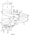
- the regenerative thermal afterburning apparatus has two regenerators A and B, which are connected to a burner 2 or an electric heater through a common combustion chamber 1.
- the combustion chamber 1 in which the temperature is for example 900 ° C, the exhaust gas is thermally cleaned.
- regenerators A and B are divided into two in each case in the flow direction. That is, they each consist of a lower, facing away from the combustion chamber 7 section A 'and B' and an upper, the combustion chamber 1 facing section A "and B".
- the sections A ', A ", B' and B" are each filled with heat storage bodies 3.
- each regenerator A and B are connected to each other via a line 4 and 5, which are each provided with a shut-off valve V-5A and V-5B.
- the two regenerators A and B have a common SCR catalyst 6.
- the nozzles 11 are arranged in the chamber 9 upstream of a mixer 12, for example from baffles. From the mixer 12 a line 13 leads into the upper end of a chamber 14 in which the SCR catalyst 6 is arranged.
- the clean gas formed after passing through the SCR catalyst 6 is supplied from the chamber 14 via the line 8 to the lower portion A 'and B' of the Regenerator A or B respectively connected as a clean gas outlet regenerator at the upper end.
- the raw gas is supplied with a blower 16 via a raw gas line 17, to which the two regenerators A and B via shut-off valves V-1A and V-1 B are connected, in each case at the lower end of its lower portion A 'and B'.
- the clean gas is discharged via a clean gas line 18 and the fireplace 19 to the outside.
- the clean gas line is connected to the lower end of the lower sections A 'and B' of the two reactors A and B via shut-off valves V-2A and V-2B.
- nozzles 20, 21 are respectively provided, with which a nitrogen-hydrogen compound is supplied as reducing agent in order to at least supply the nitrogen oxides in the combustion chamber partially vorzuentsticken, ie thermally, so not catalytically.
- the nozzle or group of nozzles is activated, which is arranged above the raw gas tower in order to maximize the residence time for the non-catalytic reduction.
- regenerators A and B are operated alternately, d. H. either as a raw gas inlet regenerator, the heat storage body 3 have been previously heated to heat the raw gas entering the combustion chamber 1, or as a clean gas outlet regenerator, from which the clean gas with its heat to the heat storage body of the regenerator A or B for the next Cycle exits.
- the obturator V-1A and the obturator V-2B are opened and the shut-off members V-2A and V-1 B are closed. Further, then the obturator V-5A is opened, which connects the two sections A 'and A "of the regenerator A via the line 4, while the shut-off valves V-4A and V-6A connect the regenerator A with the SCR catalyst 6, are closed.
- the obturator V-5B is closed, which connects the two sections B “and B 'via the line 5, while the shut-off valves V-6B and V-4B are opened such that the exhaust gas exiting from the section B "and thermally pre-cleaned and heated after release of a portion of its heat to the heat storage body 3 of the section B" and after admixing the nitrogen hydrogen compound with the nozzles 11 in the static mixer 12 and 15 respectively is mixed and purified by SCR reaction with the catalyst 6 purified via the line 8 in the lower portion B 'enters to heat by its heat, the heat storage body 3 in the lower portion B'.
- the height of the upper portion B "of the regenerator B in relation to the height of the lower portion B ' is selected such that the exhaust gas supplied from the portion B" to the catalytic converter 6 is optimum for the SCR reaction Temperature of for example 250 to 350 ° C, in particular 280 to 320 ° C has.
- the total height of the regenerator is selected so that the clean gas passes at a temperature of, for example, 30 to 60 ° C above the raw gas temperature in the clean gas line 18, and the fireplace 19 to the outside.
- FIG. 2a and FIG. 2b is the regenerator A according to FIG. 1 on the one hand as raw gas inlet regenerator ( FIG. 2a ) or clean gas outlet regenerator ( FIG. 2b ).
- the entering raw gas is in FIG. 2a by the arrow P1 and the exiting clean gas in FIG. 2b illustrated by the arrow P2.
- FIG. 2a and 2 B it can be seen, while the catalyst 6, the bed 15, the nozzles 11 for supplying the hydrogen-nitrogen compound and designed as poppet valves shut-off valves V-4A, V-5A and V-6A provided in an attachment 22 side of the regenerator A.
- shut-off valves V-1A and V-2A on the raw gas line 17 and clean gas line 18 are likewise designed as poppet valves.
- the second regenerator B ( FIG. 1 ) is located behind the regenerator A and therefore in FIG. 2a and 2 B not to be seen. This arrangement also applies to other existing regenerators.
- the attachment 22 has a two regenerators A and B common upper collecting channel 25 for supplying the exhaust gas thermally cleaned in the combustion chamber 1 from the upper portion A “and B" to the catalyst 6 and a common lower collecting channel 26 for the with the catalyst. 6 cleaned clean gas, which is the lower section A 'and B' of the regenerator A and B, respectively.
- a separate gap 27 is provided in the attachment 22 for each regenerator A, B, into which the raw gas or clean gas of the respective regenerator A, B flows and from which the catalyst 6 through a wall 28 is disconnected.
- the poppet valve V-5A of the regenerator A (or the poppet valve V-5B of in FIG. 2a and 2 B regenerator B), not shown, while the poppet valves V-6A and V-4A (or V-6B and V-4B) are closed to the collecting channels 25 and 26.
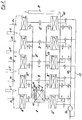
- the device after FIG. 3 has five regenerators A to E, all in the same way as the regenerators A and B after FIG. 1 and FIG. 2a and 2 B are formed. That is, all the regenerators A to E, which are preferably arranged perpendicular to each other, have heat storage body 3 filled sections A ', A ", B', B” ... and a common combustion chamber 1 and a common catalyst 6.
- the catalyst 6 is preferably arranged in a lateral attachment, which accordingly FIG. 2a and 2 B attached and formed laterally.
- the upper manifold 25 and the lower manifold 26 according to FIG. 2a and 2 B are in FIG. 3 shown schematically.
- regenerators A to E In each case one pair of the regenerators A to E is connected to the raw gas inlet, another pair of the regenerators A to E to clean gas outlet, while the fifth regenerator A to E is provided for rinsing.
- regenerators A to E with the lower end of their lower sections A ', B' ... via the shut-off valves V-3A (see. FIG. 2a and 2 B ) to V-3E connected to a purge gas line 26, which supplies the regenerated from the regenerators A to E with purified exhaust gas from the combustion chamber raw gas of the crude gas line 17 upstream of the blower 16.
Description
Die Erfindung bezieht sich auf ein Verfahren nach dem Oberbegriff des Anspruchs 1. Sie hat auch eine Vorrichtung zur Durchführung des Verfahrens sowie die Verwendung der Vorrichtung zum Gegenstand.The invention relates to a method according to the preamble of
Die Kombination einer regenerativen thermischen Nachverbrennungsanlage mit einer selektiven katalytischen Reduktion (englisch: selective catalytic reduction, SCR) ist aus
Auch
Aus
Bei diesem Verfahren ist nachteilig, dass sich damit in Strömungsrichtung über den SCR-Katalysator ein stark schwankendes Temperaturprofil wie im Wärmetauscher einstellt und sich auch noch mit der Zykluszeit ändert. Dies macht es verfahrensbedingt unmöglich, den SCR-Katalysator über sein gesamtes Volumen bei seiner optimalen Temperatur zu betreiben. Zugleich stellt der ständige Temperaturwechsel eine hohe mechanische Beanspruchung für den SCR-Katalysator dar.In this method, it is disadvantageous that in the flow direction over the SCR catalyst, a strongly fluctuating temperature profile is set as in the heat exchanger and also changes with the cycle time. This makes it procedurally impossible to operate the SCR catalyst over its entire volume at its optimum temperature. At the same time, the constant temperature change represents a high mechanical stress for the SCR catalyst.
Ein weiterer Nachteil ist, dass bei der Reduktion von NOx zu Stickstoff (N2) Wärme frei wird. Bei hohen NOx-Konzentrationen limitiert alleine diese frei werdende Wärme die maximale NOx-Eintrittskonzentration, da sonst der SCR-Katalysator durch Überhitzen thermisch schnell altern würde. Muss noch ein Temperaturprofil und dessen Schwankungen über die Länge des SCR-Katalysators berücksichtigt werden, verringert sich die maximale NOx-Eintrittskonzentration dramatisch.Another disadvantage is that heat is released in the reduction of NOx to nitrogen (N 2 ). At high NOx concentrations alone, this released heat limits the maximum NOx inlet concentration, otherwise the SCR catalyst would age rapidly due to overheating. If a temperature profile and its variations over the length of the SCR catalytic converter still have to be taken into account, the maximum NOx inlet concentration decreases dramatically.
Ein weiterer entscheidender Nachteil besteht darin, dass bei dem bekannten Verfahren mit drei Regeneratoren mindestens 3 Gitterroste pro Regenerator aus statischen Gründen notwendig sind, wenn man homogenes Extrudat oder gewellte oder Corrugat SCR-Katalysatoren aus relativ weichem Material verwenden will, und nicht die wesentlich kostspieligeren mit SCR-katalytisch aktivem Washcoat beschichteten keramischen Wärmetauscher-Waben.Another major disadvantage is that in the known method with three regenerators at least 3 gratings per regenerator are necessary for static reasons, if you want to use homogeneous extrudate or corrugated or corrugated SCR catalysts made of relatively soft material, and not the much more expensive with SCR catalytically active washcoat coated ceramic heat exchanger honeycomb.
Außerdem muss in jedem Regenerator ein Katalysator in ausreichender Menge vorgesehen sein, was bei einer Anlage mit zwei Regeneratoren das doppelte und bei einer Anlage mit drei Regeneratoren im Vergleich zu einer einfachen SCR-Anlage die dreifache Katalysatormenge bedeutet.In addition, a catalyst must be provided in sufficient quantity in each regenerator, which means twice as much for a system with two regenerators and three times as much for a system with three regenerators compared to a simple SCR system.
Aufgabe der Erfindung ist es, einerseits den gesamten Energieinhalt aus der thermischen Oxidation oder Nachverbrennung von organischen Komponenten sowie Kohlenstoffmonoxid (CO) bzw. der thermischen Reduktion von Lachgas (N2O) zu Stickstoff (N2) in einem thermisch-regenerativen Verfahren möglichst ohne externe Energiezufuhr mittels der bei der Reaktion erzeugten Temperaturerhöhung zu nutzen und diese zusätzlich für die Entstickung mittels einer SCR nutzbar zu machen und andererseits die Möglichkeit zu schaffen, den SCR-Katalysator mit seiner optimalen Betriebstemperatur ohne separate Energiezufuhr zu betreiben und dies über sein gesamtes Volumen.The object of the invention is, on the one hand, the entire energy content from the thermal oxidation or afterburning of organic components and carbon monoxide (CO) or the thermal reduction of nitrous oxide (N 2 O) to nitrogen (N 2 ) in a thermal-regenerative process as possible without to use external energy supply by means of the temperature increase generated during the reaction and to make these additionally usable for the denitration by means of an SCR and on the other hand to create the possibility of To operate SCR catalyst with its optimum operating temperature without separate power supply and this over its entire volume.
Dies wird erfindungsgemäß mit dem im Anspruch 1 gekennzeichneten Verfahren erreicht. In den Ansprüchen 2 bis 9 sind bevorzugte Ausführungsformen des erfindungsgemäßen Verfahrens wiedergegeben. Der Anspruch 10, der eine bevorzugte Vorrichtung zur Durchführung des erfindungsgemäßen Verfahrens zum Gegenstand hat, wird durch die Maßnahmen der Ansprüche 11 bis 14 weiter ausgestaltet. Der Anspruch 15 betrifft bevorzugte Verwendungen der erfindungsgemäßen Vorrichtung.This is achieved according to the invention with the method characterized in
Nach der Erfindung wird das Abgas, welches mit Luftsauerstoff oxidierbare, thermisch abreinigbare Verbindungen sowie Stickoxide und/oder Verbindungen enthält, die bei der thermischen Abreinigung Stickoxide bilden, in einer thermischen Nachverbrennungsanlage gereinigt. Bei den oxidierbaren, thermisch abreinigbaren Verbindungen handelt es sich insbesondere um flüchtige organische Verbindungen (VOCs für volatile organic compounds), Kohlenmonoxid, Ammoniak und Lachgas, wobei Ammoniak (NH3) zu Stickstoff (N2), NOx und Wasser und wobei Lachgas (N2O) zu N2 reduziert und O2, sowie zu NOx oxidiert wird. Außer durch Lachgas können Stickoxide insbesondere thermisch, bei Temperaturen oberhalb 1100 °C (wie z.B. in der Brennerflamme) oder durch stickstoffhaltige organische Verbindungen, beispielsweise Amine, Nitrile oder Cyanide, bei der thermischen Abreinigung, also ohne Verwendung eines Katalysators, gebildet werden.According to the invention, the exhaust gas containing oxygen-oxidizable, thermally abreinigbare compounds and nitrogen oxides and / or compounds which form nitrogen oxides during thermal cleaning, cleaned in a thermal afterburner. The oxidisable, thermally ablatable compounds are, in particular, volatile organic compounds (VOCs for volatile organic compounds), carbon monoxide, ammonia and nitrous oxide, ammonia (NH 3 ) being nitrogen (N 2 ), NOx and water and nitrous oxide (N 2 O) is reduced to N 2 and O 2 , as well as oxidized to NOx. Apart from nitrous oxide, nitrogen oxides can be formed in particular thermally, at temperatures above 1100 ° C. (for example in the burner flame) or by nitrogen-containing organic compounds, for example amines, nitriles or cyanides, during thermal cleaning, ie without the use of a catalyst.
Die Nachverbrennungsanlage weist wenigstens zwei, mit Wärmespeicherkörpern gefüllte und mit einer gemeinsamen Brennkammer verbundene Regeneratoren auf. Dabei wird das zu reinigende Abgas wechselweise einem Rohgaseintritt-Regenerator, dessen Wärmespeicherkörper zuvor erwärmt worden sind, und das aus der Brennkammer austretende, thermisch abgereinigte Abgas einem Reingasaustritt-Regenerator zur Erwärmung von dessen Wärmespeicherkörpern und zur SCR-Reaktion der Stickoxide zu Stickstoff mit einem Reduktionsmittel zugeführt.The post-combustion plant has at least two regenerators filled with heat storage bodies and connected to a common combustion chamber. In this case, the exhaust gas to be cleaned is alternately a Rohgaseintritt regenerator, the heat storage body have been previously heated, and exiting from the combustion chamber, thermally cleaned exhaust a clean gas outlet regenerator to heat its heat storage bodies and the SCR reaction of nitrogen oxides to nitrogen with a reducing agent fed.
Dabei braucht unabhängig von der Rohgastemperatur keine zusätzliche Energie für die Erreichung der erforderlichen Temperatur für die SCR-Reaktion aufgewendet zu werden.Regardless of the raw gas temperature, no additional energy needs to be expended for achieving the required temperature for the SCR reaction.
Erfindungsgemäß sind die wenigstens zwei Regeneratoren der Nachverbrennungsanlage in Strömungsrichtung jeweils in einen ersten, von der Brennkammer abgewandten und einen zweiten, der Brennkammer zugewandten Regeneratorabschnitt zweigeteilt. Dabei weisen die wenigstens zwei Regeneratoren einen gemeinsamen SCR-Katalysator auf, wobei das in der Brennkammer thermisch abgereinigte Abgas nach Abkühlung in dem der Brennkammer benachbarten Abschnitt des Reingasaustritt-Regenerators die zur SCR-Reaktion erforderliche Temperatur von ca. 300°C erreicht und mit dem Reduktionsmittel vermischt dem gemeinsamen Katalysator zur Bildung von Reingas zugeführt wird.According to the invention, the at least two regenerators of the post-combustion plant are divided into two in the direction of flow in each case into a first regenerator section facing away from the combustion chamber and a second regenerator section facing the combustion chamber. In this case, the at least two regenerators have a common SCR catalyst, wherein the exhaust gas thermally cleaned in the combustion chamber after cooling in the combustion chamber adjacent portion of the clean gas outlet regenerator reaches the temperature required for SCR reaction of about 300 ° C and with the Reducing agent is mixed supplied to the common catalyst for the formation of clean gas.
Das mit dem SCR-Katalysator erhaltene Reingas gibt seine Wärme an die Wärmespeicherkörper des zweiten, von der Brennkammer abgewandten Abschnitts des Reingasaustritts-Regenerators ab und strömt dann ins Freie.The clean gas obtained with the SCR catalyst releases its heat to the heat storage body of the second, facing away from the combustion chamber portion of the clean gas outlet regenerator and then flows into the open.
Nach dem erfindungsgemäßen Verfahren mit dem Vorteil der konstanten Durchströmung des SCR-Katalysators bei einer optimalen Katalysatortemperatur können auch mechanisch und hinsichtlich Temperaturvvechsel wenig beanspruchbare aber dafür preiswertere extrudierte SCR-Katalysatoren beispielsweise auf der Basis von Vanadiumpentoxid (V2O5), Wolframtrioxid (WO3) und/oder Titandioxid (TiO2) verwendet werden.According to the novel process with the advantage of constant flow through the SCR catalyst at an optimum catalyst temperature, extruded SCR catalysts which are less demanding but cheaper can be used, for example on the basis of vanadium pentoxide (V 2 O 5 ), tungsten trioxide (WO 3 ) and / or titanium dioxide (TiO 2 ).
Das erfindungsgemäße Verfahren kann unabhängig von der Anzahl der Regeneratoren mit nur einem SCR-Katalysator durchgeführt werden, der unabhängig vom Zyklus der thermischen Nachverbrennungsanlage stets in ein und derselben Richtung durchströmt wird.The inventive method can be carried out regardless of the number of regenerators with only one SCR catalyst, which is always flowed through in one and the same direction regardless of the cycle of the thermal afterburner.
Für das Erreichen der für die SCR-Reaktion erforderlichen Temperatur braucht keine zusätzliche Energie aufgebracht zu werden, da das Abgas im Reingasaustritt-Regenerator an dem der Brennkammer zugewandten Abschnitt, also an geeigneter Stelle entnommen werden kann. Diese Stelle wird so gewählt, dass das in der Brennkammer bei vorzugsweise mindestens 800°C abgereinigte Abgas nach Durchströmen des der Brennkammer benachbarten Abschnitts des Reingasaustritts-Regenerators derart abgekühlt ist, dass die für die SCR-Reaktion erforderliche Temperatur, die vorzugsweise 200 bis 400°C, insbesondere 250 bis 350°C und besonders bevorzugt 280 bis 320°C beträgt, eingestellt wird.No additional energy needs to be applied to reach the temperature required for the SCR reaction, since the exhaust gas in the clean gas outlet regenerator can be removed at the section facing the combustion chamber, ie at a suitable point. This position is chosen that in the combustion chamber at preferably at least 800 ° C cleaned off exhaust gas after flowing through the combustion chamber adjacent portion of the clean gas outlet regenerator is cooled such that the temperature required for the SCR reaction, preferably 200 to 400 ° C, in particular 250 to 350 ° C and particularly preferably 280 to 320 ° C is set.
Um die Selektivität des SCR Katalysators sicherzustellen und die Alterung eines SCR-Katalysators gering zu halten, aber auch um die Oxidation von SO2 zu SO3 zu verhindern, muss dieses definierte Fenster der Betriebstemperatur gewählt werden.To ensure the selectivity of the SCR catalyst and to minimize the aging of an SCR catalyst, but also to prevent the oxidation of SO 2 to SO 3 , this defined operating temperature window must be selected.
Die Stickoxide in der Brennkammer können durch Zugabe eines Reduktionsmittels in die Brennkammer durch Reduktion zu Stickstoff thermisch, also nicht katalytisch, vorentstickt werden.The nitrogen oxides in the combustion chamber can be thermally, ie not catalytically, pre-deesterified by adding a reducing agent into the combustion chamber by reduction to nitrogen.
Zur Reduktion der Stickoxide in der Brennkammer wird vorzugsweise eine Stickstoffwasserstoffverbindung als wässrige Lösung verwendet, Als Stickstoffwasserstoffverbindung kann beispielsweise Ammoniak, Harnstoff oder Carbaminsäure verwendet werden.In order to reduce the nitrogen oxides in the combustion chamber, a nitrogen-hydrogen compound is preferably used as the aqueous solution. As the nitrogen-hydrogen compound, for example, ammonia, urea or carbamic acid can be used.
Um die zur thermischen Entstickung in der Brennkammer erforderliche Reaktionstemperatur zu senken, können der Stickstoffwasserstoffverbindung Additive, beispielsweise organische Verbindungen, wie Alkohole, zugesetzt werden. Zur optimalen Verteilung der wässrigen Lösung der Stickstoffwasserstoffverbindung in der Brennkammer können Zweistoffdüsen oder Ultraschallzerstäuber mit jeweils konstantem oder pulsierendem Pumpenvordruck vorgesehen sein.In order to reduce the reaction temperature required for thermal denitration in the combustion chamber, additives, for example organic compounds such as alcohols, can be added to the nitrogen hydrogen compound. For optimum distribution of the aqueous solution of the hydrogen fluoride compound in the combustion chamber, two-component nozzles or ultrasonic atomizers each with a constant or pulsating pump pressure can be provided.
Durch die Zufuhr des Reduktionsmittels in die Brennkammer werden typisch etwa 50 % der Stickstoffoxidfracht des Rohgases entfernt, ein allfälliger Ammoniakschlupf bei der thermischen NOx-Reduktion in der Brennkammer wird mit dem nachfolgenden SCR-Katalysator als zusätzliches Reduktionsmittel genutzt, so dass es erfindungsgemäß zu keiner Ammoniakemission und gleichzeitig zur Verringerung des Reduktionsmittelbedarfs bei der SCR-Reaktion kommt. Dabei kann in die Brennkammer als Reduktionsmittel auch ein VOC-haltiges Reduktionsmittel eingesetzt werden, beispielsweise Abwasser aus der Fotoindustrie oder der Chemischen Industrie, welches neben Ammoniak auch beträchtliche Mengen an organischen Lösungsmitteln enthält.By supplying the reducing agent into the combustion chamber typically about 50% of the nitrogen oxide of the raw gas is removed, a possible ammonia slip in the thermal NOx reduction in the combustion chamber is used with the following SCR catalyst as an additional reducing agent, so that according to the invention to no ammonia emission and at the same time reducing the reductant demand in the SCR reaction. It can also be used as a reducing agent in the combustion chamber VOC-containing reducing agent can be used, for example wastewater from the photographic industry or the chemical industry, which also contains considerable amounts of organic solvents in addition to ammonia.
Zur SCR-Reaktion wird die Stickstoffwasserstoffverbindung, wie z.B. Ammoniak als Reduktionsmittel entweder als wässrige Lösung oder gasförmig über eine einstufige oder zweistufige Mischeinrichtung dem aus dem der Brennkammer zugewandten, zweiten Abschnitt des Reingasaustritt-Regenerators direkt stromauf des SCR-Katalysators zugeführt.For the SCR reaction, the nitrogen-hydrogen compound, e.g. Ammonia as a reducing agent either as an aqueous solution or gaseous via a single-stage or two-stage mixing device fed from the combustion chamber facing the second portion of the clean gas outlet regenerator directly upstream of the SCR catalyst.
Die Wärmespeicherkörper der regenerativen thermischen Nachverbrennungsanlage bestehen vorzugsweise aus extrudierten prismenförmigen keramischen Wärmespeicherkörpern, die eine Vielzahl von in Gasströmungsrichtung verlaufende Gasdurchtrittskanäle aufweisen, wie beispielsweise in
Das thermisch abgereinigte Abgas strömt vorzugsweise vor Mischung mit dem Reduktionsmittel durch eine Keramikschüttung zur Vergleichsmäßigung der Temperatur des Abgases vor Eintritt in den SCR-Katalysator. Die Keramikschüttung besteht aus Keramikformkörpern, vorzugsweise in Sattel- oder Ringform. Sie verteilt zugleich das zugegebene Reduktionsmittel über die Querschnittsfläche des SCR-Katalysators und dämpft die Temperaturschwankungen am Eintritt in den SCR Katalysator.The thermally-cleaned exhaust gas preferably flows through a ceramic bed prior to mixing with the reducing agent to equalize the temperature of the exhaust gas prior to entering the SCR catalyst. The ceramic packing consists of ceramic moldings, preferably in saddle or ring form. At the same time it distributes the added reducing agent over the cross-sectional area of the SCR catalyst and dampens the temperature fluctuations at the inlet to the SCR catalyst.
Nach der Erfindung wird also das Abgas in Zyklen wechselweise wenigstens einem Rohgaseintritt-Regenerator zugeführt, dessen Wärmespeicherkörper zuvor erwärmt worden sind. Das so erwärmte Abgas wird der Brennkammer zugeführt, welche eine hohe Temperatur von mehr als 800°C, insbesondere 850 bis 1000°C aufweist. Bei dieser hohen Temperatur werden die VOCs in der Brennkammer durch den Luftsauerstoff in dem Abgas verbrannt bzw. Lachgas thermisch zu Stickstoff umgewandelt. Die dabei entstandene Wärme wird beim Durchströmen des der Brennkammer zugewandten Abschnitts des Reingasaustritt-Regenerators an diesem Abschnitt abgegeben. Durch Ausschleusen des Abgases nach dem der Brennkammer zugewandten Abschnitts des zweigeteilten Reingasaustritt-Regenerators ist es möglich, in allen Zyklen in derselben Richtung das Abgas über den SCR-Katalysator zu führen. Das mit dem Reduktionsmittel vermischte Abgas wird nach Strömungsverteilung und Temperaturvergleichsmäßigung über den Zyklus durch die Keramikschüttung dem SCR-Katalysator bei einer optimalen Betriebstemperatur von ca. 300°Czugeführt. Das Reingas, also das nunmehr auch mit dem SCR-Katalysator gereinigte Abgas, gibt an den von der Brennkammer abgewandten Abschnitt des zweigeteilten Reingasaustritt-Regenerators, die verbleibende Wärme ab, womit auch noch die aus der SCR-Reaktion entstandene Wärme genutzt werden kann.According to the invention, therefore, the exhaust gas in cycles alternately supplied to at least one raw gas inlet regenerator, the heat storage body have been previously heated. The thus heated exhaust gas is supplied to the combustion chamber, which has a high temperature of more than 800 ° C, in particular 850 to 1000 ° C. At this high temperature, the VOCs in the combustion chamber are burned by the atmospheric oxygen in the exhaust gas or thermally to nitrous oxide Converted to nitrogen. The resulting heat is released as it flows through the combustion chamber facing portion of the clean gas outlet regenerator at this section. By discharging the exhaust gas to the combustion chamber facing portion of the two-part clean gas outlet regenerator, it is possible to guide the exhaust gas through the SCR catalyst in all cycles in the same direction. The exhaust gas mixed with the reducing agent is supplied to the SCR catalyst at an optimum operating temperature of about 300 ° C after flow distribution and temperature uniformity over the cycle through the ceramic bed. The clean gas, so now also cleaned with the SCR catalyst exhaust gas, at the side facing away from the combustion chamber portion of the two-part clean gas outlet regenerator, the remaining heat, which also the resulting from the SCR reaction heat can be used.
Die Verweilzeit des Abgases in der Brennkammer beträgt vorzugsweise 0,5 bis 3, insbesondere 0,7 bis 1,5 Sekunden beispielsweise bei 800 bis 850°C wenn keine thermische Reduktion mit einem Reduktionsmittel durchgeführt wird. Dem gegenüber beträgt bei einer thermischen SNCR Reduktion mit einem Reduktionsmittel die Verweilzeit vorzugsweise 1 bis 4, insbesondere 1,5 bis 2 Sekunden bei einer Brennkammertemperatur von mehr als 850°C, insbesondere 900 bis 950°C. Bei der thermischen Zersetzung von Lachgas beträgt die Verweilzeit vorzugsweise 1 bis 3 s, insbesondere 1,5 bis 2 s bei einer Brennkammertemperatur von vorzugsweise 900 - 1000 °C, insbesondere 950 - 970 °C.The residence time of the exhaust gas in the combustion chamber is preferably 0.5 to 3, in particular 0.7 to 1.5 seconds, for example at 800 to 850 ° C when no thermal reduction is carried out with a reducing agent. On the other hand, in a thermal SNCR reduction with a reducing agent, the residence time is preferably 1 to 4, in particular 1.5 to 2 seconds at a combustion chamber temperature of more than 850 ° C, in particular 900 to 950 ° C. In the case of the thermal decomposition of nitrous oxide, the residence time is preferably 1 to 3 s, in particular 1.5 to 2 s, at a combustion chamber temperature of preferably 900-1000 ° C., in particular 950-970 ° C.
Vorzugsweise wird jeder Rohgaseintritt-Regenerator, um darin enthaltene Abgasreste zu entfernen, mit Reingas aus einem weiteren zweigeteilten Regenerator vor dem Wechsel der Abgasströmungsrichtung einen Zyklus lang gespült. Damit kann für VOCs oder Kohlenmonoxid eine Reinigungsleistung von über 99,5 % erzielt werden.Preferably, each raw gas inlet regenerator to remove exhaust gas residues contained therein is purged with clean gas from another two-part regenerator before changing the exhaust gas flow direction for one cycle. This can be achieved for VOCs or carbon monoxide cleaning performance of over 99.5%.
Anstelle von zwei oder drei Regeneratoren wird bei größeren Abgasdurchsätzen vorteilhafterweise ein Vielfaches an erfindungsgemäß ausgebildetenInstead of two or three regenerators, a multiple of inventively designed with larger exhaust gas flow rates advantageously
Regeneratorpaaren vorgesehen. Dadurch kann die Größe der einzelnen Regeneratoren auf ein transportierbares Maß begrenzt werden. Außerdem wird durch die sequenzielle Weiterschaltung der Regeneratoren die Temperaturwechselbelastung des SCR-Katalysators reduziert. So beträgt bei einer Anlage mit 5 Regeneratoren die Wechselbelastung für den SCR-Katalysator nur mehr 50 % und bei einer Anlage mit 7 Regeneratoren lediglich 33 % im Vergleich zu einer Anlage mit 3 Regeneratoren.Regenerator pairs provided. As a result, the size of the individual regenerators can be limited to a transportable measure. In addition, the thermal cycling of the SCR catalyst is reduced by the sequential advancement of the regenerators. Thus, in a system with 5 regenerators, the alternating load for the SCR catalytic converter is only 50% and for a system with 7 regenerators only 33% compared to a system with 3 regenerators.
Bei der Vorrichtung zur Durchführung des erfindungsgemäßen Verfahrens sind wenigstens 2 mit einer gemeinsamen Brennkammer verbundene Regeneratoren vorzugsweise parallel nebeneinander angeordnet. Dabei weisen sie jeweils 2 vorzugsweise senkrecht übereinander angeordnete mit Wärmespeicherkörpern gefüllte Abschnitte auf. Seitlich an den Abschnitten ist ein den mindestens 2 Regeneratoren gemeinsamer Anbau mit dem SCR-Katalysator angeschlossen.In the apparatus for carrying out the method according to the invention, at least two regenerators connected to a common combustion chamber are preferably arranged parallel to one another. In this case, they each have two preferably vertically stacked with heat storage bodies filled sections. On the sides of the sections, a common cultivation with the SCR catalyst is connected to the at least 2 regenerators.
Der Anbau weist zum Verbinden des Katalysators mit dem unteren Abschnitt und dem oberen Abschnitt der wenigstens zwei Regeneratoren Absperrorgane, vorzugsweise Tellerventile auf, die derart angeordnet sind, dass der SCR-Katalysator durchströmt oder umgangen werden kann, also nicht durchströmt wird.The attachment has for connecting the catalyst to the lower portion and the upper portion of the at least two regenerators shut-off valves, preferably poppet valves, which are arranged such that the SCR catalyst can flow through or be bypassed, is thus not flowed through.
Die Erfindung ist generell zur Reinigung von Abgas geeignet, welches mit dem Luftsauerstoff im Abgas oxidierbare, thermisch abreinigbare Verbindungen sowie Stickoxide und/oder Verbindungen enthält, die bei der thermischen Abreinigung im Brennraum der Nachverbrennungsanlage Stickoxide bilden.The invention is generally suitable for the purification of exhaust gas, which contains oxidizable, thermally cleanable compounds and nitrogen oxides and / or compounds with the atmospheric oxygen in the exhaust gas, which form nitrogen oxides during the thermal cleaning in the combustion chamber of the post-combustion system.
Das erfindungsgemäße Verfahren und die erfindungsgemäße Vorrichtung sind daher insbesondere zur Reinigung von Abgasen geeignet, die bei der Zementklinker-, Salpetersäure-, Adipinsäure- und Düngemittelherstellung anfallen. Auch ist das erfindungsgemäße Verfahren bzw. die erfindungsgemäße Vorrichtung zur Reinigung der bei der Urantrioxid-Herstellung anfallenden Abgase geeignet, welches durch Erhitzen von Ammoniumdiuranat (yellow cake) in einer Sauerstoffatmosphäre erhalten wird.The inventive method and the device according to the invention are therefore particularly suitable for the purification of exhaust gases incurred in the cement clinker, nitric acid, adipic acid and fertilizer production. The process according to the invention or the device according to the invention is also suitable for purifying the waste gases produced during the production of uranium trioxide, which is obtained by heating ammonium diuranate (yellow cake) in an oxygen atmosphere.
Für eine Vorrichtung mit 5 Regeneratoren mit Spülmöglichkeit ist die zyklische Weiterschaltung, also der Schaltplan der Absperrorgane der Regeneratoren, in der nachfolgenden Tabelle beispielhaft wiedergegeben, wobei die Nummerierung der Absperrorgane 
Die Herstellung von Zementklinker ist ein energieintensiver Prozess, weshalb der Abgasstrom des Drehrohrofens zur Vorwärmung des Rohmehls verwendet wird, um möglichst viel Abwärme im Prozess nutzen zu können. Bei modernen Zementwerken wird auch die Abwärme des Klinkerkühlers genutzt. Dennoch hat der Abluftstrom im Ausmaß von einigen 100.000 Nm3/h eine Temperatur von 130 - 200°C, welche den Wärmeenergiebedarf des Zementwerkes widerspiegelt und weshalb Sekundärbrennstoffe sowie stark kohlenwasserstoffhaltiger Bodenaushub im Rohmehl mitverarbeitet werden. Durch Verdunstung und Teilpyrolyse gelangen die Kohlenwasserstoffe (VOC) und zusätzlich gebildetes Kohlenmonoxid und NOx mit dem gegenläufige Abgasstrom nicht in den heißen Drehrohrofen, sondern zum großen Teil direkt ins Abgas. Durch die erfindungsgemäße Anlage ist eine sichere und effiziente Reinigung dieser großen Palette von Schadstoffen gewährleistet und es ist der Einsatz einer qualitativ und quantitativ größeren Menge an Sekundärrohstoffen und Sekundärbrennstoffen ohne negative Auswirkung auf die Umwelt möglich.The production of cement clinker is an energy-intensive process, which is why the exhaust stream of the rotary kiln is used to preheat the raw meal in order to use as much waste heat in the process. Modern cement plants also use the waste heat from the clinker cooler. Nevertheless, the exhaust air flow in the amount of some 100,000 Nm 3 / h has a temperature of 130 - 200 ° C, which reflects the heat energy demand of the cement plant and why secondary fuels and highly hydrocarbonic soil excavated in raw meal mitverarbeitet. Due to evaporation and partial pyrolysis, the hydrocarbons (VOC) and additionally formed carbon monoxide and NOx with the opposing exhaust gas flow do not enter the hot rotary kiln, but for the most part directly into the exhaust gas. The inventive system ensures safe and efficient cleaning of this large range of pollutants and it is the use of a qualitatively and quantitatively larger amount of secondary raw materials and secondary fuels possible without negative impact on the environment.
Mit der erfindungsgemäßen Anlage (5-Bett Variante) wird der Energieinhalt des Abgases in Form der Schadstoffe genutzt, um im autothermen Betrieb VOCs, CO, und NOx zu reinigen.With the system according to the invention (5-bed variant), the energy content of the exhaust gas in the form of the pollutants is used to clean in autothermal operation VOCs, CO, and NOx.
Dazu wird der regenerative Wärmetauscher genutzt, um das Abgas auf > 800°C vorzuwärmen, wodurch durch Oxidation von CO und VOCs ausreichend Energie zur Aufrechterhaltung dieser Temperatur freigesetzt wird.
Die CO und TOC Reinigung beträgt 99,5 %For this purpose, the regenerative heat exchanger is used to reduce the exhaust gas to> 800 ° C preheating, which releases sufficient energy to maintain this temperature by oxidation of CO and VOCs.
CO and TOC cleaning is 99.5%
Der Reduktionsmittelverbrauch der SCR Stufe beträgt dabei 65 kg/h NH3 (100%) und ist vor allem deshalb so gering, weil durch das erfindungsgemäße Verfahren und die damit verbundene kurzzeitige Erhitzung des Abgases auf >800°C (Gleichgewicht des NOx auf Seite des NO), gefolgt von einer ebenso raschen Abkühlung auch vorhandenes NO2 thermisch zu NO umgewandelt wird.The reducing agent consumption of the SCR stage amounts to 65 kg / h NH 3 (100%) and is above all so low, because of the inventive method and the associated short-term heating of the exhaust gas to> 800 ° C (equilibrium of NOx on the side of NO), followed by equally rapid cooling also existing NO2 is thermally converted to NO.
Hierdurch können auch für diese Anwendungen Grenzwerte, wie sie nach TA-Luft üblich sind, wirtschaftlich eingehalten werden.As a result, limit values, which are customary according to TA-Luft, can be economically maintained even for these applications.
Sowohl zur Herstellung von Düngemitteln als auch Chemikalien wie Ammoniumnitrat, Caprolactam, Adipinsäure, Dinitrotoluol und Nitrobenzol wird zu Beginn Salpetersäure verwendet, die aus Ammoniak hergestellt wird. Dabei wird als Nebenprodukt das Treibhausgas Lachgas (N2O) frei, welches ein ca. 320 mal so hohes Erderwärmungspotential wie CO2 aufweist und daher häufig trotz hoher Investitions- und Betriebskosten katalytisch gereinigt wird, da derzeit noch durch den Handel mit CO2 Zertifikaten eine teilweise Kompensation dieser Kosten möglich ist.Both for the production of fertilizers and chemicals such as Ammonium nitrate, caprolactam, adipic acid, dinitrotoluene and nitrobenzene are initially used to produce nitric acid, which is made from ammonia. As a by-product, the greenhouse gas nitrous oxide (N 2 O) is released, which has a 320 times higher global warming potential as CO 2 and is therefore often catalytically purified despite high investment and operating costs, as currently still by the trade with CO 2 certificates a partial compensation of these costs is possible.
Mit dem erfindungsgemäßen Verfahren ist eine simultane Beseitigung von Lachgas, VOCs und NOx mit deutlich niedrigeren Gesamtkosten möglich.With the method according to the invention a simultaneous elimination of nitrous oxide, VOCs and NOx with significantly lower overall costs is possible.
Zur Produktion von 560 to/d an Ammoniumnitrat werden 7700 kg/h Ammoniak benötigt. Im korrespondierenden "Tailgas" von 70.000 Nm3/h sind 3 g/Nm3 N2O enthalten. Wird ein Katalysator zur N2O Abreinigung verwendet, liegt die Reinigungsleistung deutlich unter 90 %, bei deutlich höheren Gesamtkosten, bedingt durch die rasche Vergiftung des Katalysators (1-3 Produktionszyklen).To produce 560 to / d of ammonium nitrate, 7700 kg / h of ammonia are required. The corresponding "tail gas" of 70,000 Nm 3 / h contains 3 g / Nm 3 N 2 O. If a catalyst is used for N 2 O cleaning, the cleaning performance is well below 90%, at significantly higher total costs, due to the rapid poisoning of the catalyst (1-3 production cycles).
Mit der erfindungsgemäßen Anlage wird Lachgas thermisch zu N2 zersetzt (> 95 % Reinigung). Die in einer Nebenreaktion aus < 14 mol-% des N2O gebildeten Stickoxide werden gemeinsam mit den ohnehin im Abgas enthaltenen Stickoxiden über den integrierten SCR Reaktor gereinigt, ohne das Abgas ein zweites Mal aufheizen zu müssen, wodurch die Betriebskosten auf weniger als die Hälfte gegenüber der rein katalytischen Variante reduziert werden können.Nitrous oxide is thermally decomposed to N 2 with the system according to the invention (> 95% purification). The nitrogen oxides formed in a side reaction from <14 mol% of N 2 O are cleaned together with the nitrogen oxides already contained in the exhaust gas via the integrated SCR reactor, without having to heat the exhaust gas a second time, whereby the operating costs to less than half can be reduced compared to the purely catalytic variant.
Gleichzeitig ist mit dem erfindungsgemäßen Verfahren die Umweltbelastung (VOCs und NOx) um 95 % reduziert (Nur die halbe Emission der rein katalytischen Variante) und zusätzlich werden auch die Stickoxide reduziert und allfällig vorhandene Methanemissionen aus dem Prozess gereinigt und energetisch genutzt.At the same time, the environmental load (VOCs and NOx) is reduced by 95% with the method according to the invention (only half the emission of the purely catalytic variant) and, in addition, the nitrogen oxides are reduced and any existing methane emissions from the process are purified and utilized energetically.
Durch die Kombination SCR und thermischer SNCR, also nicht katalytischer Entstickung ist eine extrem hohe Reinigungsleistung erreichbar. Da der Reduktionsmittelverbrauch der thermischen Reduktion ca. doppelt so hoch ist wie für die SCR, kann bei frischem SCR Katalysator hauptsächlich dieser zur NOx Reduktion verwendet werden und bei Alterung oder partieller Vergiftung desselben entsprechend die thermische Entstickung mitverwendet werden, um die Reingaskonzentration stabil niedrig zu halten.By combining SCR and thermal SNCR, ie non-catalytic denitrification, an extremely high cleaning performance can be achieved. Since the reducing agent consumption of the thermal reduction is about twice as high as for the SCR, with fresh SCR catalyst mainly this can be used for NOx reduction and in case of aging or partial poisoning of the same In accordance with the thermal denitrification mitverwendet to keep the clean gas concentration stable low.
Nachstehend ist die Erfindung anhand der beigefügten Zeichnung beispielhaft näher erläutert. Darin zeigen jeweils schematisch:
-
Figur 1 -
Figur 2a und2b jeweils einen Schnitt durch einen Regenerator als Rohgaseintritt-Regenerator bzw. Reingasaustritt-Regenerator einer Abgasreinigungsvorrichtung mit zwei Regeneratoren; und -
Figur 3
-
FIG. 1 an exhaust gas purification device with two reactors; -
FIG. 2a and2 B in each case a section through a regenerator as Rohgaseintritt regenerator or pure gas outlet regenerator of an exhaust gas purification device with two regenerators; and -
FIG. 3 an exhaust gas purification device with 5 regenerators.
Gemäß
Die Regeneratoren A und B sind jeweils in Strömungsrichtung zweigeteilt. Das heißt sie bestehen jeweils aus einem unteren, von der Brennkammer 7 abgewandten Abschnitt A' bzw. B' und einem oberen, der Brennkammer 1 zugewandten Abschnitt A" und B". Die Abschnitte A', A", B'und B" sind jeweils mit Wärmespeicherkörpern 3 gefüllt.The regenerators A and B are divided into two in each case in the flow direction. That is, they each consist of a lower, facing away from the combustion chamber 7 section A 'and B' and an upper, the
Die beiden Abschnitte A', A" und B', B" jedes Regenerators A und B sind über eine Leitung 4 bzw. 5, die jeweils mit einem Absperrorgan V-5A und V-5B versehen sind, miteinander verbunden.The two sections A ', A "and B', B" of each regenerator A and B are connected to each other via a line 4 and 5, which are each provided with a shut-off valve V-5A and V-5B.
Die beiden Regeneratoren A und B weisen einen gemeinsamen SCR-Katalysator 6 auf.The two regenerators A and B have a
Dazu sind die oberen Abschnitte A" und B" an ihrem unteren Ende über ein Absperrorgan V-6A und V-6B mit einer Leitung 7 und die unteren Abschnitte A' und B' an ihrem oberen Ende Absperrorgane über V-4A und V-5B mit einer Leitung 8 verbunden.For this purpose, the upper portions A "and B" at its lower end via a valve V-6A and V-6B with a line 7 and the lower portions A 'and B' at its upper end shut-off valves on V-4A and V-5B connected to a
Die obere Leitung 7, über die das in der Brennkammer 1 thermisch abgereinigte Abgas je nach Schaltung der Absperrorgane V-6A bzw. V-6B zugeführt wird, ist an eine Kammer 9 angeschlossen, welche beispielsweise einen Rechen mit Düsen 11 zur Zufuhr einer Stickstoffwasserstoffverbindung als Reduktionsmittel für die SCR-Reaktion mit dem Katalysator 6 aufweist.The upper line 7, via which the exhaust gas thermally cleaned in the
Die Düsen 11 sind in der Kammer 9 stromaufwärts eines Mischers 12, beispielsweise aus Schikanen, angeordnet. Von dem Mischer 12 führt eine Leitung 13 in das obere Ende einer Kammer 14, in der der SCR-Katalysator 6 angeordnet ist.The
Zwischen der Stelle, an der die Leitung 13 in die Kammer 14 mündet, und dem Katalysator 6 ist eine Keramik-Schüttung 15, beispielsweise aus Sattelkörpern, vorgesehen, die der zusätzlichen Vermischung des Reduktionsmittels mit dem in der Brennkammer 1 thermisch abgereinigten Abgas sowie zur Vergleichsmäßigung der Temperatur des in den Katalysator 6 eintretenden Abgases dient.Between the point at which the line 13 opens into the
Das nach Passieren des SCR-Katalysators 6 gebildete Reingas wird aus der Kammer 14 über die Leitung 8 dem unteren Abschnitt A' bzw. B' des jeweils als Reingasaustritt-Regenerator geschalteten Regenerators A oder B am oberen Ende zugeführt.The clean gas formed after passing through the
Das Rohgas wird mit einem Gebläse 16 über eine Rohgasleitung 17 zugeführt, an die die beiden Regeneratoren A und B über Absperrorgane V-1A und V-1 B angeschlossen sind, und zwar jeweils am unteren Ende ihres unteren Abschnitts A' bzw. B'.The raw gas is supplied with a
Das Reingas wird über eine Reingasleitung 18 und den Kamin 19 ins Freie abgeführt. Dazu ist die Reingasleitung an das untere Ende der unteren Abschnitte A' und B' der beiden Reaktoren A und B über Absperrorgane V-2A und V-2B angeschlossen.The clean gas is discharged via a
In der Brennkammer 1 sind oberhalb der beiden Regeneratoren A und B jeweils Düsen 20, 21 vorgesehen, mit denen eine Stickstoffwasserstoffverbindung als Reduktionsmittel zugeführt wird, um die Stickoxide in der Brennkammer zumindest teilweise, nämlich thermisch, also nicht katalytisch vorzuentsticken.In the
Dabei wird jeweils die Düse oder Gruppe von Düsen aktiviert, die über dem Rohgasturm angeordnet ist, um die Verweilzeit für die nichtkatalytische Reduktion zu maximieren.In each case, the nozzle or group of nozzles is activated, which is arranged above the raw gas tower in order to maximize the residence time for the non-catalytic reduction.
Die Regeneratoren A und B werden wechselweise betrieben, d. h. entweder als Rohgaseintritt-Regenerator, dessen Wärmespeicherkörper 3 zuvor erwärmt worden sind, um das in die Brennkammer 1 eintretende Rohgas aufzuheizen, oder als Reingasaustritt-Regenerator, aus dem das Reingas unter Abgabe seiner Wärme an die Wärmespeicherkörper des Regenerators A bzw. B für den nächsten Zyklus austritt.The regenerators A and B are operated alternately, d. H. either as a raw gas inlet regenerator, the
Das heißt, wenn der Regenerator A den Rohgaseintritt-Regenerator und der Regenerator B den Reingasaustritt-Regenerator bildet, werden das Absperrorgan V-1A und das Absperrorgan V-2B geöffnet und die Absperrorgane V-2A und V-1 B geschlossen. Ferner wird dann das Absperrorgan V-5A geöffnet, das die beiden Abschnitte A' und A" des Regenerators A über die Leitung 4 verbindet, während die Absperrorgane V-4A und V-6A die den Regenerator A mit dem SCR-Katalysator 6 verbinden, geschlossen sind.That is, when the regenerator A forms the raw gas inlet regenerator and the regenerator B forms the clean gas outlet regenerator, the obturator V-1A and the obturator V-2B are opened and the shut-off members V-2A and V-1 B are closed. Further, then the obturator V-5A is opened, which connects the two sections A 'and A "of the regenerator A via the line 4, while the shut-off valves V-4A and V-6A connect the regenerator A with the
Beim Regenerator B, der bei diesem Zyklus den Reingasaustritt-Regenerator bildet, ist dann das Absperrorgan V-5B geschlossen, das die beiden Abschnitte B" und B' über die Leitung 5 verbindet, während die Absperrorgane V-6B und V-4B geöffnet sind, so dass das aus dem Abschnitt B" austretende, in der Brennkammer 1 thermisch vorgereinigte und erwärmte Abgas nach Abgabe eines Teils seiner Wärme an die Wärmespeicherkörper 3 des Abschnitts B" und nach Zumischung der Stickstoffwasserstoffverbindung mit den Düsen 11 im statischen Mischer 12 bzw. 15 gemischt wird und durch SCR-Reaktion mit dem Katalysator 6 gereinigt über die Leitung 8 in den unteren Abschnitt B' eintritt, um durch seine Wärme die Wärmespeicherkörper 3 im unteren Abschnitt B' aufzuheizen.In the regenerator B, which forms the clean gas outlet regenerator in this cycle, then the obturator V-5B is closed, which connects the two sections B "and B 'via the line 5, while the shut-off valves V-6B and V-4B are opened such that the exhaust gas exiting from the section B "and thermally pre-cleaned and heated after release of a portion of its heat to the
Dabei wird die Höhe des oberen Abschnitts B" des Regenerators B im Verhältnis zur Höhe des unteren Abschnitts B' so gewählt, dass das aus dem Abschnitt B" dem Katalysator 6 zugeführte Abgas eine für die SCR-Reaktion optimale Temperatur von beispielsweise 250 bis 350°C, insbesondere 280 bis 320°C aufweist.In this case, the height of the upper portion B "of the regenerator B in relation to the height of the lower portion B 'is selected such that the exhaust gas supplied from the portion B" to the
Insgesamt wird die Gesamthöhe des Regenerators so gewählt, dass das Reingas mit einer Temperatur von beispielsweise 30 bis 60°C über der Rohgastemperatur in die Reingasleitung 18 gelangt, und über den Kamin 19 ins Freie. Entsprechendes gilt für die Höhe der Abschnitte A' und A" des Regenerators A und für alle weiteren parallelen Regeneratoren.Overall, the total height of the regenerator is selected so that the clean gas passes at a temperature of, for example, 30 to 60 ° C above the raw gas temperature in the
Wenn bei dem nächsten Zyklus der Regenerator B den Rohgaseintritt-Regenerator und der Regenerator A den Reingasaustritt-Regenerator bildet, werden die Ventile V-1A, V-2B, V-5A, V-6B und V-4B geschlossen und die Ventile V-2A, V-4A, V-6A und V-5B geöffnet.At the next cycle, if the regenerator B forms the raw gas inlet regenerator and the regenerator A forms the clean gas outlet regenerator, the valves V-1A, V-2B, V-5A, V-6B and V-4B are closed and the valves V- 2A, V-4A, V-6A and V-5B.
In
Wie aus
Die Absperrorgane V-1A und V-2A an der Rohgasleitung 17 bzw. Reingasleitung 18 sind gleichfalls als Tellerventile ausgebildet.The shut-off valves V-1A and V-2A on the
Der zweite Regenerator B (
Im Unterschied zu
Gemäß
Der Anbau 22 weist einen beiden Regeneratoren A und B gemeinsamen oberen Sammelkanal 25 zur Zufuhr des in der Brennkammer 1 thermisch abgereinigten Abgases von dem oberen Abschnitt A" bzw. B" zu dem Katalysator 6 und einen gemeinsamen unteren Sammelkanal 26 für das mit dem Katalysator 6 gereinigte Reingas auf, das dem unteren Abschnitt A' bzw. B' des Regenerators A bzw. B zugeführt wird.The
Zwischen dem oberen Kanal 25 und dem unteren Kanal 26 ist in dem Anbau 22 für jeden Regenerator A, B ein eigener Zwischenraum 27 vorgesehen, in den das Rohgas bzw. Reingas des jeweiligen Regenerators A, B strömt und von dem der Katalysator 6 durch eine Wand 28 getrennt ist.Between the
Wenn der Regenerator A (oder B) den Rohgaseintritt-Regenerator gemäß
Wenn der Regenerator A (oder B) den Reingasaustrittregenerator bildet, sind gemäß
Die Vorrichtung nach
Der Katalysator 6 ist dabei vorzugsweise in einem seitlichen Anbau angeordnet, der entsprechend
Mit den Absperrorganen V-5A bis V-5E sind die Abschnitte A', A", B', B".... jedes Generators A bis E miteinander verbindbar. Mit den Absperrorganen V-6A bis V-6E und V-4A bis V-4E sind die Abschnitte A', A", B', B" ... über den Katalysator 6 im Anbau miteinander verbindbar.With the shut-off devices V-5A to V-5E, the sections A ', A ", B', B" .... of each generator A to E can be connected to one another. With the shut-off valves V-6A to V-6E and V-4A to V-4E, the sections A ', A ", B', B" ... can be connected to one another via the
Die obere Sammelleitung 25 und die untere Sammelleitung 26 gemäß
Jeweils ein Paar der Regeneratoren A bis E ist dabei auf Rohgaseintritt geschaltet, ein weiteres Paar der Regeneratoren A bis E auf Reingasaustritt, während der fünfte Regenerator A bis E zum Spülen vorgesehen ist.In each case one pair of the regenerators A to E is connected to the raw gas inlet, another pair of the regenerators A to E to clean gas outlet, while the fifth regenerator A to E is provided for rinsing.
Dazu sind die Regeneratoren A bis E mit dem unteren Ende ihrer unteren Abschnitte A', B'... über die Absperrorgane V-3A (vgl.
Das zyklische Betriebsschema der Vorrichtung nach
Claims (15)
- Process for the purification of waste gas containing thermally purifiable compounds oxidizable with the oxygen in the waste gas as well as nitrogen oxides and/or compounds forming nitrogen oxides during the thermal purification in a post-combustion system having at least two regenerators (A, B....) filled with heat-accumulator bodies (3) and connected to a common combustion chamber (1), wherein the waste gas is alternately supplied to a raw gas inlet regenerator (A or B), the heat-accumulator bodies (3) of which have been preheated, and the thermally purified waste gas emerging from the combustion chamber (1) is supplied to a clean gas outlet regenerator (B or A) for the heating of its heat-accumulator bodies (3) and the selective catalytic reduction of the nitrogen oxides to nitrogen by means of a reducing agent, characterized in that the at least two regenerators (A, B...) are each divided into two parts in the direction of flow, namely into one regenerator section (A', B') facing away from the combustion chamber (1) and one regenerator section (A", B") facing the combustion chamber (1) and that the at least two regenerators (A, B ...) have a common catalyst (6) for the selective catalytic reduction, wherein, after cooling in the section (A", B") of the clean gas outlet regenerator (A, B ...) adjacent to the combustion chamber (1) to the temperature required for the selective catalytic reduction, and mixing with the reducing agent, the waste gas thermally purified in the combustion chamber (1) is supplied to the common catalyst (6) for forming clean gas, which is directed to the outside after it has conveyed heat to the heat-accumulator bodies (3) of the section (A', B') of the clean gas outlet regenerator (A, B ...) facing away from the combustion chamber (1).
- Process according to claim 1, characterized in that waste gas to be purified contains volatile organic compounds, carbon monoxide, ammonia and/or nitrous oxide as oxidizable, thermally purifiable compounds as well as ammonia, nitrous oxide and/or nitrogen-containing volatile organic compounds as compounds forming nitrogen oxides during the thermal purification.
- Process according to claim 1, characterized in that the temperature required for the selective catalytic reduction is 200 to 400°C.
- Process according to any of the preceding claims, characterized in that the nitrogen oxides existing or being formed in the combustion chamber (1) are thermally pre-denitrified by feeding a reducing agent into the combustion chamber (1).
- Process according to any of the preceding claims, characterized in that the temperature in the combustion chamber (1) is at least 800°C and, in case of thermal pre-denitrification, at least 900°C.
- Process according to any of the preceding claims, characterized in that, after having been mixed with the reducing agent, the thermally purified waste gas flows through a ceramic bulk bed (15) for homogenizing the temperature of the waste gas before it enters the catalyst (6).
- Process according to any of the preceding claims, characterized in that a nitrogen-hydrogen compound is used for reducing the nitrogen oxides in the combustion chamber (1) and/or with the catalyst (6) to nitrogen.
- Process according to any of the preceding claims, characterized in that the residence time of the waste gas in the combustion chamber (1) is 0.3 to 1 second and, in case of thermal pre-denitrification, 1 to 4 seconds.
- Process according to any of the preceding claims, characterized in that a further regenerator (A to E) is provided for purging the raw gas inlet regenerator (A to E) with clean gas before the latter's passing to the clean gas outlet regenerator.
- Device for carrying out the process according to any of the preceding claims, characterized by a post-combustion system with at least two regenerators (A, B) having a common combustion chamber (1) which each have two sections (A', A", B', B") arranged above one another and filled with heat-accumulator bodies (3) and to which a common mounting (22) with the catalyst (6) for the selective catalytic reduction is laterally attached, wherein the mounting (22) has shut-off valves (V-4A, V-5A, V-6A; V-4B, V-5B, V-6B) for connecting the catalyst (6) to the lower section (A', B') and the upper section (A" and B"), with or without the flow passing through the catalyst (6).
- Device according to claim 10, characterized in that the mounting (22) has an upper collecting duct (25) common to the at least two regenerators (A, B) for supplying the thermally purified waste gas to the catalyst (6) and a lower collecting duct (26) common to the at least two regenerators (A, B) for the clean gas purified with the catalyst (6), a space (27) arranged between the upper collecting duct (25) and the lower collecting duct (26) for each regenerator (A, B) with the shut-off valves (V-4A, V-5A, V-6A) (V-4B, V-5B, V-6B) for connecting the upper collecting duct (25) to the lower collecting duct (26) via the catalyst (6) or for connecting the lower section (A', B') of the regenerator (A, B) to the upper section (A", B") thereof via the space (27).
- Device according to claim 11, characterized in that the nozzles (11) for supplying the reducing agent for the selective catalytic reduction with the catalyst (6) are provided in the upper collecting duct (25).
- Device according to any of claims 10 to 12, characterized in that, on the catalyst (6), a ceramic bulk bed (15) is provided for homogenizing the temperature of the waste gas and mixing the latter with the reducing agent.
- Device according to any of claims 10 to 13, characterized in that a plurality of pairs of regenerators (A to E) is provided, each having two sections (A', A", B', B"...) arranged above one another and filled with heat-accumulator bodies (3) and to which a common mounting (22) with the catalyst (6) for the selective catalytic reduction is laterally attached, wherein the mounting (22) contains shut-off valves (V-4A to V-4E, V-5A to V-5E, V-6A to V-6E) for connecting the upper collecting duct (25) to the lower collecting duct (26) via the catalyst (6) or the lower section (A', B') to the upper section (A", B",...) of the regenerators (A to E).
- Use of the device according to any of claims 10 to 14 for the purification of the waste gas resulting from the production of cement clinker, nitric acid, adipic acid, fertilizers or uranium trioxide.
Priority Applications (1)
| Application Number | Priority Date | Filing Date | Title |
|---|---|---|---|
| DE14000329.4T DE14000329T1 (en) | 2013-01-29 | 2014-01-29 | Process and apparatus for purifying exhaust gases |
Applications Claiming Priority (1)
| Application Number | Priority Date | Filing Date | Title |
|---|---|---|---|
| DE102013100856.9A DE102013100856A1 (en) | 2013-01-29 | 2013-01-29 | Process and apparatus for purifying exhaust gases |
Publications (2)
| Publication Number | Publication Date |
|---|---|
| EP2759329A1 EP2759329A1 (en) | 2014-07-30 |
| EP2759329B1 true EP2759329B1 (en) | 2016-04-06 |
Family
ID=50031130
Family Applications (1)
| Application Number | Title | Priority Date | Filing Date |
|---|---|---|---|
| EP14000329.4A Active EP2759329B1 (en) | 2013-01-29 | 2014-01-29 | Method and device for purifying exhaust gases |
Country Status (5)
| Country | Link |
|---|---|
| US (1) | US8939761B2 (en) |
| EP (1) | EP2759329B1 (en) |
| CN (1) | CN104379237B (en) |
| DE (2) | DE102013100856A1 (en) |
| WO (1) | WO2014117934A1 (en) |
Families Citing this family (12)
| Publication number | Priority date | Publication date | Assignee | Title |
|---|---|---|---|---|
| DE102015108014B3 (en) | 2015-05-20 | 2016-11-24 | Chemisch Thermische Prozesstechnik Gmbh | Process and installation for cleaning exhaust gases laden with nitrogen oxides |
| CN108057343A (en) * | 2016-11-07 | 2018-05-22 | 浙江奇彩环境科技股份有限公司 | A kind of heat accumulating type selective reduction denitration device and denitrating technique |
| DE102017101507B4 (en) * | 2017-01-26 | 2022-10-13 | Chemisch Thermische Prozesstechnik Gmbh | Process and device for cleaning exhaust gases |
| CN107940478A (en) * | 2017-12-27 | 2018-04-20 | 福建恒嘉环保设备有限公司 | One kind drying workshop VOCs treatment device and method |
| CN110538570B (en) * | 2019-09-30 | 2024-03-22 | 河南神马尼龙化工有限责任公司 | N in caprolactam production waste gas 2 O and VOC co-processing system and method |
| CN112774399A (en) * | 2019-11-08 | 2021-05-11 | 中核四0四有限公司 | Tail gas treatment process of uranium-containing denitration fluidized bed in uranium purification |
| CN111946427B (en) * | 2020-08-12 | 2021-07-20 | 江苏金泰诺科技有限公司 | Regeneration control system and regeneration control method of organic waste gas adsorption device |
| CN113058426A (en) * | 2021-04-20 | 2021-07-02 | 中国科学院过程工程研究所 | Triple-effect oxidation-reduction coupled flue gas purification device and method |
| CN112856468A (en) * | 2021-04-22 | 2021-05-28 | 亿利洁能科技(乐陵)有限公司 | Boiler flue gas waste heat recovery equipment of recycling |
| CN113750730B (en) * | 2021-09-24 | 2022-11-11 | 中天电子材料有限公司 | Chemical method polyimide film production waste gas treatment device and application thereof |
| KR20230114863A (en) * | 2022-01-25 | 2023-08-02 | 세명대학교 산학협력단 | Nitrogen oxide reduction type regenerative thermal oxidation system and nitrogen oxide reduction method thereof |
| RO137751A1 (en) * | 2022-05-09 | 2023-11-29 | Radu Radu | Air purification apparatus |
Family Cites Families (11)
| Publication number | Priority date | Publication date | Assignee | Title |
|---|---|---|---|---|
| ATA116889A (en) | 1989-05-17 | 1997-11-15 | Kanzler Walter | METHOD FOR THERMAL EXHAUST GAS COMBUSTION |
| FR2705036B1 (en) * | 1993-05-10 | 1995-06-16 | Paroisse Sa Grande | Process for lowering the nitrous oxide content in gaseous effluents, in particular in those which result from syntheses by nitric oxidation. |
| AT399828B (en) * | 1993-07-23 | 1995-07-25 | Kvt Verfahrenstech Gmbh | METHOD AND SYSTEM FOR PURIFYING EXHAUST GAS |
| DE19720205B4 (en) * | 1997-05-14 | 2006-05-18 | Johannes Schedler | Plant for cleaning exhaust gases laden with nitrogen oxides |
| SE518812C2 (en) * | 1998-03-17 | 2002-11-26 | Bjoern Heed | Catalytic regenerative device for purification of gases |
| DE19905733B4 (en) | 1999-02-11 | 2005-03-10 | Johannes Schedler | Process and installation for cleaning exhaust gases laden with nitrogen oxides |
| DE10214567C1 (en) * | 2002-04-02 | 2003-09-04 | Johannes Schedler | Cleaning system for industrial exhaust gases, to neutralize the ammonia content has an after burner assembly to convert the ammonia to nitrogen and nitrogen oxide and a selective catalyst to reduce the nitrogen oxide to nitrogen |
| CA2383872A1 (en) * | 2002-04-29 | 2003-10-29 | Biothermica International Inc. | Incineration of waste organic aerosols |
| US8153090B2 (en) * | 2009-10-06 | 2012-04-10 | OnQuest, Inc. | Cold selective catalytic reduction |
| DE102009055942C5 (en) * | 2009-11-26 | 2015-12-17 | Chemisch-Thermische Prozesstechnik Gmbh | Process and apparatus for purifying exhaust gases |
| CN102869430A (en) * | 2010-06-24 | 2013-01-09 | 恩亿凯嘉股份有限公司 | Exhaust gas catalytic purging unit using selective reduction catalyst, exhaust gas purging method, and diesel automobile equipped with exhaust gas catalytic purging unit |
-
2013
- 2013-01-29 DE DE102013100856.9A patent/DE102013100856A1/en not_active Withdrawn
-
2014
- 2014-01-29 EP EP14000329.4A patent/EP2759329B1/en active Active
- 2014-01-29 WO PCT/EP2014/000237 patent/WO2014117934A1/en active Application Filing
- 2014-01-29 CN CN201480000858.6A patent/CN104379237B/en active Active
- 2014-01-29 DE DE14000329.4T patent/DE14000329T1/en active Pending
- 2014-01-29 US US14/167,422 patent/US8939761B2/en active Active
Also Published As
| Publication number | Publication date |
|---|---|
| WO2014117934A1 (en) | 2014-08-07 |
| US20140212349A1 (en) | 2014-07-31 |
| DE102013100856A1 (en) | 2014-07-31 |
| DE14000329T1 (en) | 2015-05-21 |
| CN104379237B (en) | 2016-09-28 |
| EP2759329A1 (en) | 2014-07-30 |
| CN104379237A (en) | 2015-02-25 |
| US8939761B2 (en) | 2015-01-27 |
Similar Documents
| Publication | Publication Date | Title |
|---|---|---|
| EP2759329B1 (en) | Method and device for purifying exhaust gases | |
| EP3095505B1 (en) | Process and system for the purification of waste gases charged with nitrogen oxides | |
| EP0859659B1 (en) | Method of removing nitrogen oxides from a gas flow | |
| EP2408541B1 (en) | Combined waste gas treatment of waste gas streams containing ammonia and nitrogen oxides in industrial plants | |
| DE69821505T2 (en) | METHOD FOR PRODUCING AMMONIUM FROM UREA AND USE OF THIS METHOD | |
| EP2576019B1 (en) | Method and device for eliminating nox and n2o | |
| DE102009026240A1 (en) | Gas turbine combustion exhaust spray cooling for NOx control using selective catalytic reduction operations | |
| CH692181A5 (en) | Flue gas cleaning system. | |
| EP3573927B1 (en) | Method and plant for producing nitric acid | |
| DE102017101507B4 (en) | Process and device for cleaning exhaust gases | |
| DE19720205B4 (en) | Plant for cleaning exhaust gases laden with nitrogen oxides | |
| EP1189681B1 (en) | Device for cleaning flue gas | |
| DE102011011881A1 (en) | Process for removing N2O and NOX from nitric acid production process | |
| EP2888028B1 (en) | Method and device for treating exhaust gases | |
| DE2512410C3 (en) | Process for removing nitrogen oxides and plant for carrying out the process | |
| EP1022047B1 (en) | Process for the thermal decomposition of N2O | |
| DE102011105419B4 (en) | Process for the reduction of nitrogen oxides | |
| AT515616B1 (en) | Apparatus and method for the production of enameled wires | |
| WO1986001431A1 (en) | Process and device for the selective catalytic removal of nitrogen oxides from the waste gases of furnaces | |
| EP1350552B1 (en) | Process and device for removing ammonia from exhaust gases | |
| DE202013100418U1 (en) | Device for cleaning exhaust gases | |
| CH698991B1 (en) | Exhaust gas flow cleaning method for use in cement clinker producing system in cement industry, involves spraying nitrogenous reducing agent downstream in exhaust gas flow, before exhaust gas flow reaches catalyzer | |
| AT513851B1 (en) | Device for catalytic denitrification and regenerative thermal afterburning | |
| EP2627433B1 (en) | Method and device for scrubbing exhaust gases containing nitrous oxide | |
| EP0236343B1 (en) | Process and installation for cleaning exhaust gases from furnace installations |
Legal Events
| Date | Code | Title | Description |
|---|---|---|---|
| PUAI | Public reference made under article 153(3) epc to a published international application that has entered the european phase |
Free format text: ORIGINAL CODE: 0009012 |
|
| 17P | Request for examination filed |
Effective date: 20140206 |
|
| AK | Designated contracting states |
Kind code of ref document: A1 Designated state(s): AL AT BE BG CH CY CZ DE DK EE ES FI FR GB GR HR HU IE IS IT LI LT LU LV MC MK MT NL NO PL PT RO RS SE SI SK SM TR |
|
| AX | Request for extension of the european patent |
Extension state: BA ME |
|
| REG | Reference to a national code |
Ref country code: FR Ref legal event code: EL |
|
| REG | Reference to a national code |
Ref country code: DE Ref legal event code: R210 Ref document number: 502014000537 Country of ref document: DE Effective date: 20150521 Ref country code: DE Ref legal event code: R210 Effective date: 20150521 |
|
| GRAP | Despatch of communication of intention to grant a patent |
Free format text: ORIGINAL CODE: EPIDOSNIGR1 |
|
| INTG | Intention to grant announced |
Effective date: 20151006 |
|
| GRAS | Grant fee paid |
Free format text: ORIGINAL CODE: EPIDOSNIGR3 |
|
| GRAA | (expected) grant |
Free format text: ORIGINAL CODE: 0009210 |
|
| AK | Designated contracting states |
Kind code of ref document: B1 Designated state(s): AL AT BE BG CH CY CZ DE DK EE ES FI FR GB GR HR HU IE IS IT LI LT LU LV MC MK MT NL NO PL PT RO RS SE SI SK SM TR |
|
| REG | Reference to a national code |
Ref country code: GB Ref legal event code: FG4D Free format text: NOT ENGLISH |
|
| REG | Reference to a national code |
Ref country code: DE Ref legal event code: R082 Ref document number: 502014000537 Country of ref document: DE Representative=s name: LS-IP LOTH & SPUHLER INTELLECTUAL PROPERTY LAW, DE Ref country code: DE Ref legal event code: R082 Ref document number: 502014000537 Country of ref document: DE Ref country code: DE Ref legal event code: R082 Ref document number: 502014000537 Country of ref document: DE Representative=s name: LS-MP VON PUTTKAMER BERNGRUBER LOTH SPUHLER MU, DE |
|
| REG | Reference to a national code |
Ref country code: AT Ref legal event code: REF Ref document number: 787112 Country of ref document: AT Kind code of ref document: T Effective date: 20160415 Ref country code: CH Ref legal event code: EP |
|
| REG | Reference to a national code |
Ref country code: IE Ref legal event code: FG4D Free format text: LANGUAGE OF EP DOCUMENT: GERMAN |
|
| REG | Reference to a national code |
Ref country code: DE Ref legal event code: R096 Ref document number: 502014000537 Country of ref document: DE |
|
| REG | Reference to a national code |
Ref country code: DE Ref legal event code: R082 Ref document number: 502014000537 Country of ref document: DE Representative=s name: LS-MP VON PUTTKAMER BERNGRUBER LOTH SPUHLER MU, DE |
|
| REG | Reference to a national code |
Ref country code: DE Ref legal event code: R082 Ref document number: 502014000537 Country of ref document: DE Representative=s name: LS-MP VON PUTTKAMER BERNGRUBER LOTH SPUHLER MU, DE |
|
| REG | Reference to a national code |
Ref country code: LT Ref legal event code: MG4D Ref country code: NL Ref legal event code: MP Effective date: 20160406 |
|
| PG25 | Lapsed in a contracting state [announced via postgrant information from national office to epo] |
Ref country code: NL Free format text: LAPSE BECAUSE OF FAILURE TO SUBMIT A TRANSLATION OF THE DESCRIPTION OR TO PAY THE FEE WITHIN THE PRESCRIBED TIME-LIMIT Effective date: 20160406 |
|
| PG25 | Lapsed in a contracting state [announced via postgrant information from national office to epo] |
Ref country code: NO Free format text: LAPSE BECAUSE OF FAILURE TO SUBMIT A TRANSLATION OF THE DESCRIPTION OR TO PAY THE FEE WITHIN THE PRESCRIBED TIME-LIMIT Effective date: 20160706 Ref country code: IS Free format text: LAPSE BECAUSE OF FAILURE TO SUBMIT A TRANSLATION OF THE DESCRIPTION OR TO PAY THE FEE WITHIN THE PRESCRIBED TIME-LIMIT Effective date: 20160806 Ref country code: LT Free format text: LAPSE BECAUSE OF FAILURE TO SUBMIT A TRANSLATION OF THE DESCRIPTION OR TO PAY THE FEE WITHIN THE PRESCRIBED TIME-LIMIT Effective date: 20160406 Ref country code: FI Free format text: LAPSE BECAUSE OF FAILURE TO SUBMIT A TRANSLATION OF THE DESCRIPTION OR TO PAY THE FEE WITHIN THE PRESCRIBED TIME-LIMIT Effective date: 20160406 Ref country code: PL Free format text: LAPSE BECAUSE OF FAILURE TO SUBMIT A TRANSLATION OF THE DESCRIPTION OR TO PAY THE FEE WITHIN THE PRESCRIBED TIME-LIMIT Effective date: 20160406 |
|
| PG25 | Lapsed in a contracting state [announced via postgrant information from national office to epo] |
Ref country code: ES Free format text: LAPSE BECAUSE OF FAILURE TO SUBMIT A TRANSLATION OF THE DESCRIPTION OR TO PAY THE FEE WITHIN THE PRESCRIBED TIME-LIMIT Effective date: 20160406 Ref country code: RS Free format text: LAPSE BECAUSE OF FAILURE TO SUBMIT A TRANSLATION OF THE DESCRIPTION OR TO PAY THE FEE WITHIN THE PRESCRIBED TIME-LIMIT Effective date: 20160406 Ref country code: SE Free format text: LAPSE BECAUSE OF FAILURE TO SUBMIT A TRANSLATION OF THE DESCRIPTION OR TO PAY THE FEE WITHIN THE PRESCRIBED TIME-LIMIT Effective date: 20160406 Ref country code: HR Free format text: LAPSE BECAUSE OF FAILURE TO SUBMIT A TRANSLATION OF THE DESCRIPTION OR TO PAY THE FEE WITHIN THE PRESCRIBED TIME-LIMIT Effective date: 20160406 Ref country code: PT Free format text: LAPSE BECAUSE OF FAILURE TO SUBMIT A TRANSLATION OF THE DESCRIPTION OR TO PAY THE FEE WITHIN THE PRESCRIBED TIME-LIMIT Effective date: 20160808 Ref country code: GR Free format text: LAPSE BECAUSE OF FAILURE TO SUBMIT A TRANSLATION OF THE DESCRIPTION OR TO PAY THE FEE WITHIN THE PRESCRIBED TIME-LIMIT Effective date: 20160707 Ref country code: LV Free format text: LAPSE BECAUSE OF FAILURE TO SUBMIT A TRANSLATION OF THE DESCRIPTION OR TO PAY THE FEE WITHIN THE PRESCRIBED TIME-LIMIT Effective date: 20160406 |
|
| REG | Reference to a national code |
Ref country code: DE Ref legal event code: R097 Ref document number: 502014000537 Country of ref document: DE |
|
| PG25 | Lapsed in a contracting state [announced via postgrant information from national office to epo] |
Ref country code: EE Free format text: LAPSE BECAUSE OF FAILURE TO SUBMIT A TRANSLATION OF THE DESCRIPTION OR TO PAY THE FEE WITHIN THE PRESCRIBED TIME-LIMIT Effective date: 20160406 Ref country code: RO Free format text: LAPSE BECAUSE OF FAILURE TO SUBMIT A TRANSLATION OF THE DESCRIPTION OR TO PAY THE FEE WITHIN THE PRESCRIBED TIME-LIMIT Effective date: 20160406 Ref country code: CZ Free format text: LAPSE BECAUSE OF FAILURE TO SUBMIT A TRANSLATION OF THE DESCRIPTION OR TO PAY THE FEE WITHIN THE PRESCRIBED TIME-LIMIT Effective date: 20160406 Ref country code: SK Free format text: LAPSE BECAUSE OF FAILURE TO SUBMIT A TRANSLATION OF THE DESCRIPTION OR TO PAY THE FEE WITHIN THE PRESCRIBED TIME-LIMIT Effective date: 20160406 Ref country code: DK Free format text: LAPSE BECAUSE OF FAILURE TO SUBMIT A TRANSLATION OF THE DESCRIPTION OR TO PAY THE FEE WITHIN THE PRESCRIBED TIME-LIMIT Effective date: 20160406 |
|
| REG | Reference to a national code |
Ref country code: FR Ref legal event code: PLFP Year of fee payment: 4 |
|
| PLBE | No opposition filed within time limit |
Free format text: ORIGINAL CODE: 0009261 |
|
| STAA | Information on the status of an ep patent application or granted ep patent |
Free format text: STATUS: NO OPPOSITION FILED WITHIN TIME LIMIT |
|
| PG25 | Lapsed in a contracting state [announced via postgrant information from national office to epo] |
Ref country code: SM Free format text: LAPSE BECAUSE OF FAILURE TO SUBMIT A TRANSLATION OF THE DESCRIPTION OR TO PAY THE FEE WITHIN THE PRESCRIBED TIME-LIMIT Effective date: 20160406 |
|
| 26N | No opposition filed |
Effective date: 20170110 |
|
| PG25 | Lapsed in a contracting state [announced via postgrant information from national office to epo] |
Ref country code: SI Free format text: LAPSE BECAUSE OF FAILURE TO SUBMIT A TRANSLATION OF THE DESCRIPTION OR TO PAY THE FEE WITHIN THE PRESCRIBED TIME-LIMIT Effective date: 20160406 Ref country code: BE Free format text: LAPSE BECAUSE OF NON-PAYMENT OF DUE FEES Effective date: 20170131 |
|
| REG | Reference to a national code |
Ref country code: CH Ref legal event code: PL |
|
| PG25 | Lapsed in a contracting state [announced via postgrant information from national office to epo] |
Ref country code: MC Free format text: LAPSE BECAUSE OF FAILURE TO SUBMIT A TRANSLATION OF THE DESCRIPTION OR TO PAY THE FEE WITHIN THE PRESCRIBED TIME-LIMIT Effective date: 20160406 |
|
| PG25 | Lapsed in a contracting state [announced via postgrant information from national office to epo] |
Ref country code: LI Free format text: LAPSE BECAUSE OF NON-PAYMENT OF DUE FEES Effective date: 20170131 Ref country code: CH Free format text: LAPSE BECAUSE OF NON-PAYMENT OF DUE FEES Effective date: 20170131 |
|
| REG | Reference to a national code |
Ref country code: IE Ref legal event code: MM4A |
|
| PG25 | Lapsed in a contracting state [announced via postgrant information from national office to epo] |
Ref country code: LU Free format text: LAPSE BECAUSE OF NON-PAYMENT OF DUE FEES Effective date: 20170129 |
|
| REG | Reference to a national code |
Ref country code: FR Ref legal event code: PLFP Year of fee payment: 5 |
|
| REG | Reference to a national code |
Ref country code: BE Ref legal event code: MM Effective date: 20170131 |
|
| PG25 | Lapsed in a contracting state [announced via postgrant information from national office to epo] |
Ref country code: IE Free format text: LAPSE BECAUSE OF NON-PAYMENT OF DUE FEES Effective date: 20170129 |
|
| PG25 | Lapsed in a contracting state [announced via postgrant information from national office to epo] |
Ref country code: MT Free format text: LAPSE BECAUSE OF FAILURE TO SUBMIT A TRANSLATION OF THE DESCRIPTION OR TO PAY THE FEE WITHIN THE PRESCRIBED TIME-LIMIT Effective date: 20160406 |
|
| PG25 | Lapsed in a contracting state [announced via postgrant information from national office to epo] |
Ref country code: AL Free format text: LAPSE BECAUSE OF FAILURE TO SUBMIT A TRANSLATION OF THE DESCRIPTION OR TO PAY THE FEE WITHIN THE PRESCRIBED TIME-LIMIT Effective date: 20160406 |
|
| PG25 | Lapsed in a contracting state [announced via postgrant information from national office to epo] |
Ref country code: HU Free format text: LAPSE BECAUSE OF FAILURE TO SUBMIT A TRANSLATION OF THE DESCRIPTION OR TO PAY THE FEE WITHIN THE PRESCRIBED TIME-LIMIT; INVALID AB INITIO Effective date: 20140129 |
|
| PG25 | Lapsed in a contracting state [announced via postgrant information from national office to epo] |
Ref country code: BG Free format text: LAPSE BECAUSE OF FAILURE TO SUBMIT A TRANSLATION OF THE DESCRIPTION OR TO PAY THE FEE WITHIN THE PRESCRIBED TIME-LIMIT Effective date: 20160406 |
|
| PG25 | Lapsed in a contracting state [announced via postgrant information from national office to epo] |
Ref country code: CY Free format text: LAPSE BECAUSE OF NON-PAYMENT OF DUE FEES Effective date: 20160406 |
|
| PG25 | Lapsed in a contracting state [announced via postgrant information from national office to epo] |
Ref country code: MK Free format text: LAPSE BECAUSE OF FAILURE TO SUBMIT A TRANSLATION OF THE DESCRIPTION OR TO PAY THE FEE WITHIN THE PRESCRIBED TIME-LIMIT Effective date: 20160406 |
|
| PG25 | Lapsed in a contracting state [announced via postgrant information from national office to epo] |
Ref country code: TR Free format text: LAPSE BECAUSE OF FAILURE TO SUBMIT A TRANSLATION OF THE DESCRIPTION OR TO PAY THE FEE WITHIN THE PRESCRIBED TIME-LIMIT Effective date: 20160406 |
|
| PGFP | Annual fee paid to national office [announced via postgrant information from national office to epo] |
Ref country code: FR Payment date: 20230124 Year of fee payment: 10 Ref country code: AT Payment date: 20230124 Year of fee payment: 10 |
|
| PGFP | Annual fee paid to national office [announced via postgrant information from national office to epo] |
Ref country code: IT Payment date: 20230125 Year of fee payment: 10 Ref country code: GB Payment date: 20230124 Year of fee payment: 10 Ref country code: DE Payment date: 20230320 Year of fee payment: 10 |