EP2759310B2 - Suction device - Google Patents
Suction device Download PDFInfo
- Publication number
- EP2759310B2 EP2759310B2 EP13152841.6A EP13152841A EP2759310B2 EP 2759310 B2 EP2759310 B2 EP 2759310B2 EP 13152841 A EP13152841 A EP 13152841A EP 2759310 B2 EP2759310 B2 EP 2759310B2
- Authority
- EP
- European Patent Office
- Prior art keywords
- suction device
- inspection portion
- cover member
- mould
- wound
- Prior art date
- Legal status (The legal status is an assumption and is not a legal conclusion. Google has not performed a legal analysis and makes no representation as to the accuracy of the status listed.)
- Active
Links
- 238000007689 inspection Methods 0.000 claims description 163
- 206010052428 Wound Diseases 0.000 claims description 93
- 208000027418 Wounds and injury Diseases 0.000 claims description 93
- 239000012530 fluid Substances 0.000 claims description 85
- 230000003746 surface roughness Effects 0.000 claims description 73
- 238000005192 partition Methods 0.000 claims description 26
- 238000004891 communication Methods 0.000 claims description 22
- 238000009581 negative-pressure wound therapy Methods 0.000 claims description 22
- 239000000463 material Substances 0.000 claims description 20
- 238000000034 method Methods 0.000 claims description 20
- 238000002834 transmittance Methods 0.000 claims description 19
- 229920002635 polyurethane Polymers 0.000 claims description 14
- 239000004814 polyurethane Substances 0.000 claims description 14
- 238000004519 manufacturing process Methods 0.000 claims description 5
- 239000013039 cover film Substances 0.000 claims description 4
- 239000000853 adhesive Substances 0.000 description 12
- 230000001070 adhesive effect Effects 0.000 description 12
- 238000010998 test method Methods 0.000 description 9
- 239000003570 air Substances 0.000 description 7
- 230000001954 sterilising effect Effects 0.000 description 7
- 238000004659 sterilization and disinfection Methods 0.000 description 7
- 239000000945 filler Substances 0.000 description 5
- 239000007789 gas Substances 0.000 description 5
- 239000007788 liquid Substances 0.000 description 4
- 238000005259 measurement Methods 0.000 description 4
- 239000002245 particle Substances 0.000 description 4
- -1 polyethylene Polymers 0.000 description 4
- 238000001228 spectrum Methods 0.000 description 4
- 238000002560 therapeutic procedure Methods 0.000 description 4
- 239000004698 Polyethylene Substances 0.000 description 3
- 230000005540 biological transmission Effects 0.000 description 3
- 239000008280 blood Substances 0.000 description 3
- 210000004369 blood Anatomy 0.000 description 3
- 230000000694 effects Effects 0.000 description 3
- 238000002347 injection Methods 0.000 description 3
- 239000007924 injection Substances 0.000 description 3
- 230000003287 optical effect Effects 0.000 description 3
- 229920000573 polyethylene Polymers 0.000 description 3
- 229920001296 polysiloxane Polymers 0.000 description 3
- 238000004439 roughness measurement Methods 0.000 description 3
- IJGRMHOSHXDMSA-UHFFFAOYSA-N Atomic nitrogen Chemical compound N#N IJGRMHOSHXDMSA-UHFFFAOYSA-N 0.000 description 2
- 229920001634 Copolyester Polymers 0.000 description 2
- 238000010793 Steam injection (oil industry) Methods 0.000 description 2
- PPBRXRYQALVLMV-UHFFFAOYSA-N Styrene Chemical compound C=CC1=CC=CC=C1 PPBRXRYQALVLMV-UHFFFAOYSA-N 0.000 description 2
- 239000012790 adhesive layer Substances 0.000 description 2
- 238000001514 detection method Methods 0.000 description 2
- 229910003460 diamond Inorganic materials 0.000 description 2
- 239000010432 diamond Substances 0.000 description 2
- 239000006261 foam material Substances 0.000 description 2
- 239000000416 hydrocolloid Substances 0.000 description 2
- 239000000017 hydrogel Substances 0.000 description 2
- 238000005286 illumination Methods 0.000 description 2
- 238000009434 installation Methods 0.000 description 2
- 239000003550 marker Substances 0.000 description 2
- 238000000465 moulding Methods 0.000 description 2
- 239000004800 polyvinyl chloride Substances 0.000 description 2
- 230000002787 reinforcement Effects 0.000 description 2
- 230000003595 spectral effect Effects 0.000 description 2
- 229920002397 thermoplastic olefin Polymers 0.000 description 2
- 238000000411 transmission spectrum Methods 0.000 description 2
- IAYPIBMASNFSPL-UHFFFAOYSA-N Ethylene oxide Chemical compound C1CO1 IAYPIBMASNFSPL-UHFFFAOYSA-N 0.000 description 1
- 239000004743 Polypropylene Substances 0.000 description 1
- 229920000995 Spectralon Polymers 0.000 description 1
- 229920006465 Styrenic thermoplastic elastomer Polymers 0.000 description 1
- 230000002745 absorbent Effects 0.000 description 1
- 239000002250 absorbent Substances 0.000 description 1
- 238000010521 absorption reaction Methods 0.000 description 1
- NIXOWILDQLNWCW-UHFFFAOYSA-N acrylic acid group Chemical group C(C=C)(=O)O NIXOWILDQLNWCW-UHFFFAOYSA-N 0.000 description 1
- 238000005273 aeration Methods 0.000 description 1
- 239000012080 ambient air Substances 0.000 description 1
- 238000005520 cutting process Methods 0.000 description 1
- 238000001804 debridement Methods 0.000 description 1
- 238000013461 design Methods 0.000 description 1
- 238000009826 distribution Methods 0.000 description 1
- 238000010894 electron beam technology Methods 0.000 description 1
- 238000005516 engineering process Methods 0.000 description 1
- 210000000416 exudates and transudate Anatomy 0.000 description 1
- 239000000499 gel Substances 0.000 description 1
- 230000035876 healing Effects 0.000 description 1
- 238000007373 indentation Methods 0.000 description 1
- 208000015181 infectious disease Diseases 0.000 description 1
- 230000002458 infectious effect Effects 0.000 description 1
- 238000001746 injection moulding Methods 0.000 description 1
- 239000012528 membrane Substances 0.000 description 1
- 239000000203 mixture Substances 0.000 description 1
- 238000012544 monitoring process Methods 0.000 description 1
- 229910052757 nitrogen Inorganic materials 0.000 description 1
- 238000005498 polishing Methods 0.000 description 1
- 229920001155 polypropylene Polymers 0.000 description 1
- 238000012545 processing Methods 0.000 description 1
- 230000001737 promoting effect Effects 0.000 description 1
- 238000012414 sterilization procedure Methods 0.000 description 1
- 238000012360 testing method Methods 0.000 description 1
- 229920002725 thermoplastic elastomer Polymers 0.000 description 1
- 229920006348 thermoplastic styrenic block copolymer Polymers 0.000 description 1
- 238000001392 ultraviolet--visible--near infrared spectroscopy Methods 0.000 description 1
- 150000003673 urethanes Chemical class 0.000 description 1
- 210000003462 vein Anatomy 0.000 description 1
- 230000029663 wound healing Effects 0.000 description 1
Images

Classifications
-
- A—HUMAN NECESSITIES
- A61—MEDICAL OR VETERINARY SCIENCE; HYGIENE
- A61M—DEVICES FOR INTRODUCING MEDIA INTO, OR ONTO, THE BODY; DEVICES FOR TRANSDUCING BODY MEDIA OR FOR TAKING MEDIA FROM THE BODY; DEVICES FOR PRODUCING OR ENDING SLEEP OR STUPOR
- A61M1/00—Suction or pumping devices for medical purposes; Devices for carrying-off, for treatment of, or for carrying-over, body-liquids; Drainage systems
- A61M1/90—Negative pressure wound therapy devices, i.e. devices for applying suction to a wound to promote healing, e.g. including a vacuum dressing
- A61M1/91—Suction aspects of the dressing
- A61M1/912—Connectors between dressing and drainage tube
-
- A61F13/05—
-
- A—HUMAN NECESSITIES
- A61—MEDICAL OR VETERINARY SCIENCE; HYGIENE
- A61M—DEVICES FOR INTRODUCING MEDIA INTO, OR ONTO, THE BODY; DEVICES FOR TRANSDUCING BODY MEDIA OR FOR TAKING MEDIA FROM THE BODY; DEVICES FOR PRODUCING OR ENDING SLEEP OR STUPOR
- A61M1/00—Suction or pumping devices for medical purposes; Devices for carrying-off, for treatment of, or for carrying-over, body-liquids; Drainage systems
- A61M1/71—Suction drainage systems
-
- B—PERFORMING OPERATIONS; TRANSPORTING
- B29—WORKING OF PLASTICS; WORKING OF SUBSTANCES IN A PLASTIC STATE IN GENERAL
- B29C—SHAPING OR JOINING OF PLASTICS; SHAPING OF MATERIAL IN A PLASTIC STATE, NOT OTHERWISE PROVIDED FOR; AFTER-TREATMENT OF THE SHAPED PRODUCTS, e.g. REPAIRING
- B29C45/00—Injection moulding, i.e. forcing the required volume of moulding material through a nozzle into a closed mould; Apparatus therefor
- B29C45/17—Component parts, details or accessories; Auxiliary operations
- B29C45/26—Moulds
- B29C45/2602—Mould construction elements
-
- B—PERFORMING OPERATIONS; TRANSPORTING
- B29—WORKING OF PLASTICS; WORKING OF SUBSTANCES IN A PLASTIC STATE IN GENERAL
- B29C—SHAPING OR JOINING OF PLASTICS; SHAPING OF MATERIAL IN A PLASTIC STATE, NOT OTHERWISE PROVIDED FOR; AFTER-TREATMENT OF THE SHAPED PRODUCTS, e.g. REPAIRING
- B29C45/00—Injection moulding, i.e. forcing the required volume of moulding material through a nozzle into a closed mould; Apparatus therefor
- B29C45/17—Component parts, details or accessories; Auxiliary operations
- B29C45/76—Measuring, controlling or regulating
-
- A—HUMAN NECESSITIES
- A61—MEDICAL OR VETERINARY SCIENCE; HYGIENE
- A61M—DEVICES FOR INTRODUCING MEDIA INTO, OR ONTO, THE BODY; DEVICES FOR TRANSDUCING BODY MEDIA OR FOR TAKING MEDIA FROM THE BODY; DEVICES FOR PRODUCING OR ENDING SLEEP OR STUPOR
- A61M2205/00—General characteristics of the apparatus
- A61M2205/58—Means for facilitating use, e.g. by people with impaired vision
- A61M2205/583—Means for facilitating use, e.g. by people with impaired vision by visual feedback
-
- A—HUMAN NECESSITIES
- A61—MEDICAL OR VETERINARY SCIENCE; HYGIENE
- A61M—DEVICES FOR INTRODUCING MEDIA INTO, OR ONTO, THE BODY; DEVICES FOR TRANSDUCING BODY MEDIA OR FOR TAKING MEDIA FROM THE BODY; DEVICES FOR PRODUCING OR ENDING SLEEP OR STUPOR
- A61M2207/00—Methods of manufacture, assembly or production
-
- A—HUMAN NECESSITIES
- A61—MEDICAL OR VETERINARY SCIENCE; HYGIENE
- A61M—DEVICES FOR INTRODUCING MEDIA INTO, OR ONTO, THE BODY; DEVICES FOR TRANSDUCING BODY MEDIA OR FOR TAKING MEDIA FROM THE BODY; DEVICES FOR PRODUCING OR ENDING SLEEP OR STUPOR
- A61M2210/00—Anatomical parts of the body
- A61M2210/04—Skin
-
- B—PERFORMING OPERATIONS; TRANSPORTING
- B29—WORKING OF PLASTICS; WORKING OF SUBSTANCES IN A PLASTIC STATE IN GENERAL
- B29K—INDEXING SCHEME ASSOCIATED WITH SUBCLASSES B29B, B29C OR B29D, RELATING TO MOULDING MATERIALS OR TO MATERIALS FOR MOULDS, REINFORCEMENTS, FILLERS OR PREFORMED PARTS, e.g. INSERTS
- B29K2075/00—Use of PU, i.e. polyureas or polyurethanes or derivatives thereof, as moulding material
-
- B—PERFORMING OPERATIONS; TRANSPORTING
- B29—WORKING OF PLASTICS; WORKING OF SUBSTANCES IN A PLASTIC STATE IN GENERAL
- B29K—INDEXING SCHEME ASSOCIATED WITH SUBCLASSES B29B, B29C OR B29D, RELATING TO MOULDING MATERIALS OR TO MATERIALS FOR MOULDS, REINFORCEMENTS, FILLERS OR PREFORMED PARTS, e.g. INSERTS
- B29K2995/00—Properties of moulding materials, reinforcements, fillers, preformed parts or moulds
- B29K2995/0018—Properties of moulding materials, reinforcements, fillers, preformed parts or moulds having particular optical properties, e.g. fluorescent or phosphorescent
- B29K2995/0026—Transparent
-
- B—PERFORMING OPERATIONS; TRANSPORTING
- B29—WORKING OF PLASTICS; WORKING OF SUBSTANCES IN A PLASTIC STATE IN GENERAL
- B29L—INDEXING SCHEME ASSOCIATED WITH SUBCLASS B29C, RELATING TO PARTICULAR ARTICLES
- B29L2031/00—Other particular articles
- B29L2031/753—Medical equipment; Accessories therefor
- B29L2031/7546—Surgical equipment
Definitions
- the present disclosure relates to a suction device. Moreover, the present disclosure relates to a method for producing a suction device.
- Some types of wounds are advantageously treated by so called negative pressure wound therapy.
- a negative pressure is applied to the wound for a relatively long time and it has been realized that the healing process may be expedited by using such a wound therapy.
- a negative pressure wound therapy system which generally comprises a wound cover member that is adapted to be placed over a wound.
- the system further generally comprises a negative pressure source, such as a vacuum pump, which is in fluid communication with the wound cover member via a fluid communication assembly that comprises a suction device.
- WO99/13793 discloses a suction head and surgical drape combination that may be used for applying suction to a wound area.
- the suction head is adapted to be placed inside a portion of the surgical drape.
- the suction device may be adapted to be attached to the outside of the wound cover member, for instance by means of an adhesive layer located on the suction device, such that a fluid inlet of the suction device is in fluid communication with an opening in the wound cover member.
- US2012/010578 A1 discloses systems, devices, and methods enabling treatment (e.g., debridement) of wounds with liquid, gas, or particles in a non-controlled setting while providing containment of contaminated liquid, gas or particles, thereby preventing exposure of individuals and surfaces in proximity to the patient to infectious materials.
- the systems and devices are conformable to the contours of a non-planar surface, such as the human body (e.g., to seal or partially seal the device or system to a portion of a human body).
- US 4 778 446 A discloses a semi-rigid cylindrical open hollow open-ended collar mounted to an adhesive label by a flexible sheet.
- GB 1 549 756 A discloses a wound irrigating device including a cover and a rim, the rim being of an adhesive which will adhere to moist body surfaces, the cover and the rim in use defining a closed chamber located over the wound and also defining an entry and an exit port for supply and removal of an irrigating fluid.
- US2008/275409 A1 discloses methods and devices transmit micromechanical forces locally on the millimetre to micron scale for promoting wound healing.
- Micromechanical forces can selectively be applied directly to tissue, in some embodiments, by using micro chambers fluidically connected to micro channels.
- Each chamber, or in some cases, group of chambers may be associated with a valve to control vacuum pressure, positive pressure, liquid delivery, and/or liquid removal from each chamber or group of chambers.
- wound fluid blood detection systems and methods are described that are operable in conjunction with reduced pressure wound treatment (RPWT) systems, as well as ancillary therapy and monitoring systems applied concurrently with RPWT systems.
- the blood detection monitor operates by optically characterizing the content of wound fluids to the extent of identifying percentage blood content. This identification relies upon the transmission of select wavelengths of light across a volume of wound fluid to a photo detector (connected to signal processing instrumentation) capable of quantifying the absorption characteristics of the fluid.
- One object of the present disclosure is to provide a suction device for a negative pressure wound therapy system, which suction device facilitates the placement thereof relative to a wound cover member opening of the negative pressure wound therapy system.
- the present disclosure relates to a suction device.
- the suction device comprises an attachment portion adapted to be attached to a wound cover member.
- the suction device comprises a fluid inlet being at least partially circumscribed by the attachment portion.
- the suction device also comprises a fluid outlet and the suction device further comprises a connection portion adapted to, at least during one operation condition of the suction device, provide a fluid communication between the fluid inlet and the fluid outlet.
- the suction device may be suitable for a negative pressure wound therapy system.
- the wound cover member may form a part of the negative pressure wound therapy system.
- connection portion comprises an inspection portion that is transparent to thereby facilitate the positioning of the suction device relative to the wound cover member.
- the inspection portion is transparent implies that an operator, striving to attach the suction device to the wound cover member, will experience a possibility to see the wound cover member opening, or at least a marker of the wound cover member indicative of the position of the wound cover member opening, through the inspection portion.
- the inspection portion is transparent, it may be possible to monitor exudates that are transferred from the wound cover member towards the negative pressure source via the suction device.
- the inspection portion has a haze measure that is equal to or less than 50%.
- Example 1 The definition of the haze measure, as well as a test method for obtaining a measured value thereof, is presented in Example 1 hereinbelow.
- a haze measure equal to or below the above limit implies that an appropriate transparency may be obtained for the inspection portion.
- the haze measure may be equal to or less than any one of the following upper limits: 45%, 40%, 35%, 30%, 25% and 20%. As another option, the haze measure may be equal to or less than 32%.
- the inspection portion has a total light transmittance of at least 50%.
- the inspection portion has a total light transmittance of at least 60%.
- the inspection portion has a total light transmittance of at least 70%.
- Example 1 The definition of total light transmittance, as well as a test method for obtaining a measured value thereof, is presented in Example 1 hereinbelow.
- a total light transmittance equal to or more than at least one of the above limits implies that it may be possible to see the wound cover member opening, or at least a marker of the wound cover member indicative of the position of the wound cover member opening, through the inspection portion even if the process of attaching the suction device to the wound cover member is performed in a condition with relatively low illumination.
- the inspection portion may have a surface roughness, when using a surface roughness measure that is the average angle of surface slopes S dq , that is less than or equal to S dq 20°.
- the feature that the surface roughness is less than or equal to S dq 20° implies that an appropriate transparency may be obtained for the inspection portion.
- the inspection portion may have a surface roughness that is less than or equal to S dq 17°.
- the inspection portion may have a surface roughness, when using a measure that is the percentage of increased area compared to a plane S dr , that is less than or equal to S dr 5%.
- the feature that the surface roughness that is less than or equal to S dr 5% implies that an appropriate transparency may be obtained for the inspection portion.
- the inspection portion may have a surface roughness that is less than or equal to S dr 3.5%.
- the inspection portion may have a surface roughness, when using a measure that is the average deviation from average surface plane S a , that is less than or equal to S a 1500 nm.
- the surface roughness of the inspection portion may be equal to or less than any one of the following upper limits: 1400 nm, 1300 nm and 1200 nm.
- the inspection portion is delimited by an inner surface and an outer surface, the inner surface being located closer to the fluid inlet than the outer surface.
- at least the outer surface of the inspection portion has a surface roughness measure within any one of the above discussed limits.
- each one of the inner surface and the outer surface has a surface roughness measure within any one of the above discussed limits.
- the inspection portion has a thickness within the range of 0.2 to 1.5 mm, alternatively within the range of 0.4 to 1.0 mm.
- the inspection portion has a thickness within the range of 0.7 to 0.9 mm.
- the inspection portion thickness within any one of the above discussed ranges may have the advantage of enabling appropriate see-through characteristics of the inspection portion and also providing an inspection portion that has an appropriately low risk of collapsing when a negative pressure is applied to the negative pressure wound therapy system.
- the inspection portion is made of polyurethane.
- the inspection portion has a total surface area of at least 10 mm 2 .
- the inspection portion has a total surface area of at least 15 mm 2 , at least 25 mm 2 , at least 50 mm 2 or at least 70 mm 2 .
- a surface area of the inspection portion equal to or above any one of the above limits implies an appropriately large field of view for the operator.
- the inspection portion may have a total surface area that is equal to or less than 100 mm 2 , alternatively less than or equal to 80 mm 2 .
- a surface area of the inspection portion equal to or below any one of the above limits implies that an operator will be able to view only a relatively limited area of the wound cover member through the inspection portion and this in turn implies that the operator may be able to determine, with a relatively high degree of certainty, whether or not the inspection portion aligns with the wound cover member opening.
- the inspection portion is a continuous portion.
- the feature that the inspection portion is a continuous portion implies that the operator will have a sufficiently unobscured view through the inspection portion towards the wound cover membrane.
- the inspection portion may be discontinuous, i.e. comprising two or more sub-portions.
- the one or more sub-portions may for example be separated from one another by portions with a relatively low transparency of the connection portion.
- an inspection portion may comprise two sub-portions each one of which having a surface area of at least 20 mm 2 .
- the two sub-portions may have different surface areas and a first sub-portion may have a surface area of at least 30 mm 2 and a second sub-portion may have a surface area of at least 40 mm 2 .
- the inspection portion is configured so as to have a magnifying effect such that at least a portion of the fluid inlet, when looked upon through the inspection portion, is magnified by the inspection portion.
- a magnifying effect of the inspection portion may facilitate the placing of the suction device in an appropriate position on the wound cover member.
- the inspection portion is delimited by an inner surface and an outer surface, the inner surface being located closer to the fluid inlet than the outer surface. At least the outer surface has convex shape.
- connection portion comprises a duct wall at least partially defining a connection duct from the inlet to the outlet.
- the duct wall comprises the inspection portion, the connection portion comprising a partition wall extending at least partially from the duct wall.
- the presence of the partition wall implies that the connection portion may substantially maintain its intended shape during at least an installation procedure.
- the presence of the partition wall implies that the wall thickness of the inspection portion can be reduced, while still obtaining appropriate structural characteristics of the connection portion.
- the above discussed thickness reduction generally implies improved see-through characteristics of the inspection portion.
- the fluid outlet extends in a longitudinal direction and the partition wall extends in a partition wall extension that is substantially parallel to the longitudinal direction.
- the above orientation of the partition wall in relation to the extension of the fluid outlet implies that a reinforcement of the connection portion is obtained, which reinforcement will have a limited negative influence on the flow between the suction device's inlet and its fluid outlet.
- substantially parallel means that a first vector, extending in the longitudinal direction, and a second vector, extending in the partition wall extension, intersect one another at an angle that is equal to or less than 30°.
- the inlet extends in a circumferential direction, the inlet further extending in an axial direction being substantially perpendicular to the circumferential direction, wherein a projection of at least a portion of the partition wall, in the axial direction and towards the inlet, is located within the inlet.
- a second aspect of the present disclosure relates to a kit for a negative pressure wound therapy system.
- the kit comprises:
- the wound cover member comprises a wound cover film.
- the kit further comprises fluid communication means adapted to provide a fluid communication between the fluid outlet and a negative pressure source.
- a third aspect of the present disclosure relates to a method for producing a suction device according to claim 12.
- the suction device comprises an attachment portion adapted to be attached to a wound cover member.
- the suction device comprises a fluid inlet being at least partially circumscribed by the attachment portion.
- the suction device also comprises a fluid outlet and the suction device further comprises a connection portion adapted to, at least during one operation condition of the suction device, provide a fluid communication between the fluid inlet and the fluid outlet.
- the connection portion comprises an inspection portion.
- the method comprises:
- the suction device produced in accordance with the above discussed method may be suitable for a negative pressure wound therapy system.
- the wound cover member may form a part of the negative pressure wound therapy system.
- the mould inspection portion may have a surface roughness, when using a measure that is the percentage of increased area compared to a plane S dr , that is less than or equal to S dr 4 %.
- the surface roughness of the mould inspection portion may be less than or equal to S dr 3.5 %.
- the curable material comprises polyurethane.
- a fourth aspect of the present disclosure relates to a method comprising:
- the above method further comprises applying suction to the suction device,
- Haze measure As used herein, the phrase “haze measure” (also known as “haze value” or “transmission haze”) refers to its ordinary meaning in the art, and describes the amount of light that is scattered as it passes through a material. As used herein, the “haze measure” is calculated as the ratio of diffuse light transmittance over total light transmittance. (See Equation 2 in Example 1 hereinbelow)
- surface roughness refers to its ordinary meaning in the art, and provides a measure of the texture of a surface based on vertical deviations of a surface from its ideal form.
- the area surface roughness parameters S a (average deviation from average surface plane), S dq (average angle of surface slopes) as well as S dr (percentage of increased area compared to a plane) may be determined in accordance with the following standards: ISO 25178 -2:2009 and ISO 25178-3:2009. See also Example 3 hereinbelow.
- inspection portion refers to a portion that is characterized by optical properties that allow, for example, a user or an optical device, using light in the visible light spectrum, to see through to the other side of the inspection portion.
- the inspection portion may be one continuous portion.
- the inspection portion may be comprised of more than one part.
- the more than one part(s) may be equal or unequal in surface area to each other.
- Fig. 1 illustrates a negative pressure wound therapy system 10.
- the purpose of the negative pressure wound therapy system 10 is to obtain a negative pressure in the area of a wound 11.
- the negative pressure system illustrated in Fig. 1 comprises a negative pressure source 12, which in Fig. 1 is implemented as a vacuum pump. Moreover, Fig. 1 illustrates that the system 10 comprises a wound cover assembly 14.
- the implementation of the wound cover assembly 14 illustrated in Fig. 1 comprises a wound filler 16 which is adapted to be placed on or in the wound to be treated by the negative pressure wound therapy.
- the wound filler 16 may comprise an absorbent material, such as open-celled foam material.
- the wound filler 16 may comprise a flexible open-celled foam material, such as a sponge material.
- the Fig. 1 implementation of the wound cover assembly 14 comprises a wound cover member 18 adapted to cover the wound filler 16.
- the wound cover member 18 is generally adapted to be attached to the skin surrounding the wound.
- the wound cover member 18 may comprise a wound cover film.
- the wound cover member 18 may preferably be attached to the skin by an adhesive.
- adhesives that may be used include, but are not limited to, acrylic adhesives and/or silicone gel adhesives.
- the adhesive or adhesives is/are already incorporated as part of the wound cover film.
- the adhesive or adhesives is/are applied to the wound cover member during use.
- the adhesive sold under the trademark Mepiseal ® by Mölnlycke Healthcare AB may be used for attaching the wound cover member to the skin surrounding the wound.
- Fig. 1 further illustrates that the negative pressure wound therapy system 10 comprises a fluid communication assembly 20 adapted to provide a fluid communication between the negative pressure source 12 and the wound cover member 18.
- the fluid communication assembly 20 may preferably comprise a suction device 22 and a conduit assembly 24 comprising one or more conduits.
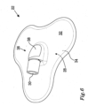
- the implementation of the fluid communication assembly 20 illustrated in Fig. 1 comprises two conduits, viz a first conduit 24' and a second conduit 24". Embodiments in which only one conduit is provided are also contemplated, see e.g. the embodiment of the suction device 22 illustrated in Fig. 6 .
- the conduit assembly 24 is adapted to provide a fluid communication between the wound therapy system 10 and the suction device 22.
- the Fig. 1 negative pressure wound therapy system 10 is adapted to apply a negative pressure to the volume at least partially enclosed by the wound cover member 18 through the first conduit 24'.
- the second conduit 24" may be used for introducing an air volume (e.g., ambient air, re-circulated air from the system) at a pressure level that is larger than the pressure level provided by the negative pressure source 12 into the volume least partially enclosed by the wound cover member 18.
- an air volume e.g., ambient air, re-circulated air from the system
- a purpose of introducing the air volume can be, for example, to monitor and/or dissolve a blockage or obstruction that could possibly occur in the first conduit 24'.
- the negative pressure wound therapy system 10 may preferably comprise a dosing feeder (not shown) adapted to feed a volume of air into the volume at least partially enclosed by the wound cover member 18 upon request by an operator and/or on a regular basis.
- the pressure of the air volume introduce via the second conduit 24" may be an atmospheric pressure.
- the dosing feeder may comprise a valve (not shown) located in or on the negative pressure source 12.
- the wound cover member 18 comprises a wound cover member opening 26 allowing a fluid passage through the wound cover member 18.
- the wound cover member opening 26 may be pre-cut in the wound cover member 18.
- the wound cover member opening 26 may be obtained after the wound cover member 18 has been arranged over the wound filler 16.
- the wound cover member opening 26 may be cut by a cutting tool such as a knife or a scalpel.
- the suction device 22 comprises a fluid inlet 28 and a fluid outlet 30.
- the fluid inlet 28 covers the wound cover member opening 26.
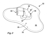
- Fig. 2 illustrates an embodiment of the suction device 22 according to the present invention.
- the suction device comprises an attachment portion 32 adapted to be attached to the wound cover member 18 of the negative pressure wound therapy system 10.
- the attachment portion 32 may comprise an adhesive layer 34 adapted to be attached to the wound cover member (not shown in Fig. 2 ).
- the Fig. 2 suction device 22 comprises a fluid inlet 28 being at least partially circumscribed by the attachment portion 32.
- the fluid inlet 28 is completely circumscribed by the attachment portion 32.
- Fig. 2 further illustrates that the suction device 22 also comprises a fluid outlet 30.
- the fluid outlet 30 is adapted to be in fluid communication with the negative pressure source 12.
- the fluid outlet 30 may be fluid communication with the negative pressure source 12 via the above discussed conduit assembly 24.
- the suction device 22 further comprises a connection portion 36 adapted to, at least during one operation condition of the suction device 22, provide a fluid communication between the fluid inlet 28 and the fluid outlet 30.
- the connection portion 36 is adapted to provide a permanent fluid communication between the fluid inlet 28 and the fluid outlet 30.
- connection portion 36 comprises an inspection portion 38.
- the inspection portion 38 is transparent to thereby enable that at least a portion of the fluid inlet 28 can be viewed through the inspection portion 38.
- the inspection portion 38 is relatively clear such that it, from the outside of the inspection portion 38, is possible to identify the position of the wound cover member opening (not shown in Fig. 2 ).
- the inspection portion may have a haze measure that is equal to or less than 50%.
- the haze measure may be equal to or less than any one of the following upper limits: 45%, 40%, 35%, 30% and 25%.
- the haze measure may be equal to or less than 32%.
- the inspection portion 38 may preferably have a total light transmittance of at least 50%, alternatively at least 60%. As another option, the total light transmittance may be at least 70%.
- Example 1 The definition of the haze measure and the total light transmittance, as well as a test method for obtaining a measured value thereof, is presented in Example 1 hereinbelow.
- the above discussed properties of the inspection portion 38 i.e. the haze measure and possibly also the total light transmittance, may be obtained in a plurality of ways.
- the material of the inspection portion 38 may be different from the material of the attachment portion 32.
- the inspection portion 38 may be made of polyurethane. Moreover, the inspection portion 38 may have a thickness that is within the range of 0.2 to 1.5 mm, alternatively within the range of 0.4 to 1.0 mm. As another non-limiting example, the thickness of the inspection portion 38 may be within the range of 0.7 to 0.9 mm.
- the inspection portion 38 may have a surface roughness, when using a measure that is the average angle of surface slopes S dq , that is less than or equal to S dq 20°.
- the inspection portion 38 may have a surface roughness that is less than or equal to S dq 17°.
- the inspection portion 38 may have a surface roughness, when using a surface roughness measure that is the percentage of increased area compared to a plane S dr , that is less than or equal to S dr 5%.
- the inspection portion 38 may have a surface roughness that is less than or equal to S dr 3.5%.
- an implementation of the inspection portion 38 may have a surface roughness that is less than or equal to S dq 20° as well as less than or equal to S dr 5%.
- an implementation of the inspection portion 38 has a surface roughness, when measured as the average deviation from average surface plane S a , that is less than or equal to 1500 nm. It is further envisaged that implementations of the inspection portion have a surface roughness measure S a that is less than or equal to 1500 nm in addition to a surface roughness measure of S dq less than or equal to 20° and/or a surface roughness measure of S dr less than or equal to 5%.
- Example 3 Examples of surface roughness data for an embodiment of a suction device 22 is presented in Example 3 hereinbelow.
- the inspection portion 38 is delimited by an inner surface 38' and an outer surface 38".
- the inner surface 38' is located closer to the fluid inlet 28 than the outer surface 38".
- At least the outer surface 38" has a surface roughness measure within any one of the above discussed surface measure roughness limits, viz the measure that is the average angle of surface slopes S dq and/or the measure that is the percentage of increased area compared to a plane S dr and/or the measure that is the average deviation from average surface plane S a .
- the inner surface 38' may be sufficiently smooth such that the inspection portion 38 provides appropriate transparency characteristics.
- the inner surface 38' may have a surface roughness measure that corresponds to the surface measure limits of the outer surface 38".
- each one of the inner surface 38' and the outer surface 38" has a surface roughness measure within any one of the above discussed limits.
- the attachment portion 32 and the connection portion 36, including the inspection portion 38, of the suction device 22 may form a unitary component.
- both the attachment portion 32 and the connection portion 36 may be made of polyurethane.
- the entire suction device 22 is made of polyurethane.
- at least a portion of the suction device 22 may be made of at least one of the following materials: other types of urethanes, silicone, transparent hydrocolloid, PVC, hydrogel, copolyester, polyethylene, TPS (thermoplastic elastomers based on styrene) or TPO (thermoplastic olefins) i.e. blends of polyethylenes and polypropylenes.
- the suction device 22 may be flexible. This may be achieved by for instance making at least portions of the suction device 22 of one or more flexible materials, such as polyurethane, silicone, transparent hydrocolloid, soft PVC, hydrogel, copolyester, polyethylene.
- flexible materials such as polyurethane, silicone, transparent hydrocolloid, soft PVC, hydrogel, copolyester, polyethylene.
- embodiments of the suction device 22 may comprise one or more additional portions that is/are transparent.
- such portions may have one or more of the transparency indicative characteristics, such as at least one of the following: the haze measure, the total light transmittance, the material, the thickness and the surface roughness, that have been discussed hereinabove.
- an embodiment of the suction device is envisaged wherein substantially the entire suction device is transparent (not shown).
- the inspection portion 38 of a suction device 22 in which the attachment portion 32 and the connection portion 36 form a unitary component may have a thickness that is within the range of 1.5 to 0.2 mm, alternatively within the range of 1.0 to 0.4 mm. As another alternative, the thickness may be within the range of 0.7 to 0.9 mm.
- the inspection portion 38 may have a surface area of at least 10 mm 2 .
- the inspection portion 38 has a total surface area of at least 15 mm 2 , at least 25 mm 2 , at least 50 mm 2 or at least 70 mm 2 .
- the inspection portion may have a total surface area that is equal to or less than or equal to 100 mm 2 , alternatively less than or equal to 80 mm 2 .
- the portion of the suction device 22 that encloses the inspection portion 38 may be less transparent than the inspection portion 38.
- the haze measure of the portion of the suction device 22 that encloses the inspection portion 38 may be higher than the haze measure of the inspection portion 38.
- the inspection portion 38 may be a continuous portion.
- the inspection portion 38 may be discontinuous, i.e. comprising two or more sub-portions.
- the one or more sub-portions may for example be separated from one another by one or more portions with a relatively low transparency of the connection portion 36.
- the inspection portion 38 may be configured so as to have a magnifying effect such that at least a portion of the fluid inlet 28, when looked upon through the inspection portion 38, is magnified by the inspection portion 38.
- FIG. 2 An implementation of such an inspection portion is illustrated in Fig. 2 wherein at least the outer surface 38" has a convex shape.
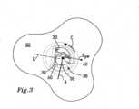
- Fig. 3 is a bottom view of the Fig. 2 embodiment of the suction device 22.
- Fig. 3 illustrates that the connection portion 36 may comprise a duct wall 40 at least partially defining a connection duct from the fluid inlet 28 to the fluid outlet 30.
- the duct wall 40 comprises the inspection portion 38.
- the connection portion 36 comprises a partition wall 42 extending at least partially from the duct wall 40.
- the partition wall 42 may be of a different material than the duct wall 40.
- the partition wall 42 and the duct wall 40 form a unitary component.
- FIG. 3 illustrates an embodiment of the suction device wherein the fluid outlet 30 extends in a longitudinal direction L and the partition wall 42 extends in a partition wall extension E PW that is substantially parallel to the longitudinal direction L.
- the thickness of the partition wall 42 may be within the range of 0.4 to 1.0 mm. As another example, the thickness may be within the range of 0.5 to 0.8 mm.
- Fig. 3 further illustrates that the inlet may extend in a circumferential direction C. Moreover, the fluid inlet also extends in an axial direction A which is substantially perpendicular to the circumferential direction C. Purely by way of example, a projection of at least a portion of the partition wall 42, in the axial direction A and towards the fluid inlet 28, is located within the fluid inlet 28. The above discussed position of at least a portion of the partition wall 42 may reduce the risk of introducing flaps from the wound cover member (not shown in Fig. 3 ) into the fluid outlet 30.
- the suction device 22 may be manufactured by injection moulding wherein a curable material is injected into a mould.
- the curable material may comprise polyurethane.
- at least 80% of the curable material consists of polyurethane.
- the inspection portion 38 may be post-treated such that the desired see-through characteristic of the inspection portion is obtained.
- the inspection portion 38 may be polished such that the surface roughness within any one of the above discussed limits may be obtained on the outer surfaces delimiting the inspection portion 38.
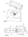
- Fig. 4 illustrates a mould 44 that may be used in an embodiment of a method for producing a suction device for a negative pressure wound therapy system.
- the mould 44 comprises a mould cavity 46, the walls 48 of which mirror the shape of the suction device to be manufactured.
- the mould 44 further comprises a mould core 49 adapted to be introduced into the mould cavity 46.
- Fig. 4 illustrates that the mould cavity wall 48 comprises a mould inspection portion 50 that corresponds to the inspection portion 38 of the suction device 22.
- the mould inspection portion 50 has a surface roughness that is lower than a surface roughness of the portion of the cavity wall which encloses the mould inspection portion 50.
- the surface roughness of the mould inspection portion 50 may be less than or equal to half the surface roughness of the portion of the cavity wall which encloses the mould inspection portion 50.
- the mould inspection portion 50 has a surface roughness, when using a surface roughness measure that is the average angle of surface slopes S dq , of less than or equal to S dq 15°.
- the mould inspection portion 50 could have a surface roughness, when using a surface roughness measure that is the percentage of increased area compared to a plane S dr , of less than or equal to S dr 4 %.
- the surface roughness of the mould inspection portion 50 may be less than or equal to S dr 3.5 %.
- an implementation of mould inspection portion 50 may have a surface roughness, when measured as the average deviation from average surface plane S a , that is less than or equal to 1500 nm.
- an implementation of the mould inspection portion 50 may have a surface roughness measure of S a less than or equal to 1500 nm in addition to a surface roughness measure less than or equal to S dq 15° and/or a surface roughness measure less than or equal to S dr 4%.
- an appropriate surface roughness of the mould inspection portion 50 may be achieved by polishing the mould inspection portion 50 using a diamond paste with particles the size of which are 1 micron or less.
- an appropriately low surface roughness, and consequently appropriate see-through characteristic may be obtained for the inspection portion 38 of the suction device 22 thus produced.
- the above discussed see-through characteristic may for instance be obtained without the need of any post-treatment of the inspection portion 38.
- At least 50% of the mould cavity wall that is located outside of the mould inspection portion may for instance have a surface roughness greater than S a 1500 nm.
- the relatively large surface roughness of a relatively large portion of the mould cavity wall implies that the cast mould, once cured, can be released from the mould 44 in a straightforward way.
- the mould core 49 may also have a surface roughness, at least in a mould core inspection portion 51 that corresponds to the inspection portion 38 of the suction device 22, of less than or equal to S dq 15°.
- the mould core inspection portion 51 could have a surface roughness of less than or equal to S dr 4 %.
- the surface roughness of the mould core inspection portion 51 may be less than or equal to S dr 3.5 %.
- a relatively large portion, e.g. more than 50%, of the area of the portion of the mould core 49 that is located outside the mould core inspection portion 51 may have a surface roughness of more than S dq 15°, alternatively of more than S dr 4 %.
- test method proposed hereinbelow may be used.
- the below test method generally follows the test procedure as presented in ASTM D1003, procedure B.
- the test procedure is illustrated in Fig. 5 .
- the instrument used for the test method is preferably a Perkin Elmer Lambda 9 UV-Vis-NIR spectrophotometer 52 equipped with an integrating sphere 54.
- the diameter of the sphere is 6 cm.
- a photomultiplier detector 56 is located inside the sphere and protected from direct light by a baffle.
- the geometry used is unidirectional illumination with diffuse viewing.
- a suction device should be tested in the condition that it is intended to assume when the suction device is to be attached to a wound cover member. As such, if the suction device is to be sterilized in a certain manner prior to being attached to the wound cover member, the suction device should consequently be sterilized in the same manner prior to being subjected to the haze measure and/or total light transmittance measurements that are presented hereinbelow.
- Typical methods used to sterilize a suction device may comprise ethylene oxide gas sterilization, gas plasma technology, steam sterilization, gamma irradiation, and electron beam irradiation. If there is no specific sterilization method associated with a suction device, the sterilization method as outlined in Example 2 hereinbelow could be employed.
- a deviation from the ASTM D1003, procedure B, standard is occasioned by the fact that the size of the inspection portion of a suction device may be smaller than the size of the entrance port 58 of the sphere.
- a lens 60 is placed between the light source 62 (including the monochromator) and the sphere 54.
- Fig. 5 further illustrates a sample 59 positioned adjacent to the entrance port 58.
- the lens is a convex lens with a focal distance of 8 cm.
- the distance between the lens and the sample is 4 cm and the distance between the lens and the light source is approximately 1 m.
- the lens 60 limits the illuminated area at the entrance port 58 of the sphere to a square shaped area of approximately 4 mm 2 .
- the incident light reaches the sample surface at an angle of 8° to the normal direction of the sample surface.
- the angle of 8° is set by the sphere manufacturer since the sphere is also intended to be used for reflection measurements.
- the entrance port 58 is covered with a circular aperture with a diameter of 2 mm.
- the focus of the lens 60 is, however, not located at the entrance port, but inside the sphere 54. This means that an undisturbed light beam, i.e., when there is no sample at the entrance port 58, will diverge after passing the focus of the lens and illuminate a circular area, due to the circular aperture at the entrance port, with a diameter of approximately 7 mm at the exit port 62.
- the size of the square shaped exit port 62 is 1 cm 2 . Light passing through the entrance aperture will fall on the exit port 62 only and not on the sphere wall 64 when no sample was placed at the entrance. A light trap at the exit port 62 will absorb all light entering the sphere 54.
- Spectra are obtained between 300 and 800 nm, i.e. the spectra covers the visible region between 380 and 780 nm.
- Total transmission spectra are acquired with a highly and diffusively reflecting Spectralon reference at the exit port 62.
- Diffusively scattered spectra were acquired with a light trap at the exit port 62.
- the total light transmittance is defined as ⁇ Total .
- Haze measure ⁇ Diffuse ⁇ Total
- total and ⁇ Diffuse are defined by and calculated according to eq. 1 above.
- a sample is examined twice and the haze measure is calculated as the average value of the haze measures obtained from the two examinations.
- a suction device according to the invention and as depicted in Figs. 2 and 3 was made of polyurethane and its properties tested according to that method that is outlined above.
- the total light transmittance as well as the haze measure was measured for the attachment portion 32 as well as the inspection portion 38 of the tested suction device.
- the results of the measurements are presented hereinbelow: Tested area ⁇ Total (%) Haze measure (%) Attachment portion 85 79 Inspection portion 73 32
- Sterilization in accordance with sterigenics cycle 38 may be used for the sterilization of a suction device.
- the cycle settings for a sterigenics cycle 38 are presented hereinbelow.
- Parameter Unit Sterigenics cycle 38 Jacket temp °C 38 Evacuation pressure mbar 255 Evacuation time hh:mm 01:00 Pre Humidification mbar - Pre Humidification hh:mm - Leak Rate mbar/ minutes 15 mbar/10 min
- First Nitrogen injection (final pressure) 345 Eo Injection temperature °C >20
- Eo Dwell time hh:mm 04:00 Estimated Gas concentration mg/l 650-750 Temperature during Eo Dwell °C 40 Chamber Pressure during Dwell mbar 790
- Eo Evacuation Pressure mbar 250 E
- pre humidification is used on Sterigenics cycles, usually 12-24 hours, temperature degree of 40 Celsius and humidity >60 RH %.
- aeration room is used on Sterigenics cycles, usually 96 hours, 40 degree of Celcius.
- a suction device according to the invention and as depicted in Figs. 2 and 3 was made of polyurethane and its properties tested according to methods outlined in Example 1.
- the inspection portion of this device had a haze measure of approximately 32 % and total transmittance value of approximately 73 %.
- the surface roughness of the inspection portion of three individual suction device samples where determined using the following area surface roughness measures: S a (average deviation from average surface plane), S dq (average angle of surface slopes) as well as S dr (percentage of increased area compared to a plane). Moreover, the surface roughness of the attachment portion of one of the samples was measured. Each one of the above area surface roughness measures was determined in accordance with the following standards: ISO 25178 -2:2009 and ISO 25178-3:2009.
- Each one of the suction device samples was produced by a method for producing a suction device in accordance with the present disclosure, i.e. using a mould with a relatively smooth mould inspection portion 50.
- the surface roughness of the mould inspection portion 50 of the mould that was used for producing the suction device samples is presented hereinbelow.
- Example 2 Each one of the three individual samples was sterilized in accordance with the sterilization procedure outlined in Example 2 hereinabove prior to the surface roughness measurements.
- the surface roughness was measured for a mould 48 with a mould inspection portion 50 as illustrated in Fig. 4 .
- the mould inspection portion 50 was polished using a diamond paste with particles the size of which are 1 micron.
- a suction device according to the invention and as depicted in Figs. 2 and 3 was made of polyurethane and its properties tested according to methods outlined in Examples 1 and 3.
- This device had a haze measure of approximately 32%, total transmittance value of approximately 73 %, and surface roughness of S dq 17° at the outer surface 38" of the inspection portion 38.
- the thickness of the device in the inspection portion 38 was between 0.7 mm and 0.9 mm.
- the device comprised a partition wall 42 underneath the inspection portion 38.
- the inspection portion 38 was separated by the partition wall 42 and the surface area of one of the inspection sub portions was approximately 40 mm 2 and the surface are of the other inspection sub portion was approximately 32 mm 2 .
- the device was adhered to a flat surface by an adhesive and was connected to a negative pressure source via the device's fluid outlet.
- a pump was used as the negative pressure source. Negative pressure was applied at -200 mm Hg for 2 hours. No collapse or indentation of the device at the inspection portion was observed during the time in which negative pressure was applied. Thus, the integrity of the device was maintained under negative pressure.
Description
- The present disclosure relates to a suction device. Moreover, the present disclosure relates to a method for producing a suction device.
- Some types of wounds are advantageously treated by so called negative pressure wound therapy. In the field of negative pressure wound therapy, a negative pressure is applied to the wound for a relatively long time and it has been realized that the healing process may be expedited by using such a wound therapy.
- To this end, a negative pressure wound therapy system may be used which generally comprises a wound cover member that is adapted to be placed over a wound. The system further generally comprises a negative pressure source, such as a vacuum pump, which is in fluid communication with the wound cover member via a fluid communication assembly that comprises a suction device.
- For instance,
WO99/13793 WO99/13793 - Alternatively, the suction device may be adapted to be attached to the outside of the wound cover member, for instance by means of an adhesive layer located on the suction device, such that a fluid inlet of the suction device is in fluid communication with an opening in the wound cover member.
- In order to obtain an appropriate fluid communication between the suction device's fluid inlet and the wound cover member opening, it is generally desired that the fluid inlet of the suction device be placed over the wound cover member opening. The operation of correctly attaching the suction device to the wound cover member may be cumbersome.
- According to its abstract,
US2012/010578 A1 discloses systems, devices, and methods enabling treatment (e.g., debridement) of wounds with liquid, gas, or particles in a non-controlled setting while providing containment of contaminated liquid, gas or particles, thereby preventing exposure of individuals and surfaces in proximity to the patient to infectious materials. In certain embodiments, the systems and devices are conformable to the contours of a non-planar surface, such as the human body (e.g., to seal or partially seal the device or system to a portion of a human body). - According to its abstract,
US 4 778 446 A discloses a semi-rigid cylindrical open hollow open-ended collar mounted to an adhesive label by a flexible sheet. -
GB 1 549 756 A - According to its abstract,
US2008/275409 A1 discloses methods and devices transmit micromechanical forces locally on the millimetre to micron scale for promoting wound healing. Micromechanical forces can selectively be applied directly to tissue, in some embodiments, by using micro chambers fluidically connected to micro channels. Each chamber, or in some cases, group of chambers, may be associated with a valve to control vacuum pressure, positive pressure, liquid delivery, and/or liquid removal from each chamber or group of chambers. - According to its abstract, in
US2006/173253 A1 , wound fluid blood detection systems and methods are described that are operable in conjunction with reduced pressure wound treatment (RPWT) systems, as well as ancillary therapy and monitoring systems applied concurrently with RPWT systems. The blood detection monitor operates by optically characterizing the content of wound fluids to the extent of identifying percentage blood content. This identification relies upon the transmission of select wavelengths of light across a volume of wound fluid to a photo detector (connected to signal processing instrumentation) capable of quantifying the absorption characteristics of the fluid. - One object of the present disclosure is to provide a suction device for a negative pressure wound therapy system, which suction device facilitates the placement thereof relative to a wound cover member opening of the negative pressure wound therapy system.
- This object is achieved by a suction device according to
claim 1. - As such, the present disclosure relates to a suction device. The suction device comprises an attachment portion adapted to be attached to a wound cover member. The suction device comprises a fluid inlet being at least partially circumscribed by the attachment portion. The suction device also comprises a fluid outlet and the suction device further comprises a connection portion adapted to, at least during one operation condition of the suction device, provide a fluid communication between the fluid inlet and the fluid outlet.
- Purely by way of example, the suction device may be suitable for a negative pressure wound therapy system. Moreover, although purely by way of example, the wound cover member may form a part of the negative pressure wound therapy system.
- The connection portion comprises an inspection portion that is transparent to thereby facilitate the positioning of the suction device relative to the wound cover member.
- The fact that the inspection portion is transparent implies that an operator, striving to attach the suction device to the wound cover member, will experience a possibility to see the wound cover member opening, or at least a marker of the wound cover member indicative of the position of the wound cover member opening, through the inspection portion.
- Such a possibility in turn implies that the operator may be able to place the suction device at a position on the wound cover member in which the fluid inlet of the suction device is located above the wound cover member opening.
- Moreover, by virtue of the fact that the inspection portion is transparent, it may be possible to monitor exudates that are transferred from the wound cover member towards the negative pressure source via the suction device.
- Optionally, the inspection portion has a haze measure that is equal to or less than 50%.
- The definition of the haze measure, as well as a test method for obtaining a measured value thereof, is presented in Example 1 hereinbelow. A haze measure equal to or below the above limit implies that an appropriate transparency may be obtained for the inspection portion.
- Alternatively, the haze measure may be equal to or less than any one of the following upper limits: 45%, 40%, 35%, 30%, 25% and 20%. As another option, the haze measure may be equal to or less than 32%.
- Optionally, the inspection portion has a total light transmittance of at least 50%. As another option, the inspection portion has a total light transmittance of at least 60%. Optionally, the inspection portion has a total light transmittance of at least 70%.
- The definition of total light transmittance, as well as a test method for obtaining a measured value thereof, is presented in Example 1 hereinbelow.
- The provision of a total light transmittance equal to or more than at least one of the above limits implies that it may be possible to see the wound cover member opening, or at least a marker of the wound cover member indicative of the position of the wound cover member opening, through the inspection portion even if the process of attaching the suction device to the wound cover member is performed in a condition with relatively low illumination.
- Optionally, the inspection portion may have a surface roughness, when using a surface roughness measure that is the average angle of surface slopes Sdq, that is less than or equal to
S dq 20°. The feature that the surface roughness is less than or equal toS dq 20° implies that an appropriate transparency may be obtained for the inspection portion. Alternatively, the inspection portion may have a surface roughness that is less than or equal to Sdq 17°. - Optionally, the inspection portion may have a surface roughness, when using a measure that is the percentage of increased area compared to a plane Sdr, that is less than or equal to Sdr 5%. The feature that the surface roughness that is less than or equal to Sdr 5% implies that an appropriate transparency may be obtained for the inspection portion. Alternatively, the inspection portion may have a surface roughness that is less than or equal to Sdr 3.5%.
- Optionally, the inspection portion may have a surface roughness, when using a measure that is the average deviation from average surface plane Sa, that is less than or equal to Sa 1500 nm. Alternatively, the surface roughness of the inspection portion may be equal to or less than any one of the following upper limits: 1400 nm, 1300 nm and 1200 nm.
- Optionally, the inspection portion is delimited by an inner surface and an outer surface, the inner surface being located closer to the fluid inlet than the outer surface. Optionally, at least the outer surface of the inspection portion has a surface roughness measure within any one of the above discussed limits. As another option, each one of the inner surface and the outer surface has a surface roughness measure within any one of the above discussed limits.
- Optionally, the inspection portion has a thickness within the range of 0.2 to 1.5 mm, alternatively within the range of 0.4 to 1.0 mm. As another example, the inspection portion has a thickness within the range of 0.7 to 0.9 mm. The inspection portion thickness within any one of the above discussed ranges may have the advantage of enabling appropriate see-through characteristics of the inspection portion and also providing an inspection portion that has an appropriately low risk of collapsing when a negative pressure is applied to the negative pressure wound therapy system.
- Optionally, the inspection portion is made of polyurethane.
- Optionally, the inspection portion has a total surface area of at least 10 mm2. As other examples, the inspection portion has a total surface area of at least 15 mm2, at least 25 mm2, at least 50 mm2 or at least 70 mm2. A surface area of the inspection portion equal to or above any one of the above limits implies an appropriately large field of view for the operator.
- Optionally, the inspection portion may have a total surface area that is equal to or less than 100 mm2, alternatively less than or equal to 80 mm2. A surface area of the inspection portion equal to or below any one of the above limits implies that an operator will be able to view only a relatively limited area of the wound cover member through the inspection portion and this in turn implies that the operator may be able to determine, with a relatively high degree of certainty, whether or not the inspection portion aligns with the wound cover member opening.
- Optionally, the inspection portion is a continuous portion. The feature that the inspection portion is a continuous portion implies that the operator will have a sufficiently unobscured view through the inspection portion towards the wound cover membrane. As another option, the inspection portion may be discontinuous, i.e. comprising two or more sub-portions. The one or more sub-portions may for example be separated from one another by portions with a relatively low transparency of the connection portion. As a non-limiting example, an inspection portion may comprise two sub-portions each one of which having a surface area of at least 20 mm2. As another non-limiting example, the two sub-portions may have different surface areas and a first sub-portion may have a surface area of at least 30 mm2 and a second sub-portion may have a surface area of at least 40 mm2.
- Optionally, the inspection portion is configured so as to have a magnifying effect such that at least a portion of the fluid inlet, when looked upon through the inspection portion, is magnified by the inspection portion. Such a magnifying effect of the inspection portion may facilitate the placing of the suction device in an appropriate position on the wound cover member.
- Optionally, the inspection portion is delimited by an inner surface and an outer surface, the inner surface being located closer to the fluid inlet than the outer surface. At least the outer surface has convex shape.
- The connection portion comprises a duct wall at least partially defining a connection duct from the inlet to the outlet. The duct wall comprises the inspection portion, the connection portion comprising a partition wall extending at least partially from the duct wall.
- By virtue of the presence of the partition wall, the risk of having the connection portion collapse, e.g. during an installation procedure and/or during a negative pressure therapy, is reduced. As such, the presence of the partition wall implies that the connection portion may substantially maintain its intended shape during at least an installation procedure.
- This in turn implies that an appropriate field of view will be obtained through the inspection portion. Moreover, the presence of the partition wall implies that the wall thickness of the inspection portion can be reduced, while still obtaining appropriate structural characteristics of the connection portion. The above discussed thickness reduction generally implies improved see-through characteristics of the inspection portion.
- Optionally, the fluid outlet extends in a longitudinal direction and the partition wall extends in a partition wall extension that is substantially parallel to the longitudinal direction. The above orientation of the partition wall in relation to the extension of the fluid outlet implies that a reinforcement of the connection portion is obtained, which reinforcement will have a limited negative influence on the flow between the suction device's inlet and its fluid outlet.
- As used herein, the expression "substantially parallel" means that a first vector, extending in the longitudinal direction, and a second vector, extending in the partition wall extension, intersect one another at an angle that is equal to or less than 30°.
- The inlet extends in a circumferential direction, the inlet further extending in an axial direction being substantially perpendicular to the circumferential direction, wherein a projection of at least a portion of the partition wall, in the axial direction and towards the inlet, is located within the inlet. By virtue of the fact that at least a portion of the partition wall is located within the inlet, the risk of having the connection portion collapse may be further reduced. Moreover, the feature that a portion of the partition wall is located within the inlet implies a reduced risk of having e.g. wound cover member flaps transported through the suction device.
- A second aspect of the present disclosure relates to a kit for a negative pressure wound therapy system. The kit comprises:
- a suction device according to the first aspect of the present disclosure, and
- a wound cover member adapted to be attached over a wound.
- Optionally, the wound cover member comprises a wound cover film.
- Optionally, the kit further comprises fluid communication means adapted to provide a fluid communication between the fluid outlet and a negative pressure source.
- A third aspect of the present disclosure relates to a method for producing a suction device according to
claim 12. The suction device comprises an attachment portion adapted to be attached to a wound cover member. The suction device comprises a fluid inlet being at least partially circumscribed by the attachment portion. The suction device also comprises a fluid outlet and the suction device further comprises a connection portion adapted to, at least during one operation condition of the suction device, provide a fluid communication between the fluid inlet and the fluid outlet. The connection portion comprises an inspection portion. - The method comprises:
- providing a mould for the suction device, the mould comprising a mould inspection portion corresponding to the inspection portion of the connection portion, the mould inspection portion having a surface roughness, when using a surface roughness measure that is the average angle of surface slopes Sdq, less than or equal to Sdq 15°, and
- injecting a curable material into the mould.
- Purely by way of example, the suction device produced in accordance with the above discussed method may be suitable for a negative pressure wound therapy system. Moreover, although purely by way of example, the wound cover member may form a part of the negative pressure wound therapy system.
- Optionally, the mould inspection portion may have a surface roughness, when using a measure that is the percentage of increased area compared to a plane Sdr, that is less than or equal to Sdr 4 %. As another alternative, the surface roughness of the mould inspection portion may be less than or equal to Sdr 3.5 %.
- Optionally, the curable material comprises polyurethane.
- A fourth aspect of the present disclosure relates to a method comprising:
- providing a cover member,
- providing a suction device comprising
- i. an attachment portion for attachment to the cover member,
- ii. a fluid inlet at least partially circumscribed by the attachment portion,
- iii. a fluid outlet,
- iv. a connection portion that allows fluid communication between the fluid inlet and fluid outlet, wherein the connection portion comprises an inspection portion that is transparent,
- providing the cover member with an opening,
- positioning the suction device such that the fluid inlet aligns with the opening in the cover member.
- Optionally, the above method further comprises applying suction to the suction device,
- With reference to the appended drawings, below follows a more detailed description of embodiments of the invention cited as examples.
- In the drawings:
- Fig. 1
- illustrates an embodiment of a negative pressure wound therapy system;
- Fig. 2
- illustrates a perspective view of an embodiment of a suction device;
- Fig. 3
- illustrates a bottom view of the
Fig. 2 embodiment; - Fig. 4
- illustrates a mould suitable for moulding a suction device;
- Fig. 5
- illustrates a test method for determining the haze measure of an object, and
- Fig. 6
- illustrates a perspective view of another embodiment of a suction device.
- It should be noted that the appended drawings are not necessarily drawn to scale and that the dimensions of some features of the present invention may have been exaggerated for the sake of clarity.
- Haze measure: As used herein, the phrase "haze measure" (also known as "haze value" or "transmission haze") refers to its ordinary meaning in the art, and describes the amount of light that is scattered as it passes through a material. As used herein, the "haze measure" is calculated as the ratio of diffuse light transmittance over total light transmittance. (See Equation 2 in Example 1 hereinbelow)
- Surface roughness: As used herein, the term "surface roughness" refers to its ordinary meaning in the art, and provides a measure of the texture of a surface based on vertical deviations of a surface from its ideal form.
- In particular the area surface roughness parameters Sa (average deviation from average surface plane), Sdq (average angle of surface slopes) as well as Sdr (percentage of increased area compared to a plane) may be determined in accordance with the following standards: ISO 25178 -2:2009 and ISO 25178-3:2009. See also Example 3 hereinbelow.
- Inspection portion: As used herein, the phrase "inspection portion" (also referred to as "inspection window") refers to a portion that is characterized by optical properties that allow, for example, a user or an optical device, using light in the visible light spectrum, to see through to the other side of the inspection portion. The inspection portion may be one continuous portion. Alternatively, the inspection portion may be comprised of more than one part. In embodiments in which the inspection portion is comprised of more than one part, the more than one part(s) may be equal or unequal in surface area to each other.
- The invention will, in the following, be exemplified by embodiments. It is to be understood, however, that the embodiments are included in order to explain principles of the invention and not to limit the scope of the invention defined by the appended claims.
-
Fig. 1 illustrates a negative pressurewound therapy system 10. The purpose of the negative pressurewound therapy system 10 is to obtain a negative pressure in the area of a wound 11. - The negative pressure system illustrated in
Fig. 1 comprises anegative pressure source 12, which inFig. 1 is implemented as a vacuum pump. Moreover,Fig. 1 illustrates that thesystem 10 comprises awound cover assembly 14. - The implementation of the
wound cover assembly 14 illustrated inFig. 1 comprises awound filler 16 which is adapted to be placed on or in the wound to be treated by the negative pressure wound therapy. Purely by way of example, thewound filler 16 may comprise an absorbent material, such as open-celled foam material. As a non-limiting example, thewound filler 16 may comprise a flexible open-celled foam material, such as a sponge material. Moreover, theFig. 1 implementation of thewound cover assembly 14 comprises awound cover member 18 adapted to cover thewound filler 16. - The
wound cover member 18 is generally adapted to be attached to the skin surrounding the wound. Purely by way of example, thewound cover member 18 may comprise a wound cover film. Thewound cover member 18 may preferably be attached to the skin by an adhesive. Examples of adhesives that may be used include, but are not limited to, acrylic adhesives and/or silicone gel adhesives. In some embodiments, the adhesive or adhesives is/are already incorporated as part of the wound cover film. In some embodiments, the adhesive or adhesives is/are applied to the wound cover member during use. Purely by way of example, the adhesive sold under the trademark Mepiseal® by Mölnlycke Healthcare AB may be used for attaching the wound cover member to the skin surrounding the wound. -
Fig. 1 further illustrates that the negative pressurewound therapy system 10 comprises afluid communication assembly 20 adapted to provide a fluid communication between thenegative pressure source 12 and thewound cover member 18. - The
fluid communication assembly 20 may preferably comprise asuction device 22 and aconduit assembly 24 comprising one or more conduits. The implementation of thefluid communication assembly 20 illustrated inFig. 1 comprises two conduits, viz a first conduit 24' and asecond conduit 24". Embodiments in which only one conduit is provided are also contemplated, see e.g. the embodiment of thesuction device 22 illustrated inFig. 6 . Theconduit assembly 24 is adapted to provide a fluid communication between thewound therapy system 10 and thesuction device 22. - The
Fig. 1 negative pressurewound therapy system 10 is adapted to apply a negative pressure to the volume at least partially enclosed by thewound cover member 18 through the first conduit 24'. In embodiments in which a second conduit is provided, thesecond conduit 24" may be used for introducing an air volume (e.g., ambient air, re-circulated air from the system) at a pressure level that is larger than the pressure level provided by thenegative pressure source 12 into the volume least partially enclosed by thewound cover member 18. - A purpose of introducing the air volume can be, for example, to monitor and/or dissolve a blockage or obstruction that could possibly occur in the first conduit 24'. Purely by way of example, the negative pressure
wound therapy system 10 may preferably comprise a dosing feeder (not shown) adapted to feed a volume of air into the volume at least partially enclosed by thewound cover member 18 upon request by an operator and/or on a regular basis. As a non-limiting example, the pressure of the air volume introduce via thesecond conduit 24" may be an atmospheric pressure. Purely by way of example, the dosing feeder may comprise a valve (not shown) located in or on thenegative pressure source 12. - The
wound cover member 18 comprises a wound cover member opening 26 allowing a fluid passage through thewound cover member 18. Purely by way of example, the wound cover member opening 26 may be pre-cut in thewound cover member 18. As another non-limiting example, the wound cover member opening 26 may be obtained after thewound cover member 18 has been arranged over thewound filler 16. For instance, the wound cover member opening 26 may be cut by a cutting tool such as a knife or a scalpel. - The
suction device 22 comprises afluid inlet 28 and afluid outlet 30. In order to obtain the desired negative pressure in the area of a wound 11, it is generally desired that thefluid inlet 28 covers the wound cover member opening 26. -
Fig. 2 illustrates an embodiment of thesuction device 22 according to the present invention. The suction device comprises anattachment portion 32 adapted to be attached to thewound cover member 18 of the negative pressurewound therapy system 10. Purely by way of example, theattachment portion 32 may comprise anadhesive layer 34 adapted to be attached to the wound cover member (not shown inFig. 2 ). - Moreover, the
Fig. 2 suction device 22 comprises afluid inlet 28 being at least partially circumscribed by theattachment portion 32. In theFig. 2 embodiment of thesuction device 22, thefluid inlet 28 is completely circumscribed by theattachment portion 32. -
Fig. 2 further illustrates that thesuction device 22 also comprises afluid outlet 30. Thefluid outlet 30 is adapted to be in fluid communication with thenegative pressure source 12. Purely by way of example, thefluid outlet 30 may be fluid communication with thenegative pressure source 12 via the above discussedconduit assembly 24. - As may be gleaned from
Fig. 2 , thesuction device 22 further comprises aconnection portion 36 adapted to, at least during one operation condition of thesuction device 22, provide a fluid communication between thefluid inlet 28 and thefluid outlet 30. In theFig. 2 embodiment of thesuction device 22, theconnection portion 36 is adapted to provide a permanent fluid communication between thefluid inlet 28 and thefluid outlet 30. -
Fig. 2 further illustrates that theconnection portion 36 comprises aninspection portion 38. Theinspection portion 38 is transparent to thereby enable that at least a portion of thefluid inlet 28 can be viewed through theinspection portion 38. Thus, theinspection portion 38 is relatively clear such that it, from the outside of theinspection portion 38, is possible to identify the position of the wound cover member opening (not shown inFig. 2 ). - To this end, although purely by way of example, the inspection portion may have a haze measure that is equal to or less than 50%.
- Alternatively, the haze measure may be equal to or less than any one of the following upper limits: 45%, 40%, 35%, 30% and 25%. As another option, the haze measure may be equal to or less than 32%.
- Moreover, the
inspection portion 38 may preferably have a total light transmittance of at least 50%, alternatively at least 60%. As another option, the total light transmittance may be at least 70%. - The definition of the haze measure and the total light transmittance, as well as a test method for obtaining a measured value thereof, is presented in Example 1 hereinbelow.
- The above discussed properties of the
inspection portion 38, i.e. the haze measure and possibly also the total light transmittance, may be obtained in a plurality of ways. Purely by way of example, the material of theinspection portion 38 may be different from the material of theattachment portion 32. - As a non-limiting example, at least the
inspection portion 38 may be made of polyurethane. Moreover, theinspection portion 38 may have a thickness that is within the range of 0.2 to 1.5 mm, alternatively within the range of 0.4 to 1.0 mm. As another non-limiting example, the thickness of theinspection portion 38 may be within the range of 0.7 to 0.9 mm. - Furthermore, although purely by way of example, the
inspection portion 38 may have a surface roughness, when using a measure that is the average angle of surface slopes Sdq, that is less than or equal toS dq 20°. Alternatively, theinspection portion 38 may have a surface roughness that is less than or equal to Sdq 17°. - Optionally, although purely by way of example, the
inspection portion 38 may have a surface roughness, when using a surface roughness measure that is the percentage of increased area compared to a plane Sdr, that is less than or equal to Sdr 5%. Alternatively, theinspection portion 38 may have a surface roughness that is less than or equal to Sdr 3.5%. - As another non-limiting option, an implementation of the
inspection portion 38 may have a surface roughness that is less than or equal toS dq 20° as well as less than or equal to Sdr 5%. - Moreover, it is envisaged that an implementation of the
inspection portion 38 has a surface roughness, when measured as the average deviation from average surface plane Sa, that is less than or equal to 1500 nm. It is further envisaged that implementations of the inspection portion have a surface roughness measure Sa that is less than or equal to 1500 nm in addition to a surface roughness measure of Sdq less than or equal to 20° and/or a surface roughness measure of Sdr less than or equal to 5%. - Examples of surface roughness data for an embodiment of a
suction device 22 is presented in Example 3 hereinbelow. - In the
Fig. 2 implementation, theinspection portion 38 is delimited by an inner surface 38' and anouter surface 38". The inner surface 38' is located closer to thefluid inlet 28 than theouter surface 38". - According to an implementation of the
inspection portion 38, at least theouter surface 38" has a surface roughness measure within any one of the above discussed surface measure roughness limits, viz the measure that is the average angle of surface slopes Sdq and/or the measure that is the percentage of increased area compared to a plane Sdr and/or the measure that is the average deviation from average surface plane Sa. - Moreover, the inner surface 38' may be sufficiently smooth such that the
inspection portion 38 provides appropriate transparency characteristics. - According to a non-limiting implementation of the
inspection portion 38, the inner surface 38' may have a surface roughness measure that corresponds to the surface measure limits of theouter surface 38". - As another option, each one of the inner surface 38' and the
outer surface 38" has a surface roughness measure within any one of the above discussed limits. - As another non-limiting example, at least the
attachment portion 32 and theconnection portion 36, including theinspection portion 38, of thesuction device 22 may form a unitary component. For instance, both theattachment portion 32 and theconnection portion 36 may be made of polyurethane. Optionally, theentire suction device 22 is made of polyurethane. Instead of, or in addition to polyurethane, at least a portion of thesuction device 22 may be made of at least one of the following materials: other types of urethanes, silicone, transparent hydrocolloid, PVC, hydrogel, copolyester, polyethylene, TPS (thermoplastic elastomers based on styrene) or TPO (thermoplastic olefins) i.e. blends of polyethylenes and polypropylenes. - Purely by way of example, the
suction device 22 may be flexible. This may be achieved by for instance making at least portions of thesuction device 22 of one or more flexible materials, such as polyurethane, silicone, transparent hydrocolloid, soft PVC, hydrogel, copolyester, polyethylene. - Although characteristics indicative of the transparency have been discussed hereinabove with reference to the
inspection portion 38, it is also envisaged that embodiments of thesuction device 22 may comprise one or more additional portions that is/are transparent. Purely by way of example, such portions may have one or more of the transparency indicative characteristics, such as at least one of the following: the haze measure, the total light transmittance, the material, the thickness and the surface roughness, that have been discussed hereinabove. - As a non-limiting example, an embodiment of the suction device is envisaged wherein substantially the entire suction device is transparent (not shown).
- In a similar vein as has been discussed hereinabove, the
inspection portion 38 of asuction device 22 in which theattachment portion 32 and theconnection portion 36 form a unitary component may have a thickness that is within the range of 1.5 to 0.2 mm, alternatively within the range of 1.0 to 0.4 mm. As another alternative, the thickness may be within the range of 0.7 to 0.9 mm. - Irrespective of whether the
inspection portion 38 is of a different material than the material of theattachment portion 32 or if theinspection portion 38 and theattachment portion 32 both are portions of a unitary component, theinspection portion 38 may have a surface area of at least 10 mm2. As other examples, theinspection portion 38 has a total surface area of at least 15 mm2, at least 25 mm2, at least 50 mm2 or at least 70 mm2. - Moreover, although purely by way of example, the inspection portion may have a total surface area that is equal to or less than or equal to 100 mm2, alternatively less than or equal to 80 mm2.
- As a non-limiting example, the portion of the
suction device 22 that encloses theinspection portion 38 may be less transparent than theinspection portion 38. Purely by way of example, in an embodiment of thesuction device 22, the haze measure of the portion of thesuction device 22 that encloses theinspection portion 38 may be higher than the haze measure of theinspection portion 38. - Moreover, the
inspection portion 38 may be a continuous portion. As another alternative, theinspection portion 38 may be discontinuous, i.e. comprising two or more sub-portions. The one or more sub-portions may for example be separated from one another by one or more portions with a relatively low transparency of theconnection portion 36. - Purely by way of example, the
inspection portion 38 may configured so as to have a magnifying effect such that at least a portion of thefluid inlet 28, when looked upon through theinspection portion 38, is magnified by theinspection portion 38. - An implementation of such an inspection portion is illustrated in
Fig. 2 wherein at least theouter surface 38" has a convex shape. -
Fig. 3 is a bottom view of theFig. 2 embodiment of thesuction device 22.Fig. 3 illustrates that theconnection portion 36 may comprise aduct wall 40 at least partially defining a connection duct from thefluid inlet 28 to thefluid outlet 30. Theduct wall 40 comprises theinspection portion 38. Moreover, theconnection portion 36 comprises a partition wall 42 extending at least partially from theduct wall 40. Purely by way of example, the partition wall 42 may be of a different material than theduct wall 40. In an embodiment of thesuction device 22, the partition wall 42 and theduct wall 40 form a unitary component. - Moreover,
Fig. 3 illustrates an embodiment of the suction device wherein thefluid outlet 30 extends in a longitudinal direction L and the partition wall 42 extends in a partition wall extension EPW that is substantially parallel to the longitudinal direction L. - As a non-limiting example, in an embodiment of the
suction device 22, the thickness of the partition wall 42 may be within the range of 0.4 to 1.0 mm. As another example, the thickness may be within the range of 0.5 to 0.8 mm. -
Fig. 3 further illustrates that the inlet may extend in a circumferential direction C. Moreover, the fluid inlet also extends in an axial direction A which is substantially perpendicular to the circumferential direction C. Purely by way of example, a projection of at least a portion of the partition wall 42, in the axial direction A and towards thefluid inlet 28, is located within thefluid inlet 28. The above discussed position of at least a portion of the partition wall 42 may reduce the risk of introducing flaps from the wound cover member (not shown inFig. 3 ) into thefluid outlet 30. - The structural strength of an embodiment of a
suction device 22 comprising a partition wall 42 has been tested by applying a negative pressure to the suction device. The result of the test is presented in Example 4 hereinbelow. - The
suction device 22 may be manufactured by injection moulding wherein a curable material is injected into a mould. Purely by way of example, the curable material may comprise polyurethane. As a non-limiting example, at least 80% of the curable material consists of polyurethane. - Once the curable material has cured and the cast moulding has been removed from the mould, at least the
inspection portion 38 may be post-treated such that the desired see-through characteristic of the inspection portion is obtained. Purely by way of example, theinspection portion 38 may be polished such that the surface roughness within any one of the above discussed limits may be obtained on the outer surfaces delimiting theinspection portion 38. -
Fig. 4 illustrates amould 44 that may be used in an embodiment of a method for producing a suction device for a negative pressure wound therapy system. As may be gleaned fromFig. 4 , themould 44 comprises amould cavity 46, thewalls 48 of which mirror the shape of the suction device to be manufactured. Themould 44 further comprises amould core 49 adapted to be introduced into themould cavity 46. - Moreover,
Fig. 4 illustrates that themould cavity wall 48 comprises amould inspection portion 50 that corresponds to theinspection portion 38 of thesuction device 22. Purely by way of example, themould inspection portion 50 has a surface roughness that is lower than a surface roughness of the portion of the cavity wall which encloses themould inspection portion 50. As a non-limiting example, the surface roughness of themould inspection portion 50 may be less than or equal to half the surface roughness of the portion of the cavity wall which encloses themould inspection portion 50. - Purely by way of example, the
mould inspection portion 50 has a surface roughness, when using a surface roughness measure that is the average angle of surface slopes Sdq, of less than or equal to Sdq 15°. Instead of, or in addition to above discussed surface roughness measure, themould inspection portion 50 could have a surface roughness, when using a surface roughness measure that is the percentage of increased area compared to a plane Sdr, of less than or equal to Sdr 4 %. As another alternative, the surface roughness of themould inspection portion 50 may be less than or equal to Sdr 3.5 %. - Moreover, it is envisaged that an implementation of
mould inspection portion 50 may have a surface roughness, when measured as the average deviation from average surface plane Sa, that is less than or equal to 1500 nm. Purely by way of example, an implementation of themould inspection portion 50 may have a surface roughness measure of Sa less than or equal to 1500 nm in addition to a surface roughness measure less than or equal to Sdq 15° and/or a surface roughness measure less than or equal to Sdr 4%. - As a non-limiting example, an appropriate surface roughness of the
mould inspection portion 50 may be achieved by polishing themould inspection portion 50 using a diamond paste with particles the size of which are 1 micron or less. - As such, by using a
mould 44 such as the one illustrated inFig. 4 , an appropriately low surface roughness, and consequently appropriate see-through characteristic, may be obtained for theinspection portion 38 of thesuction device 22 thus produced. The above discussed see-through characteristic may for instance be obtained without the need of any post-treatment of theinspection portion 38. - Moreover, for at least some implementations of the
mould 44 that has relatively smoothmould inspection portion 50 as has been discussed hereinabove, at least 50% of the mould cavity wall that is located outside of the mould inspection portion may for instance have a surface roughness greater than Sa 1500 nm. The relatively large surface roughness of a relatively large portion of the mould cavity wall implies that the cast mould, once cured, can be released from themould 44 in a straightforward way. - The
mould core 49 may also have a surface roughness, at least in a mouldcore inspection portion 51 that corresponds to theinspection portion 38 of thesuction device 22, of less than or equal to Sdq 15°. Instead of, or in addition to the above discussed surface roughness measure, the mouldcore inspection portion 51 could have a surface roughness of less than or equal to Sdr 4 %. As another alternative, the surface roughness of the mouldcore inspection portion 51 may be less than or equal to Sdr 3.5 %. - As another non-limiting example, a relatively large portion, e.g. more than 50%, of the area of the portion of the
mould core 49 that is located outside the mouldcore inspection portion 51 may have a surface roughness of more than Sdq 15°, alternatively of more than Sdr 4 %. - Finally, it should be recognized that structures and/or elements and/or method steps shown and/or described in connection with any disclosed form or embodiment of the invention may be incorporated in any other disclosed or described or suggested form or embodiment as a general matter of design choice.
- In order to determine the haze measure of inspection portion of a suction device, the test method proposed hereinbelow may be used.
- The below test method generally follows the test procedure as presented in ASTM D1003, procedure B. The test procedure is illustrated in
Fig. 5 . The instrument used for the test method is preferably a Perkin Elmer Lambda 9 UV-Vis-NIR spectrophotometer 52 equipped with an integratingsphere 54. The diameter of the sphere is 6 cm. - A
photomultiplier detector 56 is located inside the sphere and protected from direct light by a baffle. The geometry used is unidirectional illumination with diffuse viewing. - A suction device should be tested in the condition that it is intended to assume when the suction device is to be attached to a wound cover member. As such, if the suction device is to be sterilized in a certain manner prior to being attached to the wound cover member, the suction device should consequently be sterilized in the same manner prior to being subjected to the haze measure and/or total light transmittance measurements that are presented hereinbelow.
- Typical methods used to sterilize a suction device may comprise ethylene oxide gas sterilization, gas plasma technology, steam sterilization, gamma irradiation, and electron beam irradiation. If there is no specific sterilization method associated with a suction device, the sterilization method as outlined in Example 2 hereinbelow could be employed.
- A deviation from the ASTM D1003, procedure B, standard is occasioned by the fact that the size of the inspection portion of a suction device may be smaller than the size of the
entrance port 58 of the sphere. As such, alens 60 is placed between the light source 62 (including the monochromator) and thesphere 54.Fig. 5 further illustrates asample 59 positioned adjacent to theentrance port 58. - The lens is a convex lens with a focal distance of 8 cm. The distance between the lens and the sample is 4 cm and the distance between the lens and the light source is approximately 1 m.
- The
lens 60 limits the illuminated area at theentrance port 58 of the sphere to a square shaped area of approximately 4 mm2. The incident light reaches the sample surface at an angle of 8° to the normal direction of the sample surface. The angle of 8° is set by the sphere manufacturer since the sphere is also intended to be used for reflection measurements. - Further, the
entrance port 58 is covered with a circular aperture with a diameter of 2 mm. The focus of thelens 60 is, however, not located at the entrance port, but inside thesphere 54. This means that an undisturbed light beam, i.e., when there is no sample at theentrance port 58, will diverge after passing the focus of the lens and illuminate a circular area, due to the circular aperture at the entrance port, with a diameter of approximately 7 mm at theexit port 62. - The size of the square shaped
exit port 62 is 1 cm2. Light passing through the entrance aperture will fall on theexit port 62 only and not on thesphere wall 64 when no sample was placed at the entrance. A light trap at theexit port 62 will absorb all light entering thesphere 54. - Spectra are obtained between 300 and 800 nm, i.e. the spectra covers the visible region between 380 and 780 nm. Total transmission spectra are acquired with a highly and diffusively reflecting Spectralon reference at the
exit port 62. Diffusively scattered spectra were acquired with a light trap at theexit port 62. - Integrated values of the total and diffuse transmittance τTotal and τDiffuse , respectively, were calculated according to Eq. 1 below.

- S(λ)
- is the relative spectral power distribution of CIE Standard Illuminant D65 as given in Table 1 in ISO/CIE 10526:1999 and is representing daylight;
- V(λ)
- represents the spectral luminous efficiency of a human eye as given in Table 1 in ISO/CIE 10527:1991;
- τ(λ)
- is the transmission spectrum (total or diffuse transmission), and
- λ
- is the wavelength
- The total light transmittance is defined as τTotal.
- The haze measure is calculated according to Eq. 2 below

- Where total and τDiffuse are defined by and calculated according to eq. 1 above. A sample is examined twice and the haze measure is calculated as the average value of the haze measures obtained from the two examinations.
- A suction device according to the invention and as depicted in
Figs. 2 and3 was made of polyurethane and its properties tested according to that method that is outlined above. The total light transmittance as well as the haze measure was measured for theattachment portion 32 as well as theinspection portion 38 of the tested suction device. The results of the measurements are presented hereinbelow:Tested area τTotal (%) Haze measure (%) Attachment portion 85 79 Inspection portion 73 32 - Sterilization in accordance with
sterigenics cycle 38 may be used for the sterilization of a suction device. The cycle settings for asterigenics cycle 38 are presented hereinbelow.Parameter Unit Sterigenics cycle 38 Jacket temp ° C 38 Evacuation pressure mbar 255 Evacuation time hh:mm 01:00 Pre Humidification mbar - Pre Humidification hh:mm - Leak Rate mbar/ minutes 15 mbar/10 min Steam injection mbar - Number of steam pulses Number - Steam injection pressure increase during pulses mbar - Steam dwell hh:mm 00:15 Steam dwell pressure mbar 275 First Nitrogen injection (final pressure) 345 Eo Injection temperature °C >20 Eo Dwell time hh:mm 04:00 Estimated Gas concentration mg/l 650-750 Temperature during Eo Dwell ° C 40 Chamber Pressure during Dwell mbar 790 Eo Evacuation Pressure mbar 250 Eo Evacuation Time hh:mm 00:19 N2 or Air Washes Number N2/3 N2 or Air Injection pressure mbar 900 Evacuation Pressure mbar 250 - Moreover, it should be noted that pre humidification is used on Sterigenics cycles, usually 12-24 hours, temperature degree of 40 Celsius and humidity >60 RH %. Additionally, aeration room is used on Sterigenics cycles, usually 96 hours, 40 degree of Celcius.
- A suction device according to the invention and as depicted in
Figs. 2 and3 was made of polyurethane and its properties tested according to methods outlined in Example 1. The inspection portion of this device had a haze measure of approximately 32 % and total transmittance value of approximately 73 %. - The surface roughness of the inspection portion of three individual suction device samples where determined using the following area surface roughness measures: Sa (average deviation from average surface plane), Sdq (average angle of surface slopes) as well as Sdr (percentage of increased area compared to a plane). Moreover, the surface roughness of the attachment portion of one of the samples was measured. Each one of the above area surface roughness measures was determined in accordance with the following standards: ISO 25178 -2:2009 and ISO 25178-3:2009.
- Each one of the suction device samples was produced by a method for producing a suction device in accordance with the present disclosure, i.e. using a mould with a relatively smooth
mould inspection portion 50. The surface roughness of themould inspection portion 50 of the mould that was used for producing the suction device samples is presented hereinbelow. - Each one of the three individual samples was sterilized in accordance with the sterilization procedure outlined in Example 2 hereinabove prior to the surface roughness measurements.
- In order to measure the surface roughness, a Bruker NPFlex optical profiler, using 10x magnification and VSI (vertical scanning inferometry) mode was used. For each one of the three individual samples, an area of the
outer surface 38" was analysed. The measured area was 620x470 µm. Each sample is examined twice and the below surface roughness measures are calculated as the average value of the surface roughness measures obtained from the two measurements.Sample # Sa (nm) Sdq (°) Sdr (%) Inspection portion 11320 17.1 3.7 Inspection portion 2 1213 18.9 5.0 Inspection portion 3 1485 14.4 3.1 Attachment portion 1686 20.5 5.8 - Moreover, the surface roughness was measured for a
mould 48 with amould inspection portion 50 as illustrated inFig. 4 . Themould inspection portion 50 was polished using a diamond paste with particles the size of which are 1 micron. - The following surface roughness measurements were obtained for the
mould inspection portion 50.Item Sa (nm) Sdq (°) Sdr (%) Mould inspection portion 1432 15.0 3.4 - A suction device according to the invention and as depicted in
Figs. 2 and3 was made of polyurethane and its properties tested according to methods outlined in Examples 1 and 3. This device had a haze measure of approximately 32%, total transmittance value of approximately 73 %, and surface roughness of Sdq 17° at theouter surface 38" of theinspection portion 38. The thickness of the device in theinspection portion 38 was between 0.7 mm and 0.9 mm. As shown inFig. 3 , the device comprised a partition wall 42 underneath theinspection portion 38. Thus, theinspection portion 38 was separated by the partition wall 42 and the surface area of one of the inspection sub portions was approximately 40 mm2 and the surface are of the other inspection sub portion was approximately 32 mm2. - The device was adhered to a flat surface by an adhesive and was connected to a negative pressure source via the device's fluid outlet. In this example, a pump was used as the negative pressure source. Negative pressure was applied at -200 mm Hg for 2 hours. No collapse or indentation of the device at the inspection portion was observed during the time in which negative pressure was applied. Thus, the integrity of the device was maintained under negative pressure.
Claims (13)
- A suction device (22) for a negative pressure wound therapy system (10), said suction device (22) comprising an attachment portion (32) adapted to be attached to a wound cover member (18), said suction device (22) comprising a fluid inlet (28) being at least partially circumscribed by said attachment portion (32), said suction device (22) also comprising a fluid outlet (30), said suction device (22) further comprising a connection portion (36) adapted to, at least during one operation condition of said suction device (22), provide a fluid communication between said fluid inlet (28) and said fluid outlet (30), said connection portion (36) comprising an inspection portion (38) that is transparent to thereby facilitate the positioning of said suction device relative to said wound cover member (18), wherein said connection portion (36) comprises a duct wall at least partially defining a connection duct from said inlet to said outlet, said duct wall comprising said inspection portion (38), said connection portion (36) comprising a partition wall extending at least partially from said duct wall,
characterized in that:- said inlet extends in a circumferential direction,- said inlet further extending in an axial direction being substantially perpendicular to said circumferential direction, and- a projection of at least a portion of said partition wall, in said axial direction and towards said inlet, is located within said inlet. - The suction device according to claim 1, wherein said inspection portion (38) has a haze measure that is equal to or less than 50%.
- The suction device (22) according to claim 1 or 2, wherein said inspection portion (38) has a total light transmittance of at least 50%.
- The suction device (22) according to any one of the preceding claims, wherein said inspection portion (38) has a surface roughness, when using a surface roughness measure that is the average angle of surface slopes (Sdq), that is less than or equal to 20°.
- The suction device (22) according to claim 4, wherein said inspection portion (38) has a thickness within the range of 1.5 to 0.2 mm.
- The suction device (22) according to any one of claims 4 of 5, wherein said inspection portion (38) is made of polyurethane.
- The suction device (22) according to any one of the preceding claims, wherein said inspection portion (38) has a surface area of at least 10 mm2.
- The suction device (22) according to any one of the preceding claims, wherein said fluid outlet (30) extends in a longitudinal direction (L), said partition wall (42) extending in a partition wall extension (EPW) that is substantially parallel to said longitudinal direction (L).
- A kit for a negative pressure wound therapy system (10), said kit comprising:- a suction device (22) according to any one of said preceding claims;- a wound cover member (18) adapted to be attached over a wound.
- The kit according to claim 9, wherein said wound cover member (18) comprises a wound cover film.
- The kit according to claim 9 or claim 10, wherein said kit further comprises fluid communication means adapted to provide a fluid communication between said fluid outlet (30) and a negative pressure source.
- A method for producing a suction device (22), of claim 1 said suction device (22) comprising an attachment portion (32) adapted to be attached to a wound cover member (18), said suction device (22) comprising a fluid inlet (28) being at least partially circumscribed by said attachment portion (32), said suction device (22) also comprising a fluid outlet (30), said suction device (22) further comprising a connection portion (36) adapted to, at least during one operation condition of said suction device (22), provide a fluid communication between said fluid inlet (28) and said fluid outlet (30), said connection portion (36) comprising an inspection portion (38), said method comprising:- providing a mould for said suction device (22), said mould comprising a mould inspection portion (38) corresponding to said inspection portion (38) of said connection portion (36), said mould inspection portion (38) having a surface roughness when using a measure that is the average angle of surface slopes (Sdq), that is less than or equal to 15°, and- injecting a curable material into said mould.
- The method according to claim 12, wherein said curable material comprises polyurethane.
Priority Applications (13)
| Application Number | Priority Date | Filing Date | Title |
|---|---|---|---|
| EP13152841.6A EP2759310B2 (en) | 2013-01-28 | 2013-01-28 | Suction device |
| ES13152841.6T ES2655788T3 (en) | 2013-01-28 | 2013-01-28 | Suction device |
| AU2014209801A AU2014209801B2 (en) | 2013-01-28 | 2014-01-28 | Suction device |
| US14/761,335 US10016546B2 (en) | 2013-01-28 | 2014-01-28 | Suction device |
| PCT/EP2014/051562 WO2014114804A1 (en) | 2013-01-28 | 2014-01-28 | Suction device |
| KR1020157018378A KR101969145B1 (en) | 2013-01-28 | 2014-01-28 | Suction device, kit for negative pressure wound therapy system, method for producing suction device |
| CA2898264A CA2898264C (en) | 2013-01-28 | 2014-01-28 | Suction device attached to a wound cover member |
| ES14701545T ES2740996T3 (en) | 2013-01-28 | 2014-01-28 | Suction device |
| BR112015017113-3A BR112015017113B1 (en) | 2013-01-28 | 2014-01-28 | SUCTION DEVICE AND KIT FOR A NEGATIVE PRESSURE THERAPY FOR WOUNDS AND METHOD FOR THE PRODUCTION OF A SUCTION DEVICE |
| CN201480005922.XA CN104955496B (en) | 2013-01-28 | 2014-01-28 | Aspirator |
| JP2015554188A JP2016504137A (en) | 2013-01-28 | 2014-01-28 | Suction device |
| EP14701545.7A EP2948199B1 (en) | 2013-01-28 | 2014-01-28 | Suction device |
| US16/000,944 US11013839B2 (en) | 2013-01-28 | 2018-06-06 | Suction device |
Applications Claiming Priority (1)
| Application Number | Priority Date | Filing Date | Title |
|---|---|---|---|
| EP13152841.6A EP2759310B2 (en) | 2013-01-28 | 2013-01-28 | Suction device |
Publications (3)
| Publication Number | Publication Date |
|---|---|
| EP2759310A1 EP2759310A1 (en) | 2014-07-30 |
| EP2759310B1 EP2759310B1 (en) | 2017-10-25 |
| EP2759310B2 true EP2759310B2 (en) | 2023-11-08 |
Family
ID=47713875
Family Applications (2)
| Application Number | Title | Priority Date | Filing Date |
|---|---|---|---|
| EP13152841.6A Active EP2759310B2 (en) | 2013-01-28 | 2013-01-28 | Suction device |
| EP14701545.7A Revoked EP2948199B1 (en) | 2013-01-28 | 2014-01-28 | Suction device |
Family Applications After (1)
| Application Number | Title | Priority Date | Filing Date |
|---|---|---|---|
| EP14701545.7A Revoked EP2948199B1 (en) | 2013-01-28 | 2014-01-28 | Suction device |
Country Status (10)
| Country | Link |
|---|---|
| US (2) | US10016546B2 (en) |
| EP (2) | EP2759310B2 (en) |
| JP (1) | JP2016504137A (en) |
| KR (1) | KR101969145B1 (en) |
| CN (1) | CN104955496B (en) |
| AU (1) | AU2014209801B2 (en) |
| BR (1) | BR112015017113B1 (en) |
| CA (1) | CA2898264C (en) |
| ES (2) | ES2655788T3 (en) |
| WO (1) | WO2014114804A1 (en) |
Families Citing this family (8)
| Publication number | Priority date | Publication date | Assignee | Title |
|---|---|---|---|---|
| WO2014110664A1 (en) * | 2013-01-16 | 2014-07-24 | Westboro Photonics | Integrating sphere type device with specular control |
| USD738487S1 (en) | 2013-01-28 | 2015-09-08 | Molnlycke Health Care Ab | Suction device for negative pressure therapy |
| ES2655788T3 (en) | 2013-01-28 | 2018-02-21 | Mölnlycke Health Care Ab | Suction device |
| USD758572S1 (en) * | 2014-06-20 | 2016-06-07 | Integrated Healing Technologies, Llc. | Wound drain dome |
| DE102015224746A1 (en) * | 2015-12-09 | 2017-06-14 | Paul Hartmann Ag | Connection device for use in the negative pressure therapy of wounds |
| AU201716716S (en) | 2017-05-11 | 2017-11-21 | MAƒA¶LNLYCKE HEALTH CARE AB | Wound dressings |
| CN112040915B (en) * | 2018-03-26 | 2022-04-01 | 帝皇工业有限公司 | Multi-lumen bridge for negative pressure wound therapy system |
| GB201811449D0 (en) | 2018-07-12 | 2018-08-29 | Smith & Nephew | Apparatuses and methods for negative pressure wound therapy |
Citations (1)
| Publication number | Priority date | Publication date | Assignee | Title |
|---|---|---|---|---|
| WO2011087871A2 (en) † | 2009-12-22 | 2011-07-21 | Smith & Nephew, Inc. | Apparatuses and methods for negative pressure wound therapy |
Family Cites Families (44)
| Publication number | Priority date | Publication date | Assignee | Title |
|---|---|---|---|---|
| GB1549756A (en) | 1977-03-10 | 1979-08-08 | Everett W | Wound irrigating device |
| US4778446A (en) | 1983-07-14 | 1988-10-18 | Squibb & Sons Inc | Wound irrigation and/or drainage device |
| US5116310A (en) | 1990-07-30 | 1992-05-26 | Helix Medical, Inc. | Multiple lumen wound drain with bypass openings |
| US5636643A (en) | 1991-11-14 | 1997-06-10 | Wake Forest University | Wound treatment employing reduced pressure |
| US7198046B1 (en) | 1991-11-14 | 2007-04-03 | Wake Forest University Health Sciences | Wound treatment employing reduced pressure |
| US5645081A (en) | 1991-11-14 | 1997-07-08 | Wake Forest University | Method of treating tissue damage and apparatus for same |
| ES2223977T3 (en) | 1994-08-22 | 2005-03-01 | Kci Licensing, Inc. | CONTAINER. |
| GB9523253D0 (en) | 1995-11-14 | 1996-01-17 | Mediscus Prod Ltd | Portable wound treatment apparatus |
| GB9719520D0 (en) | 1997-09-12 | 1997-11-19 | Kci Medical Ltd | Surgical drape and suction heads for wound treatment |
| GB9822341D0 (en) | 1998-10-13 | 1998-12-09 | Kci Medical Ltd | Negative pressure therapy using wall suction |
| US7947033B2 (en) | 1999-04-06 | 2011-05-24 | Kci Licensing Inc. | Systems and methods for detection of wound fluid blood and application of phototherapy in conjunction with reduced pressure wound treatment system |
| US7004915B2 (en) | 2001-08-24 | 2006-02-28 | Kci Licensing, Inc. | Negative pressure assisted tissue treatment system |
| WO2003057070A2 (en) * | 2001-12-26 | 2003-07-17 | Hill-Rom Services Inc. | Vented vacuum bandage and method |
| US20040002670A1 (en) | 2002-02-07 | 2004-01-01 | Circle Prime Manufacturing, Inc. | Wound care apparatus and methods |
| GB0403969D0 (en) | 2004-02-24 | 2004-03-31 | Huntleigh Technology Plc | Tissue treatment device |
| GB2422549A (en) | 2005-02-01 | 2006-08-02 | Wound Solutions Ltd | Flexible electrodes comprising a honey-comb mesh and integrated wound stimulation treatment devices |
| BRPI0714993A2 (en) | 2006-09-19 | 2013-07-30 | Kci Licensing Inc | reduced pressure treatment system and one-place fabric treatment method |
| EP3335680A1 (en) | 2007-02-09 | 2018-06-20 | KCI Licensing, Inc. | A breathable interface system for topical reduced pressure |
| US20080208171A1 (en) | 2007-02-23 | 2008-08-28 | Argenta Louis C | Device and method for removing edema |
| CN101801311A (en) * | 2007-05-01 | 2010-08-11 | 布赖汉姆妇女医院有限公司 | Wound healing device |
| WO2009016195A2 (en) | 2007-07-31 | 2009-02-05 | Coloplast A/S | A wound treatment device |
| US8287506B2 (en) | 2007-10-26 | 2012-10-16 | Electrochemical Oxygen Concepts, Inc. | Apparatus and methods for controlling tissue oxygenation for wound healing and promoting tissue viability |
| WO2009089016A1 (en) | 2008-01-08 | 2009-07-16 | Southeastern Medical Technologies, Llc | A methods and apparatuses for the treatment of wounds with pressures altered from atmospheric |
| US8298200B2 (en) | 2009-06-01 | 2012-10-30 | Tyco Healthcare Group Lp | System for providing continual drainage in negative pressure wound therapy |
| US9033942B2 (en) | 2008-03-07 | 2015-05-19 | Smith & Nephew, Inc. | Wound dressing port and associated wound dressing |
| US20090281526A1 (en) | 2008-05-09 | 2009-11-12 | Tyco Healthcare Group Lp | Negative Pressure Wound Therapy Apparatus Including a Fluid Line Coupling |
| CA2978001C (en) * | 2008-05-30 | 2020-06-30 | Kci Licensing, Inc. | Dressing assemblies for wound treatment using reduced pressure |
| CA2729308C (en) | 2008-07-08 | 2016-11-22 | Tyco Healthcare Group Lp | Portable negative pressure wound therapy device |
| US9107985B2 (en) | 2008-10-29 | 2015-08-18 | Northwestern University | Wound treatment containment apparatus |
| US8216197B2 (en) | 2008-10-29 | 2012-07-10 | Kci Licensing, Inc | Medical canister connectors |
| US8636709B2 (en) * | 2008-10-29 | 2014-01-28 | Northwestern University | Fluid containment apparatus |
| US20100137775A1 (en) | 2008-11-25 | 2010-06-03 | Spiracur Inc. | Device for delivery of reduced pressure to body surfaces |
| US8162907B2 (en) | 2009-01-20 | 2012-04-24 | Tyco Healthcare Group Lp | Method and apparatus for bridging from a dressing in negative pressure wound therapy |
| KR20120001756A (en) | 2009-03-13 | 2012-01-04 | 비타이 파마슈티컬즈, 인코포레이티드 | Inhibitors of beta-secretase |
| US20100318071A1 (en) | 2009-06-10 | 2010-12-16 | Tyco Healthcare Group Lp | Fluid Collection Canister Including Canister Top with Filter Membrane and Negative Pressure Wound Therapy Systems Including Same |
| US20110015619A1 (en) | 2009-07-16 | 2011-01-20 | Pal Svedman | Wound dressings for negative pressure therapy in deep wounds and method of using |
| BR112012008087A2 (en) | 2009-08-05 | 2016-03-01 | Tyco Healthcare | surgical wound dressing incorporating connected hydrogel beads having an electrode embedded therein |
| US20110106058A1 (en) | 2009-10-29 | 2011-05-05 | Pal Svedman | Adhesive Flange Attachment Reinforcer For Suction Port |
| DE102009060596A1 (en) | 2009-12-23 | 2011-06-30 | Paul Hartmann Aktiengesellschaft, 89522 | Connection device for use in the vacuum treatment of wounds |
| DE102010006273A1 (en) | 2010-01-26 | 2011-07-28 | Paul Hartmann Aktiengesellschaft, 89522 | Connection device for use in the vacuum treatment of wounds |
| US20110196278A1 (en) | 2010-02-05 | 2011-08-11 | Pal Svedman | Adhesive film drape for use with negative pressure wound therapy device |
| US9061095B2 (en) | 2010-04-27 | 2015-06-23 | Smith & Nephew Plc | Wound dressing and method of use |
| ES2655788T3 (en) | 2013-01-28 | 2018-02-21 | Mölnlycke Health Care Ab | Suction device |
| USD738487S1 (en) | 2013-01-28 | 2015-09-08 | Molnlycke Health Care Ab | Suction device for negative pressure therapy |
-
2013
- 2013-01-28 ES ES13152841.6T patent/ES2655788T3/en active Active
- 2013-01-28 EP EP13152841.6A patent/EP2759310B2/en active Active
-
2014
- 2014-01-28 EP EP14701545.7A patent/EP2948199B1/en not_active Revoked
- 2014-01-28 CN CN201480005922.XA patent/CN104955496B/en active Active
- 2014-01-28 JP JP2015554188A patent/JP2016504137A/en active Pending
- 2014-01-28 KR KR1020157018378A patent/KR101969145B1/en active IP Right Grant
- 2014-01-28 ES ES14701545T patent/ES2740996T3/en active Active
- 2014-01-28 BR BR112015017113-3A patent/BR112015017113B1/en active IP Right Grant
- 2014-01-28 CA CA2898264A patent/CA2898264C/en active Active
- 2014-01-28 US US14/761,335 patent/US10016546B2/en active Active
- 2014-01-28 WO PCT/EP2014/051562 patent/WO2014114804A1/en active Application Filing
- 2014-01-28 AU AU2014209801A patent/AU2014209801B2/en active Active
-
2018
- 2018-06-06 US US16/000,944 patent/US11013839B2/en active Active
Patent Citations (1)
| Publication number | Priority date | Publication date | Assignee | Title |
|---|---|---|---|---|
| WO2011087871A2 (en) † | 2009-12-22 | 2011-07-21 | Smith & Nephew, Inc. | Apparatuses and methods for negative pressure wound therapy |
Also Published As
| Publication number | Publication date |
|---|---|
| EP2948199A1 (en) | 2015-12-02 |
| ES2740996T3 (en) | 2020-02-07 |
| AU2014209801A1 (en) | 2015-07-02 |
| US20180280596A1 (en) | 2018-10-04 |
| CN104955496B (en) | 2018-03-23 |
| US11013839B2 (en) | 2021-05-25 |
| EP2759310A1 (en) | 2014-07-30 |
| BR112015017113B1 (en) | 2021-07-27 |
| CA2898264A1 (en) | 2014-07-31 |
| US20150359951A1 (en) | 2015-12-17 |
| CN104955496A (en) | 2015-09-30 |
| AU2014209801B2 (en) | 2017-07-20 |
| KR20150111913A (en) | 2015-10-06 |
| CA2898264C (en) | 2021-05-11 |
| WO2014114804A1 (en) | 2014-07-31 |
| JP2016504137A (en) | 2016-02-12 |
| EP2948199B1 (en) | 2019-05-15 |
| ES2655788T3 (en) | 2018-02-21 |
| US10016546B2 (en) | 2018-07-10 |
| KR101969145B1 (en) | 2019-04-16 |
| EP2759310B1 (en) | 2017-10-25 |
| BR112015017113A2 (en) | 2017-07-11 |
Similar Documents
| Publication | Publication Date | Title |
|---|---|---|
| EP2948199B1 (en) | Suction device | |
| EP3413972B1 (en) | Vacuum assisted wound closure assembly | |
| JP6995765B2 (en) | Drape used with medical treatment systems | |
| EP2490725B1 (en) | Green article for use in wound treatment | |
| EP2265944B1 (en) | Measurement of particles in liquid using reflected light | |
| CN107683109B (en) | Direct light differential measurement system | |
| EP3016626B1 (en) | Wound pads | |
| JP2018525117A (en) | Medical device disinfection system and method | |
| US10018784B2 (en) | Fiber-optic device and process for manufacturing the device | |
| CN111751351A (en) | Parathyroid gland detecting probe | |
| TWI408355B (en) | Immediate detection device and detection method of biogas glue | |
| CN211236431U (en) | Microscopic imaging system for epidemiological analysis | |
| WO2022096370A1 (en) | Improved medical tube | |
| US20180088087A1 (en) | Photoacoustic flow cell for identification of rare analytes in suspension | |
| CN212255078U (en) | Parathyroid gland detecting probe | |
| WO2021209949A1 (en) | Systems and methods for active evaporation of a wound therapy system | |
| CN211460291U (en) | Ovarian cyst pelvic cavity effusion collection and inspection device | |
| WO2023245273A1 (en) | Wound-monitoring apparatus based on ph changes of wounds and method thereof | |
| CN103654873B (en) | Disposable endoscope mirror sheath |
Legal Events
| Date | Code | Title | Description |
|---|---|---|---|
| PUAI | Public reference made under article 153(3) epc to a published international application that has entered the european phase |
Free format text: ORIGINAL CODE: 0009012 |
|
| 17P | Request for examination filed |
Effective date: 20130128 |
|
| AK | Designated contracting states |
Kind code of ref document: A1 Designated state(s): AL AT BE BG CH CY CZ DE DK EE ES FI FR GB GR HR HU IE IS IT LI LT LU LV MC MK MT NL NO PL PT RO RS SE SI SK SM TR |
|
| AX | Request for extension of the european patent |
Extension state: BA ME |
|
| R17P | Request for examination filed (corrected) |
Effective date: 20150128 |
|
| RBV | Designated contracting states (corrected) |
Designated state(s): AL AT BE BG CH CY CZ DE DK EE ES FI FR GB GR HR HU IE IS IT LI LT LU LV MC MK MT NL NO PL PT RO RS SE SI SK SM TR |
|
| GRAP | Despatch of communication of intention to grant a patent |
Free format text: ORIGINAL CODE: EPIDOSNIGR1 |
|
| INTG | Intention to grant announced |
Effective date: 20151008 |
|
| 19A | Proceedings stayed before grant |
Effective date: 20151223 |
|
| 19F | Resumption of proceedings before grant (after stay of proceedings) |
Effective date: 20170403 |
|
| GRAS | Grant fee paid |
Free format text: ORIGINAL CODE: EPIDOSNIGR3 |
|
| STAA | Information on the status of an ep patent application or granted ep patent |
Free format text: STATUS: GRANT OF PATENT IS INTENDED |
|
| GRAJ | Information related to disapproval of communication of intention to grant by the applicant or resumption of examination proceedings by the epo deleted |
Free format text: ORIGINAL CODE: EPIDOSDIGR1 |
|
| GRAL | Information related to payment of fee for publishing/printing deleted |
Free format text: ORIGINAL CODE: EPIDOSDIGR3 |
|
| STAA | Information on the status of an ep patent application or granted ep patent |
Free format text: STATUS: REQUEST FOR EXAMINATION WAS MADE |
|
| INTC | Intention to grant announced (deleted) | ||
| GRAR | Information related to intention to grant a patent recorded |
Free format text: ORIGINAL CODE: EPIDOSNIGR71 |
|
| STAA | Information on the status of an ep patent application or granted ep patent |
Free format text: STATUS: GRANT OF PATENT IS INTENDED |
|
| GRAA | (expected) grant |
Free format text: ORIGINAL CODE: 0009210 |
|
| STAA | Information on the status of an ep patent application or granted ep patent |
Free format text: STATUS: THE PATENT HAS BEEN GRANTED |
|
| AK | Designated contracting states |
Kind code of ref document: B1 Designated state(s): AL AT BE BG CH CY CZ DE DK EE ES FI FR GB GR HR HU IE IS IT LI LT LU LV MC MK MT NL NO PL PT RO RS SE SI SK SM TR |
|
| INTG | Intention to grant announced |
Effective date: 20170915 |
|
| REG | Reference to a national code |
Ref country code: GB Ref legal event code: FG4D |
|
| REG | Reference to a national code |
Ref country code: CH Ref legal event code: EP |
|
| REG | Reference to a national code |
Ref country code: AT Ref legal event code: REF Ref document number: 939328 Country of ref document: AT Kind code of ref document: T Effective date: 20171115 |
|
| REG | Reference to a national code |
Ref country code: IE Ref legal event code: FG4D |
|
| REG | Reference to a national code |
Ref country code: DE Ref legal event code: R096 Ref document number: 602013028285 Country of ref document: DE |
|
| REG | Reference to a national code |
Ref country code: SE Ref legal event code: TRGR |
|
| REG | Reference to a national code |
Ref country code: FR Ref legal event code: PLFP Year of fee payment: 6 |
|
| REG | Reference to a national code |
Ref country code: NL Ref legal event code: FP |
|
| REG | Reference to a national code |
Ref country code: ES Ref legal event code: FG2A Ref document number: 2655788 Country of ref document: ES Kind code of ref document: T3 Effective date: 20180221 |
|
| REG | Reference to a national code |
Ref country code: LT Ref legal event code: MG4D |
|
| REG | Reference to a national code |
Ref country code: AT Ref legal event code: MK05 Ref document number: 939328 Country of ref document: AT Kind code of ref document: T Effective date: 20171025 |
|
| PG25 | Lapsed in a contracting state [announced via postgrant information from national office to epo] |
Ref country code: FI Free format text: LAPSE BECAUSE OF FAILURE TO SUBMIT A TRANSLATION OF THE DESCRIPTION OR TO PAY THE FEE WITHIN THE PRESCRIBED TIME-LIMIT Effective date: 20171025 Ref country code: LT Free format text: LAPSE BECAUSE OF FAILURE TO SUBMIT A TRANSLATION OF THE DESCRIPTION OR TO PAY THE FEE WITHIN THE PRESCRIBED TIME-LIMIT Effective date: 20171025 Ref country code: NO Free format text: LAPSE BECAUSE OF FAILURE TO SUBMIT A TRANSLATION OF THE DESCRIPTION OR TO PAY THE FEE WITHIN THE PRESCRIBED TIME-LIMIT Effective date: 20180125 |
|
| PG25 | Lapsed in a contracting state [announced via postgrant information from national office to epo] |
Ref country code: RS Free format text: LAPSE BECAUSE OF FAILURE TO SUBMIT A TRANSLATION OF THE DESCRIPTION OR TO PAY THE FEE WITHIN THE PRESCRIBED TIME-LIMIT Effective date: 20171025 Ref country code: AT Free format text: LAPSE BECAUSE OF FAILURE TO SUBMIT A TRANSLATION OF THE DESCRIPTION OR TO PAY THE FEE WITHIN THE PRESCRIBED TIME-LIMIT Effective date: 20171025 Ref country code: BG Free format text: LAPSE BECAUSE OF FAILURE TO SUBMIT A TRANSLATION OF THE DESCRIPTION OR TO PAY THE FEE WITHIN THE PRESCRIBED TIME-LIMIT Effective date: 20180125 Ref country code: IS Free format text: LAPSE BECAUSE OF FAILURE TO SUBMIT A TRANSLATION OF THE DESCRIPTION OR TO PAY THE FEE WITHIN THE PRESCRIBED TIME-LIMIT Effective date: 20180225 Ref country code: LV Free format text: LAPSE BECAUSE OF FAILURE TO SUBMIT A TRANSLATION OF THE DESCRIPTION OR TO PAY THE FEE WITHIN THE PRESCRIBED TIME-LIMIT Effective date: 20171025 Ref country code: HR Free format text: LAPSE BECAUSE OF FAILURE TO SUBMIT A TRANSLATION OF THE DESCRIPTION OR TO PAY THE FEE WITHIN THE PRESCRIBED TIME-LIMIT Effective date: 20171025 Ref country code: GR Free format text: LAPSE BECAUSE OF FAILURE TO SUBMIT A TRANSLATION OF THE DESCRIPTION OR TO PAY THE FEE WITHIN THE PRESCRIBED TIME-LIMIT Effective date: 20180126 |
|
| REG | Reference to a national code |
Ref country code: DE Ref legal event code: R026 Ref document number: 602013028285 Country of ref document: DE |
|
| PLBI | Opposition filed |
Free format text: ORIGINAL CODE: 0009260 |
|
| PG25 | Lapsed in a contracting state [announced via postgrant information from national office to epo] |
Ref country code: DK Free format text: LAPSE BECAUSE OF FAILURE TO SUBMIT A TRANSLATION OF THE DESCRIPTION OR TO PAY THE FEE WITHIN THE PRESCRIBED TIME-LIMIT Effective date: 20171025 Ref country code: EE Free format text: LAPSE BECAUSE OF FAILURE TO SUBMIT A TRANSLATION OF THE DESCRIPTION OR TO PAY THE FEE WITHIN THE PRESCRIBED TIME-LIMIT Effective date: 20171025 Ref country code: CY Free format text: LAPSE BECAUSE OF FAILURE TO SUBMIT A TRANSLATION OF THE DESCRIPTION OR TO PAY THE FEE WITHIN THE PRESCRIBED TIME-LIMIT Effective date: 20171025 Ref country code: CZ Free format text: LAPSE BECAUSE OF FAILURE TO SUBMIT A TRANSLATION OF THE DESCRIPTION OR TO PAY THE FEE WITHIN THE PRESCRIBED TIME-LIMIT Effective date: 20171025 Ref country code: SK Free format text: LAPSE BECAUSE OF FAILURE TO SUBMIT A TRANSLATION OF THE DESCRIPTION OR TO PAY THE FEE WITHIN THE PRESCRIBED TIME-LIMIT Effective date: 20171025 |
|
| PLAX | Notice of opposition and request to file observation + time limit sent |
Free format text: ORIGINAL CODE: EPIDOSNOBS2 |
|
| 26 | Opposition filed |
Opponent name: SMITH NEPHEW, INC. Effective date: 20180723 |
|
| PG25 | Lapsed in a contracting state [announced via postgrant information from national office to epo] |
Ref country code: RO Free format text: LAPSE BECAUSE OF FAILURE TO SUBMIT A TRANSLATION OF THE DESCRIPTION OR TO PAY THE FEE WITHIN THE PRESCRIBED TIME-LIMIT Effective date: 20171025 Ref country code: SM Free format text: LAPSE BECAUSE OF FAILURE TO SUBMIT A TRANSLATION OF THE DESCRIPTION OR TO PAY THE FEE WITHIN THE PRESCRIBED TIME-LIMIT Effective date: 20171025 Ref country code: PL Free format text: LAPSE BECAUSE OF FAILURE TO SUBMIT A TRANSLATION OF THE DESCRIPTION OR TO PAY THE FEE WITHIN THE PRESCRIBED TIME-LIMIT Effective date: 20171025 |
|
| REG | Reference to a national code |
Ref country code: CH Ref legal event code: PL |
|
| PG25 | Lapsed in a contracting state [announced via postgrant information from national office to epo] |
Ref country code: LU Free format text: LAPSE BECAUSE OF NON-PAYMENT OF DUE FEES Effective date: 20180128 |
|
| REG | Reference to a national code |
Ref country code: IE Ref legal event code: MM4A |
|
| PG25 | Lapsed in a contracting state [announced via postgrant information from national office to epo] |
Ref country code: LI Free format text: LAPSE BECAUSE OF NON-PAYMENT OF DUE FEES Effective date: 20180131 Ref country code: SI Free format text: LAPSE BECAUSE OF FAILURE TO SUBMIT A TRANSLATION OF THE DESCRIPTION OR TO PAY THE FEE WITHIN THE PRESCRIBED TIME-LIMIT Effective date: 20171025 Ref country code: CH Free format text: LAPSE BECAUSE OF NON-PAYMENT OF DUE FEES Effective date: 20180131 |
|
| PLBB | Reply of patent proprietor to notice(s) of opposition received |
Free format text: ORIGINAL CODE: EPIDOSNOBS3 |
|
| PG25 | Lapsed in a contracting state [announced via postgrant information from national office to epo] |
Ref country code: IE Free format text: LAPSE BECAUSE OF NON-PAYMENT OF DUE FEES Effective date: 20180128 |
|
| PG25 | Lapsed in a contracting state [announced via postgrant information from national office to epo] |
Ref country code: MC Free format text: LAPSE BECAUSE OF FAILURE TO SUBMIT A TRANSLATION OF THE DESCRIPTION OR TO PAY THE FEE WITHIN THE PRESCRIBED TIME-LIMIT Effective date: 20171025 |
|
| PLAB | Opposition data, opponent's data or that of the opponent's representative modified |
Free format text: ORIGINAL CODE: 0009299OPPO |
|
| R26 | Opposition filed (corrected) |
Opponent name: SMITH & NEPHEW, INC. Effective date: 20180723 |
|
| PG25 | Lapsed in a contracting state [announced via postgrant information from national office to epo] |
Ref country code: MT Free format text: LAPSE BECAUSE OF NON-PAYMENT OF DUE FEES Effective date: 20180128 |
|
| APBM | Appeal reference recorded |
Free format text: ORIGINAL CODE: EPIDOSNREFNO |
|
| APBP | Date of receipt of notice of appeal recorded |
Free format text: ORIGINAL CODE: EPIDOSNNOA2O |
|
| APAH | Appeal reference modified |
Free format text: ORIGINAL CODE: EPIDOSCREFNO |
|
| APBM | Appeal reference recorded |
Free format text: ORIGINAL CODE: EPIDOSNREFNO |
|
| APBP | Date of receipt of notice of appeal recorded |
Free format text: ORIGINAL CODE: EPIDOSNNOA2O |
|
| PG25 | Lapsed in a contracting state [announced via postgrant information from national office to epo] |
Ref country code: TR Free format text: LAPSE BECAUSE OF FAILURE TO SUBMIT A TRANSLATION OF THE DESCRIPTION OR TO PAY THE FEE WITHIN THE PRESCRIBED TIME-LIMIT Effective date: 20171025 |
|
| APBQ | Date of receipt of statement of grounds of appeal recorded |
Free format text: ORIGINAL CODE: EPIDOSNNOA3O |
|
| APBQ | Date of receipt of statement of grounds of appeal recorded |
Free format text: ORIGINAL CODE: EPIDOSNNOA3O |
|
| PG25 | Lapsed in a contracting state [announced via postgrant information from national office to epo] |
Ref country code: PT Free format text: LAPSE BECAUSE OF FAILURE TO SUBMIT A TRANSLATION OF THE DESCRIPTION OR TO PAY THE FEE WITHIN THE PRESCRIBED TIME-LIMIT Effective date: 20171025 Ref country code: HU Free format text: LAPSE BECAUSE OF FAILURE TO SUBMIT A TRANSLATION OF THE DESCRIPTION OR TO PAY THE FEE WITHIN THE PRESCRIBED TIME-LIMIT; INVALID AB INITIO Effective date: 20130128 |
|
| PLAB | Opposition data, opponent's data or that of the opponent's representative modified |
Free format text: ORIGINAL CODE: 0009299OPPO |
|
| PG25 | Lapsed in a contracting state [announced via postgrant information from national office to epo] |
Ref country code: MK Free format text: LAPSE BECAUSE OF NON-PAYMENT OF DUE FEES Effective date: 20171025 |
|
| R26 | Opposition filed (corrected) |
Opponent name: SMITH & NEPHEW, INC. Effective date: 20180723 |
|
| PG25 | Lapsed in a contracting state [announced via postgrant information from national office to epo] |
Ref country code: AL Free format text: LAPSE BECAUSE OF FAILURE TO SUBMIT A TRANSLATION OF THE DESCRIPTION OR TO PAY THE FEE WITHIN THE PRESCRIBED TIME-LIMIT Effective date: 20171025 |
|
| PGFP | Annual fee paid to national office [announced via postgrant information from national office to epo] |
Ref country code: BE Payment date: 20221216 Year of fee payment: 11 |
|
| PGFP | Annual fee paid to national office [announced via postgrant information from national office to epo] |
Ref country code: ES Payment date: 20230213 Year of fee payment: 11 |
|
| APBU | Appeal procedure closed |
Free format text: ORIGINAL CODE: EPIDOSNNOA9O |
|
| PGFP | Annual fee paid to national office [announced via postgrant information from national office to epo] |
Ref country code: IT Payment date: 20221213 Year of fee payment: 11 Ref country code: DE Payment date: 20221207 Year of fee payment: 11 |
|
| P01 | Opt-out of the competence of the unified patent court (upc) registered |
Effective date: 20230628 |
|
| PUAH | Patent maintained in amended form |
Free format text: ORIGINAL CODE: 0009272 |
|
| STAA | Information on the status of an ep patent application or granted ep patent |
Free format text: STATUS: PATENT MAINTAINED AS AMENDED |
|
| 27A | Patent maintained in amended form |
Effective date: 20231108 |
|
| AK | Designated contracting states |
Kind code of ref document: B2 Designated state(s): AL AT BE BG CH CY CZ DE DK EE ES FI FR GB GR HR HU IE IS IT LI LT LU LV MC MK MT NL NO PL PT RO RS SE SI SK SM TR |
|
| REG | Reference to a national code |
Ref country code: DE Ref legal event code: R102 Ref document number: 602013028285 Country of ref document: DE |
|
| PGFP | Annual fee paid to national office [announced via postgrant information from national office to epo] |
Ref country code: GB Payment date: 20231207 Year of fee payment: 12 |
|
| REG | Reference to a national code |
Ref country code: SE Ref legal event code: RPEO |
|
| PGFP | Annual fee paid to national office [announced via postgrant information from national office to epo] |
Ref country code: SE Payment date: 20231213 Year of fee payment: 12 Ref country code: NL Payment date: 20231215 Year of fee payment: 12 Ref country code: FR Payment date: 20231222 Year of fee payment: 12 |
|
| REG | Reference to a national code |
Ref country code: NL Ref legal event code: FP |
|
| PGFP | Annual fee paid to national office [announced via postgrant information from national office to epo] |
Ref country code: BE Payment date: 20231219 Year of fee payment: 12 |
|
| PGFP | Annual fee paid to national office [announced via postgrant information from national office to epo] |
Ref country code: ES Payment date: 20240205 Year of fee payment: 12 |