EP2757625A1 - Electrode assembly, method for manufacturing electrode assembly, and electrochemical device comprising electrode assembly - Google Patents
Electrode assembly, method for manufacturing electrode assembly, and electrochemical device comprising electrode assembly Download PDFInfo
- Publication number
- EP2757625A1 EP2757625A1 EP13810294.2A EP13810294A EP2757625A1 EP 2757625 A1 EP2757625 A1 EP 2757625A1 EP 13810294 A EP13810294 A EP 13810294A EP 2757625 A1 EP2757625 A1 EP 2757625A1
- Authority
- EP
- European Patent Office
- Prior art keywords
- electrode assembly
- electrode
- separator
- laminating
- fabricating method
- Prior art date
- Legal status (The legal status is an assumption and is not a legal conclusion. Google has not performed a legal analysis and makes no representation as to the accuracy of the status listed.)
- Granted
Links
Images


Classifications
-
- H—ELECTRICITY
- H01—ELECTRIC ELEMENTS
- H01M—PROCESSES OR MEANS, e.g. BATTERIES, FOR THE DIRECT CONVERSION OF CHEMICAL ENERGY INTO ELECTRICAL ENERGY
- H01M50/00—Constructional details or processes of manufacture of the non-active parts of electrochemical cells other than fuel cells, e.g. hybrid cells
- H01M50/40—Separators; Membranes; Diaphragms; Spacing elements inside cells
-
- H—ELECTRICITY
- H01—ELECTRIC ELEMENTS
- H01M—PROCESSES OR MEANS, e.g. BATTERIES, FOR THE DIRECT CONVERSION OF CHEMICAL ENERGY INTO ELECTRICAL ENERGY
- H01M10/00—Secondary cells; Manufacture thereof
- H01M10/05—Accumulators with non-aqueous electrolyte
- H01M10/058—Construction or manufacture
- H01M10/0585—Construction or manufacture of accumulators having only flat construction elements, i.e. flat positive electrodes, flat negative electrodes and flat separators
-
- H—ELECTRICITY
- H01—ELECTRIC ELEMENTS
- H01M—PROCESSES OR MEANS, e.g. BATTERIES, FOR THE DIRECT CONVERSION OF CHEMICAL ENERGY INTO ELECTRICAL ENERGY
- H01M10/00—Secondary cells; Manufacture thereof
- H01M10/04—Construction or manufacture in general
- H01M10/0404—Machines for assembling batteries
-
- H—ELECTRICITY
- H01—ELECTRIC ELEMENTS
- H01M—PROCESSES OR MEANS, e.g. BATTERIES, FOR THE DIRECT CONVERSION OF CHEMICAL ENERGY INTO ELECTRICAL ENERGY
- H01M10/00—Secondary cells; Manufacture thereof
- H01M10/05—Accumulators with non-aqueous electrolyte
- H01M10/052—Li-accumulators
-
- H—ELECTRICITY
- H01—ELECTRIC ELEMENTS
- H01M—PROCESSES OR MEANS, e.g. BATTERIES, FOR THE DIRECT CONVERSION OF CHEMICAL ENERGY INTO ELECTRICAL ENERGY
- H01M50/00—Constructional details or processes of manufacture of the non-active parts of electrochemical cells other than fuel cells, e.g. hybrid cells
- H01M50/40—Separators; Membranes; Diaphragms; Spacing elements inside cells
- H01M50/46—Separators, membranes or diaphragms characterised by their combination with electrodes
- H01M50/461—Separators, membranes or diaphragms characterised by their combination with electrodes with adhesive layers between electrodes and separators
-
- H—ELECTRICITY
- H01—ELECTRIC ELEMENTS
- H01M—PROCESSES OR MEANS, e.g. BATTERIES, FOR THE DIRECT CONVERSION OF CHEMICAL ENERGY INTO ELECTRICAL ENERGY
- H01M10/00—Secondary cells; Manufacture thereof
- H01M10/04—Construction or manufacture in general
- H01M10/0413—Large-sized flat cells or batteries for motive or stationary systems with plate-like electrodes
-
- H—ELECTRICITY
- H01—ELECTRIC ELEMENTS
- H01M—PROCESSES OR MEANS, e.g. BATTERIES, FOR THE DIRECT CONVERSION OF CHEMICAL ENERGY INTO ELECTRICAL ENERGY
- H01M10/00—Secondary cells; Manufacture thereof
- H01M10/04—Construction or manufacture in general
- H01M10/0413—Large-sized flat cells or batteries for motive or stationary systems with plate-like electrodes
- H01M10/0418—Large-sized flat cells or batteries for motive or stationary systems with plate-like electrodes with bipolar electrodes
-
- H—ELECTRICITY
- H01—ELECTRIC ELEMENTS
- H01M—PROCESSES OR MEANS, e.g. BATTERIES, FOR THE DIRECT CONVERSION OF CHEMICAL ENERGY INTO ELECTRICAL ENERGY
- H01M10/00—Secondary cells; Manufacture thereof
- H01M10/04—Construction or manufacture in general
- H01M10/0436—Small-sized flat cells or batteries for portable equipment
-
- H—ELECTRICITY
- H01—ELECTRIC ELEMENTS
- H01M—PROCESSES OR MEANS, e.g. BATTERIES, FOR THE DIRECT CONVERSION OF CHEMICAL ENERGY INTO ELECTRICAL ENERGY
- H01M10/00—Secondary cells; Manufacture thereof
- H01M10/04—Construction or manufacture in general
- H01M10/0468—Compression means for stacks of electrodes and separators
-
- H—ELECTRICITY
- H01—ELECTRIC ELEMENTS
- H01M—PROCESSES OR MEANS, e.g. BATTERIES, FOR THE DIRECT CONVERSION OF CHEMICAL ENERGY INTO ELECTRICAL ENERGY
- H01M10/00—Secondary cells; Manufacture thereof
- H01M10/05—Accumulators with non-aqueous electrolyte
- H01M10/052—Li-accumulators
- H01M10/0525—Rocking-chair batteries, i.e. batteries with lithium insertion or intercalation in both electrodes; Lithium-ion batteries
-
- H—ELECTRICITY
- H01—ELECTRIC ELEMENTS
- H01M—PROCESSES OR MEANS, e.g. BATTERIES, FOR THE DIRECT CONVERSION OF CHEMICAL ENERGY INTO ELECTRICAL ENERGY
- H01M4/00—Electrodes
- H01M4/02—Electrodes composed of, or comprising, active material
- H01M2004/026—Electrodes composed of, or comprising, active material characterised by the polarity
- H01M2004/029—Bipolar electrodes
-
- H—ELECTRICITY
- H01—ELECTRIC ELEMENTS
- H01M—PROCESSES OR MEANS, e.g. BATTERIES, FOR THE DIRECT CONVERSION OF CHEMICAL ENERGY INTO ELECTRICAL ENERGY
- H01M2220/00—Batteries for particular applications
- H01M2220/20—Batteries in motive systems, e.g. vehicle, ship, plane
-
- Y—GENERAL TAGGING OF NEW TECHNOLOGICAL DEVELOPMENTS; GENERAL TAGGING OF CROSS-SECTIONAL TECHNOLOGIES SPANNING OVER SEVERAL SECTIONS OF THE IPC; TECHNICAL SUBJECTS COVERED BY FORMER USPC CROSS-REFERENCE ART COLLECTIONS [XRACs] AND DIGESTS
- Y02—TECHNOLOGIES OR APPLICATIONS FOR MITIGATION OR ADAPTATION AGAINST CLIMATE CHANGE
- Y02E—REDUCTION OF GREENHOUSE GAS [GHG] EMISSIONS, RELATED TO ENERGY GENERATION, TRANSMISSION OR DISTRIBUTION
- Y02E60/00—Enabling technologies; Technologies with a potential or indirect contribution to GHG emissions mitigation
- Y02E60/10—Energy storage using batteries
-
- Y—GENERAL TAGGING OF NEW TECHNOLOGICAL DEVELOPMENTS; GENERAL TAGGING OF CROSS-SECTIONAL TECHNOLOGIES SPANNING OVER SEVERAL SECTIONS OF THE IPC; TECHNICAL SUBJECTS COVERED BY FORMER USPC CROSS-REFERENCE ART COLLECTIONS [XRACs] AND DIGESTS
- Y02—TECHNOLOGIES OR APPLICATIONS FOR MITIGATION OR ADAPTATION AGAINST CLIMATE CHANGE
- Y02P—CLIMATE CHANGE MITIGATION TECHNOLOGIES IN THE PRODUCTION OR PROCESSING OF GOODS
- Y02P70/00—Climate change mitigation technologies in the production process for final industrial or consumer products
- Y02P70/50—Manufacturing or production processes characterised by the final manufactured product
Definitions
- the present invention relates to a fabricating method of a unit structure materializing an electrode assembly fabricated by a stacking method other than a folding method, a fabricating method of the electrode assembly and an electrochemical cell including the electrode assembly.
- a secondary battery attracts attention as a power source of an electric vehicle (EV), a hybrid electric vehicle (HEV), a parallel hybrid electric vehicle (PHEV), and the like, which have been suggested as alternatives for solving defects such as environmental contamination due to commonly used gasoline vehicles, diesel vehicles, and the like using fossil fuels.
- a medium and large size device such as automobiles, a medium and large size battery module in which a plurality of battery cells is electrically connected is used due to the need of high power and high capacity.
- the medium and large size battery module is necessary to be manufactured so as to have a small size and a light weight, a square shape battery, a pouch shape battery, and the like, which may be stacked in a high degree and have a light weight when compared with the capacity, are widely used as the battery cells of the medium and large size battery module.
- an electrode assembly is included.
- the electrode assembly is classified according to the structure of the electrode assembly including an anode/separator/cathode structure.
- the electrode assembly may be classified into a jelly-roll (a wrapping type) electrode assembly, in which anodes and cathodes having long sheet shapes along with an interposed separator are wrapped, a stack type (a laminated type) electrode assembly, in which a plurality of anodes and cathodes along with interposed separators, which are cut into specific size units, are stacked one by one, and a stack/folding type electrode assembly.
- a jelly-roll a wrapping type
- anodes and cathodes having long sheet shapes along with an interposed separator are wrapped
- a stack type (a laminated type) electrode assembly in which a plurality of anodes and cathodes along with interposed separators, which are cut into specific size units, are stacked one by one
- a stack/folding type electrode assembly a stack/folding type electrode assembly.
- an electrode assembly 1 of a stack/folding structure includes a plurality of overlapped full cells 2, 3, 4... (Hereinafter, will be referred to as full cell) as unit cells, in which anode/separator/cathode are positioned in sequence.
- a separator sheet 5 is interposed in each of the overlapped parts.
- the separator sheet 5 has a unit length possibly wrapping the full cells.
- the separator sheet 5 initiated from the central full cell 1b is bent inward by the unit length while continuously wrapping each of the full cells to the outermost full cell 4 so as to be interposed in the overlapped parts of the full cells.
- the distal portion of the separator sheet 5 is finished by conducting heat welding or attaching using an adhesion tape 6.
- the stack/folding type electrode assembly is manufactured by, for example, arranging the full cells 2, 3, 4... on the separator sheet 5 having a long length and wrapping from one distal portion of the separator sheet 5 in sequence.
- a temperature gradient may be generated between the electrode assemblies 1a, 1b and 2 in the center portion and the electrode assemblies 3 and 4 disposed at the outer portion to produce different heat emitting efficiency.
- the lifetime of the electrode assembly may be decreased when used for a long time.
- the manufacturing process of the electrode assembly is conducted by using two lamination apparatuses for manufacturing each electrode assembly and one additional folding apparatus as a separate apparatus. Therefore, the decrease of the tack time of the manufacturing process has a limitation. Particularly, the minute aligning of the electrode assemblies disposed up and down is difficult in the structure accomplishing the stacked structure through the folding. Thus, the manufacture of an assembly having a reliable quality is very difficult.
- FIG. 2 illustrates A type and C type bicell structures which are unit structures applicable instead of the full cell in the electrode assembly of the above-described stack/folding type structure in FIG. 1 .
- a bicell ('A-type bicell') having (a) an anode/separator/cathode/separator/anode structure or a bicell ('C-type bicell') having (b) a cathode/separator/anode/separator/cathode structure, wrapped with a separator sheet may be disposed.
- the common bicell may have a structure of the 'A-type bicell' having a stacked structure of a double side anode 10, a separator 20, a double side cathode 30, a separator 40 and a double side anode 50 one by one as illustrated in FIG. 2(a) , or the 'C-type bicell' having a stacked structure of a double side cathode 30, a separator 20, a double side anode 10, a separator 40 and a double side cathode 60 one by one as illustrated in FIG. 2(b) .
- a folding apparatus may be separately necessary.
- the bicells When applying the bicell structure, the bicells may be fabricated by two types (that is, A-type and C-type) and stacked. Before conducting the folding, the keeping of accurate distance between the bicells disposed on a long separator sheet may be very difficult. That is, when conducting the folding, the accurate alignment of upper and lower unit cells (meaning the full cells or the bicells) may be difficult. In addition, when manufacturing a high capacity cell, considerable time may be necessary for changing the types.
- An aspect of the present invention considering the above-described defects provides a fabricating method of an electrode assembly and a structure of an electrode assembly by which the fabricating method of a medium and large size lithium ion polymer battery may be simplified and unified through fabricating one kind of unit structure, deviated from the common fabricating method of an electrode assembly in which two types (A-type and C-type) of bicells are necessary to be fabricated, investment on facility may be decreased, and productivity may be increased,
- Another aspect of the present invention provides a fabricating method of a unit structure having a novel structure by using a lamination apparatus for fabricating a common A-type bicell and a lamination apparatus for fabricating a C-type bicell, and utilizing common A-type bicell and C-type bicell as they are without abrogation.
- a fabricating method of an electrode assembly in which a unit structure of the electrode assembly is manufactured by conducting a first process of laminating and forming a bicell having a first electrode/separator/second electrode/separator/first electrode structure, conducting a second process of laminating a first separator on one of the first electrode among two of the first electrodes, and conducting a third process of laminating second separator/second electrode one by one on the other first electrode among the two of the first electrodes.
- an electrode assembly fabricated by using the unit structure formed through the above-described processes, and a secondary battery and a medium and large size battery module is manufactured by using the electrode assembly.
- a fabricating method by which a medium and large size lithium ion polymer battery may be simplified and unified through fabricating one kind of unit structure an apparatus investment on facility may be decreased, and productivity may be increased, and the structure of an electrode assembly may be provided.
- the lamination apparatus for fabricating a common A-type bicell and the lamination apparatus for fabricating a common C-type bicell may be used as they are, and the common A-type bicell or the C-type bicell may be used as they are without abrogation for fabricating a unit cell having a new structure.
- the core technology of the fabricating process of an electrode assembly in accordance with the present inventive concept is the forming of a unit structure.
- the unit structure may be formed by conducting a first process of laminating and forming a bicell having a first electrode/separator/second electrode/separator/first electrode structure, by conducting a second process of laminating a first separator on one of the first electrode among the two of the first electrodes included in the bicell formed by the first process, and by conducting a third process of laminating second separator/second electrode one by one on the other first electrode among the two of the first electrodes included in the bicell formed by the first process.
- the first electrode/second electrode may be cathode/anode or anode/cathode.
- the first electrode is considered as a cathode
- the second electrode is considered as an anode herein below.
- the unit structure of the above described structure may be fabricated by stacking a first cathode material, a separator, an anode material, a separator and a second cathode material one by one, loading the stacked structure on a laminator, and laminating to fabricate a bicell (C-type bicell) having a first cathode/separator/anode/separator/second cathode structure (the first process).
- the second process of laminating the first separator on the second cathode of the C-type bicell may be conducted, and the third process of laminating a second separator and an anode on the first cathode one by one may be conducted.
- the step of disposing the first separator on the second cathode in the second process, and the step of disposing the second separator and the anode on the first cathode in the third process may be conducted first.
- the laminating may be conducted to complete the second process and the third process together.
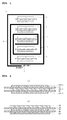
- FIG. 4 illustrates a fabricating process conducted in a practical fabricating apparatus for showing the fabricating process of the unit structure conceptually illustrated as the block diagram ( FIG. 3 ).
- a first laminator L1 and a second laminator L2 may be disposed on one fabricating line along the proceeding direction of a C-type bicell so as to continuously accomplish the first process to the third process.
- the first cathode material, the separator, the anode material, the separator, and the second cathode material may be loaded one by one, stacked and then laminated.
- the loading means supplying base material (that is, the first cathode material, the separator, the anode material, the second cathode material), which is the material of each component, into the laminator.
- the base materials may be supplied to the first laminator L1 through a loading unit (loading roll) at the same time, and the supplied base materials may be stacked by an order of first cathode 140/separator 150/anode 160/separator 170/second cathode 180 by the first laminator L1 one by one (see 'X' in FIG. 4 ).
- the second process and the third process may be conducted in the second laminator L2 simultaneously. That is, the second process of laminating the first separator 110 on the second cathode 180 of the C-type bicell stacked by the order of first cathode 140/separator 150/anode 160/separator 170/second cathode 180, and the third process of laminating the second separator/anode one by one on the first cathode may be conducted simultaneously by the second laminator L2 to manufacture the unit structure.
- FIG. 4 an example embodiment of supplying all of first separator, and the second separator/anode as a roll shape into the second laminator L2 is illustrated.
- an example of supplying a sheet shape other than the roll shape may be postulated.
- the second process and the third process may be conducted in sequence.
- both of the second separator/anode may be supplied into the second laminator L2 as the roll shape other than the sheet shape
- the second process and the third process may be conducted in sequence.
- the second process and the third process may be conducted in sequence even when all of the first separator, and the second separator/anode are supplied into the second laminator L2 as roll shapes.
- the second process and the third process are not necessary to be conducted by means of the second laminator L2.
- the second laminator L2 may be exclusively used for the second process and a separate laminator may be exclusively used for the third process in an example embodiment.
- the surface of the separators 110, 130, 150 and 170 may be coated by using a coating material having adhesiveness.
- the coating material may be a mixture of inorganic particles and a binder polymer.
- the inorganic particles may improve the thermal stability of the separators 110, 130, 150 and 170. That is, the inorganic particles may prevent the contraction of the separators 110, 130, 150 and 170 at a high temperature.
- the binder polymer may fix the inorganic particles.
- the inorganic particles may have a certain porous structure. Due to the porous structure, ions may smoothly move from the anode to the cathode, even though the inorganic particles may be coated on the separators 110, 130, 150 and 170.
- the mechanical stability of the separators 110, 130, 150 and 170 may be improved because the binder polymer may stably keeping the inorganic particles onto the separators 110, 130, 150 and 170. Further, the binder polymer may attach the separator onto the electrode more stably.
- the coating of the separator accomplished by the above-described method is called a safety reinforced separator (SRS) coating.
- the electrodes 120 and 140 are positioned on both sides of the second separator 130, however, one electrode 180 is positioned only on one side of the first separator 110.
- a coating material having adhesiveness may be coated onto both sides of the second separator 130, and the coating material may be coated only on one side of the first separator 110 facing the electrode. Accordingly, the fabricating cost of the unit structure may be decreased.
- the electrodes are exposed at both sides of the bicell for the bicell illustrated in FIG. 2 , two vision inspecting apparatuses are necessary. However, for the unit structure in accordance with exemplary embodiments, the electrode is not disposed on one side among the two sides of the first separator 110. Thus, the vision inspecting apparatus may be installed only near the electrode disposed at the opposite portion of the first separator of the unit structure. Therefore, the cost of the apparatus may be decreased.
- the application of a direct pressure onto the separators 110, 130, 150 and 170 by using a certain object may not be desirable.
- the separators 110, 130, 150 and 170 may be commonly extended outwardly from the electrode.
- an attempt may be made to weld the edge portions of the separators 110, 130, 150 and 170 to each other through, for example, sonication welding.
- the direct pressurization of a target object by using an apparatus named a horn is necessary.
- the horn When the edge portion of the separators 110, 130, 150 and 170 is directly pressurized by using the apparatus named horn, the horn may attach to the separator due to the coating material having the adhesiveness. In this case, the apparatus may be out of order. Thus, when the coating material having the adhesiveness is coated on the separators 110, 130, 150 and 170, a process of directly applying the pressure onto the separators 110, 130, 150 and 170 by using a certain object may not be desirable.
- the temperature applied for the laminating in the second process and the third process may be lower by about 20°C to 50°C than the temperature applied for the laminating in the first process.
- the pressure applied for the laminating in the second process and the third process may be about 40% to 60% of the pressure applied for the laminating in the first process.
- the temperature applied to an upper block and a lower block may be different for the remaining laminators other than the first laminator L1 for conducting the first process.
- unnecessary power consumption may be decreased by keeping the temperature of the lower block of the second laminator L2 contacting the second separator/anode higher by about 10°C to 30°C than the upper block of the second laminator L2 contacting the first separator.
- the unit structure having the same structure may be fabricated by using only one bicell among the A-type bicell and the C-type bicell in accordance with exemplary embodiments.
- An electrode assembly may be obtained from at least one of the unit structure or by stacking a plurality of the unit structures.
- the first process may be conducted by using only one line equipment among the line equipment for fabricating the A-type bicell and the line equipment for fabricating the C-type bicell.
- FIG. 5 is an exploded perspective view of a unit structure in accordance with an example embodiment
- FIG. 6 is a cross-sectional view of a unit structure in accordance with an example embodiment.
- the unit structure may be fabricated by using the C-type bicell or the A-type bicell as described above. For example, when the unit structure is fabricated by using the C-type bicell, the unit structure having the structure illustrated in FIG.
- 6 may be fabricated by conducting a first process of forming a C-type bicell having a first cathode 140/separator 150/anode 160/separator 170/second cathode 180 structure, conducting a second process of laminating the first separator 110 on the second cathode 180 of the C-type bicell, and conducting a third process of laminating the second separator 130/anode 120 on the first cathode one by one.
- the fabricating process of a medium and large size lithium ion polymer battery may be simplified and unified.
- investment on equipment may be decreased, and productivity may be increased.
- the secondary battery may be obtained only by applying the stacking process other than the commonly applied folding process, and so, the manufacturing process may be simplified, and the production cost may be extremely decreased.
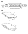
- FIG. 7 illustrates fixing members for fixing an electrode assembly in accordance with exemplary embodiments.
- the electrode assembly in accordance with exemplary embodiments may further include a fixing member T1 for fixing the side or the perimeter of the unit structure itself, or for fixing the side or the perimeter of the electrode assembly 100 formed by stacking a plurality of the unit structures.
- the fixing may be conducted by using a separate element at the side of the stacked structure.
- This fixing part may be applied by taping the perimeter of the stacked electrode assembly as illustrated in FIG. 7(a) , or by applying a fixing member T2 for fixing only the side of the electrode assembly as illustrated in FIG. 7(b) .
- the material of the fixing part may be selected from a different material of the separator.
- the fixing of the electrode assembly may be accomplished by welding the distal portion of the separator extruded to the side portion of the unit structure of the stacked electrode assembly other than using a separate fixing part.
- the separator may be formed by using at least one selected from the group consisting of a polyethylene film, a polypropylene film, a multi-layered film obtained by combining the films, a polymer film for a polymer electrolyte of polyvinylidene fluoride, polyethylene oxide, polyacrylonitrile, or a copolymer of polyvinylidene fluoride hexafluoropropylene with fine pore.
- An electrode provided in a radical cell is classified into an anode and a cathode and radical cell is manufactured by combining the anode and the cathode along with a separator interposed therebetween.
- the anode may be manufactured, for example, by coating slurry of a mixture of an anode active material, a conductive material and a binder on an anode current collector, drying and pressing. A filler may be added into the mixture as occasion demands. When the anode is accomplished as a sheet shape to be installed on a roll, the manufacturing rate of the radical cell may be increased.
- An anode current collector is generally manufactured to a thickness of about 3 to 500 ⁇ m.
- a material not inducing the chemical change of a battery and having a high conductivity may be used without limitation.
- stainless steel, aluminum, nickel, titanium, clacined carbon, a surface treated material of aluminum or stainless steel with carbon, nickel, titanium, silver, or the like may be used.
- the adhesiveness of an anode active material may be increased by forming minute embossing on the surface of the anode current collector.
- the anode current collector may have various shapes such as a film, a sheet, a foil, a net, a porous material, a foamed material, a non-woven material, and the like.
- An anode active material for a lithium secondary battery may include, for example, a layered compound of lithium cobalt oxide (LiCoO 2 ), lithium nickel oxide (LiNiO 2 ), etc. or a substituted compound with one or more transition metals; lithium manganese oxide such as Li 1+x Mn 2-x O 4 (in which x is 0 to 0.33), LiMnO 3 , LiMn 2 O 3 , LiMnO 2 , etc.; lithium copper oxide (Li 2 CuO 2 ) ; vanadium oxide such as LiV 3 O 8 , LiFe 3 O 4 , V 2 O 5 , Cu 2 V 2 O 7 , etc.
- a conductive material is added into a mixture including the anode active material by 1 to 50 wt% based on the total amount of the mixture.
- Any conductive material having conductivity without inducing the chemical change of a battery may be used without limitation.
- graphite such as natural graphite, synthetic graphite, etc.
- carbon black such as carbon black, acetylene black, ketjen black, channel black, furnace black, lamp black, thermal black, etc.
- conductive fiber such as carbon fiber, metal fiber, etc.
- a metal powder such as a carbon fluoride powder, an aluminum powder, a nickel powder, etc.
- conductive whisker such as potassium titanate, etc.
- conductive metal oxide such as titanium oxide, etc.
- a conductive material such as polyphenylene derivatives, etc.
- a binder is a component assisting the bonding of the active material with the conductive material and the bonding with the current collector, and is commonly included by about 1 to 50 wt% based on the total amount of the mixture including the anode active material.
- the binder may include polyfluoro vinylidene, polyvinyl alcohol, carboxymethyl cellulose (CMC), starch, hydroxypropyl cellulose, regenerated cellulose, polyvinyl pyrrolidone, tetrafluoroethylene, polyethylene, polypropylene, ethylene-propylene-diene polymer (EPDM), sulfonated EPDM, styrene butadiene rubber, fluorine rubber, various copolymers, etc.
- a filler is a component restraining the expansion of the anode and is selectively used.
- a material not inducing the chemical change of a battery and having a fiber phase may be used without limitation.
- olefin-based polymer such as polyethylene, polypropylene, and the like
- fiber phase material such as glass fiber, carbon fiber, and the like may be used.
- a cathode may be manufactured by coating a cathode active material on a cathode current collector, drying and pressing.
- a conductive material, a binder, a filler, etc. may be selectively included as occasion demands.
- the cathode is formed as a sheet shape possibly installed on a roll, the manufacturing rate of a radical cell may be increased.
- a cathode current collector is generally manufactured to a thickness of about 3 to 500 ⁇ m.
- a material not inducing the chemical change of a battery and having conductivity may be used without limitation.
- copper, stainless steel, aluminum, nickel, titanium, clacined carbon, a surface treated material of copper or stainless steel with carbon, nickel, titanium, silver, an aluminum-cadmium alloy, etc. may be used.
- the adhesiveness of the cathode active material may be increased by forming minute embossing on the surface of the cathode current collector.
- the cathode current collector may have various shapes such as a film, a sheet, a foil, a net, a porous material, a foamed material, a non-woven material, etc.
- a cathode active material may include, for example, carbon such as non-graphitizable carbon, graphite-based carbon, etc.; a metal complex oxide such as Li x Fe 2 O 3 (0 ⁇ x ⁇ 1), Li x WO 2 (0 ⁇ x ⁇ 1), Sn x Me 1-x Me' y O z (Me: Mn, Fe, Pb, Ge; Me': Al, B, P, Si, elements found in Group 1, Group 2 and Group 3 in a periodic table, halogen; 0 ⁇ x ⁇ 1; 1 ⁇ y ⁇ 3; 1 ⁇ z ⁇ 8), etc.; a lithium metal; a lithium alloy; a silicon-based alloy; a tin-based alloy; a metal oxide such as SnO, SnO 2 , PbO, PbO 2 , Pb 2 O 3 , Pb 3 O 4 , Sb 2 O 3 , Sb 2 O 4 , Sb 2 O 5 , GeO, GeO 2 , Bi 2 O 3 , Bi 2 O 4
- a separator forms a radical cell through conducting a simple stacking process apart from a folding process or a roll process to accomplish the simple stacking.
- the attachment of the separator and the electrode may be accomplished by pressure (or by pressure and heat) in a laminator. From the above-described process, a stable interface contact between the electrode and the separator sheet may become possible.
- any material may be used for the manufacture of the separator, that may exhibit insulating properties and have a porous structure for the movement of ions.
- an insulating thin film having a high ion transmittance and mechanical strength may be used.
- the pore diameter of the separator or the separator sheet is commonly about 0.01 to 10 ⁇ m, and the thickness thereof is commonly about 5 to 300 ⁇ m.
- an olefin-based polymer such as chemical-resistant and hydrophobic polypropylene, etc.; a sheet or a non-woven fabric obtained by using glass fiber, polyethylene, or the like
- the solid electrolyte may also function as the separator.
- a polyethylene film, a polypropylene film, or a multi-layered film obtained by combining the films, or a polymer film for a polymer electrolyte or a gel-type polymer electrolyte such as polyvinylidene fluoride, polyethylene oxide, polyacrylonitrile, or polyvinylidene fluoride hexafluoropropylene copolymer, may be used.
- the electrode assembly 100 according to the present invention may be applied in an electrochemical cell producing electricity through the electrochemical reaction of an anode and a cathode.
- the electrochemical cell include a super capacitor, an ultra capacitor, a secondary battery, a fuel cell, all sorts of sensors, an apparatus for electrolysis, an electrochemical reactor, and the like.
- the secondary battery is particularly preferred.
- the secondary battery has a structure in which a chargeable/dischargeable electrode assembly having an impregnated state with an ion-containing electrolyte is built in a battery case.
- the secondary battery may be a lithium secondary battery.
- a lithium secondary battery attracts much concern as for a power source of a large size device as well as a small size mobile device.
- a light weight lithium secondary battery may be preferred for applying thereof in these fields.
- a built-in structure including an electrode assembly in a pouch-type case of an aluminum laminate sheet may be used. Since the features on the lithium secondary battery are well known in this art, the explanation on the lithium secondary battery will be omitted.
- the lithium secondary battery when used as the power source of a medium and large size device, a secondary battery maximally restraining the deterioration of an operating performance for a long time, having good lifetime properties and having a structure possibly being mass-produced with a lower cost, may be preferred.
- the secondary battery including the electrode assembly of the present invention may be preferably used as a unit battery in a medium and large size battery module.
- a battery pack including a battery module including a plurality of secondary batteries may be used as a power source in at least one medium and large size device selected from the group consisting of a power tool; an electric vehicle selected from the group consisting of an electric vehicle (EV), a hybrid electric vehicle (HEV), and a plug-in hybrid electric vehicle (PHEV); an E-bike; an E-scooter; an electric golf cart; an electric truck; and an electric commercial vehicle.
- a power tool selected from the group consisting of a power tool
- an electric vehicle selected from the group consisting of an electric vehicle (EV), a hybrid electric vehicle (HEV), and a plug-in hybrid electric vehicle (PHEV)
- E-bike an E-scooter
- an electric golf cart an electric truck
- an electric commercial vehicle an electric commercial vehicle
- the medium and large size battery module is constituted of a plurality of unit batteries connected in a serial system or a serial/parallel system so as to provide a high output and high capacity.
- the techniques on these features are well known in this art. Thus, the explanation on the features will be omitted in this application.
Landscapes
- Chemical & Material Sciences (AREA)
- Chemical Kinetics & Catalysis (AREA)
- Electrochemistry (AREA)
- General Chemical & Material Sciences (AREA)
- Engineering & Computer Science (AREA)
- Manufacturing & Machinery (AREA)
- Secondary Cells (AREA)
- Cell Separators (AREA)
- Battery Electrode And Active Subsutance (AREA)
- Electric Double-Layer Capacitors Or The Like (AREA)
Abstract
Description
- This application claims the priorities of Korean Patent Application Nos.
10-2012-0069831 filed on June 28, 2012 10-2013-0074675 filed on June 27, 2013 - The present invention relates to a fabricating method of a unit structure materializing an electrode assembly fabricated by a stacking method other than a folding method, a fabricating method of the electrode assembly and an electrochemical cell including the electrode assembly.
- A secondary battery attracts attention as a power source of an electric vehicle (EV), a hybrid electric vehicle (HEV), a parallel hybrid electric vehicle (PHEV), and the like, which have been suggested as alternatives for solving defects such as environmental contamination due to commonly used gasoline vehicles, diesel vehicles, and the like using fossil fuels. In a medium and large size device such as automobiles, a medium and large size battery module in which a plurality of battery cells is electrically connected is used due to the need of high power and high capacity.
- However, since the medium and large size battery module is necessary to be manufactured so as to have a small size and a light weight, a square shape battery, a pouch shape battery, and the like, which may be stacked in a high degree and have a light weight when compared with the capacity, are widely used as the battery cells of the medium and large size battery module.
- In the case of the battery cell, an electrode assembly is included. Generally, the electrode assembly is classified according to the structure of the electrode assembly including an anode/separator/cathode structure.
- Typically, the electrode assembly may be classified into a jelly-roll (a wrapping type) electrode assembly, in which anodes and cathodes having long sheet shapes along with an interposed separator are wrapped, a stack type (a laminated type) electrode assembly, in which a plurality of anodes and cathodes along with interposed separators, which are cut into specific size units, are stacked one by one, and a stack/folding type electrode assembly.
- First, the stack/folding type electrode assembly disclosed in Korean Patent Application Publication Nos.
2001-0082059 2001-0082060 - Referring to
FIG. 1 , an electrode assembly 1 of a stack/folding structure includes a plurality of overlappedfull cells separator sheet 5 is interposed. Theseparator sheet 5 has a unit length possibly wrapping the full cells. Theseparator sheet 5 initiated from the centralfull cell 1b is bent inward by the unit length while continuously wrapping each of the full cells to the outermost full cell 4 so as to be interposed in the overlapped parts of the full cells. The distal portion of theseparator sheet 5 is finished by conducting heat welding or attaching using an adhesion tape 6. The stack/folding type electrode assembly is manufactured by, for example, arranging thefull cells separator sheet 5 having a long length and wrapping from one distal portion of theseparator sheet 5 in sequence. However, in this structure, a temperature gradient may be generated between theelectrode assemblies electrode assemblies 3 and 4 disposed at the outer portion to produce different heat emitting efficiency. Thus, the lifetime of the electrode assembly may be decreased when used for a long time. - The manufacturing process of the electrode assembly is conducted by using two lamination apparatuses for manufacturing each electrode assembly and one additional folding apparatus as a separate apparatus. Therefore, the decrease of the tack time of the manufacturing process has a limitation. Particularly, the minute aligning of the electrode assemblies disposed up and down is difficult in the structure accomplishing the stacked structure through the folding. Thus, the manufacture of an assembly having a reliable quality is very difficult.
-
FIG. 2 illustrates A type and C type bicell structures which are unit structures applicable instead of the full cell in the electrode assembly of the above-described stack/folding type structure inFIG. 1 . At the center portion of the electrode assembly of the stack/folding structure, which is the initiating point of wrapping, a bicell ('A-type bicell') having (a) an anode/separator/cathode/separator/anode structure or a bicell ('C-type bicell') having (b) a cathode/separator/anode/separator/cathode structure, wrapped with a separator sheet may be disposed. - That is, the common bicell may have a structure of the 'A-type bicell' having a stacked structure of a
double side anode 10, aseparator 20, adouble side cathode 30, aseparator 40 and a double side anode 50 one by one as illustrated inFIG. 2(a) , or the 'C-type bicell' having a stacked structure of adouble side cathode 30, aseparator 20, adouble side anode 10, aseparator 40 and adouble side cathode 60 one by one as illustrated inFIG. 2(b) . - In the electrode assembly structure fabricated by applying the folding process, a folding apparatus may be separately necessary. When applying the bicell structure, the bicells may be fabricated by two types (that is, A-type and C-type) and stacked. Before conducting the folding, the keeping of accurate distance between the bicells disposed on a long separator sheet may be very difficult. That is, when conducting the folding, the accurate alignment of upper and lower unit cells (meaning the full cells or the bicells) may be difficult. In addition, when manufacturing a high capacity cell, considerable time may be necessary for changing the types.
-
- (Patent Document 1) Korean Publication Patent No.
2001-0045056 - (Patent Document 2) Korean Publication Patent No.
2011-0082745 - An aspect of the present invention considering the above-described defects provides a fabricating method of an electrode assembly and a structure of an electrode assembly by which the fabricating method of a medium and large size lithium ion polymer battery may be simplified and unified through fabricating one kind of unit structure, deviated from the common fabricating method of an electrode assembly in which two types (A-type and C-type) of bicells are necessary to be fabricated, investment on facility may be decreased, and productivity may be increased,
- Another aspect of the present invention provides a fabricating method of a unit structure having a novel structure by using a lamination apparatus for fabricating a common A-type bicell and a lamination apparatus for fabricating a C-type bicell, and utilizing common A-type bicell and C-type bicell as they are without abrogation.
- According to an aspect of the present invention, there is provided a fabricating method of an electrode assembly in which a unit structure of the electrode assembly is manufactured by conducting a first process of laminating and forming a bicell having a first electrode/separator/second electrode/separator/first electrode structure, conducting a second process of laminating a first separator on one of the first electrode among two of the first electrodes, and conducting a third process of laminating second separator/second electrode one by one on the other first electrode among the two of the first electrodes.
- According to another aspect of the present invention, there is provided an electrode assembly fabricated by using the unit structure formed through the above-described processes, and a secondary battery and a medium and large size battery module is manufactured by using the electrode assembly.
- According to the present invention, a fabricating method by which a medium and large size lithium ion polymer battery may be simplified and unified through fabricating one kind of unit structure, an apparatus investment on facility may be decreased, and productivity may be increased, and the structure of an electrode assembly may be provided.
- In addition, the lamination apparatus for fabricating a common A-type bicell and the lamination apparatus for fabricating a common C-type bicell may be used as they are, and the common A-type bicell or the C-type bicell may be used as they are without abrogation for fabricating a unit cell having a new structure.
- The above and other aspects, features and other advantages of the present invention will be more clearly understood from the following detailed description taken in conjunction with the accompanying drawings, in which:
-
FIG. 1 is a conceptual diagram illustrating a folding structure of a common stack/folding type electrode assembly; -
FIG. 2 illustrates cross-sectional views of an A-type bicell and a C-type bicell applied instead of a full cell in the stack/folding type electrode assembly inFIG. 1 ; -
FIG. 3 is a block diagram illustrating a fabricating process of a unit structure included in an electrode assembly in accordance with an example embodiment; -
FIG. 4 is a schematic diagram for illustrating a fabricating process of a unit structure by using a fabricating apparatus for manufacturing the unit structure inFIG. 3 ; -
FIG. 5 is an exploded perspective view of a unit structure in accordance with an example embodiment; -
FIG. 6 is a cross-sectional view of a unit structure in accordance with an example embodiment; and -
FIG. 7 illustrates electrode assemblies including fixing members for fixing electrode assemblies in accordance with example embodiments. - Exemplary embodiments of the present invention will now be described in detail with reference to the accompanying drawings. In explaining the accompanying drawings, the same reference symbols may be designated to the same elements, and duplicating explanation thereon may be omitted. Although the terms first, second, etc. may be used herein to describe various elements, these elements, should not be limited by these terms. These terms are only used to distinguish one element from another element.
- The core technology of the fabricating process of an electrode assembly in accordance with the present inventive concept is the forming of a unit structure. Particularly, the unit structure may be formed by conducting a first process of laminating and forming a bicell having a first electrode/separator/second electrode/separator/first electrode structure, by conducting a second process of laminating a first separator on one of the first electrode among the two of the first electrodes included in the bicell formed by the first process, and by conducting a third process of laminating second separator/second electrode one by one on the other first electrode among the two of the first electrodes included in the bicell formed by the first process.
- Here, the first electrode/second electrode may be cathode/anode or anode/cathode. However, for the convenience of explanation, for example, the first electrode is considered as a cathode, and the second electrode is considered as an anode herein below.
- Referring to
FIG. 3 , the unit structure of the above described structure may be fabricated by stacking a first cathode material, a separator, an anode material, a separator and a second cathode material one by one, loading the stacked structure on a laminator, and laminating to fabricate a bicell (C-type bicell) having a first cathode/separator/anode/separator/second cathode structure (the first process). - Then, the second process of laminating the first separator on the second cathode of the C-type bicell may be conducted, and the third process of laminating a second separator and an anode on the first cathode one by one may be conducted.
- Since an example embodiment of conducting the second process and the third process simultaneously is illustrated in
FIG. 3 , the step of disposing the first separator on the second cathode in the second process, and the step of disposing the second separator and the anode on the first cathode in the third process may be conducted first. After conducting the steps, the laminating may be conducted to complete the second process and the third process together. -
FIG. 4 illustrates a fabricating process conducted in a practical fabricating apparatus for showing the fabricating process of the unit structure conceptually illustrated as the block diagram (FIG. 3 ). - As illustrated in
FIG. 4 , a first laminator L1 and a second laminator L2 may be disposed on one fabricating line along the proceeding direction of a C-type bicell so as to continuously accomplish the first process to the third process. In the first laminator L1, the first cathode material, the separator, the anode material, the separator, and the second cathode material may be loaded one by one, stacked and then laminated. Here, the loading means supplying base material (that is, the first cathode material, the separator, the anode material, the second cathode material), which is the material of each component, into the laminator. The base materials may be supplied to the first laminator L1 through a loading unit (loading roll) at the same time, and the supplied base materials may be stacked by an order offirst cathode 140/separator 150/anode 160/separator 170/second cathode 180 by the first laminator L1 one by one (see 'X' inFIG. 4 ). - Then, the second process and the third process may be conducted in the second laminator L2 simultaneously. That is, the second process of laminating the
first separator 110 on thesecond cathode 180 of the C-type bicell stacked by the order offirst cathode 140/separator 150/anode 160/separator 170/second cathode 180, and the third process of laminating the second separator/anode one by one on the first cathode may be conducted simultaneously by the second laminator L2 to manufacture the unit structure. - In
FIG. 4 , an example embodiment of supplying all of first separator, and the second separator/anode as a roll shape into the second laminator L2 is illustrated. However, an example of supplying a sheet shape other than the roll shape may be postulated. In this case, the second process and the third process may be conducted in sequence. - In addition, even though both of the second separator/anode may be supplied into the second laminator L2 as the roll shape other than the sheet shape, the second process and the third process may be conducted in sequence. For example, with reference to
FIG. 4 , when the laminating is conducted with thefirst separator 110 supplied on thesecond cathode 180 while stopping the loading of thesecond separator 130 and theanode 120 to be supplied on thefirst cathode 140, the second process may be conducted. When the laminating is conducted with thesecond separator 130 and theanode 120 supplied on thefirst cathode 140 while stopping the loading of thefirst separator 110 to be supplied on thesecond cathode 180, the third process may be conducted. As described above, the second process and the third process may be conducted in sequence even when all of the first separator, and the second separator/anode are supplied into the second laminator L2 as roll shapes. - Here, the second process and the third process are not necessary to be conducted by means of the second laminator L2. Of course, the second laminator L2 may be exclusively used for the second process and a separate laminator may be exclusively used for the third process in an example embodiment.
- Meanwhile, the surface of the
separators separators separators separators separators separators - When referring to the fabricated state of the unit structure, the
electrodes second separator 130, however, oneelectrode 180 is positioned only on one side of thefirst separator 110. Thus, a coating material having adhesiveness may be coated onto both sides of thesecond separator 130, and the coating material may be coated only on one side of thefirst separator 110 facing the electrode. Accordingly, the fabricating cost of the unit structure may be decreased. In addition, since the electrodes are exposed at both sides of the bicell for the bicell illustrated inFIG. 2 , two vision inspecting apparatuses are necessary. However, for the unit structure in accordance with exemplary embodiments, the electrode is not disposed on one side among the two sides of thefirst separator 110. Thus, the vision inspecting apparatus may be installed only near the electrode disposed at the opposite portion of the first separator of the unit structure. Therefore, the cost of the apparatus may be decreased. - For reference, when a coating material having adhesiveness is coated on the
separators separators separators separators separators separators separators - The temperature applied for the laminating in the second process and the third process may be lower by about 20°C to 50°C than the temperature applied for the laminating in the first process. The pressure applied for the laminating in the second process and the third process may be about 40% to 60% of the pressure applied for the laminating in the first process. As described above, by differentiating the temperature and the pressure at the second process and the third process from the first process, the processing conditions may be simplified, and the cost necessary for conducting the processes may be decreased.
- In addition, the temperature applied to an upper block and a lower block may be different for the remaining laminators other than the first laminator L1 for conducting the first process.
- For example, unnecessary power consumption may be decreased by keeping the temperature of the lower block of the second laminator L2 contacting the second separator/anode higher by about 10°C to 30°C than the upper block of the second laminator L2 contacting the first separator.
- When an electrode assembly is fabricated by using a common bicell, a line equipment for fabricating an A-type bicell and a line equipment for fabricating a C-type bicell are necessary to be installed respectively, and two kinds of the bicells are necessary to be stacked. On the contrary, the unit structure having the same structure may be fabricated by using only one bicell among the A-type bicell and the C-type bicell in accordance with exemplary embodiments. An electrode assembly may be obtained from at least one of the unit structure or by stacking a plurality of the unit structures. Thus, the first process may be conducted by using only one line equipment among the line equipment for fabricating the A-type bicell and the line equipment for fabricating the C-type bicell. By attaching an equipment for conducting the second process and the third process onto the line equipment, the unit structure may be manufactured thorough continuous process.
-
FIG. 5 is an exploded perspective view of a unit structure in accordance with an example embodiment, andFIG. 6 is a cross-sectional view of a unit structure in accordance with an example embodiment. The unit structure may be fabricated by using the C-type bicell or the A-type bicell as described above. For example, when the unit structure is fabricated by using the C-type bicell, the unit structure having the structure illustrated inFIG. 6 may be fabricated by conducting a first process of forming a C-type bicell having afirst cathode 140/separator 150/anode 160/separator 170/second cathode 180 structure, conducting a second process of laminating thefirst separator 110 on thesecond cathode 180 of the C-type bicell, and conducting a third process of laminating thesecond separator 130/anode 120 on the first cathode one by one. - Through fabricating the electrode assembly by using the unit structure having the above-described structure, the fabricating process of a medium and large size lithium ion polymer battery may be simplified and unified. In addition, investment on equipment may be decreased, and productivity may be increased. Further, the secondary battery may be obtained only by applying the stacking process other than the commonly applied folding process, and so, the manufacturing process may be simplified, and the production cost may be extremely decreased.
-
FIG. 7 illustrates fixing members for fixing an electrode assembly in accordance with exemplary embodiments. - That is, the electrode assembly in accordance with exemplary embodiments may further include a fixing member T1 for fixing the side or the perimeter of the unit structure itself, or for fixing the side or the perimeter of the
electrode assembly 100 formed by stacking a plurality of the unit structures. - In order to confirm the stability of the stacking of the simply stacked structure, the fixing may be conducted by using a separate element at the side of the stacked structure. This fixing part may be applied by taping the perimeter of the stacked electrode assembly as illustrated in
FIG. 7(a) , or by applying a fixing member T2 for fixing only the side of the electrode assembly as illustrated inFIG. 7(b) . In addition, the material of the fixing part may be selected from a different material of the separator. - Of course, the fixing of the electrode assembly may be accomplished by welding the distal portion of the separator extruded to the side portion of the unit structure of the stacked electrode assembly other than using a separate fixing part. The separator may be formed by using at least one selected from the group consisting of a polyethylene film, a polypropylene film, a multi-layered film obtained by combining the films, a polymer film for a polymer electrolyte of polyvinylidene fluoride, polyethylene oxide, polyacrylonitrile, or a copolymer of polyvinylidene fluoride hexafluoropropylene with fine pore.
- Hereinafter, particular materials and constitutional features of constituent elements of the electrode assembly according to the present invention will be explained.
- An electrode provided in a radical cell is classified into an anode and a cathode and radical cell is manufactured by combining the anode and the cathode along with a separator interposed therebetween. The anode may be manufactured, for example, by coating slurry of a mixture of an anode active material, a conductive material and a binder on an anode current collector, drying and pressing. A filler may be added into the mixture as occasion demands. When the anode is accomplished as a sheet shape to be installed on a roll, the manufacturing rate of the radical cell may be increased.
- An anode current collector is generally manufactured to a thickness of about 3 to 500 µm. For the anode current collector, a material not inducing the chemical change of a battery and having a high conductivity may be used without limitation. For example, stainless steel, aluminum, nickel, titanium, clacined carbon, a surface treated material of aluminum or stainless steel with carbon, nickel, titanium, silver, or the like may be used. The adhesiveness of an anode active material may be increased by forming minute embossing on the surface of the anode current collector. The anode current collector may have various shapes such as a film, a sheet, a foil, a net, a porous material, a foamed material, a non-woven material, and the like.
- An anode active material for a lithium secondary battery may include, for example, a layered compound of lithium cobalt oxide (LiCoO2), lithium nickel oxide (LiNiO2), etc. or a substituted compound with one or more transition metals; lithium manganese oxide such as Li1+xMn2-xO4 (in which x is 0 to 0.33), LiMnO3, LiMn2O3, LiMnO2, etc.; lithium copper oxide (Li2CuO2) ; vanadium oxide such as LiV3O8, LiFe3O4, V2O5, Cu2V2O7, etc. ; Ni site-type lithium nickel oxide represented by Chemical Formula of LiNi1-xMxO2 (in which, M=Co, Mn, Al, Cu, Fe, Mg, B or Ga, x=0.01 to 0.3); lithium manganese complex oxide represented by Chemical Formulae LiMn2-xMxO2 (in which M=Co, Ni, Fe, Cr, Zn or Ta, and x=0.01 to 0.1) or Li2Mn3MO8 (in which, M=Fe, Co, Ni, Cu or Zn) ; LiMn2O4 in which a portion of Li is substituted with alkaline earth ions; a disulfide compound; Fe2(MoO4)3, and the like, without limitation.
- Generally, a conductive material is added into a mixture including the anode active material by 1 to 50 wt% based on the total amount of the mixture. Any conductive material having conductivity without inducing the chemical change of a battery may be used without limitation. For example, graphite such as natural graphite, synthetic graphite, etc.; carbon black such as carbon black, acetylene black, ketjen black, channel black, furnace black, lamp black, thermal black, etc.; conductive fiber such as carbon fiber, metal fiber, etc.; a metal powder such as a carbon fluoride powder, an aluminum powder, a nickel powder, etc.; conductive whisker such as potassium titanate, etc.; conductive metal oxide such as titanium oxide, etc.; a conductive material such as polyphenylene derivatives, etc. may be used
- A binder is a component assisting the bonding of the active material with the conductive material and the bonding with the current collector, and is commonly included by about 1 to 50 wt% based on the total amount of the mixture including the anode active material. Examples of the binder may include polyfluoro vinylidene, polyvinyl alcohol, carboxymethyl cellulose (CMC), starch, hydroxypropyl cellulose, regenerated cellulose, polyvinyl pyrrolidone, tetrafluoroethylene, polyethylene, polypropylene, ethylene-propylene-diene polymer (EPDM), sulfonated EPDM, styrene butadiene rubber, fluorine rubber, various copolymers, etc.
- A filler is a component restraining the expansion of the anode and is selectively used. A material not inducing the chemical change of a battery and having a fiber phase may be used without limitation. For example, olefin-based polymer such as polyethylene, polypropylene, and the like; fiber phase material such as glass fiber, carbon fiber, and the like may be used.
- A cathode may be manufactured by coating a cathode active material on a cathode current collector, drying and pressing. A conductive material, a binder, a filler, etc. may be selectively included as occasion demands. When the cathode is formed as a sheet shape possibly installed on a roll, the manufacturing rate of a radical cell may be increased.
- A cathode current collector is generally manufactured to a thickness of about 3 to 500 µm. For the cathode current collector, a material not inducing the chemical change of a battery and having conductivity may be used without limitation. For example, copper, stainless steel, aluminum, nickel, titanium, clacined carbon, a surface treated material of copper or stainless steel with carbon, nickel, titanium, silver, an aluminum-cadmium alloy, etc. may be used. Also, as for the anode current collector, the adhesiveness of the cathode active material may be increased by forming minute embossing on the surface of the cathode current collector. The cathode current collector may have various shapes such as a film, a sheet, a foil, a net, a porous material, a foamed material, a non-woven material, etc.
- A cathode active material may include, for example, carbon such as non-graphitizable carbon, graphite-based carbon, etc.; a metal complex oxide such as LixFe2O3 (0≤x≤1), LixWO2 (0≤x≤1), SnxMe1-xMe'yOz (Me: Mn, Fe, Pb, Ge; Me': Al, B, P, Si, elements found in Group 1,
Group 2 andGroup 3 in a periodic table, halogen; 0<x≤1; 1≤y≤3; 1≤z≤8), etc.; a lithium metal; a lithium alloy; a silicon-based alloy; a tin-based alloy; a metal oxide such as SnO, SnO2, PbO, PbO2, Pb2O3, Pb3O4, Sb2O3, Sb2O4, Sb2O5, GeO, GeO2, Bi2O3, Bi2O4, Bi2O5, etc.; a conductive polymer such as polyacetylene, etc.; Li-Co-Ni-based material, etc. - A separator forms a radical cell through conducting a simple stacking process apart from a folding process or a roll process to accomplish the simple stacking. Particularly, the attachment of the separator and the electrode may be accomplished by pressure (or by pressure and heat) in a laminator. From the above-described process, a stable interface contact between the electrode and the separator sheet may become possible.
- Any material may be used for the manufacture of the separator, that may exhibit insulating properties and have a porous structure for the movement of ions. For example, an insulating thin film having a high ion transmittance and mechanical strength may be used. The pore diameter of the separator or the separator sheet is commonly about 0.01 to 10 µm, and the thickness thereof is commonly about 5 to 300 µm.
- As for the separator, for example, an olefin-based polymer such as chemical-resistant and hydrophobic polypropylene, etc.; a sheet or a non-woven fabric obtained by using glass fiber, polyethylene, or the like, may be used. When a solid electrolyte such as a polymer is used as an electrolyte, the solid electrolyte may also function as the separator. Preferably, a polyethylene film, a polypropylene film, or a multi-layered film obtained by combining the films, or a polymer film for a polymer electrolyte or a gel-type polymer electrolyte such as polyvinylidene fluoride, polyethylene oxide, polyacrylonitrile, or polyvinylidene fluoride hexafluoropropylene copolymer, may be used.
- Hereinafter, an electrochemical device in which the
electrode assembly 100 according to the present invention may be applicable, will be explained. - The
electrode assembly 100 according to the present invention may be applied in an electrochemical cell producing electricity through the electrochemical reaction of an anode and a cathode. Typical examples of the electrochemical cell include a super capacitor, an ultra capacitor, a secondary battery, a fuel cell, all sorts of sensors, an apparatus for electrolysis, an electrochemical reactor, and the like. The secondary battery is particularly preferred. - The secondary battery has a structure in which a chargeable/dischargeable electrode assembly having an impregnated state with an ion-containing electrolyte is built in a battery case. In a preferred embodiment, the secondary battery may be a lithium secondary battery.
- Recently, a lithium secondary battery attracts much concern as for a power source of a large size device as well as a small size mobile device. A light weight lithium secondary battery may be preferred for applying thereof in these fields. As one method of decreasing the weight of the secondary battery, a built-in structure including an electrode assembly in a pouch-type case of an aluminum laminate sheet may be used. Since the features on the lithium secondary battery are well known in this art, the explanation on the lithium secondary battery will be omitted.
- In addition, as described above, when the lithium secondary battery is used as the power source of a medium and large size device, a secondary battery maximally restraining the deterioration of an operating performance for a long time, having good lifetime properties and having a structure possibly being mass-produced with a lower cost, may be preferred. From this point of view, the secondary battery including the electrode assembly of the present invention may be preferably used as a unit battery in a medium and large size battery module.
- A battery pack including a battery module including a plurality of secondary batteries may be used as a power source in at least one medium and large size device selected from the group consisting of a power tool; an electric vehicle selected from the group consisting of an electric vehicle (EV), a hybrid electric vehicle (HEV), and a plug-in hybrid electric vehicle (PHEV); an E-bike; an E-scooter; an electric golf cart; an electric truck; and an electric commercial vehicle.
- The medium and large size battery module is constituted of a plurality of unit batteries connected in a serial system or a serial/parallel system so as to provide a high output and high capacity. The techniques on these features are well known in this art. Thus, the explanation on the features will be omitted in this application.
- While the present invention has been shown and described in connection with the exemplary embodiments, it will be apparent to those skilled in the art that modifications and variations can be made without departing from the spirit and scope of the invention as defined by the appended claims.
-
- 110:
- First separator
- 120:
- Anode
- 130:
- Second separator
- 140:
- First cathode
- 150:
- Separator
- 160:
- Anode
- 170:
- Separator
- 180:
- Second cathode
Claims (17)
- A fabricating method of an electrode assembly comprising a first electrode, a second electrode and a separator, a unit structure of the electrode assembly being manufactured by:conducting a first process of laminating and forming a bicell having a first electrode/separator/second electrode/separator/first electrode structure;conducting a second process of laminating a first separator on one of the first electrode among two of the first electrodes; andconducting a third process of laminating second separator/second electrode one by one on the other first electrode among the two of the first electrodes.
- The fabricating method of an electrode assembly of claim 1, wherein a plurality of the unit structures are stacked.
- The fabricating method of an electrode assembly of claim 1, wherein the second process and the third process are conducted by using separate laminators.
- The fabricating method of an electrode assembly of claim 1, wherein the second process and the third process are conducted simultaneously or in sequence by using one laminator.
- The fabricating method of an electrode assembly of claim 1, wherein both sides of the second separator are coated with a coating material having adhesiveness, and one side of the first separator making a contact with the first electrode is coated with the coating material having adhesiveness.
- The fabricating method of an electrode assembly of claim 1, wherein both sides of the separators included in the bicell are coated with a coating material having adhesiveness.
- The fabricating method of an electrode assembly of claim 5 or 6, wherein the coating material is a mixture of inorganic particles and a binder polymer.
- The fabricating method of an electrode assembly of claim 1, wherein the first electrode and the second electrode are double sided electrodes comprising a coated structure on both sides of a current collector with an active material.
- The fabricating method of an electrode assembly of claim 1, wherein a temperature applied for the laminating in the second process or the third process is lower by 20°C to 50°C than a temperature applied for the laminating in the first process.
- The fabricating method of an electrode assembly of claim 1, wherein a pressure applied for the laminating in the second process or the third process is 40% to 60% of a pressure applied for the laminating in the first process.
- The fabricating method of an electrode assembly of claim 3 or 4, wherein a temperature applied to an upper block and a lower block of remaining laminators other than the laminator for conducting the first process is different by 10°C to 30°C.
- An electrode assembly comprising at least one unit structure manufactured by the fabricating method of the electrode assembly according to claim 1.
- The electrode assembly of claim 12, further comprising a fixing member for fixing a side or a perimeter of the unit structure.
- The electrode assembly of claim 12, further comprising a fixing member for fixing a side or a perimeter of the electrode assembly.
- The electrode assembly of claim 13 or 14, wherein the fixing member is formed by using a material different from a material of the separator.
- The electrode assembly of claim 12, wherein the first electrode and the second electrode are double sided electrodes comprising a coated structure on both sides of a current collector with an active material.
- An electrochemical cell comprising the electrode assembly according to claim 12.
Applications Claiming Priority (3)
| Application Number | Priority Date | Filing Date | Title |
|---|---|---|---|
| KR20120069831 | 2012-06-28 | ||
| KR1020130074675A KR101523427B1 (en) | 2012-06-28 | 2013-06-27 | Fabricating method of electrode assembly |
| PCT/KR2013/005765 WO2014003485A1 (en) | 2012-06-28 | 2013-06-28 | Electrode assembly, method for manufacturing electrode assembly, and electrochemical device comprising electrode assembly |
Publications (3)
| Publication Number | Publication Date |
|---|---|
| EP2757625A1 true EP2757625A1 (en) | 2014-07-23 |
| EP2757625A4 EP2757625A4 (en) | 2015-12-16 |
| EP2757625B1 EP2757625B1 (en) | 2016-11-16 |
Family
ID=50140532
Family Applications (1)
| Application Number | Title | Priority Date | Filing Date |
|---|---|---|---|
| EP13810294.2A Active EP2757625B1 (en) | 2012-06-28 | 2013-06-28 | Method for manufacturing electrode assembly and electrochemical device |
Country Status (7)
| Country | Link |
|---|---|
| US (1) | US9806316B2 (en) |
| EP (1) | EP2757625B1 (en) |
| JP (1) | JP5855267B2 (en) |
| KR (1) | KR101523427B1 (en) |
| CN (1) | CN103959542B (en) |
| TW (1) | TWI517476B (en) |
| WO (1) | WO2014003485A1 (en) |
Cited By (1)
| Publication number | Priority date | Publication date | Assignee | Title |
|---|---|---|---|---|
| EP2892102A4 (en) * | 2013-09-26 | 2016-08-24 | Lg Chemical Ltd | METHOD FOR MANUFACTURING AN ELECTRODE ASSEMBLY |
Families Citing this family (14)
| Publication number | Priority date | Publication date | Assignee | Title |
|---|---|---|---|---|
| DE19739834C1 (en) | 1997-09-11 | 1998-10-08 | Scs Gmbh | Stretch fabric finishing |
| KR101775230B1 (en) * | 2014-10-02 | 2017-09-05 | 주식회사 엘지화학 | Laminating apparatus and method for secondary battery |
| WO2016053060A1 (en) * | 2014-10-02 | 2016-04-07 | 주식회사 엘지화학 | Secondary battery laminating device and secondary battery laminating method |
| CN107305959B (en) * | 2016-04-25 | 2022-05-13 | 松下知识产权经营株式会社 | Battery, battery manufacturing method, and battery manufacturing apparatus |
| US10804571B2 (en) * | 2016-11-24 | 2020-10-13 | Lg Chem, Ltd. | Method of manufacturing battery cell comprising electrode having aperture |
| KR101964713B1 (en) * | 2016-12-15 | 2019-04-02 | 주식회사 엘지화학 | Battery Cell Formation Tray Comprising Fixing Member |
| KR102500240B1 (en) | 2018-06-29 | 2023-02-16 | 주식회사 엘지에너지솔루션 | Method of manufacturing electrode assembly |
| KR102732915B1 (en) | 2018-11-23 | 2024-11-22 | 주식회사 엘지에너지솔루션 | Lamination apparatus and method, producing facility of secondary battery including the same |
| KR102594367B1 (en) * | 2019-04-16 | 2023-10-27 | 주식회사 엘지에너지솔루션 | Electrode assembly comprising coated part with different color and method for preparing the same |
| CN112768811B (en) | 2019-11-01 | 2024-09-24 | 通用汽车环球科技运作有限责任公司 | Capacitor-assisted electrochemical device with hybrid architecture |
| KR102666729B1 (en) * | 2021-03-22 | 2024-05-16 | 주식회사 엘지에너지솔루션 | Electrode assembly and secondary battery including the same |
| HUE068090T2 (en) | 2021-09-17 | 2024-12-28 | Univ Berlin Tech | Method and device for creating an electrode-separator unit for a battery cell |
| KR20230139517A (en) * | 2022-03-28 | 2023-10-05 | 주식회사 엘지에너지솔루션 | Assembly manufacturing equipment |
| DE102023125170A1 (en) * | 2023-09-18 | 2025-03-20 | Körber Technologies Gmbh | Apparatus and method for the energy cell manufacturing industry for forming a stack |
Family Cites Families (15)
| Publication number | Priority date | Publication date | Assignee | Title |
|---|---|---|---|---|
| JP2000311717A (en) * | 1999-02-25 | 2000-11-07 | Mitsubishi Chemicals Corp | Battery element and battery |
| KR100528908B1 (en) | 1999-11-02 | 2005-11-16 | 삼성에스디아이 주식회사 | Lithium secondary battery for facilitating the emission of internal heat |
| KR100497147B1 (en) | 2000-02-08 | 2005-06-29 | 주식회사 엘지화학 | Multiply stacked electrochemical cell and method for preparing the same |
| KR100515572B1 (en) | 2000-02-08 | 2005-09-20 | 주식회사 엘지화학 | Stacked electrochemical cell and method for preparing the same |
| KR100406690B1 (en) * | 2001-03-05 | 2003-11-21 | 주식회사 엘지화학 | Electrochemical device using multicomponent composite membrane film |
| US7097936B2 (en) * | 2001-08-27 | 2006-08-29 | Enerdel, Inc. | Battery constructed with extracted bicells stacked on shuttled pallet |
| KR20030065074A (en) | 2002-01-29 | 2003-08-06 | 주식회사 뉴턴에너지 | Electrochemical Cell And Method Of Manufacturing The Same |
| CN101479877B (en) | 2006-05-04 | 2013-07-31 | 株式会社Lg化学 | Lithium secondary battery and manufacturing method thereof |
| KR100874387B1 (en) * | 2006-06-13 | 2008-12-18 | 주식회사 엘지화학 | Overlapping secondary cells provide more than one operating voltage |
| KR101014817B1 (en) * | 2007-12-14 | 2011-02-14 | 주식회사 엘지화학 | Stacked / Foldable Electrode Assembly with Safety Member and Method of Manufacturing the Same |
| JP5351481B2 (en) * | 2008-09-26 | 2013-11-27 | 旭化成株式会社 | Electrode laminate and manufacturing method thereof |
| KR20100070011A (en) * | 2008-12-17 | 2010-06-25 | 주식회사 효성 | Electrodes assembly for lithium secondary cell and manufacturing method thereof |
| KR101093890B1 (en) * | 2010-01-12 | 2011-12-13 | 삼성에스디아이 주식회사 | Secondary battery |
| JP5891655B2 (en) * | 2010-08-30 | 2016-03-23 | ソニー株式会社 | Nonaqueous electrolyte battery, nonaqueous electrolyte battery manufacturing method, insulating material, insulating material manufacturing method, battery pack, electronic device, electric vehicle, power storage device, and power system |
| KR101355834B1 (en) | 2010-12-02 | 2014-01-28 | 주식회사 엘지화학 | Device for Laminating Electrode Assembly Used in Manufacturing Secondary Battery |
-
2013
- 2013-06-27 KR KR1020130074675A patent/KR101523427B1/en active Active
- 2013-06-28 WO PCT/KR2013/005765 patent/WO2014003485A1/en not_active Ceased
- 2013-06-28 TW TW102123205A patent/TWI517476B/en active
- 2013-06-28 EP EP13810294.2A patent/EP2757625B1/en active Active
- 2013-06-28 JP JP2014540982A patent/JP5855267B2/en active Active
- 2013-06-28 CN CN201380004028.6A patent/CN103959542B/en active Active
-
2014
- 2014-04-01 US US14/231,893 patent/US9806316B2/en active Active
Cited By (2)
| Publication number | Priority date | Publication date | Assignee | Title |
|---|---|---|---|---|
| EP2892102A4 (en) * | 2013-09-26 | 2016-08-24 | Lg Chemical Ltd | METHOD FOR MANUFACTURING AN ELECTRODE ASSEMBLY |
| US9768440B2 (en) | 2013-09-26 | 2017-09-19 | Lg Chem, Ltd. | Method of manufacturing electrode assembly |
Also Published As
| Publication number | Publication date |
|---|---|
| KR101523427B1 (en) | 2015-05-27 |
| TW201419628A (en) | 2014-05-16 |
| JP5855267B2 (en) | 2016-02-09 |
| CN103959542B (en) | 2016-06-29 |
| EP2757625A4 (en) | 2015-12-16 |
| WO2014003485A1 (en) | 2014-01-03 |
| JP2014533425A (en) | 2014-12-11 |
| US20140212751A1 (en) | 2014-07-31 |
| KR20140004572A (en) | 2014-01-13 |
| US9806316B2 (en) | 2017-10-31 |
| EP2757625B1 (en) | 2016-11-16 |
| TWI517476B (en) | 2016-01-11 |
| CN103959542A (en) | 2014-07-30 |
Similar Documents
| Publication | Publication Date | Title |
|---|---|---|
| US11081682B2 (en) | Fabricating method of electrode assembly and electrochemical cell containing the same | |
| EP3154114B1 (en) | Electrode assembly, fabricating method of the electrode assembly and electrochemical cell containing the electrode assembly | |
| US10516185B2 (en) | Electrode assembly and electrochemical cell containing the same | |
| US10763534B2 (en) | Electrode assembly and electrochemical cell including the same | |
| EP2757625B1 (en) | Method for manufacturing electrode assembly and electrochemical device | |
| KR101487092B1 (en) | Pouch for secondary battery and secondary battery using the same |
Legal Events
| Date | Code | Title | Description |
|---|---|---|---|
| PUAI | Public reference made under article 153(3) epc to a published international application that has entered the european phase |
Free format text: ORIGINAL CODE: 0009012 |
|
| 17P | Request for examination filed |
Effective date: 20140320 |
|
| AK | Designated contracting states |
Kind code of ref document: A1 Designated state(s): AL AT BE BG CH CY CZ DE DK EE ES FI FR GB GR HR HU IE IS IT LI LT LU LV MC MK MT NL NO PL PT RO RS SE SI SK SM TR |
|
| DAX | Request for extension of the european patent (deleted) | ||
| RA4 | Supplementary search report drawn up and despatched (corrected) |
Effective date: 20151112 |
|
| RIC1 | Information provided on ipc code assigned before grant |
Ipc: H01M 10/052 20100101ALN20151106BHEP Ipc: H01M 2/16 20060101ALI20151106BHEP Ipc: H01M 10/0585 20100101ALI20151106BHEP Ipc: H01M 10/04 20060101AFI20151106BHEP Ipc: H01M 2/14 20060101ALI20151106BHEP |
|
| RIC1 | Information provided on ipc code assigned before grant |
Ipc: H01M 10/0585 20100101ALI20160725BHEP Ipc: H01M 10/04 20060101AFI20160725BHEP Ipc: H01M 2/14 20060101ALI20160725BHEP Ipc: H01M 10/052 20100101ALN20160725BHEP Ipc: H01M 2/16 20060101ALI20160725BHEP |
|
| GRAP | Despatch of communication of intention to grant a patent |
Free format text: ORIGINAL CODE: EPIDOSNIGR1 |
|
| INTG | Intention to grant announced |
Effective date: 20160907 |
|
| GRAS | Grant fee paid |
Free format text: ORIGINAL CODE: EPIDOSNIGR3 |
|
| GRAA | (expected) grant |
Free format text: ORIGINAL CODE: 0009210 |
|
| AK | Designated contracting states |
Kind code of ref document: B1 Designated state(s): AL AT BE BG CH CY CZ DE DK EE ES FI FR GB GR HR HU IE IS IT LI LT LU LV MC MK MT NL NO PL PT RO RS SE SI SK SM TR |
|
| REG | Reference to a national code |
Ref country code: GB Ref legal event code: FG4D |
|
| REG | Reference to a national code |
Ref country code: CH Ref legal event code: EP |
|
| REG | Reference to a national code |
Ref country code: IE Ref legal event code: FG4D |
|
| REG | Reference to a national code |
Ref country code: AT Ref legal event code: REF Ref document number: 846681 Country of ref document: AT Kind code of ref document: T Effective date: 20161215 |
|
| REG | Reference to a national code |
Ref country code: DE Ref legal event code: R096 Ref document number: 602013014235 Country of ref document: DE |
|
| PG25 | Lapsed in a contracting state [announced via postgrant information from national office to epo] |
Ref country code: LV Free format text: LAPSE BECAUSE OF FAILURE TO SUBMIT A TRANSLATION OF THE DESCRIPTION OR TO PAY THE FEE WITHIN THE PRESCRIBED TIME-LIMIT Effective date: 20161116 |
|
| REG | Reference to a national code |
Ref country code: NL Ref legal event code: MP Effective date: 20161116 |
|
| REG | Reference to a national code |
Ref country code: LT Ref legal event code: MG4D |
|
| REG | Reference to a national code |
Ref country code: AT Ref legal event code: MK05 Ref document number: 846681 Country of ref document: AT Kind code of ref document: T Effective date: 20161116 |
|
| PG25 | Lapsed in a contracting state [announced via postgrant information from national office to epo] |
Ref country code: NO Free format text: LAPSE BECAUSE OF FAILURE TO SUBMIT A TRANSLATION OF THE DESCRIPTION OR TO PAY THE FEE WITHIN THE PRESCRIBED TIME-LIMIT Effective date: 20170216 Ref country code: SE Free format text: LAPSE BECAUSE OF FAILURE TO SUBMIT A TRANSLATION OF THE DESCRIPTION OR TO PAY THE FEE WITHIN THE PRESCRIBED TIME-LIMIT Effective date: 20161116 Ref country code: NL Free format text: LAPSE BECAUSE OF FAILURE TO SUBMIT A TRANSLATION OF THE DESCRIPTION OR TO PAY THE FEE WITHIN THE PRESCRIBED TIME-LIMIT Effective date: 20161116 Ref country code: LT Free format text: LAPSE BECAUSE OF FAILURE TO SUBMIT A TRANSLATION OF THE DESCRIPTION OR TO PAY THE FEE WITHIN THE PRESCRIBED TIME-LIMIT Effective date: 20161116 Ref country code: GR Free format text: LAPSE BECAUSE OF FAILURE TO SUBMIT A TRANSLATION OF THE DESCRIPTION OR TO PAY THE FEE WITHIN THE PRESCRIBED TIME-LIMIT Effective date: 20170217 |
|
| PG25 | Lapsed in a contracting state [announced via postgrant information from national office to epo] |
Ref country code: RS Free format text: LAPSE BECAUSE OF FAILURE TO SUBMIT A TRANSLATION OF THE DESCRIPTION OR TO PAY THE FEE WITHIN THE PRESCRIBED TIME-LIMIT Effective date: 20161116 Ref country code: FI Free format text: LAPSE BECAUSE OF FAILURE TO SUBMIT A TRANSLATION OF THE DESCRIPTION OR TO PAY THE FEE WITHIN THE PRESCRIBED TIME-LIMIT Effective date: 20161116 Ref country code: ES Free format text: LAPSE BECAUSE OF FAILURE TO SUBMIT A TRANSLATION OF THE DESCRIPTION OR TO PAY THE FEE WITHIN THE PRESCRIBED TIME-LIMIT Effective date: 20161116 Ref country code: AT Free format text: LAPSE BECAUSE OF FAILURE TO SUBMIT A TRANSLATION OF THE DESCRIPTION OR TO PAY THE FEE WITHIN THE PRESCRIBED TIME-LIMIT Effective date: 20161116 Ref country code: PT Free format text: LAPSE BECAUSE OF FAILURE TO SUBMIT A TRANSLATION OF THE DESCRIPTION OR TO PAY THE FEE WITHIN THE PRESCRIBED TIME-LIMIT Effective date: 20170316 Ref country code: HR Free format text: LAPSE BECAUSE OF FAILURE TO SUBMIT A TRANSLATION OF THE DESCRIPTION OR TO PAY THE FEE WITHIN THE PRESCRIBED TIME-LIMIT Effective date: 20161116 Ref country code: PL Free format text: LAPSE BECAUSE OF FAILURE TO SUBMIT A TRANSLATION OF THE DESCRIPTION OR TO PAY THE FEE WITHIN THE PRESCRIBED TIME-LIMIT Effective date: 20161116 |
|
| PG25 | Lapsed in a contracting state [announced via postgrant information from national office to epo] |
Ref country code: EE Free format text: LAPSE BECAUSE OF FAILURE TO SUBMIT A TRANSLATION OF THE DESCRIPTION OR TO PAY THE FEE WITHIN THE PRESCRIBED TIME-LIMIT Effective date: 20161116 Ref country code: CZ Free format text: LAPSE BECAUSE OF FAILURE TO SUBMIT A TRANSLATION OF THE DESCRIPTION OR TO PAY THE FEE WITHIN THE PRESCRIBED TIME-LIMIT Effective date: 20161116 Ref country code: RO Free format text: LAPSE BECAUSE OF FAILURE TO SUBMIT A TRANSLATION OF THE DESCRIPTION OR TO PAY THE FEE WITHIN THE PRESCRIBED TIME-LIMIT Effective date: 20161116 Ref country code: DK Free format text: LAPSE BECAUSE OF FAILURE TO SUBMIT A TRANSLATION OF THE DESCRIPTION OR TO PAY THE FEE WITHIN THE PRESCRIBED TIME-LIMIT Effective date: 20161116 Ref country code: SK Free format text: LAPSE BECAUSE OF FAILURE TO SUBMIT A TRANSLATION OF THE DESCRIPTION OR TO PAY THE FEE WITHIN THE PRESCRIBED TIME-LIMIT Effective date: 20161116 |
|
| REG | Reference to a national code |
Ref country code: DE Ref legal event code: R097 Ref document number: 602013014235 Country of ref document: DE |
|
| PG25 | Lapsed in a contracting state [announced via postgrant information from national office to epo] |
Ref country code: BG Free format text: LAPSE BECAUSE OF FAILURE TO SUBMIT A TRANSLATION OF THE DESCRIPTION OR TO PAY THE FEE WITHIN THE PRESCRIBED TIME-LIMIT Effective date: 20170216 Ref country code: BE Free format text: LAPSE BECAUSE OF FAILURE TO SUBMIT A TRANSLATION OF THE DESCRIPTION OR TO PAY THE FEE WITHIN THE PRESCRIBED TIME-LIMIT Effective date: 20161116 Ref country code: IT Free format text: LAPSE BECAUSE OF FAILURE TO SUBMIT A TRANSLATION OF THE DESCRIPTION OR TO PAY THE FEE WITHIN THE PRESCRIBED TIME-LIMIT Effective date: 20161116 Ref country code: SM Free format text: LAPSE BECAUSE OF FAILURE TO SUBMIT A TRANSLATION OF THE DESCRIPTION OR TO PAY THE FEE WITHIN THE PRESCRIBED TIME-LIMIT Effective date: 20161116 |
|
| PLBE | No opposition filed within time limit |
Free format text: ORIGINAL CODE: 0009261 |
|
| STAA | Information on the status of an ep patent application or granted ep patent |
Free format text: STATUS: NO OPPOSITION FILED WITHIN TIME LIMIT |
|
| 26N | No opposition filed |
Effective date: 20170817 |
|
| PG25 | Lapsed in a contracting state [announced via postgrant information from national office to epo] |
Ref country code: SI Free format text: LAPSE BECAUSE OF FAILURE TO SUBMIT A TRANSLATION OF THE DESCRIPTION OR TO PAY THE FEE WITHIN THE PRESCRIBED TIME-LIMIT Effective date: 20161116 |
|
| PG25 | Lapsed in a contracting state [announced via postgrant information from national office to epo] |
Ref country code: MC Free format text: LAPSE BECAUSE OF FAILURE TO SUBMIT A TRANSLATION OF THE DESCRIPTION OR TO PAY THE FEE WITHIN THE PRESCRIBED TIME-LIMIT Effective date: 20161116 |
|
| REG | Reference to a national code |
Ref country code: CH Ref legal event code: PL |
|
| GBPC | Gb: european patent ceased through non-payment of renewal fee |
Effective date: 20170628 |
|
| REG | Reference to a national code |
Ref country code: FR Ref legal event code: ST Effective date: 20180228 |
|
| REG | Reference to a national code |
Ref country code: IE Ref legal event code: MM4A |
|
| PG25 | Lapsed in a contracting state [announced via postgrant information from national office to epo] |
Ref country code: CH Free format text: LAPSE BECAUSE OF NON-PAYMENT OF DUE FEES Effective date: 20170630 Ref country code: LU Free format text: LAPSE BECAUSE OF NON-PAYMENT OF DUE FEES Effective date: 20170628 Ref country code: LI Free format text: LAPSE BECAUSE OF NON-PAYMENT OF DUE FEES Effective date: 20170630 Ref country code: IE Free format text: LAPSE BECAUSE OF NON-PAYMENT OF DUE FEES Effective date: 20170628 Ref country code: GB Free format text: LAPSE BECAUSE OF NON-PAYMENT OF DUE FEES Effective date: 20170628 |
|
| PG25 | Lapsed in a contracting state [announced via postgrant information from national office to epo] |
Ref country code: FR Free format text: LAPSE BECAUSE OF NON-PAYMENT OF DUE FEES Effective date: 20170630 |
|
| PG25 | Lapsed in a contracting state [announced via postgrant information from national office to epo] |
Ref country code: MT Free format text: LAPSE BECAUSE OF NON-PAYMENT OF DUE FEES Effective date: 20170628 |
|
| PG25 | Lapsed in a contracting state [announced via postgrant information from national office to epo] |
Ref country code: HU Free format text: LAPSE BECAUSE OF FAILURE TO SUBMIT A TRANSLATION OF THE DESCRIPTION OR TO PAY THE FEE WITHIN THE PRESCRIBED TIME-LIMIT; INVALID AB INITIO Effective date: 20130628 |
|
| PG25 | Lapsed in a contracting state [announced via postgrant information from national office to epo] |
Ref country code: CY Free format text: LAPSE BECAUSE OF FAILURE TO SUBMIT A TRANSLATION OF THE DESCRIPTION OR TO PAY THE FEE WITHIN THE PRESCRIBED TIME-LIMIT Effective date: 20161116 |
|
| PG25 | Lapsed in a contracting state [announced via postgrant information from national office to epo] |
Ref country code: MK Free format text: LAPSE BECAUSE OF FAILURE TO SUBMIT A TRANSLATION OF THE DESCRIPTION OR TO PAY THE FEE WITHIN THE PRESCRIBED TIME-LIMIT Effective date: 20161116 |
|
| PG25 | Lapsed in a contracting state [announced via postgrant information from national office to epo] |
Ref country code: TR Free format text: LAPSE BECAUSE OF FAILURE TO SUBMIT A TRANSLATION OF THE DESCRIPTION OR TO PAY THE FEE WITHIN THE PRESCRIBED TIME-LIMIT Effective date: 20161116 |
|
| PG25 | Lapsed in a contracting state [announced via postgrant information from national office to epo] |
Ref country code: AL Free format text: LAPSE BECAUSE OF FAILURE TO SUBMIT A TRANSLATION OF THE DESCRIPTION OR TO PAY THE FEE WITHIN THE PRESCRIBED TIME-LIMIT Effective date: 20161116 Ref country code: IS Free format text: LAPSE BECAUSE OF FAILURE TO SUBMIT A TRANSLATION OF THE DESCRIPTION OR TO PAY THE FEE WITHIN THE PRESCRIBED TIME-LIMIT Effective date: 20170316 |
|
| REG | Reference to a national code |
Ref country code: DE Ref legal event code: R081 Ref document number: 602013014235 Country of ref document: DE Owner name: LG ENERGY SOLUTION LTD., KR Free format text: FORMER OWNER: LG CHEM. LTD., SEOUL, KR Ref country code: DE Ref legal event code: R081 Ref document number: 602013014235 Country of ref document: DE Owner name: LG ENERGY SOLUTION, LTD., KR Free format text: FORMER OWNER: LG CHEM. LTD., SEOUL, KR |
|
| P01 | Opt-out of the competence of the unified patent court (upc) registered |
Effective date: 20230512 |
|
| REG | Reference to a national code |
Ref country code: DE Ref legal event code: R081 Ref document number: 602013014235 Country of ref document: DE Owner name: LG ENERGY SOLUTION, LTD., KR Free format text: FORMER OWNER: LG ENERGY SOLUTION LTD., SEOUL, KR |
|
| PGFP | Annual fee paid to national office [announced via postgrant information from national office to epo] |
Ref country code: DE Payment date: 20250520 Year of fee payment: 13 |