EP2757221A2 - Verglasung für eine Gebäudeöffnung - Google Patents
Verglasung für eine Gebäudeöffnung Download PDFInfo
- Publication number
- EP2757221A2 EP2757221A2 EP14466001.6A EP14466001A EP2757221A2 EP 2757221 A2 EP2757221 A2 EP 2757221A2 EP 14466001 A EP14466001 A EP 14466001A EP 2757221 A2 EP2757221 A2 EP 2757221A2
- Authority
- EP
- European Patent Office
- Prior art keywords
- glass
- window
- leaf
- retaining insert
- frame
- Prior art date
- Legal status (The legal status is an assumption and is not a legal conclusion. Google has not performed a legal analysis and makes no representation as to the accuracy of the status listed.)
- Withdrawn
Links
- 239000011521 glass Substances 0.000 title claims abstract description 216
- 238000010276 construction Methods 0.000 title claims abstract description 19
- 125000006850 spacer group Chemical group 0.000 claims abstract description 24
- 230000037431 insertion Effects 0.000 claims abstract 2
- 238000003780 insertion Methods 0.000 claims abstract 2
- 230000007246 mechanism Effects 0.000 claims description 27
- 230000005540 biological transmission Effects 0.000 claims description 17
- 239000000463 material Substances 0.000 claims description 17
- 239000004033 plastic Substances 0.000 claims description 15
- 229920003023 plastic Polymers 0.000 claims description 15
- 239000002023 wood Substances 0.000 claims description 15
- 238000007789 sealing Methods 0.000 claims description 13
- 238000009413 insulation Methods 0.000 claims description 11
- 239000004411 aluminium Substances 0.000 claims description 6
- 229910052782 aluminium Inorganic materials 0.000 claims description 6
- XAGFODPZIPBFFR-UHFFFAOYSA-N aluminium Chemical compound [Al] XAGFODPZIPBFFR-UHFFFAOYSA-N 0.000 claims description 6
- 238000005242 forging Methods 0.000 claims description 4
- 239000011261 inert gas Substances 0.000 claims description 3
- 229910052751 metal Inorganic materials 0.000 claims description 3
- 239000002184 metal Substances 0.000 claims description 3
- 239000011120 plywood Substances 0.000 claims description 3
- 230000001681 protective effect Effects 0.000 claims description 3
- 239000011888 foil Substances 0.000 claims 1
- 239000011121 hardwood Substances 0.000 claims 1
- 239000012212 insulator Substances 0.000 claims 1
- 229920003266 Leaf® Polymers 0.000 description 60
- 238000004519 manufacturing process Methods 0.000 description 11
- 238000013461 design Methods 0.000 description 9
- 230000008901 benefit Effects 0.000 description 7
- 238000012546 transfer Methods 0.000 description 7
- 238000004026 adhesive bonding Methods 0.000 description 6
- 230000006378 damage Effects 0.000 description 5
- 230000036961 partial effect Effects 0.000 description 5
- 239000000126 substance Substances 0.000 description 4
- 230000000694 effects Effects 0.000 description 3
- 239000011253 protective coating Substances 0.000 description 3
- 239000000853 adhesive Substances 0.000 description 2
- 230000001070 adhesive effect Effects 0.000 description 2
- 238000004873 anchoring Methods 0.000 description 2
- 238000011161 development Methods 0.000 description 2
- 239000003292 glue Substances 0.000 description 2
- 238000012423 maintenance Methods 0.000 description 2
- 238000012986 modification Methods 0.000 description 2
- 230000004048 modification Effects 0.000 description 2
- 229920001296 polysiloxane Polymers 0.000 description 2
- 230000003068 static effect Effects 0.000 description 2
- 239000004677 Nylon Substances 0.000 description 1
- 208000027418 Wounds and injury Diseases 0.000 description 1
- 230000015572 biosynthetic process Effects 0.000 description 1
- 125000000484 butyl group Chemical group [H]C([*])([H])C([H])([H])C([H])([H])C([H])([H])[H] 0.000 description 1
- 230000015556 catabolic process Effects 0.000 description 1
- 230000008859 change Effects 0.000 description 1
- 239000011248 coating agent Substances 0.000 description 1
- 238000000576 coating method Methods 0.000 description 1
- 230000000295 complement effect Effects 0.000 description 1
- 239000007799 cork Substances 0.000 description 1
- 230000007547 defect Effects 0.000 description 1
- 238000006731 degradation reaction Methods 0.000 description 1
- 230000007717 exclusion Effects 0.000 description 1
- 238000000227 grinding Methods 0.000 description 1
- 238000010348 incorporation Methods 0.000 description 1
- 208000014674 injury Diseases 0.000 description 1
- 238000009434 installation Methods 0.000 description 1
- 239000011810 insulating material Substances 0.000 description 1
- 239000005340 laminated glass Substances 0.000 description 1
- 230000000670 limiting effect Effects 0.000 description 1
- 238000000034 method Methods 0.000 description 1
- 238000003801 milling Methods 0.000 description 1
- 229920001778 nylon Polymers 0.000 description 1
- 238000010422 painting Methods 0.000 description 1
- 230000002093 peripheral effect Effects 0.000 description 1
- -1 pertinax Substances 0.000 description 1
- 239000000047 product Substances 0.000 description 1
- 230000002829 reductive effect Effects 0.000 description 1
- 239000005336 safety glass Substances 0.000 description 1
- 239000000565 sealant Substances 0.000 description 1
- 239000007787 solid Substances 0.000 description 1
- 239000004575 stone Substances 0.000 description 1
- 238000006467 substitution reaction Methods 0.000 description 1
- 239000013589 supplement Substances 0.000 description 1
- 239000005341 toughened glass Substances 0.000 description 1
- 238000009423 ventilation Methods 0.000 description 1
Images


Classifications
-
- E—FIXED CONSTRUCTIONS
- E06—DOORS, WINDOWS, SHUTTERS, OR ROLLER BLINDS IN GENERAL; LADDERS
- E06B—FIXED OR MOVABLE CLOSURES FOR OPENINGS IN BUILDINGS, VEHICLES, FENCES OR LIKE ENCLOSURES IN GENERAL, e.g. DOORS, WINDOWS, BLINDS, GATES
- E06B3/00—Window sashes, door leaves, or like elements for closing wall or like openings; Layout of fixed or moving closures, e.g. windows in wall or like openings; Features of rigidly-mounted outer frames relating to the mounting of wing frames
- E06B3/02—Wings made completely of glass
- E06B3/025—Wings made completely of glass consisting of multiple glazing units
-
- E—FIXED CONSTRUCTIONS
- E06—DOORS, WINDOWS, SHUTTERS, OR ROLLER BLINDS IN GENERAL; LADDERS
- E06B—FIXED OR MOVABLE CLOSURES FOR OPENINGS IN BUILDINGS, VEHICLES, FENCES OR LIKE ENCLOSURES IN GENERAL, e.g. DOORS, WINDOWS, BLINDS, GATES
- E06B3/00—Window sashes, door leaves, or like elements for closing wall or like openings; Layout of fixed or moving closures, e.g. windows in wall or like openings; Features of rigidly-mounted outer frames relating to the mounting of wing frames
- E06B3/04—Wing frames not characterised by the manner of movement
- E06B3/06—Single frames
- E06B3/24—Single frames specially adapted for double glazing
-
- E—FIXED CONSTRUCTIONS
- E06—DOORS, WINDOWS, SHUTTERS, OR ROLLER BLINDS IN GENERAL; LADDERS
- E06B—FIXED OR MOVABLE CLOSURES FOR OPENINGS IN BUILDINGS, VEHICLES, FENCES OR LIKE ENCLOSURES IN GENERAL, e.g. DOORS, WINDOWS, BLINDS, GATES
- E06B3/00—Window sashes, door leaves, or like elements for closing wall or like openings; Layout of fixed or moving closures, e.g. windows in wall or like openings; Features of rigidly-mounted outer frames relating to the mounting of wing frames
- E06B3/30—Coverings, e.g. protecting against weather, for decorative purposes
- E06B3/308—Wing frames covered on the outside by a rigidly-mounted outer frame
-
- E—FIXED CONSTRUCTIONS
- E06—DOORS, WINDOWS, SHUTTERS, OR ROLLER BLINDS IN GENERAL; LADDERS
- E06B—FIXED OR MOVABLE CLOSURES FOR OPENINGS IN BUILDINGS, VEHICLES, FENCES OR LIKE ENCLOSURES IN GENERAL, e.g. DOORS, WINDOWS, BLINDS, GATES
- E06B3/00—Window sashes, door leaves, or like elements for closing wall or like openings; Layout of fixed or moving closures, e.g. windows in wall or like openings; Features of rigidly-mounted outer frames relating to the mounting of wing frames
- E06B3/66—Units comprising two or more parallel glass or like panes permanently secured together
- E06B3/6621—Units comprising two or more parallel glass or like panes permanently secured together with special provisions for fitting in window frames or to adjacent units; Separate edge protecting strips
-
- E—FIXED CONSTRUCTIONS
- E06—DOORS, WINDOWS, SHUTTERS, OR ROLLER BLINDS IN GENERAL; LADDERS
- E06B—FIXED OR MOVABLE CLOSURES FOR OPENINGS IN BUILDINGS, VEHICLES, FENCES OR LIKE ENCLOSURES IN GENERAL, e.g. DOORS, WINDOWS, BLINDS, GATES
- E06B3/00—Window sashes, door leaves, or like elements for closing wall or like openings; Layout of fixed or moving closures, e.g. windows in wall or like openings; Features of rigidly-mounted outer frames relating to the mounting of wing frames
- E06B3/54—Fixing of glass panes or like plates
- E06B3/5427—Fixing of glass panes or like plates the panes mounted flush with the surrounding frame or with the surrounding panes
-
- E—FIXED CONSTRUCTIONS
- E06—DOORS, WINDOWS, SHUTTERS, OR ROLLER BLINDS IN GENERAL; LADDERS
- E06B—FIXED OR MOVABLE CLOSURES FOR OPENINGS IN BUILDINGS, VEHICLES, FENCES OR LIKE ENCLOSURES IN GENERAL, e.g. DOORS, WINDOWS, BLINDS, GATES
- E06B3/00—Window sashes, door leaves, or like elements for closing wall or like openings; Layout of fixed or moving closures, e.g. windows in wall or like openings; Features of rigidly-mounted outer frames relating to the mounting of wing frames
- E06B3/54—Fixing of glass panes or like plates
- E06B3/56—Fixing of glass panes or like plates by means of putty, cement, or adhesives only
Definitions
- the substance of this technical solution is an insulating glass panel, which is particularly useful as a window, a French window, or a glazed door into the relevant construction openings.
- the insulating glass panels are being used as panels for construction openings. They consist of an insulating glass unit, more preferably of an insulating double glass unit or a triple glass unit, which unit is inserted into a plastic, wooden or aluminium window leaf frame, which frame is pivotally, tiltably, or in a combined way mounted in a fixed frame, wherein the of the window leaf frame and the fixed frame are overwhelmingly made of the same material.
- the insulating glass units mainly provide the thermal insulation, but conveniently also the sound insulation.
- the most often used insulating glass panels are those with a plastic window leaf frame, in which frame an insulating glass unit is embedded. Then the window leaf frame is pivotably or tiltably or in a combined way fixed in a plastic fixed frame.
- the wooden windows are represented mostly by the so called Euro-windows, in which the window frame and the fixed frame are of profiles made of glued wooden blocks.
- Wood has excellent qualities, has a very pleasant impression and is the longest tradition in the manufacture of windows. When appropriately maintained, it has also sufficient durability. However, it has also disadvantages arising primarily from its having a quite demanding maintenance. The service life, and also the original properties of the wooden windows without adequate maintenance therefore deteriorate quickly especially in the difficult climatic conditions.
- the principal disadvantage of wooden windows thus represents primarily the need to renew the protective coating of wood. If the protective coating has not been renewed on time, degradation of wood follows. The window begins to lose its basic properties and due to direct weathering on exposed wood the frames will be irreversibly damaged what results in the end in a total replacement of such window.
- the common objective in case of all types of window frames is, inter alia, the need to increase the thermal resistance of the frame, which is usually smaller than the thermal resistance of the available insulating glass unit.
- the insulating glass units have undergone a rapid development, where the initial vacuum space between the outer and the inner glass panes has begun to be replaced by an inert gas filling with better functional properties than what were those of the vacuum. Further, the thermal insulation performance has been improved by using different coating materials applied to the glass pane.
- the use of insulating triple glazed windows, of the laminated glass pane, and the like also begins to expand. Windows development is continuing forward. The limiting factor in this endeavour but remain primarily the window frames, and this both those of the leaf (or sash) and of the window fixed frames.
- an insulating glass panel for a construction opening, in particular for a window, a French window, and a glazed door comprises at least one glass leaf of insulating glass, especially preferably an insulating double or triple glass unit.
- the insulating glass unit is formed by at least two bearing glass panes with a spacer frame disposed between them, wherein the outer circumference sides of the spacer frame are arranged against the outer circumference of the insulating glass panes at a distance, which is, if compared to a standard insulating glass pane, set back at least on two opposite sides, preferably around the whole circumference of the insulating glass, towards the centre of the glass pane.
- the length of the set back is at least 10 mm, preferably about 15 mm.
- special retaining inserts provided with a protrusion are glued into the so created space, where the protrusion has a shape corresponding to the space created by the set back of the spacer frame.
- the protrusion of the retaining insert preferably rests with its walls on the inner surfaces of both bearing glass panes, existing in the space between the spacer frame and the circumference of the insulating glass unit, and the remaining part of the retaining insert then exceeds insulating glass unit of the glass panel and extends it, and this preferably around the whole circumference of the so formed glass panel.
- the retaining insert exceeds the circumference of the insulating glass unit by about 22 mm.
- the total height of the retaining insert according to this preferred embodiment then is about 37 mm
- At least the retaining insert, through which the window leaf is connected by hinges of the window fitting with the window frame is bearing, i. e. it is able to transfer force strain from the window leaf on the fixed frame.
- all retaining inserts are then bearing, i. e. they are substantially the same and differ only in their length in dependence of the length of the insulating glass unit side, where they are to be glued.
- the retaining insert forms the outer frame, into which it is then possible to install a standard window fitting. It is important that at least the retaining insert, by which the window leaf is connected to a fixed frame, is connected with the insulating glass leaf by a bearing joint, i. e.
- the retaining inserts are terminated at the end by a trim in angle of 45° and allow forming of an all-circumferential outer frame, which is not interrupted by any gap in the corners. It is not required that the so formed all-circumferential frame is bearing as a whole, i. e. it is not necessary to provide bearing connecting of individual retaining inserts to each other, but the already mentioned bearing connecting of the retaining insert with the glass unit is sufficient. According to a preferred embodiment, connection of all retaining inserts with the insulating glass unit is realized as a bearing one.
- the window fitting which for the purposes of this application includes also a locking mechanism of the window wing, the transmission mechanism, the control element and the hinges, if they are used in the given example of the insulating glass unit, are arranged completely in that part of the retaining insert, which never comes into contact with the glass unit so that the unwanted force transfers from the window fitting to the glass unit are prevented not only during its assembly, but also during its use, and thus the following damaging of the glass, especially causing of cracks.
- the retaining insert conveniently allows in itself also a recess, the so called mortising, of all commonly used elements of the window fitting, including installation of a transmission mechanism controlling the locking part of the window fitting and of a controlling element for locking of the window leaf in the fixed frame by the window fitting.
- the control element is the handle mounted on the inner side of the window leaf, allowing the locking and opening of the window leaf in the fixed frame, but it may be also any other element allowing control of the locking mechanism. Therefore, particularly preferably, the dimensions of the retaining insert are such as to enable recess for the transmission mechanism with a depth of approx. 30mm.
- the retaining insert of the glass panel of the present invention provides transfer of forces, especially of the load, from the window leaf proper to the fixed frame inserted into the respective construction opening and serves to placing of the window fitting, ensuring opening of the window leaf and its closing and locking without any use of the commonly used bearing window leaf frame, in which the glass panel is inserted.
- the retaining insert is used for setting of the standard all-circumferential window fitting for the glass panels.
- the control element of the window fitting is then subsequently fitted into that part of the retaining insert, which is already safely outside the glass panes, between which the retaining insert is adjusted.
- the retaining insert of the insulating panel according to the present invention preferably has such dimensions, so as substantially not widen the used insulating glass unit and with regard to its length so as only minimally lengthen it so as it is needed for installing of the mechanisms used for locking of the window leaf, in particular for the transmission mechanism, if it is used in this case of the glass panel.
- the transmission mechanism constitutes essentially the most voluminous component, which is required to be fixed in the retaining insert in accordance with the principles of the present invention.
- the dimensions of the retaining insert should enable reliable incorporation of the most voluminous from the elements of the window fitting.
- the retaining insert serves particularly preferably as a fastening element for fitting of the casings, eventual seals, and similar elements, which will be described below.
- the casings are flashing of the window leaf, which covers in particular the retaining insert and creates the impression of a window frame.
- the casings, it is the flashing of the window leaf, are often made of suitable laths fixed to the retaining insert. Forming and using of the casings will be described in greater detail below.
- the retaining insert can be arranged on two opposite sides of the window leaf being opened, wherein on one side of the window leaf it serves to attach the hinges for opening/tilting, and on the second, opposing side of the window leaf it serves to lock the window leaf in the fixed frame by means of the window fitting.
- the retaining insert is arranged around all four sides of the window leaf, in particular for use of all-circumferential window fitting.
- the retaining insert advantageously terminates the glass panel so that it ensures safe ending of the internal and external glass pane used in the double glass unit without necessity to modify edges by grinding before further damage or vice versa before any injury, thus saving a manufacturing operation and lowering the production costs.
- Construction of the retaining insert in particular its dimensions and shape very preferably provide the following features:
- the entire depth L of the retaining insert serves to form a morticing 11 for the largest part of the window fitting, which most often is the transmission mechanism.
- Width of the projection of the retaining insert glued between the glass panes is based on distances between the glass panes from each other and is reduced to allow for the thickness of the glue applied to the gap between the protrusion of the retaining insert and the glass pane to achieve optimal effects for connecting of both materials, wherein when designing the width of the protrusion, it is suitable to take into account the possible production tolerances of the distances of the glass panes of the insulating glass unit to avoid problems when gluing in the retaining inserts.
- the width D of the part of the retaining insert with the protrusion i. e.
- the thickness of the insulation glass unit preferably it is increased by some minimal safety tolerance, i. e. it is exceeding the insulation glass unit to each side to certain distance, according to one preferable embodiment in the order of several tenths of millimetre. This ensures that the projecting portion of the retaining insert is always wider than the insulating glass, and this even when a certain tolerance of the width of the insulating glass production is kept.
- the present invention ensures thereby that particularly during mounting of the casings and subsequently also during assembling of the control element of the window fitting, that is most frequently of the handle, it is excluded that the control element presses the casings to the glass pane and causes possible damage to the insulating glass unit when the control element is tightened to the retaining insert.
- the height of the retaining insert exceeding the circumference of the insulating glass unit is such that it is possible to mill safely in this part the so called forging groove for recess of the window fitting, preferably all-circumferential one.
- the height of the retaining insert is such that it allows also the establishment of the used locking transmission mechanism of the window leaf, which in this case reaches up to the projection glued into the insulating glass unit.
- the part of the insert extending beyond the two glass panes is so high to allow fitting and abutment of the control element, most often of the window handle, with the exclusion of its abutment on the glass portion of the window leaf.
- Height L2 of the insert behind both glasses simultaneously serves for the possibility of mounting or abutment of the so called casings, which casings further take over a number of functions of the whole window element.
- the dimensions of the insulating glass unit are lengthened by about 22mm on each side of the window leaf, with that it integrates in itself the above-described advantages.
- the retaining insert is made of wood. This ensures both good insulation properties and it is easy to manufacture and it also contributes to the low manufacturing costs, it is environmentally friendly, and exhibits many other benefits.
- the retaining insert is of a wooden part glued of several layers.
- the retaining insert of wood can be accurately machined, preferably by milling.
- the retaining insert is preferably provided with a protective coating resistant to the effects of the known strains and subsequently the retaining insert is conveniently aesthetically surface finishes.
- a plastic, recycled plastic, silon (nylon), and other suitable materials can be used as an alternative material for manufacture of the retaining insert.
- glass panel is intended to mean first of all windows, French windows, glazed balcony door or similar glazed door, but it may also mean any other possible glass panels for construction openings, in which there is the requirement for their opening.
- the glass panel according to the technical solution of the present invention is of course possible to be designed not only as a one leaf window, but also with two or more leafs. It is also possible to design the glass panel as pivotally opened, as a tilted window, as a combination a tilted and swivelled window, so as it is currently also common, e. g. for the plastic windows, or for the Euro-windows, and how it allows the window fitting used.
- the glass panel for a construction opening in particular for a window, a French window, a glassed door, is made up of at least one glazed leaf, mounted so that it can be opened (hinges are mounted on one end of the leaf), pivotally or swingingly mounted (hinges are placed in the middle of the leaf), foldably or preferably openably and foldably, as it is allowed for example by most of the all-circumferencial window fittings for attaching of the window leafs in the fixed frames.
- the glass panel according to the invention is provided with the so-called all-circumferential window fitting, which is placed in the retaining insert glued in the insulating glass, as it has been described above.
- the retaining insert when an all-circumferential window fitting is used is also placed around the whole circumference of the insulating glass unit or window leaf.
- Peripheral fittings also including hinges of the wing is subsequently secured transmission of forces from the glazed leaf into a fixed frame, the connection thus created wings of the frame and also lock the wings in the frame respectively. its opening.
- the retaining insert is provided with a groove for installing of an all-circumferential window fitting which can be installed on all four sides of each wing of the future glass leaf of the glass panel because it can fully exploit possibilities of the all-circumferential window fitting, and also because via this window fitting there will still a better connection of all four retainingych inserts, arranged substantially around the whole circumference of the window wing, thereby safety of the so formed glass panel, especially of the retaining of the window leaf in the fixed frame is increased. It is preferred that individual retaining inserts need not to be firmly joined in the corners.
- the retaining insert is formed for being glued into the insulating glass unit of the glazed leaf, wherein the insulating glass unit contains, as already mentioned, at least a first and a second bearing glass pane, the vacuum created between them or an inert gas between them.
- the terms a first bearing glass pane or a second bearing glass pane for the purposes of this application are not to be used in any restrictive meaning, but most often the term a first bearing glass pane means the inner glass pane and the term second bearing glass pane means the outer glass pane.
- the glass panel has at least one, preferably a second bearing glass pane, which is produced from a safety glass, most preferably of a hardened glass pane. The glass panel according to the invention is thus protected against any mechanical damage, breakage of whatever kind.
- tempered glass panes for the first and second bearing glass panes, which provides a high mechanical resistance also from the interior side, which is advantageous e. g. in gyms, kindergartens, areas with higher security requirements for safety, and in similar areas of operation.
- the retaining insert is connected not only with the first and the second bearing glass pane, but also with the spacer frame.
- the connection is made with a glue or a sealant.
- the height of the retaining insert is, as already mentioned, preferably designed to fully visually and mechanically cover all mechanical parts of the window fitting including the handle transmission and still also cover the end edges of the glass panes around the whole circumference of the window wing.
- the glass leaf is provided by a casing on the inner side along its circumference, which casing covers the otherwise visible joint of the retaining insert and the bearing glass pane. Covering the wing casing from the outside will be described below. Casing frame from the inner side also covers the gap between the window leaf wing and the fixed frame, where otherwise the protruding movable elements of the window fitting can be seen which elements are inserted into the so called stone anchored in the fixed frame in the closed position of the window.
- a casing both the internal and the external one, is preferably formed as an aesthetic complement of the window leaf. It can be made of any suitable material, e. g. of the massive wood, the laminated wood, a plastic, aluminium, or of various material combinations, which best ensure the aesthetic and other requirements for the casing.
- the casings are preferably designed with the possibility of their removing in case of service actions or if they are to be replaced due to their damage or due a new requirement on the appearance of the glass panel.
- the casing is secured at least to the retaining insert, in which window fitting is also placed.
- the casings are preferably fastened to the retaining inserts around the circumference of the glass panel.
- the casing preferably covers always the entire retaining insert, to which it is attached, and more preferably including the spacer frame glued between the bearing glass panes.
- the casing relatively to the fixed frame exceeds this fixed frame, preferably by from few millimetres to tens of millimetres, so that simultaneously it provides also the sealing function.
- the casing is more preferably supplemented with a silicone seal on the respective contact surfaces.
- a similar principle of the casing is also used on the outer side of the window with the fact that there the casing is firmly connected to the fixed frame by screwing or gluing it and mainly in the visible part of the glued insert the window leaf is pressed during closing of the window leaf exactly on this casing.
- the window leaf, the casings, and the solid frame with some commonly used supplements used in window technique, such as for example by seals, various aluminium clips, etc., that will in particular maximize safety, thermal technical, hygienic, aesthetic options of the window, especially in accordance with the current requirements on these products.
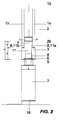
- Figure 1 shows the first embodiment of a glass panel according to this invention in the form of a window and this in a view from the outside of the glass panel.
- the line 1a indicates the outer circumference of the insulating double glass unit of the glazed leaf.
- the line 2b indicates the outer circumference of the distance frame embedded in the insulating glass to create space into which the protrusion 4 of the retaining insert 3 is inserted, what will be described hereinafter.
- the line 3c indicates the outer circumference of the glued retaining insert 3, which retaining insert 3 is arranged around the whole outer circumference of the leaf 10 in this embodiment.
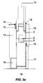
- FIG 2 shows in detail a partial cross-section of an embodiment of the glass panel according to the technical solution shown in Figure 1 .
- the glazed leaf 10 is formed by an insulating double glass unit with two bearing glass panes 1a, 1b, the first bearing glass pane 1a and the second bearing glass pane 1b, separated from each other by a spacer frame 2, which is inserted between them.
- Spacer frame 2 is embedded between both bearing glass panes 1a, 1b by a distance L1, whereby overlaps of both glass panes 11a and 11b are formed. It is appropriate to note that the overlaps 11a and 11b need not be equally long. According to another preferred embodiment (not shown), the exceeding 11a is greater than the exceeding 11b.
- the spacer frame 2 is connected to both bearing glass panes 1a, 1b to form an insulating space between both bearing glass panes similarly as it is the case with conventional insulating glass panes. Therefore, the connection will not be described in detail here.
- a retaining insert 3 of a corresponding shape is inserted, wherein thickness D of the retaining insert 3 is substantially equal to that of the insulating double glass unit, and it is made thinner in this area to form a so called key protrusion 4 of the retaining insert 3 which is glued in the space between the glass panes 1a, 1b.
- this feature is not essential for functioning of the invention.
- any person skilled in the art engaged in design of the insulating glass units is certainly able to suggest a number of functional solutions in which the thickness of the double glass unit will be different from the thickness of the insert.
- additional glass panes with auxiliary spacer frames can be added to the insulating double glass unit (not shown), thus making possible to provide an insulating triple or more glass unit.
- the shape and dimensions of the retaining insert 3 and/or the protrusion 4 are preferably adapted to the so formed insulating glass unit.
- the retaining insert 3 is connected with the first and second bearing glass panes 1a, 1b, and here preferably also with the spacer frame 2, by an adhesive or a putty 8, for example by a butyl based one.
- an adhesive or a putty 8 for example by a butyl based one.
- a forging groove is formed in the retaining insert 3.
- a window fitting 6 is then arranged in the forging groove 5.
- a window fitting 6 also connects the glazed leaf with a fixed frame 7.
- a whole circumferential window fitting is advantageously used as the window fitting 6 in this example of an embodiment, in accordance with the current design of the plastic or wooden windows and doors.
- a standard window handle is used as the control element for the purpose of handling the window fitting, which handle transmits via a transmission mechanism the change in the positions of individual fitting rolls, and the fitting rolls then set by their position the corresponding option for the position of the of the window leaf with regard to the window frame.
- the position may be closed, micro-ventilation, tilting of the leaf, or its opening.
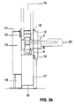
- FIG 3a shows in detail an embodiment of the glass panel according to this technical solution, similarly as in Figure 2 except that in this case the glass panel is also completed with the so called casings which casings have already been mentioned in the previous text.
- the inner casing 12 On the interior side of the glass panel the inner casing 12 is present and on the exterior side the outer casing 13 is present.
- the casings are drawn only generally, however for the full functioning of this embodiment of the glass panel of the present invention they are of important significance.
- the outer casing 13, to which the glazed wing is sealed, is mounted to the fixed frame and this by screwing, gluing or casing into pre-prepared profiles.
- the outer casing 13 is terminated 13 at the height of the inner side of the spacer frame 2.
- Sealing to the outer glass pane of the insulating glass unit is provided with a sealing 15, which sealing 15 can be attached both to the respective glass pane and the outer casing 13.
- the outer casing 13 is then preferably also covered by a protective ledge 14 from above, which ledge 14 is resistant to weathering.
- the inner casing 12 is mounted on the retaining insert 3, and this on its inner, interior side, and this again by screwing, gluing or mounting in pre-prepared profiles.
- sealings 15 are used preferably to achieve a better insulating effect regarding the whole element.
- the inner casing 12 is again terminated at the height of the inner side of the spacer frame.
- the casings can be e.g. of rectangular shape of the profile with different types of chamfered edges, grooves and half-grooves for various additional, sealing and protective devices.
- Profile of the casings may not be firmly fixed, and can be designed according to the needs and requirements imposed upon them.
- the casings may be wooden, from different species of wood and cork, and further also from metal, plastics, pertinax, glass and obviously combined, e. g. sandwiched, from the above listed materials.
- various insulating materials used will certainly be applied here, e. g. various sealing rubber and silicone sealing, materials for active work with moisture such as nano-fibres, etc.
- the casings may provide thermal insulation, humidity, static and aesthetic requirements, and obviously and firstly the functional ones, and so ensure the function of the glass panel according to the invention in accordance with the requirements imposed on them.
- the fixed frame 7 is made of the same material as the retaining insert 3, for example it is of a glued engineering plywood. Preferred is when the frame is lamellary connected by gluing in the corners.
- the width of the fixed frame 7 corresponds to the width of the retaining insert 3 in its free part.
- the counterparts (blocks) 9 for anchoring and fixing of the movable parts of the window fittings are then fixed into this side of the fixed frame 7,.
- the fixed frame 7 is anchored to the walls of the construction hole, eventually also to the sill or to the cap by the so called clamps 18, but the anchoring but can also be made in another suitable manner.
- the various components of the glass panel according to the invention are surface treated adequately before assembly to the building opening, especially when they are of wood.
- a window for construction openings of this technical solution can be used mainly in the construction industry both in the construction of new houses, including the family houses, apartment buildings and offices, as well as in their reconstruction.
Landscapes
- Engineering & Computer Science (AREA)
- Civil Engineering (AREA)
- Structural Engineering (AREA)
- Securing Of Glass Panes Or The Like (AREA)
Applications Claiming Priority (2)
| Application Number | Priority Date | Filing Date | Title |
|---|---|---|---|
| CZ201342 | 2013-01-21 | ||
| CZ2014-43A CZ201443A3 (cs) | 2014-01-20 | 2014-01-20 | Skleněná výplň pro stavební otvor |
Publications (2)
| Publication Number | Publication Date |
|---|---|
| EP2757221A2 true EP2757221A2 (de) | 2014-07-23 |
| EP2757221A3 EP2757221A3 (de) | 2016-11-16 |
Family
ID=50382397
Family Applications (1)
| Application Number | Title | Priority Date | Filing Date |
|---|---|---|---|
| EP14466001.6A Withdrawn EP2757221A3 (de) | 2013-01-21 | 2014-01-21 | Verglasung für eine Gebäudeöffnung |
Country Status (1)
| Country | Link |
|---|---|
| EP (1) | EP2757221A3 (de) |
Citations (3)
| Publication number | Priority date | Publication date | Assignee | Title |
|---|---|---|---|---|
| WO1998002632A1 (de) | 1996-07-11 | 1998-01-22 | Manfred Woschko | Rahmenlose tür- oder fensterflügelanordnung mit isolierverglasung sowie verfahren zu deren herstellung |
| DE19733415A1 (de) | 1996-08-01 | 1998-02-05 | Geze Gmbh & Co | Tür oder Fenster mit schwenkbar gelagertem Flügel |
| EP1020605A2 (de) | 1999-01-18 | 2000-07-19 | GEZE Glas Design GmbH | Rahmenloser Glasflügel als bewegbar gelagerter oder ortsfester Flügel eines Fensters, einer Tür oder einer Fassade oder Glaswand |
Family Cites Families (6)
| Publication number | Priority date | Publication date | Assignee | Title |
|---|---|---|---|---|
| FR2572766A1 (fr) * | 1984-11-08 | 1986-05-09 | Juillet Hubert | Double vitrage a cadre interieur autoportant |
| FR2662739B1 (fr) * | 1990-06-01 | 1992-09-04 | Kirc Pierre | Assemblage de produits verriers sur chassis aluminium, pvc ou autres. |
| BE1008876A3 (nl) * | 1994-11-22 | 1996-08-06 | Quisten Ltd | Beglazingspaneel. |
| IT1278833B1 (it) * | 1995-05-30 | 1997-11-28 | Tosi Flavio Produzione E Monta | Struttura di serramento con vetrocamera |
| DE10011188A1 (de) * | 1999-12-17 | 2001-06-28 | Geze Gmbh | Rahmenloser Glasflügel |
| DE102004027042A1 (de) * | 2003-06-02 | 2005-02-17 | Wolf Galetzki | Isolierglasrahmen |
-
2014
- 2014-01-21 EP EP14466001.6A patent/EP2757221A3/de not_active Withdrawn
Patent Citations (3)
| Publication number | Priority date | Publication date | Assignee | Title |
|---|---|---|---|---|
| WO1998002632A1 (de) | 1996-07-11 | 1998-01-22 | Manfred Woschko | Rahmenlose tür- oder fensterflügelanordnung mit isolierverglasung sowie verfahren zu deren herstellung |
| DE19733415A1 (de) | 1996-08-01 | 1998-02-05 | Geze Gmbh & Co | Tür oder Fenster mit schwenkbar gelagertem Flügel |
| EP1020605A2 (de) | 1999-01-18 | 2000-07-19 | GEZE Glas Design GmbH | Rahmenloser Glasflügel als bewegbar gelagerter oder ortsfester Flügel eines Fensters, einer Tür oder einer Fassade oder Glaswand |
Also Published As
| Publication number | Publication date |
|---|---|
| EP2757221A3 (de) | 2016-11-16 |
Similar Documents
| Publication | Publication Date | Title |
|---|---|---|
| EP3342972B1 (de) | Fenster mit einem flügel und einer verbesserten verbindung mit dem scharnier | |
| EP3103954B1 (de) | Dopperverglasung mit einem vorgespannten kabel im angeformten kantenelement | |
| AU2006224541B2 (en) | Frameless glass door | |
| US10156428B2 (en) | Security door | |
| WO2003072888A2 (en) | Fire-resistant wood assemblies for building | |
| RU2401929C2 (ru) | Рама для окна или двери | |
| US20080256896A1 (en) | Glazing with a Stepped Pane Element Cemented to a Frame | |
| EP2757221A2 (de) | Verglasung für eine Gebäudeöffnung | |
| EP3071775B1 (de) | Unsichtbarer fensterrahmen | |
| ITBZ20090002A1 (it) | Battente a doppio telaio per serramenti esterni con corrispondente infisso. | |
| CN211173810U (zh) | 一种三层复合型保温窗 | |
| WO2008132530A1 (en) | Profile for insulating a window frame | |
| CZ201443A3 (cs) | Skleněná výplň pro stavební otvor | |
| US6301852B1 (en) | Window glazing assembly | |
| EP3060739A1 (de) | Öffnungsfähige rahmenlose tür- oder fensterrahmenanordnung mit isolierverglasung | |
| CN213710828U (zh) | 一种隔热断桥内开内倒窗 | |
| CN213838308U (zh) | 一种单元式铝合金等宽隐扇窗型材结构 | |
| NZ583779A (en) | Window and door frames and sashes lined with insulating thermoplastic layer | |
| KR20220166446A (ko) | 복합 창호 | |
| CN110593715A (zh) | 一种玻璃门密封系统及带有该密封系统的玻璃门 | |
| CA1196530A (en) | Window structures with securely installed window glazing | |
| RU2326223C1 (ru) | Окно из комбинированного профиля | |
| RU59110U1 (ru) | Оконный блок | |
| EP3740640A1 (de) | Rahmenloser flügel mit u-förmigem profil | |
| WO2012121590A1 (en) | Assembly of a leaf and a frame adapted to rotatably receive the leaf |
Legal Events
| Date | Code | Title | Description |
|---|---|---|---|
| PUAI | Public reference made under article 153(3) epc to a published international application that has entered the european phase |
Free format text: ORIGINAL CODE: 0009012 |
|
| 17P | Request for examination filed |
Effective date: 20140121 |
|
| AK | Designated contracting states |
Kind code of ref document: A2 Designated state(s): AL AT BE BG CH CY CZ DE DK EE ES FI FR GB GR HR HU IE IS IT LI LT LU LV MC MK MT NL NO PL PT RO RS SE SI SK SM TR |
|
| AX | Request for extension of the european patent |
Extension state: BA ME |
|
| PUAL | Search report despatched |
Free format text: ORIGINAL CODE: 0009013 |
|
| AK | Designated contracting states |
Kind code of ref document: A3 Designated state(s): AL AT BE BG CH CY CZ DE DK EE ES FI FR GB GR HR HU IE IS IT LI LT LU LV MC MK MT NL NO PL PT RO RS SE SI SK SM TR |
|
| AX | Request for extension of the european patent |
Extension state: BA ME |
|
| RIC1 | Information provided on ipc code assigned before grant |
Ipc: E06B 3/30 20060101ALI20161011BHEP Ipc: E06B 3/24 20060101ALI20161011BHEP Ipc: E06B 3/66 20060101ALI20161011BHEP Ipc: E06B 3/02 20060101AFI20161011BHEP |
|
| STAA | Information on the status of an ep patent application or granted ep patent |
Free format text: STATUS: REQUEST FOR EXAMINATION WAS MADE |
|
| STAA | Information on the status of an ep patent application or granted ep patent |
Free format text: STATUS: THE APPLICATION IS DEEMED TO BE WITHDRAWN |
|
| 18D | Application deemed to be withdrawn |
Effective date: 20170517 |