EP2756748B2 - Einrichtung zum Nachweis eines in eine Erntemaschine eingedrungenen Fremdkörpers - Google Patents
Einrichtung zum Nachweis eines in eine Erntemaschine eingedrungenen Fremdkörpers Download PDFInfo
- Publication number
- EP2756748B2 EP2756748B2 EP14151223.6A EP14151223A EP2756748B2 EP 2756748 B2 EP2756748 B2 EP 2756748B2 EP 14151223 A EP14151223 A EP 14151223A EP 2756748 B2 EP2756748 B2 EP 2756748B2
- Authority
- EP
- European Patent Office
- Prior art keywords
- detection device
- feed roll
- vibration sensor
- signal
- foreign object
- Prior art date
- Legal status (The legal status is an assumption and is not a legal conclusion. Google has not performed a legal analysis and makes no representation as to the accuracy of the status listed.)
- Active
Links
Images



Classifications
-
- A—HUMAN NECESSITIES
- A01—AGRICULTURE; FORESTRY; ANIMAL HUSBANDRY; HUNTING; TRAPPING; FISHING
- A01D—HARVESTING; MOWING
- A01D75/00—Accessories for harvesters or mowers
- A01D75/18—Safety devices for parts of the machines
-
- A—HUMAN NECESSITIES
- A01—AGRICULTURE; FORESTRY; ANIMAL HUSBANDRY; HUNTING; TRAPPING; FISHING
- A01D—HARVESTING; MOWING
- A01D75/00—Accessories for harvesters or mowers
- A01D75/18—Safety devices for parts of the machines
- A01D75/187—Removing foreign objects
Definitions
- the present invention generally relates to a detection device for detection of a foreign object for an agricultural harvesting machine. More specifically such a detection device that is able to detect non-magnetic foreign objects comprising a feed roll assembly for a forage harvester or a combine harvester.
- Detection devices that detect foreign objects based on the effects they cause on a feeder assembly of a harvester have the advantage that upon detection near the feeder assembly the crop flow can be interrupted before the foreign object is further processed along with the crop material by the harvesting machine.
- the detection of it must occur as quickly as possible, as with harvesting machines with increasing productivity the time available for interrupting the crop flow in the feeder assembly before reaching subsequent processing elements is constantly decreased. Furthermore the detection device must operate as reliable as possible being able to detect an as wide range of foreign objects as possible while avoiding false detections interrupting the harvesting operation unnecessarily.
- US5092818 describes a detection device that acoustically detects airborne noise generated by an impact of a foreign object on the feed roll by means of a microphone.
- the microphone needs to be arranged in close vicinity of the impact location and be provided with acoustical isolators. In practice reliable detection is difficult and extensive filtering of the signal is required which leads to detection lags.
- a detection device for detection of a foreign object in an agricultural harvesting machine comprising a feed roll assembly with a central shaft and a feed roll rotatably mounted around the central shaft, the central shaft and the feed roll comprising a common rotational axis.
- the detection device comprises at least one directional vibration sensor and a control system.
- the vibration sensor is mounted on the central shaft such that it can sense vibrations induced into the feed roll assembly.
- the control system is operatively coupled to the vibration sensor and is configured to analyze a signal the vibration sensor and to, based on said analysis, detect whether the foreign object has collided with the feed roller.
- the vibration sensor is mounted such that it senses vibrations induced into the feed roll assembly in a direction transverse to the common rotational axis.
- control system is further configured to: analyze the signal generated by the vibration sensor by:
- the central shaft comprises near its axial extremities two supports for mounting the feed roll assembly to the harvesting machine, and at least one vibration sensor is mounted on the central shaft in between the two supports. This allows for a simple mounting of the vibration sensor.
- the vibration sensor is mounted on the central shaft and inside the feed roll. This shields it from moisture and dust.
- the predetermined sample rate and the predetermined number of consecutive samples are related to a predetermined maximum delay for detection, in such a way that a quotient of the predetermined number of consecutive samples and the predetermined sample rate substantially corresponds to the predetermined maximum delay for detection.
- the sampling rate and the predetermined number of consecutive samples are determined such that a summed, squared sampled signal generated by the collision of the foreign object is maximized.
- the predetermined number of consecutive samples is equal to about the main frequency component of the signal generated by the collision of the foreign object divided by the predetermined sampling rate.
- control system is further configured to receive an operating parameter of the harvesting machine; and the predetermined threshold is determined in function of the operating parameter of the harvesting machine.
- the operating parameter of the harvesting machine is one or more of the following: rotational speed of the feed roll, type of crop being harvested, installed components on the harvesting machine, such as for example, the type of header used, the number and type of knives installed on the cutter drum of a forage harvester, and/or cutting length for the crop when harvested by a forage harvester.
- the detection device comprises the at least one sensor being mounted on the feed roll comprising a piezoelectric vibration sensor, the control system comprising a first part being mounted on the feed roll and comprising, a wireless transmitter configured to transmit a wireless signal generated by the control system on the basis of the signal generated by the vibration sensor and a local power source for providing power to the wireless transmitter, and the control system further comprising a second part being mounted on the central shaft comprising a wireless receiver configured to receive the wireless signal.
- the local power source allows for local processing of the vibration sensor signal rotating on the feed roll, which subsequently allows to transmit a digital signal wirelessly without an increase in detection lag, nor the risk of sensor signal degradation.
- the wireless signal is only generated when the control system detects the collision of the foreign object. This optimizes power consumption of the local power source.
- the local power source is a rechargeable power source and is configured to be recharged by means a recharging means providing an inductive power coupling between the first part and the second part of the control system.
- a method for detecting a foreign object with a detection device characterized in that it comprises the steps of: analyzing the signal generated by the vibration sensor by:
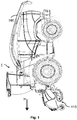
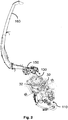
- FIG. 1 and 2 schematically show a forage harvester 1 comprising a detection device according to the invention.
- the forage harvester 1 travels along a direction V along a field and picks up crop, such as for example grass, by means of a pick-up mechanism 110.
- the crop is subsequently transported to a feeder which comprises a plurality of feeder rolls 32 which are driven to transport the crop at a controlled rate to the cutter drum 130 which cooperates with a fixed knife in order to chop the crop in pieces of a predetermined length.
- the crop is propelled by means of a fan element 150 towards a spout 160 for directing it into a suitable reservoir such as a cart pulled by a tractor for further transportation to a storage location.
- the detection device according to the invention is mounted into a feed roll assembly 30 which comprises a feed roll 32 of the feeder.
- a feed roll 32 of the feeder For the forage harvester shown in Figure 1 , preferably the lower front feed roll 32 is chosen as this is the feed roll that is most likely to come into contact with a foreign object when crop material is being harvested.
- the detection device could also be used in combination with alternative mechanisms for taking up crop. For example maize headers, grain headers, etc. could be attached to the forage harvester 1 and other types of harvesters such as for example combine harvesters, pull type forage harvesters, etc.
- FIG 3 shows a sectional view according to the line III-III in Figure 2 of the detection device for detection of a foreign object for an agricultural harvesting machine 1 in more detail.
- the detection device comprises the feed roll assembly 30, which comprises a central shaft 34. Around this central shaft 34 a feed roll 32 is rotatably mounted. According to the embodiment shown the feed roll 32 is mounted to the central shaft 34 by means of suitable flanges 36 at both opposite sides of the feed roll 32 which are connected to suitable bearings 38 which rotatably connect these flanges to the central shaft 34. The rotational axes of these bearings 38 are aligned and coincide with the rotational axis 40 of the feed roll 32.
- the rotational axis of the feed roll 32 is substantially parallel to the longitudinal axis of the central shaft 34.
- At least one of these flanges 36 is provided with suitable means 37 for coupling the flange 36 to a drive system, which when mounted into an agricultural vehicle can rotatably drive the feed roll 32 around the central shaft 34, this central shaft then at both longitudinal ends being supported on the frame of the agricultural harvester 1 by means of suitable supports.
- the detection device comprises at least one vibration sensor 20.
- vibration sensors 20 are mounted on the feed roll assembly 30 such that it can sense vibrations induced into the feed roll assembly 30, especially vibrations generated by impact of a foreign object, such as for example a stone, on the feed roll assembly 30.
- vibration sensor 20 could for example be a piezoelectric vibration sensor or any other type of suitable directional vibration sensor.
- the vibration sensors 20 are mounted on the central shaft 34.
- the vibration sensors 20 could be mounted both on the feed roll 32 and the central shaft 34. It is not required to mount a plurality of vibration sensors 20, according to some embodiments a single vibration sensor 20 could suffice.
- the feed roll 32 is formed by a substantially cylindrical, metal plate, which is provided with longitudinal slats 33 in order to increase friction on the crop material.
- the feed roll 32 could be for example manufactured from stainless steel.
- Equally also the other elements of the feed roll assembly 30 may be manufactured from a suitable metal such as stainless steel.
- the amount of deflection of the feed roll 32 or the central shaft 34 depends, amongst other things, on the stiffness of the structure, the direction of the impact force, the location of the impact force. It was found that the deflection of the feed roll 32 or the central shaft 34 along the transverse direction 41 is larger than that along the longitudinal direction which is substantially aligned with the rotational axis 40.
- the vibration sensors 20 are mounted such that they sense vibrations induced into the feed roll assembly 30 in the direction 41 transverse to the rotational axis 40 of said feed roll 32. In this way the vibrations, which correspond to the largest deflections will result in the largest accelerations that are measured by the vibration sensor 20 in order to provide a clear signal for the detection of an impact.
- the vibration sensor 20 is preferably mounted inside the feed roll 32 so that it is shielded from for example moisture and dust generated by the harvesting process. Furthermore in this way the vibration sensor 20 is mounted close to the source of the vibrations generated by an impact of a foreign object on the feed roll 32. The deflection along the transverse direction during the vibrations generated by an impact on the feed roll 32 will become smaller for locations on the feed roll assembly 30 closer to the supports for mounting said feed roll assembly 30 to said harvesting machine 1 near the axial extremities of the central shaft 34. Therefore, according to the embodiment shown in Figures 2-5 , the vibration sensors 20 that are mounted on the central shaft 34 in between these supports, are preferably mounted in an axial mounting zone 74 comprising the center 76 between these supports.
- this axial mounting zone 74 extends axially over a distance smaller than the distance between these two supports, however according to a specific embodiment it could be a relatively small zone around the center 76 between both supports where the transverse deflection of the feeder roll 32 or the central shaft is likely to be sufficiently large for detection by a vibration sensor 20.
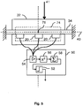
- control system 50 in general is configured to analyze the signal generated by the one or more vibration sensors 20 by sampling 54 this signal at a predetermined sample rate, calculating the square 56 of this sampled signal and subsequently integrating the squared signal 56 or calculating the sum 58 of a predetermined number consecutive samples of said squared sampled signal 56.
- the collision of the foreign object is then detected when the summed, squared sampled signal 58 exceeds a predetermined threshold 65.
- this predetermined threshold could for example be a factory set parameter.
- the impact of foreign objects generate acceleration signals as measured by the vibration sensor 20 with as characteristics a main frequency component in the range of 80Hz to 200Hz, for example 120Hz.
- the acceleration signals are further largely sinusoidal in shape, which means that the vibrations manifest themselves at the location of the vibration sensor 20 as a sequence of acceleration phases immediately followed by similar deceleration phases in contrast to disturbance spikes which typically result in only a positive or negative specific deflection of the signal.
- squaring the sampled signal and subsequently summing a predetermined number of consecutive squared samples results in a clear discrimination of the signal generated by an impact of a foreign object versus a spike in the signal generated by a disturbance.
- the predetermined number of samples can be performed in a simple way for a specific sampling rate if the main frequency component of the signal generated by the collision of a foreign object is known. For example as when the sampling rate is 1 kHz and the main frequency component is 120Hz, this predetermined number of samples can be chosen to be equal to about the main frequency component of said signal generated by said collision of said foreign object divided by said predetermined sampling rate, which is in this particular case 120Hz / 1kHz which results in about 9 samples.
- the predetermined threshold 65 could be manually adjusted by an operator to be able to cope with varying harvesting conditions.
- the control system 50 could also be configured to receive an operating parameter of the harvesting machine 1; such as for example the rotational speed of the feed roll, the type of crop being harvested, installed components on the harvesting machine, such as for example the type of header used, the number and type of knives installed on the cutter drum of a forage harvester, the cutting length for the crop when harvested by a forage harvester, harvesting conditions, etc. so that this predetermined threshold can be set to a value that allows the most reliable detection of a foreign object in the specific situation.
- the control system 50 comprises two parts.
- a first part is also mounted on the feed roll 32 and comprises a wireless transmitter configured to transmit a wireless signal generated on the basis of the signal generated by said vibration sensor 20.
- the first part of the controls system comprises a local power source.
- a second part of the control system 50 is mounted on the central shaft 34 and comprises a wireless receiver configured to receive the wireless signal transmitted by the wireless transmitter.
- vibration sensors could be arranged on the feed roll 32, which could be distributed along the longitudinal axis or around the cylindrical circumference of the feed roll 32 in order to optimize detection of foreign object impacts along the entire circumference of the feed roll.
- the control system 50 converts the analog signal from the vibration sensor 20 to a suitable digital signal before wireless transmission, so that the quality of the signal is not degraded by the wireless transmission and a reliable detection is possible.
- the vibration sensor 20 is preferably a piezoelectric vibration sensor.
- piezoelectric vibration sensors such as for example the known types of Bosch with reference number 0 261 231 196, are able to detect vibrations in the desired frequency range and are furthermore able to generate a signal without consuming power from a power source.
- the operation of the wireless transmitter may be optimized by only generating the wireless signal when the first part of the control system 50 detects a collision of said foreign object.
- this means In order to do so the processing of the signal 54 from the vibration sensor 20, this means, detecting when the summed, squared signal 58 exceeds the predetermined threshold 65 in order to produce a detection signal 52 must be executed locally in the first part 62 of the control system.
- the local power source can comprise a rechargeable power source, such as for example a rechargeable battery.
- This rechargeable power source can then be recharged by means of an inductive power coupling between the first part and the second part of the control system 50 as schematically illustrated.
- top, bottom, over, under, and the like are introduced for descriptive purposes and not necessarily to denote relative positions. It is to be understood that the terms so used are interchangeable under appropriate circumstances and embodiments of the invention are capable of operating according to the present invention in other sequences, or in orientations different from the one(s) described or illustrated above.
Landscapes
- Life Sciences & Earth Sciences (AREA)
- Environmental Sciences (AREA)
- Measurement Of Mechanical Vibrations Or Ultrasonic Waves (AREA)
Claims (12)
- Eine Detektions-Einrichtung zur Detektion eines Fremdkörpers in einer landwirtschaftlichen Erntemaschine (1),
wobei die Erntemaschine (1) eine Zuführungswalzen-Anordnung (30) mit einer zentralen Welle (34) und einer Zuführungswalze (32) umfasst, die drehbar um die zentrale Welle (34) herum befestigt ist, wobei die zentrale Welle (34) und die Zuführungswalze (32) eine gemeinsame Drehachse (40) umfassen,
wobei die Detektions-Einrichtung Folgendes umfasst:- zumindest einen eine Richtwirkung aufweisenden Schwingungssensor (20), der auf der zentralen Welle (34) derart befestigt ist, dass er in der Zuführungswalzen-Anordnung (30) hervorgerufene Schwingungen messen kann; und- ein Steuersystem (50), das betriebsmäßig mit dem Schwingungssensor (20) verbunden ist und so konfiguriert ist, dass es:dadurch gekennzeichnet, dass:- ein von dem Schwingungssensor (20) erzeugtes Signal analysiert, und- auf der Grundlage dieser Analyse feststellt, ob der Fremdkörper mit der Zuführungswalze (32) zusammengestoßen ist,
der Schwingungssensor (20) derart befestigt ist, dass er in der Zuführungswalzen-Anordnung (30) induzierte Schwingungen in einer Richtung (41) quer zur gemeinsamen Drehachse (40) misst und das Steuersystem (50) weiterhin so konfiguriert ist, dass es:- das von dem Schwingungssensor (20) erzeugte Signal dadurch analysiert, dass es:- ein abgetastetes Signal (54) durch Abtasten des von dem Schwingungssensor (20) erzeugten Signals mit einer vorgegebenen Abtastrate erzeugt;- ein quadriertes abgetastetes Signal (56) als das Quadrat des abgetasteten Signals (54) berechnet;- ein summiertes quadriertes abgetastetes Signal (58) als die Summe einer vorgegebenen Anzahl von aufeinanderfolgenden Abtastproben des quadrierten abgetasteten Signals berechnet; und- ein Detektionssignal (52) erzeugt, wenn das summierte, quadrierte, abgetastete Signal (58) einen vorgegebenen Schwellenwert (65) übersteigt, um einen Zusammenprall mit einem Fremdkörper festzustellen. - Eine Detektions-Einrichtung nach Anspruch 1, dadurch gekennzeichnet,
dass die zentrale Welle (34) in der Nähe ihrer Enden zwei Lager zur Befestigung der Zuführungswalzen-Anordnung (30) an der Erntemaschine (1) umfasst, und
dass zumindest ein Schwingungssensor (20) auf der zentralen Welle (34) zwischen den zwei Lagern befestigt ist. - Eine Detektions-Einrichtung nach Anspruch 2, dadurch gekennzeichnet, dass die vorgegebene Abtastrate und die vorgegebene Anzahl von aufeinanderfolgenden Abtastproben auf eine vorgegebene maximale Detektions-Verzögerung bezogen sind, derart, dass ein Quotient der vorgegebenen Anzahl von aufeinanderfolgenden Abtastproben und der vorgegebenen Abtastrate im Wesentlichen der vorgegebenen maximalen Detektions-Verzögerung entspricht.
- Eine Detektions-Einrichtung nach Anspruch 1 oder 2, dadurch gekennzeichnet, dass die Abtastrate und die vorgegebene Anzahl von aufeinanderfolgenden Abtastproben derart bestimmt sind, dass ein summiertes, quadriertes abgetastetes Signal (58), das durch den Aufprall des Fremdkörpers erzeugt wird, zu einem Maximum gemacht wird.
- Eine Detektions-Einrichtung nach Anspruch 4, dadurch gekennzeichnet, dass die vorgegebene Anzahl von aufeinanderfolgenden Abtastproben angenähert gleich der Haupt-Frequenzkomponente des Signals, das durch den Aufprall des Femdkörpers erzeugt wird, dividiert durch die vorgegebene Abtastrate ist.
- Eine Detektions-Einrichtung nach einem der Ansprüche 1 bis 5, dadurch gekennzeichnet, dass das Steuersystem (50) weiterhin so konfiguriert ist, dass es einen Betriebsparameter der Erntemaschine (1) empfängt, und dass der vorgegebene Schwellenwert (65) als Funktion des Betriebsparameters der Erntemaschine (1) bestimmt wird.
- Eine Detektions-Einrichtung nach Anspruch 6, dadurch gekennzeichnet, dass der Betriebsparameter der Erntemaschine (1) einer von Folgendem ist:- Drehgeschwindigkeit der Zuführungswalze;- Typ des Erntematerials, das geerntet wird;- installierte Komponenten auf der Erntemaschine, wie zum Beispiel der Typ des Vorsatzgerätes, das verwendet wird, die Anzahl und Art der Messer, die auf der Messertrommel eines Feldhäckslers installiert sind; und/oder- die Schneidlänge für das Erntematerial, wenn es von einem Feldhäcksler geerntet wird.
- Eine Detektions-Einrichtung nach einem der vorhergehenden Ansprüche, dadurch gekennzeichnet, dass die Detektions-Einrichtung Folgendes umfasst:- zumindest einen zusätzlichen Sensor (20), der auf der Zuführungswalze (32) befestigt ist;- wobei das Steuersystem (50) einen ersten Teil umfasst, der auf der Zuführungswalze (32) befestigt ist und Folgendes umfasst:- einen drahtlosen Sender, der zum Senden eines drahtlosen Signals konfiguriert ist, das von dem Steuersystem (50) auf der Grundlage des Signals erzeugt wird, das von dem Schwingungssensor (20) erzeugt wird; und- eine örtliche Leistungsquelle zur Lieferung von Leistung an den drahtlosen Sender; und- das Steuersystem (50) weiterhin einen zweiten Teil umfasst, der auf der zentralen Welle (34) befestigt ist und einen drahtlosen Empfänger umfasst, der zum Empfang des drahtlosen Signals konfiguriert ist.
- Eine Detektions-Einrichtung nach Anspruch 8, dadurch gekennzeichnet, dass das drahtlose Signal lediglich dann erzeugt wird, wenn das Steuersystem (50) den Aufprall des Fremdkörpers erfasst.
- Eine Detektions-Einrichtung nach Anspruch 8 oder 9, dadurch gekennzeichnet, dass die örtliche Leistungsquelle eine wiederaufladbare Leistungsquelle ist und so konfiguriert ist, dass sie mit Hilfe einer Wiederauflade-Einrichtung wieder aufgeladen wird, die eine induktive Leistungskopplung (70) zwischen dem ersten Teil und dem zweiten Teil des Steuersystems (50) bereitstellt.
- Eine Detektions-Einrichtung nach einem der vorhergehenden Ansprüche, bei dem der Schwingungssensor (20) ein Klopfsensor ist.
- Ein Verfahren zur Detektion eines Fremdkörpers mit einer Detektions-Einrichtung nach einem der vorhergehenden Ansprüche, dadurch gekennzeichnet, dass das Verfahren die folgenden Schritte umfasst:- Analysieren des von dem Schwingungssensor (20) erzeugten Signals durch:- Bestimmen eines vorgegebenen Schwellenwertes (65);- Erzeugen eines abgetasteten Signals (54) durch Abtasten des durch den Schwingungssensor (20) erzeugten Signals mit einer vorgegebenen Abtastrate;- Berechnen eines quadrierten abgetasteten Signals (56) als das Quadrat des abgetasteten Signals (54);- Berechnen eines summierten quadrierten abgetasteten Signals (58) als die Summe einer vorgegebenen Anzahl von aufeinanderfolgenden Abtastproben des quadrierten abgetasteten Signals, und- Erzeugen eines Detektionssignals (52), wenn das summierte, quadrierte, abgetastete Signal (58) den vorgegebenen Schwellenwert (65) übersteigt, um einen Aufprall eines Fremdkörpers zu erfassen.
Applications Claiming Priority (1)
| Application Number | Priority Date | Filing Date | Title |
|---|---|---|---|
| BE2013/0035A BE1021124B1 (nl) | 2013-01-18 | 2013-01-18 | Detectietoestel voor het detecteren van een vreemd voorwerp voor een oogstmachine. |
Publications (3)
| Publication Number | Publication Date |
|---|---|
| EP2756748A1 EP2756748A1 (de) | 2014-07-23 |
| EP2756748B1 EP2756748B1 (de) | 2015-08-19 |
| EP2756748B2 true EP2756748B2 (de) | 2018-06-06 |
Family
ID=48092629
Family Applications (1)
| Application Number | Title | Priority Date | Filing Date |
|---|---|---|---|
| EP14151223.6A Active EP2756748B2 (de) | 2013-01-18 | 2014-01-15 | Einrichtung zum Nachweis eines in eine Erntemaschine eingedrungenen Fremdkörpers |
Country Status (3)
| Country | Link |
|---|---|
| US (1) | US9668421B2 (de) |
| EP (1) | EP2756748B2 (de) |
| BE (1) | BE1021124B1 (de) |
Families Citing this family (8)
| Publication number | Priority date | Publication date | Assignee | Title |
|---|---|---|---|---|
| DE102013201618A1 (de) * | 2013-01-31 | 2014-07-31 | Deere & Company | Schwingungsaufnehmereinheit |
| US10271115B2 (en) * | 2015-04-08 | 2019-04-23 | Itt Manufacturing Enterprises Llc. | Nodal dynamic data acquisition and dissemination |
| PL234277B1 (pl) * | 2017-01-27 | 2020-01-31 | Int Tobacco Machinery Poland Spolka Z Ograniczona Odpowiedzialnoscia | Urządzenie tnące przemysłu tytoniowego, oraz sposób wykrywania uszkodzeń noża tnącego w przemyśle tytoniowym |
| SI25432A (sl) * | 2017-05-08 | 2018-11-30 | Branko Kos | Naprava in postopek za nadzorovanje vibracij na kmetijskem stroju, kot je mulčer |
| US10820468B2 (en) * | 2018-09-19 | 2020-11-03 | Cnh Industrial America Llc | System and method for determining soil roughness of a field across which an agricultural implement is being moved based on ground engaging tool acceleration |
| NL2023209B1 (nl) * | 2019-05-27 | 2020-12-02 | Ploeger Oxbo Europe B V | Inrichting die verplaatsbaar is in een rijrichting over een met behulp van de inrichting te bewerken land alsmede zelfrijdende landbouwmachine |
| WO2022161748A1 (en) | 2021-01-27 | 2022-08-04 | Zf Cv Systems Global Gmbh | Operational safety of a agricultural implement |
| DE102024108699A1 (de) * | 2024-03-27 | 2025-10-02 | Claas Selbstfahrende Erntemaschinen Gmbh | Landwirtschaftliche Erntemaschine |
Citations (4)
| Publication number | Priority date | Publication date | Assignee | Title |
|---|---|---|---|---|
| US4353199A (en) † | 1981-04-15 | 1982-10-12 | Sperry Corporation | Stone detector for harvesting machines |
| DE102006033100A1 (de) † | 2005-07-14 | 2007-01-25 | Deere & Company, Moline | Einrichtung zum Nachweis eventuell von einer Erntegutaufnahmeeinrichtung aufgenommener Fremdkörper |
| DE102009000351B4 (de) † | 2009-01-21 | 2011-05-19 | Deere & Company, Moline | Schwingungsaufnehmereinheit |
| EP2514299A1 (de) † | 2011-04-21 | 2012-10-24 | Deere & Company | Einrichtung zum Nachweis eines in eine Erntemaschine eingedrungenen Fremdkörpers |
Family Cites Families (20)
| Publication number | Priority date | Publication date | Assignee | Title |
|---|---|---|---|---|
| US3559805A (en) * | 1968-07-02 | 1971-02-02 | Patricia A Cragg | Stone and rock removing device |
| US4275546A (en) * | 1980-01-04 | 1981-06-30 | Sperry Corporation | Stone discriminator |
| US4464935A (en) * | 1983-05-09 | 1984-08-14 | General Electric Company | Shaft vibration evaluation |
| DE3577637D1 (de) | 1984-02-14 | 1990-06-21 | Nat Res Dev | Vorrichtung zum aufnehmen und foerdern von erntegut oder anderem material. |
| DD247117A3 (de) | 1985-10-04 | 1987-07-01 | Fortschritt Veb K | Verfahren zum erkennen von fremdkoerpern in landwirtschaftlichen erntemaschinen |
| US5092818A (en) * | 1990-10-26 | 1992-03-03 | Ford New Holland, Inc. | Metal and hard object detectors with shared fixed support inside a feed roll |
| US5078645A (en) | 1990-10-26 | 1992-01-07 | Ford New Holland, Inc. | Method and apparatus for hard object detection |
| DE19854562A1 (de) | 1998-11-26 | 2000-05-31 | Claas Saulgau Gmbh | Einrichtung zur Überwachung der Einzugsbaugruppe einer landwirtschaftlichen Erntemaschine |
| DE19904626C2 (de) | 1999-02-05 | 2001-05-17 | Case Harvesting Sys Gmbh | Verfahren zum Erkennen von Fremdkörpern in Erntemaschinen |
| DE10100521A1 (de) | 2001-01-08 | 2002-07-11 | Deere & Co | Überwachungseinrichtung für eine Erntemaschine |
| US6637179B2 (en) * | 2001-12-20 | 2003-10-28 | Kasha Farm Supplies Ltd. | Inertial system for detecting foreign objects between contra-rotating rolls |
| US6601372B1 (en) * | 2002-02-22 | 2003-08-05 | New Holland North America, Inc. | Stone detection method and apparatus for harvester |
| DE102004035928A1 (de) | 2004-07-23 | 2006-03-16 | Claas Selbstfahrende Erntemaschinen Gmbh | Schutzvorrichtung für landwirtschaftliche Arbeitsmaschinen |
| US20060277883A1 (en) * | 2005-06-10 | 2006-12-14 | Berger John G | Acoustic stone detection for a feederhouse on an agricultural combine |
| US7520111B2 (en) * | 2005-06-10 | 2009-04-21 | Cnh America Llc | Stone detection method and apparatus for a harvester |
| GB0604860D0 (en) * | 2006-03-10 | 2006-04-19 | Cnh Belgium Nv | Improvements in or relating to material stream sensors |
| DE102006015152A1 (de) * | 2006-03-30 | 2008-09-25 | Claas Selbstfahrende Erntemaschinen Gmbh | Körperschallsensoreinheit |
| GB2438578A (en) * | 2006-05-30 | 2007-12-05 | Cnh Belgium Nv | Metal object detection system for harvester |
| DE102008054488B4 (de) * | 2008-12-10 | 2020-10-22 | Deere & Company | Einrichtung zum Nachweis eines in eine Erntemaschine eingedrungenen Fremdkörpers |
| DE102012109393A1 (de) * | 2012-10-02 | 2014-04-03 | Prüftechnik Dieter Busch AG | Vorrichtung und Verfahren zur Bewertung von Schwingungen |
-
2013
- 2013-01-18 BE BE2013/0035A patent/BE1021124B1/nl active
-
2014
- 2014-01-15 EP EP14151223.6A patent/EP2756748B2/de active Active
- 2014-01-16 US US14/157,223 patent/US9668421B2/en not_active Expired - Fee Related
Patent Citations (4)
| Publication number | Priority date | Publication date | Assignee | Title |
|---|---|---|---|---|
| US4353199A (en) † | 1981-04-15 | 1982-10-12 | Sperry Corporation | Stone detector for harvesting machines |
| DE102006033100A1 (de) † | 2005-07-14 | 2007-01-25 | Deere & Company, Moline | Einrichtung zum Nachweis eventuell von einer Erntegutaufnahmeeinrichtung aufgenommener Fremdkörper |
| DE102009000351B4 (de) † | 2009-01-21 | 2011-05-19 | Deere & Company, Moline | Schwingungsaufnehmereinheit |
| EP2514299A1 (de) † | 2011-04-21 | 2012-10-24 | Deere & Company | Einrichtung zum Nachweis eines in eine Erntemaschine eingedrungenen Fremdkörpers |
Also Published As
| Publication number | Publication date |
|---|---|
| BE1021124B1 (nl) | 2016-01-11 |
| EP2756748B1 (de) | 2015-08-19 |
| EP2756748A1 (de) | 2014-07-23 |
| US9668421B2 (en) | 2017-06-06 |
| US20140202126A1 (en) | 2014-07-24 |
Similar Documents
| Publication | Publication Date | Title |
|---|---|---|
| EP2756748B2 (de) | Einrichtung zum Nachweis eines in eine Erntemaschine eingedrungenen Fremdkörpers | |
| US7415365B2 (en) | Structure-borne sound sensor unit | |
| US12604810B2 (en) | Systems, apparatus, and related methods for use with mergers | |
| CN107135735B (zh) | 收获机和供收获机用的控制系统 | |
| CN103975709B (zh) | 农业收割机、尤其是田地粉碎机 | |
| US9125342B2 (en) | Method and device for the state detection of a cutting device | |
| US4353199A (en) | Stone detector for harvesting machines | |
| US6886314B2 (en) | Device for measuring and/or checking the distance between a shear bar and a chopping knife | |
| BE1019497A5 (fr) | Dispositif de mise en evidence d'un corps etranger ayant penetre dans une machine de recolte. | |
| CN110996652B (zh) | 收割作业区域确定装置 | |
| EP4104662B1 (de) | Schneidvorrichtung | |
| US20200359563A1 (en) | Driver assistance system of a forage harvester | |
| EP4088560B1 (de) | Kornverlustmessung | |
| EA018276B1 (ru) | Блок детектора механических колебаний | |
| US5092818A (en) | Metal and hard object detectors with shared fixed support inside a feed roll | |
| US10462967B2 (en) | Measuring device for measuring a mass flow composed of bulk material | |
| US4720963A (en) | Method of detecting stones in the intake of a field chopper | |
| US20060277883A1 (en) | Acoustic stone detection for a feederhouse on an agricultural combine | |
| EA023115B1 (ru) | Устройство для обнаружения попавшего в уборочную машину инородного тела | |
| US5070682A (en) | Acoustic detector with start-up control | |
| US7523599B2 (en) | Method and device for adjusting the sensitivity of a foreign-object detection device | |
| US5078645A (en) | Method and apparatus for hard object detection | |
| US9089091B2 (en) | Method and system for controlling an operating parameter of a harvesting machine | |
| EP1731019B1 (de) | Akustische Detektion von Steinen für ein Schrägfördergehäuse eines Mähdreschers | |
| JP7042630B2 (ja) | コンバイン |
Legal Events
| Date | Code | Title | Description |
|---|---|---|---|
| PUAI | Public reference made under article 153(3) epc to a published international application that has entered the european phase |
Free format text: ORIGINAL CODE: 0009012 |
|
| 17P | Request for examination filed |
Effective date: 20140115 |
|
| AK | Designated contracting states |
Kind code of ref document: A1 Designated state(s): AL AT BE BG CH CY CZ DE DK EE ES FI FR GB GR HR HU IE IS IT LI LT LU LV MC MK MT NL NO PL PT RO RS SE SI SK SM TR |
|
| AX | Request for extension of the european patent |
Extension state: BA ME |
|
| R17P | Request for examination filed (corrected) |
Effective date: 20150123 |
|
| RBV | Designated contracting states (corrected) |
Designated state(s): AL AT BE BG CH CY CZ DE DK EE ES FI FR GB GR HR HU IE IS IT LI LT LU LV MC MK MT NL NO PL PT RO RS SE SI SK SM TR |
|
| GRAP | Despatch of communication of intention to grant a patent |
Free format text: ORIGINAL CODE: EPIDOSNIGR1 |
|
| RIC1 | Information provided on ipc code assigned before grant |
Ipc: A01D 75/18 20060101AFI20150227BHEP |
|
| INTG | Intention to grant announced |
Effective date: 20150318 |
|
| GRAS | Grant fee paid |
Free format text: ORIGINAL CODE: EPIDOSNIGR3 |
|
| GRAA | (expected) grant |
Free format text: ORIGINAL CODE: 0009210 |
|
| AK | Designated contracting states |
Kind code of ref document: B1 Designated state(s): AL AT BE BG CH CY CZ DE DK EE ES FI FR GB GR HR HU IE IS IT LI LT LU LV MC MK MT NL NO PL PT RO RS SE SI SK SM TR |
|
| REG | Reference to a national code |
Ref country code: GB Ref legal event code: FG4D |
|
| REG | Reference to a national code |
Ref country code: CH Ref legal event code: EP |
|
| REG | Reference to a national code |
Ref country code: IE Ref legal event code: FG4D |
|
| REG | Reference to a national code |
Ref country code: AT Ref legal event code: REF Ref document number: 743118 Country of ref document: AT Kind code of ref document: T Effective date: 20150915 |
|
| REG | Reference to a national code |
Ref country code: DE Ref legal event code: R096 Ref document number: 602014000140 Country of ref document: DE |
|
| REG | Reference to a national code |
Ref country code: FR Ref legal event code: PLFP Year of fee payment: 3 |
|
| REG | Reference to a national code |
Ref country code: AT Ref legal event code: MK05 Ref document number: 743118 Country of ref document: AT Kind code of ref document: T Effective date: 20150819 |
|
| REG | Reference to a national code |
Ref country code: LT Ref legal event code: MG4D |
|
| REG | Reference to a national code |
Ref country code: NL Ref legal event code: MP Effective date: 20150819 |
|
| PG25 | Lapsed in a contracting state [announced via postgrant information from national office to epo] |
Ref country code: LV Free format text: LAPSE BECAUSE OF FAILURE TO SUBMIT A TRANSLATION OF THE DESCRIPTION OR TO PAY THE FEE WITHIN THE PRESCRIBED TIME-LIMIT Effective date: 20150819 Ref country code: LT Free format text: LAPSE BECAUSE OF FAILURE TO SUBMIT A TRANSLATION OF THE DESCRIPTION OR TO PAY THE FEE WITHIN THE PRESCRIBED TIME-LIMIT Effective date: 20150819 Ref country code: FI Free format text: LAPSE BECAUSE OF FAILURE TO SUBMIT A TRANSLATION OF THE DESCRIPTION OR TO PAY THE FEE WITHIN THE PRESCRIBED TIME-LIMIT Effective date: 20150819 Ref country code: NO Free format text: LAPSE BECAUSE OF FAILURE TO SUBMIT A TRANSLATION OF THE DESCRIPTION OR TO PAY THE FEE WITHIN THE PRESCRIBED TIME-LIMIT Effective date: 20151119 Ref country code: GR Free format text: LAPSE BECAUSE OF FAILURE TO SUBMIT A TRANSLATION OF THE DESCRIPTION OR TO PAY THE FEE WITHIN THE PRESCRIBED TIME-LIMIT Effective date: 20151120 |
|
| PG25 | Lapsed in a contracting state [announced via postgrant information from national office to epo] |
Ref country code: IS Free format text: LAPSE BECAUSE OF FAILURE TO SUBMIT A TRANSLATION OF THE DESCRIPTION OR TO PAY THE FEE WITHIN THE PRESCRIBED TIME-LIMIT Effective date: 20151219 Ref country code: ES Free format text: LAPSE BECAUSE OF FAILURE TO SUBMIT A TRANSLATION OF THE DESCRIPTION OR TO PAY THE FEE WITHIN THE PRESCRIBED TIME-LIMIT Effective date: 20150819 Ref country code: SE Free format text: LAPSE BECAUSE OF FAILURE TO SUBMIT A TRANSLATION OF THE DESCRIPTION OR TO PAY THE FEE WITHIN THE PRESCRIBED TIME-LIMIT Effective date: 20150819 Ref country code: PT Free format text: LAPSE BECAUSE OF FAILURE TO SUBMIT A TRANSLATION OF THE DESCRIPTION OR TO PAY THE FEE WITHIN THE PRESCRIBED TIME-LIMIT Effective date: 20151221 Ref country code: AT Free format text: LAPSE BECAUSE OF FAILURE TO SUBMIT A TRANSLATION OF THE DESCRIPTION OR TO PAY THE FEE WITHIN THE PRESCRIBED TIME-LIMIT Effective date: 20150819 Ref country code: PL Free format text: LAPSE BECAUSE OF FAILURE TO SUBMIT A TRANSLATION OF THE DESCRIPTION OR TO PAY THE FEE WITHIN THE PRESCRIBED TIME-LIMIT Effective date: 20150819 Ref country code: RS Free format text: LAPSE BECAUSE OF FAILURE TO SUBMIT A TRANSLATION OF THE DESCRIPTION OR TO PAY THE FEE WITHIN THE PRESCRIBED TIME-LIMIT Effective date: 20150819 |
|
| PG25 | Lapsed in a contracting state [announced via postgrant information from national office to epo] |
Ref country code: NL Free format text: LAPSE BECAUSE OF FAILURE TO SUBMIT A TRANSLATION OF THE DESCRIPTION OR TO PAY THE FEE WITHIN THE PRESCRIBED TIME-LIMIT Effective date: 20150819 |
|
| PG25 | Lapsed in a contracting state [announced via postgrant information from national office to epo] |
Ref country code: EE Free format text: LAPSE BECAUSE OF FAILURE TO SUBMIT A TRANSLATION OF THE DESCRIPTION OR TO PAY THE FEE WITHIN THE PRESCRIBED TIME-LIMIT Effective date: 20150819 Ref country code: SK Free format text: LAPSE BECAUSE OF FAILURE TO SUBMIT A TRANSLATION OF THE DESCRIPTION OR TO PAY THE FEE WITHIN THE PRESCRIBED TIME-LIMIT Effective date: 20150819 Ref country code: DK Free format text: LAPSE BECAUSE OF FAILURE TO SUBMIT A TRANSLATION OF THE DESCRIPTION OR TO PAY THE FEE WITHIN THE PRESCRIBED TIME-LIMIT Effective date: 20150819 Ref country code: CZ Free format text: LAPSE BECAUSE OF FAILURE TO SUBMIT A TRANSLATION OF THE DESCRIPTION OR TO PAY THE FEE WITHIN THE PRESCRIBED TIME-LIMIT Effective date: 20150819 |
|
| REG | Reference to a national code |
Ref country code: DE Ref legal event code: R026 Ref document number: 602014000140 Country of ref document: DE |
|
| PLBI | Opposition filed |
Free format text: ORIGINAL CODE: 0009260 |
|
| PG25 | Lapsed in a contracting state [announced via postgrant information from national office to epo] |
Ref country code: RO Free format text: LAPSE BECAUSE OF FAILURE TO SUBMIT A TRANSLATION OF THE DESCRIPTION OR TO PAY THE FEE WITHIN THE PRESCRIBED TIME-LIMIT Effective date: 20150819 |
|
| 26 | Opposition filed |
Opponent name: DEERE & COMPANY/JOHN DEERE GMBH & CO. KG Effective date: 20160518 |
|
| PLAX | Notice of opposition and request to file observation + time limit sent |
Free format text: ORIGINAL CODE: EPIDOSNOBS2 |
|
| PG25 | Lapsed in a contracting state [announced via postgrant information from national office to epo] |
Ref country code: LU Free format text: LAPSE BECAUSE OF FAILURE TO SUBMIT A TRANSLATION OF THE DESCRIPTION OR TO PAY THE FEE WITHIN THE PRESCRIBED TIME-LIMIT Effective date: 20160115 Ref country code: SI Free format text: LAPSE BECAUSE OF FAILURE TO SUBMIT A TRANSLATION OF THE DESCRIPTION OR TO PAY THE FEE WITHIN THE PRESCRIBED TIME-LIMIT Effective date: 20150819 |
|
| PG25 | Lapsed in a contracting state [announced via postgrant information from national office to epo] |
Ref country code: MC Free format text: LAPSE BECAUSE OF FAILURE TO SUBMIT A TRANSLATION OF THE DESCRIPTION OR TO PAY THE FEE WITHIN THE PRESCRIBED TIME-LIMIT Effective date: 20150819 |
|
| REG | Reference to a national code |
Ref country code: IE Ref legal event code: MM4A |
|
| PLBB | Reply of patent proprietor to notice(s) of opposition received |
Free format text: ORIGINAL CODE: EPIDOSNOBS3 |
|
| REG | Reference to a national code |
Ref country code: FR Ref legal event code: PLFP Year of fee payment: 4 |
|
| PG25 | Lapsed in a contracting state [announced via postgrant information from national office to epo] |
Ref country code: IE Free format text: LAPSE BECAUSE OF NON-PAYMENT OF DUE FEES Effective date: 20160115 |
|
| PG25 | Lapsed in a contracting state [announced via postgrant information from national office to epo] |
Ref country code: MT Free format text: LAPSE BECAUSE OF FAILURE TO SUBMIT A TRANSLATION OF THE DESCRIPTION OR TO PAY THE FEE WITHIN THE PRESCRIBED TIME-LIMIT Effective date: 20150819 |
|
| REG | Reference to a national code |
Ref country code: CH Ref legal event code: PL |
|
| PG25 | Lapsed in a contracting state [announced via postgrant information from national office to epo] |
Ref country code: CH Free format text: LAPSE BECAUSE OF NON-PAYMENT OF DUE FEES Effective date: 20170131 Ref country code: LI Free format text: LAPSE BECAUSE OF NON-PAYMENT OF DUE FEES Effective date: 20170131 |
|
| REG | Reference to a national code |
Ref country code: FR Ref legal event code: PLFP Year of fee payment: 5 |
|
| PUAH | Patent maintained in amended form |
Free format text: ORIGINAL CODE: 0009272 |
|
| STAA | Information on the status of an ep patent application or granted ep patent |
Free format text: STATUS: PATENT MAINTAINED AS AMENDED |
|
| PG25 | Lapsed in a contracting state [announced via postgrant information from national office to epo] |
Ref country code: CY Free format text: LAPSE BECAUSE OF FAILURE TO SUBMIT A TRANSLATION OF THE DESCRIPTION OR TO PAY THE FEE WITHIN THE PRESCRIBED TIME-LIMIT Effective date: 20150819 Ref country code: SM Free format text: LAPSE BECAUSE OF FAILURE TO SUBMIT A TRANSLATION OF THE DESCRIPTION OR TO PAY THE FEE WITHIN THE PRESCRIBED TIME-LIMIT Effective date: 20150819 Ref country code: HU Free format text: LAPSE BECAUSE OF FAILURE TO SUBMIT A TRANSLATION OF THE DESCRIPTION OR TO PAY THE FEE WITHIN THE PRESCRIBED TIME-LIMIT; INVALID AB INITIO Effective date: 20140115 |
|
| 27A | Patent maintained in amended form |
Effective date: 20180606 |
|
| AK | Designated contracting states |
Kind code of ref document: B2 Designated state(s): AL AT BE BG CH CY CZ DE DK EE ES FI FR GB GR HR HU IE IS IT LI LT LU LV MC MK MT NL NO PL PT RO RS SE SI SK SM TR |
|
| REG | Reference to a national code |
Ref country code: DE Ref legal event code: R102 Ref document number: 602014000140 Country of ref document: DE |
|
| PG25 | Lapsed in a contracting state [announced via postgrant information from national office to epo] |
Ref country code: TR Free format text: LAPSE BECAUSE OF FAILURE TO SUBMIT A TRANSLATION OF THE DESCRIPTION OR TO PAY THE FEE WITHIN THE PRESCRIBED TIME-LIMIT Effective date: 20150819 Ref country code: MT Free format text: LAPSE BECAUSE OF FAILURE TO SUBMIT A TRANSLATION OF THE DESCRIPTION OR TO PAY THE FEE WITHIN THE PRESCRIBED TIME-LIMIT Effective date: 20160131 Ref country code: MK Free format text: LAPSE BECAUSE OF FAILURE TO SUBMIT A TRANSLATION OF THE DESCRIPTION OR TO PAY THE FEE WITHIN THE PRESCRIBED TIME-LIMIT Effective date: 20150819 Ref country code: HR Free format text: LAPSE BECAUSE OF FAILURE TO SUBMIT A TRANSLATION OF THE DESCRIPTION OR TO PAY THE FEE WITHIN THE PRESCRIBED TIME-LIMIT Effective date: 20150819 |
|
| PG25 | Lapsed in a contracting state [announced via postgrant information from national office to epo] |
Ref country code: BG Free format text: LAPSE BECAUSE OF FAILURE TO SUBMIT A TRANSLATION OF THE DESCRIPTION OR TO PAY THE FEE WITHIN THE PRESCRIBED TIME-LIMIT Effective date: 20150819 |
|
| REG | Reference to a national code |
Ref country code: BE Ref legal event code: FP Effective date: 20150907 |
|
| PG25 | Lapsed in a contracting state [announced via postgrant information from national office to epo] |
Ref country code: AL Free format text: LAPSE BECAUSE OF FAILURE TO SUBMIT A TRANSLATION OF THE DESCRIPTION OR TO PAY THE FEE WITHIN THE PRESCRIBED TIME-LIMIT Effective date: 20150819 |
|
| REG | Reference to a national code |
Ref country code: DE Ref legal event code: R082 Ref document number: 602014000140 Country of ref document: DE Representative=s name: MEISSNER BOLTE PATENTANWAELTE RECHTSANWAELTE P, DE |
|
| PGFP | Annual fee paid to national office [announced via postgrant information from national office to epo] |
Ref country code: BE Payment date: 20240124 Year of fee payment: 11 |
|
| PG25 | Lapsed in a contracting state [announced via postgrant information from national office to epo] |
Ref country code: BE Free format text: LAPSE BECAUSE OF NON-PAYMENT OF DUE FEES Effective date: 20250131 |
|
| REG | Reference to a national code |
Ref country code: BE Ref legal event code: MM Effective date: 20250131 |
|
| PGFP | Annual fee paid to national office [announced via postgrant information from national office to epo] |
Ref country code: GB Payment date: 20260126 Year of fee payment: 13 |
|
| PGFP | Annual fee paid to national office [announced via postgrant information from national office to epo] |
Ref country code: DE Payment date: 20260127 Year of fee payment: 13 |
|
| PGFP | Annual fee paid to national office [announced via postgrant information from national office to epo] |
Ref country code: IT Payment date: 20260123 Year of fee payment: 13 |
|
| PGFP | Annual fee paid to national office [announced via postgrant information from national office to epo] |
Ref country code: FR Payment date: 20260126 Year of fee payment: 13 |