EP2756319B1 - Precision near-field current transducer - Google Patents
Precision near-field current transducer Download PDFInfo
- Publication number
- EP2756319B1 EP2756319B1 EP12773245.1A EP12773245A EP2756319B1 EP 2756319 B1 EP2756319 B1 EP 2756319B1 EP 12773245 A EP12773245 A EP 12773245A EP 2756319 B1 EP2756319 B1 EP 2756319B1
- Authority
- EP
- European Patent Office
- Prior art keywords
- turns
- notional
- pitch
- current transducer
- band
- Prior art date
- Legal status (The legal status is an assumption and is not a legal conclusion. Google has not performed a legal analysis and makes no representation as to the accuracy of the status listed.)
- Active
Links
Images



Classifications
-
- G—PHYSICS
- G01—MEASURING; TESTING
- G01R—MEASURING ELECTRIC VARIABLES; MEASURING MAGNETIC VARIABLES
- G01R15/00—Details of measuring arrangements of the types provided for in groups G01R17/00 - G01R29/00, G01R33/00 - G01R33/26 or G01R35/00
- G01R15/14—Adaptations providing voltage or current isolation, e.g. for high-voltage or high-current networks
- G01R15/18—Adaptations providing voltage or current isolation, e.g. for high-voltage or high-current networks using inductive devices, e.g. transformers
- G01R15/181—Adaptations providing voltage or current isolation, e.g. for high-voltage or high-current networks using inductive devices, e.g. transformers using coils without a magnetic core, e.g. Rogowski coils
Definitions
- the present invention relates to current transducers.
- the invention relates particularly to linear, non-magnetic current transducers.
- the invention further relates to electrical current and/or voltage measurement apparatus comprising a current transducer.
- a measuring device comprises a current transducer known as the 'Rogowski Coil', in which one or more coils each comprising turns of substantially uniform surface area are arranged to lie at substantially equal intervals on a line forming a closed loop which encircles the current to be measured.
- Each turn produces a voltage proportional to the rate of change of magnetic flux linking it, so that the time integral of the voltage from each turn approximates to the line integral, along one turn's pitch of the line of integration linking the centre of each turn, of the magnetic flux density.
- the time integral of the sum of all the voltages generated in all the turns of the coils along the line of integration approximates to the current enclosed.
- the spatial gradient of the magnetic field is substantially constant where it links with the turns of the Rogowski coil.
- the spatial gradient of the magnetic field is very non-linear.
- the ability of Rogowski coils of any other shape to reject the magnetic field from the nearby external current is substantially compromised. This is exacerbated in situations where the amplitude of the nearby external current is substantially larger than the enclosed current to be measured.
- a first aspect of the invention provides a current transducer as claimed in claim 1.
- the current transducer comprises at least one conductive coil shaped to define a plurality of turns and shaped to form a loop, wherein for each turn there is a substantially constant ratio between respective portions, ideally incrementally small portions, of the area defined by the respective turn, and the respective effective turns' pitch at the corresponding point of a line of integration normal to the respective turn.
- the arrangement is such that the effective turn's density is substantially constant along said at least one coil (in particular around said loop).
- Preferred embodiments of the invention are designed to aim to achieve an ideal implementation of Ampere's law throughout the whole volume of the transducer, rather than only along one line of integration.
- the current transducer may comprise at least one conductive coil shaped to define a plurality of turns, said at least one coil being shaped to define a loop, said loop having at least one corner section (typically between two substantially straight sections), wherein said at least one corner section comprises a plurality of non-parallel turns, and wherein said at least one corner section comprises at least one (notional) band running parallel with a notional line around said loop and substantially normal to each of the respective turns that it intersects, and wherein advantageously in respect of the, or each, of said at least one band, the average pitch between successive turns is substantially constant, where said average pitch is an average of the respective pitches between successive (adjacent) turns across the entire width of the respective band. Alternatively, or in addition, said average pitch is substantially equal to the pitch between successive (adjacent) turns of the or each substantially straight section adjacent the corner section.
- the loop defined by said at least one conductive coil comprises a plurality of substantially straight sides (usually four or more but possibly two or three), a respective of said corner sections being located at each intersection between said substantially straight sides.
- the arrangement is such that the pitch between successive (adjacent) turns in each of said substantially straight sections and said average pitch in band of each corner section are substantially equal.
- At least one corner section may be angled, i.e. not curved.
- corner sections may be formed by two substantially straight sections intersecting substantially perpendicularly or at an obtuse or an acute angle.
- the corner section comprises a respective set of turns extending between a respective one of said substantially straight sections and the apex of the corner section, wherein the respective turns of each set are preferably substantially parallel with one another, and the respective width of (and therefore area defined by) successive adjacent turns of each set decreases in a direction from said respective straight section towards said apex.
- each set comprises the same number of turns.
- said width decreases at a substantially constant rate.
- the pitch between adjacent turns of each set is substantially constant (and preferably still is substantially the same as the pitch between adjacent turns of the respective straight section).
- the respective pitch between adjacent turns of one set is substantially the same as the respective pitch between adjacent turns of the other set, and said respective turn widths preferably also decrease at substantially the same rate.
- said sets are arranged substantially symmetrically about a notional axis that bisects said corner section and extends radially of said loop.
- said sets are offset with respect to one another along said notional radial axis. More preferably, said offset is substantially equal to 50% of the pitch between adjacent turns of said sets.
- banding technique described herein to straight coils allows near ideal corners to be created, of any angle, and hence complete coils capable of enclosing a conductor. Further advantageously, by offsetting the relative position of turn ends at a corner by (up to) half a turns' pitch, errors in straight-coil corners can be further reduced by a factor of (up to) four.
- At least one corner section may be curved.
- the curved corner section preferably comprises at least two bands running parallel with a notional line around said loop and substantially normal to each of the respective turns that it intersects, said bands being mutually spaced-apart in a radial direction (i.e. in a direction substantially perpendicular with said notional line), and wherein each band comprises a respective set of non-parallel turns, each set extending at least partly but preferably fully around said corner section (typically between two straight sections, one at each end of the corner section.)
- the angular pitch between adjacent turns of each set is substantially constant.
- each set typically comprises a different number of turns, the number of turns increasing from band to band in a direction away from the centre of the loop.
- the preferred arrangement is such that for all bands, the notional effective average pitch (spacing rather than angle) between successive turns is substantially constant, where said effective average pitch is an average of the respective pitches between adjacent turns across the entire width of the respective band.
- said average pitch is substantially equal to the pitch between adjacent turns of the or each substantially straight section adjacent the corner section.
- the width of at least some of the turns in the curved corner section may be smaller than the width of the turns in the adjacent straight section(s). It is preferred that the width of the turns of the same band is substantially constant. However, the respective widths of the turns need not be the same for each band; the turns width may the same for some bands but not for others.
- one or more respective turns of two or more bands may be aligned or substantially aligned, in which case the aligned turns may be implemented as a single turn extending across said two or more bands.
- respective ends of respective turns from respective bands that are located adjacent a boundary between said respective bands may be electrically connected together.
- an end of a turn from one band is electrically connected to an adjacent end of a turn from another band by an electrically conductive link.
- the link is preferably substantially aligned with (i.e. substantially coincident with or substantially parallel with) the boundary between the bands, which is preferably substantially perpendicular to the respective turns.
- said links are provided in opposing pairs of linked turns, whereby said opposing pairs are substantially symmetrical about an intermediate radial axis.
- there is a simple, i.e. whole number, ratio between the number of turns in one band and the number of turns in an adjacent band including, for example, 1:2, 2:3, 3:4, 4:5 or 5:6. Where there are more than two bands, the ratio may differ between adjacent bands.
- a curved section can be divided up into any number of conceptual bands, depending on the width and other practical design considerations.
- the number and width of bands can be adjusted to give substantially complete rejection of fields from multiple external conductors of known fixed position relative to the coil.
- the number and width of bands can alternatively be adjusted to give substantially optimal rejection of fields from multiple external conductors of unknown or varying position relative to the coil.
- the ratio of turns in two adjacent bands along a given arc can be set to any rational fraction such as 1 :2, 2:3, 3:4 etc. At intersections between adjacent bands an inner turn that is not co-radial with either of the two nearest outer turns can be joined to one of them via a short, preferably circumferential, connection.
- pairs of adjacent connections can be deliberately made in opposite directions so that their small error voltages almost totally cancel each other out.
- a similar connection in another coil aligned with this coil can be used for mutual cancellation instead.
- a further aspect of the invention provides an electrical current and/or voltage measuring device comprising a current transducer according to any other aspect of the invention.
- Preferred embodiments of the invention exhibit substantially better immunity from the magnetic fields of nearby external currents. Rather than being an incremental improvement on existing Rogowski coil design, the fundamental basis of which is the application of Ampere's law along one line of integration for any given coil, preferred embodiments of the invention are based on the application of the principles of Ampere's law throughout the whole volume of the current transducer by dividing it up into notional bands and optimising the approximation to Ampere's law in each band separately.
- the transducer 10, 20 comprises at least one conductive coil 12, 22 shaped to define a plurality of turns 14, 24.
- said at least one conductive coil 12, 22 is shaped to define a loop that, in use, encircles a current or charge carrier 5, 28, e.g. a conductor, for carrying current that is desired to be measured.
- the loop may encircle any other current or electrical charge carrier, e.g. a beam, for example, an ion beam.
- the arrangement is such that said loop is disposed in a plane which, in use, is substantially perpendicular to the current carrier 5, 28.
- the current carrier 5, 28 need not necessarily be perpendicular to the plane of the loop and that the loop itself need not necessarily be shaped to lie in a single plane.
- the turns 14, 24 of the at least one coil 12, 22 are usually disposed substantially transversely with respect to the loop. In typical embodiments where the loop is substantially planar, the turns 14, 24 are typically disposed in a respective plane that is substantially perpendicular to the plane in which said at least one coil lies.
- turns 14, 24 are electrically connected together in series. This interconnection of turns can be achieved in a variety of ways including, but not limited to, progressive connection of successive turns in a single direction around said loop.
- the turns 14, 24 may be shaped to define any shape, e.g. substantially circular, substantially rectangular or straight-sided with one or more curved corners, especially substantially rectangular with one or more curved corners.
- Said loop defined by said at least one coil 12, 22 may take any shape, e.g. substantially circular or substantially rectangular, but need not necessarily be planar.
- Various embodiments may have loops that are straight-sided with one or more curved corners, especially substantially rectangular with one or more curved corners, as illustrated in Figure 3 , or with straight-sided, or 'mitred' corners (e.g. polygonal or quadrilateral), Figure 4 .
- the turns 14, 24 of any straight section of the coil 12, 22 are disposed relative to each of the turns immediately adjacent to it so as to provide a substantially constant ratio between the area of said turn and the space ('pitch') between said turn and said immediately adjacent turns.
- the pitch on straight sections of the coil 12, 22 are substantially constant and the surface area of the turns on the straight section of the coil are substantially constant.
- the loop defined by the coil 12,22 may itself be considered as a turn (sometimes referred to as a "net turn") and, as such, may affect any current measurement made using the coil 12, 22.
- the transducer 10, 20 includes a further turn arranged to cancel the effect of the "net turn". This may be achieved for example by including an additional length of conductor (not shown), in series with the coil 12, 22 (e.g. at the beginning or the end of the at least one coil 12, 22), but extending around said current carrier 5, 28 (in use) in a direction opposite to the direction of the "net turn" (i.e.
- the transducer may include a further at least one coil (not shown), in series with the coil 12,22 (e.g. at the beginning or the end of the coil 12, 22), and defining a loop that extends around said current carrier 5, 28 (in use) in a direction opposite to the direction of the "net turn" (i.e.
- the transducer 10, 20 includes at least two terminals 16,26 across which the voltage induced in the at least one coil 12, 22 (and any additional conductors that may be connected to the at least one coil 12, 22, e.g. the additional length of conductor or the further at least one coil), in use, by current flowing in the current carrier 5, 28 can be measured.
- said voltage is an aggregate of the respective voltages induced in each turn of the transducer 10, 20 (including the turns 14, 24 and any turn(s) defined by said additional length of conductor or said further at least one coil).
- the terminals 16, 26 are typically connected to electrical current and/or voltage measurement circuitry (not shown). As such, the transducer 10, 20 forms part of an electrical current and/or voltage measurement apparatus.
- the coil may have at least two sections of differing radii, including but not limited to at least one straight section (or a curved section of substantially infinite radius) 31 and at least one curved corner 32, in which it is consequently not possible to maintain a substantially constant pitch at all radii of the corner.
- curved corners 32 of the coil are subdivided into notional bands 33, preferably by the inclusion of additional turns 34 of less than full width, such that the ratio of the transverse area of the intersection between a given turn 34 and the or each respective band 33 to its respective notional effective, or average, pitch averaged across the width of the respective band at the intersection is substantially equal to the corresponding area to pitch ratio on a straight section 31 of the band 33.
- Effective turns' pitch may be calculated as an average pitch (distance) between a turn and an adjacent turn. For example, two adjacent turns at a corner of a coil are non-parallel as a result of the angular pitch between them. Consequently, the pitch between the turns changes, i.e. increases in an outward direction.
- the pitch is a distance rather than an angle.
- the pitch may be measured as an arc between the adjacent turns, the curvature of the arc matching the curvature of the corner.
- the pitch may be measured along straight lines parallel with the corner axes.
- the number of bands 33 in any curved corner 32 can vary according to the requirements pertaining to the corner.
- the positions of the notional boundaries 35 defining the position and width of any of said at least one bands can vary according to the requirements pertaining to the curved corner.
- Curved corners of the coil can comprise one or more repeating angular patterns of turns 36. Within the patterns of turns each band has a given integer number of turns. The greater the radius of the band 33 within the pattern region 36 the greater will be the number of turns in the band 33. There are a variety of possible ratios of turns from one band to an adjacent band of greater radius, including, but not limited to, 1:2, 2:3, 3:4, 4:5, etc. In some embodiments where the turns pass from one band to an adjacent band, the route of the turn may follow the band boundary for a distance which is substantially small relative to the width of the bands, thereby creating an interconnection 37 between notional subdivisions of the turn.
- each interconnection 37 has, advantageously, a corresponding mirror image interconnection 38 substantially nearby on the same boundary, such that any magnetic field coupling with the one interconnection 37 will also couple with the other interconnect 38 in substantially the opposite way, thus substantially cancelling unwanted error signals.
- having a given ratio between the turns' area and turns' pitch i.e. 'turns' density'
- at least one curved corner linking a first straight section of the coil of a given first width and first turns' pitch giving a ratio substantially equal to the turns' density of the at least one coil, to a second straight section of the coil of a given second width and second turns' pitch giving a ratio substantially equal to the turns' density of the coil, the inner and outer radius of the curved corner, the number and widths of the bands together with the angular pitches of the turns of the bands of the curved corner can be optimised to minimise the deviation of the local effective turns' density at all points of the curved corner from the turns' density, hence minimising the errors due to magnetic fields generated by any external currents and minimising errors due to any dependence on the position of the currents passing through the coil.
- the coil 40 has at least two straight sections 41 meeting in a straight-sided or 'mitred' corner 42, 43, 44.
- a notional diagonal straight line 45 can be drawn from the intersection of the inner edges 46 of the two straight sections to the intersection of the corresponding outer edges 47 of the two straight sections and this notional straight line marks the transition from the turns 48 of one of the two straight sections to the turns 49 of the other straight section of the coil 40.
- the width of the two straight sections meeting in the corner are substantially equal 42, 43, it can be seen that the notional diagonal line 45 bisects the angle at which the two straight sections meet.
- turns 50 of one of the two straight sections continue into the corner, maintaining substantially the same pitch between adjacent turns, remaining substantially parallel to the turns 48 of the straight section and substantially uniformly reducing in width as they extend from the continued outer edge 47 of the straight section to the notional diagonal line 45 marking the transition of the corner.
- the turns 51 of the other straight section also continue into the corner in substantially the same manner.
- the two straight sections 41 and the straight or mitred corner 42,43,44 can be divided up into one or more notional bands 52, the bands filling the transverse area of the sections of the loop defined by the coil 40, without leaving voids between them and without overlapping each other, the inner and outer edges 53 of the bands being parallel to the edges 46, 47 of the straight sections 41, the notional line 53 marking each transition from one of the bands 52 to the adjacent band intersecting the notional diagonal line 45 of the corner 42,43,44 substantially at the point of intersection 54 of one of the corner turns 50,51 with the diagonal line 45.
- the width of the notional bands 52 is substantially and advantageously of the same order as the pitch of the turns 50,51 forming the corner intersection 42,43,44 between the two straight sections 41 of the coil 40, such that the change in magnetic field strength, or change in gradient of magnetic field strength, between the corner intersections 54 of the band 52, resulting from a current flowing substantially near to the said corner of the band, combined with the change in pitch from the inner to the outer edge of the corner intersection of said band 54, will cause an error which is substantially negligible with respect to the total signal generated by the coil 40.
- the notional diagonal line 45 marking the transition of the said corner 42 marks a line of substantial reflective symmetry 55 between the continuing turns 56 of one straight section and the corresponding turns 57 of the other straight section continuing into the said corner 42.
- intersection of two straight sections 41 of the coil 40 at a straight-sided or mitred corner 43, having the notional diagonal line 45 marking the transition from one straight section to the other straight section may be configured such that turns 49,51 of one of the two straight sections is shifted along the straight section (offset) by substantially one half turns' pitch, such that the edges 58 of the corner turns of both straight sections lying on the notional diagonal line 45 of the corner 43 lie at substantially equal spacing along the notional diagonal line 45 such that the width of the notional bands 52 into which the corner 43 is divided is substantially constant.
- the corner 43 with the corner 42 the number of notional bands has been doubled, and their width halved, giving up to a further factor of 4 improvement in the rejection of magnetic fields of external conductors.
- intersection of two straight sections of the coil 40 at a straight-sided or mitred corner 44, having the notional line 59 marking the transition from a first straight section 41 of a first width to the other straight section 60 of a second width may be configured such that the width of the second straight section 60 is (substantially) greater than the width of the first straight section 41, and that the transition line 59 lies substantially parallel to the turns 61 of the second straight section 60 and is substantially perpendicular to the direction of the second straight section 60 of the coil 40, whereas the transition line 59 crosses the first straight section 41 at an angle oblique to the said turns 46 of the first straight section.
- the turns of the second straight section 60 continue up to the transition line 59 substantially uniformly, whereas the turns 50 of the first straight section continue into the corner 44, maintaining substantially the same pitch between adjacent turns, remaining substantially parallel to the turns 48 of the first straight section 41 and substantially uniformly reducing in width as they extend from the continued outer edge 47 of the first straight section 41 to the notional diagonal line 59 marking the said transition of the corner 44.
Landscapes
- Engineering & Computer Science (AREA)
- Power Engineering (AREA)
- Physics & Mathematics (AREA)
- General Physics & Mathematics (AREA)
- Measuring Instrument Details And Bridges, And Automatic Balancing Devices (AREA)
- Coils Or Transformers For Communication (AREA)
Description
- The present invention relates to current transducers. The invention relates particularly to linear, non-magnetic current transducers. The invention further relates to electrical current and/or voltage measurement apparatus comprising a current transducer.
- When a time-varying electric current flows through a conductor a corresponding time-varying magnetic field exists in the space around it. Ampere's law states that the line integral of the magnetic flux density along any closed path equals the surface integral of the current density through the surface thus enclosed. Also, according to Faraday's law, a conductive loop in a changing magnetic field will have a voltage E generated across the ends of the loop proportional to the rate of change of the magnetic flux ϕ linking it.
- The principles of these two laws can be applied to the measurement of alternating currents. One example of such a measuring device comprises a current transducer known as the 'Rogowski Coil', in which one or more coils each comprising turns of substantially uniform surface area are arranged to lie at substantially equal intervals on a line forming a closed loop which encircles the current to be measured. Each turn produces a voltage proportional to the rate of change of magnetic flux linking it, so that the time integral of the voltage from each turn approximates to the line integral, along one turn's pitch of the line of integration linking the centre of each turn, of the magnetic flux density. Hence the time integral of the sum of all the voltages generated in all the turns of the coils along the line of integration approximates to the current enclosed.
- This approximation is adequate for many applications provided that the spatial gradient of the magnetic field is substantially constant where it links with the turns of the Rogowski coil. However, in close proximity to current-carrying conductors the spatial gradient of the magnetic field is very non-linear. Hence there will be a substantial difference between the flux density averaged over a given turn and the actual flux density at the point of intersection of the line of integration with the plane of the said turn. As a result, with the exception of substantially circular coils, the ability of Rogowski coils of any other shape to reject the magnetic field from the nearby external current is substantially compromised. This is exacerbated in situations where the amplitude of the nearby external current is substantially larger than the enclosed current to be measured.
- By way of example United States patents
US3626291 ,US4897600 ,US5012218 , United States Patent ApplicationUS2005/253573 , Japanese Patent ApplicationsJP11295348 JP2007309732 WO2005/119274 and German Patent ApplicationDE 4424368 disclose known current sensors. - It would be desirable to provide an improved current transducer.
- A first aspect of the invention provides a current transducer as claimed in
claim 1. The current transducer comprises at least one conductive coil shaped to define a plurality of turns and shaped to form a loop, wherein for each turn there is a substantially constant ratio between respective portions, ideally incrementally small portions, of the area defined by the respective turn, and the respective effective turns' pitch at the corresponding point of a line of integration normal to the respective turn. In preferred embodiments, the arrangement is such that the effective turn's density is substantially constant along said at least one coil (in particular around said loop). - Preferred embodiments of the invention are designed to aim to achieve an ideal implementation of Ampere's law throughout the whole volume of the transducer, rather than only along one line of integration.
- The current transducer may comprise at least one conductive coil shaped to define a plurality of turns, said at least one coil being shaped to define a loop, said loop having at least one corner section (typically between two substantially straight sections), wherein said at least one corner section comprises a plurality of non-parallel turns, and wherein said at least one corner section comprises at least one (notional) band running parallel with a notional line around said loop and substantially normal to each of the respective turns that it intersects, and wherein advantageously in respect of the, or each, of said at least one band, the average pitch between successive turns is substantially constant, where said average pitch is an average of the respective pitches between successive (adjacent) turns across the entire width of the respective band. Alternatively, or in addition, said average pitch is substantially equal to the pitch between successive (adjacent) turns of the or each substantially straight section adjacent the corner section.
- In typical embodiments, there is a plurality of said bands. It is also typical that the loop defined by said at least one conductive coil comprises a plurality of substantially straight sides (usually four or more but possibly two or three), a respective of said corner sections being located at each intersection between said substantially straight sides. Advantageously, the arrangement is such that the pitch between successive (adjacent) turns in each of said substantially straight sections and said average pitch in band of each corner section are substantially equal.
- In some embodiments, at least one corner section may be angled, i.e. not curved. For example such corner sections may be formed by two substantially straight sections intersecting substantially perpendicularly or at an obtuse or an acute angle. In such cases, it is preferred that the corner section comprises a respective set of turns extending between a respective one of said substantially straight sections and the apex of the corner section, wherein the respective turns of each set are preferably substantially parallel with one another, and the respective width of (and therefore area defined by) successive adjacent turns of each set decreases in a direction from said respective straight section towards said apex. Preferably, each set comprises the same number of turns. Preferably, said width decreases at a substantially constant rate. Preferably the pitch between adjacent turns of each set is substantially constant (and preferably still is substantially the same as the pitch between adjacent turns of the respective straight section). Moreover, it is preferred that the respective pitch between adjacent turns of one set is substantially the same as the respective pitch between adjacent turns of the other set, and said respective turn widths preferably also decrease at substantially the same rate.
- In one embodiment, said sets are arranged substantially symmetrically about a notional axis that bisects said corner section and extends radially of said loop. Preferably, however, said sets are offset with respect to one another along said notional radial axis. More preferably, said offset is substantially equal to 50% of the pitch between adjacent turns of said sets.
- Advantageously, applying the banding technique described herein to straight coils allows near ideal corners to be created, of any angle, and hence complete coils capable of enclosing a conductor. Further advantageously, by offsetting the relative position of turn ends at a corner by (up to) half a turns' pitch, errors in straight-coil corners can be further reduced by a factor of (up to) four.
- In alternative embodiments, at least one corner section may be curved. In such embodiments, the curved corner section preferably comprises at least two bands running parallel with a notional line around said loop and substantially normal to each of the respective turns that it intersects, said bands being mutually spaced-apart in a radial direction (i.e. in a direction substantially perpendicular with said notional line), and wherein each band comprises a respective set of non-parallel turns, each set extending at least partly but preferably fully around said corner section (typically between two straight sections, one at each end of the corner section.) Preferably, the angular pitch between adjacent turns of each set is substantially constant. The respective angular pitch of respective sets is advantageously different, whereby the respective angular pitch for said sets of turns decreases for bands that are further away from the centre of the loop, i.e. angular pitch decreases from band to band in a direction away from the centre of the loop. As a result, each set typically comprises a different number of turns, the number of turns increasing from band to band in a direction away from the centre of the loop. The preferred arrangement is such that for all bands, the notional effective average pitch (spacing rather than angle) between successive turns is substantially constant, where said effective average pitch is an average of the respective pitches between adjacent turns across the entire width of the respective band. Alternatively, or in addition, said average pitch is substantially equal to the pitch between adjacent turns of the or each substantially straight section adjacent the corner section.
- The width of at least some of the turns in the curved corner section may be smaller than the width of the turns in the adjacent straight section(s). It is preferred that the width of the turns of the same band is substantially constant. However, the respective widths of the turns need not be the same for each band; the turns width may the same for some bands but not for others.
- In some cases, one or more respective turns of two or more bands may be aligned or substantially aligned, in which case the aligned turns may be implemented as a single turn extending across said two or more bands.
- Advantageously, respective ends of respective turns from respective bands that are located adjacent a boundary between said respective bands may be electrically connected together. Typically, an end of a turn from one band is electrically connected to an adjacent end of a turn from another band by an electrically conductive link. The link is preferably substantially aligned with (i.e. substantially coincident with or substantially parallel with) the boundary between the bands, which is preferably substantially perpendicular to the respective turns. Preferably, said links are provided in opposing pairs of linked turns, whereby said opposing pairs are substantially symmetrical about an intermediate radial axis.
- In preferred embodiments, there is a simple, i.e. whole number, ratio between the number of turns in one band and the number of turns in an adjacent band including, for example, 1:2, 2:3, 3:4, 4:5 or 5:6. Where there are more than two bands, the ratio may differ between adjacent bands.
- Advantageously, applying the banding technique described herein to combinations of straight and curved sections allows coils of any shape to be created with excellent position independence for the internal conductor and excellent rejection of fields from external conductors, even when in extremely close proximity to the coil.
- A curved section can be divided up into any number of conceptual bands, depending on the width and other practical design considerations. The number and width of bands can be adjusted to give substantially complete rejection of fields from multiple external conductors of known fixed position relative to the coil. The number and width of bands can alternatively be adjusted to give substantially optimal rejection of fields from multiple external conductors of unknown or varying position relative to the coil. The ratio of turns in two adjacent bands along a given arc can be set to any rational fraction such as 1 :2, 2:3, 3:4 etc. At intersections between adjacent bands an inner turn that is not co-radial with either of the two nearest outer turns can be joined to one of them via a short, preferably circumferential, connection. Where there is a choice of direction for this short connection, pairs of adjacent connections can be deliberately made in opposite directions so that their small error voltages almost totally cancel each other out. Where there is no such nearby connection with which to cancel, a similar connection in another coil aligned with this coil can be used for mutual cancellation instead.
- A further aspect of the invention provides an electrical current and/or voltage measuring device comprising a current transducer according to any other aspect of the invention.
- Preferred embodiments of the invention exhibit substantially better immunity from the magnetic fields of nearby external currents. Rather than being an incremental improvement on existing Rogowski coil design, the fundamental basis of which is the application of Ampere's law along one line of integration for any given coil, preferred embodiments of the invention are based on the application of the principles of Ampere's law throughout the whole volume of the current transducer by dividing it up into notional bands and optimising the approximation to Ampere's law in each band separately.
- Further advantageous aspects of the invention will be apparent to those ordinarily skilled in the art upon review of the following description of specific embodiments and with reference to the accompanying drawings.
- Embodiments of the invention are now described by way of example and with reference to the accompanying drawings in which:
-
Figure 1 is a schematic view of a current transducer being a first embodiment of the invention; -
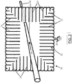
Figure 2 is a schematic view of a current transducer being a second embodiment of the invention; -
Figure 3 is a schematic view of a current transducer being a third embodiment of the invention; and -
Figure 4 is a schematic view of a current transducer being a fourth embodiment of the invention. - Referring first to
Figures 1 and2 , there is shown, generally indicated as 10 and 20 respectively, respective current transducers embodying the invention. Thetransducer conductive coil turns conductive coil charge carrier 5, 28, e.g. a conductor, for carrying current that is desired to be measured. Alternatively the loop may encircle any other current or electrical charge carrier, e.g. a beam, for example, an ion beam. Usually, the arrangement is such that said loop is disposed in a plane which, in use, is substantially perpendicular to thecurrent carrier 5, 28. It is noted however that thecurrent carrier 5, 28 need not necessarily be perpendicular to the plane of the loop and that the loop itself need not necessarily be shaped to lie in a single plane. The turns 14, 24 of the at least onecoil turns - Typically, said turns 14, 24 are electrically connected together in series. This interconnection of turns can be achieved in a variety of ways including, but not limited to, progressive connection of successive turns in a single direction around said loop.
- The turns 14, 24 may be shaped to define any shape, e.g. substantially circular, substantially rectangular or straight-sided with one or more curved corners, especially substantially rectangular with one or more curved corners. Said loop defined by said at least one
coil Figure 3 , or with straight-sided, or 'mitred' corners (e.g. polygonal or quadrilateral),Figure 4 . - Typically, the
turns coil - Typically, but not necessarily, the pitch on straight sections of the
coil - The loop defined by the
coil coil transducer coil 12, 22 (e.g. at the beginning or the end of the at least onecoil 12, 22), but extending around said current carrier 5, 28 (in use) in a direction opposite to the direction of the "net turn" (i.e. such that current is directed in use around said additional length of conductor in an opposite sense to the overall or net current flow around said loop), and preferably being shaped, dimensioned and positioned to define an area that substantially matches the area defined by said loop. Alternatively, the transducer may include a further at least one coil (not shown), in series with thecoil 12,22 (e.g. at the beginning or the end of thecoil 12, 22), and defining a loop that extends around said current carrier 5, 28 (in use) in a direction opposite to the direction of the "net turn" (i.e. such that overall or net current flow around said further at least one coil is in an opposite sense to the overall or net current flow around the loop defined by thecoil 12, 22), and preferably being shaped, dimensioned and positioned to define an area that substantially matches the area defined by said net turn of said loop defined by thecoil - The
transducer terminals coil 12, 22 (and any additional conductors that may be connected to the at least onecoil current carrier 5, 28 can be measured. Typically, said voltage is an aggregate of the respective voltages induced in each turn of thetransducer 10, 20 (including theturns - The
terminals transducer - Referring now in particular to the
transducer 30 ofFigure 3 , the coil may have at least two sections of differing radii, including but not limited to at least one straight section (or a curved section of substantially infinite radius) 31 and at least onecurved corner 32, in which it is consequently not possible to maintain a substantially constant pitch at all radii of the corner. Advantageously,curved corners 32 of the coil are subdivided intonotional bands 33, preferably by the inclusion ofadditional turns 34 of less than full width, such that the ratio of the transverse area of the intersection between a giventurn 34 and the or eachrespective band 33 to its respective notional effective, or average, pitch averaged across the width of the respective band at the intersection is substantially equal to the corresponding area to pitch ratio on astraight section 31 of theband 33. Effective turns' pitch may be calculated as an average pitch (distance) between a turn and an adjacent turn. For example, two adjacent turns at a corner of a coil are non-parallel as a result of the angular pitch between them. Consequently, the pitch between the turns changes, i.e. increases in an outward direction. In this context the pitch is a distance rather than an angle. Where the corner is curved, the pitch may be measured as an arc between the adjacent turns, the curvature of the arc matching the curvature of the corner. Where the corner is straight-edged, the pitch may be measured along straight lines parallel with the corner axes. - The number of
bands 33 in anycurved corner 32 can vary according to the requirements pertaining to the corner. The positions of thenotional boundaries 35 defining the position and width of any of said at least one bands can vary according to the requirements pertaining to the curved corner. - Curved corners of the coil can comprise one or more repeating angular patterns of
turns 36. Within the patterns of turns each band has a given integer number of turns. The greater the radius of theband 33 within thepattern region 36 the greater will be the number of turns in theband 33. There are a variety of possible ratios of turns from one band to an adjacent band of greater radius, including, but not limited to, 1:2, 2:3, 3:4, 4:5, etc. In some embodiments where the turns pass from one band to an adjacent band, the route of the turn may follow the band boundary for a distance which is substantially small relative to the width of the bands, thereby creating aninterconnection 37 between notional subdivisions of the turn. In some embodiments eachinterconnection 37 has, advantageously, a correspondingmirror image interconnection 38 substantially nearby on the same boundary, such that any magnetic field coupling with the oneinterconnection 37 will also couple with theother interconnect 38 in substantially the opposite way, thus substantially cancelling unwanted error signals. - In any embodiment, having a given ratio between the turns' area and turns' pitch (i.e. 'turns' density'), with at least one curved corner linking a first straight section of the coil of a given first width and first turns' pitch giving a ratio substantially equal to the turns' density of the at least one coil, to a second straight section of the coil of a given second width and second turns' pitch giving a ratio substantially equal to the turns' density of the coil, the inner and outer radius of the curved corner, the number and widths of the bands together with the angular pitches of the turns of the bands of the curved corner can be optimised to minimise the deviation of the local effective turns' density at all points of the curved corner from the turns' density, hence minimising the errors due to magnetic fields generated by any external currents and minimising errors due to any dependence on the position of the currents passing through the coil.
- Referring now in particular to the current transducer of
Figure 4 , thecoil 40 has at least twostraight sections 41 meeting in a straight-sided or 'mitred'corner straight line 45 can be drawn from the intersection of the inner edges 46 of the two straight sections to the intersection of the correspondingouter edges 47 of the two straight sections and this notional straight line marks the transition from theturns 48 of one of the two straight sections to theturns 49 of the other straight section of thecoil 40. In embodiments where the width of the two straight sections meeting in the corner are substantially equal 42, 43, it can be seen that the notionaldiagonal line 45 bisects the angle at which the two straight sections meet. - The turns 50 of one of the two straight sections continue into the corner, maintaining substantially the same pitch between adjacent turns, remaining substantially parallel to the
turns 48 of the straight section and substantially uniformly reducing in width as they extend from the continuedouter edge 47 of the straight section to the notionaldiagonal line 45 marking the transition of the corner. In typical embodiments theturns 51 of the other straight section also continue into the corner in substantially the same manner. - The two
straight sections 41 and the straight ormitred corner notional bands 52, the bands filling the transverse area of the sections of the loop defined by thecoil 40, without leaving voids between them and without overlapping each other, the inner andouter edges 53 of the bands being parallel to theedges 46, 47 of thestraight sections 41, thenotional line 53 marking each transition from one of thebands 52 to the adjacent band intersecting the notionaldiagonal line 45 of thecorner intersection 54 of one of the corner turns 50,51 with thediagonal line 45. - The width of the
notional bands 52 is substantially and advantageously of the same order as the pitch of theturns corner intersection straight sections 41 of thecoil 40, such that the change in magnetic field strength, or change in gradient of magnetic field strength, between thecorner intersections 54 of theband 52, resulting from a current flowing substantially near to the said corner of the band, combined with the change in pitch from the inner to the outer edge of the corner intersection of saidband 54, will cause an error which is substantially negligible with respect to the total signal generated by thecoil 40. - In some embodiments the notional
diagonal line 45 marking the transition of the saidcorner 42 marks a line of substantialreflective symmetry 55 between the continuing turns 56 of one straight section and the corresponding turns 57 of the other straight section continuing into the saidcorner 42. - The intersection of two
straight sections 41 of thecoil 40 at a straight-sided ormitred corner 43, having the notionaldiagonal line 45 marking the transition from one straight section to the other straight section, may be configured such that turns 49,51 of one of the two straight sections is shifted along the straight section (offset) by substantially one half turns' pitch, such that theedges 58 of the corner turns of both straight sections lying on the notionaldiagonal line 45 of thecorner 43 lie at substantially equal spacing along the notionaldiagonal line 45 such that the width of thenotional bands 52 into which thecorner 43 is divided is substantially constant. Furthermore, comparing thecorner 43 with thecorner 42, the number of notional bands has been doubled, and their width halved, giving up to a further factor of 4 improvement in the rejection of magnetic fields of external conductors. - The intersection of two straight sections of the
coil 40 at a straight-sided ormitred corner 44, having thenotional line 59 marking the transition from a firststraight section 41 of a first width to the otherstraight section 60 of a second width, may be configured such that the width of the secondstraight section 60 is (substantially) greater than the width of the firststraight section 41, and that thetransition line 59 lies substantially parallel to theturns 61 of the secondstraight section 60 and is substantially perpendicular to the direction of the secondstraight section 60 of thecoil 40, whereas thetransition line 59 crosses the firststraight section 41 at an angle oblique to the said turns 46 of the first straight section. The turns of the secondstraight section 60 continue up to thetransition line 59 substantially uniformly, whereas theturns 50 of the first straight section continue into thecorner 44, maintaining substantially the same pitch between adjacent turns, remaining substantially parallel to theturns 48 of the firststraight section 41 and substantially uniformly reducing in width as they extend from the continuedouter edge 47 of the firststraight section 41 to the notionaldiagonal line 59 marking the said transition of thecorner 44. - It will be understood that the various features described above in relation to any one of the
transducers
Claims (14)
- A current transducer (10, 20, 30) comprising at least one conductive coil (12, 22, 40) shaped to define a plurality of turns (14, 24, 36, 48, 49, 50, 51) and shaped to form a loop, said loop having at least one corner section (32, 42, 43, 44) comprising a plurality of non-parallel turns, characterised in that for each turn there is a substantially constant ratio between respective portions of the area defined by the respective turn and a respective effective turns pitch at a corresponding point of a respective line of integration normal to the respective portion of said turn, wherein said at least one corner section comprises at least one notional band (33, 52) running parallel with a respective notional line (35, 53) around said loop and substantially normal to each of the respective portions of said turns that it intersects, and wherein said turns are shaped and dimensioned such that the ratio of the transverse area of the intersection between a respective turn and said at least one notional band to a respective effective pitch between said turn and an adjacent turn taken as an average across the width of said notional band at said intersection is substantially constant.
- A current transducer as claimed in claim 1, wherein in respect of the, or each, of said at least one notional band (33, 52), the average pitch between successive turns (14, 24, 36, 48, 49, 50, 51) is substantially constant, where said average pitch is an average of the respective pitches between successive adjacent turns across the entire width of the respective notional band.
- A current transducer as claimed in any preceding claim, wherein said at least one corner section (32, 42, 43, 44) includes a first set of turns (48, 49 having a full width and at least one other set of turns (34, 51) having a width less than said full width, and wherein preferably respective sets of turns are interleaved along the length of said at least one corner section.
- A current transducer as claimed in claim 3, wherein the respective width of the turns (14, 24, 36, 48, 49, 50, 51) of one or more of said at least one other set match the respective width of one or more of said at least one notional band (35, 52).
- A current transducer as claimed in any preceding claim, wherein said at least one corner section (32) is curved and located at a respective intersection between substantially straight sections (31), the pitch between successive turns in each of said substantially straight sections and the respective average or effective pitch in said at least one notional band (33) of said at least one corner section being substantially equal.
- A current transducer as claimed in any preceding claim, wherein said loop has at least one angled corner section (42, 43, 44) defined by the intersection of first and second straight sections (41), said angled corner section comprising a respective set of turns (48, 49, 50, 51) extending between a respective one of said substantially straight sections and the apex of the corner section, wherein the respective turns of each set are substantially parallel with one another, and the respective width of successive adjacent turns of each set decreases in a direction from said respective straight section towards said apex, and wherein preferably each set comprises the same number of turns.
- A current transducer as claimed in claim 6, wherein the pitch between adjacent turns (48, 49, 50, 51) of each set is substantially constant, and preferably substantially the same as the respective pitch between adjacent turns of the other set.
- A current transducer as claimed in any one of claims 5 to 7, wherein said sets are offset with respect to one another about a notional axis that bisects said corner section and extends radially of said loop, said offset preferably being substantially equal to 50% of the pitch between adjacent turns (48, 49, 50, 51) of said sets.
- A current transducer as claimed in claim 5, wherein said at least one curved corner section (32) comprises at least two notional bands (33) running parallel with a notional line (35) around said loop and substantially normal to each of the respective turns that it intersects, said notional bands being mutually spaced-apart in a direction substantially perpendicular with said notional line, each notional band comprising a respective set of non-parallel turns (36), each set extending at least partly but preferably fully around said at least one corner section, and wherein preferably the angular pitch between adjacent turns of each set is substantially constant.
- A current transducer as claimed in claim 9, wherein for each notional band (33), the effective average pitch between successive turns (36) is substantially constant, where said effective average pitch is an average of the respective pitches between adjacent turns across the entire width of the respective notional band.
- A current transducer as claimed in claim 9 or 10, wherein the width of at least some of the turns (36) in said at least one curved corner section (32) is smaller than the width of the turns in one or more adjacent straight sections (31).
- A current transducer as claimed in any one of claims 9 to 11, wherein one or more respective turns (36) of two or more notional bands (33) are substantially aligned, said substantially aligned turns being implemented as a single turn extending across said two or more notional bands.
- A current transducer as claimed in any one of claims 9 to 12, wherein respective ends of respective turns (36) from respective notional bands (33) that are located adjacent a boundary between said respective notional bands are electrically connected together.
- A current transducer as claimed in any preceding claim, wherein the effective turn's density is substantially constant along said at least one coil (12, 22, 40), preferably around said loop.
Applications Claiming Priority (2)
| Application Number | Priority Date | Filing Date | Title |
|---|---|---|---|
| GBGB1116091.8A GB201116091D0 (en) | 2011-09-16 | 2011-09-16 | Precision near-field current transducer |
| PCT/EP2012/068180 WO2013037986A1 (en) | 2011-09-16 | 2012-09-16 | Precision near-field current transducer |
Publications (2)
| Publication Number | Publication Date |
|---|---|
| EP2756319A1 EP2756319A1 (en) | 2014-07-23 |
| EP2756319B1 true EP2756319B1 (en) | 2019-08-07 |
Family
ID=44937443
Family Applications (1)
| Application Number | Title | Priority Date | Filing Date |
|---|---|---|---|
| EP12773245.1A Active EP2756319B1 (en) | 2011-09-16 | 2012-09-16 | Precision near-field current transducer |
Country Status (3)
| Country | Link |
|---|---|
| EP (1) | EP2756319B1 (en) |
| GB (1) | GB201116091D0 (en) |
| WO (1) | WO2013037986A1 (en) |
Families Citing this family (3)
| Publication number | Priority date | Publication date | Assignee | Title |
|---|---|---|---|---|
| FR3033647B1 (en) | 2015-03-10 | 2019-07-26 | Socomec | CURRENT SENSOR FOR MEASURING ALTERNATING CURRENT |
| FR3044096B1 (en) | 2015-11-23 | 2017-12-01 | Schneider Electric Ind Sas | CURRENT SENSOR AND DEVICE FOR MEASURING AN ELECTRICAL CURRENT |
| FR3097053B1 (en) * | 2019-06-07 | 2021-07-02 | Schneider Electric Ind Sas | Current sensors and associated measuring systems |
Family Cites Families (10)
| Publication number | Priority date | Publication date | Assignee | Title |
|---|---|---|---|---|
| US3626291A (en) * | 1969-05-12 | 1971-12-07 | Halmar Electronics | Current-measuring apparatus |
| FR2559268B1 (en) * | 1984-02-06 | 1986-05-09 | Centre Nat Rech Scient | DEVICE FOR MEASURING AN ELECTRIC CURRENT USING A REGULAR TORO-SHAPED SOLENOID |
| US4897600A (en) * | 1987-11-13 | 1990-01-30 | Florida International University | High frequency ammeter |
| DE4424368A1 (en) * | 1994-07-11 | 1995-07-06 | Siemens Ag | Producing Rogowski coil for current measurement unit |
| JP4129932B2 (en) * | 1998-04-09 | 2008-08-06 | 日置電機株式会社 | Current sensor structure for clamp sensor |
| EP1183543B1 (en) * | 1999-05-25 | 2003-04-23 | Arbeitsgemeinschaft Prof. Hugel AGPH | Electrical current sensor |
| US6313623B1 (en) * | 2000-02-03 | 2001-11-06 | Mcgraw-Edison Company | High precision rogowski coil |
| FR2870350B1 (en) * | 2004-05-13 | 2006-07-14 | Schneider Electric Ind Sas | DEVICE FOR MEASURING AN ELECTRICAL CURRENT, CURRENT SENSOR, ELECTRICAL SENSOR AND CUTTING DEVICE COMPRISING SUCH A MEASURING DEVICE |
| GB0412129D0 (en) * | 2004-05-29 | 2004-06-30 | Lem Heme Ltd | Improvements in and relating to current measuring apparatus |
| JP4648241B2 (en) * | 2006-05-17 | 2011-03-09 | 日置電機株式会社 | Magnetic sensor and current measuring device |
-
2011
- 2011-09-16 GB GBGB1116091.8A patent/GB201116091D0/en not_active Ceased
-
2012
- 2012-09-16 EP EP12773245.1A patent/EP2756319B1/en active Active
- 2012-09-16 WO PCT/EP2012/068180 patent/WO2013037986A1/en not_active Ceased
Non-Patent Citations (1)
| Title |
|---|
| None * |
Also Published As
| Publication number | Publication date |
|---|---|
| WO2013037986A1 (en) | 2013-03-21 |
| GB201116091D0 (en) | 2011-11-02 |
| EP2756319A1 (en) | 2014-07-23 |
Similar Documents
| Publication | Publication Date | Title |
|---|---|---|
| EP1264188B1 (en) | High precision rogowski coil | |
| CN110323049B (en) | Coil component and wireless power transmission circuit having the same | |
| CN100472174C (en) | Magnetoresistive sensors for determining angle or position | |
| US9891293B2 (en) | Magnetic sensor device preventing concentration of magnetic fluxes to a magnetic sensing element | |
| US20200088549A1 (en) | Coupler element shapes for inductive position sensors | |
| US5012218A (en) | Device for measuring an electric current using a solenoid with regular pitch in the form of a torus | |
| US10877075B2 (en) | Current sensor | |
| US5680046A (en) | Double-sided RF shield for RF coil contained within gradient coils used in high speed NMR imaging | |
| CN102822634A (en) | Inductive position sensor | |
| GB2469906A (en) | Shielded Gradient Coil | |
| KR20150002731A (en) | Three-phase choke | |
| EP4542177A1 (en) | Inductive position detector | |
| US4050303A (en) | Fluid flow meters | |
| JP7593763B2 (en) | Current Detector | |
| WO2013037986A1 (en) | Precision near-field current transducer | |
| JP6547572B2 (en) | Power supply device | |
| JPH06213678A (en) | Pickup for inducing and generating measured signal | |
| CN116568996A (en) | Rotary transformer | |
| JP2015512569A (en) | Three-phase two-phase fixed transformer with forcibly coupled magnetic flux | |
| JP2638460B2 (en) | Induct thin sensor | |
| JP2012198053A (en) | Magnetic sensor and current sensor using the same | |
| JPH03218414A (en) | Electromagnetic flowmeter | |
| US20240329092A1 (en) | Current Sensing Device | |
| US11901780B2 (en) | Resolver | |
| Dixon | Magnetic field evaluation in transformers and inductors |
Legal Events
| Date | Code | Title | Description |
|---|---|---|---|
| PUAI | Public reference made under article 153(3) epc to a published international application that has entered the european phase |
Free format text: ORIGINAL CODE: 0009012 |
|
| 17P | Request for examination filed |
Effective date: 20140416 |
|
| AK | Designated contracting states |
Kind code of ref document: A1 Designated state(s): AL AT BE BG CH CY CZ DE DK EE ES FI FR GB GR HR HU IE IS IT LI LT LU LV MC MK MT NL NO PL PT RO RS SE SI SK SM TR |
|
| DAX | Request for extension of the european patent (deleted) | ||
| STAA | Information on the status of an ep patent application or granted ep patent |
Free format text: STATUS: EXAMINATION IS IN PROGRESS |
|
| 17Q | First examination report despatched |
Effective date: 20170419 |
|
| GRAP | Despatch of communication of intention to grant a patent |
Free format text: ORIGINAL CODE: EPIDOSNIGR1 |
|
| STAA | Information on the status of an ep patent application or granted ep patent |
Free format text: STATUS: GRANT OF PATENT IS INTENDED |
|
| INTG | Intention to grant announced |
Effective date: 20180815 |
|
| GRAS | Grant fee paid |
Free format text: ORIGINAL CODE: EPIDOSNIGR3 |
|
| GRAJ | Information related to disapproval of communication of intention to grant by the applicant or resumption of examination proceedings by the epo deleted |
Free format text: ORIGINAL CODE: EPIDOSDIGR1 |
|
| GRAL | Information related to payment of fee for publishing/printing deleted |
Free format text: ORIGINAL CODE: EPIDOSDIGR3 |
|
| STAA | Information on the status of an ep patent application or granted ep patent |
Free format text: STATUS: EXAMINATION IS IN PROGRESS |
|
| INTC | Intention to grant announced (deleted) | ||
| GRAP | Despatch of communication of intention to grant a patent |
Free format text: ORIGINAL CODE: EPIDOSNIGR1 |
|
| STAA | Information on the status of an ep patent application or granted ep patent |
Free format text: STATUS: GRANT OF PATENT IS INTENDED |
|
| INTG | Intention to grant announced |
Effective date: 20190304 |
|
| GRAA | (expected) grant |
Free format text: ORIGINAL CODE: 0009210 |
|
| STAA | Information on the status of an ep patent application or granted ep patent |
Free format text: STATUS: THE PATENT HAS BEEN GRANTED |
|
| AK | Designated contracting states |
Kind code of ref document: B1 Designated state(s): AL AT BE BG CH CY CZ DE DK EE ES FI FR GB GR HR HU IE IS IT LI LT LU LV MC MK MT NL NO PL PT RO RS SE SI SK SM TR |
|
| REG | Reference to a national code |
Ref country code: GB Ref legal event code: FG4D |
|
| REG | Reference to a national code |
Ref country code: CH Ref legal event code: EP Ref country code: AT Ref legal event code: REF Ref document number: 1164667 Country of ref document: AT Kind code of ref document: T Effective date: 20190815 |
|
| REG | Reference to a national code |
Ref country code: DE Ref legal event code: R096 Ref document number: 602012062713 Country of ref document: DE |
|
| REG | Reference to a national code |
Ref country code: IE Ref legal event code: FG4D |
|
| REG | Reference to a national code |
Ref country code: NL Ref legal event code: MP Effective date: 20190807 |
|
| REG | Reference to a national code |
Ref country code: LT Ref legal event code: MG4D |
|
| PG25 | Lapsed in a contracting state [announced via postgrant information from national office to epo] |
Ref country code: FI Free format text: LAPSE BECAUSE OF FAILURE TO SUBMIT A TRANSLATION OF THE DESCRIPTION OR TO PAY THE FEE WITHIN THE PRESCRIBED TIME-LIMIT Effective date: 20190807 Ref country code: LT Free format text: LAPSE BECAUSE OF FAILURE TO SUBMIT A TRANSLATION OF THE DESCRIPTION OR TO PAY THE FEE WITHIN THE PRESCRIBED TIME-LIMIT Effective date: 20190807 Ref country code: HR Free format text: LAPSE BECAUSE OF FAILURE TO SUBMIT A TRANSLATION OF THE DESCRIPTION OR TO PAY THE FEE WITHIN THE PRESCRIBED TIME-LIMIT Effective date: 20190807 Ref country code: PT Free format text: LAPSE BECAUSE OF FAILURE TO SUBMIT A TRANSLATION OF THE DESCRIPTION OR TO PAY THE FEE WITHIN THE PRESCRIBED TIME-LIMIT Effective date: 20191209 Ref country code: SE Free format text: LAPSE BECAUSE OF FAILURE TO SUBMIT A TRANSLATION OF THE DESCRIPTION OR TO PAY THE FEE WITHIN THE PRESCRIBED TIME-LIMIT Effective date: 20190807 Ref country code: NL Free format text: LAPSE BECAUSE OF FAILURE TO SUBMIT A TRANSLATION OF THE DESCRIPTION OR TO PAY THE FEE WITHIN THE PRESCRIBED TIME-LIMIT Effective date: 20190807 Ref country code: BG Free format text: LAPSE BECAUSE OF FAILURE TO SUBMIT A TRANSLATION OF THE DESCRIPTION OR TO PAY THE FEE WITHIN THE PRESCRIBED TIME-LIMIT Effective date: 20191107 Ref country code: NO Free format text: LAPSE BECAUSE OF FAILURE TO SUBMIT A TRANSLATION OF THE DESCRIPTION OR TO PAY THE FEE WITHIN THE PRESCRIBED TIME-LIMIT Effective date: 20191107 |
|
| REG | Reference to a national code |
Ref country code: AT Ref legal event code: MK05 Ref document number: 1164667 Country of ref document: AT Kind code of ref document: T Effective date: 20190807 |
|
| PG25 | Lapsed in a contracting state [announced via postgrant information from national office to epo] |
Ref country code: ES Free format text: LAPSE BECAUSE OF FAILURE TO SUBMIT A TRANSLATION OF THE DESCRIPTION OR TO PAY THE FEE WITHIN THE PRESCRIBED TIME-LIMIT Effective date: 20190807 Ref country code: GR Free format text: LAPSE BECAUSE OF FAILURE TO SUBMIT A TRANSLATION OF THE DESCRIPTION OR TO PAY THE FEE WITHIN THE PRESCRIBED TIME-LIMIT Effective date: 20191108 Ref country code: LV Free format text: LAPSE BECAUSE OF FAILURE TO SUBMIT A TRANSLATION OF THE DESCRIPTION OR TO PAY THE FEE WITHIN THE PRESCRIBED TIME-LIMIT Effective date: 20190807 Ref country code: IS Free format text: LAPSE BECAUSE OF FAILURE TO SUBMIT A TRANSLATION OF THE DESCRIPTION OR TO PAY THE FEE WITHIN THE PRESCRIBED TIME-LIMIT Effective date: 20191207 Ref country code: RS Free format text: LAPSE BECAUSE OF FAILURE TO SUBMIT A TRANSLATION OF THE DESCRIPTION OR TO PAY THE FEE WITHIN THE PRESCRIBED TIME-LIMIT Effective date: 20190807 Ref country code: AL Free format text: LAPSE BECAUSE OF FAILURE TO SUBMIT A TRANSLATION OF THE DESCRIPTION OR TO PAY THE FEE WITHIN THE PRESCRIBED TIME-LIMIT Effective date: 20190807 |
|
| PG25 | Lapsed in a contracting state [announced via postgrant information from national office to epo] |
Ref country code: TR Free format text: LAPSE BECAUSE OF FAILURE TO SUBMIT A TRANSLATION OF THE DESCRIPTION OR TO PAY THE FEE WITHIN THE PRESCRIBED TIME-LIMIT Effective date: 20190807 |
|
| PG25 | Lapsed in a contracting state [announced via postgrant information from national office to epo] |
Ref country code: PL Free format text: LAPSE BECAUSE OF FAILURE TO SUBMIT A TRANSLATION OF THE DESCRIPTION OR TO PAY THE FEE WITHIN THE PRESCRIBED TIME-LIMIT Effective date: 20190807 Ref country code: AT Free format text: LAPSE BECAUSE OF FAILURE TO SUBMIT A TRANSLATION OF THE DESCRIPTION OR TO PAY THE FEE WITHIN THE PRESCRIBED TIME-LIMIT Effective date: 20190807 Ref country code: EE Free format text: LAPSE BECAUSE OF FAILURE TO SUBMIT A TRANSLATION OF THE DESCRIPTION OR TO PAY THE FEE WITHIN THE PRESCRIBED TIME-LIMIT Effective date: 20190807 Ref country code: RO Free format text: LAPSE BECAUSE OF FAILURE TO SUBMIT A TRANSLATION OF THE DESCRIPTION OR TO PAY THE FEE WITHIN THE PRESCRIBED TIME-LIMIT Effective date: 20190807 Ref country code: DK Free format text: LAPSE BECAUSE OF FAILURE TO SUBMIT A TRANSLATION OF THE DESCRIPTION OR TO PAY THE FEE WITHIN THE PRESCRIBED TIME-LIMIT Effective date: 20190807 |
|
| PG25 | Lapsed in a contracting state [announced via postgrant information from national office to epo] |
Ref country code: SK Free format text: LAPSE BECAUSE OF FAILURE TO SUBMIT A TRANSLATION OF THE DESCRIPTION OR TO PAY THE FEE WITHIN THE PRESCRIBED TIME-LIMIT Effective date: 20190807 Ref country code: SM Free format text: LAPSE BECAUSE OF FAILURE TO SUBMIT A TRANSLATION OF THE DESCRIPTION OR TO PAY THE FEE WITHIN THE PRESCRIBED TIME-LIMIT Effective date: 20190807 Ref country code: MC Free format text: LAPSE BECAUSE OF FAILURE TO SUBMIT A TRANSLATION OF THE DESCRIPTION OR TO PAY THE FEE WITHIN THE PRESCRIBED TIME-LIMIT Effective date: 20190807 Ref country code: IS Free format text: LAPSE BECAUSE OF FAILURE TO SUBMIT A TRANSLATION OF THE DESCRIPTION OR TO PAY THE FEE WITHIN THE PRESCRIBED TIME-LIMIT Effective date: 20200224 Ref country code: CZ Free format text: LAPSE BECAUSE OF FAILURE TO SUBMIT A TRANSLATION OF THE DESCRIPTION OR TO PAY THE FEE WITHIN THE PRESCRIBED TIME-LIMIT Effective date: 20190807 |
|
| REG | Reference to a national code |
Ref country code: CH Ref legal event code: PL |
|
| REG | Reference to a national code |
Ref country code: DE Ref legal event code: R097 Ref document number: 602012062713 Country of ref document: DE |
|
| PLBE | No opposition filed within time limit |
Free format text: ORIGINAL CODE: 0009261 |
|
| STAA | Information on the status of an ep patent application or granted ep patent |
Free format text: STATUS: NO OPPOSITION FILED WITHIN TIME LIMIT |
|
| PG2D | Information on lapse in contracting state deleted |
Ref country code: IS |
|
| PG25 | Lapsed in a contracting state [announced via postgrant information from national office to epo] |
Ref country code: LU Free format text: LAPSE BECAUSE OF NON-PAYMENT OF DUE FEES Effective date: 20190916 Ref country code: IE Free format text: LAPSE BECAUSE OF NON-PAYMENT OF DUE FEES Effective date: 20190916 Ref country code: CH Free format text: LAPSE BECAUSE OF NON-PAYMENT OF DUE FEES Effective date: 20190930 Ref country code: LI Free format text: LAPSE BECAUSE OF NON-PAYMENT OF DUE FEES Effective date: 20190930 |
|
| REG | Reference to a national code |
Ref country code: BE Ref legal event code: MM Effective date: 20190930 |
|
| 26N | No opposition filed |
Effective date: 20200603 |
|
| PG25 | Lapsed in a contracting state [announced via postgrant information from national office to epo] |
Ref country code: BE Free format text: LAPSE BECAUSE OF NON-PAYMENT OF DUE FEES Effective date: 20190930 Ref country code: SI Free format text: LAPSE BECAUSE OF FAILURE TO SUBMIT A TRANSLATION OF THE DESCRIPTION OR TO PAY THE FEE WITHIN THE PRESCRIBED TIME-LIMIT Effective date: 20190807 |
|
| PG25 | Lapsed in a contracting state [announced via postgrant information from national office to epo] |
Ref country code: CY Free format text: LAPSE BECAUSE OF FAILURE TO SUBMIT A TRANSLATION OF THE DESCRIPTION OR TO PAY THE FEE WITHIN THE PRESCRIBED TIME-LIMIT Effective date: 20190807 |
|
| PG25 | Lapsed in a contracting state [announced via postgrant information from national office to epo] |
Ref country code: MT Free format text: LAPSE BECAUSE OF FAILURE TO SUBMIT A TRANSLATION OF THE DESCRIPTION OR TO PAY THE FEE WITHIN THE PRESCRIBED TIME-LIMIT Effective date: 20190807 Ref country code: HU Free format text: LAPSE BECAUSE OF FAILURE TO SUBMIT A TRANSLATION OF THE DESCRIPTION OR TO PAY THE FEE WITHIN THE PRESCRIBED TIME-LIMIT; INVALID AB INITIO Effective date: 20120916 |
|
| PG25 | Lapsed in a contracting state [announced via postgrant information from national office to epo] |
Ref country code: MK Free format text: LAPSE BECAUSE OF FAILURE TO SUBMIT A TRANSLATION OF THE DESCRIPTION OR TO PAY THE FEE WITHIN THE PRESCRIBED TIME-LIMIT Effective date: 20190807 |
|
| P01 | Opt-out of the competence of the unified patent court (upc) registered |
Effective date: 20230525 |
|
| PGFP | Annual fee paid to national office [announced via postgrant information from national office to epo] |
Ref country code: IT Payment date: 20250929 Year of fee payment: 14 |
|
| PGFP | Annual fee paid to national office [announced via postgrant information from national office to epo] |
Ref country code: GB Payment date: 20250922 Year of fee payment: 14 |
|
| PGFP | Annual fee paid to national office [announced via postgrant information from national office to epo] |
Ref country code: FR Payment date: 20250929 Year of fee payment: 14 |
|
| PGFP | Annual fee paid to national office [announced via postgrant information from national office to epo] |
Ref country code: DE Payment date: 20250929 Year of fee payment: 14 |