EP2755280A1 - Crimp contact and cable assembly including the same - Google Patents
Crimp contact and cable assembly including the same Download PDFInfo
- Publication number
- EP2755280A1 EP2755280A1 EP14150486.0A EP14150486A EP2755280A1 EP 2755280 A1 EP2755280 A1 EP 2755280A1 EP 14150486 A EP14150486 A EP 14150486A EP 2755280 A1 EP2755280 A1 EP 2755280A1
- Authority
- EP
- European Patent Office
- Prior art keywords
- sidewall
- section
- crimp contact
- base section
- contact
- Prior art date
- Legal status (The legal status is an assumption and is not a legal conclusion. Google has not performed a legal analysis and makes no representation as to the accuracy of the status listed.)
- Granted
Links
Images




Classifications
-
- H—ELECTRICITY
- H01—ELECTRIC ELEMENTS
- H01R—ELECTRICALLY-CONDUCTIVE CONNECTIONS; STRUCTURAL ASSOCIATIONS OF A PLURALITY OF MUTUALLY-INSULATED ELECTRICAL CONNECTING ELEMENTS; COUPLING DEVICES; CURRENT COLLECTORS
- H01R4/00—Electrically-conductive connections between two or more conductive members in direct contact, i.e. touching one another; Means for effecting or maintaining such contact; Electrically-conductive connections having two or more spaced connecting locations for conductors and using contact members penetrating insulation
- H01R4/10—Electrically-conductive connections between two or more conductive members in direct contact, i.e. touching one another; Means for effecting or maintaining such contact; Electrically-conductive connections having two or more spaced connecting locations for conductors and using contact members penetrating insulation effected solely by twisting, wrapping, bending, crimping, or other permanent deformation
- H01R4/18—Electrically-conductive connections between two or more conductive members in direct contact, i.e. touching one another; Means for effecting or maintaining such contact; Electrically-conductive connections having two or more spaced connecting locations for conductors and using contact members penetrating insulation effected solely by twisting, wrapping, bending, crimping, or other permanent deformation by crimping
-
- H—ELECTRICITY
- H01—ELECTRIC ELEMENTS
- H01R—ELECTRICALLY-CONDUCTIVE CONNECTIONS; STRUCTURAL ASSOCIATIONS OF A PLURALITY OF MUTUALLY-INSULATED ELECTRICAL CONNECTING ELEMENTS; COUPLING DEVICES; CURRENT COLLECTORS
- H01R4/00—Electrically-conductive connections between two or more conductive members in direct contact, i.e. touching one another; Means for effecting or maintaining such contact; Electrically-conductive connections having two or more spaced connecting locations for conductors and using contact members penetrating insulation
- H01R4/10—Electrically-conductive connections between two or more conductive members in direct contact, i.e. touching one another; Means for effecting or maintaining such contact; Electrically-conductive connections having two or more spaced connecting locations for conductors and using contact members penetrating insulation effected solely by twisting, wrapping, bending, crimping, or other permanent deformation
- H01R4/18—Electrically-conductive connections between two or more conductive members in direct contact, i.e. touching one another; Means for effecting or maintaining such contact; Electrically-conductive connections having two or more spaced connecting locations for conductors and using contact members penetrating insulation effected solely by twisting, wrapping, bending, crimping, or other permanent deformation by crimping
- H01R4/183—Electrically-conductive connections between two or more conductive members in direct contact, i.e. touching one another; Means for effecting or maintaining such contact; Electrically-conductive connections having two or more spaced connecting locations for conductors and using contact members penetrating insulation effected solely by twisting, wrapping, bending, crimping, or other permanent deformation by crimping for cylindrical elongated bodies, e.g. cables having circular cross-section
-
- H—ELECTRICITY
- H01—ELECTRIC ELEMENTS
- H01R—ELECTRICALLY-CONDUCTIVE CONNECTIONS; STRUCTURAL ASSOCIATIONS OF A PLURALITY OF MUTUALLY-INSULATED ELECTRICAL CONNECTING ELEMENTS; COUPLING DEVICES; CURRENT COLLECTORS
- H01R43/00—Apparatus or processes specially adapted for manufacturing, assembling, maintaining, or repairing of line connectors or current collectors or for joining electric conductors
- H01R43/04—Apparatus or processes specially adapted for manufacturing, assembling, maintaining, or repairing of line connectors or current collectors or for joining electric conductors for forming connections by deformation, e.g. crimping tool
- H01R43/058—Crimping mandrels
Definitions
- the subject matter described and/or illustrated herein relates generally to crimp contacts that are deformed to grip one or more exposed wire conductors of an electrical wire.
- a crimp contact is a type of electrical contact that is deformed (i.e., crimped) to grip wire conductors that are exposed at a terminating end of an electrical wire.
- the wire conductors are inserted into a cavity defined by the crimp contact, and the crimp contact is then deformed (e.g., crushed) so that the interior surfaces of the crimp contact compress and securely engage the wire conductors.
- Crimp contacts may facilitate connecting the electrical wire to other electrical connectors or devices.
- Crimp contacts may also be used to join terminating ends from two electrical wires in which the wire conductors from each terminating end are inserted into the cavity of the crimp contact prior to deforming.
- crimp contacts are sized according to a total cross-sectional area of the wire conductors that the crimp contacts will engage.
- these known crimp contacts are typically only suitable for a limited number of cross-sectional areas.
- one contact configuration may only be suitable for the wire conductors of electrical wires that have wire gauges 18-20 American Wire Gauge (AWG) (1.024 - 0.812 mm diameter).
- AWG is a frequently used standard in the industry.
- the tools used to deform the crimp contacts are typically configured for one type of crimp contact. As such, a manufacturer or individual working with electrical wires of different wire gauges may require a number of different crimp contacts and a number of different crimping tools.
- a cable assembly in one embodiment, includes an electrical wire having a terminal end that includes at least one exposed wire conductor.
- the cable assembly also includes a crimp contact having a centerline and first and second sidewalls that extend from the centerline in opposite directions.
- the centerline extends parallel to a longitudinal axis of the crimp contact.
- Each of the first and second sidewalls has a base section and a leg section.
- the leg section extends a lateral distance from the centerline to a longitudinal edge of the leg section.
- the base section extends a lateral distance from the centerline to a longitudinal edge of the base section.
- the lateral distance of the leg section is greater than the lateral distance of the base section for each of the first and second sidewalls.
- the leg section of the first sidewall is located opposite the base section of the second sidewall.
- the leg section of the second sidewall is located opposite the base section of the first sidewall.
- the first and second sidewalls surround and engage the at least one wire conductor.
- a crimp contact in another embodiment, includes a contact body having a centerline and first and second sidewalls that extend from the centerline in opposite directions away.
- the centerline extends parallel to a longitudinal axis of the crimp contact.
- Each of the first and second sidewalls has a base section and a leg section.
- the leg section extends a lateral distance from the centerline to a longitudinal edge of the leg section.
- the base section extends a lateral distance from the centerline to a longitudinal edge of the base section.
- the lateral distance of the leg section is greater than the lateral distance of the base section for each of the first and second sidewalls.
- the leg section of the first sidewall is located opposite the base section of the second sidewall.
- the leg section of the second sidewall is located opposite the base section of the first sidewall.
- the leg section of the first sidewall interfaces with the base section of the second sidewall and/or the leg section of the second sidewall interfaces with the base section of the first sidewall.
- the leg section of one of the sidewalls may be folded under the base section of the opposite sidewall.
- the longitudinal edge of the leg section of one of the sidewalls may interface with the longitudinal edge of the base section of the opposite sidewall.
- the crimp contact is dimensioned to surround and engage at least one wire conductor that has a total cross-sectional area of X and, separately, to surround and engage at least one wire conductor that has a total cross-sectional area of at least about 3X.
- each of the leg sections of the first and second sidewalls surrounds a plurality of the wire conductors. Furthermore, in some embodiments, each of the leg sections of the first and second sidewalls may surround a different arrangement of the wire conductors.
- the wire conductors may also have a varying conductor density or distribution within the crimp contact as the crimp contact extends from a leading edge of the crimp contact to the electrical wire. For example, the wire conductors may laterally shift within a contact cavity of the crimp contact.
- each of the leg sections of the first and second sidewalls may surround at least one common wire conductor (e.g., the same wire conductor).
- FIG. 1 is a perspective view of a portion of a cable assembly 100 in accordance with one embodiment before a crimping operation (referenced as 102) and after the crimping operation (referenced as 104).
- the cable assembly 100 includes a crimp contact 105 and an electrical wire 106 having a terminal end 108 that includes at least one exposed wire conductor 110.
- the electrical wire 106 may be used to transmit electrical power or data signals.
- the electrical wire 106 may have a jacket 107 that is removed (e.g., stripped) to expose the wire conductors 110.
- the electrical wire 106 includes sixteen wire conductors (or strands) 110, but the electrical wire 106 may have fewer or more wire conductors 110 in other embodiments.
- the cable assembly 100 is oriented with respect to a central longitudinal axis 190.
- the longitudinal axis 190 may extend through a geometric center of the cable assembly 100 after formation.
- the crimp contact 105 is configured to be deformed (e.g., crimped or crushed) during the crimping operation to grip the wire conductors 110 and thereby establish an electrical and mechanical connection between the wire conductors 110 and the crimp contact 105.
- the crimp contact 105 only grips the wire conductors 110 of one electrical wire 106.
- the wire conductors from separate electrical wires may be inserted into a channel of the crimp contact 105 and pressed together (e.g., mechanically and electrically joined) within the channel through the crimping operation.
- the crimp contact 105 may be stamped and formed from conductive sheet material (e.g., metal). As described herein, the crimp contact 105 may be dimensioned to grip a plurality of different wire gauges within a designated range. For example, the crimp contact 105 may be dimensioned to grip cables or electrical wires having an American Wire Gauge (AWG) between 10-22 AWG (2.588 - 0.644 mm diameter). In particular embodiments, the crimp contact 105 may be dimensioned to surround and grip wire conductors having a total cross-sectional area of X and, separately, to surround and grip wire conductors having a total cross-sectional area of at least about 3X or 5X or, more particularly, at least about 8X.
- AMG American Wire Gauge
- a first type of electrical wire may have wire conductors with a total (e.g., collective) cross-sectional area of about 0.75 mm 2 and a second type of electrical wire may have wire conductors with a total cross-sectional area of at least about 5.00 mm 2 .
- Embodiments described herein may be configured to grip either of the first and second types.
- a first type of electrical wire may have wire conductors with a total cross-sectional area of about 1.00 mm 2 and a second type of electrical wire may have wire conductors with a total cross-sectional area of at least about 3.00 mm 2 .
- each strand may have, by way of example only, radiuses of about 0.125 mm.
- the wire conductors may have other dimensions in alternative embodiments.
- Figure 2 is a plan view of the crimp contact 105 after the crimp contact 105 is stamped from sheet material but before being shaped for the crimping operation.
- the crimp contact 105 has a contact body 114 that extends longitudinally between a leading edge or end 116 and a trailing edge or end 118.
- the contact body 114 has a contact length 130 that is measured along the longitudinal axis 190 ( Figure 1 ).
- the contact body 114 has an interior surface 150 and an exterior surface 152 that face in opposite directions and define a thickness 154 ( Figure 1 ) of the contact body 114 therebetween.
- the thickness 154 is substantially uniform throughout, but may vary in other embodiments.
- the interior surface 150 is configured to directly engage the wire conductors 110. In some embodiments, a portion of the exterior surface 152 may also engage the wire conductors 110 after the crimping operation.
- the contact body 114 includes a center portion 122 and opposite first and second sidewalls 124, 126, that are joined by the center portion 122. As shown in Figure 2 , the contact body 114 has a centerline 160 that extends through a middle of the center portion 122. The center portion 122 and the centerline 160 may extend parallel to the longitudinal axis 190 ( Figure 1 ). As shown in Figures 1 and 2 , the first and second sidewalls 124, 126 extend in opposite directions away from the center portion 122 (or the centerline 160). As such, the first and second sidewalls 124, 126 may be characterized as extending laterally away from the center portion 122 (or the centerline 160).
- the first and second sidewalls 124, 126 are configured to be deformed around and pressed against the wire conductors 110.
- the first and second sidewalls 124, 126 may have similar structural features.
- the first sidewall 124 has a base section 132 and a leg section 134
- the second sidewall 126 may also have a base section 142 and a leg section 144.
- the base and leg sections 132, 134 have longitudinal edges 162, 164, respectively, and the base and leg sections 142, 144 have longitudinal edges 172, 174.
- the longitudinal edges 162, 164, 172, 174 extend parallel to the longitudinal axis 190 in the illustrated embodiment.
- the leg section 134 and the base section 142 are located along the leading edge 116, and the leg section 144 and the base section 132 are located along the trailing edge 118.
- the leg section 134 is defined between a portion of the leading edge 116 and an interior edge 180.
- the leading and interior edges 116, 180 may face in opposite directions along the longitudinal axis 190.
- the interior edge 180 extends between the longitudinal edges 162, 164.
- the leg section 144 is defined between a portion of the trailing edge 118 and an interior edge 182.
- the leading and interior edges 118, 182 may face in opposite directions along the longitudinal axis 190.
- the interior edge 182 extends between the longitudinal edges 172, 174.
- the interior edges 180, 182 extend in directions that are substantially transverse (or perpendicular) to the longitudinal axis 190.
- the interior edges 180, 182 may also be characterized as extending along planes that are substantially orthogonal to the longitudinal axis 190.
- the leg section 134 and the base section 142 may be located opposite each other, and the leg section 144 and the base section 132 may be located opposite each other.
- the sections of the different sidewalls extend different lateral distances from the center portion 122 or the centerline 160.
- the leg section 134 extends a lateral distance 135 from the centerline 160 to the longitudinal edge 164 of the leg section 134.
- the base section 132 extends a lateral distance 133 from the centerline 160 to the longitudinal edge 162 of the base section 132.
- the lateral distance 135 of the leg section 134 is greater than the lateral distance 133 of the base section 132.
- the leg section 144 extends a lateral distance 145 from the centerline 160 to the longitudinal edge 174 of the leg section 144.
- the base section 142 extends a lateral distance 143 from the centerline 160 to the longitudinal edge 172 of the base section 142. Accordingly, the contact body 114 may have a staggered geometric configuration in which each of the longer leg sections directly opposes a shorter base section.
- the lateral distances 135 and 145 are substantially equal and the lateral distances 133 and 143 are substantially equal. In other embodiments, however, the lateral distances 135, 145 may not be equal and/or the lateral distances 133, 143 may not be equal.
- the contact body 114 includes only two leg sections and only two base sections. In other embodiments, there may be more leg sections and/or base sections. For example, a third leg section may extend along the trailing edge 118 such that the base section 132 is located between the third leg section and the leg section 134. A third base section may extend along the trailing edge 118 such that the leg section 144 is located between the third base section and the base section 142.
- the contact body is not required to have opposing leg and base sections throughout. For example, in another alternative embodiment, third and fourth base sections may oppose each other along the trailing edge 118 with the centerline 160 therebetween.
- the longitudinal edges 162, 164, 172, 174 may define a section width 186.
- the section width 186 is measured along the longitudinal axis 190.
- Each of the longitudinal edges 162, 164, 172, 174 may have a substantially equal section width 186 as shown in Figure 2 .
- the section widths 186 may not be equal.
- the cable assembly 100 may be mechanically and electrically connected to a mating contact 112 during a mating operation.
- the mating contact 112 may have a projection 121 that is configured to engage an electrical connector.
- the mating contact 112 defines a contact cavity 115 that is sized and shaped to receive the leading edge 116 of the crimp contact 105.
- the crimp contact 105 may be advanced in a direction that is parallel to the longitudinal axis 190 and inserted into the contact cavity 115.
- the mating contact 112 may be similar to the crimp contact 105 and folded around the crimp contact 105.
- the crimp contact 105 may be mechanically and electrically coupled to an electrical component by soldering the crimp contact 105 to the other electrical contact.
- FIG 3 is a perspective view of a crimping system 200 that may be used during the crimping operation to manufacture the cable assembly 100.
- the crimping system 200 includes a crimping applicator 202, a contact support 204 that is configured to hold the crimp contact 105, and an actuator 206, which is schematically represented as a box in Figure 3 .
- the actuator 206 may be operably coupled to the crimping applicator 202 and/or the contact support 204.
- the actuator 206 may be, for example, a linear motor that is configured to drive at least one of the crimping applicator 202 or the contact support 204 toward the other with the crimp contact 105 therebetween.
- the crimping applicator 202 is moved in a linear direction by the actuator 206 toward the contact support 204.
- the contact support 204 may be moved toward the crimping applicator 202, or each of the contact support 204 and the crimping applicator 202 may be moved toward each other.
- the crimp contact 105 is configured to be deformed by the crimping applicator 202 and the contact support 204 while holding the wire conductors 110.
- Figure 4 is a representative end view of the crimping applicator 202.
- the crimping applicator 202 includes leading and trailing portions 208, 210.
- the leading portion 208 is represented as a solid line
- the trailing portion 210 is represented as a dashed line.
- the leading portion 208 is configured to engage the leg and base sections 134, 142 ( Figure 3 )
- the trailing portion 210 is configured to engage the leg and base sections 144, 132 ( Figure 3 ).
- the leading and trailing portions 208, 210 may be separate parts that are held together during the crimping operation or may be integrally formed.
- the crimping applicator 202 defines opposing first and second contoured walls 220, 222.
- the first contoured wall 220 is configured to initially engage the first sidewall 124 ( Figure 3 )
- the second contoured wall 222 is configured to initially engage the second sidewall 126 ( Figure 3 ).
- the leading and trailing portions 208, 210 include respective wall portions 228, 230 that define the first contoured wall 220 and respective wall portions 238, 240 ( Figure 4 ) that define the second contoured wall 222.
- the leading and trailing portions 208, 210 may have wall-bending features 224, 226, respectively.
- the wall-bending features 224, 226 are sections of the leading and trailing portions 208, 210, respectively, that have predetermined shapes for forming the crimp contact 105.
- the wall-bending features 224, 226 are shaped differently than or from each other. As will be shown and described with reference to Figures 5-8 , the wall-bending feature 224 is configured to more sharply bend the leg section 134 than the base section 142, and the wall-bending feature 226 is configured to more sharply bend the leg section 144 than the base section 132.
- the wall bending features 224, 226 have respective apexes A 1 , A 2 that are laterally offset from each other. Accordingly, the wall-bending features 224, 226 may form a discontinuous joint 250 of the crimping applicator 202.
- Figures 5-8 illustrate the crimping operation for one embodiment.
- the center portion 122 and the first and second sidewalls 124, 126 of the crimp contact 105 may define a conductor-receiving channel 252 that is configured to receive at least one wire conductor.
- the conductor-receiving channel 252 may hold numerous wire conductors 110 (e.g., five or more wire conductors).
- the crimp contact 105 is positioned on the contact support 204 such that the crimp contact 105 is located between the contact support 204 and the crimping applicator 202.
- the leg sections 134, 144 may have a height H 1 with respect to the contact support 204, and the base sections 132, 142 may have a height H 2 with respect to the contact support 204.
- the first height H 1 is greater than the second height H 2 .
- the leg sections 134, 144 may extend to different heights.
- the base sections 132, 142 may extend to different heights.
- first and second contoured walls 220 and 222 engage the first and second sidewalls 124, 126 such that the first and second sidewalls 124, 126 are bent toward each other. More specifically, the wall portion 228 of the leading portion 208 may engage the leg section 134, and the wall portion 230 of the trailing portion 210 may engage the leg section 144. In the first crimping stage, the first and second sidewalls 124, 126 may be bent to extend substantially parallel to each other.
- Figure 7 illustrates a second crimping stage.
- the leg sections 134, 144 engage the wall-bending features 224, 226, respectively, prior to the base sections 132 ( Figure 5 ), 142 engaging the wall-bending features 226, 224 due to the different heights H 1 , H 2 .
- the wall-bending features 224, 226 have designated contours (e.g., radiuses of curvature) that are configured to bend the leg sections 134, 144 in a predetermined manner.
- the leg section 134 is bent so that the longitudinal edges 164 slides under the longitudinal edge 172.
- the longitudinal edge 164 is located under the longitudinal edge 172 within a contact cavity 254 that is defined by the deformed crimp contact 105.
- the longitudinal edge 174 of the leg section 144 is located under the longitudinal edge 162 of the base section 132 within the contact cavity 254. As such, portions of the leg sections 144 and 134 may be within the contact cavity 254 after the crimp contact 105 is deformed.
- the leg section 134 of the first sidewall 124 may interface with the opposite base section 142 of the second sidewall 126, and the leg section 144 of the second sidewall 126 may interface with the opposite base section 132 of the first sidewall 124.
- a leg section may interface with a base section when the longitudinal edge of the leg section or the exterior surface of the leg section is located proximate to the longitudinal edge of the opposite base section.
- the exterior surface 152 along the leg section 134 engages the longitudinal edge 172 of the base section 142.
- the longitudinal edge 164 may be located proximate to (e.g., engage or be slightly spaced apart) the longitudinal edge 172 of the base section 142.
- Figures 9-11 illustrate cross-sections of the crimp contact 105 for electrical wires with different wire gauges.
- Figure 9 illustrates three cross-sections C 1 , C 2 , and C 3 that are taken at different longitudinal locations along the crimp contact 105.
- the wire gauge of the electrical wire 106 ( Figure 1 ) is 18 AWG (1.024 mm diameter).
- the longitudinal locations of the cross-sections may be as shown in Figure 1 .
- C 1 may extend through the base section 132 and the leg section 144 (or proximate to the trailing edge 118);
- C 2 may extend approximately along an interface 260 between the interior edges 180, 182 ( Figure 2 ); and
- C 3 may extend through the base section 142 and the leg section 134 (or proximate to the leading edge 116).
- the configurations of the first and second sidewalls 124, 126 cause a varying conductor density or distribution within the contact cavity 254 when the crimp contact 105 is deformed.
- the leg sections 134, 144 may surround different arrangements of the wire conductors 110.
- a first arrangement of wire conductors is different from a second arrangement if at least one of the wire conductors in the first arrangement is not within the second arrangement or vice versa.
- the wire conductors 110A, 110B, 110C, and 110D are surrounded by the leg section 144.
- the wire conductors 110A, 110E, 110F, 110G and 110H are surrounded by the leg section 134.
- the wire conductors 110B, 110C, and 110D are also shown in C 3 .
- the wire conductors 110A-110H have different locations with the contact cavity 254 than in the cross-sections C 1 and C 3 .
- the leg sections 134, 144 surround different arrangements of the wire conductors 110.
- the leg sections 134, 144 only surround one common wire conductor, which is the wire conductor 110A. In other embodiments, however, the leg sections 134, 144 may surround more than one common conductor.
- This varying conductor distribution may cause multiple different contact points where the interior surface 150 of the crimp contact 105 engages the wire conductors 110 thereby increasing the friction between the wire conductors 110 and the interior surface 150. As such, a greater tensile force to remove the wire conductors 110 from the crimp contact 105 may be required. Moreover, the changing orientation or position of individual wire conductors 110 may cause a greater frictional force than other known crimp contacts and, as such, would require a greater tensile force to remove the wire conductors. For example, in an exemplary embodiment, the common wire conductor 110A wraps between the interior edges 180, 182.
- the crimp contact 105 may provide greater resistance to inadvertent removal of the wire conductors 110 than other known crimp contacts.
- the wire gauge of the electrical wire (not shown) that includes the wire conductors 310 is 10 AWG (2.588 mm diameter).
- Cross-sections C 4 , C 5 , and C 6 are shown and may have similar longitudinal locations as the cross-sections C 1 , C 2 , and C 3 , respectively.
- a cross-sectional area of the wire conductors 310 is greater than a cross-sectional area of the wire conductors 110 shown in Figure 9 . Due to the cross-sectional area of the wire conductors 310, the leg sections 144, 134 may not be capable of moving under the base sections 132, 142, respectively, during the crimping operation. Instead, the longitudinal edges 164 and 172 may interface with each other, and the longitudinal edges 162 and 174 may interface with each other.
- the wire gauge of the electrical wire (not shown) that includes the wire conductors 410 is 10 AWG (2.588 mm diameter).
- Cross-sections C 7 , C 8 , and C 9 are shown and may have similar longitudinal locations as the cross-sections C 1 , C 2 , and C 3 , respectively.
- a cross-sectional area of the wire conductors 410 is less than the cross-sectional area of the wire conductors 110 ( Figure 9 ) and less than the cross-sectional area of the wire conductors 310.
- the crimp contact 105 may be deformed in a similar manner as the embodiment that includes the wire conductors 110.
- the leg section 144 may slide under the base section 132 as shown in the cross-section C 7
- the leg section 134 may slide under the base section 142 as shown in the cross-section C 9 . Accordingly, portions of the leg sections 144 and 134 may be within the contact cavity 254 after the crimp contact 105 is deformed.
- all of the wire conductors 410 are surrounded by the leg section 144 and all of the wire conductors 410 are surrounded by the leg section 134.
- the conductor distribution within the contact cavity 254 shows an even greater lateral shifting of the wire conductors 410 than the lateral shifting of the wire conductors 110 in Figure 9 .
- the wire conductors 410 are immediately surrounded by the first sidewall 124 for a first portion of the contact length 130 ( Figure 1 ) and immediately surrounded by the second sidewall 126 for a second portion of the contact length 130.
- Figure 12 shows a series of cross-sectional images 501-510 of a cable assembly 500 formed in accordance with one embodiment.
- the wire gauge of the electrical wire in Figure 12 is 18 AWG (1.024 mm diameter).
- the cross-sectional images 501-510 of the cable assembly 500 were captured along a series of longitudinal locations (in the order as shown in Figure 12 ).
- the image 501 is proximate to the trailing edge, and the image 510 is proximate to the leading edge. In other embodiments, however, the image 501 may be proximate to the leading edge and the image 510 may be proximate to the trailing edge.
- the images 505-507 are proximate to the interface between interior edges as described above. As shown, the crimp contact may securely grip the wire conductors within the contact cavity as described in other embodiments.
- the crimp contacts described herein may be configured to grip the wire conductors of electrical wires having a greater range of wire gauges than known crimp contacts.
- the crimp contacts may enable a greater gripping or compressive force caused by an increase in friction between the interior surface of the crimp contact and the wire conductors within the contact cavity of the crimp contact. In order to remove the wire conductors, a greater withdrawal force may be required to overcome the gripping force.
Landscapes
- Connections Effected By Soldering, Adhesion, Or Permanent Deformation (AREA)
- Multi-Conductor Connections (AREA)
- Coupling Device And Connection With Printed Circuit (AREA)
- Installation Of Indoor Wiring (AREA)
Abstract
Description
- The subject matter described and/or illustrated herein relates generally to crimp contacts that are deformed to grip one or more exposed wire conductors of an electrical wire.
- A crimp contact is a type of electrical contact that is deformed (i.e., crimped) to grip wire conductors that are exposed at a terminating end of an electrical wire. The wire conductors are inserted into a cavity defined by the crimp contact, and the crimp contact is then deformed (e.g., crushed) so that the interior surfaces of the crimp contact compress and securely engage the wire conductors. Crimp contacts may facilitate connecting the electrical wire to other electrical connectors or devices. Crimp contacts may also be used to join terminating ends from two electrical wires in which the wire conductors from each terminating end are inserted into the cavity of the crimp contact prior to deforming.
- Known crimp contacts are sized according to a total cross-sectional area of the wire conductors that the crimp contacts will engage. However, these known crimp contacts are typically only suitable for a limited number of cross-sectional areas. For instance, one contact configuration may only be suitable for the wire conductors of electrical wires that have wire gauges 18-20 American Wire Gauge (AWG) (1.024 - 0.812 mm diameter). AWG is a frequently used standard in the industry. The tools used to deform the crimp contacts are typically configured for one type of crimp contact. As such, a manufacturer or individual working with electrical wires of different wire gauges may require a number of different crimp contacts and a number of different crimping tools.
- Accordingly, there is a need for crimp contacts that are capable of gripping a greater range of wire gauges than known crimp contacts.
- In one embodiment, a cable assembly is provided that includes an electrical wire having a terminal end that includes at least one exposed wire conductor. The cable assembly also includes a crimp contact having a centerline and first and second sidewalls that extend from the centerline in opposite directions. The centerline extends parallel to a longitudinal axis of the crimp contact. Each of the first and second sidewalls has a base section and a leg section. The leg section extends a lateral distance from the centerline to a longitudinal edge of the leg section. The base section extends a lateral distance from the centerline to a longitudinal edge of the base section. The lateral distance of the leg section is greater than the lateral distance of the base section for each of the first and second sidewalls. The leg section of the first sidewall is located opposite the base section of the second sidewall. The leg section of the second sidewall is located opposite the base section of the first sidewall. The first and second sidewalls surround and engage the at least one wire conductor.
- In another embodiment, a crimp contact is provided that includes a contact body having a centerline and first and second sidewalls that extend from the centerline in opposite directions away. The centerline extends parallel to a longitudinal axis of the crimp contact. Each of the first and second sidewalls has a base section and a leg section. The leg section extends a lateral distance from the centerline to a longitudinal edge of the leg section. The base section extends a lateral distance from the centerline to a longitudinal edge of the base section. The lateral distance of the leg section is greater than the lateral distance of the base section for each of the first and second sidewalls. The leg section of the first sidewall is located opposite the base section of the second sidewall. The leg section of the second sidewall is located opposite the base section of the first sidewall.
- In some embodiments, the leg section of the first sidewall interfaces with the base section of the second sidewall and/or the leg section of the second sidewall interfaces with the base section of the first sidewall. For example, the leg section of one of the sidewalls may be folded under the base section of the opposite sidewall. As another example, the longitudinal edge of the leg section of one of the sidewalls may interface with the longitudinal edge of the base section of the opposite sidewall.
- In some embodiments, the crimp contact is dimensioned to surround and engage at least one wire conductor that has a total cross-sectional area of X and, separately, to surround and engage at least one wire conductor that has a total cross-sectional area of at least about 3X.
- In some embodiments, each of the leg sections of the first and second sidewalls surrounds a plurality of the wire conductors. Furthermore, in some embodiments, each of the leg sections of the first and second sidewalls may surround a different arrangement of the wire conductors. The wire conductors may also have a varying conductor density or distribution within the crimp contact as the crimp contact extends from a leading edge of the crimp contact to the electrical wire. For example, the wire conductors may laterally shift within a contact cavity of the crimp contact. In some cases, each of the leg sections of the first and second sidewalls may surround at least one common wire conductor (e.g., the same wire conductor).
-
-
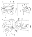
Figure 1 is a perspective view of a portion of a cable assembly in accordance with one embodiment before and after a crimping operation. -
Figure 2 is a plan view of an unformed crimp contact in accordance with one embodiment that may be used with the cable assembly ofFigure 1 . -
Figure 3 is a perspective view of a crimping system that is used during the crimping operation to manufacture the cable assembly ofFigure 1 . -
Figure 4 is a representative end view of a crimping applicator that may be used with the system ofFigure 3 . -
Figure 5 is a perspective view illustrating the crimping applicator and a crimp contact before a crimping operation. -
Figure 6 illustrates a first stage of the crimping operation in which the crimping applicator engages sidewalls of the crimp contact. -
Figure 7 illustrates a second stage of the crimping operation in which the crimping applicator begins to bend ends of the sidewalls radially inwardly. -
Figure 8 is a perspective view illustrating the crimping applicator and the crimp contact at an end of the crimping operation. -
Figure 9 shows different cross-sections of the crimp contact ofFigure 1 after the crimping operation for a first wire gauge. -
Figure 10 shows different cross-sections of the crimp contact ofFigure 1 after the crimping operation for a different second wire gauge. -
Figure 11 shows different cross-sections of the crimp contact ofFigure 1 after the crimping operation for a different third wire gauge. -
Figure 12 shows several cross-sectional images of a cable assembly formed in accordance with one embodiment. -
Figure 1 is a perspective view of a portion of acable assembly 100 in accordance with one embodiment before a crimping operation (referenced as 102) and after the crimping operation (referenced as 104). Thecable assembly 100 includes acrimp contact 105 and anelectrical wire 106 having aterminal end 108 that includes at least one exposedwire conductor 110. Theelectrical wire 106 may be used to transmit electrical power or data signals. Theelectrical wire 106 may have ajacket 107 that is removed (e.g., stripped) to expose thewire conductors 110. In the illustrated embodiment, theelectrical wire 106 includes sixteen wire conductors (or strands) 110, but theelectrical wire 106 may have fewer ormore wire conductors 110 in other embodiments. - In
Figure 1 , thecable assembly 100 is oriented with respect to a centrallongitudinal axis 190. Thelongitudinal axis 190 may extend through a geometric center of thecable assembly 100 after formation. Thecrimp contact 105 is configured to be deformed (e.g., crimped or crushed) during the crimping operation to grip thewire conductors 110 and thereby establish an electrical and mechanical connection between thewire conductors 110 and thecrimp contact 105. As shown inFigure 1 , thecrimp contact 105 only grips thewire conductors 110 of oneelectrical wire 106. In alternative embodiments, however, the wire conductors from separate electrical wires may be inserted into a channel of thecrimp contact 105 and pressed together (e.g., mechanically and electrically joined) within the channel through the crimping operation. - The
crimp contact 105 may be stamped and formed from conductive sheet material (e.g., metal). As described herein, thecrimp contact 105 may be dimensioned to grip a plurality of different wire gauges within a designated range. For example, thecrimp contact 105 may be dimensioned to grip cables or electrical wires having an American Wire Gauge (AWG) between 10-22 AWG (2.588 - 0.644 mm diameter). In particular embodiments, thecrimp contact 105 may be dimensioned to surround and grip wire conductors having a total cross-sectional area of X and, separately, to surround and grip wire conductors having a total cross-sectional area of at least about 3X or 5X or, more particularly, at least about 8X. As one non-limiting example, a first type of electrical wire may have wire conductors with a total (e.g., collective) cross-sectional area of about 0.75 mm2 and a second type of electrical wire may have wire conductors with a total cross-sectional area of at least about 5.00 mm2. Embodiments described herein may be configured to grip either of the first and second types. As another non-limiting example, a first type of electrical wire may have wire conductors with a total cross-sectional area of about 1.00 mm2 and a second type of electrical wire may have wire conductors with a total cross-sectional area of at least about 3.00 mm2. In the case of multiple wire conductors, each strand may have, by way of example only, radiuses of about 0.125 mm. However, the wire conductors may have other dimensions in alternative embodiments. -
Figure 2 is a plan view of thecrimp contact 105 after thecrimp contact 105 is stamped from sheet material but before being shaped for the crimping operation. With respect toFigures 1 and2 , thecrimp contact 105 has acontact body 114 that extends longitudinally between a leading edge or end 116 and a trailing edge or end 118. Thecontact body 114 has acontact length 130 that is measured along the longitudinal axis 190 (Figure 1 ). Thecontact body 114 has aninterior surface 150 and anexterior surface 152 that face in opposite directions and define a thickness 154 (Figure 1 ) of thecontact body 114 therebetween. In an exemplary embodiment, thethickness 154 is substantially uniform throughout, but may vary in other embodiments. Theinterior surface 150 is configured to directly engage thewire conductors 110. In some embodiments, a portion of theexterior surface 152 may also engage thewire conductors 110 after the crimping operation. - The
contact body 114 includes acenter portion 122 and opposite first andsecond sidewalls center portion 122. As shown inFigure 2 , thecontact body 114 has acenterline 160 that extends through a middle of thecenter portion 122. Thecenter portion 122 and thecenterline 160 may extend parallel to the longitudinal axis 190 (Figure 1 ). As shown inFigures 1 and2 , the first andsecond sidewalls second sidewalls - The first and
second sidewalls wire conductors 110. The first andsecond sidewalls first sidewall 124 has abase section 132 and aleg section 134, and thesecond sidewall 126 may also have abase section 142 and aleg section 144. The base andleg sections longitudinal edges leg sections longitudinal edges longitudinal edges longitudinal axis 190 in the illustrated embodiment. - As shown, the
leg section 134 and thebase section 142 are located along theleading edge 116, and theleg section 144 and thebase section 132 are located along the trailingedge 118. Theleg section 134 is defined between a portion of theleading edge 116 and aninterior edge 180. The leading andinterior edges longitudinal axis 190. Theinterior edge 180 extends between thelongitudinal edges leg section 144 is defined between a portion of the trailingedge 118 and aninterior edge 182. The leading andinterior edges longitudinal axis 190. Theinterior edge 182 extends between thelongitudinal edges interior edges longitudinal axis 190. The interior edges 180, 182 may also be characterized as extending along planes that are substantially orthogonal to thelongitudinal axis 190. As shown inFigures 1 and2 , theleg section 134 and thebase section 142 may be located opposite each other, and theleg section 144 and thebase section 132 may be located opposite each other. - With respect to
Figure 2 , the sections of the different sidewalls extend different lateral distances from thecenter portion 122 or thecenterline 160. For example, theleg section 134 extends alateral distance 135 from thecenterline 160 to thelongitudinal edge 164 of theleg section 134. Thebase section 132 extends alateral distance 133 from thecenterline 160 to thelongitudinal edge 162 of thebase section 132. Thelateral distance 135 of theleg section 134 is greater than thelateral distance 133 of thebase section 132. Likewise, theleg section 144 extends alateral distance 145 from thecenterline 160 to thelongitudinal edge 174 of theleg section 144. Thebase section 142 extends alateral distance 143 from thecenterline 160 to thelongitudinal edge 172 of thebase section 142. Accordingly, thecontact body 114 may have a staggered geometric configuration in which each of the longer leg sections directly opposes a shorter base section. - In the illustrated embodiment, the lateral distances 135 and 145 are substantially equal and the lateral distances 133 and 143 are substantially equal. In other embodiments, however, the lateral distances 135, 145 may not be equal and/or the lateral distances 133, 143 may not be equal. Also, in the illustrated embodiment, the
contact body 114 includes only two leg sections and only two base sections. In other embodiments, there may be more leg sections and/or base sections. For example, a third leg section may extend along the trailingedge 118 such that thebase section 132 is located between the third leg section and theleg section 134. A third base section may extend along the trailingedge 118 such that theleg section 144 is located between the third base section and thebase section 142. However, the contact body is not required to have opposing leg and base sections throughout. For example, in another alternative embodiment, third and fourth base sections may oppose each other along the trailingedge 118 with thecenterline 160 therebetween. - As shown in
Figure 2 , thelongitudinal edges section width 186. Thesection width 186 is measured along thelongitudinal axis 190. Each of thelongitudinal edges equal section width 186 as shown inFigure 2 . However, in other embodiments, thesection widths 186 may not be equal. - With respect to
Figure 1 , after the crimping operation, thecable assembly 100 may be mechanically and electrically connected to amating contact 112 during a mating operation. Themating contact 112 may have aprojection 121 that is configured to engage an electrical connector. In the illustrated embodiment, themating contact 112 defines acontact cavity 115 that is sized and shaped to receive theleading edge 116 of thecrimp contact 105. Thecrimp contact 105 may be advanced in a direction that is parallel to thelongitudinal axis 190 and inserted into thecontact cavity 115. In other embodiments, themating contact 112 may be similar to thecrimp contact 105 and folded around thecrimp contact 105. In yet another alternative embodiment, thecrimp contact 105 may be mechanically and electrically coupled to an electrical component by soldering thecrimp contact 105 to the other electrical contact. -
Figure 3 is a perspective view of a crimpingsystem 200 that may be used during the crimping operation to manufacture thecable assembly 100. The crimpingsystem 200 includes a crimpingapplicator 202, acontact support 204 that is configured to hold thecrimp contact 105, and anactuator 206, which is schematically represented as a box inFigure 3 . Theactuator 206 may be operably coupled to the crimpingapplicator 202 and/or thecontact support 204. Theactuator 206 may be, for example, a linear motor that is configured to drive at least one of the crimpingapplicator 202 or thecontact support 204 toward the other with thecrimp contact 105 therebetween. In the illustrated embodiment, the crimpingapplicator 202 is moved in a linear direction by theactuator 206 toward thecontact support 204. In alternative embodiments, thecontact support 204 may be moved toward the crimpingapplicator 202, or each of thecontact support 204 and the crimpingapplicator 202 may be moved toward each other. Thecrimp contact 105 is configured to be deformed by the crimpingapplicator 202 and thecontact support 204 while holding thewire conductors 110. -
Figure 4 is a representative end view of the crimpingapplicator 202. With respect toFigures 3 and 4 , the crimpingapplicator 202 includes leading and trailingportions Figure 4 , the leadingportion 208 is represented as a solid line, and the trailingportion 210 is represented as a dashed line. The leadingportion 208 is configured to engage the leg andbase sections 134, 142 (Figure 3 ), and the trailingportion 210 is configured to engage the leg andbase sections 144, 132 (Figure 3 ). The leading and trailingportions - The crimping
applicator 202 defines opposing first and second contouredwalls contoured wall 220 is configured to initially engage the first sidewall 124 (Figure 3 ), and the secondcontoured wall 222 is configured to initially engage the second sidewall 126 (Figure 3 ). The leading and trailingportions respective wall portions contoured wall 220 andrespective wall portions 238, 240 (Figure 4 ) that define the secondcontoured wall 222. - The leading and trailing
portions features features portions crimp contact 105. The wall-bendingfeatures Figures 5-8 , the wall-bendingfeature 224 is configured to more sharply bend theleg section 134 than thebase section 142, and the wall-bendingfeature 226 is configured to more sharply bend theleg section 144 than thebase section 132. As shown inFigure 4 , the wall bending features 224, 226 have respective apexes A1, A2 that are laterally offset from each other. Accordingly, the wall-bendingfeatures discontinuous joint 250 of the crimpingapplicator 202. -
Figures 5-8 illustrate the crimping operation for one embodiment. As shown inFigure 5 , thecenter portion 122 and the first andsecond sidewalls crimp contact 105 may define a conductor-receivingchannel 252 that is configured to receive at least one wire conductor. The conductor-receivingchannel 252 may hold numerous wire conductors 110 (e.g., five or more wire conductors). Thecrimp contact 105 is positioned on thecontact support 204 such that thecrimp contact 105 is located between thecontact support 204 and the crimpingapplicator 202. As shown, theleg sections contact support 204, and thebase sections contact support 204. The first height H1 is greater than the second height H2. In alternative embodiments, theleg sections base sections - As shown in
Figure 6 , during a first crimping stage the first and second contouredwalls second sidewalls second sidewalls wall portion 228 of the leadingportion 208 may engage theleg section 134, and thewall portion 230 of the trailingportion 210 may engage theleg section 144. In the first crimping stage, the first andsecond sidewalls -
Figure 7 illustrates a second crimping stage. During the second crimping stage, theleg sections features Figure 5 ), 142 engaging the wall-bendingfeatures features leg sections leg section 134 is bent so that thelongitudinal edges 164 slides under thelongitudinal edge 172. As shown inFigure 8 , thelongitudinal edge 164 is located under thelongitudinal edge 172 within acontact cavity 254 that is defined by thedeformed crimp contact 105. Although not shown, thelongitudinal edge 174 of theleg section 144 is located under thelongitudinal edge 162 of thebase section 132 within thecontact cavity 254. As such, portions of theleg sections contact cavity 254 after thecrimp contact 105 is deformed. - Accordingly, the
leg section 134 of thefirst sidewall 124 may interface with theopposite base section 142 of thesecond sidewall 126, and theleg section 144 of thesecond sidewall 126 may interface with theopposite base section 132 of thefirst sidewall 124. A leg section may interface with a base section when the longitudinal edge of the leg section or the exterior surface of the leg section is located proximate to the longitudinal edge of the opposite base section. For example, as shown inFigure 8 , theexterior surface 152 along theleg section 134 engages thelongitudinal edge 172 of thebase section 142. In other embodiments, thelongitudinal edge 164 may be located proximate to (e.g., engage or be slightly spaced apart) thelongitudinal edge 172 of thebase section 142. -
Figures 9-11 illustrate cross-sections of thecrimp contact 105 for electrical wires with different wire gauges. For example,Figure 9 illustrates three cross-sections C1, C2, and C3 that are taken at different longitudinal locations along thecrimp contact 105. InFigure 9 , the wire gauge of the electrical wire 106 (Figure 1 ) is 18 AWG (1.024 mm diameter). The longitudinal locations of the cross-sections may be as shown inFigure 1 . More specifically, C1 may extend through thebase section 132 and the leg section 144 (or proximate to the trailing edge 118); C2 may extend approximately along aninterface 260 between theinterior edges 180, 182 (Figure 2 ); and C3 may extend through thebase section 142 and the leg section 134 (or proximate to the leading edge 116). - In some embodiments, the configurations of the first and
second sidewalls contact cavity 254 when thecrimp contact 105 is deformed. For instance, by comparing the cross-sections C1, C2, and C3, it is shown that theleg sections wire conductors 110. A first arrangement of wire conductors is different from a second arrangement if at least one of the wire conductors in the first arrangement is not within the second arrangement or vice versa. For example, as shown in the cross-section C1, thewire conductors leg section 144. In the cross-section C3, thewire conductors leg section 134. For illustration, thewire conductors wire conductors 110A-110H have different locations with thecontact cavity 254 than in the cross-sections C1 and C3. Thus, theleg sections wire conductors 110. InFigure 9 , theleg sections wire conductor 110A. In other embodiments, however, theleg sections - This varying conductor distribution may cause multiple different contact points where the
interior surface 150 of thecrimp contact 105 engages thewire conductors 110 thereby increasing the friction between thewire conductors 110 and theinterior surface 150. As such, a greater tensile force to remove thewire conductors 110 from thecrimp contact 105 may be required. Moreover, the changing orientation or position ofindividual wire conductors 110 may cause a greater frictional force than other known crimp contacts and, as such, would require a greater tensile force to remove the wire conductors. For example, in an exemplary embodiment, thecommon wire conductor 110A wraps between theinterior edges electrical wire 106 was inadvertently pulled away from thecrimp contact 105 after thecrimp contact 105 was deformed, the configuration of thewire conductor 110A and theinterior edge 182 may cause a greater frictional force that would prevent the withdrawal. Accordingly, thecrimp contact 105 may provide greater resistance to inadvertent removal of thewire conductors 110 than other known crimp contacts. - In
Figure 10 , the wire gauge of the electrical wire (not shown) that includes thewire conductors 310 is 10 AWG (2.588 mm diameter). Cross-sections C4, C5, and C6 are shown and may have similar longitudinal locations as the cross-sections C1, C2, and C3, respectively. As shown, a cross-sectional area of thewire conductors 310 is greater than a cross-sectional area of thewire conductors 110 shown inFigure 9 . Due to the cross-sectional area of thewire conductors 310, theleg sections base sections longitudinal edges longitudinal edges - In
Figure 11 , the wire gauge of the electrical wire (not shown) that includes thewire conductors 410 is 10 AWG (2.588 mm diameter). Cross-sections C7, C8, and C9 are shown and may have similar longitudinal locations as the cross-sections C1, C2, and C3, respectively. As shown, a cross-sectional area of thewire conductors 410 is less than the cross-sectional area of the wire conductors 110 (Figure 9 ) and less than the cross-sectional area of thewire conductors 310. During the crimping operation, thecrimp contact 105 may be deformed in a similar manner as the embodiment that includes thewire conductors 110. For example, theleg section 144 may slide under thebase section 132 as shown in the cross-section C7, and theleg section 134 may slide under thebase section 142 as shown in the cross-section C9. Accordingly, portions of theleg sections contact cavity 254 after thecrimp contact 105 is deformed. In the embodiment ofFigure 11 , all of thewire conductors 410 are surrounded by theleg section 144 and all of thewire conductors 410 are surrounded by theleg section 134. - In
Figure 11 , the conductor distribution within thecontact cavity 254 shows an even greater lateral shifting of thewire conductors 410 than the lateral shifting of thewire conductors 110 inFigure 9 . By comparing the cross-sections C7, C8, and C9, it is shown that thewire conductors 410 are immediately surrounded by thefirst sidewall 124 for a first portion of the contact length 130 (Figure 1 ) and immediately surrounded by thesecond sidewall 126 for a second portion of thecontact length 130. -
Figure 12 shows a series of cross-sectional images 501-510 of acable assembly 500 formed in accordance with one embodiment. The wire gauge of the electrical wire inFigure 12 is 18 AWG (1.024 mm diameter). The cross-sectional images 501-510 of thecable assembly 500 were captured along a series of longitudinal locations (in the order as shown inFigure 12 ). Theimage 501 is proximate to the trailing edge, and theimage 510 is proximate to the leading edge. In other embodiments, however, theimage 501 may be proximate to the leading edge and theimage 510 may be proximate to the trailing edge. The images 505-507 are proximate to the interface between interior edges as described above. As shown, the crimp contact may securely grip the wire conductors within the contact cavity as described in other embodiments. - Accordingly, the crimp contacts described herein may be configured to grip the wire conductors of electrical wires having a greater range of wire gauges than known crimp contacts. In addition, the crimp contacts may enable a greater gripping or compressive force caused by an increase in friction between the interior surface of the crimp contact and the wire conductors within the contact cavity of the crimp contact. In order to remove the wire conductors, a greater withdrawal force may be required to overcome the gripping force.
- It is to be understood that the above description is intended to be illustrative, and not restrictive. For example, the above-described embodiments (and/or aspects thereof) may be used in combination with each other. In addition, many modifications may be made to adapt a particular situation or material to the teachings of the invention without departing from its scope. Dimensions, types of materials, orientations of the various components, and the number and positions of the various components described herein are intended to define parameters of certain embodiments, and are by no means limiting and are merely exemplary embodiments. Many other embodiments and modifications within the scope of the claims will be apparent to those of skill in the art upon reviewing the above description. The scope of the subject matter described and/or illustrated herein should, therefore, be determined with reference to the appended claims, along with the full scope of equivalents to which such claims are entitled. In the appended claims, the terms "including" and "in which" are used as the plain-English equivalents of the respective terms "comprising" and "wherein." Moreover, in the following claims, the terms "first," "second," and "third," etc. are used merely as labels, and are not intended to impose numerical requirements on their objects.
Claims (15)
- A cable assembly (100) comprising:a electrical wire (106) having a terminal end (108) that includes at least one exposed wire conductor (110); anda crimp contact (105) having a centerline (160) and first and second sidewalls (124, 126) that extend from the centerline in opposite directions, the centerline (160) extending parallel to a longitudinal axis (190) of the crimp contact (105), each of the first and second sidewalls having a base section (132, 142) and a leg section (134, 144), the leg section (134, 144) extending a lateral distance (135, 145) from the centerline (160) to a longitudinal edge (164, 174) of the leg section, the base section (132, 142) extending a lateral distance (133, 143) from the centerline (160) to a longitudinal edge (162, 172) of the base section, the lateral distance (135, 145) of the leg section (134, 144) being greater than the lateral distance (133, 143) of the base section (132, 142) for each of the first and second sidewalls (124, 126), the leg section (134) of the first sidewall (124) being located opposite the base section (142) of the second sidewall (126), the leg section (144) of the second sidewall (126) being located opposite the base section (132) of the first sidewall (124), wherein the first and second sidewalls (124, 126) surround and engage the at least one wire conductor (110).
- The cable assembly (100) of claim 1, wherein the leg section (134) of the first sidewall (124) interfaces with the base section (142) of the second sidewall (126), the leg section (144) of the second sidewall (126) interfacing with the base section (132) of the first sidewall (124).
- The cable assembly (100) of claim 2, wherein the leg section (134, 144) of one of the sidewalls (124, 126) is folded under the base section (142, 132) of the opposite sidewall such that an exterior surface (152) of the leg section interfaces with the base section.
- The cable assembly (100) of claim 2, wherein the longitudinal edge (164, 174) of the leg section (134, 144) of one of the sidewalls (124, 126) interfaces with the longitudinal edge (172, 162) of the base section (142, 132) of the opposite sidewall.
- The cable assembly (100) of any preceding claim, further comprising a mating contact (112), the crimp contact (105) extending longitudinally between leading and trailing edges (116, 118) in which the trailing edge (118) is proximate to the electrical wire (106), the mating contact (112) being mechanically and electrically coupled to the crimp contact (105) at the leading edge (116) of the crimp contact.
- The cable assembly (100) of any preceding claim, wherein the crimp contact (105) has a contact length (130) that extends along the longitudinal axis (190), the at least one wire conductor (410) being immediately surrounded by the first sidewall (124) for a first portion of the contact length (130) and immediately surrounded by the second sidewall (126) for a second portion of the contact length.
- The cable assembly (100) of any preceding claim, wherein the at least one wire conductor (110) has a varying conductor density or distribution within the crimp contact (105) as the crimp contact extends from a leading edge (116) of the crimp contact to the electrical wire (106).
- The cable assembly (100) of any preceding claim, wherein the at least one wire conductor (110) includes numerous wire conductors, each of the leg sections (134, 144) of the first and second sidewalls (124, 126) surrounding a plurality of the wire conductors.
- The cable assembly (100) of any one of claims 1 to 7, wherein the at least one wire conductor (110) includes numerous wire conductors, each of the leg sections (134, 144) of the first and second sidewalls (124, 126) surrounding at least one common wire conductor (110).
- The cable assembly (100) of any one of claims 1 to 7, wherein the at least one wire conductor (110) includes numerous wire conductors, each of the leg sections (134, 144) of the first and second sidewalls (124, 126) surrounding different arrangements of the wire conductors.
- A crimp contact (105) comprising:a contact body (114) having a centerline (160) and first and second sidewalls (124, 126) that extend from the centerline in opposite directions, the centerline (160) extending parallel to a longitudinal axis (190) of the crimp contact (105), each of the first and second sidewalls having a base section (132, 142) and a leg section (134, 144), the leg section (134, 144) extending a lateral distance (135, 145) from the centerline (160) to a longitudinal edge (164, 174) of the leg section, the base section (132, 142) extending a lateral distance (133, 143) from the centerline (160) to a longitudinal edge (162, 172) of the base section, the lateral distance (135, 145) of the leg section (134, 144) being greater than the lateral distance (133, 143) of the base section (132, 142) for each of the first and second sidewalls (124, 126), the leg section (134) of the first sidewall (124) being located opposite the base section (142) of the second sidewall (126), the leg section (144) of the second sidewall (126) being located opposite the base section (132) of the first sidewall (124).
- The crimp contact (105) of claim 11, wherein the crimp contact is dimensioned to surround and engage at least one wire conductor (110) having a total cross-sectional area of X and, separately, to surround and engage at least one wire conductor having a total cross-sectional area of at least about 3X.
- The crimp contact (105) of claim 11, wherein the crimp contact is dimensioned to surround and engage at least one wire conductor (110) having a total cross-sectional area of about 0.75 mm2 and, separately, to surround and engage at least one wire conductor having a total cross-sectional area of at least about 5.00 mm2.
- The crimp contact (105) of claim 11, 12 or 13, wherein the leg section (134) of the first sidewall (124) is capable of interfacing with the base section (142) of the second sidewall (126) when the crimp contact (105) is deformed to engage at least one wire conductor (110), the leg section (144) of the second sidewall (126) being capable of interfacing with the base section (132) of the first sidewall (124) when the crimp contact (105) is deformed to engage the least one wire conductor (110).
- The crimp contact (105) of any one of claims 11 to 14, wherein the leg section (134, 144) of one of the sidewalls (124, 126) is capable of being folded under the base section (142, 132) of the opposite sidewall when the crimp contact (105) is deformed to engage the at least one wire conductor (110).
Applications Claiming Priority (1)
| Application Number | Priority Date | Filing Date | Title |
|---|---|---|---|
| US13/739,233 US9343820B2 (en) | 2013-01-11 | 2013-01-11 | Crimp contact and cable assembly including the same |
Publications (2)
| Publication Number | Publication Date |
|---|---|
| EP2755280A1 true EP2755280A1 (en) | 2014-07-16 |
| EP2755280B1 EP2755280B1 (en) | 2017-03-15 |
Family
ID=49958251
Family Applications (1)
| Application Number | Title | Priority Date | Filing Date |
|---|---|---|---|
| EP14150486.0A Active EP2755280B1 (en) | 2013-01-11 | 2014-01-08 | Crimp contact and cable assembly including the same |
Country Status (8)
| Country | Link |
|---|---|
| US (1) | US9343820B2 (en) |
| EP (1) | EP2755280B1 (en) |
| JP (3) | JP2014135279A (en) |
| KR (1) | KR102233840B1 (en) |
| CN (1) | CN103928776B (en) |
| BR (1) | BR102014000557B8 (en) |
| MX (1) | MX339295B (en) |
| TW (1) | TWI613871B (en) |
Cited By (1)
| Publication number | Priority date | Publication date | Assignee | Title |
|---|---|---|---|---|
| EP3706247A3 (en) * | 2019-03-06 | 2020-11-25 | Tyco Electronics (Shanghai) Co., Ltd. | Connection terminal |
Families Citing this family (7)
| Publication number | Priority date | Publication date | Assignee | Title |
|---|---|---|---|---|
| JP6609136B2 (en) * | 2015-07-28 | 2019-11-20 | 株式会社白山 | Crimp connection structure, crimp connection device, and crimp connection method |
| JP6766437B2 (en) * | 2016-05-10 | 2020-10-14 | 株式会社オートネットワーク技術研究所 | Wires with terminals and terminals |
| JP6709806B2 (en) * | 2018-01-18 | 2020-06-17 | 矢崎総業株式会社 | Crimper |
| DE102019109460A1 (en) * | 2019-04-10 | 2020-10-15 | Te Connectivity Germany Gmbh | Crimp contact |
| JP7060002B2 (en) * | 2019-11-20 | 2022-04-26 | 日立金属株式会社 | Multi-core cable |
| US11600937B2 (en) * | 2020-07-02 | 2023-03-07 | Te Connectivity Solutions Gmbh | Electrical terminal for flat flexible cables |
| JP7447749B2 (en) * | 2020-09-16 | 2024-03-12 | 住友電装株式会社 | Electric wire with terminal |
Citations (3)
| Publication number | Priority date | Publication date | Assignee | Title |
|---|---|---|---|---|
| GB844727A (en) * | 1957-09-19 | 1960-08-17 | Gen Motors Corp | Improvements in or relating to electrical connector assemblies |
| GB2275879A (en) * | 1993-03-08 | 1994-09-14 | Sumitomo Wall Systems Ltd | Terminal crimping method and crimp terminal used therefor |
| US20060057904A1 (en) * | 2004-09-13 | 2006-03-16 | Yazaki Corporation | Jointing sleeve component and joint electric wire |
Family Cites Families (31)
| Publication number | Priority date | Publication date | Assignee | Title |
|---|---|---|---|---|
| US2600012A (en) * | 1946-06-27 | 1952-06-10 | Aircraft Marine Prod Inc | Electrical connector |
| US2557126A (en) * | 1946-06-27 | 1951-06-19 | Aircraft Marine Prod Inc | Electrical connector |
| US2617845A (en) * | 1947-10-16 | 1952-11-11 | Aircraft Marine Prod Inc | Terminal with insulation piercing ferrule |
| US2799841A (en) * | 1951-06-16 | 1957-07-16 | Amp Inc | Electrical connector and method of its manufacture and use |
| JPS5443350Y2 (en) * | 1972-12-15 | 1979-12-14 | ||
| JPS5630145B2 (en) * | 1973-09-17 | 1981-07-13 | ||
| US3964815A (en) * | 1975-02-26 | 1976-06-22 | Molex Incorporated | Insulation piercing terminal |
| JPS5630145Y2 (en) * | 1975-12-09 | 1981-07-17 | ||
| JPS5577369U (en) * | 1978-11-22 | 1980-05-28 | ||
| JPH06260218A (en) * | 1993-03-04 | 1994-09-16 | Sumitomo Wiring Syst Ltd | Electric wire connection method |
| FR2730864B3 (en) * | 1995-02-17 | 1997-04-30 | Amp France | ONE-PIECE ELECTRIC FEMALE TERMINAL |
| CN2372805Y (en) * | 1999-02-08 | 2000-04-05 | 黄志雄 | Covered terminal device |
| US6626711B2 (en) * | 2000-06-12 | 2003-09-30 | Yazaki Corporation | Press-clamping terminal and method of examining press-clamped condition thereof |
| US6676458B2 (en) * | 2000-09-21 | 2004-01-13 | Yazaki Corporation | Structure and method for connecting terminal and electric wire |
| JP2003151667A (en) * | 2001-11-13 | 2003-05-23 | Furukawa Electric Co Ltd:The | Connection terminal for flat cable and connection between flat cable and connection terminal |
| JP2003249285A (en) * | 2002-02-25 | 2003-09-05 | Auto Network Gijutsu Kenkyusho:Kk | Aluminum wire terminal connection structure |
| JP2003249284A (en) * | 2002-02-25 | 2003-09-05 | Auto Network Gijutsu Kenkyusho:Kk | Crimp terminal for aluminum wire |
| TWM242870U (en) * | 2003-08-22 | 2004-09-01 | Jr-Shiung Huang | Improved wrapped terminal structure |
| CN2665969Y (en) * | 2003-09-08 | 2004-12-22 | 黄志雄 | Cladding terminal structure |
| JP4250103B2 (en) * | 2004-03-12 | 2009-04-08 | Smk株式会社 | Crimping device |
| US7803008B2 (en) * | 2007-11-27 | 2010-09-28 | Yazaki Corporation | Press-clamping structure and press-clamping terminal |
| EP2266170B1 (en) * | 2008-03-20 | 2016-11-16 | Delphi International Operations Luxembourg S.à r.l. | Electric terminal crimping method and assembly obtained |
| JP5249615B2 (en) * | 2008-03-24 | 2013-07-31 | 矢崎総業株式会社 | Crimp terminal for aluminum wire |
| JP5065124B2 (en) * | 2008-03-31 | 2012-10-31 | 古河電気工業株式会社 | Crimp terminal |
| JP2009272141A (en) * | 2008-05-07 | 2009-11-19 | Autonetworks Technologies Ltd | Crimping terminal, and method for manufacturing of electric cable with terminal |
| JP5225794B2 (en) * | 2008-09-16 | 2013-07-03 | 矢崎総業株式会社 | Crimp structure of crimp terminal |
| JP5195230B2 (en) * | 2008-09-26 | 2013-05-08 | 住友電装株式会社 | Electric wire with terminal bracket |
| JP5147648B2 (en) * | 2008-11-07 | 2013-02-20 | 矢崎総業株式会社 | Crimp terminal and wire fixing structure in crimp terminal |
| JP5464744B2 (en) * | 2010-03-12 | 2014-04-09 | 日本航空電子工業株式会社 | contact |
| JP5138118B2 (en) * | 2010-12-08 | 2013-02-06 | 古河電気工業株式会社 | Crimp terminal, connection structure, and manufacturing method thereof |
| JP5601259B2 (en) * | 2011-03-24 | 2014-10-08 | 住友電装株式会社 | Terminal fitting |
-
2013
- 2013-01-11 US US13/739,233 patent/US9343820B2/en active Active
-
2014
- 2014-01-08 JP JP2014001548A patent/JP2014135279A/en not_active Withdrawn
- 2014-01-08 EP EP14150486.0A patent/EP2755280B1/en active Active
- 2014-01-09 BR BR102014000557A patent/BR102014000557B8/en active IP Right Grant
- 2014-01-10 TW TW103100926A patent/TWI613871B/en active
- 2014-01-10 KR KR1020140003592A patent/KR102233840B1/en active Active
- 2014-01-10 MX MX2014000477A patent/MX339295B/en active IP Right Grant
- 2014-01-13 CN CN201410085484.4A patent/CN103928776B/en active Active
-
2018
- 2018-08-23 JP JP2018155981A patent/JP6685353B2/en active Active
-
2020
- 2020-03-30 JP JP2020059575A patent/JP6921262B2/en active Active
Patent Citations (3)
| Publication number | Priority date | Publication date | Assignee | Title |
|---|---|---|---|---|
| GB844727A (en) * | 1957-09-19 | 1960-08-17 | Gen Motors Corp | Improvements in or relating to electrical connector assemblies |
| GB2275879A (en) * | 1993-03-08 | 1994-09-14 | Sumitomo Wall Systems Ltd | Terminal crimping method and crimp terminal used therefor |
| US20060057904A1 (en) * | 2004-09-13 | 2006-03-16 | Yazaki Corporation | Jointing sleeve component and joint electric wire |
Cited By (1)
| Publication number | Priority date | Publication date | Assignee | Title |
|---|---|---|---|---|
| EP3706247A3 (en) * | 2019-03-06 | 2020-11-25 | Tyco Electronics (Shanghai) Co., Ltd. | Connection terminal |
Also Published As
| Publication number | Publication date |
|---|---|
| JP6685353B2 (en) | 2020-04-22 |
| JP2020107615A (en) | 2020-07-09 |
| BR102014000557A2 (en) | 2015-12-22 |
| BR102014000557B1 (en) | 2021-08-10 |
| US9343820B2 (en) | 2016-05-17 |
| KR20140091490A (en) | 2014-07-21 |
| CN103928776B (en) | 2018-04-10 |
| MX2014000477A (en) | 2015-05-01 |
| BR102014000557B8 (en) | 2021-09-08 |
| JP6921262B2 (en) | 2021-08-18 |
| JP2018181860A (en) | 2018-11-15 |
| MX339295B (en) | 2016-05-19 |
| TW201444206A (en) | 2014-11-16 |
| US20140199897A1 (en) | 2014-07-17 |
| JP2014135279A (en) | 2014-07-24 |
| CN103928776A (en) | 2014-07-16 |
| KR102233840B1 (en) | 2021-03-30 |
| TWI613871B (en) | 2018-02-01 |
| EP2755280B1 (en) | 2017-03-15 |
Similar Documents
| Publication | Publication Date | Title |
|---|---|---|
| EP2755280B1 (en) | Crimp contact and cable assembly including the same | |
| US8834215B2 (en) | Electrical contact element | |
| US9484640B2 (en) | Wire with a crimp terminal with a bottom plate with an inclined portion and a raised portion | |
| KR102521413B1 (en) | A method for crimping an electrical contact to a cable and a tool for carrying out the method | |
| US11152718B2 (en) | Electrical cable including terminal having pressing portion that presses holding portion | |
| EP2159880A1 (en) | A terminal fitting and a wire connected with a terminal fitting | |
| US20200287300A1 (en) | Connection Terminal, Method Of Connecting Wires Using The Same And Pressing Die | |
| US7316581B2 (en) | Terminal fitting and method of attaching the same | |
| US9088079B2 (en) | Crimped terminal attached electric wire and method of crimping crimped terminal to electric wire | |
| WO2020196706A1 (en) | Crimping terminal, electric wire provided with crimping terminal, and method for manufacturing crimping terminal | |
| CN109565140B (en) | Crimping tool and terminals obtained using the crimping tool | |
| KR102338051B1 (en) | Coaxial Connectors and Coaxial Connectors with Coaxial Cables | |
| CN113169474A (en) | Socket contact elements for conductive connections | |
| EP3989364A1 (en) | Electrical crimp terminal | |
| US12525732B2 (en) | Electrical cable or electrical line configured with a plug-in contour for plugging directly into a mating plug | |
| US11489307B1 (en) | Method of crimping an electrical terminal onto a flat flexible cable | |
| US20230007908A1 (en) | Electrical terminal with crimped connection to a flat flexible cable | |
| JP2013073877A (en) | Terminal and cable connection method of terminal | |
| EP3783744A1 (en) | Electric connection arrangement | |
| EP4528941A1 (en) | Electrical contact terminal with a crimp portion and assembling method thereof | |
| US20210104823A1 (en) | Conductive member |
Legal Events
| Date | Code | Title | Description |
|---|---|---|---|
| PUAI | Public reference made under article 153(3) epc to a published international application that has entered the european phase |
Free format text: ORIGINAL CODE: 0009012 |
|
| 17P | Request for examination filed |
Effective date: 20140108 |
|
| AK | Designated contracting states |
Kind code of ref document: A1 Designated state(s): AL AT BE BG CH CY CZ DE DK EE ES FI FR GB GR HR HU IE IS IT LI LT LU LV MC MK MT NL NO PL PT RO RS SE SI SK SM TR |
|
| AX | Request for extension of the european patent |
Extension state: BA ME |
|
| R17P | Request for examination filed (corrected) |
Effective date: 20150109 |
|
| RBV | Designated contracting states (corrected) |
Designated state(s): AL AT BE BG CH CY CZ DE DK EE ES FI FR GB GR HR HU IE IS IT LI LT LU LV MC MK MT NL NO PL PT RO RS SE SI SK SM TR |
|
| RIC1 | Information provided on ipc code assigned before grant |
Ipc: H01R 43/058 20060101ALN20150929BHEP Ipc: H01R 4/18 20060101AFI20150929BHEP |
|
| 17Q | First examination report despatched |
Effective date: 20151014 |
|
| GRAP | Despatch of communication of intention to grant a patent |
Free format text: ORIGINAL CODE: EPIDOSNIGR1 |
|
| RIC1 | Information provided on ipc code assigned before grant |
Ipc: H01R 4/18 20060101AFI20160818BHEP Ipc: H01R 43/058 20060101ALN20160818BHEP |
|
| RIC1 | Information provided on ipc code assigned before grant |
Ipc: H01R 4/18 20060101AFI20160831BHEP Ipc: H01R 43/058 20060101ALN20160831BHEP |
|
| INTG | Intention to grant announced |
Effective date: 20160922 |
|
| GRAS | Grant fee paid |
Free format text: ORIGINAL CODE: EPIDOSNIGR3 |
|
| GRAA | (expected) grant |
Free format text: ORIGINAL CODE: 0009210 |
|
| RAP1 | Party data changed (applicant data changed or rights of an application transferred) |
Owner name: TE CONNECTIVITY CORPORATION |
|
| AK | Designated contracting states |
Kind code of ref document: B1 Designated state(s): AL AT BE BG CH CY CZ DE DK EE ES FI FR GB GR HR HU IE IS IT LI LT LU LV MC MK MT NL NO PL PT RO RS SE SI SK SM TR |
|
| REG | Reference to a national code |
Ref country code: CH Ref legal event code: EP Ref country code: GB Ref legal event code: FG4D |
|
| REG | Reference to a national code |
Ref country code: IE Ref legal event code: FG4D |
|
| REG | Reference to a national code |
Ref country code: AT Ref legal event code: REF Ref document number: 876423 Country of ref document: AT Kind code of ref document: T Effective date: 20170415 |
|
| REG | Reference to a national code |
Ref country code: DE Ref legal event code: R096 Ref document number: 602014007483 Country of ref document: DE |
|
| REG | Reference to a national code |
Ref country code: NL Ref legal event code: MP Effective date: 20170315 |
|
| REG | Reference to a national code |
Ref country code: LT Ref legal event code: MG4D |
|
| PG25 | Lapsed in a contracting state [announced via postgrant information from national office to epo] |
Ref country code: FI Free format text: LAPSE BECAUSE OF FAILURE TO SUBMIT A TRANSLATION OF THE DESCRIPTION OR TO PAY THE FEE WITHIN THE PRESCRIBED TIME-LIMIT Effective date: 20170315 Ref country code: LT Free format text: LAPSE BECAUSE OF FAILURE TO SUBMIT A TRANSLATION OF THE DESCRIPTION OR TO PAY THE FEE WITHIN THE PRESCRIBED TIME-LIMIT Effective date: 20170315 Ref country code: GR Free format text: LAPSE BECAUSE OF FAILURE TO SUBMIT A TRANSLATION OF THE DESCRIPTION OR TO PAY THE FEE WITHIN THE PRESCRIBED TIME-LIMIT Effective date: 20170616 Ref country code: HR Free format text: LAPSE BECAUSE OF FAILURE TO SUBMIT A TRANSLATION OF THE DESCRIPTION OR TO PAY THE FEE WITHIN THE PRESCRIBED TIME-LIMIT Effective date: 20170315 Ref country code: NO Free format text: LAPSE BECAUSE OF FAILURE TO SUBMIT A TRANSLATION OF THE DESCRIPTION OR TO PAY THE FEE WITHIN THE PRESCRIBED TIME-LIMIT Effective date: 20170615 |
|
| REG | Reference to a national code |
Ref country code: AT Ref legal event code: MK05 Ref document number: 876423 Country of ref document: AT Kind code of ref document: T Effective date: 20170315 |
|
| PG25 | Lapsed in a contracting state [announced via postgrant information from national office to epo] |
Ref country code: BG Free format text: LAPSE BECAUSE OF FAILURE TO SUBMIT A TRANSLATION OF THE DESCRIPTION OR TO PAY THE FEE WITHIN THE PRESCRIBED TIME-LIMIT Effective date: 20170615 Ref country code: SE Free format text: LAPSE BECAUSE OF FAILURE TO SUBMIT A TRANSLATION OF THE DESCRIPTION OR TO PAY THE FEE WITHIN THE PRESCRIBED TIME-LIMIT Effective date: 20170315 Ref country code: LV Free format text: LAPSE BECAUSE OF FAILURE TO SUBMIT A TRANSLATION OF THE DESCRIPTION OR TO PAY THE FEE WITHIN THE PRESCRIBED TIME-LIMIT Effective date: 20170315 Ref country code: RS Free format text: LAPSE BECAUSE OF FAILURE TO SUBMIT A TRANSLATION OF THE DESCRIPTION OR TO PAY THE FEE WITHIN THE PRESCRIBED TIME-LIMIT Effective date: 20170315 |
|
| PG25 | Lapsed in a contracting state [announced via postgrant information from national office to epo] |
Ref country code: NL Free format text: LAPSE BECAUSE OF FAILURE TO SUBMIT A TRANSLATION OF THE DESCRIPTION OR TO PAY THE FEE WITHIN THE PRESCRIBED TIME-LIMIT Effective date: 20170315 |
|
| PG25 | Lapsed in a contracting state [announced via postgrant information from national office to epo] |
Ref country code: CZ Free format text: LAPSE BECAUSE OF FAILURE TO SUBMIT A TRANSLATION OF THE DESCRIPTION OR TO PAY THE FEE WITHIN THE PRESCRIBED TIME-LIMIT Effective date: 20170315 Ref country code: EE Free format text: LAPSE BECAUSE OF FAILURE TO SUBMIT A TRANSLATION OF THE DESCRIPTION OR TO PAY THE FEE WITHIN THE PRESCRIBED TIME-LIMIT Effective date: 20170315 Ref country code: AT Free format text: LAPSE BECAUSE OF FAILURE TO SUBMIT A TRANSLATION OF THE DESCRIPTION OR TO PAY THE FEE WITHIN THE PRESCRIBED TIME-LIMIT Effective date: 20170315 Ref country code: ES Free format text: LAPSE BECAUSE OF FAILURE TO SUBMIT A TRANSLATION OF THE DESCRIPTION OR TO PAY THE FEE WITHIN THE PRESCRIBED TIME-LIMIT Effective date: 20170315 Ref country code: SK Free format text: LAPSE BECAUSE OF FAILURE TO SUBMIT A TRANSLATION OF THE DESCRIPTION OR TO PAY THE FEE WITHIN THE PRESCRIBED TIME-LIMIT Effective date: 20170315 Ref country code: RO Free format text: LAPSE BECAUSE OF FAILURE TO SUBMIT A TRANSLATION OF THE DESCRIPTION OR TO PAY THE FEE WITHIN THE PRESCRIBED TIME-LIMIT Effective date: 20170315 |
|
| PG25 | Lapsed in a contracting state [announced via postgrant information from national office to epo] |
Ref country code: PL Free format text: LAPSE BECAUSE OF FAILURE TO SUBMIT A TRANSLATION OF THE DESCRIPTION OR TO PAY THE FEE WITHIN THE PRESCRIBED TIME-LIMIT Effective date: 20170315 Ref country code: PT Free format text: LAPSE BECAUSE OF FAILURE TO SUBMIT A TRANSLATION OF THE DESCRIPTION OR TO PAY THE FEE WITHIN THE PRESCRIBED TIME-LIMIT Effective date: 20170717 Ref country code: SM Free format text: LAPSE BECAUSE OF FAILURE TO SUBMIT A TRANSLATION OF THE DESCRIPTION OR TO PAY THE FEE WITHIN THE PRESCRIBED TIME-LIMIT Effective date: 20170315 Ref country code: IS Free format text: LAPSE BECAUSE OF FAILURE TO SUBMIT A TRANSLATION OF THE DESCRIPTION OR TO PAY THE FEE WITHIN THE PRESCRIBED TIME-LIMIT Effective date: 20170715 |
|
| REG | Reference to a national code |
Ref country code: FR Ref legal event code: PLFP Year of fee payment: 5 |
|
| REG | Reference to a national code |
Ref country code: DE Ref legal event code: R097 Ref document number: 602014007483 Country of ref document: DE |
|
| PLBE | No opposition filed within time limit |
Free format text: ORIGINAL CODE: 0009261 |
|
| STAA | Information on the status of an ep patent application or granted ep patent |
Free format text: STATUS: NO OPPOSITION FILED WITHIN TIME LIMIT |
|
| PG25 | Lapsed in a contracting state [announced via postgrant information from national office to epo] |
Ref country code: DK Free format text: LAPSE BECAUSE OF FAILURE TO SUBMIT A TRANSLATION OF THE DESCRIPTION OR TO PAY THE FEE WITHIN THE PRESCRIBED TIME-LIMIT Effective date: 20170315 |
|
| 26N | No opposition filed |
Effective date: 20171218 |
|
| PG25 | Lapsed in a contracting state [announced via postgrant information from national office to epo] |
Ref country code: IT Free format text: LAPSE BECAUSE OF FAILURE TO SUBMIT A TRANSLATION OF THE DESCRIPTION OR TO PAY THE FEE WITHIN THE PRESCRIBED TIME-LIMIT Effective date: 20170315 Ref country code: SI Free format text: LAPSE BECAUSE OF FAILURE TO SUBMIT A TRANSLATION OF THE DESCRIPTION OR TO PAY THE FEE WITHIN THE PRESCRIBED TIME-LIMIT Effective date: 20170315 |
|
| REG | Reference to a national code |
Ref country code: CH Ref legal event code: PL |
|
| PG25 | Lapsed in a contracting state [announced via postgrant information from national office to epo] |
Ref country code: LU Free format text: LAPSE BECAUSE OF NON-PAYMENT OF DUE FEES Effective date: 20180108 |
|
| REG | Reference to a national code |
Ref country code: IE Ref legal event code: MM4A |
|
| REG | Reference to a national code |
Ref country code: BE Ref legal event code: MM Effective date: 20180131 |
|
| PG25 | Lapsed in a contracting state [announced via postgrant information from national office to epo] |
Ref country code: LI Free format text: LAPSE BECAUSE OF NON-PAYMENT OF DUE FEES Effective date: 20180131 Ref country code: CH Free format text: LAPSE BECAUSE OF NON-PAYMENT OF DUE FEES Effective date: 20180131 Ref country code: BE Free format text: LAPSE BECAUSE OF NON-PAYMENT OF DUE FEES Effective date: 20180131 |
|
| PG25 | Lapsed in a contracting state [announced via postgrant information from national office to epo] |
Ref country code: IE Free format text: LAPSE BECAUSE OF NON-PAYMENT OF DUE FEES Effective date: 20180108 |
|
| PG25 | Lapsed in a contracting state [announced via postgrant information from national office to epo] |
Ref country code: MC Free format text: LAPSE BECAUSE OF FAILURE TO SUBMIT A TRANSLATION OF THE DESCRIPTION OR TO PAY THE FEE WITHIN THE PRESCRIBED TIME-LIMIT Effective date: 20170315 |
|
| PG25 | Lapsed in a contracting state [announced via postgrant information from national office to epo] |
Ref country code: MT Free format text: LAPSE BECAUSE OF NON-PAYMENT OF DUE FEES Effective date: 20180108 |
|
| PG25 | Lapsed in a contracting state [announced via postgrant information from national office to epo] |
Ref country code: TR Free format text: LAPSE BECAUSE OF FAILURE TO SUBMIT A TRANSLATION OF THE DESCRIPTION OR TO PAY THE FEE WITHIN THE PRESCRIBED TIME-LIMIT Effective date: 20170315 |
|
| PG25 | Lapsed in a contracting state [announced via postgrant information from national office to epo] |
Ref country code: HU Free format text: LAPSE BECAUSE OF FAILURE TO SUBMIT A TRANSLATION OF THE DESCRIPTION OR TO PAY THE FEE WITHIN THE PRESCRIBED TIME-LIMIT; INVALID AB INITIO Effective date: 20140108 |
|
| PG25 | Lapsed in a contracting state [announced via postgrant information from national office to epo] |
Ref country code: MK Free format text: LAPSE BECAUSE OF NON-PAYMENT OF DUE FEES Effective date: 20170315 Ref country code: CY Free format text: LAPSE BECAUSE OF FAILURE TO SUBMIT A TRANSLATION OF THE DESCRIPTION OR TO PAY THE FEE WITHIN THE PRESCRIBED TIME-LIMIT Effective date: 20170315 |
|
| PG25 | Lapsed in a contracting state [announced via postgrant information from national office to epo] |
Ref country code: AL Free format text: LAPSE BECAUSE OF FAILURE TO SUBMIT A TRANSLATION OF THE DESCRIPTION OR TO PAY THE FEE WITHIN THE PRESCRIBED TIME-LIMIT Effective date: 20170315 |
|
| REG | Reference to a national code |
Ref country code: GB Ref legal event code: 732E Free format text: REGISTERED BETWEEN 20250731 AND 20250806 |
|
| PGFP | Annual fee paid to national office [announced via postgrant information from national office to epo] |
Ref country code: GB Payment date: 20251204 Year of fee payment: 13 |
|
| PGFP | Annual fee paid to national office [announced via postgrant information from national office to epo] |
Ref country code: FR Payment date: 20251208 Year of fee payment: 13 |
|
| PGFP | Annual fee paid to national office [announced via postgrant information from national office to epo] |
Ref country code: DE Payment date: 20251203 Year of fee payment: 13 |