EP2755261A1 - Electric storage device and manufacturing method thereof - Google Patents
Electric storage device and manufacturing method thereof Download PDFInfo
- Publication number
- EP2755261A1 EP2755261A1 EP14150706.1A EP14150706A EP2755261A1 EP 2755261 A1 EP2755261 A1 EP 2755261A1 EP 14150706 A EP14150706 A EP 14150706A EP 2755261 A1 EP2755261 A1 EP 2755261A1
- Authority
- EP
- European Patent Office
- Prior art keywords
- electrode plate
- positive electrode
- conductive layer
- mixture layer
- current collector
- Prior art date
- Legal status (The legal status is an assumption and is not a legal conclusion. Google has not performed a legal analysis and makes no representation as to the accuracy of the status listed.)
- Granted
Links
Images


Classifications
-
- H—ELECTRICITY
- H01—ELECTRIC ELEMENTS
- H01M—PROCESSES OR MEANS, e.g. BATTERIES, FOR THE DIRECT CONVERSION OF CHEMICAL ENERGY INTO ELECTRICAL ENERGY
- H01M4/00—Electrodes
- H01M4/02—Electrodes composed of, or comprising, active material
- H01M4/36—Selection of substances as active materials, active masses, active liquids
- H01M4/362—Composites
- H01M4/364—Composites as mixtures
-
- H—ELECTRICITY
- H01—ELECTRIC ELEMENTS
- H01M—PROCESSES OR MEANS, e.g. BATTERIES, FOR THE DIRECT CONVERSION OF CHEMICAL ENERGY INTO ELECTRICAL ENERGY
- H01M4/00—Electrodes
- H01M4/02—Electrodes composed of, or comprising, active material
- H01M4/13—Electrodes for accumulators with non-aqueous electrolyte, e.g. for lithium-accumulators; Processes of manufacture thereof
- H01M4/136—Electrodes based on inorganic compounds other than oxides or hydroxides, e.g. sulfides, selenides, tellurides, halogenides or LiCoFy
-
- H—ELECTRICITY
- H01—ELECTRIC ELEMENTS
- H01M—PROCESSES OR MEANS, e.g. BATTERIES, FOR THE DIRECT CONVERSION OF CHEMICAL ENERGY INTO ELECTRICAL ENERGY
- H01M10/00—Secondary cells; Manufacture thereof
- H01M10/05—Accumulators with non-aqueous electrolyte
- H01M10/052—Li-accumulators
- H01M10/0525—Rocking-chair batteries, i.e. batteries with lithium insertion or intercalation in both electrodes; Lithium-ion batteries
-
- H—ELECTRICITY
- H01—ELECTRIC ELEMENTS
- H01M—PROCESSES OR MEANS, e.g. BATTERIES, FOR THE DIRECT CONVERSION OF CHEMICAL ENERGY INTO ELECTRICAL ENERGY
- H01M4/00—Electrodes
- H01M4/02—Electrodes composed of, or comprising, active material
- H01M4/04—Processes of manufacture in general
- H01M4/0402—Methods of deposition of the material
- H01M4/0404—Methods of deposition of the material by coating on electrode collectors
-
- H—ELECTRICITY
- H01—ELECTRIC ELEMENTS
- H01M—PROCESSES OR MEANS, e.g. BATTERIES, FOR THE DIRECT CONVERSION OF CHEMICAL ENERGY INTO ELECTRICAL ENERGY
- H01M4/00—Electrodes
- H01M4/02—Electrodes composed of, or comprising, active material
- H01M4/04—Processes of manufacture in general
- H01M4/043—Processes of manufacture in general involving compressing or compaction
-
- H—ELECTRICITY
- H01—ELECTRIC ELEMENTS
- H01M—PROCESSES OR MEANS, e.g. BATTERIES, FOR THE DIRECT CONVERSION OF CHEMICAL ENERGY INTO ELECTRICAL ENERGY
- H01M4/00—Electrodes
- H01M4/02—Electrodes composed of, or comprising, active material
- H01M4/13—Electrodes for accumulators with non-aqueous electrolyte, e.g. for lithium-accumulators; Processes of manufacture thereof
- H01M4/139—Processes of manufacture
- H01M4/1397—Processes of manufacture of electrodes based on inorganic compounds other than oxides or hydroxides, e.g. sulfides, selenides, tellurides, halogenides or LiCoFy
-
- H—ELECTRICITY
- H01—ELECTRIC ELEMENTS
- H01M—PROCESSES OR MEANS, e.g. BATTERIES, FOR THE DIRECT CONVERSION OF CHEMICAL ENERGY INTO ELECTRICAL ENERGY
- H01M4/00—Electrodes
- H01M4/02—Electrodes composed of, or comprising, active material
- H01M4/36—Selection of substances as active materials, active masses, active liquids
- H01M4/58—Selection of substances as active materials, active masses, active liquids of inorganic compounds other than oxides or hydroxides, e.g. sulfides, selenides, tellurides, halogenides or LiCoFy; of polyanionic structures, e.g. phosphates, silicates or borates
- H01M4/5825—Oxygenated metallic salts or polyanionic structures, e.g. borates, phosphates, silicates, olivines
-
- H—ELECTRICITY
- H01—ELECTRIC ELEMENTS
- H01M—PROCESSES OR MEANS, e.g. BATTERIES, FOR THE DIRECT CONVERSION OF CHEMICAL ENERGY INTO ELECTRICAL ENERGY
- H01M4/00—Electrodes
- H01M4/02—Electrodes composed of, or comprising, active material
- H01M4/62—Selection of inactive substances as ingredients for active masses, e.g. binders, fillers
- H01M4/621—Binders
-
- H—ELECTRICITY
- H01—ELECTRIC ELEMENTS
- H01M—PROCESSES OR MEANS, e.g. BATTERIES, FOR THE DIRECT CONVERSION OF CHEMICAL ENERGY INTO ELECTRICAL ENERGY
- H01M4/00—Electrodes
- H01M4/02—Electrodes composed of, or comprising, active material
- H01M4/62—Selection of inactive substances as ingredients for active masses, e.g. binders, fillers
- H01M4/621—Binders
- H01M4/622—Binders being polymers
-
- H—ELECTRICITY
- H01—ELECTRIC ELEMENTS
- H01M—PROCESSES OR MEANS, e.g. BATTERIES, FOR THE DIRECT CONVERSION OF CHEMICAL ENERGY INTO ELECTRICAL ENERGY
- H01M4/00—Electrodes
- H01M4/02—Electrodes composed of, or comprising, active material
- H01M4/62—Selection of inactive substances as ingredients for active masses, e.g. binders, fillers
- H01M4/624—Electric conductive fillers
- H01M4/625—Carbon or graphite
-
- H—ELECTRICITY
- H01—ELECTRIC ELEMENTS
- H01M—PROCESSES OR MEANS, e.g. BATTERIES, FOR THE DIRECT CONVERSION OF CHEMICAL ENERGY INTO ELECTRICAL ENERGY
- H01M4/00—Electrodes
- H01M4/02—Electrodes composed of, or comprising, active material
- H01M4/64—Carriers or collectors
- H01M4/66—Selection of materials
- H01M4/663—Selection of materials containing carbon or carbonaceous materials as conductive part, e.g. graphite, carbon fibres
-
- H—ELECTRICITY
- H01—ELECTRIC ELEMENTS
- H01M—PROCESSES OR MEANS, e.g. BATTERIES, FOR THE DIRECT CONVERSION OF CHEMICAL ENERGY INTO ELECTRICAL ENERGY
- H01M4/00—Electrodes
- H01M4/02—Electrodes composed of, or comprising, active material
- H01M4/64—Carriers or collectors
- H01M4/66—Selection of materials
- H01M4/665—Composites
- H01M4/667—Composites in the form of layers, e.g. coatings
-
- H—ELECTRICITY
- H01—ELECTRIC ELEMENTS
- H01M—PROCESSES OR MEANS, e.g. BATTERIES, FOR THE DIRECT CONVERSION OF CHEMICAL ENERGY INTO ELECTRICAL ENERGY
- H01M10/00—Secondary cells; Manufacture thereof
- H01M10/05—Accumulators with non-aqueous electrolyte
- H01M10/052—Li-accumulators
-
- H—ELECTRICITY
- H01—ELECTRIC ELEMENTS
- H01M—PROCESSES OR MEANS, e.g. BATTERIES, FOR THE DIRECT CONVERSION OF CHEMICAL ENERGY INTO ELECTRICAL ENERGY
- H01M4/00—Electrodes
- H01M4/02—Electrodes composed of, or comprising, active material
- H01M2004/021—Physical characteristics, e.g. porosity, surface area
-
- H—ELECTRICITY
- H01—ELECTRIC ELEMENTS
- H01M—PROCESSES OR MEANS, e.g. BATTERIES, FOR THE DIRECT CONVERSION OF CHEMICAL ENERGY INTO ELECTRICAL ENERGY
- H01M4/00—Electrodes
- H01M4/02—Electrodes composed of, or comprising, active material
- H01M4/64—Carriers or collectors
- H01M4/66—Selection of materials
- H01M4/661—Metal or alloys, e.g. alloy coatings
-
- Y—GENERAL TAGGING OF NEW TECHNOLOGICAL DEVELOPMENTS; GENERAL TAGGING OF CROSS-SECTIONAL TECHNOLOGIES SPANNING OVER SEVERAL SECTIONS OF THE IPC; TECHNICAL SUBJECTS COVERED BY FORMER USPC CROSS-REFERENCE ART COLLECTIONS [XRACs] AND DIGESTS
- Y02—TECHNOLOGIES OR APPLICATIONS FOR MITIGATION OR ADAPTATION AGAINST CLIMATE CHANGE
- Y02E—REDUCTION OF GREENHOUSE GAS [GHG] EMISSIONS, RELATED TO ENERGY GENERATION, TRANSMISSION OR DISTRIBUTION
- Y02E60/00—Enabling technologies; Technologies with a potential or indirect contribution to GHG emissions mitigation
- Y02E60/10—Energy storage using batteries
-
- Y—GENERAL TAGGING OF NEW TECHNOLOGICAL DEVELOPMENTS; GENERAL TAGGING OF CROSS-SECTIONAL TECHNOLOGIES SPANNING OVER SEVERAL SECTIONS OF THE IPC; TECHNICAL SUBJECTS COVERED BY FORMER USPC CROSS-REFERENCE ART COLLECTIONS [XRACs] AND DIGESTS
- Y02—TECHNOLOGIES OR APPLICATIONS FOR MITIGATION OR ADAPTATION AGAINST CLIMATE CHANGE
- Y02P—CLIMATE CHANGE MITIGATION TECHNOLOGIES IN THE PRODUCTION OR PROCESSING OF GOODS
- Y02P70/00—Climate change mitigation technologies in the production process for final industrial or consumer products
- Y02P70/50—Manufacturing or production processes characterised by the final manufactured product
Definitions
- the present invention relates to an electric storage device and a method for producing the electric storage device.
- nonaqueous electrolyte secondary battery cells such as a lithium ion secondary battery cell are conventionally known.
- a battery cell including an electrode group as an electrode assembly and a case housing the electrode group that includes electrode plates respectively having positive and negative polarities is known in general.
- the electrode group has a positive electrode plate and a negative electrode plate as the electrode plates, the positive electrode plate includes a positive electrode current collector and a positive electrode active material supported on the positive electrode current collector, and the negative electrode plate includes a negative electrode current collector and a negative electrode active material supported on the negative electrode current collector. Further, the electrode group is formed by layering the positive electrode plate, the negative electrode plate, and a separator interposed between the positive electrode plate and the negative electrode plate together. Furthermore, an electrolyte solution is injected in the case.
- Electrode plate there can be mentioned, for example, those formed by compressing, in the thickness direction, a stack of a current collector and a mixture layer containing a binder and secondary particles each having a hollow region formed therein by aggregation of a plurality of primary particles (fine particles of several ⁇ m) of an active material (see JP 2009-283354 A and JP 2011-119092 A ).
- the secondary particles with such a hollow structure contained in the mixture layer enhance the penetration of the electrolyte solution into the hollow regions of the secondary particles. This improves the ion conductance of the mixture layer, thereby allowing an electrode plate with an improved conductivity to be obtained. Further, such compression as mentioned above brings the current collector and the active material in the mixture layer to close contact with each other. As a result, an increase in resistance due to the above-mentioned hollow regions is suppressed.
- an object of the present invention to provide an electric storage device in which the increase in resistance is sufficiently suppressed and a method for producing the electric storage device.
- An electric storage device includes: a first electrode plate; a second electrode plate having a polarity opposite to that of the first electrode plate; and a separator interposed between the first electrode plate and the second electrode plate, wherein the first electrode plate includes a current collector, a conductive layer laminated onto the current collector, and a mixture layer laminated onto the conductive layer, the mixture layer contains a binder and primary particles of an active material as its constituents, and the primary particles as a constituent of the mixture layer are partially retained in the conductive layer.
- An electric storage device includes: a first electrode plate; a second electrode plate having a polarity opposite to that of the first electrode plate; and a separator interposed between the first electrode plate and the second electrode plate, wherein the first electrode plate includes a current collector, a conductive layer laminated onto the current collector, and a mixture layer laminated onto the conductive layer, the mixture layer contains a binder and primary particles of an active material as its constituents, and the primary particles as a constituent of the mixture layer are partially retained in the conductive layer.
- the primary particles as a constituent of the mixture layer are partially retained in the conductive layer in the first electrode plate, thereby bringing the mixture layer and the conductive layer into comparatively close contact with each other. Moreover, the contact between the conductive layer and the current collecting layer provides a sufficient conductivity between the conductive layer and the current collecting layer.
- the mixture layer further contains secondary particles each having a hollow region formed therein by aggregation of a plurality of the primary particles.
- the phrase "having a hollow region formed therein” means not only having therein a hollow region covered by aggregated primary particles but also having therein a hollow region that is partially uncovered by the primary particles.
- the hollow region is a region unfilled with the primary particles.
- the active material contained in the mixture layer is lithium iron phosphate.
- the primary particles have an average particle size of 100 to 500 nm.
- a laminated product of the current collector, the conductive layer, and the mixture layer is compressed in the thickness direction by a compressive force of 50 to 500 kgf/cm.
- the conductive layer contains carbon black.
- the conductive layer has a thickness of 0.1 to 3.0 ⁇ m.
- the electric storage device is a nonaqueous electrolyte secondary battery cell.
- a nonaqueous electrolyte secondary battery cell 1 as an electric storage device includes a case 2, an electrode assembly 10 as an electrode group housed in the case 2, and an electrolyte solution 20 as an electrolyte housed in the case 2.
- the electrode assembly 10 includes a positive electrode plate 11 as a first electrode plate, a negative electrode plate 13 as a second electrode plate having a polarity opposite to that of the positive electrode plate 11, and a separator 15 interposed between these electrode plates.
- the electrode assembly 10 is formed by layering these components together.
- the case 2 includes a box-shaped case body 3 housing the electrode assembly 10 and formed with an opening, and a rectangular cover 4 covering the opening of the case body 3.
- the case body 3 and the cover 4 are formed, for example, of stainless steel plates, and welded to each other.
- Two outer gaskets 5 made of an insulating material are mounted on the outer surface of the cover 4.
- the cover 4 is formed with two openings.
- Each of the outer gaskets 5 has one opening.
- One of the openings of the cover 4 and the opening of one of the outer gaskets 5 are continuous to each other.
- the other of the openings of the cover 4 and the opening of the other of the outer gaskets 5 are continuous to each other.
- the outer gaskets 5 each houses an external terminal 21 thereinside.
- the external terminal 21 projects inwardly of the case body 3 through the opening of the corresponding outer gasket 5 and the opening of the cover 4.
- the projecting portion of the external terminal 21 is connected to a current collector connected to the positive electrode plate 11 or the negative electrode plate 13 of the electrode assembly 10.
- the current collector for example, has a plate shape, which however is not particularly restrictive.
- the current collector is formed of the same metal material as the corresponding electrode member to be connected thereto.
- the external terminal 21 is formed of aluminum or aluminum alloy materials such as aluminum alloy, for example.
- a set of the outer gasket 5 and the external terminal 21 is provided for each of the positive electrode and the negative electrode.
- the outer gasket 5 and the external terminal 21 for the positive electrode are arranged on one end side in the longitudinal direction of the cover 4.
- the outer gasket 5 and the external terminal 21 for the negative electrode are arranged on the other end side in the longitudinal direction of the cover 4.
- the cover 4 has an inlet 6 through which the electrolyte solution 20 is injected into the case body 3.
- the inlet 6 is sealed after the injection of the electrolyte solution 20.
- the electrode assembly 10 is housed in the case body 3.
- one electrode assembly 10 may be housed, or a plurality of electrode assemblies 10 may be housed. In the latter case, the plurality of electrode assemblies 10 are connected electrically in parallel to one another.
- the positive electrode plate 11 includes a positive electrode current collector 11a, a conductive layer 11c laminated onto the positive electrode current collector 11a, and a positive electrode mixture layer 11b laminated onto the conductive layer 11c.
- the positive electrode plate 11 is described later in detail.
- the negative electrode plate 13 is formed by disposing a negative electrode mixture layer 13b on a negative electrode current collector 13a such as copper foil.
- the negative electrode plate 13 includes the negative electrode current collector 13a, and the negative electrode mixture layer 13b in the form of a layer containing a negative electrode active material.
- the negative electrode plate 13 is formed by laminating the negative electrode mixture layer 13b onto the negative electrode current collector 13a.
- Examples of the negative electrode active material contained in the negative electrode mixture layer 13b include carbon materials such as amorphous carbon, non-graphitizable carbon, graphitizable carbon, and graphite.
- the negative electrode mixture layer 13b may contain a binder such as polyvinylidene fluoride (PVDF), and a conductive additive such as acetylene black, etc., in addition to the above-mentioned negative electrode active material.
- PVDF polyvinylidene fluoride
- a conductive additive such as acetylene black, etc.
- the thickness of the negative electrode mixture layer 13b is generally, though not particularly restricted to, about 20 ⁇ m to 200 ⁇ m.
- the separator 15 allows the electrolyte solution 20 to permeate therethrough while blocking electrical connection between the positive electrode plate 11 and the negative electrode plate 13.
- Examples of the separator 15 include a porous film formed of polyolefin resins such as polyethylene. Such a porous film may contain additives such as a plasticizer, an antioxidant, and a flame retardant.
- the electrolyte solution 20 is prepared by dissolving an electrolyte salt in an organic solvent.
- the organic solvent used for the electrolyte solution 20 is not particularly limited. Examples thereof include ethers, ketones, lactones, nitriles, amines, amides, sulfur compounds, hydrocarbon halides, esters, carbonates, nitro compounds, phosphate ester compounds, and sulfolane hydrocarbons.
- ethers, ketones, esters, lactones, hydrocarbon halides, carbonates, or sulfolane compounds are preferable.
- Examples thereof include tetrahydrofuran, 2-methyltetrahydrofuran, 1,4-dioxane, anisole, monoglyme, 4-methyl-2-pentanone, ethyl acetate, methyl acetate, methyl propionate, ethyl propionate, 1,2-dichloroethane, ⁇ -butyrolactone, dimethoxyethane, methyl formate, dimethyl carbonate, methylethyl carbonate, diethyl carbonate, propylene carbonate, ethylene carbonate, vinylene carbonate, dimethylformamide, dimethylsulfoxide, dimethylthioformamide, sulfolane, 3-methyl-sulfolane, trimethyl phosphate, and triethyl phosphate, and a mixed solvent of them.
- the organic solvent is preferably cyclic carbonates or cyclic esters.
- the organic solvent is most preferably one or a mixture of two or more of ethylene carbonate, propylene carbonate, methylethyl carbonate, and diethyl carbonate.
- the electrolyte salt used for the electrolyte solution 20 is not particularly limited.
- examples thereof include LiClO 4 , LiBF 4 , LiAsF 6 , CF 3 SO 3 Li, LiPF 6 , LiN(CF 3 SO 2 ) 2 , LiN(C 2 F 5 SO 2 ) 2 , LiI, and LiAlCl 4 , and a mixture of them.
- the electrolyte salt is preferably one or a mixture of two or more of lithium salt selected from LiBF 4 and LiPF 6 .
- electrolyte solution 20 is not specifically limited to an electrolyte solution containing such an organic solvent and electrolyte salt as mentioned above.
- a film formed of a solid ion conducting material can be further used complementarily as the electrolyte.
- the nonaqueous electrolyte secondary battery cell 1 can be formed of the positive electrode plate 11, the negative electrode plate 13, the separator 15 and the solid electrolyte film disposed between these electrode plates, and the electrolyte solution 20.
- the nonaqueous electrolyte secondary battery cell 1 can be formed of the positive electrode plate 11, the negative electrode plate 13, the solid electrolyte film disposed between these electrode plates, and the electrolyte solution 20.
- the solid electrolyte film be an organic solid electrolyte formed of polyethylene oxide, polyacrylonitrile, or polyethylene glycol, or a modified product of them, when winding the solid electrolyte film, because of the lightweight and flexibility of the organic solid electrolyte.
- the solid electrolyte film can be formed using an inorganic solid electrolyte, or a mixed material of an organic solid electrolyte and an inorganic solid electrolyte.
- the positive electrode plate 11 of this embodiment includes the positive electrode current collector 11a, the conductive layer 11c laminated onto the positive electrode current collector 11a, and the positive electrode mixture layer 11b laminated onto the conductive layer 11c. Further, the positive electrode mixture layer 11b contains a binder 22 and positive electrode active material particles 23, and the positive electrode active material particles 23 contains primary particles 24 of a positive electrode active material and secondary particles 25 (secondary particle spheres) each having a hollow region R (see FIG. 4 ) formed therein by aggregation of a plurality of the primary particles 24.
- the thickness of the positive electrode current collector 11a is generally about 10 to 30 ⁇ m.
- the positive electrode mixture layer 11b contains the binder 22, the primary particles 24 of a positive electrode active material, and the secondary particles 25 (see FIG. 4 ) each having the hollow region R formed therein by aggregation of a plurality of the primary particles 24.
- the positive electrode mixture layer 11b contains the binder 22 and the primary particles 24 of the positive electrode active material.
- a plurality of the primary particles 24 partially aggregate so as to form secondary particle spheres each having the hollow region R.
- binder 22 examples include polyvinylidene fluoride (PVDF).
- Examples of the positive electrode active material include lithium iron phosphate represented by LiFePO 4 , LiMnPO 4 , and Li 3 V 2 (PO 4 ) 3 .
- the primary particles 24 of the positive electrode active material have an average particle size, for example, of 100 to 500 nm.
- the average particle size thereof can be measured by SEM observation.
- the secondary particles 25 each having the hollow region R formed therein by aggregation of the primary particles 24 is produced, for example, by spray drying.
- a mixed solution for example, of lithium hydroxide monohydrate (LiOH•H 2 O) as a lithium source, iron sulfate heptahydrate (FeSO 4 •7H 2 O) as an iron source, and phosphoric acid (H 3 PO 4 ) as a phosphate source is prepared.
- the thus prepared mixed solution is spray-dried using a spray dryer.
- a spray dryer manufactured by Ohkawara Kakohki Co., Ltd.
- a mixture of the mixed solution and the air is sprayed into the spray dryer through a binary fluid nozzle, followed by drying, with the drying temperature at the inlet of the spray dryer set to 140°C and the drying temperature at the outlet thereof set to 110°C, which is thereafter sintered at 700°C for 5 hours under nitrogen airflow.
- This allows lithium iron phosphate to be synthesized so as to form the primary particles 24 of lithium iron phosphate, and the primary particles 24 of lithium iron phosphate aggregate, thereby producing the secondary particles 25 each having the hollow region R thereinside.
- each secondary particle 25 is not specifically limited, as long as having the hollow region R into which the electrolyte solution 20 can penetrate. Further, the hollow region R formed inside the secondary particle 25 may be covered by aggregates of the primary particles 24, or may be partially not covered by them.
- the above-mentioned secondary particles 25 (secondary particle spheres 25) have an average particle size, for example, of 5 to 20 ⁇ m.
- the average particle size thereof can be determined using a laser diffraction particle size distribution analyzer (manufactured by SHIMADZU CORPORATION).
- the primary particles 24 as a constituent of the positive electrode mixture layer 11b are partially distributed and retained in the conductive layer 11c.
- the positive electrode mixture layer 11b is formed with the primary particles 24 contained in the positive electrode mixture layer 11b partially indenting the conductive layer 11c.
- the positive electrode mixture layer 11b is formed by compression in the thickness direction of a layered stack of the positive electrode current collector 11a, the conductive layer 11c, and the positive electrode mixture layer 11b, as described later. This allows the primary particles 24 contained in the positive electrode mixture layer 11b to indent the conductive layer 11c.
- the contact between the positive electrode mixture layer 11b and the conductive layer 11c is less likely to be impaired even when the spring-back is caused by the time-dependent change after the compression or the expansion and contraction due to charge and discharge. That is, the primary particles 24 that have indented the conductive layer 11c function as an anchor. In this way, the positive electrode mixture layer 11b and the conductive layer 11c are stacked together, with the primary particles 24 that function as an anchor being interposed therebetween.
- the positive electrode mixture layer 11b may contain secondary particles that have partially lost their hollow regions R because of breakage of the secondary particles 25 by compression, which will be described later.
- the positive electrode mixture layer 11b may contain other components such as a conductive additive, in addition to the binder and the positive electrode active material particles 23.
- a conductive additive examples include carbon black and acetylene black.
- the thickness of the positive electrode mixture layer 11b is generally, though not particularly restricted to, about 20 ⁇ m to 200 ⁇ m. Further, the content ratio of the primary particles 24 to the secondary particles 25 in the positive electrode active material particles 23 is not specifically limited, and may be appropriately set depending on the required degree of suppression of the increase in resistance.
- the conductive layer 11c is softer than the positive electrode current collector 11a.
- the phrase “the conductive layer 11c is softer than the positive electrode current collector 11a” means that Vickers hardness (Hv) of the conductive layer 11c is lower than Vickers hardness of the positive electrode current collector 11a.
- Vickers hardness is a value obtained by dividing the load when a pyramidal recess is formed on a surface of a specimen using a diamond indenter in the form of a square pyramid with an angle of 136° between opposite faces by the diagonal length of the recess (as measured by a method in accordance with JIS Z2244).
- the Vickers hardness of the conductive layer 11c is not particularly limited, as long as it is lower than Vickers hardness of the positive electrode current collector 11a.
- Vickers hardness of the conductive layer 11c is excessively low, which may possibly weaken the strength of the conductive layer 11c. Further, Vickers hardness of the positive electrode current collector 11a is excessively high, which may possibly make it difficult to wind the positive electrode current collector 11a.
- the above-mentioned difference is preferably at least 5 but not more than 35.
- Vickers hardness of the conductive layer 11c is preferably at least 5 but not more than 15.
- Vickers hardness of the positive electrode current collector 11a is preferably at least 20 but not more than 40.
- the thickness of the conductive layer 11c is preferably 0.1 to 3.0 ⁇ m, more preferably 0.1 to 1.0 ⁇ m.
- the conductive layer 11c for example, contains a conductive agent and a binder.
- the conductive agent is not specifically limited, as long as it is a conductive material that allows the conductive layer 11c formed using the conductive agent to be softer than the positive electrode current collector 11a.
- Vickers hardness of the conductive layer 11c can be appropriately adjusted by changing the kind or amount of the conductive agent to be added.
- the conductive agent include carbon black, acetylene black, and Ketjen black.
- the amount of the conductive agent to be added is preferably 10 to 90 mass% with respect to the total mass of the conductive layer 11c.
- the binder is not specifically limited, as long as it is a material that is capable of binding the conductive agent to itself, binding the conductive agent to the positive electrode current collector 11a, and binding the conductive agent to the positive electrode mixture layer 11b, and is softer than the positive electrode current collector 11a.
- Vickers hardness of the conductive layer 11c can be appropriately adjusted by changing the kind or content amount of the binder.
- the binder include polyvinylidene fluoride, polyethylene oxide, and chitosan.
- the content amount of the binder is preferably 10 to 90 mass% with respect to the total mass of the conductive layer 11c.
- the conductive layer 11c may contain other components in addition to the conductive agent and the binder.
- such other components may possibly affect Vickers hardness of the conductive layer 11c. Accordingly, the kind and content amount of such other components can be appropriately set in consideration of such viewpoints.
- the positive electrode plate 11 of this embodiment includes the conductive layer 11c and the positive electrode mixture layer 11b containing the primary particles 24 of a positive electrode active material and the secondary particles 25 each having the hollow region R formed by aggregation of the primary particles 24, in which the primary particles 24 of the positive electrode mixture layer 11b are partially retained in the conductive layer 11c.
- the positive electrode mixture layer 11b and the conductive layer 11c are brought into comparatively close contact with each other. Further, even if the secondary particles 25 undergo time-dependent changes or expansion and contraction due to repeated charge and discharge, the contact between the positive electrode mixture layer 11b and the conductive layer 11c is suppressed from being made loose. Moreover, the aforementioned anchor function allows a sufficient conductivity to be maintained between the positive electrode mixture layer 11b and the conductive layer 11c.
- the positive electrode plate 11 in which the increase in resistance is more sufficiently suppressed can be obtained.
- the conductive layer 11c is softer than the positive electrode current collector 11a.
- the positive electrode plate 11 of this embodiment is formed so that the primary particles 24 of the positive electrode mixture layer 11b partially indent the conductive layer 11c, by compression in the thickness direction of a layered stack of the positive electrode current collector 11a, the conductive layer 11c, and the positive electrode mixture layer 11b.
- the positive electrode mixture layer 11b indents the conductive layer 11c, thereby bringing the positive electrode mixture layer 11b and the conductive layer 11c into closer contact with each other. Therefore, the positive electrode plate 11 in which the increase in resistance is further sufficiently suppressed can be obtained.
- nonaqueous electrolyte secondary battery 1 of this embodiment includes the above-described positive electrode plate 11, and thus the increase in resistance is suppressed therein.
- a method for producing an electric storage device includes: an electrode plate producing step of producing electrode plates; and a layering step of layering a first electrode plate and a second electrode plate having a polarity opposite to that of the first electrode plate with a separator interposed therebetween, the electrode plates being produced in the electrode plate producing step, wherein the electrode plate producing step includes: a step of laminating a conductive layer onto a current collector; a step of laminating a mixture layer containing a binder and primary particles of an active material onto the conductive layer; and a step of compressing, in the thickness direction, a laminated product of the current collector, the conductive layer, and the mixture layer.
- the first electrode plate is formed by compressing a laminated product of the current collector, the conductive layer, and the mixture layer, thereby allowing the primary particles of the mixture layer to be partially retained in the conductive layer. This brings the mixture layer and the conductive layer into comparatively close contact with each other. Moreover, the conductivity between the conductive layer and the current collector is maintained sufficient by the contact between the conductive layer and the current collector.
- the mixture layer laminated onto the conductive layer in the step of laminating the mixture layer of the electrode plate producing step further contains secondary particles each having a hollow region formed therein by aggregation of a plurality of the primary particles.
- the method for producing the nonaqueous electrolyte secondary battery 1 of this embodiment includes a positive electrode plate producing step of producing the positive electrode plate 11 as the electrode plate producing step.
- this production method includes the layering step of layering the positive electrode plate 11 as a first electrode plate, which is produced in the positive electrode plate producing step, and the negative electrode plate 13 as a second electrode plate with a separator 15 interposed therebetween.
- the positive electrode plate producing step includes: a step of laminating the conductive layer 11c that is softer than the positive electrode current collector 11a onto the positive electrode current collector 11a (first lamination step); a step of laminating, onto the conductive layer 11c, the positive electrode mixture layer 11b containing the binder 22, the primary particles 24 of a positive electrode active material, and the secondary particles 25 each having the hollow region R formed thereinside by aggregation of a plurality of the primary particles 24 (second lamination step); and a step of compressing, in the thickness direction, a layered stack of the positive electrode current collector 11a, the conductive layer 11c, and the positive electrode mixture layer 11b (compression step).
- a conductive agent, a binder, and an organic solvent such as N-methylpyrrolidone are first mixed, so that a mixture in paste form (conductive layer mixture paste) is prepared.
- This mixture is applied onto the positive electrode current collector 11a, followed by drying, thereby forming the conductive layer 11c on the positive electrode current collector 11a (first lamination step).
- positive electrode active material particles containing the primary particles 24 and the secondary particles 25, a binder, a conductive additive or the like, and an organic solvent such as N-methylpyrrolidone are mixed, so that a mixture in paste form (positive electrode mixture paste) is prepared.
- This mixture is applied onto the above formed conductive layer 11c, followed by drying, thereby allowing the positive electrode mixture layer 11b to be laminated onto the conductive layer 11c (second lamination step).
- the resultant laminated product is compressed using a roll press or the like (compression step).
- a conventionally known mixing apparatus is used for preparing the conductive layer mixture paste or the positive electrode mixture paste. Further, a conventionally known coating apparatus and drying apparatus are used for forming the conductive layer 11c or the positive electrode mixture layer 11b.
- the compressive force for compressing the layered stack is excessively small, it is difficult to allow the secondary particles 25 to sufficiently indent the conductive layer 11c.
- the compressive force for compressing the layered stack is excessively large, the secondary particles 25 are crushed, which excessively reduces the hollow regions R of the secondary particles 25 in the positive electrode mixture layer 11b. As a result, there is a possibility that sufficient penetration of the electrolyte solution 20 into the positive electrode mixture layer 11b is made difficult.
- the compressive force is appropriately set, for example, in consideration of such viewpoints.
- the compressive force for example, is preferably set to 50 to 500 kgf/cm.
- the positive electrode plate 11 in which the positive electrode mixture layer 11b and the conductive layer 11c are in comparatively close contact with each other as above is produced. Further, the positive electrode plate 11 in which the contact between the positive electrode mixture layer 11b and the conductive layer 11c is closer than the contact between the conductive layer 11c and the positive electrode current collector 11a is produced. Further, the positive electrode plate 11 in which the contact between the positive electrode mixture layer 11b and the conductive layer 11c is suppressed from being made loose, even when the secondary particles 25 undergo time-dependent changes, or expansion and contraction due to repeated charge and discharge is produced. Moreover, the contact between the conductive layer 11c and the positive electrode current collector 11a maintains a sufficient conductivity therebetween. Accordingly, the positive electrode plate 11 in which the increase in resistance is sufficiently suppressed can be obtained.
- a negative electrode plate is produced.
- a negative electrode active material, a binder, a conductive additive or the like, and an organic solvent are mixed, so that a mixture in paste form (negative electrode mixture paste) is obtained.
- This mixture is applied onto the negative electrode current collector 13a, followed by drying. Thereafter, the resultant laminated product is compressed using a roll press or the like.
- the negative electrode plate 13 is produced.
- the positive electrode plate 11 and the negative electrode plate 13 produced as above, and the separator 15 are first prepared.
- the positive electrode plate 11, the separator 15, the negative electrode plate 13, and the separator 15 are disposed in this order and stacked together.
- the electrode assembly 10 is inserted into the container body 3. Further, current collectors are connected respectively to the positive electrode plate 11 and the negative electrode plate 13. Then, the opening of the container body 3 is covered by the cover 4 with the outer gaskets 5 and the external terminals 21 mounted thereon, and the current collectors are connected respectively to the external terminals 21. In this state, the container body 3 and the cover 4 are welded to each other. Further, the electrolyte solution 20 is injected into the container 2 through the inlet 6. Finally, the inlet 6 is closed, so that a nonaqueous electrolyte secondary battery cell is produced.
- the nonaqueous electrolyte secondary battery 1 including the above-mentioned positive electrode plate 11 is produced. Therefore, the nonaqueous electrolyte secondary battery 1 in which the resistance is sufficiently suppressed can be obtained.
- the method for producing the nonaqueous electrolyte secondary battery 1 of this embodiment is not particularly limited to the production method exemplified above.
- the electric storage device and the method for producing the electric storage device according to this embodiment provide an electric storage device in which the increase in resistance is sufficiently suppressed and a method for producing such an electric storage device.
- the present invention is not limited to the embodiments mentioned above.
- the design can be appropriately modified within the scope intended by the present invention.
- the present invention may have a configuration in which the binder 22 and the above-mentioned conductive additive or the like mentioned above are partially distributed in the hollow regions R in the positive electrode mixture layer 11b. Further, a configuration in which the negative electrode plate 13 has a conductive layer between the negative electrode current collector 13a and the negative electrode mixture layer 13b, and the negative electrode mixture layer
- 13b contains secondary particles each having the hollow region R formed thereinside by aggregation of primary particles of a negative electrode active material may be employed.
- the battery cell of the present invention is suitable as a nonaqueous electrolyte secondary battery cell, particularly, a lithium ion secondary battery cell, and is further suitable as a large battery cell.
- the battery cell of the present invention is not particularly limited to these.
- the present invention is not limited to the embodiments mentioned above as an example.
- the design can be appropriately modified within the scope intended by the present invention.
- the operational advantage of the present invention is also not limited to the foregoing embodiments.
- LiOH•H 2 O lithium hydroxide monohydrate
- FeSO 4 •7H 2 O iron sulfate heptahydrate
- phosphoric acid H 3 PO 4
- the mixed solution prepared above was spray-dried using a spray dryer (manufactured by Ohkawara Kakohki Co., Ltd.).
- a spray dryer manufactured by Ohkawara Kakohki Co., Ltd.
- a mixture of the mixed solution and the air was sprayed into the spray dryer through a binary fluid nozzle so as to be dried at a drying temperature at the inlet of 140°C and a drying temperature at the outlet of 110°C.
- the dried product was sintered at 700°C for 5 hours under nitrogen airflow.
- lithium iron phosphate as a positive electrode active material was synthesized, and primary particles of lithium iron phosphate aggregate, thereby producing secondary particles each having a hollow region thereinside.
- the average particle size of the thus produced secondary particles was measured using a laser diffraction particle size distribution analyzer (manufactured by SHIMADZU CORPORATION). As a result, their average particle size was 10 ⁇ m (in all the following experiments, the same method was employed for measuring average particle sizes).
- a mixed solution of lithium hydroxide monohydrate (LiOH•H 2 O) as a lithium source, iron sulfate heptahydrate (FeSO 4 •7H 2 O) as an iron source, and diammonium hydrogenphosphate (NH 4 H 2 PO 4 ) as a phosphate source was further mixed well in a mortar. Thereafter, the resultant product was calcined at 300°C for 3 hours under nitrogen airflow. The resultant calcined product was pulverized to obtain smaller pellets, which thereafter were sintered at 300°C for 3 hours in the air. In this way, non-hollow solid lithium phosphate particles were obtained. The thus produced secondary particles had an average particle size of 10 ⁇ m.
- a conductive agent mixture paste was prepared.
- the conductive layer mixture paste was applied to each of both sides of an aluminum foil with a thickness of 20 ⁇ m as a positive electrode current collector so as to form a conductive layer of 0.02 g/100 cm 2 . It was further dried, and thus a conductive layer was formed.
- Each positive electrode member had a length of 500 cm, a width of 10 cm, and a thickness of 180 ⁇ m in total of each positive electrode current collector, and the conductive layers or the positive electrode mixture layers on both sides of the positive electrode current collector.
- Vickers hardness of the positive electrode current collector and the conductive layer in each positive electrode plate 11 was measured, using a dynamic ultra micro hardness tester (DUH-211S, manufactured by SHIMADZU CORPORATION) which functions as a Vickers hardness meter, under specific conditions according to JIS Z2244. They respectively had a hardness of 30 and 10.
- a positive electrode plate was produced in the same manner as above except that the above-mentioned conductive layer was not formed. That is, a positive electrode mixture paste containing secondary particles, each having a hollow region, of a positive electrode active material, or alternatively, a positive electrode mixture paste containing solid secondary particles of the positive electrode active material was applied onto each of both surfaces of an aluminum foil as a positive electrode current collector so as to form a positive electrode mixture layer of 1.5 g/100 cm 2 . It was further dried, and thus a positive electrode mixture layer was formed. Thereafter, the positive electrode mixture layer was subjected to compression molding with a load of 100 kgf/cm using a roll press. Thus, each positive electrode plate in the form of a strip was produced.
- the positive electrode member had a length of 500 cm, a width of 10 cm, and a thickness of 175 ⁇ m in total of the positive electrode current collector and the positive electrode mixture layers on both sides thereof.
- a negative electrode mixture paste was prepared.
- the negative electrode mixture paste was applied to each of both sides of a copper foil as a negative electrode current collector having a thickness of 10 ⁇ m so as to form a negative electrode mixture layer of 0.8 g/100 cm 2 . It was further dried, and thus the negative electrode mixture layer was formed. Thereafter, the above produced layered stack was subjected to compression molding with a load of 100 kgf/cm using a roll press. Thus, a strip-shaped negative electrode plate was produced.
- the negative electrode member had a length of 500 cm, a width of 10 cm, and a thickness of 120 ⁇ m in total of the negative electrode current collector, and the negative electrode mixture layers on both sides of the negative electrode current collector.
- a positive electrode tab and a negative electrode tab were attached respectively to the positive electrode plate and the negative electrode plate produced as above.
- microporous polyolefin film having a width of 12 cm and a thickness of 25 ⁇ m was prepared as a separator.
- the positive electrode plate, a separator, the negative electrode plate, and a separator were disposed in layers in this order, which were further wound into an elongated cylindrical shape.
- an electrode assembly was produced.
- the electrode assembly was housed in a case body, and a cover was mounted on the case. Furthermore, an electrolyte solution was injected into the case. Thus, test battery cells were each produced.
- the resistance of the battery cell after being charged at a current of 1 CA to a voltage of 4.1 V, followed by being discharged at a current of 1 CA to a voltage of 2.5 V was measured using a impedance meter (manufactured by HIOKI E.E. CORPORATION).
- the resistance as measured at a frequency of 1 kHz using the AC impedance method was expressed as percentage (%) with the resistance of a cell including a non-hollow solid layer and a conductive layer being defined as 100% (resistance ratio).
- this test battery cell was subjected to 500 cycles of charge and discharge under the same charge and discharge conditions. Thereafter, the resistance thereof was measured in the same manner as above, and the resistance ratio (%) was calculated.
- FIG. 5 shows the results.
- the test battery cell in which the solid positive electrode active material particles were used was little affected in the increase in resistance at the beginning and during the charge and discharge cycles by the presence or absence of a conductive layer.
- the test battery cell, having no conductive layer, in which the positive electrode active material particles containing second particles each having a hollow region were used had a high resistance from the beginning, and the increase in resistance during the charge and discharge cycles also was significant.
- the increase in resistance was remarkably suppressed both at the beginning and during the charge and discharge cycles, as compared to the case of the test battery cell having no conductive layer.
- FIG. 6 to FIG. 9 each show a picture of a cross section of the positive electrode plate observed by SEM.
- the magnification was 1,000 times in FIG. 6 , 2 ,000 times in FIG. 7 , and 10 ,000 times in FIG. 8 .
- a positive electrode plate for the observation was produced in the same manner as above except that the conductive agent mixture paste was applied so as to form a conductive layer of 1.4 g/m 2 . It should be noted that the positive electrode plate produced for the observation had the conductive layer, and the conductive layer of the positive electrode plate incorporated the secondary particles each having a hollow region formed thereinside as mentioned above.
- the primary particles as a constituent of the mixture layer were partially retained in the conductive layer. That is, the primary particles contained in the positive electrode mixture layer partially indent the conductive layer.
- the positive electrode plate produced in the same manner as the positive electrode plate observed by SEM was subjected to elemental analysis using an FE-EPMA (field emission electron probe microanalyzer), "JXA-8500F", manufactured by JEOL Ltd.
- FIG. 10 and FIG. 11 show the results.
- FIG. 10 is a picture, observed by SEM, showing a portion subjected to elemental analysis.
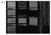
- FIG. 11 shows the results of the elemental analysis of the portion shown in FIG. 10 .
- the upper left picture in FIG. 11 is an image observed by SEM.
- the primary particles contained in the positive electrode mixture layer partially indent the conductive layer.
Landscapes
- Chemical & Material Sciences (AREA)
- Electrochemistry (AREA)
- General Chemical & Material Sciences (AREA)
- Chemical Kinetics & Catalysis (AREA)
- Engineering & Computer Science (AREA)
- Materials Engineering (AREA)
- Manufacturing & Machinery (AREA)
- Composite Materials (AREA)
- Inorganic Chemistry (AREA)
- Crystallography & Structural Chemistry (AREA)
- Battery Electrode And Active Subsutance (AREA)
- Cell Electrode Carriers And Collectors (AREA)
- Secondary Cells (AREA)
Abstract
Description
- The present invention relates to an electric storage device and a method for producing the electric storage device.
- As an electric storage device, nonaqueous electrolyte secondary battery cells such as a lithium ion secondary battery cell are conventionally known. Further, as such a nonaqueous electrolyte secondary battery cell, a battery cell including an electrode group as an electrode assembly and a case housing the electrode group that includes electrode plates respectively having positive and negative polarities is known in general.
- Specifically, the electrode group has a positive electrode plate and a negative electrode plate as the electrode plates, the positive electrode plate includes a positive electrode current collector and a positive electrode active material supported on the positive electrode current collector, and the negative electrode plate includes a negative electrode current collector and a negative electrode active material supported on the negative electrode current collector. Further, the electrode group is formed by layering the positive electrode plate, the negative electrode plate, and a separator interposed between the positive electrode plate and the negative electrode plate together. Furthermore, an electrolyte solution is injected in the case.
- As a known electrode plate, there can be mentioned, for example, those formed by compressing, in the thickness direction, a stack of a current collector and a mixture layer containing a binder and secondary particles each having a hollow region formed therein by aggregation of a plurality of primary particles (fine particles of several µm) of an active material (see
JP 2009-283354 A JP 2011-119092 A - The secondary particles with such a hollow structure contained in the mixture layer enhance the penetration of the electrolyte solution into the hollow regions of the secondary particles. This improves the ion conductance of the mixture layer, thereby allowing an electrode plate with an improved conductivity to be obtained. Further, such compression as mentioned above brings the current collector and the active material in the mixture layer to close contact with each other. As a result, an increase in resistance due to the above-mentioned hollow regions is suppressed.
- In the mixture layer compressed as mentioned above, there are cases where the above-mentioned secondary particles after the compression deforms to return to the shape before the compression because of a time-dependent change in shape of the secondary particles or expansion and contraction of the secondary particles due to repeated charge and discharge. That is, a phenomenon (spring-back) in which the secondary particles after the compression cannot maintain their shape occurs in some cases. When such spring-back occurs, the contact between the current collector and the mixture layer is made loose, which may possibly result in an increase in resistance of the electrode plate.
- In view of the above-mentioned problem, it is an object of the present invention to provide an electric storage device in which the increase in resistance is sufficiently suppressed and a method for producing the electric storage device.
- An electric storage device according to the present invention includes: a first electrode plate; a second electrode plate having a polarity opposite to that of the first electrode plate; and a separator interposed between the first electrode plate and the second electrode plate, wherein the first electrode plate includes a current collector, a conductive layer laminated onto the current collector, and a mixture layer laminated onto the conductive layer, the mixture layer contains a binder and primary particles of an active material as its constituents, and the primary particles as a constituent of the mixture layer are partially retained in the conductive layer.
-
-
FIG. 1 is a schematic perspective view showing a nonaqueous electrolyte secondary battery cell according to one embodiment of the present invention. -
FIG. 2 is a schematic perspective view showing an electrode assembly included in the nonaqueous electrolyte secondary battery cell of this embodiment. -
FIG. 3 is a schematic sectional view schematically showing a layer structure of a positive electrode plate of this embodiment. -
FIG. 4 is a schematic sectional view schematically showing a secondary particle of a positive electrode active material used for the positive electrode plate of this embodiment. -
FIG. 5 is a graph showing a relationship between the number of charge and discharge cycles and the resistance ratio of each test battery cell. -
FIG. 6 is a picture of a cross section in the thickness direction of a positive electrode plate observed by SEM. -
FIG. 7 is a picture of the cross section in the thickness direction of the positive electrode plate observed by SEM. -
FIG. 8 is a picture of the cross section in the thickness direction of the positive electrode plate observed by SEM. -
FIG. 9 is a picture of a cross section in the thickness direction of the positive electrode plate observed by SEM. -
FIG. 10 is a picture showing a portion subjected to elemental analysis. -
FIG. 11 is a picture showing the results of elemental analysis. - An electric storage device according to one embodiment of the present invention includes: a first electrode plate; a second electrode plate having a polarity opposite to that of the first electrode plate; and a separator interposed between the first electrode plate and the second electrode plate, wherein the first electrode plate includes a current collector, a conductive layer laminated onto the current collector, and a mixture layer laminated onto the conductive layer, the mixture layer contains a binder and primary particles of an active material as its constituents, and the primary particles as a constituent of the mixture layer are partially retained in the conductive layer.
- According to such a configuration, the primary particles as a constituent of the mixture layer are partially retained in the conductive layer in the first electrode plate, thereby bringing the mixture layer and the conductive layer into comparatively close contact with each other. Moreover, the contact between the conductive layer and the current collecting layer provides a sufficient conductivity between the conductive layer and the current collecting layer.
- Accordingly, an electric storage device in which the increase in resistance is sufficiently suppressed can be obtained.
- According to one aspect of the electric storage device of this embodiment, the mixture layer further contains secondary particles each having a hollow region formed therein by aggregation of a plurality of the primary particles.
- Here, the phrase "having a hollow region formed therein" means not only having therein a hollow region covered by aggregated primary particles but also having therein a hollow region that is partially uncovered by the primary particles. In other words, the hollow region is a region unfilled with the primary particles.
- According to another aspect of the electric storage device of this embodiment, the active material contained in the mixture layer is lithium iron phosphate.
- According to another aspect of the electric storage device of this embodiment, the primary particles have an average particle size of 100 to 500 nm.
- According to another aspect of the electric storage device of this embodiment, a laminated product of the current collector, the conductive layer, and the mixture layer is compressed in the thickness direction by a compressive force of 50 to 500 kgf/cm.
- According to another aspect of the electric storage device of this embodiment, the conductive layer contains carbon black.
- According to another aspect of the electric storage device of this embodiment, the conductive layer has a thickness of 0.1 to 3.0 µm.
- Hereinafter, an electric storage device of this embodiment is described with reference to the drawings by way of example in which the electric storage device is a nonaqueous electrolyte secondary battery cell.
- As shown in
FIG. 1 andFIG. 2 , a nonaqueous electrolytesecondary battery cell 1 as an electric storage device according to this embodiment includes a case 2, anelectrode assembly 10 as an electrode group housed in the case 2, and anelectrolyte solution 20 as an electrolyte housed in the case 2. Theelectrode assembly 10 includes apositive electrode plate 11 as a first electrode plate, anegative electrode plate 13 as a second electrode plate having a polarity opposite to that of thepositive electrode plate 11, and aseparator 15 interposed between these electrode plates. Theelectrode assembly 10 is formed by layering these components together. - The case 2 includes a box-
shaped case body 3 housing theelectrode assembly 10 and formed with an opening, and a rectangular cover 4 covering the opening of thecase body 3. Thecase body 3 and the cover 4 are formed, for example, of stainless steel plates, and welded to each other. - Two
outer gaskets 5 made of an insulating material are mounted on the outer surface of the cover 4. The cover 4 is formed with two openings. Each of theouter gaskets 5 has one opening. One of the openings of the cover 4 and the opening of one of theouter gaskets 5 are continuous to each other. Likewise, the other of the openings of the cover 4 and the opening of the other of theouter gaskets 5 are continuous to each other. Theouter gaskets 5 each houses anexternal terminal 21 thereinside. - The
external terminal 21 projects inwardly of thecase body 3 through the opening of the correspondingouter gasket 5 and the opening of the cover 4. The projecting portion of theexternal terminal 21 is connected to a current collector connected to thepositive electrode plate 11 or thenegative electrode plate 13 of theelectrode assembly 10. - The current collector, for example, has a plate shape, which however is not particularly restrictive. The current collector is formed of the same metal material as the corresponding electrode member to be connected thereto. The
external terminal 21 is formed of aluminum or aluminum alloy materials such as aluminum alloy, for example. - A set of the
outer gasket 5 and theexternal terminal 21 is provided for each of the positive electrode and the negative electrode. Theouter gasket 5 and theexternal terminal 21 for the positive electrode are arranged on one end side in the longitudinal direction of the cover 4. Theouter gasket 5 and theexternal terminal 21 for the negative electrode are arranged on the other end side in the longitudinal direction of the cover 4. - The cover 4 has an
inlet 6 through which theelectrolyte solution 20 is injected into thecase body 3. Theinlet 6 is sealed after the injection of theelectrolyte solution 20. - The
electrode assembly 10 is housed in thecase body 3. In thecase body 3, oneelectrode assembly 10 may be housed, or a plurality ofelectrode assemblies 10 may be housed. In the latter case, the plurality ofelectrode assemblies 10 are connected electrically in parallel to one another. - The
positive electrode plate 11 includes a positive electrodecurrent collector 11a, aconductive layer 11c laminated onto the positive electrodecurrent collector 11a, and a positiveelectrode mixture layer 11b laminated onto theconductive layer 11c. - The
positive electrode plate 11 is described later in detail. - The
negative electrode plate 13 is formed by disposing a negativeelectrode mixture layer 13b on a negative electrodecurrent collector 13a such as copper foil. Specifically, thenegative electrode plate 13 includes the negative electrodecurrent collector 13a, and the negativeelectrode mixture layer 13b in the form of a layer containing a negative electrode active material. Thenegative electrode plate 13 is formed by laminating the negativeelectrode mixture layer 13b onto the negative electrodecurrent collector 13a. - Examples of the negative electrode active material contained in the negative
electrode mixture layer 13b include carbon materials such as amorphous carbon, non-graphitizable carbon, graphitizable carbon, and graphite. - The negative
electrode mixture layer 13b may contain a binder such as polyvinylidene fluoride (PVDF), and a conductive additive such as acetylene black, etc., in addition to the above-mentioned negative electrode active material. - The thickness of the negative
electrode mixture layer 13b is generally, though not particularly restricted to, about 20 µm to 200 µm. - The
separator 15 allows theelectrolyte solution 20 to permeate therethrough while blocking electrical connection between thepositive electrode plate 11 and thenegative electrode plate 13. Examples of theseparator 15 include a porous film formed of polyolefin resins such as polyethylene. Such a porous film may contain additives such as a plasticizer, an antioxidant, and a flame retardant. - The
electrolyte solution 20 is prepared by dissolving an electrolyte salt in an organic solvent. - The organic solvent used for the
electrolyte solution 20 is not particularly limited. Examples thereof include ethers, ketones, lactones, nitriles, amines, amides, sulfur compounds, hydrocarbon halides, esters, carbonates, nitro compounds, phosphate ester compounds, and sulfolane hydrocarbons. - Among these, ethers, ketones, esters, lactones, hydrocarbon halides, carbonates, or sulfolane compounds are preferable.
- Examples thereof include tetrahydrofuran, 2-methyltetrahydrofuran, 1,4-dioxane, anisole, monoglyme, 4-methyl-2-pentanone, ethyl acetate, methyl acetate, methyl propionate, ethyl propionate, 1,2-dichloroethane, γ-butyrolactone, dimethoxyethane, methyl formate, dimethyl carbonate, methylethyl carbonate, diethyl carbonate, propylene carbonate, ethylene carbonate, vinylene carbonate, dimethylformamide, dimethylsulfoxide, dimethylthioformamide, sulfolane, 3-methyl-sulfolane, trimethyl phosphate, and triethyl phosphate, and a mixed solvent of them.
- The organic solvent is preferably cyclic carbonates or cyclic esters. The organic solvent is most preferably one or a mixture of two or more of ethylene carbonate, propylene carbonate, methylethyl carbonate, and diethyl carbonate.
- Further, the electrolyte salt used for the
electrolyte solution 20 is not particularly limited. However, examples thereof include LiClO4, LiBF4, LiAsF6, CF3SO3Li, LiPF6, LiN(CF3SO2)2, LiN(C2F5SO2)2, LiI, and LiAlCl4, and a mixture of them. - The electrolyte salt is preferably one or a mixture of two or more of lithium salt selected from LiBF4 and LiPF6.
- It should be noted that the
electrolyte solution 20 is not specifically limited to an electrolyte solution containing such an organic solvent and electrolyte salt as mentioned above. - Other than above, a film formed of a solid ion conducting material (solid electrolyte film) can be further used complementarily as the electrolyte. In the case of using such a film, the nonaqueous electrolyte
secondary battery cell 1 can be formed of thepositive electrode plate 11, thenegative electrode plate 13, theseparator 15 and the solid electrolyte film disposed between these electrode plates, and theelectrolyte solution 20. Alternatively, the nonaqueous electrolytesecondary battery cell 1 can be formed of thepositive electrode plate 11, thenegative electrode plate 13, the solid electrolyte film disposed between these electrode plates, and theelectrolyte solution 20. - Further, it is advantageous that the solid electrolyte film be an organic solid electrolyte formed of polyethylene oxide, polyacrylonitrile, or polyethylene glycol, or a modified product of them, when winding the solid electrolyte film, because of the lightweight and flexibility of the organic solid electrolyte. Other than above, the solid electrolyte film can be formed using an inorganic solid electrolyte, or a mixed material of an organic solid electrolyte and an inorganic solid electrolyte.
- The
positive electrode plate 11 of this embodiment includes the positive electrodecurrent collector 11a, theconductive layer 11c laminated onto the positive electrodecurrent collector 11a, and the positiveelectrode mixture layer 11b laminated onto theconductive layer 11c. Further, the positiveelectrode mixture layer 11b contains abinder 22 and positive electrode active material particles 23, and the positive electrode active material particles 23 containsprimary particles 24 of a positive electrode active material and secondary particles 25 (secondary particle spheres) each having a hollow region R (seeFIG. 4 ) formed therein by aggregation of a plurality of theprimary particles 24. - As the positive electrode
current collector 11a, an aluminum foil can be mentioned, for example. The thickness of the positive electrodecurrent collector 11a is generally about 10 to 30 µm. - As shown in
FIG. 3 , the positiveelectrode mixture layer 11b contains thebinder 22, theprimary particles 24 of a positive electrode active material, and the secondary particles 25 (seeFIG. 4 ) each having the hollow region R formed therein by aggregation of a plurality of theprimary particles 24. In other words, the positiveelectrode mixture layer 11b contains thebinder 22 and theprimary particles 24 of the positive electrode active material. In the positiveelectrode mixture layer 11b, a plurality of theprimary particles 24 partially aggregate so as to form secondary particle spheres each having the hollow region R. - Examples of the
binder 22 include polyvinylidene fluoride (PVDF). - Examples of the positive electrode active material include lithium iron phosphate represented by LiFePO4, LiMnPO4, and Li3V2(PO4)3.
- The
primary particles 24 of the positive electrode active material have an average particle size, for example, of 100 to 500 nm. The average particle size thereof can be measured by SEM observation. - Further, the
secondary particles 25 each having the hollow region R formed therein by aggregation of theprimary particles 24 is produced, for example, by spray drying. Specifically, a mixed solution, for example, of lithium hydroxide monohydrate (LiOH•H2O) as a lithium source, iron sulfate heptahydrate (FeSO4•7H2O) as an iron source, and phosphoric acid (H3PO4) as a phosphate source is prepared. The thus prepared mixed solution is spray-dried using a spray dryer. As a spray drying apparatus, a spray dryer (manufactured by Ohkawara Kakohki Co., Ltd.), for example, is used. In spray drying, for example, a mixture of the mixed solution and the air is sprayed into the spray dryer through a binary fluid nozzle, followed by drying, with the drying temperature at the inlet of the spray dryer set to 140°C and the drying temperature at the outlet thereof set to 110°C, which is thereafter sintered at 700°C for 5 hours under nitrogen airflow. This allows lithium iron phosphate to be synthesized so as to form theprimary particles 24 of lithium iron phosphate, and theprimary particles 24 of lithium iron phosphate aggregate, thereby producing thesecondary particles 25 each having the hollow region R thereinside. - It should be noted that the shape of each
secondary particle 25 is not specifically limited, as long as having the hollow region R into which theelectrolyte solution 20 can penetrate. Further, the hollow region R formed inside thesecondary particle 25 may be covered by aggregates of theprimary particles 24, or may be partially not covered by them. - The above-mentioned secondary particles 25 (secondary particle spheres 25) have an average particle size, for example, of 5 to 20 µm. The average particle size thereof can be determined using a laser diffraction particle size distribution analyzer (manufactured by SHIMADZU CORPORATION).
- Further, the
primary particles 24 as a constituent of the positiveelectrode mixture layer 11b are partially distributed and retained in theconductive layer 11c. - That is, the positive
electrode mixture layer 11b is formed with theprimary particles 24 contained in the positiveelectrode mixture layer 11b partially indenting theconductive layer 11c. Specifically, the positiveelectrode mixture layer 11b is formed by compression in the thickness direction of a layered stack of the positive electrodecurrent collector 11a, theconductive layer 11c, and the positiveelectrode mixture layer 11b, as described later. This allows theprimary particles 24 contained in the positiveelectrode mixture layer 11b to indent theconductive layer 11c. - Since the
primary particles 24 of the positiveelectrode mixture layer 11b partially indent theconductive layer 11c, the contact between the positiveelectrode mixture layer 11b and theconductive layer 11c is less likely to be impaired even when the spring-back is caused by the time-dependent change after the compression or the expansion and contraction due to charge and discharge. That is, theprimary particles 24 that have indented theconductive layer 11c function as an anchor. In this way, the positiveelectrode mixture layer 11b and theconductive layer 11c are stacked together, with theprimary particles 24 that function as an anchor being interposed therebetween. - Further, the positive
electrode mixture layer 11b may contain secondary particles that have partially lost their hollow regions R because of breakage of thesecondary particles 25 by compression, which will be described later. - The positive
electrode mixture layer 11b may contain other components such as a conductive additive, in addition to the binder and the positive electrode active material particles 23. Examples of the conductive additive include carbon black and acetylene black. - The thickness of the positive
electrode mixture layer 11b is generally, though not particularly restricted to, about 20 µm to 200 µm. Further, the content ratio of theprimary particles 24 to thesecondary particles 25 in the positive electrode active material particles 23 is not specifically limited, and may be appropriately set depending on the required degree of suppression of the increase in resistance. - The
conductive layer 11c is softer than the positive electrodecurrent collector 11a. - Here, the phrase "the
conductive layer 11c is softer than the positive electrodecurrent collector 11a" means that Vickers hardness (Hv) of theconductive layer 11c is lower than Vickers hardness of the positive electrodecurrent collector 11a. - Vickers hardness is a value obtained by dividing the load when a pyramidal recess is formed on a surface of a specimen using a diamond indenter in the form of a square pyramid with an angle of 136° between opposite faces by the diagonal length of the recess (as measured by a method in accordance with JIS Z2244).
- The Vickers hardness of the
conductive layer 11c is not particularly limited, as long as it is lower than Vickers hardness of the positive electrodecurrent collector 11a. - As the difference in Vickers hardness between the
conductive layer 11c and the positive electrodecurrent collector 11a, expressed as [(Vickers hardness of the positive electrodecurrent collector 11a) - (Vickers hardness of theconductive layer 11c)], increases, it is easier for thesecondary particles 25 in the positiveelectrode mixture layer 11b to indent (dig) theconductive layer 11c. Thus, there is a tendency that theconductive layer 11c and the positiveelectrode mixture layer 11b are brought into firmer contact with each other. - Meanwhile, if the above-mentioned difference in Vickers hardness is excessively high, Vickers hardness of the
conductive layer 11c is excessively low, which may possibly weaken the strength of theconductive layer 11c. Further, Vickers hardness of the positive electrodecurrent collector 11a is excessively high, which may possibly make it difficult to wind the positive electrodecurrent collector 11a. - Accordingly, the above-mentioned difference, for example, is preferably at least 5 but not more than 35.
- Further, Vickers hardness of the
conductive layer 11c, for example, is preferably at least 5 but not more than 15. - Further, Vickers hardness of the positive electrode
current collector 11a, for example, is preferably at least 20 but not more than 40. - The thickness of the
conductive layer 11c is preferably 0.1 to 3.0 µm, more preferably 0.1 to 1.0 µm. - The
conductive layer 11c, for example, contains a conductive agent and a binder. The conductive agent is not specifically limited, as long as it is a conductive material that allows theconductive layer 11c formed using the conductive agent to be softer than the positive electrodecurrent collector 11a. - It should be noted that Vickers hardness of the
conductive layer 11c can be appropriately adjusted by changing the kind or amount of the conductive agent to be added. In consideration of such viewpoints, preferable examples of the conductive agent include carbon black, acetylene black, and Ketjen black. Further, the amount of the conductive agent to be added is preferably 10 to 90 mass% with respect to the total mass of theconductive layer 11c. - Further, the binder is not specifically limited, as long as it is a material that is capable of binding the conductive agent to itself, binding the conductive agent to the positive electrode
current collector 11a, and binding the conductive agent to the positiveelectrode mixture layer 11b, and is softer than the positive electrodecurrent collector 11a. - It should be noted that Vickers hardness of the
conductive layer 11c can be appropriately adjusted by changing the kind or content amount of the binder. In consideration of such viewpoints, examples of the binder include polyvinylidene fluoride, polyethylene oxide, and chitosan. Further, the content amount of the binder is preferably 10 to 90 mass% with respect to the total mass of theconductive layer 11c. - Further, the
conductive layer 11c may contain other components in addition to the conductive agent and the binder. However, such other components may possibly affect Vickers hardness of theconductive layer 11c. Accordingly, the kind and content amount of such other components can be appropriately set in consideration of such viewpoints. - As has been described above, the
positive electrode plate 11 of this embodiment includes theconductive layer 11c and the positiveelectrode mixture layer 11b containing theprimary particles 24 of a positive electrode active material and thesecondary particles 25 each having the hollow region R formed by aggregation of theprimary particles 24, in which theprimary particles 24 of the positiveelectrode mixture layer 11b are partially retained in theconductive layer 11c. - When the
primary particles 24 contained in the positiveelectrode mixture layer 11b are partially retained in theconductive layer 11c, as mentioned above, the positiveelectrode mixture layer 11b and theconductive layer 11c are brought into comparatively close contact with each other. Further, even if thesecondary particles 25 undergo time-dependent changes or expansion and contraction due to repeated charge and discharge, the contact between the positiveelectrode mixture layer 11b and theconductive layer 11c is suppressed from being made loose. Moreover, the aforementioned anchor function allows a sufficient conductivity to be maintained between the positiveelectrode mixture layer 11b and theconductive layer 11c. - Meanwhile, the conductivity between the
conductive layer 11c and the positive electrodecurrent collector 11a is also maintained sufficient. - Accordingly, the
positive electrode plate 11 in which the increase in resistance is more sufficiently suppressed can be obtained. - Further, in the
positive electrode plate 11 according to this embodiment, theconductive layer 11c is softer than the positive electrodecurrent collector 11a. - This facilitates indentation of the
primary particles 24 contained in the positiveelectrode mixture layer 11b into theconductive layer 11c when thepositive electrode plate 11 is formed by compressing a layered stack of the positive electrodecurrent collector 11a, theconductive layer 11c, and the positiveelectrode mixture layer 11b in the thickness direction. Accordingly, the contact between the positiveelectrode mixture layer 11b and theconductive layer 11c is made closer than the contact between the positiveelectrode mixture layer 11b and the positive electrodecurrent collector 11a. Thus, thepositive electrode plate 11 in which the increase in resistance is further sufficiently suppressed can be obtained. - Further, the
positive electrode plate 11 of this embodiment is formed so that theprimary particles 24 of the positiveelectrode mixture layer 11b partially indent theconductive layer 11c, by compression in the thickness direction of a layered stack of the positive electrodecurrent collector 11a, theconductive layer 11c, and the positiveelectrode mixture layer 11b. In this way, the positiveelectrode mixture layer 11b indents theconductive layer 11c, thereby bringing the positiveelectrode mixture layer 11b and theconductive layer 11c into closer contact with each other. Therefore, thepositive electrode plate 11 in which the increase in resistance is further sufficiently suppressed can be obtained. - Further, the nonaqueous electrolyte
secondary battery 1 of this embodiment includes the above-describedpositive electrode plate 11, and thus the increase in resistance is suppressed therein. - Subsequently, a method for producing an electric storage device (nonaqueous electrolyte secondary battery 1) of this embodiment is described. That is, such a production method includes: an electrode plate producing step of producing electrode plates; and a layering step of layering a first electrode plate and a second electrode plate having a polarity opposite to that of the first electrode plate with a separator interposed therebetween, the electrode plates being produced in the electrode plate producing step, wherein the electrode plate producing step includes: a step of laminating a conductive layer onto a current collector; a step of laminating a mixture layer containing a binder and primary particles of an active material onto the conductive layer; and a step of compressing, in the thickness direction, a laminated product of the current collector, the conductive layer, and the mixture layer.
- According to such a configuration, the first electrode plate is formed by compressing a laminated product of the current collector, the conductive layer, and the mixture layer, thereby allowing the primary particles of the mixture layer to be partially retained in the conductive layer. This brings the mixture layer and the conductive layer into comparatively close contact with each other. Moreover, the conductivity between the conductive layer and the current collector is maintained sufficient by the contact between the conductive layer and the current collector.
- Accordingly, an electric storage device in which the increase in resistance is sufficiently suppressed can be obtained.
- According to one aspect of a method for producing an electric storage device of this embodiment, the mixture layer laminated onto the conductive layer in the step of laminating the mixture layer of the electrode plate producing step further contains secondary particles each having a hollow region formed therein by aggregation of a plurality of the primary particles.
- Specifically, the method for producing the nonaqueous electrolyte
secondary battery 1 of this embodiment includes a positive electrode plate producing step of producing thepositive electrode plate 11 as the electrode plate producing step. - Further, this production method includes the layering step of layering the
positive electrode plate 11 as a first electrode plate, which is produced in the positive electrode plate producing step, and thenegative electrode plate 13 as a second electrode plate with aseparator 15 interposed therebetween. - First, the positive electrode plate producing step is described.
- The positive electrode plate producing step includes: a step of laminating the
conductive layer 11c that is softer than the positive electrodecurrent collector 11a onto the positive electrodecurrent collector 11a (first lamination step); a step of laminating, onto theconductive layer 11c, the positiveelectrode mixture layer 11b containing thebinder 22, theprimary particles 24 of a positive electrode active material, and thesecondary particles 25 each having the hollow region R formed thereinside by aggregation of a plurality of the primary particles 24 (second lamination step); and a step of compressing, in the thickness direction, a layered stack of the positive electrodecurrent collector 11a, theconductive layer 11c, and the positiveelectrode mixture layer 11b (compression step). - Specifically, in the positive electrode plate producing step, a conductive agent, a binder, and an organic solvent such as N-methylpyrrolidone are first mixed, so that a mixture in paste form (conductive layer mixture paste) is prepared. This mixture is applied onto the positive electrode
current collector 11a, followed by drying, thereby forming theconductive layer 11c on the positive electrodecurrent collector 11a (first lamination step). - Next, positive electrode active material particles containing the
primary particles 24 and thesecondary particles 25, a binder, a conductive additive or the like, and an organic solvent such as N-methylpyrrolidone are mixed, so that a mixture in paste form (positive electrode mixture paste) is prepared. This mixture is applied onto the above formedconductive layer 11c, followed by drying, thereby allowing the positiveelectrode mixture layer 11b to be laminated onto theconductive layer 11c (second lamination step). - Then, the resultant laminated product is compressed using a roll press or the like (compression step).
- In this way, the
positive electrode plate 11 is produced. - In the positive electrode plate producing step, a conventionally known mixing apparatus is used for preparing the conductive layer mixture paste or the positive electrode mixture paste. Further, a conventionally known coating apparatus and drying apparatus are used for forming the
conductive layer 11c or the positiveelectrode mixture layer 11b. - In the compression step, if the compressive force for compressing the layered stack is excessively small, it is difficult to allow the
secondary particles 25 to sufficiently indent theconductive layer 11c. On the other hand, if the compressive force for compressing the layered stack is excessively large, thesecondary particles 25 are crushed, which excessively reduces the hollow regions R of thesecondary particles 25 in the positiveelectrode mixture layer 11b. As a result, there is a possibility that sufficient penetration of theelectrolyte solution 20 into the positiveelectrode mixture layer 11b is made difficult. - Accordingly, the compressive force is appropriately set, for example, in consideration of such viewpoints. The compressive force, for example, is preferably set to 50 to 500 kgf/cm.
- According to the above-mentioned production method of this embodiment, the
positive electrode plate 11 in which the positiveelectrode mixture layer 11b and theconductive layer 11c are in comparatively close contact with each other as above is produced. Further, thepositive electrode plate 11 in which the contact between the positiveelectrode mixture layer 11b and theconductive layer 11c is closer than the contact between theconductive layer 11c and the positive electrodecurrent collector 11a is produced. Further, thepositive electrode plate 11 in which the contact between the positiveelectrode mixture layer 11b and theconductive layer 11c is suppressed from being made loose, even when thesecondary particles 25 undergo time-dependent changes, or expansion and contraction due to repeated charge and discharge is produced. Moreover, the contact between theconductive layer 11c and the positive electrodecurrent collector 11a maintains a sufficient conductivity therebetween. Accordingly, thepositive electrode plate 11 in which the increase in resistance is sufficiently suppressed can be obtained. - Subsequently, a negative electrode plate is produced. In producing the negative electrode plate, a negative electrode active material, a binder, a conductive additive or the like, and an organic solvent are mixed, so that a mixture in paste form (negative electrode mixture paste) is obtained. This mixture is applied onto the negative electrode
current collector 13a, followed by drying. Thereafter, the resultant laminated product is compressed using a roll press or the like. Thus, thenegative electrode plate 13 is produced. - Next, a step of layering the
positive electrode plate 11 and thenegative electrode plate 13 with theseparator 15 interposed therebetween is described. - Specifically, the
positive electrode plate 11 and thenegative electrode plate 13 produced as above, and theseparator 15 are first prepared. - Next, the
positive electrode plate 11, theseparator 15, thenegative electrode plate 13, and theseparator 15 are disposed in this order and stacked together. - Thereafter, the stack is wound, thereby forming the
electrode assembly 10. Subsequently, theelectrode assembly 10 is inserted into thecontainer body 3. Further, current collectors are connected respectively to thepositive electrode plate 11 and thenegative electrode plate 13. Then, the opening of thecontainer body 3 is covered by the cover 4 with theouter gaskets 5 and theexternal terminals 21 mounted thereon, and the current collectors are connected respectively to theexternal terminals 21. In this state, thecontainer body 3 and the cover 4 are welded to each other. Further, theelectrolyte solution 20 is injected into the container 2 through theinlet 6. Finally, theinlet 6 is closed, so that a nonaqueous electrolyte secondary battery cell is produced. - According to the above-mentioned method for producing the nonaqueous electrolyte
secondary battery 1 of this embodiment, the nonaqueous electrolytesecondary battery 1 including the above-mentionedpositive electrode plate 11 is produced. Therefore, the nonaqueous electrolytesecondary battery 1 in which the resistance is sufficiently suppressed can be obtained. - It should be noted that the method for producing the nonaqueous electrolyte
secondary battery 1 of this embodiment is not particularly limited to the production method exemplified above. - As has been described above, the electric storage device and the method for producing the electric storage device according to this embodiment provide an electric storage device in which the increase in resistance is sufficiently suppressed and a method for producing such an electric storage device.
- Although the electrode plate, the battery cell, and the method for producing these according to the present invention are as mentioned above, the present invention is not limited to the embodiments mentioned above. The design can be appropriately modified within the scope intended by the present invention.
- For example, the present invention may have a configuration in which the
binder 22 and the above-mentioned conductive additive or the like mentioned above are partially distributed in the hollow regions R in the positiveelectrode mixture layer 11b. Further, a configuration in which thenegative electrode plate 13 has a conductive layer between the negative electrodecurrent collector 13a and the negativeelectrode mixture layer 13b, and the negative electrode mixture layer - 13b contains secondary particles each having the hollow region R formed thereinside by aggregation of primary particles of a negative electrode active material may be employed.
- The battery cell of the present invention is suitable as a nonaqueous electrolyte secondary battery cell, particularly, a lithium ion secondary battery cell, and is further suitable as a large battery cell. However, the battery cell of the present invention is not particularly limited to these.
- Further, the present invention is not limited also to those having the actions and effects of the above-mentioned embodiments.
- Although the electric storage device and the method for producing the electric storage device according to the aforementioned embodiments are as mentioned above, the present invention is not limited to the embodiments mentioned above as an example. The design can be appropriately modified within the scope intended by the present invention. The operational advantage of the present invention is also not limited to the foregoing embodiments.
- The embodiments disclosed herein should be construed in all respects as illustrative but not limiting. The scope of the present invention is not indicated by the foregoing description but by the scope of the claims. Further, the scope of the present invention is intended to include all the modifications equivalent in the sense and the scope to the scope of the claims.
- Next, the present invention is described further in detail by way of examples. However, the present invention is not limited to these examples.
- A mixed solution of lithium hydroxide monohydrate (LiOH•H2O) as a lithium source, iron sulfate heptahydrate (FeSO4•7H2O) as an iron source, phosphoric acid (H3PO4) as a phosphate source at a molar ratio of 1:1:1 was prepared.
- The mixed solution prepared above was spray-dried using a spray dryer (manufactured by Ohkawara Kakohki Co., Ltd.). In spray drying, a mixture of the mixed solution and the air was sprayed into the spray dryer through a binary fluid nozzle so as to be dried at a drying temperature at the inlet of 140°C and a drying temperature at the outlet of 110°C. After the drying, the dried product was sintered at 700°C for 5 hours under nitrogen airflow. In this way, lithium iron phosphate as a positive electrode active material was synthesized, and primary particles of lithium iron phosphate aggregate, thereby producing secondary particles each having a hollow region thereinside. The average particle size of the thus produced secondary particles was measured using a laser diffraction particle size distribution analyzer (manufactured by SHIMADZU CORPORATION). As a result, their average particle size was 10 µm (in all the following experiments, the same method was employed for measuring average particle sizes).
- A mixed solution of lithium hydroxide monohydrate (LiOH•H2O) as a lithium source, iron sulfate heptahydrate (FeSO4•7H2O) as an iron source, and diammonium hydrogenphosphate (NH4H2PO4) as a phosphate source was further mixed well in a mortar. Thereafter, the resultant product was calcined at 300°C for 3 hours under nitrogen airflow. The resultant calcined product was pulverized to obtain smaller pellets, which thereafter were sintered at 300°C for 3 hours in the air. In this way, non-hollow solid lithium phosphate particles were obtained. The thus produced secondary particles had an average particle size of 10 µm.
- First, 50 mass% of carbon black as a conductive agent and 50 mass% of PVDF were mixed. To this mixture was added N-methylpyrrolidone as a solvent. Thus, a conductive agent mixture paste was prepared. The conductive layer mixture paste was applied to each of both sides of an aluminum foil with a thickness of 20 µm as a positive electrode current collector so as to form a conductive layer of 0.02 g/100 cm2. It was further dried, and thus a conductive layer was formed.
- Meanwhile, 80 mass% of positive electrode active material particles including the above produced secondary particles of the positive electrode active material each having a hollow region or 80 mass% of positive electrode active material particles including the above produced solid secondary particles of the positive electrode active material, 10 mass% of acetylene black as a conductive additive, and 10 mass% of PVDF were mixed. To this mixture was added N-methylpyrrolidone as a solvent. Thus, a positive electrode mixture paste was prepared. The positive electrode mixture paste was applied to each of both sides of an aluminum foil with a thickness of 10 µm as a positive electrode current collector so as to form a positive electrode mixture layer of 1.5 g/100 cm2. It was further dried, and thus the positive electrode mixture layer was formed on a conductive layer.
- Thereafter, the above produced layered stacks were each subjected to compression molding with a load of 100 kgf/cm using a roll press. Thus, strip-shaped positive electrode plates were produced. Each positive electrode member had a length of 500 cm, a width of 10 cm, and a thickness of 180 µm in total of each positive electrode current collector, and the conductive layers or the positive electrode mixture layers on both sides of the positive electrode current collector.
- Vickers hardness of the positive electrode current collector and the conductive layer in each
positive electrode plate 11 was measured, using a dynamic ultra micro hardness tester (DUH-211S, manufactured by SHIMADZU CORPORATION) which functions as a Vickers hardness meter, under specific conditions according to JIS Z2244. They respectively had a hardness of 30 and 10. - A positive electrode plate was produced in the same manner as above except that the above-mentioned conductive layer was not formed. That is, a positive electrode mixture paste containing secondary particles, each having a hollow region, of a positive electrode active material, or alternatively, a positive electrode mixture paste containing solid secondary particles of the positive electrode active material was applied onto each of both surfaces of an aluminum foil as a positive electrode current collector so as to form a positive electrode mixture layer of 1.5 g/100 cm2. It was further dried, and thus a positive electrode mixture layer was formed. Thereafter, the positive electrode mixture layer was subjected to compression molding with a load of 100 kgf/cm using a roll press. Thus, each positive electrode plate in the form of a strip was produced. The positive electrode member had a length of 500 cm, a width of 10 cm, and a thickness of 175 µm in total of the positive electrode current collector and the positive electrode mixture layers on both sides thereof.
- 90 mass% of a negative electrode active material, 2 mass% of acetylene black as a conductive additive, and 8 mass% of PVDF were mixed. To this mixture was added N-methylpyrrolidone as a solvent. Thus, a negative electrode mixture paste was prepared. The negative electrode mixture paste was applied to each of both sides of a copper foil as a negative electrode current collector having a thickness of 10 µm so as to form a negative electrode mixture layer of 0.8 g/100 cm2. It was further dried, and thus the negative electrode mixture layer was formed. Thereafter, the above produced layered stack was subjected to compression molding with a load of 100 kgf/cm using a roll press. Thus, a strip-shaped negative electrode plate was produced. The negative electrode member had a length of 500 cm, a width of 10 cm, and a thickness of 120 µm in total of the negative electrode current collector, and the negative electrode mixture layers on both sides of the negative electrode current collector.
- A positive electrode tab and a negative electrode tab were attached respectively to the positive electrode plate and the negative electrode plate produced as above.
- Further, a microporous polyolefin film having a width of 12 cm and a thickness of 25 µm was prepared as a separator.
- Next, the positive electrode plate, a separator, the negative electrode plate, and a separator were disposed in layers in this order, which were further wound into an elongated cylindrical shape. Thus, an electrode assembly was produced. The electrode assembly was housed in a case body, and a cover was mounted on the case. Furthermore, an electrolyte solution was injected into the case. Thus, test battery cells were each produced.
- Using each test battery cell, a capacity retention test was conducted.
- Specifically, the resistance of the battery cell after being charged at a current of 1 CA to a voltage of 4.1 V, followed by being discharged at a current of 1 CA to a voltage of 2.5 V was measured using a impedance meter (manufactured by HIOKI E.E. CORPORATION). The resistance as measured at a frequency of 1 kHz using the AC impedance method was expressed as percentage (%) with the resistance of a cell including a non-hollow solid layer and a conductive layer being defined as 100% (resistance ratio).
- Next, this test battery cell was subjected to 500 cycles of charge and discharge under the same charge and discharge conditions. Thereafter, the resistance thereof was measured in the same manner as above, and the resistance ratio (%) was calculated.
FIG. 5 shows the results. - In
FIG. 5 , the result of a test battery cell in which the positive electrode active material particles are solid particles, and the positive electrode plate has a conductive layer is shown by "white circles ○". Further, the result of a test battery cell in which the positive electrode active material particles are solid particles, and the positive electrode plate has no conductive layer is shown by "black circles ●". Furthermore, the result of a test battery cell in which the positive electrode active material particles are second particles each having a hollow region, and the positive electrode plate has a conductive layer is shown by "white triangles Δ". Moreover, the result of a test battery cell in which the positive electrode active material particles are second particles each having a hollow region, and the positive electrode plate has no conductive layer is shown by "black triangles ▲". - As shown in
FIG. 5 , the test battery cell in which the solid positive electrode active material particles were used was little affected in the increase in resistance at the beginning and during the charge and discharge cycles by the presence or absence of a conductive layer. - On the other hand, the test battery cell, having no conductive layer, in which the positive electrode active material particles containing second particles each having a hollow region were used had a high resistance from the beginning, and the increase in resistance during the charge and discharge cycles also was significant. In contrast, in the case of the test battery cell having a conductive layer, the increase in resistance was remarkably suppressed both at the beginning and during the charge and discharge cycles, as compared to the case of the test battery cell having no conductive layer.
-
FIG. 6 to FIG. 9 each show a picture of a cross section of the positive electrode plate observed by SEM. The magnification was 1,000 times inFIG. 6 ,2 ,000 times inFIG. 7 , and10 ,000 times inFIG. 8 . - A positive electrode plate for the observation was produced in the same manner as above except that the conductive agent mixture paste was applied so as to form a conductive layer of 1.4 g/m2. It should be noted that the positive electrode plate produced for the observation had the conductive layer, and the conductive layer of the positive electrode plate incorporated the secondary particles each having a hollow region formed thereinside as mentioned above.
- Particularly, as seen from
FIG. 8 (indicated by the arrow), the primary particles as a constituent of the mixture layer were partially retained in the conductive layer. That is, the primary particles contained in the positive electrode mixture layer partially indent the conductive layer. - Further, the positive electrode plate produced in the same manner as the positive electrode plate observed by SEM was subjected to elemental analysis using an FE-EPMA (field emission electron probe microanalyzer), "JXA-8500F", manufactured by JEOL Ltd.
FIG. 10 andFIG. 11 show the results. -
FIG. 10 is a picture, observed by SEM, showing a portion subjected to elemental analysis.FIG. 11 shows the results of the elemental analysis of the portion shown inFIG. 10 . The upper left picture inFIG. 11 is an image observed by SEM. - As seen from the analysis results shown in
FIG. 11 , particularly, for Fe and P (the first and second pictures from the bottom on the left side), the primary particles contained in the positive electrode mixture layer partially indent the conductive layer.
Claims (9)
- An electric storage device comprising:a first electrode plate; a second electrode plate having a polarity opposite to that of the first electrode plate; and a separator interposed between the first electrode plate and the second electrode plate, whereinthe first electrode plate includes a current collector, a conductive layer laminated onto the current collector, and a mixture layer laminated onto the conductive layer,the mixture layer contains a binder and primary particles of an active material as its constituents, andthe primary particles as a constituent of the mixture layer are partially retained in the conductive layer.
- The electric storage device according to claim 1, wherein
the mixture layer further contains secondary particles each having a hollow region formed therein by aggregation of a plurality of the primary particles. - The electric storage device according to claim 1 or 2, wherein
the active material contained in the mixture layer is lithium iron phosphate. - The electric storage device according to any one of claims 1 to 3, wherein the primary particles have an average particle size of 100 to 500 nm.
- The electric storage device according to any one of claims 1 to 4, wherein
a laminated product of the current collector, the conductive layer, and the mixture layer is compressed in the thickness direction by a compressive force of 50 to 500 kgf/cm. - The electric storage device according to any one of claims 1 to 5, wherein the conductive layer contains carbon black.
- The electric storage device according to any one of claims 1 to 6, wherein the conductive layer has a thickness of 0.1 to 3.0 µm.
- A method for producing an electric storage device comprising:an electrode plate producing step of producing electrode plates; anda layering step of layering a first electrode plate and a second electrode plate having a polarity opposite to that of the first electrode plate with a separator interposed therebetween, the electrode plates being produced in the electrode plate producing step, whereinthe electrode plate producing step includes:a step of laminating a conductive layer onto a current collector,a step of laminating a mixture layer containing a binder and primary particles of an active material onto the conductive layer, anda step of compressing, in the thickness direction, a laminated product of the current collector, the conductive layer, and the mixture layer.
- The method for producing an electric storage device according to claim 8, wherein
the mixture layer laminated onto the conductive layer in the step of laminating the mixture layer of the electrode plate producing step further contains secondary particles each having a hollow region formed therein by aggregation of a plurality of the primary particles.
Applications Claiming Priority (2)
| Application Number | Priority Date | Filing Date | Title |
|---|---|---|---|
| JP2013004095 | 2013-01-11 | ||
| JP2013261367A JP6361955B2 (en) | 2013-01-11 | 2013-12-18 | Storage element and method for manufacturing the same |
Publications (2)
| Publication Number | Publication Date |
|---|---|
| EP2755261A1 true EP2755261A1 (en) | 2014-07-16 |
| EP2755261B1 EP2755261B1 (en) | 2018-12-12 |
Family
ID=50238094
Family Applications (1)
| Application Number | Title | Priority Date | Filing Date |
|---|---|---|---|
| EP14150706.1A Active EP2755261B1 (en) | 2013-01-11 | 2014-01-10 | Electric storage device and manufacturing method thereof |
Country Status (5)
| Country | Link |
|---|---|
| US (1) | US9954219B2 (en) |
| EP (1) | EP2755261B1 (en) |
| JP (1) | JP6361955B2 (en) |
| KR (1) | KR20140091478A (en) |
| CN (1) | CN103928711B (en) |
Cited By (2)
| Publication number | Priority date | Publication date | Assignee | Title |
|---|---|---|---|---|
| EP3073556A1 (en) * | 2015-03-26 | 2016-09-28 | GS Yuasa International Ltd. | Energy storage device |
| EP3196963A4 (en) * | 2014-08-25 | 2017-07-26 | Nissan Motor Co., Ltd | Electrode |
Families Citing this family (13)
| Publication number | Priority date | Publication date | Assignee | Title |
|---|---|---|---|---|
| JP6361955B2 (en) * | 2013-01-11 | 2018-07-25 | 株式会社Gsユアサ | Storage element and method for manufacturing the same |
| JP6048751B2 (en) * | 2013-06-06 | 2016-12-21 | 株式会社豊田自動織機 | Current collector for lithium ion secondary battery, electrode for lithium ion secondary battery, and lithium ion secondary battery |
| JP6237652B2 (en) * | 2015-01-09 | 2017-11-29 | トヨタ自動車株式会社 | Nonaqueous electrolyte secondary battery electrode and method for producing the same |
| JP6269597B2 (en) | 2015-06-29 | 2018-01-31 | トヨタ自動車株式会社 | Positive electrode active material layer, all solid lithium battery, and method for producing positive electrode active material layer |
| JP6394987B2 (en) * | 2015-08-06 | 2018-09-26 | トヨタ自動車株式会社 | Non-aqueous electrolyte secondary battery |
| JP6947182B2 (en) * | 2016-09-07 | 2021-10-13 | 株式会社Gsユアサ | Power storage element and manufacturing method of power storage element |
| TWI617073B (en) | 2016-11-25 | 2018-03-01 | 財團法人工業技術研究院 | Battery electrode structure and method for fabricating the same |
| JP6834870B2 (en) * | 2017-09-15 | 2021-02-24 | トヨタ自動車株式会社 | Non-aqueous electrolyte secondary battery and its manufacturing method |
| DE102018219988A1 (en) * | 2018-11-22 | 2020-05-28 | Robert Bosch Gmbh | Semi-electrode stack and its manufacture |
| JP7691257B2 (en) * | 2021-03-29 | 2025-06-11 | Tdk株式会社 | Electrode for lithium ion secondary battery and lithium ion secondary battery |
| US20230261207A1 (en) * | 2021-03-31 | 2023-08-17 | Tdk Corporation | Electrode for power storage devices, power storage device, and secondary battery |
| US12062770B2 (en) | 2021-09-20 | 2024-08-13 | GM Global Technology Operations LLC | Thermal barrier component for mitigating thermal runaway in batteries |
| US12095059B2 (en) | 2021-09-22 | 2024-09-17 | GM Global Technology Operations LLC | Thermal barrier components including hydrates for mitigating thermal runaway in batteries |
Citations (5)
| Publication number | Priority date | Publication date | Assignee | Title |
|---|---|---|---|---|
| US20030194605A1 (en) * | 2002-04-10 | 2003-10-16 | Fauteux Denis G. | Rechargeable high power electrochemical device |
| US20050048367A1 (en) * | 2003-07-29 | 2005-03-03 | Matsushita Electric Industrial Co., Ltd. | Non-aqueous electrolyte secondary battery, method for producing the same, and electrode material for electrolyte secondary battery |
| US20090246626A1 (en) * | 2005-12-22 | 2009-10-01 | Fuji Jukogyo Kabushiki Kaisha | Lithium metal foil for battery or capacitor |
| JP2009283354A (en) | 2008-05-23 | 2009-12-03 | Panasonic Corp | Electrode for nonaqueous electrolyte secondary battery, manufacturing method thereof, and nonaqueous electrolyte secondary battery |
| JP2011119092A (en) | 2009-12-02 | 2011-06-16 | Toyota Motor Corp | Active material particles, and use of same |
Family Cites Families (14)
| Publication number | Priority date | Publication date | Assignee | Title |
|---|---|---|---|---|
| JP2003123767A (en) * | 2001-10-18 | 2003-04-25 | Sony Corp | Current collectors, electrodes and batteries |
| JP4212392B2 (en) | 2003-03-24 | 2009-01-21 | 三洋電機株式会社 | Negative electrode for lithium secondary battery and lithium secondary battery |
| JP4616592B2 (en) * | 2003-07-29 | 2011-01-19 | パナソニック株式会社 | Non-aqueous electrolyte secondary battery, manufacturing method thereof, and electrode material for electrolyte secondary battery |
| US20050241137A1 (en) | 2004-04-28 | 2005-11-03 | Tdk Corporation | Electrode, electrochemical device, and method of making electrode |
| JP4173870B2 (en) * | 2004-04-28 | 2008-10-29 | Tdk株式会社 | Method for producing electrode for electrochemical device |
| JP2006324288A (en) * | 2005-05-17 | 2006-11-30 | Tdk Corp | Method for producing electrode for electrochemical capacitor |
| JP2007227328A (en) | 2006-01-24 | 2007-09-06 | Sanyo Electric Co Ltd | Negative electrode for lithium secondary battery, method of manufacturing the electrode, and lithium secondary battery |
| WO2009031619A1 (en) * | 2007-09-04 | 2009-03-12 | Mitsubishi Chemical Corporation | Lithium transition metal-type compound powder |
| JP5341470B2 (en) | 2008-10-29 | 2013-11-13 | 旭化成株式会社 | ELECTRODE BODY FOR STORAGE ELEMENT, NON-AQUEOUS LITHIUM TYPE STORAGE ELEMENT AND METHOD FOR PRODUCING ELECTRODE BODY FOR STORAGE ELEMENT |
| KR101500250B1 (en) * | 2010-10-15 | 2015-03-06 | 도요타지도샤가부시키가이샤 | Secondary battery |
| JP5741899B2 (en) | 2010-11-18 | 2015-07-01 | トヨタ自動車株式会社 | Secondary battery |
| JP5598356B2 (en) * | 2011-01-28 | 2014-10-01 | 日立化成株式会社 | Conductive primer for lithium ion batteries |
| JP5725358B2 (en) | 2011-09-15 | 2015-05-27 | トヨタ自動車株式会社 | Lithium secondary battery |
| JP6361955B2 (en) * | 2013-01-11 | 2018-07-25 | 株式会社Gsユアサ | Storage element and method for manufacturing the same |
-
2013
- 2013-12-18 JP JP2013261367A patent/JP6361955B2/en active Active
-
2014
- 2014-01-09 CN CN201410010145.XA patent/CN103928711B/en active Active
- 2014-01-09 KR KR1020140002757A patent/KR20140091478A/en not_active Ceased
- 2014-01-10 EP EP14150706.1A patent/EP2755261B1/en active Active
- 2014-01-10 US US14/152,933 patent/US9954219B2/en active Active
Patent Citations (5)
| Publication number | Priority date | Publication date | Assignee | Title |
|---|---|---|---|---|
| US20030194605A1 (en) * | 2002-04-10 | 2003-10-16 | Fauteux Denis G. | Rechargeable high power electrochemical device |
| US20050048367A1 (en) * | 2003-07-29 | 2005-03-03 | Matsushita Electric Industrial Co., Ltd. | Non-aqueous electrolyte secondary battery, method for producing the same, and electrode material for electrolyte secondary battery |
| US20090246626A1 (en) * | 2005-12-22 | 2009-10-01 | Fuji Jukogyo Kabushiki Kaisha | Lithium metal foil for battery or capacitor |
| JP2009283354A (en) | 2008-05-23 | 2009-12-03 | Panasonic Corp | Electrode for nonaqueous electrolyte secondary battery, manufacturing method thereof, and nonaqueous electrolyte secondary battery |
| JP2011119092A (en) | 2009-12-02 | 2011-06-16 | Toyota Motor Corp | Active material particles, and use of same |
Cited By (3)
| Publication number | Priority date | Publication date | Assignee | Title |
|---|---|---|---|---|
| EP3196963A4 (en) * | 2014-08-25 | 2017-07-26 | Nissan Motor Co., Ltd | Electrode |
| US10658674B2 (en) | 2014-08-25 | 2020-05-19 | Nissan Motor Co., Ltd. | Electrode |
| EP3073556A1 (en) * | 2015-03-26 | 2016-09-28 | GS Yuasa International Ltd. | Energy storage device |
Also Published As
| Publication number | Publication date |
|---|---|
| KR20140091478A (en) | 2014-07-21 |
| EP2755261B1 (en) | 2018-12-12 |
| JP2014150051A (en) | 2014-08-21 |
| CN103928711B (en) | 2018-10-12 |
| CN103928711A (en) | 2014-07-16 |
| US9954219B2 (en) | 2018-04-24 |
| US20140199589A1 (en) | 2014-07-17 |
| JP6361955B2 (en) | 2018-07-25 |
Similar Documents
| Publication | Publication Date | Title |
|---|---|---|
| EP2755261B1 (en) | Electric storage device and manufacturing method thereof | |
| EP2755260B1 (en) | Electric storage device and method for producing electric storage device | |
| JP5704413B2 (en) | Nonaqueous electrolyte secondary battery | |
| KR101738280B1 (en) | Nonaqueous electrolyte secondary battery | |
| US7906240B2 (en) | Negative electrode for lithium secondary battery and lithium secondary battery | |
| KR101869623B1 (en) | Nonaqueous electrolyte secondary battery | |
| US20040253518A1 (en) | Positive active material and nonaqueous electrolyte secondary battery produced using the same | |
| KR102391375B1 (en) | Nonaqueous electrolyte secondary battery | |
| WO2013073011A1 (en) | Non-aqueous electrolyte type secondary battery | |
| CN102714305B (en) | Method for evaluating positive electrode active material | |
| JP2013246900A (en) | Secondary battery | |
| US20140011083A1 (en) | Electrode for non-aqueous electrolyte secondary batteries and non-aqueous electrolyte secondary battery including the same | |
| JP2007035358A (en) | Positive electrode active material, method for producing the same, and lithium ion secondary battery | |
| EP3086390B1 (en) | Nonaqueous electrolyte secondary battery | |
| WO2021095818A1 (en) | Positive electrode for lithium ion secondary batteries, and lithium ion secondary battery | |
| US9312568B2 (en) | Lithium secondary battery | |
| KR20020082118A (en) | Non-aqueous electrolyte secondary battery | |
| KR20190032549A (en) | Power storage device and manufacturing method thereof | |
| JP7468067B2 (en) | Negative electrode for non-aqueous electrolyte secondary battery and non-aqueous electrolyte secondary battery | |
| CN112640154B (en) | Positive electrode for secondary battery and secondary battery | |
| EP4564448A1 (en) | Nonaqueous electrolyte secondary battery positive electrode and nonaqueous electrolyte secondary battery | |
| US12283692B2 (en) | Positive electrode active material for nonaqueous electrolyte secondary batteries, and nonaqueous electrolyte secondary battery | |
| US20250192154A1 (en) | Positive electrode for non-aqueous electrolyte secondary battery, and non-aqueous electrolyte secondary battery | |
| DE102023119258A1 (en) | High-performance lithium-ion battery cell designs with lithiated silicon oxide (LSO) anodes |
Legal Events
| Date | Code | Title | Description |
|---|---|---|---|
| PUAI | Public reference made under article 153(3) epc to a published international application that has entered the european phase |
Free format text: ORIGINAL CODE: 0009012 |
|
| 17P | Request for examination filed |
Effective date: 20140110 |
|
| AK | Designated contracting states |
Kind code of ref document: A1 Designated state(s): AL AT BE BG CH CY CZ DE DK EE ES FI FR GB GR HR HU IE IS IT LI LT LU LV MC MK MT NL NO PL PT RO RS SE SI SK SM TR |
|
| AX | Request for extension of the european patent |
Extension state: BA ME |
|
| R17P | Request for examination filed (corrected) |
Effective date: 20141205 |
|
| RBV | Designated contracting states (corrected) |
Designated state(s): AL AT BE BG CH CY CZ DE DK EE ES FI FR GB GR HR HU IE IS IT LI LT LU LV MC MK MT NL NO PL PT RO RS SE SI SK SM TR |
|
| STAA | Information on the status of an ep patent application or granted ep patent |
Free format text: STATUS: EXAMINATION IS IN PROGRESS |
|
| 17Q | First examination report despatched |
Effective date: 20171020 |
|
| REG | Reference to a national code |
Ref country code: DE Ref legal event code: R079 Ref document number: 602014037703 Country of ref document: DE Free format text: PREVIOUS MAIN CLASS: H01M0004040000 Ipc: H01M0004360000 |
|
| GRAP | Despatch of communication of intention to grant a patent |
Free format text: ORIGINAL CODE: EPIDOSNIGR1 |
|
| STAA | Information on the status of an ep patent application or granted ep patent |
Free format text: STATUS: GRANT OF PATENT IS INTENDED |
|
| RIC1 | Information provided on ipc code assigned before grant |
Ipc: H01M 4/1397 20100101ALI20180607BHEP Ipc: H01M 4/66 20060101ALI20180607BHEP Ipc: H01M 10/0525 20100101ALN20180607BHEP Ipc: H01M 4/02 20060101ALI20180607BHEP Ipc: H01M 4/36 20060101AFI20180607BHEP Ipc: H01M 4/04 20060101ALI20180607BHEP Ipc: H01M 4/136 20100101ALI20180607BHEP Ipc: H01M 4/62 20060101ALN20180607BHEP |
|
| INTG | Intention to grant announced |
Effective date: 20180622 |
|
| GRAS | Grant fee paid |
Free format text: ORIGINAL CODE: EPIDOSNIGR3 |
|
| GRAA | (expected) grant |
Free format text: ORIGINAL CODE: 0009210 |
|
| STAA | Information on the status of an ep patent application or granted ep patent |
Free format text: STATUS: THE PATENT HAS BEEN GRANTED |
|
| AK | Designated contracting states |
Kind code of ref document: B1 Designated state(s): AL AT BE BG CH CY CZ DE DK EE ES FI FR GB GR HR HU IE IS IT LI LT LU LV MC MK MT NL NO PL PT RO RS SE SI SK SM TR |
|
| REG | Reference to a national code |
Ref country code: GB Ref legal event code: FG4D |
|
| REG | Reference to a national code |
Ref country code: CH Ref legal event code: EP |
|
| REG | Reference to a national code |
Ref country code: AT Ref legal event code: REF Ref document number: 1077170 Country of ref document: AT Kind code of ref document: T Effective date: 20181215 |
|
| REG | Reference to a national code |
Ref country code: DE Ref legal event code: R096 Ref document number: 602014037703 Country of ref document: DE |
|
| REG | Reference to a national code |
Ref country code: IE Ref legal event code: FG4D |
|
| REG | Reference to a national code |
Ref country code: NL Ref legal event code: MP Effective date: 20181212 |
|
| REG | Reference to a national code |
Ref country code: LT Ref legal event code: MG4D |
|
| PG25 | Lapsed in a contracting state [announced via postgrant information from national office to epo] |
Ref country code: HR Free format text: LAPSE BECAUSE OF FAILURE TO SUBMIT A TRANSLATION OF THE DESCRIPTION OR TO PAY THE FEE WITHIN THE PRESCRIBED TIME-LIMIT Effective date: 20181212 Ref country code: LT Free format text: LAPSE BECAUSE OF FAILURE TO SUBMIT A TRANSLATION OF THE DESCRIPTION OR TO PAY THE FEE WITHIN THE PRESCRIBED TIME-LIMIT Effective date: 20181212 Ref country code: NO Free format text: LAPSE BECAUSE OF FAILURE TO SUBMIT A TRANSLATION OF THE DESCRIPTION OR TO PAY THE FEE WITHIN THE PRESCRIBED TIME-LIMIT Effective date: 20190312 Ref country code: LV Free format text: LAPSE BECAUSE OF FAILURE TO SUBMIT A TRANSLATION OF THE DESCRIPTION OR TO PAY THE FEE WITHIN THE PRESCRIBED TIME-LIMIT Effective date: 20181212 Ref country code: ES Free format text: LAPSE BECAUSE OF FAILURE TO SUBMIT A TRANSLATION OF THE DESCRIPTION OR TO PAY THE FEE WITHIN THE PRESCRIBED TIME-LIMIT Effective date: 20181212 Ref country code: BG Free format text: LAPSE BECAUSE OF FAILURE TO SUBMIT A TRANSLATION OF THE DESCRIPTION OR TO PAY THE FEE WITHIN THE PRESCRIBED TIME-LIMIT Effective date: 20190312 Ref country code: FI Free format text: LAPSE BECAUSE OF FAILURE TO SUBMIT A TRANSLATION OF THE DESCRIPTION OR TO PAY THE FEE WITHIN THE PRESCRIBED TIME-LIMIT Effective date: 20181212 |
|
| REG | Reference to a national code |
Ref country code: AT Ref legal event code: MK05 Ref document number: 1077170 Country of ref document: AT Kind code of ref document: T Effective date: 20181212 |
|
| PG25 | Lapsed in a contracting state [announced via postgrant information from national office to epo] |
Ref country code: GR Free format text: LAPSE BECAUSE OF FAILURE TO SUBMIT A TRANSLATION OF THE DESCRIPTION OR TO PAY THE FEE WITHIN THE PRESCRIBED TIME-LIMIT Effective date: 20190313 Ref country code: RS Free format text: LAPSE BECAUSE OF FAILURE TO SUBMIT A TRANSLATION OF THE DESCRIPTION OR TO PAY THE FEE WITHIN THE PRESCRIBED TIME-LIMIT Effective date: 20181212 Ref country code: AL Free format text: LAPSE BECAUSE OF FAILURE TO SUBMIT A TRANSLATION OF THE DESCRIPTION OR TO PAY THE FEE WITHIN THE PRESCRIBED TIME-LIMIT Effective date: 20181212 Ref country code: SE Free format text: LAPSE BECAUSE OF FAILURE TO SUBMIT A TRANSLATION OF THE DESCRIPTION OR TO PAY THE FEE WITHIN THE PRESCRIBED TIME-LIMIT Effective date: 20181212 |
|
| PG25 | Lapsed in a contracting state [announced via postgrant information from national office to epo] |
Ref country code: NL Free format text: LAPSE BECAUSE OF FAILURE TO SUBMIT A TRANSLATION OF THE DESCRIPTION OR TO PAY THE FEE WITHIN THE PRESCRIBED TIME-LIMIT Effective date: 20181212 |
|
| PG25 | Lapsed in a contracting state [announced via postgrant information from national office to epo] |
Ref country code: CZ Free format text: LAPSE BECAUSE OF FAILURE TO SUBMIT A TRANSLATION OF THE DESCRIPTION OR TO PAY THE FEE WITHIN THE PRESCRIBED TIME-LIMIT Effective date: 20181212 Ref country code: PL Free format text: LAPSE BECAUSE OF FAILURE TO SUBMIT A TRANSLATION OF THE DESCRIPTION OR TO PAY THE FEE WITHIN THE PRESCRIBED TIME-LIMIT Effective date: 20181212 Ref country code: IT Free format text: LAPSE BECAUSE OF FAILURE TO SUBMIT A TRANSLATION OF THE DESCRIPTION OR TO PAY THE FEE WITHIN THE PRESCRIBED TIME-LIMIT Effective date: 20181212 Ref country code: PT Free format text: LAPSE BECAUSE OF FAILURE TO SUBMIT A TRANSLATION OF THE DESCRIPTION OR TO PAY THE FEE WITHIN THE PRESCRIBED TIME-LIMIT Effective date: 20190412 |
|
| PG25 | Lapsed in a contracting state [announced via postgrant information from national office to epo] |
Ref country code: RO Free format text: LAPSE BECAUSE OF FAILURE TO SUBMIT A TRANSLATION OF THE DESCRIPTION OR TO PAY THE FEE WITHIN THE PRESCRIBED TIME-LIMIT Effective date: 20181212 Ref country code: SK Free format text: LAPSE BECAUSE OF FAILURE TO SUBMIT A TRANSLATION OF THE DESCRIPTION OR TO PAY THE FEE WITHIN THE PRESCRIBED TIME-LIMIT Effective date: 20181212 Ref country code: EE Free format text: LAPSE BECAUSE OF FAILURE TO SUBMIT A TRANSLATION OF THE DESCRIPTION OR TO PAY THE FEE WITHIN THE PRESCRIBED TIME-LIMIT Effective date: 20181212 Ref country code: IS Free format text: LAPSE BECAUSE OF FAILURE TO SUBMIT A TRANSLATION OF THE DESCRIPTION OR TO PAY THE FEE WITHIN THE PRESCRIBED TIME-LIMIT Effective date: 20190412 Ref country code: SM Free format text: LAPSE BECAUSE OF FAILURE TO SUBMIT A TRANSLATION OF THE DESCRIPTION OR TO PAY THE FEE WITHIN THE PRESCRIBED TIME-LIMIT Effective date: 20181212 |
|
| REG | Reference to a national code |
Ref country code: CH Ref legal event code: PL |
|
| REG | Reference to a national code |
Ref country code: DE Ref legal event code: R097 Ref document number: 602014037703 Country of ref document: DE |
|
| PG25 | Lapsed in a contracting state [announced via postgrant information from national office to epo] |
Ref country code: LU Free format text: LAPSE BECAUSE OF NON-PAYMENT OF DUE FEES Effective date: 20190110 |
|
| REG | Reference to a national code |
Ref country code: BE Ref legal event code: MM Effective date: 20190131 |
|
| PLBE | No opposition filed within time limit |
Free format text: ORIGINAL CODE: 0009261 |
|
| STAA | Information on the status of an ep patent application or granted ep patent |
Free format text: STATUS: NO OPPOSITION FILED WITHIN TIME LIMIT |
|
| REG | Reference to a national code |
Ref country code: IE Ref legal event code: MM4A |
|
| PG25 | Lapsed in a contracting state [announced via postgrant information from national office to epo] |
Ref country code: MC Free format text: LAPSE BECAUSE OF FAILURE TO SUBMIT A TRANSLATION OF THE DESCRIPTION OR TO PAY THE FEE WITHIN THE PRESCRIBED TIME-LIMIT Effective date: 20181212 Ref country code: AT Free format text: LAPSE BECAUSE OF FAILURE TO SUBMIT A TRANSLATION OF THE DESCRIPTION OR TO PAY THE FEE WITHIN THE PRESCRIBED TIME-LIMIT Effective date: 20181212 Ref country code: SI Free format text: LAPSE BECAUSE OF FAILURE TO SUBMIT A TRANSLATION OF THE DESCRIPTION OR TO PAY THE FEE WITHIN THE PRESCRIBED TIME-LIMIT Effective date: 20181212 Ref country code: DK Free format text: LAPSE BECAUSE OF FAILURE TO SUBMIT A TRANSLATION OF THE DESCRIPTION OR TO PAY THE FEE WITHIN THE PRESCRIBED TIME-LIMIT Effective date: 20181212 |
|
| 26N | No opposition filed |
Effective date: 20190913 |
|
| GBPC | Gb: european patent ceased through non-payment of renewal fee |
Effective date: 20190312 |
|
| PG25 | Lapsed in a contracting state [announced via postgrant information from national office to epo] |
Ref country code: BE Free format text: LAPSE BECAUSE OF NON-PAYMENT OF DUE FEES Effective date: 20190131 |
|
| PG25 | Lapsed in a contracting state [announced via postgrant information from national office to epo] |
Ref country code: LI Free format text: LAPSE BECAUSE OF NON-PAYMENT OF DUE FEES Effective date: 20190131 Ref country code: CH Free format text: LAPSE BECAUSE OF NON-PAYMENT OF DUE FEES Effective date: 20190131 |
|
| PG25 | Lapsed in a contracting state [announced via postgrant information from national office to epo] |
Ref country code: GB Free format text: LAPSE BECAUSE OF NON-PAYMENT OF DUE FEES Effective date: 20190312 Ref country code: IE Free format text: LAPSE BECAUSE OF NON-PAYMENT OF DUE FEES Effective date: 20190110 |
|
| PG25 | Lapsed in a contracting state [announced via postgrant information from national office to epo] |
Ref country code: FR Free format text: LAPSE BECAUSE OF NON-PAYMENT OF DUE FEES Effective date: 20190212 |
|
| PG25 | Lapsed in a contracting state [announced via postgrant information from national office to epo] |
Ref country code: TR Free format text: LAPSE BECAUSE OF FAILURE TO SUBMIT A TRANSLATION OF THE DESCRIPTION OR TO PAY THE FEE WITHIN THE PRESCRIBED TIME-LIMIT Effective date: 20181212 |
|
| PG25 | Lapsed in a contracting state [announced via postgrant information from national office to epo] |
Ref country code: MT Free format text: LAPSE BECAUSE OF NON-PAYMENT OF DUE FEES Effective date: 20190110 |
|
| PG25 | Lapsed in a contracting state [announced via postgrant information from national office to epo] |
Ref country code: CY Free format text: LAPSE BECAUSE OF FAILURE TO SUBMIT A TRANSLATION OF THE DESCRIPTION OR TO PAY THE FEE WITHIN THE PRESCRIBED TIME-LIMIT Effective date: 20181212 |
|
| PG25 | Lapsed in a contracting state [announced via postgrant information from national office to epo] |
Ref country code: HU Free format text: LAPSE BECAUSE OF FAILURE TO SUBMIT A TRANSLATION OF THE DESCRIPTION OR TO PAY THE FEE WITHIN THE PRESCRIBED TIME-LIMIT; INVALID AB INITIO Effective date: 20140110 |
|
| PG25 | Lapsed in a contracting state [announced via postgrant information from national office to epo] |
Ref country code: MK Free format text: LAPSE BECAUSE OF FAILURE TO SUBMIT A TRANSLATION OF THE DESCRIPTION OR TO PAY THE FEE WITHIN THE PRESCRIBED TIME-LIMIT Effective date: 20181212 |
|
| P01 | Opt-out of the competence of the unified patent court (upc) registered |
Effective date: 20230522 |
|
| PGFP | Annual fee paid to national office [announced via postgrant information from national office to epo] |
Ref country code: DE Payment date: 20251217 Year of fee payment: 13 |