EP2755073A1 - Television lens device - Google Patents
Television lens device Download PDFInfo
- Publication number
- EP2755073A1 EP2755073A1 EP12829845.2A EP12829845A EP2755073A1 EP 2755073 A1 EP2755073 A1 EP 2755073A1 EP 12829845 A EP12829845 A EP 12829845A EP 2755073 A1 EP2755073 A1 EP 2755073A1
- Authority
- EP
- European Patent Office
- Prior art keywords
- circuit boards
- lens
- television
- lens barrel
- circuit
- Prior art date
- Legal status (The legal status is an assumption and is not a legal conclusion. Google has not performed a legal analysis and makes no representation as to the accuracy of the status listed.)
- Withdrawn
Links
Images




Classifications
-
- G—PHYSICS
- G02—OPTICS
- G02B—OPTICAL ELEMENTS, SYSTEMS OR APPARATUS
- G02B7/00—Mountings, adjusting means, or light-tight connections, for optical elements
- G02B7/02—Mountings, adjusting means, or light-tight connections, for optical elements for lenses
- G02B7/04—Mountings, adjusting means, or light-tight connections, for optical elements for lenses with mechanism for focusing or varying magnification
- G02B7/10—Mountings, adjusting means, or light-tight connections, for optical elements for lenses with mechanism for focusing or varying magnification by relative axial movement of several lenses, e.g. of varifocal objective lens
- G02B7/102—Mountings, adjusting means, or light-tight connections, for optical elements for lenses with mechanism for focusing or varying magnification by relative axial movement of several lenses, e.g. of varifocal objective lens controlled by a microcomputer
-
- G—PHYSICS
- G02—OPTICS
- G02B—OPTICAL ELEMENTS, SYSTEMS OR APPARATUS
- G02B7/00—Mountings, adjusting means, or light-tight connections, for optical elements
- G02B7/02—Mountings, adjusting means, or light-tight connections, for optical elements for lenses
- G02B7/04—Mountings, adjusting means, or light-tight connections, for optical elements for lenses with mechanism for focusing or varying magnification
- G02B7/09—Mountings, adjusting means, or light-tight connections, for optical elements for lenses with mechanism for focusing or varying magnification adapted for automatic focusing or varying magnification
-
- H—ELECTRICITY
- H04—ELECTRIC COMMUNICATION TECHNIQUE
- H04N—PICTORIAL COMMUNICATION, e.g. TELEVISION
- H04N23/00—Cameras or camera modules comprising electronic image sensors; Control thereof
- H04N23/50—Constructional details
- H04N23/51—Housings
-
- H—ELECTRICITY
- H04—ELECTRIC COMMUNICATION TECHNIQUE
- H04N—PICTORIAL COMMUNICATION, e.g. TELEVISION
- H04N23/00—Cameras or camera modules comprising electronic image sensors; Control thereof
- H04N23/60—Control of cameras or camera modules
- H04N23/66—Remote control of cameras or camera parts, e.g. by remote control devices
- H04N23/663—Remote control of cameras or camera parts, e.g. by remote control devices for controlling interchangeable camera parts based on electronic image sensor signals
Definitions
- the present invention relates to a television lens apparatus for use with a broadcast television camera and the like.
- a broadcast television camera includes a camera tube, imaging plate or the like, and used for an indoor imaging in a studio and the like, and outdoor imaging for sport broadcasting and the like.
- a television lens apparatus in a quadrilateral box shape is attached to the broadcast television camera removably (see Patent Document 1).
- Operable devices such as a focus demand device and a zoom demand device, are connected to the television lens apparatus by a cable or the like. According to the command from the operable devices, focus adjustment and magnification adjustment of the television lens apparatus are carried out. Also, various types of electronic circuits are provided in the television lens apparatus for iris control or the like in addition to the focus adjustment and magnification adjustment.
- the circuit board is difficult to contain in a housing of the television lens apparatus because of a large size. Also, the maintainability of the electronic circuits is poor, as all the electronic circuits must be exchanged assuming that only one portion of the electronic circuits is broken.
- circuit boards 20 are constituted by each of function modules such as a control circuit board for the focus adjustment and a control circuit board for the magnification adjustment, to constitute one electronic circuit by internal wiring of the circuit boards.
- function modules such as a control circuit board for the focus adjustment and a control circuit board for the magnification adjustment
- Patent Document 1 Japanese Patent Laid-open Publication No. 2008-124913
- the housing of the television lens apparatus is in a box shape (prismatic tube), and fully covers an outer surface of the lens barrel.
- Each of the circuit boards is attached to a lateral surface of the lens barrel to be contained in a space between the lens barrel and the housing. Assuming that the circuit boards are broken, the lens barrel must be removed from the housing together with the circuit boards, so that handlability has not been always good. Manipulation for wiring has been very laborious as the circuit boards are interconnected with a cable or the like after attaching the circuit boards to the lateral surface of the lens barrel.
- An object of the present invention is to provide a television lens apparatus in which circuit boards can be easily mounted or dismounted and can be easily wired.
- a television lens apparatus of the present invention includes plural circuit boards, a board holding device, an opening of a housing, and a lid for opening and closing the opening.
- the housing contains a lens barrel for holding the imaging optical system.
- the plural circuit boards are contained in a space between the lens barrel and the housing.
- the circuit boards are electrically connected to the board holding device and held removably.
- the opening enables mounting and dismounting of the plural circuit boards with the board holding device.
- each of the circuit boards is substantially in a plate shape and has an insert portion on one side line thereof.
- the board holding device includes plural connectors having a receiving opening for entry of the insert portion, and a wiring board to which the connectors are coupled in alignment with an optical axis of the imaging optical system and for electrical connection with the circuit boards entered in respectively the connectors.
- the lens barrel is cylindrical with a front portion of a large diameter and a rear portion of a small diameter, and the board holding device is mounted on the rear portion.
- the housing is in a shape of a prismatic tube.
- the connector supports the circuit board in a state substantially perpendicular to the optical axis.
- a cutout is formed in each of the circuit boards in compliance with a shape of the lens barrel.
- the insert portion is formed near to a center of the cutout.
- the board holding device is mounted on a lateral surface of the lens barrel to set a center of the respective receiving opening at a height substantially equal to a height of a central axis of the lens barrel.
- the insert portion is formed on at least one of upper and lower sides of the cutout.
- the board holding device is mounted on a lateral surface of the lens barrel to position the receiving opening on at least one of upper and lower sides of the lens barrel in association with the insert portion.
- each of the connectors is coupled to the wiring board in a rotatable manner between a first position for orienting the receiving opening to the opening and a second position for inclining the receiving opening relative to the opening.
- the connectors support respectively the circuit boards in a direction of setting surfaces of the circuit boards substantially in parallel with the optical axis and substantially flush with one another.
- the lid is coupled to the housing in a rotatable manner to move between an open position for uncovering the opening to enable mounting and dismounting of the circuit boards and a closed position for closing the opening.
- each of the circuit boards includes an adjustable circuit device in which an electronic circuit as desired is settable with software, and the circuit boards are boards with a common shape and common electrical structure.
- the imaging optical system has a focus lens, a zoom lens, a correction lens, a relay lens and an iris device.
- the plural circuit boards are set in any one of electronic circuits including a focus control circuit for moving the focus lens for focus adjustment, a zoom control circuit for moving the zoom lens and the correction lens for magnification adjustment, and an iris control circuit for controlling the iris device.
- electronic circuits including a focus control circuit for moving the focus lens for focus adjustment, a zoom control circuit for moving the zoom lens and the correction lens for magnification adjustment, and an iris control circuit for controlling the iris device.
- the television lens apparatus of the present invention it is possible easily to mount and dismount respective circuit boards relative to the board holding device through the opening uncovered by opening the lid. Upon mounting the circuit boards on the board holding device, the circuit boards are electrically interconnected by the board holding device. It is unnecessary to interconnect the circuit boards with a cable or the like, to save labor of the wiring.
- a television lens apparatus 10 includes an imaging optical system 11, a lens barrel 12, a housing 13 and a mount 14, the imaging optical system 11 focusing an object image, the lens barrel 12 holding the imaging optical system 11, the housing 13 containing the lens barrel 12, the mount 14 coupling the television lens apparatus 10 to a television camera apparatus (not shown) in a removable manner.
- the imaging optical system 11 is constituted by a plurality of lens groups, an iris device and the like.
- the lens barrel 12 is cylindrical (see Fig. 3 ).
- the housing 13 is in a shape of a quadrilateral prism, and nearly as long as the lens barrel 12.
- the housing 13 covers an outer surface of the lens barrel 12 so as to uncover an entrance end and exit end of the imaging optical system 11 at its two ends.
- a board holding device 15 is contained in the housing 13.
- the board holding device 15 is disposed in a space defined between the lens barrel 12 and the housing 13.
- the board holding device 15 supports first to fourth circuit boards 21-24 for controlling the television lens apparatus 10 in a removable manner.
- the circuit boards 21-24 are formed in a substantially equal shape.
- the board holding device 15 supports the circuit boards 21-24 in alignment in an optical axis direction to extend transversely to the optical axis of the imaging optical system 11.
- An opening 16 is formed in a lateral surface of the housing 13 for uncovering the board holding device 15.
- the opening 16 is quadrilateral and large enough to mount and dismount the circuit boards 21-24 in relation to the board holding device 15.
- a rotatable lid 17 is connected to the housing 13 by hinges. The lid 17 is movable between an open position for enabling mounting and dismounting of each of the circuit boards 21-24 by uncovering the opening 16 and a closed position for closing the opening 16.
- the circuit boards 21-24 supported on the board holding device 15 are covered and protected by the housing 13 and the lid 17 in the closed position. Assuming that breakage occurs with the circuit boards 21-24, the lid 17 can be moved to the open position to facilitate the mounting and dismounting of the circuit boards 21-24 through the opening 16. It is preferable to lock the lid 17 in the closed position by use of screws or the like.
- the lens barrel 12 has a front portion 12a and a rear portion 12b.
- the rear portion 12b has a smaller diameter than the front portion 12a.
- the shape of the lens barrel 12 is derived from the form of the respective lenses included in the imaging optical system 11 to decrease in a direction toward the exit end.
- a mount frame 18 is disposed at an end of the rear portion 12b for partially constituting the mount 14 upon being contained in the housing 13.
- the board holding device 15 is attached to the lateral surface of the rear portion 12b with the smaller diameter, the size of the circuit boards 21-24 can be enlarged. Moving the circuit boards 21-24 in and out is also easy.
- a substantially semicircular cutout 21a is formed in the first circuit board 21 at one of longer side lines of the quadrilateral according to a diameter of the rear portion 12b.
- a quadrilateral insert portion 21b projects from the vicinity of the center of the first circuit board 21 for insertion in the board holding device 15.
- Plural electrodes are disposed on the insert portion 21b for use in electrical connection with the board holding device 15.
- the second to fourth circuit boards 22-24 are constructed similarly to the first circuit board 21, so that their explanation is omitted.
- the board holding device 15 is constituted by four connectors 30 and a quadrilateral wiring board 31, the connectors 30 being associated with respectively the circuit boards 21-24, the wiring board 31 supporting each of the connectors 30.
- Each of the connectors 30 has a receiving opening 30a for receiving entry of insert portions 21b-24b of the circuit boards 21-24.
- the entry to the receiving opening 30a electrically interconnects the circuit boards 21-24, and mechanically keeps those supported.
- the connectors 30 are attached to the wiring board 31 at a constant interval so as to arrange longer side lines of the receiving opening 30a parallel with one another.
- connection circuits for electrically interconnecting the circuit boards 21-24 inserted in respectively the connectors 30.
- connection circuits for electrically interconnecting the circuit boards 21-24 inserted in respectively the connectors 30.
- Substantially circular through holes are formed at four corners of the wiring board 31.
- Four bosses 32 are formed on the rear portion 12b of the lens barrel 12 to project toward the opening 16.
- the board holding device 15 is attached to a lateral side of the rear portion 12b of the lens barrel 12 by engaging the through holes of the wiring board 31 with respectively the bosses 32.
- the connectors 30 are arranged in the optical axis direction in a state of orienting the receiving openings 30a to the opening 16.
- a center of each of the receiving opening 30a is positioned substantially as high as the central axis of the lens barrel 12.
- the board holding device 15 supports the circuit boards 21-24 arranged in the optical axis direction in such a state that the surface of each of the circuit boards 21-24 is substantially perpendicular to the optical axis of the imaging optical system 11 and cutouts 21a-24a are fitted on the outer surface of the lens barrel 12.
- the imaging optical system 11 includes a focus lens group 40 for focus adjustment, a zoom lens group 41a and a correction lens group 41b for magnification adjustment, an iris device 42 for adjusting a light amount, and a relay lens group 43 for transmitting a focused object image to the television camera apparatus.
- a focus lens group 40 for focus adjustment a zoom lens group 41a and a correction lens group 41b for magnification adjustment
- an iris device 42 for adjusting a light amount
- a relay lens group 43 for transmitting a focused object image to the television camera apparatus.
- Each of the lens groups 40, 41a, 41b and 43 although depicted simply by one lens, is constituted actually by plural lenses. Of course, each of the lens groups 40, 41a, 41b and 43 can be one lens.
- the focus lens group 40, the zoom lens group 41a and the correction lens group 41b are kept contained in the lens barrel 12 movably with respective lens holders as is well-known in the art.
- the focus lens group 40 moves in the optical axis direction to adjust the focus of the imaging optical system 11 according to a subject distance.
- the zoom lens group 41a moved in the optical axis direction according to a focal length.
- the correction lens group 41b moves to compensate for an offset in the focusing according to the zoom lens group 41a.
- the television lens apparatus 10 includes a focus motor 44 for moving the focus lens group 40 in the optical axis direction by use of a focus ring or screw shaft, and a focus sensor 45 for detecting a position of the focus lens group 40. Also, there are provided a zoom motor 46 for moving the zoom lens group 41a and the correction lens group 41b in the optical axis direction, and a zoom sensor 47 for detecting their positions. Also, there are provided an iris motor 48 for driving the iris device 42, and an iris sensor 49 for detecting an adjustment amount of the iris device 42. The motors 44, 46 and 48 and the sensors 45, 47 and 49 are attached to the inside of the lens barrel 12. Also, the motors 44, 46 and 48 and the sensors 45, 47 and 49 are respectively connected to the wiring board 31 electrically.
- a focus demand device 50 as an external operable device for focus adjustment, and a zoom demand device 51 as an operable device for magnification adjustment are attached to a camera stand for supporting the television camera apparatus in a rotatable manner.
- the focus demand device 50 and the zoom demand device 51 are connected to the television lens apparatus 10 by a connector, cable or the like. Note that the focus demand device 50 and the zoom demand device 51 can be connected to the television camera apparatus.
- the television camera apparatus is connected to the wiring board 31 in the television lens apparatus 10 with contact points and wiring in the mount 14.
- the focus demand device 50 has a rotatable operation wheel (not shown).
- the focus demand device 50 generates a focus demand signal according to a rotational operation amount and operating direction of the operation wheel, and inputs the focus demand signal to the television lens apparatus 10.
- the zoom demand device 51 includes a thumb ring (not shown) rotatable in two directions from a reference position.
- the zoom demand device 51 generates a zoom demand signal according to a rotational operation amount and operating direction of the thumb ring, and inputs the zoom demand signal to the television lens apparatus 10.
- Adjustable circuit devices 21c-24c are provided in respectively the circuit boards 21-24.
- the adjustable circuit devices 21c-24c are constituted by a programmable logic device such as an FPGA, and a rewritable non-volatile memory such as an EEPROM, and can be set up for an electronic circuit (functional circuit) as desired by use of software.
- the circuit boards 21-24 are common circuit boards having the same shape and the same electrical construction.
- the adjustable circuit devices 21c-24c of the circuit boards 21-24 are set up for electronic circuits different from one another, to function the circuit boards 21-24 differently from one another.
- a manufacturing cost can be decreased in comparison with discrete preparation of special circuit boards owing to the common specifics of the circuit boards 21-24.
- Addition and change of the functions can be carried out easily only by changing the electronic circuits in the adjustable circuit devices 21c-24c.
- breakage of any one of the circuit boards 21-24 can be coped with by preparing one new circuit board, to keep a maintaining expense low for the television lens apparatus 10.
- the adjustable circuit device 21c of the first circuit board 21 is set up as a focus control circuit 54 for controlling the focus adjustment of the imaging optical system 11.
- the adjustable circuit device 22c of the second circuit board 22 is set up as a zoom control circuit 55 for controlling the magnification adjustment of the imaging optical system 11.
- the adjustable circuit device 23c of the third circuit board 23 is set up as an iris control circuit 56 for controlling the iris device 42 of the imaging optical system 11.
- the adjustable circuit device 24c of the fourth circuit board 24 is set up as a focus demand circuit 57 and a zoom demand circuit 58.
- the circuit boards 21-24 are connected with one another electrically by the wiring board 31.
- the fourth circuit board 24 is electrically connected to the focus demand device 50 and the zoom demand device 51 by the wiring board 31.
- the focus demand circuit 57 receives a focus demand signal from the focus demand device 50, and inputs the focus demand signal to the focus control circuit 54 in the first circuit board 21.
- the zoom demand circuit 58 receives a zoom demand signal from the zoom demand device 51, and then inputs the zoom demand signal to the zoom control circuit 55 of the second circuit board 22.
- the first circuit board 21 is electrically connected to the focus motor 44 and the focus sensor 45 by the wiring board 31.
- the focus control circuit 54 drives the focus motor 44 according to a detection result of the focus sensor 45 and a focus demand signal from the focus demand circuit 57, and adjusts the focus of the imaging optical system 11 by moving the focus lens group 40 in the optical axis direction.
- the second circuit board 22 is electrically connected to the zoom motor 46 and the zoom sensor 47 by the wiring board 31.
- the zoom control circuit 55 drives the zoom motor 46 according to a detection result of the zoom sensor 47 and a zoom demand signal from the zoom demand circuit 58, and adjusts the magnification of the imaging optical system 11 by moving the zoom lens group 41a and the correction lens group 41b respectively in the optical axis direction.
- the television lens apparatus 10 is mounted on the front side of the television camera apparatus, and connected to the focus demand device 50 and the zoom demand device 51 by a cable or the like.
- An operation wheel of the focus demand device 50, a thumb ring of the zoom demand device 51 and the like are operated to carry out the focus adjustment, magnification adjustment and light amount adjustment.
- the focus control circuit 54 is set up in an adjustable circuit device of a new circuit board designed commonly, to construct the first circuit board 21 newly. Then the lid 17 of the television lens apparatus 10 is moved from the closed position to the open position. The first circuit board 21 being broken is pulled out of the board holding device 15 through the opening 16. Then the insert portion 21b of the first circuit board 21 formed newly is inserted in the receiving opening 30a of a corresponding one of the connectors 30 to connect the new first circuit board 21 to the board holding device 15.
- the insert portion 21b is formed near to the center of the cutouts 21a-24a of respectively the circuit boards 21-24.
- a circuit board 60 and a board holding device 61 can be provided as illustrated in Figs. 6 and 7 .
- a substantially semicircular cutout 60a is formed in the circuit board 60.
- a quadrilateral insert portion 60b is formed by elongating a lower portion of the circuit board 60 without having the cutout 60a.
- the board holding device 61 is constituted by a connector 62 and a wiring board 63.
- a quadrilateral receiving opening is formed in each of the connector 62 in compliance with a shape of the insert portion 60b.
- the board holding device 61 is attached to the lateral side of the rear portion 12b of the lens barrel 12 by use of bosses 64, so as to set a longitudinal direction of the receiving opening of the connector 62 vertically, position the receiving opening lower than the lens barrel 12, and orient the receiving opening to the opening 16.
- the optical axis of the imaging optical system 11 and the surface of the circuit board 60 are oriented substantially perpendicular with one another.
- the lens barrel 12 partially enters the cutout 60a. It is possible with the circuit board 60 and the board holding device 61 to obtain effects similar to the above-described embodiment.
- the board holding device 61 is so disposed as to form the insert portion 60b lower than the cutout 60a and position the receiving opening lower than the lens barrel 12 in the example of Figs. 6 and 7 , it is possible in contrast with this to dispose the board holding device 61 so as to form the insert portion 60b on an upper side of the cutout 60a and position the receiving opening higher than the lens barrel 12. Furthermore, two board holding devices 61 can be used so as to form the insert portion 60b on each of upper and lower sides of the cutout 60a and position the receiving opening in each of upper and lower sides of the lens barrel 12.
- the cutouts 21a-24a of the substantially semicircular shape are formed in respectively the circuit boards 21-24.
- the shape of the cutouts 21a-24a can be an arcuate shape, U shape, polygonal shape or the like as desired for enabling partial entry of the lens barrel 12.
- a second embodiment of the present invention as illustrated in Figs. 8-10 is described next. Elements of which a function and structure are the same as those of the above-described first embodiment are designated with identical reference numerals, their explanation being omitted.
- a circuit board 70 is quadrilateral.
- An insert portion 70a with plural electrodes is formed with one of side lines of the circuit board 70 of a plate shape.
- a board holding device 71 is constituted by four connectors 72 and a wiring board 73.
- a quadrilateral receiving opening 72a is formed in each of the connectors 72 in compliance with a shape of the insert portion 70a of the circuit board 70.
- Rotational shafts 72b are formed at respectively ends of each of the connectors 72.
- the rotational shafts 72b are received in a rotatable manner in through holes in a pair of flanges 74 formed on the wiring board 73.
- Each of the connectors 72 is supported by the pair of the flanges 74 in a rotatable manner, and is so attached to the wiring board 73 that longer side lines of the receiving openings 72a extend in parallel with one another.
- Through holes 73a are formed at four corners of the wiring board 73.
- four bosses 75 are formed on the lateral surface of the lens barrel 12 and positioned in association with respectively the through holes 73a.
- the board holding device 71 is attached to a lateral side of the rear portion 12b of the lens barrel 12 by engaging the through holes 73a of the wiring board 73 with respectively the bosses 75, so that the connectors 72 are arranged in the optical axis direction in a state of orienting the receiving opening 72a to the opening 16, and that a center of each receiving opening 72a is positioned substantially as high as the central axis of the lens barrel 12.
- Each of the connectors 72 is supported on the wiring board 73 in a rotatable manner by the flanges 74, and rotates between a first position of orienting the receiving opening 72a to the opening 16 as illustrated in Fig. 9 and a second position of inclining the receiving opening 72a with respect to the opening 16 as illustrated in Fig. 10 .
- the lid 17 is opened and then the connector 72 is returned to the first position.
- the circuit board 70 is inserted in the board holding device 71.
- the connector 72 is shifted to the second position to contain the circuit board 70 in the housing 13. Finally, the lid 17 is closed.
- the circuit board 70 of the greater width than the space between the lens barrel 12 and the housing 13 can be used as the circuit board 70 is contained with an inclination.
- the space between the lens barrel 12 and the housing 13 can be utilized effectively.
- the connector 72 is returned to the first position.
- the circuit board 70 can be mounted and dismounted easily, as the circuit board 70 can be moved in and out in a direction perpendicular to the opening 16.
- a third embodiment of the present invention as illustrated in Fig. 11 is described next.
- a circuit board 80 is quadrilateral.
- An insert portion 80a with plural electrodes is formed with one of shorter side lines of the circuit board 80.
- a board holding device 81 is constituted by a wiring board 83 and four connectors 82 attached thereto.
- a quadrilateral receiving opening 82a is formed in each of the connectors 82 in compliance with a shape of the insert portion 80a of the circuit board 80.
- Each of the connectors 82 is so attached to the wiring board 83 that the receiving opening 82a is oriented in parallel with the surface of the wiring board 83 and the receiving opening 82a are aligned.
- Through holes are formed at four corners of the wiring board 83, and receive insertion of respectively bosses 84 on the lens barrel 12, so that the wiring board 83 is attached to a lateral upper side of the rear portion 12b of the lens barrel 12 in a tangential direction.
- the connectors 82 are arranged in the optical axis direction in a state of orienting the receiving opening 82a to the opening 16.
- the board holding device 81 although disposed higher than the lens barrel 12, can be disposed lower than the lens barrel 12. Also, the board holding device 81 can be disposed on each of upper and lower sides of the lens barrel 12.
- the focus control circuit 54, the zoom control circuit 55 or the like is formed on the circuit board.
- other electronic circuits can be formed.
- an extender control circuit for controlling a change in the magnification of an extending mechanism is formed on a circuit board assuming that the extending mechanism is used for changing the magnification by setting one of the plural zooming lenses on an optical axis.
- diagnosis device for diagnosis as to whether the focus control circuit 54, the zoom control circuit 55 or the like on the circuit boards operates suitably, or a network connection device for connecting the television lens apparatus to the Internet or other network, so that a result of the diagnosis of the diagnosis device can be transmitted by the network to an external server or the like.
- a manufacturer side it is possible on a manufacturer side to manage a status of operation or occurrence of breakage of the circuit boards in the television lens apparatus installed in a studio or the like. Maintainability can be increased.
- the diagnosis device and the network connection device can be disposed on a circuit board disposed in a stationary manner in the housing in place of being disposed on the removable circuit board.
- the plural connectors are disposed on the board holding device.
- the plural circuit boards are directly inserted in the connectors to support the circuit boards on the board holding device.
- the method of supporting the circuit boards is not limited to this.
- an adapter capable of supporting the circuit boards is used and supported on the board holding device of a television lens apparatus.
- the number of the circuit boards is not limited to four but can be 1-3 or 5 or higher. Also, the circuit boards are the common electronic circuits in the above embodiments. Their function is changed according to the use. However, special circuit boards can be used as designed separately between the functions.
- the lid 17 rotatable about the optical axis direction is used.
- rotational shafts of the lid 17 can be directed in any direction as desired.
- the lid 17, without limitation to one for rotating about hinges, can be moved between the open and closed positions by sliding or the like.
- the lid 17 can be a removable lid for closing the opening 16 upon being fitted on the housing 13 and for uncovering the opening 16 upon being removed from the housing 13.
- the lens barrel 12 of the cylindrical shape is illustrated.
- a shape of the lens barrel 12 can be a prismatic tube or elliptic cylinder.
- the rear portion 12b can have a less wide shape than the front portion 12a.
Landscapes
- Physics & Mathematics (AREA)
- Engineering & Computer Science (AREA)
- General Physics & Mathematics (AREA)
- Optics & Photonics (AREA)
- Multimedia (AREA)
- Signal Processing (AREA)
- General Engineering & Computer Science (AREA)
- Studio Devices (AREA)
- Lens Barrels (AREA)
Abstract
Description
- The present invention relates to a television lens apparatus for use with a broadcast television camera and the like.
- A broadcast television camera includes a camera tube, imaging plate or the like, and used for an indoor imaging in a studio and the like, and outdoor imaging for sport broadcasting and the like. A television lens apparatus in a quadrilateral box shape is attached to the broadcast television camera removably (see Patent Document 1).
- Operable devices, such as a focus demand device and a zoom demand device, are connected to the television lens apparatus by a cable or the like. According to the command from the operable devices, focus adjustment and magnification adjustment of the television lens apparatus are carried out. Also, various types of electronic circuits are provided in the television lens apparatus for iris control or the like in addition to the focus adjustment and magnification adjustment.
- Assuming that all of the electronic circuits in the television lens apparatus are constituted by a single circuit board, the circuit board is difficult to contain in a housing of the television lens apparatus because of a large size. Also, the maintainability of the electronic circuits is poor, as all the electronic circuits must be exchanged assuming that only one portion of the electronic circuits is broken.
- In the television lens apparatus, therefore, circuit boards 20 are constituted by each of function modules such as a control circuit board for the focus adjustment and a control circuit board for the magnification adjustment, to constitute one electronic circuit by internal wiring of the circuit boards. In such a modular structure, disposition of the circuit boards in the housing is facilitated as the size reduction of the circuit boards is possible. Its maintainability can be higher as only one of the circuit boards being broken should be exchanged.
- Patent Document 1: Japanese Patent Laid-open Publication No.
2008-124913 - As described in Patent Document 1, the housing of the television lens apparatus is in a box shape (prismatic tube), and fully covers an outer surface of the lens barrel. Each of the circuit boards is attached to a lateral surface of the lens barrel to be contained in a space between the lens barrel and the housing. Assuming that the circuit boards are broken, the lens barrel must be removed from the housing together with the circuit boards, so that handlability has not been always good. Manipulation for wiring has been very laborious as the circuit boards are interconnected with a cable or the like after attaching the circuit boards to the lateral surface of the lens barrel.
- An object of the present invention is to provide a television lens apparatus in which circuit boards can be easily mounted or dismounted and can be easily wired.
- In order to achieve the above object, a television lens apparatus of the present invention includes plural circuit boards, a board holding device, an opening of a housing, and a lid for opening and closing the opening. The housing contains a lens barrel for holding the imaging optical system. The plural circuit boards are contained in a space between the lens barrel and the housing. The circuit boards are electrically connected to the board holding device and held removably. The opening enables mounting and dismounting of the plural circuit boards with the board holding device.
- Preferably, each of the circuit boards is substantially in a plate shape and has an insert portion on one side line thereof. The board holding device includes plural connectors having a receiving opening for entry of the insert portion, and a wiring board to which the connectors are coupled in alignment with an optical axis of the imaging optical system and for electrical connection with the circuit boards entered in respectively the connectors.
- Preferably, the lens barrel is cylindrical with a front portion of a large diameter and a rear portion of a small diameter, and the board holding device is mounted on the rear portion. The housing is in a shape of a prismatic tube.
- Preferably, the connector supports the circuit board in a state substantially perpendicular to the optical axis. Preferably, a cutout is formed in each of the circuit boards in compliance with a shape of the lens barrel.
- Preferably, the insert portion is formed near to a center of the cutout. The board holding device is mounted on a lateral surface of the lens barrel to set a center of the respective receiving opening at a height substantially equal to a height of a central axis of the lens barrel.
- Preferably, the insert portion is formed on at least one of upper and lower sides of the cutout. The board holding device is mounted on a lateral surface of the lens barrel to position the receiving opening on at least one of upper and lower sides of the lens barrel in association with the insert portion.
- Preferably, each of the connectors is coupled to the wiring board in a rotatable manner between a first position for orienting the receiving opening to the opening and a second position for inclining the receiving opening relative to the opening.
- Preferably, the connectors support respectively the circuit boards in a direction of setting surfaces of the circuit boards substantially in parallel with the optical axis and substantially flush with one another.
- Preferably, the lid is coupled to the housing in a rotatable manner to move between an open position for uncovering the opening to enable mounting and dismounting of the circuit boards and a closed position for closing the opening.
- Preferably, each of the circuit boards includes an adjustable circuit device in which an electronic circuit as desired is settable with software, and the circuit boards are boards with a common shape and common electrical structure.
- Preferably, the imaging optical system has a focus lens, a zoom lens, a correction lens, a relay lens and an iris device.
- Preferably, the plural circuit boards are set in any one of electronic circuits including a focus control circuit for moving the focus lens for focus adjustment, a zoom control circuit for moving the zoom lens and the correction lens for magnification adjustment, and an iris control circuit for controlling the iris device.
- In the television lens apparatus of the present invention, it is possible easily to mount and dismount respective circuit boards relative to the board holding device through the opening uncovered by opening the lid. Upon mounting the circuit boards on the board holding device, the circuit boards are electrically interconnected by the board holding device. It is unnecessary to interconnect the circuit boards with a cable or the like, to save labor of the wiring.
-
-
Fig. 1 is a perspective illustrating a first embodiment of a television lens apparatus of the present invention; -
Fig. 2 is a perspective illustrating the first embodiment in a state of opening a lid; -
Fig. 3 is a perspective illustrating a lens barrel in a housing; -
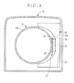
Fig. 4 is a section illustrating a television lens apparatus; -
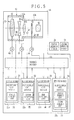
Fig. 5 is a block diagram illustrating electrical construction of the television lens apparatus; -
Fig. 6 is a section illustrating a state of inserting a circuit board; -
Fig. 7 is a section illustrating the television lens apparatus in a state of setting the circuit board; -
Fig. 8 is a perspective illustrating a second embodiment in which a connector is rotatable; -
Fig. 9 is an explanatory view illustrating a state of the connector set in a first position; -
Fig. 10 is an explanatory view illustrating a state of the connector set in a second position; -
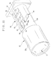
Fig. 11 is a perspective illustrating a third embodiment in which a circuit board is inserted in a tangential direction of the lens barrel. - [First embodiment] As illustrated in
Fig. 1 , atelevision lens apparatus 10 includes an imagingoptical system 11, alens barrel 12, ahousing 13 and amount 14, the imagingoptical system 11 focusing an object image, thelens barrel 12 holding the imagingoptical system 11, thehousing 13 containing thelens barrel 12, themount 14 coupling thetelevision lens apparatus 10 to a television camera apparatus (not shown) in a removable manner. - The imaging
optical system 11 is constituted by a plurality of lens groups, an iris device and the like. Thelens barrel 12 is cylindrical (seeFig. 3 ). Thehousing 13 is in a shape of a quadrilateral prism, and nearly as long as thelens barrel 12. Thehousing 13 covers an outer surface of thelens barrel 12 so as to uncover an entrance end and exit end of the imagingoptical system 11 at its two ends. - As illustrated in
Fig. 2 , aboard holding device 15 is contained in thehousing 13. Theboard holding device 15 is disposed in a space defined between thelens barrel 12 and thehousing 13. Theboard holding device 15 supports first to fourth circuit boards 21-24 for controlling thetelevision lens apparatus 10 in a removable manner. The circuit boards 21-24 are formed in a substantially equal shape. Theboard holding device 15 supports the circuit boards 21-24 in alignment in an optical axis direction to extend transversely to the optical axis of the imagingoptical system 11. - An
opening 16 is formed in a lateral surface of thehousing 13 for uncovering theboard holding device 15. Theopening 16 is quadrilateral and large enough to mount and dismount the circuit boards 21-24 in relation to theboard holding device 15. Arotatable lid 17 is connected to thehousing 13 by hinges. Thelid 17 is movable between an open position for enabling mounting and dismounting of each of the circuit boards 21-24 by uncovering theopening 16 and a closed position for closing theopening 16. - The circuit boards 21-24 supported on the
board holding device 15 are covered and protected by thehousing 13 and thelid 17 in the closed position. Assuming that breakage occurs with the circuit boards 21-24, thelid 17 can be moved to the open position to facilitate the mounting and dismounting of the circuit boards 21-24 through theopening 16. It is preferable to lock thelid 17 in the closed position by use of screws or the like. - As illustrated in
Fig. 3 , thelens barrel 12 has afront portion 12a and arear portion 12b. Therear portion 12b has a smaller diameter than thefront portion 12a. The shape of thelens barrel 12 is derived from the form of the respective lenses included in the imagingoptical system 11 to decrease in a direction toward the exit end. Amount frame 18 is disposed at an end of therear portion 12b for partially constituting themount 14 upon being contained in thehousing 13. - As the
board holding device 15 is attached to the lateral surface of therear portion 12b with the smaller diameter, the size of the circuit boards 21-24 can be enlarged. Moving the circuit boards 21-24 in and out is also easy. - As illustrated in
Figs. 3 and4 , a substantiallysemicircular cutout 21a is formed in thefirst circuit board 21 at one of longer side lines of the quadrilateral according to a diameter of therear portion 12b. Aquadrilateral insert portion 21b projects from the vicinity of the center of thefirst circuit board 21 for insertion in theboard holding device 15. Plural electrodes are disposed on theinsert portion 21b for use in electrical connection with theboard holding device 15. The second to fourth circuit boards 22-24 are constructed similarly to thefirst circuit board 21, so that their explanation is omitted. - The
board holding device 15 is constituted by fourconnectors 30 and aquadrilateral wiring board 31, theconnectors 30 being associated with respectively the circuit boards 21-24, thewiring board 31 supporting each of theconnectors 30. Each of theconnectors 30 has a receivingopening 30a for receiving entry ofinsert portions 21b-24b of the circuit boards 21-24. The entry to the receivingopening 30a electrically interconnects the circuit boards 21-24, and mechanically keeps those supported. Theconnectors 30 are attached to thewiring board 31 at a constant interval so as to arrange longer side lines of the receivingopening 30a parallel with one another. - On the
wiring board 31 are provided connection circuits for electrically interconnecting the circuit boards 21-24 inserted in respectively theconnectors 30. Thus, it is possible to couple the circuit boards 21-24 only by inserting each of theinsert portions 21b-24b of the circuit boards 21-24 into the receivingopening 30a of theconnectors 30, and to interconnect the circuit boards 21-24 electrically. - Substantially circular through holes are formed at four corners of the
wiring board 31. Fourbosses 32 are formed on therear portion 12b of thelens barrel 12 to project toward theopening 16. Theboard holding device 15 is attached to a lateral side of therear portion 12b of thelens barrel 12 by engaging the through holes of thewiring board 31 with respectively thebosses 32. This being so, theconnectors 30 are arranged in the optical axis direction in a state of orienting the receivingopenings 30a to theopening 16. A center of each of the receivingopening 30a is positioned substantially as high as the central axis of thelens barrel 12. - Accordingly, the
board holding device 15 supports the circuit boards 21-24 arranged in the optical axis direction in such a state that the surface of each of the circuit boards 21-24 is substantially perpendicular to the optical axis of the imagingoptical system 11 andcutouts 21a-24a are fitted on the outer surface of thelens barrel 12. - As illustrated in
Fig. 5 , the imagingoptical system 11 includes afocus lens group 40 for focus adjustment, azoom lens group 41a and acorrection lens group 41b for magnification adjustment, aniris device 42 for adjusting a light amount, and arelay lens group 43 for transmitting a focused object image to the television camera apparatus. Each of thelens groups lens groups - The
focus lens group 40, thezoom lens group 41a and thecorrection lens group 41b are kept contained in thelens barrel 12 movably with respective lens holders as is well-known in the art. At the time of focus adjustment, thefocus lens group 40 moves in the optical axis direction to adjust the focus of the imagingoptical system 11 according to a subject distance. At the time of adjusting the magnification, thezoom lens group 41a moved in the optical axis direction according to a focal length. Thecorrection lens group 41b moves to compensate for an offset in the focusing according to thezoom lens group 41a. - The
television lens apparatus 10 includes afocus motor 44 for moving thefocus lens group 40 in the optical axis direction by use of a focus ring or screw shaft, and afocus sensor 45 for detecting a position of thefocus lens group 40. Also, there are provided azoom motor 46 for moving thezoom lens group 41a and thecorrection lens group 41b in the optical axis direction, and azoom sensor 47 for detecting their positions. Also, there are provided aniris motor 48 for driving theiris device 42, and aniris sensor 49 for detecting an adjustment amount of theiris device 42. Themotors sensors lens barrel 12. Also, themotors sensors wiring board 31 electrically. - A
focus demand device 50 as an external operable device for focus adjustment, and azoom demand device 51 as an operable device for magnification adjustment are attached to a camera stand for supporting the television camera apparatus in a rotatable manner. Thefocus demand device 50 and thezoom demand device 51 are connected to thetelevision lens apparatus 10 by a connector, cable or the like. Note that thefocus demand device 50 and thezoom demand device 51 can be connected to the television camera apparatus. For this structure, the television camera apparatus is connected to thewiring board 31 in thetelevision lens apparatus 10 with contact points and wiring in themount 14. - The
focus demand device 50 has a rotatable operation wheel (not shown). Thefocus demand device 50 generates a focus demand signal according to a rotational operation amount and operating direction of the operation wheel, and inputs the focus demand signal to thetelevision lens apparatus 10. Thezoom demand device 51 includes a thumb ring (not shown) rotatable in two directions from a reference position. Thezoom demand device 51 generates a zoom demand signal according to a rotational operation amount and operating direction of the thumb ring, and inputs the zoom demand signal to thetelevision lens apparatus 10. -
Adjustable circuit devices 21c-24c are provided in respectively the circuit boards 21-24. Theadjustable circuit devices 21c-24c are constituted by a programmable logic device such as an FPGA, and a rewritable non-volatile memory such as an EEPROM, and can be set up for an electronic circuit (functional circuit) as desired by use of software. - The circuit boards 21-24 are common circuit boards having the same shape and the same electrical construction. In the
television lens apparatus 10, theadjustable circuit devices 21c-24c of the circuit boards 21-24 are set up for electronic circuits different from one another, to function the circuit boards 21-24 differently from one another. - Thus, a manufacturing cost can be decreased in comparison with discrete preparation of special circuit boards owing to the common specifics of the circuit boards 21-24. Addition and change of the functions can be carried out easily only by changing the electronic circuits in the
adjustable circuit devices 21c-24c. Furthermore, breakage of any one of the circuit boards 21-24 can be coped with by preparing one new circuit board, to keep a maintaining expense low for thetelevision lens apparatus 10. - The
adjustable circuit device 21c of thefirst circuit board 21 is set up as afocus control circuit 54 for controlling the focus adjustment of the imagingoptical system 11. Theadjustable circuit device 22c of thesecond circuit board 22 is set up as azoom control circuit 55 for controlling the magnification adjustment of the imagingoptical system 11. Theadjustable circuit device 23c of thethird circuit board 23 is set up as aniris control circuit 56 for controlling theiris device 42 of the imagingoptical system 11. Theadjustable circuit device 24c of thefourth circuit board 24 is set up as afocus demand circuit 57 and azoom demand circuit 58. - The circuit boards 21-24 are connected with one another electrically by the
wiring board 31. Thefourth circuit board 24 is electrically connected to thefocus demand device 50 and thezoom demand device 51 by thewiring board 31. Thefocus demand circuit 57 receives a focus demand signal from thefocus demand device 50, and inputs the focus demand signal to thefocus control circuit 54 in thefirst circuit board 21. Thezoom demand circuit 58 receives a zoom demand signal from thezoom demand device 51, and then inputs the zoom demand signal to thezoom control circuit 55 of thesecond circuit board 22. - The
first circuit board 21 is electrically connected to thefocus motor 44 and thefocus sensor 45 by thewiring board 31. Thefocus control circuit 54 drives thefocus motor 44 according to a detection result of thefocus sensor 45 and a focus demand signal from thefocus demand circuit 57, and adjusts the focus of the imagingoptical system 11 by moving thefocus lens group 40 in the optical axis direction. - The
second circuit board 22 is electrically connected to thezoom motor 46 and thezoom sensor 47 by thewiring board 31. Thezoom control circuit 55 drives thezoom motor 46 according to a detection result of thezoom sensor 47 and a zoom demand signal from thezoom demand circuit 58, and adjusts the magnification of the imagingoptical system 11 by moving thezoom lens group 41a and thecorrection lens group 41b respectively in the optical axis direction. - For use of the
television lens apparatus 10, thetelevision lens apparatus 10 is mounted on the front side of the television camera apparatus, and connected to thefocus demand device 50 and thezoom demand device 51 by a cable or the like. An operation wheel of thefocus demand device 50, a thumb ring of thezoom demand device 51 and the like are operated to carry out the focus adjustment, magnification adjustment and light amount adjustment. - For example, assuming that the
first circuit board 21 is broken, thefocus control circuit 54 is set up in an adjustable circuit device of a new circuit board designed commonly, to construct thefirst circuit board 21 newly. Then thelid 17 of thetelevision lens apparatus 10 is moved from the closed position to the open position. Thefirst circuit board 21 being broken is pulled out of theboard holding device 15 through theopening 16. Then theinsert portion 21b of thefirst circuit board 21 formed newly is inserted in the receivingopening 30a of a corresponding one of theconnectors 30 to connect the newfirst circuit board 21 to theboard holding device 15. - This being so, it is possible easily to mount and dismount each of the circuit boards 21-24 through the
opening 16 by opening thelid 17. As the circuit boards 21-24 are respectively supported on theboard holding device 15, the circuit boards 21-24 are electrically connected to one another by thewiring board 31. Thus, no cable or the like can be used for interconnecting the circuit boards 21-24. Manipulation for the wiring can be saved. - In the above embodiment, the
insert portion 21b is formed near to the center of thecutouts 21a-24a of respectively the circuit boards 21-24. However, acircuit board 60 and aboard holding device 61 can be provided as illustrated inFigs. 6 and7 . A substantiallysemicircular cutout 60a is formed in thecircuit board 60. Aquadrilateral insert portion 60b is formed by elongating a lower portion of thecircuit board 60 without having thecutout 60a. - In a manner similar to the above embodiment, the
board holding device 61 is constituted by aconnector 62 and awiring board 63. A quadrilateral receiving opening is formed in each of theconnector 62 in compliance with a shape of theinsert portion 60b. Theboard holding device 61 is attached to the lateral side of therear portion 12b of thelens barrel 12 by use ofbosses 64, so as to set a longitudinal direction of the receiving opening of theconnector 62 vertically, position the receiving opening lower than thelens barrel 12, and orient the receiving opening to theopening 16. - Even in the
board holding device 61 constructed above, the optical axis of the imagingoptical system 11 and the surface of thecircuit board 60 are oriented substantially perpendicular with one another. Thelens barrel 12 partially enters thecutout 60a. It is possible with thecircuit board 60 and theboard holding device 61 to obtain effects similar to the above-described embodiment. - Although the
board holding device 61 is so disposed as to form theinsert portion 60b lower than thecutout 60a and position the receiving opening lower than thelens barrel 12 in the example ofFigs. 6 and7 , it is possible in contrast with this to dispose theboard holding device 61 so as to form theinsert portion 60b on an upper side of thecutout 60a and position the receiving opening higher than thelens barrel 12. Furthermore, twoboard holding devices 61 can be used so as to form theinsert portion 60b on each of upper and lower sides of thecutout 60a and position the receiving opening in each of upper and lower sides of thelens barrel 12. - In the above embodiment, the
cutouts 21a-24a of the substantially semicircular shape are formed in respectively the circuit boards 21-24. However, the shape of thecutouts 21a-24a can be an arcuate shape, U shape, polygonal shape or the like as desired for enabling partial entry of thelens barrel 12. - [Second embodiment] A second embodiment of the present invention as illustrated in
Figs. 8-10 is described next. Elements of which a function and structure are the same as those of the above-described first embodiment are designated with identical reference numerals, their explanation being omitted. Acircuit board 70 is quadrilateral. Aninsert portion 70a with plural electrodes is formed with one of side lines of thecircuit board 70 of a plate shape. - A
board holding device 71 is constituted by fourconnectors 72 and awiring board 73. Aquadrilateral receiving opening 72a is formed in each of theconnectors 72 in compliance with a shape of theinsert portion 70a of thecircuit board 70.Rotational shafts 72b are formed at respectively ends of each of theconnectors 72. Therotational shafts 72b are received in a rotatable manner in through holes in a pair offlanges 74 formed on thewiring board 73. Each of theconnectors 72 is supported by the pair of theflanges 74 in a rotatable manner, and is so attached to thewiring board 73 that longer side lines of the receivingopenings 72a extend in parallel with one another. - Through
holes 73a are formed at four corners of thewiring board 73. As illustrated inFig. 9 , fourbosses 75 are formed on the lateral surface of thelens barrel 12 and positioned in association with respectively the throughholes 73a. Theboard holding device 71 is attached to a lateral side of therear portion 12b of thelens barrel 12 by engaging the throughholes 73a of thewiring board 73 with respectively thebosses 75, so that theconnectors 72 are arranged in the optical axis direction in a state of orienting the receivingopening 72a to theopening 16, and that a center of each receivingopening 72a is positioned substantially as high as the central axis of thelens barrel 12. - Each of the
connectors 72 is supported on thewiring board 73 in a rotatable manner by theflanges 74, and rotates between a first position of orienting the receivingopening 72a to theopening 16 as illustrated inFig. 9 and a second position of inclining the receivingopening 72a with respect to theopening 16 as illustrated inFig. 10 . - To couple the
circuit board 70 to theboard holding device 71, thelid 17 is opened and then theconnector 72 is returned to the first position. Thecircuit board 70 is inserted in theboard holding device 71. Then theconnector 72 is shifted to the second position to contain thecircuit board 70 in thehousing 13. Finally, thelid 17 is closed. - Consequently, the
circuit board 70 of the greater width than the space between thelens barrel 12 and thehousing 13 can be used as thecircuit board 70 is contained with an inclination. The space between thelens barrel 12 and thehousing 13 can be utilized effectively. To mount and dismount thecircuit board 70, theconnector 72 is returned to the first position. Thecircuit board 70 can be mounted and dismounted easily, as thecircuit board 70 can be moved in and out in a direction perpendicular to theopening 16. - [Third embodiment] A third embodiment of the present invention as illustrated in
Fig. 11 is described next. Acircuit board 80 is quadrilateral. Aninsert portion 80a with plural electrodes is formed with one of shorter side lines of thecircuit board 80. - A
board holding device 81 is constituted by awiring board 83 and fourconnectors 82 attached thereto. Aquadrilateral receiving opening 82a is formed in each of theconnectors 82 in compliance with a shape of theinsert portion 80a of thecircuit board 80. Each of theconnectors 82 is so attached to thewiring board 83 that the receivingopening 82a is oriented in parallel with the surface of thewiring board 83 and the receivingopening 82a are aligned. - Through holes are formed at four corners of the
wiring board 83, and receive insertion of respectivelybosses 84 on thelens barrel 12, so that thewiring board 83 is attached to a lateral upper side of therear portion 12b of thelens barrel 12 in a tangential direction. Theconnectors 82 are arranged in the optical axis direction in a state of orienting the receivingopening 82a to theopening 16. - It is possible in the third embodiment to obtain effects similar to the first embodiment. The
board holding device 81, although disposed higher than thelens barrel 12, can be disposed lower than thelens barrel 12. Also, theboard holding device 81 can be disposed on each of upper and lower sides of thelens barrel 12. - In the above embodiments, the
focus control circuit 54, thezoom control circuit 55 or the like is formed on the circuit board. However, other electronic circuits can be formed. For example, an extender control circuit for controlling a change in the magnification of an extending mechanism is formed on a circuit board assuming that the extending mechanism is used for changing the magnification by setting one of the plural zooming lenses on an optical axis. - Also, it is possible to use a diagnosis device for diagnosis as to whether the
focus control circuit 54, thezoom control circuit 55 or the like on the circuit boards operates suitably, or a network connection device for connecting the television lens apparatus to the Internet or other network, so that a result of the diagnosis of the diagnosis device can be transmitted by the network to an external server or the like. Thus, it is possible on a manufacturer side to manage a status of operation or occurrence of breakage of the circuit boards in the television lens apparatus installed in a studio or the like. Maintainability can be increased. Note that the diagnosis device and the network connection device can be disposed on a circuit board disposed in a stationary manner in the housing in place of being disposed on the removable circuit board. - In each of the above embodiments, the plural connectors are disposed on the board holding device. The plural circuit boards are directly inserted in the connectors to support the circuit boards on the board holding device. However, the method of supporting the circuit boards is not limited to this. For example, an adapter capable of supporting the circuit boards is used and supported on the board holding device of a television lens apparatus. Thus, it is possible to interconnect the circuit boards and the board holding device electrically and mechanically by use of the adapter.
- The number of the circuit boards is not limited to four but can be 1-3 or 5 or higher. Also, the circuit boards are the common electronic circuits in the above embodiments. Their function is changed according to the use. However, special circuit boards can be used as designed separately between the functions.
- In each of the above embodiments, the
lid 17 rotatable about the optical axis direction is used. However, rotational shafts of thelid 17 can be directed in any direction as desired. Also, thelid 17, without limitation to one for rotating about hinges, can be moved between the open and closed positions by sliding or the like. Furthermore, thelid 17 can be a removable lid for closing theopening 16 upon being fitted on thehousing 13 and for uncovering theopening 16 upon being removed from thehousing 13. - In each of the above embodiments, the
lens barrel 12 of the cylindrical shape is illustrated. However, a shape of thelens barrel 12 can be a prismatic tube or elliptic cylinder. To this end, therear portion 12b can have a less wide shape than thefront portion 12a. -
- 10
- television lens apparatus
- 11
- imaging optical system
- 12
- lens barrel
- 13
- housing
- 15
- board holding device
- 16
- opening
- 17
- lid
- 21-24
- circuit boards
- 21a-24a
- cutouts
- 21b-24b
- insert portions
- 21c-24c
- adjustable circuit devices
- 30
- connectors
- 30a
- receiving opening
- 31
- wiring board
Claims (13)
- A television lens apparatus having an imaging optical system for focusing an object image, a lens barrel for holding said imaging optical system, and a housing for covering and protecting said imaging optical system and said lens barrel, said television lens apparatus characterized in comprising:plural circuit boards for controlling said television lens apparatus;a board holding device for electrically interconnecting said plural circuit boards, and holding said circuit boards removably to contain said plural circuit boards in a space between said lens barrel and said housing;an opening, formed in said housing, for enabling mounting and dismounting of said plural circuit boards with said board holding device; anda lid for opening and closing said opening.
- A television lens apparatus as defined in claim 1, characterized in that each of said circuit boards is substantially in a plate shape and has an insert portion on one side line thereof;
said board holding device includes plural connectors having a receiving opening for entry of said insert portion, and a wiring board to which said connectors are coupled in alignment with an optical axis of said imaging optical system and for electrical connection with said circuit boards entered in respectively said connectors. - A television lens apparatus as defined in claim 2, characterized in that said lens barrel is cylindrical with a front portion of a large diameter and a rear portion of a small diameter, and said board holding device is mounted on said rear portion; and
said housing is in a shape of a prismatic tube. - A television lens apparatus as defined in claim 2, characterized in that said connector supports said circuit board in a state substantially perpendicular to said optical axis.
- A television lens apparatus as defined in claim 4, characterized in that a cutout is formed in each of said circuit boards in compliance with a shape of said lens barrel.
- A television lens apparatus as defined in claim 5, characterized in that said insert portion is formed near to a center of said cutout;
said board holding device is mounted on a lateral surface of said lens barrel to set a center of said respective receiving opening at a height substantially equal to a height of a central axis of said lens barrel. - A television lens apparatus as defined in claim 5, characterized in that said insert portion is formed on at least one of upper and lower sides of said cutout;
said board holding device is mounted on a lateral surface of said lens barrel to position said receiving opening on at least one of upper and lower sides of said lens barrel in association with said insert portion. - A television lens apparatus as defined in claim 2, characterized in that each of said connectors is coupled to said wiring board in a rotatable manner between a first position for orienting said receiving opening to said opening and a second position for inclining said receiving opening relative to said opening.
- A television lens apparatus as defined in claim 2, characterized in that said connectors support respectively said circuit boards in a direction of setting surfaces of said circuit boards substantially in parallel with said optical axis and substantially flush with one another.
- A television lens apparatus as defined in claim 2, characterized in that said lid is coupled to said housing in a rotatable manner to move between an open position for uncovering said opening to enable mounting and dismounting of said circuit boards and a closed position for closing said opening.
- A television lens apparatus as defined in any one of claims 1 to 11, characterized in that each of said circuit boards includes an adjustable circuit device in which an electronic circuit as desired is settable with software, and said circuit boards are boards with a common shape and common electrical structure.
- A television lens apparatus as defined in claim 11, characterized in that said imaging optical system has a focus lens, a zoom lens, a correction lens, a relay lens and an iris device.
- A television lens apparatus as defined in claim 12, characterized in that said plural circuit boards are set in any one of electronic circuits including a focus control circuit for moving said focus lens for focus adjustment, a zoom control circuit for moving said zoom lens and said correction lens for magnification adjustment, and an iris control circuit for controlling said iris device.
Applications Claiming Priority (2)
| Application Number | Priority Date | Filing Date | Title |
|---|---|---|---|
| JP2011193930 | 2011-09-06 | ||
| PCT/JP2012/072140 WO2013035637A1 (en) | 2011-09-06 | 2012-08-31 | Television lens device |
Publications (2)
| Publication Number | Publication Date |
|---|---|
| EP2755073A1 true EP2755073A1 (en) | 2014-07-16 |
| EP2755073A4 EP2755073A4 (en) | 2015-04-15 |
Family
ID=47832084
Family Applications (1)
| Application Number | Title | Priority Date | Filing Date |
|---|---|---|---|
| EP12829845.2A Withdrawn EP2755073A4 (en) | 2011-09-06 | 2012-08-31 | Television lens device |
Country Status (4)
| Country | Link |
|---|---|
| US (1) | US9065995B2 (en) |
| EP (1) | EP2755073A4 (en) |
| JP (1) | JP5784128B2 (en) |
| WO (1) | WO2013035637A1 (en) |
Families Citing this family (7)
| Publication number | Priority date | Publication date | Assignee | Title |
|---|---|---|---|---|
| KR102244153B1 (en) * | 2013-09-13 | 2021-04-23 | 엘지이노텍 주식회사 | Camera module |
| JP6584246B2 (en) * | 2015-09-09 | 2019-10-02 | キヤノン株式会社 | Imaging device |
| USD837927S1 (en) * | 2016-05-27 | 2019-01-08 | Aimpoint Ab | Sight |
| USD827083S1 (en) * | 2016-11-03 | 2018-08-28 | Huntercraft Limited | Electronic sight |
| USD882717S1 (en) * | 2018-01-22 | 2020-04-28 | Rade Tecnologias, S.L. | Housing for an optical system of small and light firearms |
| CN111481167A (en) * | 2020-06-02 | 2020-08-04 | 重明鸟(苏州)智能技术有限公司 | High-speed focusing device |
| CN113315893B (en) * | 2021-05-17 | 2023-10-27 | 杭州海康威视数字技术股份有限公司 | Cameras and video equipment |
Family Cites Families (16)
| Publication number | Priority date | Publication date | Assignee | Title |
|---|---|---|---|---|
| JPH01145184U (en) * | 1988-03-30 | 1989-10-05 | ||
| US5221964A (en) * | 1991-08-05 | 1993-06-22 | Dalsa Inc | Electronically expandable modular ccd camera |
| JP3084455B2 (en) * | 1991-09-02 | 2000-09-04 | コニカ株式会社 | Memory card loading / unloading device |
| JP3284585B2 (en) * | 1992-04-10 | 2002-05-20 | ソニー株式会社 | Electronic equipment cooling device |
| JPH09179013A (en) * | 1995-12-27 | 1997-07-11 | Fuji Photo Optical Co Ltd | Television lens |
| JPH09252190A (en) * | 1996-03-14 | 1997-09-22 | Mitsubishi Electric Corp | Semicircular substrate holding mechanism |
| JP2000332464A (en) * | 1999-05-21 | 2000-11-30 | Sony Corp | Wiring board holding device and video camera for electronic equipment |
| KR200252100Y1 (en) * | 2001-08-07 | 2001-11-23 | 정운기 | Bullet camera for closed circuit television |
| US7327396B2 (en) * | 2002-04-10 | 2008-02-05 | National Instruments Corporation | Smart camera with a plurality of slots for modular expansion capability through a variety of function modules connected to the smart camera |
| JP2003301994A (en) * | 2002-04-10 | 2003-10-24 | Matsushita Electric Ind Co Ltd | Bearing integrated rotation device |
| US6830387B2 (en) * | 2002-12-17 | 2004-12-14 | Raytheon Company | Modular thermal security camera system |
| JP2005352281A (en) * | 2004-06-11 | 2005-12-22 | Fujinon Corp | Television lens apparatus |
| US7634193B2 (en) * | 2005-09-27 | 2009-12-15 | Lang Mekra North America, Llc | Printed circuit board assembly |
| JP4761211B2 (en) * | 2006-11-14 | 2011-08-31 | 富士フイルム株式会社 | TV lens device |
| US8269893B2 (en) * | 2008-05-12 | 2012-09-18 | Flir Systems, Inc. | Optical payload electrical system |
| US8118499B2 (en) * | 2010-05-19 | 2012-02-21 | LIR Systems, Inc. | Infrared camera assembly systems and methods |
-
2012
- 2012-08-31 WO PCT/JP2012/072140 patent/WO2013035637A1/en not_active Ceased
- 2012-08-31 JP JP2013532566A patent/JP5784128B2/en not_active Expired - Fee Related
- 2012-08-31 EP EP12829845.2A patent/EP2755073A4/en not_active Withdrawn
-
2014
- 2014-03-05 US US14/198,236 patent/US9065995B2/en not_active Expired - Fee Related
Also Published As
| Publication number | Publication date |
|---|---|
| US9065995B2 (en) | 2015-06-23 |
| EP2755073A4 (en) | 2015-04-15 |
| US20140184886A1 (en) | 2014-07-03 |
| JP5784128B2 (en) | 2015-09-24 |
| WO2013035637A1 (en) | 2013-03-14 |
| JPWO2013035637A1 (en) | 2015-03-23 |
Similar Documents
| Publication | Publication Date | Title |
|---|---|---|
| US9065995B2 (en) | Television lens apparatus | |
| CN101393380B (en) | Digital camera system and digital camera body | |
| KR102419783B1 (en) | Lens mount, accessory, and camera mount | |
| KR20210042883A (en) | Accessory, image pickup apparatus on which same is mountable, and camera system | |
| CN101887206B (en) | Image pickup apparatus | |
| JP6427287B1 (en) | Accessory device, camera, communication control program, and camera system | |
| JP6033015B2 (en) | Optical equipment | |
| EP3112913B1 (en) | Lens barrel, imaging element support structure, electronic view finder, and imaging device | |
| JPWO2014115274A1 (en) | CCTV lens and correction method of CCTV lens | |
| CN111120790B (en) | Camera pan-tilt system | |
| US20060209437A1 (en) | Lens barrel | |
| CN111123622B (en) | Camera PTZ System | |
| JP5706592B2 (en) | LENS DEVICE AND IMAGING DEVICE | |
| CN213754663U (en) | Image pickup apparatus | |
| JP4867707B2 (en) | Lens barrel, imaging device, and optical axis adjustment method | |
| EP2737366B1 (en) | Camera with internal assembly frame and process for assembling the camera | |
| JP5706593B2 (en) | LENS DEVICE AND IMAGING DEVICE | |
| JP4924631B2 (en) | Lens barrel and imaging device | |
| EP4071549B1 (en) | Lens device | |
| KR100868276B1 (en) | Multimedia video camera device for microscope | |
| JP5754213B2 (en) | Hinge unit and electronic device | |
| US5774280A (en) | Lens barrel and optical apparatus | |
| KR20220133570A (en) | Apparatus for testing camera module | |
| US20070109671A1 (en) | Lens barrel and image pickup apparatus | |
| WO2011056012A2 (en) | Lens system for photographing stereoscopic images |
Legal Events
| Date | Code | Title | Description |
|---|---|---|---|
| PUAI | Public reference made under article 153(3) epc to a published international application that has entered the european phase |
Free format text: ORIGINAL CODE: 0009012 |
|
| 17P | Request for examination filed |
Effective date: 20140306 |
|
| AK | Designated contracting states |
Kind code of ref document: A1 Designated state(s): AL AT BE BG CH CY CZ DE DK EE ES FI FR GB GR HR HU IE IS IT LI LT LU LV MC MK MT NL NO PL PT RO RS SE SI SK SM TR |
|
| DAX | Request for extension of the european patent (deleted) | ||
| RA4 | Supplementary search report drawn up and despatched (corrected) |
Effective date: 20150317 |
|
| RIC1 | Information provided on ipc code assigned before grant |
Ipc: H05K 7/14 20060101ALI20150311BHEP Ipc: H04N 5/225 20060101ALI20150311BHEP Ipc: G02B 7/02 20060101AFI20150311BHEP |
|
| STAA | Information on the status of an ep patent application or granted ep patent |
Free format text: STATUS: THE APPLICATION IS DEEMED TO BE WITHDRAWN |
|
| 18D | Application deemed to be withdrawn |
Effective date: 20190301 |