EP2755068A1 - Optical fiber-type optical functional element cartridge module - Google Patents
Optical fiber-type optical functional element cartridge module Download PDFInfo
- Publication number
- EP2755068A1 EP2755068A1 EP12830065.4A EP12830065A EP2755068A1 EP 2755068 A1 EP2755068 A1 EP 2755068A1 EP 12830065 A EP12830065 A EP 12830065A EP 2755068 A1 EP2755068 A1 EP 2755068A1
- Authority
- EP
- European Patent Office
- Prior art keywords
- optical
- optical fiber
- module
- collimator
- collimators
- Prior art date
- Legal status (The legal status is an assumption and is not a legal conclusion. Google has not performed a legal analysis and makes no representation as to the accuracy of the status listed.)
- Granted
Links
Images

Classifications
-
- G—PHYSICS
- G02—OPTICS
- G02B—OPTICAL ELEMENTS, SYSTEMS OR APPARATUS
- G02B6/00—Light guides; Structural details of arrangements comprising light guides and other optical elements, e.g. couplings
- G02B6/24—Coupling light guides
- G02B6/26—Optical coupling means
-
- G—PHYSICS
- G02—OPTICS
- G02B—OPTICAL ELEMENTS, SYSTEMS OR APPARATUS
- G02B6/00—Light guides; Structural details of arrangements comprising light guides and other optical elements, e.g. couplings
- G02B6/24—Coupling light guides
- G02B6/26—Optical coupling means
- G02B6/264—Optical coupling means with optical elements between opposed fibre ends which perform a function other than beam splitting
-
- G—PHYSICS
- G02—OPTICS
- G02B—OPTICAL ELEMENTS, SYSTEMS OR APPARATUS
- G02B6/00—Light guides; Structural details of arrangements comprising light guides and other optical elements, e.g. couplings
- G02B6/24—Coupling light guides
- G02B6/26—Optical coupling means
- G02B6/32—Optical coupling means having lens focusing means positioned between opposed fibre ends
-
- G—PHYSICS
- G02—OPTICS
- G02B—OPTICAL ELEMENTS, SYSTEMS OR APPARATUS
- G02B6/00—Light guides; Structural details of arrangements comprising light guides and other optical elements, e.g. couplings
- G02B6/24—Coupling light guides
- G02B6/36—Mechanical coupling means
- G02B6/3616—Holders, macro size fixtures for mechanically holding or positioning fibres, e.g. on an optical bench
Definitions
- the present invention relates to an optical fiber-based optical functional device cartridge module.
- Patent Literature 1 discloses an optical functional device cartridge module.
- a cartridge type optical functional module disclosed in this document is to be used for bulk optical functional devices.
- Patent Literature 1 JP 3933967 B1
- the present invention is basically based on a finding that good optical coupling between optical fiber collimators at both ends of a module can be achieved by mounting collimators and providing an alignment mechanism for the collimator in a cartridge.
- the present invention is based on a finding that an optical fiber-based module including an EDFA or a waveguide-based module can be mounted in a cartridge since good optical coupling between optical fiber collimators at both ends of a module can be achieved.
- a cartridge type optical functional module 10 includes: first and second optical fiber collimators 2 and 3 opposed to each other; an optical functional object 5, and a base part 7 in which the optical functional object 5 is detachably placed.
- the first and second optical fiber collimators 2 and 3 are fixed to the base part 7.
- the optical functional object 5 includes at least one optical device 4 having an optical function placed therein and positioned to be able to couple between the first and second optical fiber collimators 2 and 3.
- the optical device 4 is an optical fiber-based module or a waveguide-based module.
- the optical functional object 5 includes a third collimator 13, and a first alignment mechanism 17 to align the position of the third collimator 13 in the optical functional object 5.
- the first alignment mechanism 17 is preferably a mechanism to align vertical and horizontal positions of the third collimator 13.
- the optical device 4 is preferably an optical fiber amplifier.
- the optical device 4 is preferably an optical delay circuit.
- good optical coupling between optical fiber collimators at both ends of a module can be achieved by mounting an optical fiber collimator also in each cartridge and also providing an alignment mechanism for the optical fiber collimator in each cartridge.
- an optical fiber-based module or a waveguide-based module can be mounted in a cartridge.
- the present invention provides an optical fiber-based optical functional device cartridge module capable of optical amplification by using an EDFA module as the optical fiber-based module.
- At least cartridges positioned at both ends include collimators.
- the shape of cartridges is devised so as to allow fine alignment of the positions of the collimators, for example.
- a collimator insertion portion is provided at the center of a cartridge, and an alignment mechanism is provided in an upper hole and a hole in the lateral direction of the collimator insertion portion.
- the positions of the collimators can be aligned after multiple cartridges are mounted on the base so as to optimize optical coupling of the cartridges and optical coupling with optical fiber collimators.
- the alignment mechanism include a screw that can be manually moved and an actuator that can move the positions according to an electric instruction.
- the alignment mechanism can optimize the positions of the collimators, which allows optimum optical coupling when an optical fiber-based or waveguide-based optical device is used.
- Fig. 1 is a conceptual diagram for explaining a configuration of a cartridge type optical functional module according to the present invention.
- a cartridge type optical functional module 10 according to the present invention includes first and second optical fiber collimators 2 and 3 that are opposed to each other, an optical functional object 5, and a base part 7 that connects the first and second optical fiber collimators 2 and 3 and in which the optical functional object 5 is detachably placed.
- the optical functional object 5 is a cartridge in which at least one optical device 4 having an optical function is placed in a manner allowing optical coupling between the first and second optical fiber collimators 2 and 3.
- three optical functional objects 5 that are cartridges are included.
- the cartridge type optical functional module basically has the same functions as the cartridge type optical functional module disclosed in Patent Literature 1. Specifically, the first and second optical fiber collimators 2 and 3 are provided with a predetermined space at both ends of the base part 7. In addition, a predetermined number of optical functional objects 5 can be installed in the form of cartridges between the first and second optical fiber collimators 2 and 3 and fixed to the base part 7. The optical devices in the respective cartridges and the first and second optical fiber collimators 2 and 3 are optically coupled.
- the cartridge type optical functional module 10 can thus be used as a module having various optical functions by replacing the cartridges.
- the first and second optical fiber collimators 2 and 3 each have an optical fiber part and a collimator part.
- the collimator part and the optical fiber part are connected in a manner that light can be transmitted therebetween.
- the collimator part of the first optical fiber collimator 2 and the collimator part of the second optical fiber collimator 3 are opposed with a space above the base part 7 therebetween. Within this space, a predetermined number of cartridges can be inserted.
- the first and second optical fiber collimators 2 and 3 each preferably have a second alignment mechanism for alignment the position of the collimator part.
- An example of such as alignment mechanism is a mechanism that can move the collimator part vertically or horizontally.
- Another example of the alignment mechanism is a mechanism that can align the vertical position of the collimator by pushing the collimator from above or underneath with a screw or an actuator like a collimator alignment mechanism to be described later.
- Still another example of the position alignment mechanism is a mechanism that can align the lateral position of the collimator by pushing the collimator from the right or the left with a screw or an actuator like a collimator alignment mechanism to be described later.
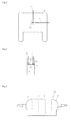
- Fig. 2 is a diagram for explaining an example external appearance of an optical functional object according to the present invention.
- the optical functional object 5 is of a cartridge type object in which an optical device 4 is placed.
- the optical device 4 is positioned so as to allow optical coupling between the first and second optical fiber collimators 2 and 3 with a third collimator 13 to be described later.
- the number of optical functional objects 5 may be one or may be two or more. When the number of optical functional objects 5 is one, two collimators and an optical device may be provided.
- the two collimators are optically connected to the optical device and each can be optically coupled between the first and second optical fiber collimators 2 and 3.
- the optical functional objects 5 may have the same function or may have different functions.
- all the optical functional objects need not have optical fiber-based modules or waveguide-based modules.
- the other optical functional objects may be dummies or may have bulk optical devices.
- a cartridge may be divided into multiple cartridges, the third collimator 13 may be mounted in a cartridge at the end and the optical device 4 may be mounted in a cartridge adjacent thereto.
- One cartridge may have the third collimator 13 and the optical device 4 mounted therein.
- the third collimators 13 are provided at a light inlet and a light outlet of the optical functional object 5.
- the two third collimators 13 are typically provided on a front face and a rear face of the cartridge.
- the two third collimators 13 are optically connected with the optical device.
- the third collimators 13 are preferably provided at positions corresponding to those of the collimator parts of the first and second optical fiber collimators when the cartridge is attached to the base part 7.
- the third collimators 13 may be optical fiber collimators each having an optical fiber part and a collimator part.
- the optical device 4 is configured to allow light transmission to/from the third collimator 13 or an optical device in an adjacent cartridge.
- the optical device 4 is an optical fiber-based module or a waveguide-based module.
- An example of the optical fiber-based module is an optical fiber amplifier (such as an EDFA module).
- the EDFA (erbium doped fiber amplifier) module is a module including an EDFA fiber and having a light amplifying function.
- Another example of the optical fiber-based module is an optical delay circuit including an optical fiber.
- the optical delay circuit is provided with a circuit using the optical fiber in a cartridge.
- the optical delay circuit causes an optical delay corresponding to the time taken for light to propagate through the optical fiber.
- An example of the waveguide-based module is an SOA (semiconductor optical amplifier).
- the third collimators 13 may be provided at parts adjacent to the first and second optical fiber collimators 2 and 3 or may be provided in respective cartridges.
- the optical functional object 5 preferably has a hole forming a light path at the upper center thereof and holes in the upper face and side faces toward the light path.
- the optical functional object 5 contains either or both of the collimator and the optical device.
- an alignment mechanism 17 is provided in the holes in the upper face and side faces toward the light path.
- Fig. 3 is a diagram for explaining an alignment mechanism according to the present invention.
- the alignment mechanism 17 is a screw.
- the vertical position of the third collimator 13 can be aligned by using an upper screw 17.
- the horizontal position of the third collimator 13 can be aligned by using a side screw 17.
- the base part 7 is a base for fixing the first and second optical fiber collimators 2 and 3 and in which the optical functional object 5 is detachably placed.
- the first and second optical fiber collimators 2 and 3 are provided at respective ends of the base part 7 to fix the first and second optical fiber collimators 2 and 3 to the base part 7.
- the optical functional object 5 may include the third collimator and one optical device.
- Fig. 4 is a diagram for explaining an example of the optical functional object according to the present invention.
- the optical functional object 5 according to the present invention may include two collimators 13 and the alignment mechanisms 17 for the respective collimators in one cartridge.
- the optical device is of an optical fiber-based (such as an EDFA fiber or a delay circuit).
- a base part disclosed in Figs. 8 and 9 of Patent Literature 1 for example, can be used where appropriate.
- Fig. 5 is a diagram for explaining the base part according to the present invention. As illustrated in Fig. 5 , a predetermined number of cartridges 5 can be installed within the space of the base part 7 between the first and second optical fiber collimators 2 and 3. Then, the positions of the collimators in the cartridges can be aligned so that good optical coupling between the optical devices contained in the cartridges 5 and the first and second optical fiber collimators 2 and 3 can be achieved.
- the optical functional object 5 may be provided with an attachment portion for fixing the optical functional object 5 to the base part 7.
- the base part 7 may be provided with an engagement portion to engage with the attachment portion to fix the optical functional object 5 to the base part 7.
- the first and second optical fiber collimators 2 and 3 are provided at both ends of the base part 7. Then, the types of cartridges to be inserted into the base part 7 are determined according to the functions necessary for the module. If the number of the space where cartridges are installed is larger than the necessary number, a dummy cartridge may be inserted.
- the dummy cartridge is a cartridge allowing optical coupling with adjacent cartridges but particularly having no optical functions.
- An example of the dummy cartridge is a cartridge having a fiber or an optical crystal as the optical device.
- the positions of the third collimators are adjusted where appropriate.
- the positions of the first and second optical fiber collimators 2 and 3 may also be aligned.
- the alignment mechanisms are used for aligning the positions of the third collimators.
- the optical coupling between the first and second optical fiber collimators 2 and 3 and the optical devices 4 can be optimized.
- optical amplification fiber is used as one of the optical devices 4
- optical amplification can be achieved within the module.
- the existence of the third collimators allows effective optical coupling with the first and second optical fiber collimators 2 and 3.
- the present invention can be used in the technical field of optical communication equipment.
Landscapes
- Physics & Mathematics (AREA)
- General Physics & Mathematics (AREA)
- Optics & Photonics (AREA)
- Optical Couplings Of Light Guides (AREA)
- Optical Integrated Circuits (AREA)
Abstract
Description
- The present invention relates to an optical fiber-based optical functional device cartridge module.
-
JP 3933967 B1 - Patent Literature 1:
JP 3933967 B1 - In the meantime, there have been needs for modules using optical devices other than bulk optical devices. If an optical fiber-based module or a waveguide-based module are attempted to be mounted in a cartridge of the module disclosed in
JP 3933967 B1 - Furthermore, with the conventional optical functional device cartridge module, there has been a problem that optical amplification cannot be performed.
- The present invention is basically based on a finding that good optical coupling between optical fiber collimators at both ends of a module can be achieved by mounting collimators and providing an alignment mechanism for the collimator in a cartridge.
- Furthermore, the present invention is based on a finding that an optical fiber-based module including an EDFA or a waveguide-based module can be mounted in a cartridge since good optical coupling between optical fiber collimators at both ends of a module can be achieved.
- A cartridge type optical
functional module 10 according to the present invention includes: first and secondoptical fiber collimators 2 and 3 opposed to each other; an opticalfunctional object 5, and abase part 7 in which the opticalfunctional object 5 is detachably placed. The first and secondoptical fiber collimators 2 and 3 are fixed to thebase part 7. In addition, the opticalfunctional object 5 includes at least oneoptical device 4 having an optical function placed therein and positioned to be able to couple between the first and secondoptical fiber collimators 2 and 3. - In this module, the
optical device 4 is an optical fiber-based module or a waveguide-based module. In addition, the opticalfunctional object 5 includes athird collimator 13, and afirst alignment mechanism 17 to align the position of thethird collimator 13 in the opticalfunctional object 5. - In this module, the
first alignment mechanism 17 is preferably a mechanism to align vertical and horizontal positions of thethird collimator 13. - In this module, the
optical device 4 is preferably an optical fiber amplifier. - In this module, the
optical device 4 is preferably an optical delay circuit. - According to the present invention, good optical coupling between optical fiber collimators at both ends of a module can be achieved by mounting an optical fiber collimator also in each cartridge and also providing an alignment mechanism for the optical fiber collimator in each cartridge. As a result, according to the present invention, an optical fiber-based module or a waveguide-based module can be mounted in a cartridge.
- Furthermore, the present invention provides an optical fiber-based optical functional device cartridge module capable of optical amplification by using an EDFA module as the optical fiber-based module.
-
-
Fig. 1 is a conceptual diagram for explaining a configuration of a cartridge type optical functional module according to the present invention. -
Fig. 2 is a diagram for explaining an example of external appearance of an optical functional object according to the present invention. -
Fig. 3 is a diagram for explaining an alignment mechanism according to the present invention. -
Fig. 4 is a diagram for explaining an example of the optical functional object according to the present invention. -
Fig. 5 is a diagram for explaining a base part according to the present invention. - According to the present invention, at least cartridges positioned at both ends include collimators. Furthermore, according to the present invention, the shape of cartridges is devised so as to allow fine alignment of the positions of the collimators, for example. A collimator insertion portion is provided at the center of a cartridge, and an alignment mechanism is provided in an upper hole and a hole in the lateral direction of the collimator insertion portion. As a result, in actual setup of the module, the positions of the collimators can be aligned after multiple cartridges are mounted on the base so as to optimize optical coupling of the cartridges and optical coupling with optical fiber collimators. Examples of the alignment mechanism include a screw that can be manually moved and an actuator that can move the positions according to an electric instruction. The alignment mechanism can optimize the positions of the collimators, which allows optimum optical coupling when an optical fiber-based or waveguide-based optical device is used.
- A module according to the present invention will be described below with reference to the drawings.
Fig. 1 is a conceptual diagram for explaining a configuration of a cartridge type optical functional module according to the present invention. As illustrated inFig. 1 , a cartridge type opticalfunctional module 10 according to the present invention includes first and secondoptical fiber collimators 2 and 3 that are opposed to each other, an opticalfunctional object 5, and abase part 7 that connects the first and secondoptical fiber collimators 2 and 3 and in which the opticalfunctional object 5 is detachably placed. The opticalfunctional object 5 is a cartridge in which at least oneoptical device 4 having an optical function is placed in a manner allowing optical coupling between the first and secondoptical fiber collimators 2 and 3. In the example illustrated inFig. 1 , three opticalfunctional objects 5 that are cartridges are included. - The cartridge type optical functional module basically has the same functions as the cartridge type optical functional module disclosed in Patent Literature 1. Specifically, the first and second
optical fiber collimators 2 and 3 are provided with a predetermined space at both ends of thebase part 7. In addition, a predetermined number of opticalfunctional objects 5 can be installed in the form of cartridges between the first and secondoptical fiber collimators 2 and 3 and fixed to thebase part 7. The optical devices in the respective cartridges and the first and secondoptical fiber collimators 2 and 3 are optically coupled. The cartridge type opticalfunctional module 10 can thus be used as a module having various optical functions by replacing the cartridges. - The first and second
optical fiber collimators 2 and 3 each have an optical fiber part and a collimator part. The collimator part and the optical fiber part are connected in a manner that light can be transmitted therebetween. The collimator part of the firstoptical fiber collimator 2 and the collimator part of the second optical fiber collimator 3 are opposed with a space above thebase part 7 therebetween. Within this space, a predetermined number of cartridges can be inserted. - The first and second
optical fiber collimators 2 and 3 each preferably have a second alignment mechanism for alignment the position of the collimator part. An example of such as alignment mechanism is a mechanism that can move the collimator part vertically or horizontally. Another example of the alignment mechanism is a mechanism that can align the vertical position of the collimator by pushing the collimator from above or underneath with a screw or an actuator like a collimator alignment mechanism to be described later. Still another example of the position alignment mechanism is a mechanism that can align the lateral position of the collimator by pushing the collimator from the right or the left with a screw or an actuator like a collimator alignment mechanism to be described later. -
Fig. 2 is a diagram for explaining an example external appearance of an optical functional object according to the present invention. The opticalfunctional object 5 is of a cartridge type object in which anoptical device 4 is placed. Theoptical device 4 is positioned so as to allow optical coupling between the first and secondoptical fiber collimators 2 and 3 with athird collimator 13 to be described later. The number of opticalfunctional objects 5 may be one or may be two or more. When the number of opticalfunctional objects 5 is one, two collimators and an optical device may be provided. The two collimators are optically connected to the optical device and each can be optically coupled between the first and secondoptical fiber collimators 2 and 3. When themodule 10 according to the present invention can have multiple opticalfunctional objects 5 mounted thereon, the opticalfunctional objects 5 may have the same function or may have different functions. When themodule 10 according to the present invention can have multiple opticalfunctional objects 5 mounted thereon, all the optical functional objects need not have optical fiber-based modules or waveguide-based modules. For example, when one or more optical functional objects are optical fiber-based modules or waveguide-based modules, the other optical functional objects may be dummies or may have bulk optical devices. In this case, a cartridge may be divided into multiple cartridges, thethird collimator 13 may be mounted in a cartridge at the end and theoptical device 4 may be mounted in a cartridge adjacent thereto. One cartridge may have thethird collimator 13 and theoptical device 4 mounted therein. - When one cartridge has two
third collimators 13, thethird collimators 13 are provided at a light inlet and a light outlet of the opticalfunctional object 5. Thus, the twothird collimators 13 are typically provided on a front face and a rear face of the cartridge. In addition, the twothird collimators 13 are optically connected with the optical device. Thethird collimators 13 are preferably provided at positions corresponding to those of the collimator parts of the first and second optical fiber collimators when the cartridge is attached to thebase part 7. Thethird collimators 13 may be optical fiber collimators each having an optical fiber part and a collimator part. - The
optical device 4 is configured to allow light transmission to/from thethird collimator 13 or an optical device in an adjacent cartridge. In the present invention, theoptical device 4 is an optical fiber-based module or a waveguide-based module. An example of the optical fiber-based module is an optical fiber amplifier (such as an EDFA module). The EDFA (erbium doped fiber amplifier) module is a module including an EDFA fiber and having a light amplifying function. Another example of the optical fiber-based module is an optical delay circuit including an optical fiber. The optical delay circuit is provided with a circuit using the optical fiber in a cartridge. The optical delay circuit causes an optical delay corresponding to the time taken for light to propagate through the optical fiber. An example of the waveguide-based module is an SOA (semiconductor optical amplifier). - The
third collimators 13 may be provided at parts adjacent to the first and secondoptical fiber collimators 2 and 3 or may be provided in respective cartridges. - As illustrated in
Fig. 2 , the opticalfunctional object 5 preferably has a hole forming a light path at the upper center thereof and holes in the upper face and side faces toward the light path. The opticalfunctional object 5 contains either or both of the collimator and the optical device. Furthermore, analignment mechanism 17 is provided in the holes in the upper face and side faces toward the light path. -
Fig. 3 is a diagram for explaining an alignment mechanism according to the present invention. In the example illustrated in Fig. 13, thealignment mechanism 17 is a screw. The vertical position of thethird collimator 13 can be aligned by using anupper screw 17. In addition, the horizontal position of thethird collimator 13 can be aligned by using aside screw 17. - The
base part 7 is a base for fixing the first and secondoptical fiber collimators 2 and 3 and in which the opticalfunctional object 5 is detachably placed. Typically, the first and secondoptical fiber collimators 2 and 3 are provided at respective ends of thebase part 7 to fix the first and secondoptical fiber collimators 2 and 3 to thebase part 7. - As illustrated in
Fig. 1 , the opticalfunctional object 5 may include the third collimator and one optical device. Alternatively, there may be an opticalfunctional object 5 that includes the third collimator and an opticalfunctional object 5 that includes an optical device.Fig. 4 is a diagram for explaining an example of the optical functional object according to the present invention. As illustrated inFig. 4 , the opticalfunctional object 5 according to the present invention may include twocollimators 13 and thealignment mechanisms 17 for the respective collimators in one cartridge. In the example ofFig. 4 , the optical device is of an optical fiber-based (such as an EDFA fiber or a delay circuit). - For the
base part 7, a base part disclosed in Figs. 8 and 9 of Patent Literature 1, for example, can be used where appropriate.Fig. 5 is a diagram for explaining the base part according to the present invention. As illustrated inFig. 5 , a predetermined number ofcartridges 5 can be installed within the space of thebase part 7 between the first and secondoptical fiber collimators 2 and 3. Then, the positions of the collimators in the cartridges can be aligned so that good optical coupling between the optical devices contained in thecartridges 5 and the first and secondoptical fiber collimators 2 and 3 can be achieved. - For example, the optical
functional object 5 may be provided with an attachment portion for fixing the opticalfunctional object 5 to thebase part 7. In addition, thebase part 7 may be provided with an engagement portion to engage with the attachment portion to fix the opticalfunctional object 5 to thebase part 7. - Next, an example of use of the cartridge type optical
functional module 10 according to the present invention will be described. The first and secondoptical fiber collimators 2 and 3 are provided at both ends of thebase part 7. Then, the types of cartridges to be inserted into thebase part 7 are determined according to the functions necessary for the module. If the number of the space where cartridges are installed is larger than the necessary number, a dummy cartridge may be inserted. The dummy cartridge is a cartridge allowing optical coupling with adjacent cartridges but particularly having no optical functions. An example of the dummy cartridge is a cartridge having a fiber or an optical crystal as the optical device. After determining the types of cartridges to be inserted, the cartridges are inserted and installed in thebase part 7. For the installation, lower recesses (recessed portions) of the cartridges may engage with projections (projecting portions) of thebase part 7. - After installing the cartridges (optical functional objects 5) in the
base part 7, the positions of the third collimators are adjusted where appropriate. Alternatively, the positions of the first and secondoptical fiber collimators 2 and 3 may also be aligned. For aligning the positions of the third collimators, the alignment mechanisms are used. As a result of aligning the positions of the collimators, the optical coupling between the first and secondoptical fiber collimators 2 and 3 and theoptical devices 4 can be optimized. For example, when an optical amplification fiber is used as one of theoptical devices 4, optical amplification can be achieved within the module. When such a fiber-based optical device is used, the existence of the third collimators allows effective optical coupling with the first and secondoptical fiber collimators 2 and 3. - The present invention can be used in the technical field of optical communication equipment.
-
- 2
- first optical fiber collimator
- 3
- second optical fiber collimator
- 4
- optical device
- 5
- optical functional object
- 7
- base part
- 10
- cartridge type optical functional module
- 13
- third collimator
- 17
- first alignment mechanism
Claims (4)
- A cartridge type optical functional module (10) comprising:first and second optical fiber collimators (2, 3) opposed to each other;an optical functional object (5) including at least one optical device (4) having an optical function placed therein and positioned to allow optical coupling between the first and second optical fiber collimators (2, 3); anda base part (7) that fixes the first and second optical fiber collimators (2, 3) and in which the optical functional object (5) is detachably placed,wherein the optical device is an optical fiber-based module or a waveguide-based module, andthe optical functional object (5) includes:a third collimator (13); anda first alignment mechanism (17) to align a position of the third collimator (13) in the optical functional object (5).
- The cartridge type optical functional module according to claim 1, wherein the first alignment mechanism (17) is a mechanism to align vertical and horizontal positions of the third collimator (13).
- The cartridge type optical functional module according to claim 1, wherein the optical device (4) is an optical fiber amplifier.
- The cartridge type optical functional module according to claim 1, wherein the optical device (4) is an optical delay circuit.
Applications Claiming Priority (2)
| Application Number | Priority Date | Filing Date | Title |
|---|---|---|---|
| JP2011197263A JP6051469B2 (en) | 2011-09-09 | 2011-09-09 | Optical fiber type optical functional element cartridge module |
| PCT/JP2012/068299 WO2013035441A1 (en) | 2011-09-09 | 2012-07-19 | Optical fiber-type optical functional element cartridge module |
Publications (3)
| Publication Number | Publication Date |
|---|---|
| EP2755068A1 true EP2755068A1 (en) | 2014-07-16 |
| EP2755068A4 EP2755068A4 (en) | 2015-04-15 |
| EP2755068B1 EP2755068B1 (en) | 2015-12-30 |
Family
ID=47831893
Family Applications (1)
| Application Number | Title | Priority Date | Filing Date |
|---|---|---|---|
| EP12830065.4A Not-in-force EP2755068B1 (en) | 2011-09-09 | 2012-07-19 | Optical fiber-type optical functional element cartridge module |
Country Status (6)
| Country | Link |
|---|---|
| US (1) | US9146357B2 (en) |
| EP (1) | EP2755068B1 (en) |
| JP (1) | JP6051469B2 (en) |
| CN (1) | CN103858037B (en) |
| CA (1) | CA2850618C (en) |
| WO (1) | WO2013035441A1 (en) |
Families Citing this family (8)
| Publication number | Priority date | Publication date | Assignee | Title |
|---|---|---|---|---|
| US10297968B2 (en) | 2015-11-25 | 2019-05-21 | Raytheon Company | High-gain single planar waveguide (PWG) amplifier laser system |
| US9865988B2 (en) * | 2015-11-25 | 2018-01-09 | Raytheon Company | High-power planar waveguide (PWG) pumphead with modular components for high-power laser system |
| US11114813B2 (en) | 2015-11-25 | 2021-09-07 | Raytheon Company | Integrated pumplight homogenizer and signal injector for high-power laser system |
| US10211590B2 (en) | 2015-11-25 | 2019-02-19 | Raytheon Company | Dual-function optical bench and cooling manifold for high-power laser system |
| US10069270B2 (en) | 2016-02-11 | 2018-09-04 | Raytheon Company | Planar waveguides with enhanced support and/or cooling features for high-power laser systems |
| US10511135B2 (en) | 2017-12-19 | 2019-12-17 | Raytheon Company | Laser system with mechanically-robust monolithic fused planar waveguide (PWG) structure |
| US11133639B2 (en) | 2018-07-24 | 2021-09-28 | Raytheon Company | Fast axis thermal lens compensation for a planar amplifier structure |
| CN110927911A (en) * | 2019-11-19 | 2020-03-27 | 嘉兴旭锐电子科技有限公司 | Positioning block collimator and multifunctional optical module for front-end positioning |
Family Cites Families (26)
| Publication number | Priority date | Publication date | Assignee | Title |
|---|---|---|---|---|
| JPS57135534A (en) * | 1981-02-16 | 1982-08-21 | Nec Corp | Transmitter and receiver for space traveling light |
| JPH079485B2 (en) * | 1989-10-02 | 1995-02-01 | 三菱電機株式会社 | Optical delay device |
| JPH0777640A (en) * | 1993-09-10 | 1995-03-20 | Nippon Telegr & Teleph Corp <Ntt> | Optical module mounting structure |
| JPH10142427A (en) * | 1996-11-14 | 1998-05-29 | Hitachi Cable Ltd | Optical delay |
| US5778132A (en) * | 1997-01-16 | 1998-07-07 | Ciena Corporation | Modular optical amplifier and cassette system |
| JPH10206686A (en) * | 1997-01-16 | 1998-08-07 | Nitsupatsu Seimitsu Kogyo Kk | Optical fiber rotary connector |
| JPH1187828A (en) * | 1997-09-10 | 1999-03-30 | Nippon Telegr & Teleph Corp <Ntt> | Optical pulse source with stabilized repetition frequency |
| JP2000231034A (en) * | 1999-02-09 | 2000-08-22 | Oyo Koden Kenkyushitsu:Kk | Optical coupler |
| JP2002286969A (en) * | 2001-03-28 | 2002-10-03 | Seiko Instruments Inc | Collimator block for optical function module |
| JP2003014937A (en) * | 2001-06-27 | 2003-01-15 | Nippon Telegr & Teleph Corp <Ntt> | Optical fiber parts |
| JP3725805B2 (en) * | 2001-07-04 | 2005-12-14 | 三菱電線工業株式会社 | Fiber wiring sheet and manufacturing method thereof |
| JP2003107276A (en) * | 2001-10-01 | 2003-04-09 | Matsushita Electric Ind Co Ltd | Optical fiber collimator, lens for optical fiber collimator, and optical coupling component |
| US7040814B2 (en) * | 2001-10-15 | 2006-05-09 | The Furukawa Electric Co., Ltd. | Functional optical module |
| CN2537019Y (en) * | 2002-03-01 | 2003-02-19 | 鸿富锦精密工业(深圳)有限公司 | Optical switch |
| JP3933967B2 (en) * | 2002-03-18 | 2007-06-20 | 株式会社 オプトクエスト | Cartridge type optical function module |
| US20030223683A1 (en) * | 2002-03-27 | 2003-12-04 | Bennett Kevin W. | Modular optical amplifier assembly |
| CN2546894Y (en) * | 2002-03-30 | 2003-04-23 | 鸿富锦精密工业(深圳)有限公司 | Mechanical photoswitch |
| US7164817B2 (en) * | 2002-05-24 | 2007-01-16 | Hoya Corporation | Optical switch and optical add/drop multiplexer using the same |
| US6810195B2 (en) * | 2002-12-19 | 2004-10-26 | Cornining Incorporated | Securing optical elements and optical devices |
| US7027154B2 (en) | 2003-10-24 | 2006-04-11 | Agilent Technologies, Inc. | Polarization conditioner packaging and collimator alignment mechanism |
| JP4513470B2 (en) * | 2004-09-09 | 2010-07-28 | 沖電気工業株式会社 | Optical path adjusting element, optical path adjusting method, optical element integrated module, and optical element integrated module manufacturing method |
| US7289197B2 (en) * | 2004-12-22 | 2007-10-30 | Anthony Stephen Kewitsch | Transmissive optical detector |
| JP5150169B2 (en) * | 2006-08-30 | 2013-02-20 | 株式会社巴川製紙所 | Optical fiber coil and manufacturing method thereof |
| KR100905378B1 (en) | 2006-08-30 | 2009-07-01 | 가부시키가이샤 도모에가와 세이시쇼 | Fiber optic coil and method for producing it |
| JP4747073B2 (en) * | 2006-10-27 | 2011-08-10 | 日本電信電話株式会社 | Optical communication device |
| US8515228B2 (en) * | 2009-06-23 | 2013-08-20 | Raytheon Canada Limited | Method and apparatus for accurately positioning an optical fiber end |
-
2011
- 2011-09-09 JP JP2011197263A patent/JP6051469B2/en active Active
-
2012
- 2012-07-19 CA CA2850618A patent/CA2850618C/en active Active
- 2012-07-19 WO PCT/JP2012/068299 patent/WO2013035441A1/en not_active Ceased
- 2012-07-19 EP EP12830065.4A patent/EP2755068B1/en not_active Not-in-force
- 2012-07-19 US US14/343,176 patent/US9146357B2/en active Active
- 2012-07-19 CN CN201280043654.1A patent/CN103858037B/en not_active Expired - Fee Related
Also Published As
| Publication number | Publication date |
|---|---|
| CN103858037A (en) | 2014-06-11 |
| EP2755068A4 (en) | 2015-04-15 |
| JP2013057880A (en) | 2013-03-28 |
| WO2013035441A1 (en) | 2013-03-14 |
| JP6051469B2 (en) | 2016-12-27 |
| CN103858037B (en) | 2016-11-16 |
| US20140212094A1 (en) | 2014-07-31 |
| CA2850618C (en) | 2019-06-11 |
| US9146357B2 (en) | 2015-09-29 |
| EP2755068B1 (en) | 2015-12-30 |
| CA2850618A1 (en) | 2013-03-14 |
Similar Documents
| Publication | Publication Date | Title |
|---|---|---|
| EP2755068B1 (en) | Optical fiber-type optical functional element cartridge module | |
| US8913866B2 (en) | Movable adapter panel | |
| US8894438B2 (en) | Receptacle assembly having angled receptacle guide frames | |
| RU2014141122A (en) | Module for cell tower | |
| WO2007051611A3 (en) | Method and device for coupling optical waveguides | |
| WO2012106510A3 (en) | Dense fiber optic connector assemblies and related connectors and cables suitable for establishing optical connections for optical backplanes in equipment racks | |
| DE60005651D1 (en) | OPTICAL NETWORK ARRANGEMENT | |
| CN103547954A (en) | Attachment mechanisms employed to attach a rear housing section to a fiber optic housing, and related assemblies and methods | |
| US9678294B2 (en) | Optical fiber connection apparatus | |
| PH12021550333A1 (en) | Indexing cable arrangement and enclosure for use therewith | |
| US7490998B2 (en) | Optical component package | |
| JP2014112162A (en) | Optical connector, optical connector system, and optical backplane apparatus | |
| JP6506138B2 (en) | Optical module and receptacle for optical module | |
| US7099550B1 (en) | Angular optical component retention and removal system | |
| US7376324B2 (en) | Fiber tray | |
| CN205562882U (en) | Optic fibre adapter installation device and optical fiber communication equipment | |
| JP5202592B2 (en) | Optical communication adapter | |
| US20140140101A1 (en) | Backlight module and display panel | |
| CN204462455U (en) | Duplex fiber adapters seat | |
| CA2798102C (en) | Stackable clamping carrier elements for flat assemblies | |
| JP5863501B2 (en) | Optical adapter fixing structure and optical adapter mounting device | |
| KR200470060Y1 (en) | Cable fixed board for optical terminal box | |
| CN104656202B (en) | Double optical fiber adapter seat | |
| KR101059346B1 (en) | Multi-Modular Optical Adapter | |
| ITMI20101692A1 (en) | OPTICAL INTERCONNECTION EQUIPMENT |
Legal Events
| Date | Code | Title | Description |
|---|---|---|---|
| PUAI | Public reference made under article 153(3) epc to a published international application that has entered the european phase |
Free format text: ORIGINAL CODE: 0009012 |
|
| 17P | Request for examination filed |
Effective date: 20140307 |
|
| AK | Designated contracting states |
Kind code of ref document: A1 Designated state(s): AL AT BE BG CH CY CZ DE DK EE ES FI FR GB GR HR HU IE IS IT LI LT LU LV MC MK MT NL NO PL PT RO RS SE SI SK SM TR |
|
| RAP1 | Party data changed (applicant data changed or rights of an application transferred) |
Owner name: NATIONAL INSTITUTE OF INFORMATION AND COMMUNICATIO |
|
| DAX | Request for extension of the european patent (deleted) | ||
| RA4 | Supplementary search report drawn up and despatched (corrected) |
Effective date: 20150318 |
|
| RIC1 | Information provided on ipc code assigned before grant |
Ipc: G02B 6/36 20060101ALI20150312BHEP Ipc: G02B 6/00 20060101ALI20150312BHEP Ipc: G02B 6/32 20060101AFI20150312BHEP Ipc: G02B 6/26 20060101ALI20150312BHEP Ipc: H01S 3/10 20060101ALI20150312BHEP Ipc: H01S 3/067 20060101ALI20150312BHEP |
|
| RIN1 | Information on inventor provided before grant (corrected) |
Inventor name: KOBAYASHI, TETSUYA Inventor name: TOTTORI, YUSAKU Inventor name: WADA, NAOYA |
|
| GRAP | Despatch of communication of intention to grant a patent |
Free format text: ORIGINAL CODE: EPIDOSNIGR1 |
|
| RIC1 | Information provided on ipc code assigned before grant |
Ipc: G02B 6/36 20060101ALI20150814BHEP Ipc: H01S 3/067 20060101ALI20150814BHEP Ipc: G02B 6/00 20060101ALI20150814BHEP Ipc: G02B 6/32 20060101AFI20150814BHEP Ipc: G02B 6/26 20060101ALI20150814BHEP Ipc: H01S 3/10 20060101ALI20150814BHEP |
|
| INTG | Intention to grant announced |
Effective date: 20150914 |
|
| GRAS | Grant fee paid |
Free format text: ORIGINAL CODE: EPIDOSNIGR3 |
|
| GRAA | (expected) grant |
Free format text: ORIGINAL CODE: 0009210 |
|
| AK | Designated contracting states |
Kind code of ref document: B1 Designated state(s): AL AT BE BG CH CY CZ DE DK EE ES FI FR GB GR HR HU IE IS IT LI LT LU LV MC MK MT NL NO PL PT RO RS SE SI SK SM TR |
|
| REG | Reference to a national code |
Ref country code: GB Ref legal event code: FG4D |
|
| REG | Reference to a national code |
Ref country code: CH Ref legal event code: EP |
|
| REG | Reference to a national code |
Ref country code: AT Ref legal event code: REF Ref document number: 767731 Country of ref document: AT Kind code of ref document: T Effective date: 20160115 |
|
| REG | Reference to a national code |
Ref country code: IE Ref legal event code: FG4D |
|
| REG | Reference to a national code |
Ref country code: DE Ref legal event code: R096 Ref document number: 602012013530 Country of ref document: DE |
|
| REG | Reference to a national code |
Ref country code: LT Ref legal event code: MG4D |
|
| PG25 | Lapsed in a contracting state [announced via postgrant information from national office to epo] |
Ref country code: NO Free format text: LAPSE BECAUSE OF FAILURE TO SUBMIT A TRANSLATION OF THE DESCRIPTION OR TO PAY THE FEE WITHIN THE PRESCRIBED TIME-LIMIT Effective date: 20160330 Ref country code: HR Free format text: LAPSE BECAUSE OF FAILURE TO SUBMIT A TRANSLATION OF THE DESCRIPTION OR TO PAY THE FEE WITHIN THE PRESCRIBED TIME-LIMIT Effective date: 20151230 Ref country code: LT Free format text: LAPSE BECAUSE OF FAILURE TO SUBMIT A TRANSLATION OF THE DESCRIPTION OR TO PAY THE FEE WITHIN THE PRESCRIBED TIME-LIMIT Effective date: 20151230 |
|
| REG | Reference to a national code |
Ref country code: NL Ref legal event code: MP Effective date: 20151230 |
|
| REG | Reference to a national code |
Ref country code: AT Ref legal event code: MK05 Ref document number: 767731 Country of ref document: AT Kind code of ref document: T Effective date: 20151230 |
|
| PG25 | Lapsed in a contracting state [announced via postgrant information from national office to epo] |
Ref country code: FI Free format text: LAPSE BECAUSE OF FAILURE TO SUBMIT A TRANSLATION OF THE DESCRIPTION OR TO PAY THE FEE WITHIN THE PRESCRIBED TIME-LIMIT Effective date: 20151230 Ref country code: RS Free format text: LAPSE BECAUSE OF FAILURE TO SUBMIT A TRANSLATION OF THE DESCRIPTION OR TO PAY THE FEE WITHIN THE PRESCRIBED TIME-LIMIT Effective date: 20151230 Ref country code: GR Free format text: LAPSE BECAUSE OF FAILURE TO SUBMIT A TRANSLATION OF THE DESCRIPTION OR TO PAY THE FEE WITHIN THE PRESCRIBED TIME-LIMIT Effective date: 20160331 Ref country code: LV Free format text: LAPSE BECAUSE OF FAILURE TO SUBMIT A TRANSLATION OF THE DESCRIPTION OR TO PAY THE FEE WITHIN THE PRESCRIBED TIME-LIMIT Effective date: 20151230 Ref country code: SE Free format text: LAPSE BECAUSE OF FAILURE TO SUBMIT A TRANSLATION OF THE DESCRIPTION OR TO PAY THE FEE WITHIN THE PRESCRIBED TIME-LIMIT Effective date: 20151230 |
|
| PG25 | Lapsed in a contracting state [announced via postgrant information from national office to epo] |
Ref country code: NL Free format text: LAPSE BECAUSE OF FAILURE TO SUBMIT A TRANSLATION OF THE DESCRIPTION OR TO PAY THE FEE WITHIN THE PRESCRIBED TIME-LIMIT Effective date: 20151230 |
|
| REG | Reference to a national code |
Ref country code: FR Ref legal event code: PLFP Year of fee payment: 5 |
|
| PG25 | Lapsed in a contracting state [announced via postgrant information from national office to epo] |
Ref country code: ES Free format text: LAPSE BECAUSE OF FAILURE TO SUBMIT A TRANSLATION OF THE DESCRIPTION OR TO PAY THE FEE WITHIN THE PRESCRIBED TIME-LIMIT Effective date: 20151230 Ref country code: CZ Free format text: LAPSE BECAUSE OF FAILURE TO SUBMIT A TRANSLATION OF THE DESCRIPTION OR TO PAY THE FEE WITHIN THE PRESCRIBED TIME-LIMIT Effective date: 20151230 Ref country code: IT Free format text: LAPSE BECAUSE OF FAILURE TO SUBMIT A TRANSLATION OF THE DESCRIPTION OR TO PAY THE FEE WITHIN THE PRESCRIBED TIME-LIMIT Effective date: 20151230 |
|
| PG25 | Lapsed in a contracting state [announced via postgrant information from national office to epo] |
Ref country code: SM Free format text: LAPSE BECAUSE OF FAILURE TO SUBMIT A TRANSLATION OF THE DESCRIPTION OR TO PAY THE FEE WITHIN THE PRESCRIBED TIME-LIMIT Effective date: 20151230 Ref country code: RO Free format text: LAPSE BECAUSE OF FAILURE TO SUBMIT A TRANSLATION OF THE DESCRIPTION OR TO PAY THE FEE WITHIN THE PRESCRIBED TIME-LIMIT Effective date: 20151230 Ref country code: SK Free format text: LAPSE BECAUSE OF FAILURE TO SUBMIT A TRANSLATION OF THE DESCRIPTION OR TO PAY THE FEE WITHIN THE PRESCRIBED TIME-LIMIT Effective date: 20151230 Ref country code: EE Free format text: LAPSE BECAUSE OF FAILURE TO SUBMIT A TRANSLATION OF THE DESCRIPTION OR TO PAY THE FEE WITHIN THE PRESCRIBED TIME-LIMIT Effective date: 20151230 Ref country code: PL Free format text: LAPSE BECAUSE OF FAILURE TO SUBMIT A TRANSLATION OF THE DESCRIPTION OR TO PAY THE FEE WITHIN THE PRESCRIBED TIME-LIMIT Effective date: 20151230 Ref country code: IS Free format text: LAPSE BECAUSE OF FAILURE TO SUBMIT A TRANSLATION OF THE DESCRIPTION OR TO PAY THE FEE WITHIN THE PRESCRIBED TIME-LIMIT Effective date: 20160430 Ref country code: AT Free format text: LAPSE BECAUSE OF FAILURE TO SUBMIT A TRANSLATION OF THE DESCRIPTION OR TO PAY THE FEE WITHIN THE PRESCRIBED TIME-LIMIT Effective date: 20151230 Ref country code: PT Free format text: LAPSE BECAUSE OF FAILURE TO SUBMIT A TRANSLATION OF THE DESCRIPTION OR TO PAY THE FEE WITHIN THE PRESCRIBED TIME-LIMIT Effective date: 20160502 |
|
| REG | Reference to a national code |
Ref country code: DE Ref legal event code: R097 Ref document number: 602012013530 Country of ref document: DE |
|
| PG25 | Lapsed in a contracting state [announced via postgrant information from national office to epo] |
Ref country code: DK Free format text: LAPSE BECAUSE OF FAILURE TO SUBMIT A TRANSLATION OF THE DESCRIPTION OR TO PAY THE FEE WITHIN THE PRESCRIBED TIME-LIMIT Effective date: 20151230 |
|
| PLBE | No opposition filed within time limit |
Free format text: ORIGINAL CODE: 0009261 |
|
| STAA | Information on the status of an ep patent application or granted ep patent |
Free format text: STATUS: NO OPPOSITION FILED WITHIN TIME LIMIT |
|
| 26N | No opposition filed |
Effective date: 20161003 |
|
| PG25 | Lapsed in a contracting state [announced via postgrant information from national office to epo] |
Ref country code: BE Free format text: LAPSE BECAUSE OF FAILURE TO SUBMIT A TRANSLATION OF THE DESCRIPTION OR TO PAY THE FEE WITHIN THE PRESCRIBED TIME-LIMIT Effective date: 20151230 |
|
| PG25 | Lapsed in a contracting state [announced via postgrant information from national office to epo] |
Ref country code: SI Free format text: LAPSE BECAUSE OF FAILURE TO SUBMIT A TRANSLATION OF THE DESCRIPTION OR TO PAY THE FEE WITHIN THE PRESCRIBED TIME-LIMIT Effective date: 20151230 |
|
| REG | Reference to a national code |
Ref country code: CH Ref legal event code: PL |
|
| PG25 | Lapsed in a contracting state [announced via postgrant information from national office to epo] |
Ref country code: MC Free format text: LAPSE BECAUSE OF FAILURE TO SUBMIT A TRANSLATION OF THE DESCRIPTION OR TO PAY THE FEE WITHIN THE PRESCRIBED TIME-LIMIT Effective date: 20151230 |
|
| PG25 | Lapsed in a contracting state [announced via postgrant information from national office to epo] |
Ref country code: LI Free format text: LAPSE BECAUSE OF NON-PAYMENT OF DUE FEES Effective date: 20160731 Ref country code: CH Free format text: LAPSE BECAUSE OF NON-PAYMENT OF DUE FEES Effective date: 20160731 |
|
| REG | Reference to a national code |
Ref country code: IE Ref legal event code: MM4A |
|
| REG | Reference to a national code |
Ref country code: FR Ref legal event code: PLFP Year of fee payment: 6 |
|
| PG25 | Lapsed in a contracting state [announced via postgrant information from national office to epo] |
Ref country code: IE Free format text: LAPSE BECAUSE OF NON-PAYMENT OF DUE FEES Effective date: 20160719 |
|
| PG25 | Lapsed in a contracting state [announced via postgrant information from national office to epo] |
Ref country code: LU Free format text: LAPSE BECAUSE OF NON-PAYMENT OF DUE FEES Effective date: 20160719 |
|
| PG25 | Lapsed in a contracting state [announced via postgrant information from national office to epo] |
Ref country code: HU Free format text: LAPSE BECAUSE OF FAILURE TO SUBMIT A TRANSLATION OF THE DESCRIPTION OR TO PAY THE FEE WITHIN THE PRESCRIBED TIME-LIMIT; INVALID AB INITIO Effective date: 20120719 |
|
| PG25 | Lapsed in a contracting state [announced via postgrant information from national office to epo] |
Ref country code: MK Free format text: LAPSE BECAUSE OF FAILURE TO SUBMIT A TRANSLATION OF THE DESCRIPTION OR TO PAY THE FEE WITHIN THE PRESCRIBED TIME-LIMIT Effective date: 20151230 Ref country code: MT Free format text: LAPSE BECAUSE OF NON-PAYMENT OF DUE FEES Effective date: 20160731 Ref country code: CY Free format text: LAPSE BECAUSE OF FAILURE TO SUBMIT A TRANSLATION OF THE DESCRIPTION OR TO PAY THE FEE WITHIN THE PRESCRIBED TIME-LIMIT Effective date: 20151230 |
|
| REG | Reference to a national code |
Ref country code: FR Ref legal event code: PLFP Year of fee payment: 7 |
|
| PG25 | Lapsed in a contracting state [announced via postgrant information from national office to epo] |
Ref country code: BG Free format text: LAPSE BECAUSE OF FAILURE TO SUBMIT A TRANSLATION OF THE DESCRIPTION OR TO PAY THE FEE WITHIN THE PRESCRIBED TIME-LIMIT Effective date: 20151230 |
|
| PG25 | Lapsed in a contracting state [announced via postgrant information from national office to epo] |
Ref country code: AL Free format text: LAPSE BECAUSE OF FAILURE TO SUBMIT A TRANSLATION OF THE DESCRIPTION OR TO PAY THE FEE WITHIN THE PRESCRIBED TIME-LIMIT Effective date: 20151230 Ref country code: TR Free format text: LAPSE BECAUSE OF FAILURE TO SUBMIT A TRANSLATION OF THE DESCRIPTION OR TO PAY THE FEE WITHIN THE PRESCRIBED TIME-LIMIT Effective date: 20151230 |
|
| PGFP | Annual fee paid to national office [announced via postgrant information from national office to epo] |
Ref country code: GB Payment date: 20230720 Year of fee payment: 12 |
|
| PGFP | Annual fee paid to national office [announced via postgrant information from national office to epo] |
Ref country code: FR Payment date: 20230725 Year of fee payment: 12 Ref country code: DE Payment date: 20230719 Year of fee payment: 12 |
|
| REG | Reference to a national code |
Ref country code: DE Ref legal event code: R119 Ref document number: 602012013530 Country of ref document: DE |
|
| GBPC | Gb: european patent ceased through non-payment of renewal fee |
Effective date: 20240719 |
|
| PG25 | Lapsed in a contracting state [announced via postgrant information from national office to epo] |
Ref country code: DE Free format text: LAPSE BECAUSE OF NON-PAYMENT OF DUE FEES Effective date: 20250201 |
|
| PG25 | Lapsed in a contracting state [announced via postgrant information from national office to epo] |
Ref country code: FR Free format text: LAPSE BECAUSE OF NON-PAYMENT OF DUE FEES Effective date: 20240731 |
|
| PG25 | Lapsed in a contracting state [announced via postgrant information from national office to epo] |
Ref country code: GB Free format text: LAPSE BECAUSE OF NON-PAYMENT OF DUE FEES Effective date: 20240719 |