EP2755021B1 - Method of analyzing a sample and charged particle beam device for analyzing a sample - Google Patents
Method of analyzing a sample and charged particle beam device for analyzing a sample Download PDFInfo
- Publication number
- EP2755021B1 EP2755021B1 EP13151344.2A EP13151344A EP2755021B1 EP 2755021 B1 EP2755021 B1 EP 2755021B1 EP 13151344 A EP13151344 A EP 13151344A EP 2755021 B1 EP2755021 B1 EP 2755021B1
- Authority
- EP
- European Patent Office
- Prior art keywords
- sample
- charged particle
- particle beam
- resin
- interaction
- Prior art date
- Legal status (The legal status is an assumption and is not a legal conclusion. Google has not performed a legal analysis and makes no representation as to the accuracy of the status listed.)
- Active
Links
Images

Classifications
-
- H—ELECTRICITY
- H01—ELECTRIC ELEMENTS
- H01J—ELECTRIC DISCHARGE TUBES OR DISCHARGE LAMPS
- H01J37/00—Discharge tubes with provision for introducing objects or material to be exposed to the discharge, e.g. for the purpose of examination or processing thereof
- H01J37/26—Electron or ion microscopes; Electron or ion diffraction tubes
-
- G—PHYSICS
- G01—MEASURING; TESTING
- G01N—INVESTIGATING OR ANALYSING MATERIALS BY DETERMINING THEIR CHEMICAL OR PHYSICAL PROPERTIES
- G01N23/00—Investigating or analysing materials by the use of wave or particle radiation, e.g. X-rays or neutrons, not covered by groups G01N3/00 – G01N17/00, G01N21/00 or G01N22/00
- G01N23/22—Investigating or analysing materials by the use of wave or particle radiation, e.g. X-rays or neutrons, not covered by groups G01N3/00 – G01N17/00, G01N21/00 or G01N22/00 by measuring secondary emission from the material
- G01N23/225—Investigating or analysing materials by the use of wave or particle radiation, e.g. X-rays or neutrons, not covered by groups G01N3/00 – G01N17/00, G01N21/00 or G01N22/00 by measuring secondary emission from the material using electron or ion
- G01N23/2251—Investigating or analysing materials by the use of wave or particle radiation, e.g. X-rays or neutrons, not covered by groups G01N3/00 – G01N17/00, G01N21/00 or G01N22/00 by measuring secondary emission from the material using electron or ion using incident electron beams, e.g. scanning electron microscopy [SEM]
- G01N23/2254—Measuring cathodoluminescence
-
- H—ELECTRICITY
- H01—ELECTRIC ELEMENTS
- H01J—ELECTRIC DISCHARGE TUBES OR DISCHARGE LAMPS
- H01J2237/00—Discharge tubes exposing object to beam, e.g. for analysis treatment, etching, imaging
- H01J2237/26—Electron or ion microscopes
- H01J2237/28—Scanning microscopes
- H01J2237/2803—Scanning microscopes characterised by the imaging method
- H01J2237/2804—Scattered primary beam
-
- H—ELECTRICITY
- H01—ELECTRIC ELEMENTS
- H01J—ELECTRIC DISCHARGE TUBES OR DISCHARGE LAMPS
- H01J2237/00—Discharge tubes exposing object to beam, e.g. for analysis treatment, etching, imaging
- H01J2237/26—Electron or ion microscopes
- H01J2237/28—Scanning microscopes
- H01J2237/2803—Scanning microscopes characterised by the imaging method
- H01J2237/2806—Secondary charged particle
-
- H—ELECTRICITY
- H01—ELECTRIC ELEMENTS
- H01J—ELECTRIC DISCHARGE TUBES OR DISCHARGE LAMPS
- H01J2237/00—Discharge tubes exposing object to beam, e.g. for analysis treatment, etching, imaging
- H01J2237/26—Electron or ion microscopes
- H01J2237/28—Scanning microscopes
- H01J2237/2803—Scanning microscopes characterised by the imaging method
- H01J2237/2808—Cathodoluminescence
-
- H—ELECTRICITY
- H01—ELECTRIC ELEMENTS
- H01J—ELECTRIC DISCHARGE TUBES OR DISCHARGE LAMPS
- H01J2237/00—Discharge tubes exposing object to beam, e.g. for analysis treatment, etching, imaging
- H01J2237/26—Electron or ion microscopes
- H01J2237/28—Scanning microscopes
- H01J2237/2809—Scanning microscopes characterised by the imaging problems involved
Definitions
- This application refers to a method of analyzing a sample using a charged particle beam device and to a charged particle beam device for analyzing a sample.
- Coal is, for example, one important source of global electricity production. In particular, coal is burned for providing energy to drive steam turbines which generate electricity. Coal mainly consists of carbon from plant material and naturally contains minerals. The mineral content of coal can be as high as 30% of the composition of coal. Minerals present in coal are, for example, silicate, clays, carbonates, oxides and sulphides. The exact quantities of the minerals in the coal may vary.
- the minerals in coal are often incombustible and cause negative side effects. In particular, they reduce the coal's heating value and end up as ash particulates which contribute to the reason for health problems in the form of asthma or bronchitis.
- the ash which results from the combustion of minerals accumulates on heat-transfer surfaces of parts of a power plant. The ash has to be removed. Therefore, the ash results in an expensive down-time for maintenance of the power plant.
- the minerals also cause smog and produce nitrogen oxide as well as sulphur dioxide, which contribute to acid rain. Accordingly, it is desirable to get to know the accurate or detailed composition of coal.
- composition of samples such as coal may be examined by using electron beam devices, in particular a scanning electron microscope (also called SEM) and/or a transmission electron microscope (also called TEM).
- SEM scanning electron microscope
- TEM transmission electron microscope
- an electron beam (also called primary electron beam) is generated using a beam generator and focused by a beam guiding system, in particular an objective lens, onto a sample to be examined.
- the primary electron beam is guided in a raster-type fashion over a surface of the sample to be examined.
- the electrons of the primary electron beam interact with the material of the sample to be examined.
- electrons of the primary electron beam are emitted from the surface of the sample to be examined (so-called secondary electrons) and electrons of the primary electron beam are backscattered (so-called backscattered electrons).
- the secondary electrons and backscattered electrons are detected and used for image generation. Imaging of the surface of the sample to be examined is thus obtained.
- a primary electron beam is likewise generated using a beam generator and focused by a beam guiding system onto a sample to be examined.
- the primary electron beam radiates through the sample to be examined.
- the electrons of the primary electron beam interact with the material of the sample to be examined.
- the electrons passing through the sample to be examined are imaged onto a luminescence screen or onto a detector (for example a camera) by a system consisting of at least an objective lens and a projection lens system.
- electrons scattered or backscattered at the sample to be examined and/or secondary electrons emitted by the sample to be examined may be detected using further detectors in order to image the sample to be examined.
- the imaging is effected in the scanning mode of a TEM.
- a TEM of this type is generally designated as STEM.
- a charged particle beam guided onto a sample can, in addition to the interaction particles mentioned above, also interact with the sample in such a way that electromagnetic radiation arises.
- the electromagnetic radiation may be in the form of X-rays. These X-rays may be detected by using energy dispersive X-ray spectroscopy (so called EDX) which provides the composition of the sample by identifying the materials comprised in the sample.
- EDX energy dispersive X-ray spectroscopy
- the electromagnetic radiation may also be in the form of cathodoluminescence light. By detecting and evaluating the cathodoluminescence light (for example using an intensity and spectral analysis), it is possible to determine properties of the material of the sample.
- a natural or synthetic resin could be used as a bedding for the coal instead of carnauba wax. Since resin is easier to handle, arranging of the coal in resin would not be as expensive as arranging in carnauba wax. However, the resin and coal have similar average atomic weights. This makes it nearly impossible to clearly distinguish the coal and the resin in a SEM by detecting backscattered electrons. Due to the similar atomic weights, the contrast in the image provided by detecting backscattered electrons for coal and resin is more or less equal. It is not possible to identify the coal and the resin in the image and to differentiate between the coal and the resin.
- a method according to the invention is used for analyzing an object comprising a sample using a charged particle beam device.
- the term "object” will be explained further below.
- the sample may comprise a particle which is to be analyzed.
- the method is for operating the charged particle beam device in such a way that a sample is analyzed.
- the charged particle beam device comprises a charged particle source for generating a charged particle beam, an objective lens for focusing the charged particle beam onto the sample, a first detector for detecting interaction radiation and a second detector for detecting interaction particles.
- the method according to the invention comprises several steps.
- the method comprises the step of providing the object by arranging the sample in a resin, for example a natural resin or a synthetic resin such as a resin known as SpeciFix-20 offered by the company Struers A/S (catalogue number 40200048).
- a resin for example a natural resin or a synthetic resin such as a resin known as SpeciFix-20 offered by the company Struers A/S (catalogue number 40200048).
- the object comprises the resin and the sample embedded in the resin.
- the charged particle beam is generated by using the charged particle source.
- the method according to the invention also comprises the step of guiding the charged particle beam onto the sample and the resin using the objective lens.
- the charged particle beam is guided onto the sample and onto the resin.
- the charged particle beam is guided over the sample and the resin.
- the charged particle beam is guided over the sample and the resin in a raster-like manner.
- the method according to the invention also comprises generating interaction radiation emitted from the sample and the resin due to an interaction of the charged particle beam with the sample as well as an interaction of the charged particle beam with the resin. Furthermore, the method according to the invention also comprises the step of identifying a first area in which the resin is arranged and identifying a second area in which the sample is arranged by detecting the interaction radiation using the first detector. Additionally, a position of at least one particle of the resin in the first area and/or at least one particle of the sample in the second area is identified by detecting interaction particles using the second detector. The interaction particles are generated by the interaction of the charged particle beam with the at least one particle of the resin or of the sample.
- the interaction particles are emitted by the at least one particle (for example secondary electrons) or backscattered from the at least one particle (for example backscattered electrons).
- the at least one particle of the resin or of the sample is analyzed using the charged particle beam.
- the invention is not restricted to the order (sequence) of steps as mentioned above or mentioned further below.
- the order of the steps of the method according to the invention may be differently chosen with respect to one or more steps of the method according to the invention.
- the invention is based on the finding that it is possible to identify the first area in which the resin used as a bedding for the sample is arranged and the second area in which the sample is arranged, by detecting interaction radiation using the first detector.
- area is not restricted to a specific size. To the contrary, any area having any suitable size may be used.
- the resin is normally a strong emitter in interaction radiation as compared to the sample (for example coal). Therefore, it is possible to identify the second area in which the sample is arranged and the first area in which the resin is arranged, and to create a map including these areas. The map identifies the first area and the second area so that it is known at which position the resin is arranged and at which position the sample is arranged.
- the charged particle beam may be guided to the second area in which the sample is arranged for further examination and analysis of the sample or a part of the sample to be analyzed, for example by detecting backscattered particles.
- This allows for identifying the areas in which, for example, minerals are included in the sample and to further analyze those minerals, for example by using EDX.
- the method can also be used for analyzing particles being included not in the sample, but in the resin.
- the step of generating the interaction radiation comprises generating cathodoluminescence light.
- the resin in particular the above mentioned kind of resins, is a strong emitter of cathodoluminescence light as compared to the sample to be analyzed. Therefore, it is possible to identify the first area in which the resin is arranged and the second area in which the sample is arranged.
- the step of analyzing the at least one particle of the resin or of the sample comprises detecting electromagnetic radiation (for example X-rays) by using, for example, a third detector.
- electromagnetic radiation for example X-rays
- This embodiment comprises, for example, the analysis of the sample using EDX.
- the charged particle beam is scanned over an object comprising the resin and the sample embedded in the resin.
- Interaction radiation in particular cathodoluminescence light, is detected by using the first detector. Signals of the first detector are used for generating a first image based on the interaction radiation.
- a first area of the object is identified or first areas of the object are identified which comprise(s) the resin by using the first detector detecting the interaction radiation.
- a second area is identified or second areas of the object are identified which comprise(s) the sample embedded in the resin by using the first detector detecting the interaction radiation.
- interaction particles generated by the interaction of the charged particle beam with the object are detected by using the second detector.
- the interaction particles may be secondary particles (such as secondary electrons) and/or backscattered particles (such as backscattered electrons).
- Signals generated by the second detector are used for generating a second image.
- the fourth step and the first step are carried out in parallel.
- the positions of particles comprised in the resin and/or in the sample are identified by analyzing the second image.
- the particles may be minerals.
- the invention is not restricted to the analysis of minerals. Instead, any kind of particle can be analyzed.
- the particles comprised in the resin and/or in the sample are irradiated with the charged particle beam by guiding the charged particle beam to the identified positions of the particles.
- Interaction radiation for example X-rays
- the third detector for example, an EDX-detector
- Signals of the third detector are used for generating a spectrum for each particle comprised in the resin and/or in the sample.
- the composition of at least one of the particles comprised in the resin and/or in the sample is identified by analyzing the spectrum generated for this at least one particle. Furthermore, it is identified whether this one particle is arranged within the sample, at the surface of the sample or in the resin.
- the invention also refers to a computer readable medium storing computer software for analyzing an object using a charged particle beam device, the computer software comprising executable code which is run in a microprocessor.
- the method comprising at least one of the above or below mentioned steps or a combination of at least two of the above or below mentioned steps is carried out when the computer software is loaded in the microprocessor and the executable code is run in the microprocessor.
- the invention also refers to a charged particle beam device for analyzing an object.
- the charged particle beam device comprises a charged particle source for generating a charged particle beam, an objective lens for focusing the charged particle beam onto the object, a first detector for detecting interaction radiation, a second detector for detecting interaction particles, a microprocessor and a computer readable medium as mentioned above or below.
- the method comprising at least one of the above or below mentioned steps or a combination of at least two of the above or below mentioned steps is carried out when the computer software stored on the computer readable medium is loaded in the microprocessor and the executable code is run in the microprocessor.
- the charged particle beam device is an electron beam device (for example a SEM).
- the charged particle beam device is an ion beam device.
- Figure 1 shows a schematic illustration of a charged particle beam device 1 in the form of a SEM comprising a charged particle beam column 2, which is embodied as an electron beam column.
- a SEM comprising a charged particle beam column 2
- the invention is not restricted to a SEM. Rather, the invention can be used for any charged particle beam device, in particular for an ion beam device.
- the charged particle beam column 2 has an optical axis 3, a beam generator 4 in the form of an electron source (cathode), a first electrode 5 in the form of an extraction electrode, and a second electrode 6 in the form of an anode, which simultaneously forms one end of a beam guiding tube 7.
- the beam generator 4 is a thermal field emitter. Electrons that emerge from the beam generator 4 are accelerated to anode potential due to a potential difference between the beam generator 4 and the second electrode 6. Accordingly, a charged particle beam in the form of an electron beam is provided.
- the charged particle beam device 1 comprises an objective lens 8, which projects into a sample chamber 9 of the charged particle beam device 1.
- the objective lens 8 has a hole through which the beam guiding tube 7 is led.
- the objective lens 8 is furthermore provided with pole pieces 10, in which a coil 11 is arranged.
- An electrostatic retarding device is arranged downstream of the beam guiding tube 7.
- Said electrostatic retarding device has a tube electrode 12 forming one end of the beam guiding tube 7.
- the electrostatic retarding device has a single electrode 13 arranged adjacent to the tube electrode 12 along the optical axis 3.
- a sample carrier 14 is arranged in the sample chamber 9.
- the sample carrier 14 carries an object 24 (for example a block sample) comprising a sample 15A to be examined and/or to be processed and a bedding made of a resin 15B.
- the sample 15A is arranged in the bedding made of the resin 15B.
- the tube electrode 12 together with the beam guiding tube 7 is at anode potential, while the single electrode 13 and the object 24 comprising the sample 15A and the bedding made of the resin 15B are at a lower potential relative to the anode potential.
- the charged particle beam device 1 comprises a first detector 17A for detecting cathodoluminescence light generated by an interaction of the charged particle beam with the object 24 comprising the sample 15A and the bedding made of the resin 15B.
- the signals generated by the first detector 17A are communicated via a signal line (not shown) to an electronic unit 18 comprising a microprocessor 19, which is made for acquiring signals, for generating images of at least a part of the object 24 and for transmitting the generated images to a monitor 20.
- the electronic unit 18 also comprises a computer readable medium storing computer software.
- the computer software comprises an executable code which is run in the microprocessor 19. The method according to the invention is carried out when the executable code is run in the microprocessor 19.
- secondary electrons and/or backscattered electrons that arise on account of interactions of the charged particle beam with the object 24 comprising the sample 15A and the bedding made of the resin 15B are detected by using a second detector 17B arranged in the beam guiding tube 7.
- the second detector 17B is also connected with the electronic unit 18 for communicating signals for imaging purposes.
- the second detector 17B is arranged between the single electrode 13 and the object 24, and the second detector 17B is used for detecting backscattered electrons.
- the charged particle beam device 1 also comprises a third detector 17C for detecting X-rays generated by an interaction of the charged particle beam with the object 24 comprising the sample 15A and the bedding made of the resin 15B.
- the third detector 17C is used for material analysis using EDX and is connected with the electronic unit 18 via a signal line (not shown) for communicating signals.
- the charged particle beam column 2 additionally comprises a scanning device 16, which deflects the charged particle beam, such that the charged particle beam can be scanned over the object 24 comprising the sample 15A and the bedding made of the resin 15B arranged on the sample carrier 14.
- the scanning device 16 is connected to the electronic unit 18 and the microprocessor 19 thereof for the purpose of controlling scanning of the charged particle beam over a (scanning) surface 21 of the object 24 comprising the sample 15A and the bedding made of the resin 15B.
- the objective lens 8 focuses the charged particle beam onto the surface 21 of the object 24 comprising the sample 15A and the bedding made of the resin 15B.
- the coil 11 of the objective lens 8 is connected to the electronic unit 18.
- the electronic unit 18 drives the coil 11 and thus ensures that the charged particle beam is focused onto the surface 21.
- FIG. 1A shows a further schematic illustration of a charged particle beam device 1.
- Figure 1A is based on Figure 1 . Identical components are identified by identical reference signs.
- the charged particle beam device 1 is a SEM comprising a charged particle beam column 2 which is embodied as an electron beam column.
- the charged particle beam column 2 has an optical axis 3, a beam generator 4A in the form of a cathode filament (electron source), a first electrode 5A in the form of a Wehnelt electrode and a second electrode 6 in the form of an anode which is connected to the ground potential of the particle beam device 1.
- the beam generator 4A is heated for emitting electrons. The electrons are accelerated due to a potential difference between the beam generator 4A and the second electrode 6.
- the first electrode 5A is negatively biased with respect to the potential of the beam generator 4A for controlling the current of the beam of electrons emitted from the beam generator 4A.
- a condenser lens 25 is arranged between the second electrode 6 and the objective lens 8.
- the embodiment shown in Figure 1A also comprises the first detector 17A, the second detector 17B and the third detector 17C. However, the second detector 17B is now arranged at the side of the objective lens within the sample chamber. Moreover, the further two detectors, namely the first detector 17A and the third detector 17C are arranged within the sample chamber.
- Figure 2 shows a schematic illustration of a flowchart of an exemplary embodiment of the method according to the invention.
- a first step S1 the sample 15A is arranged in the bedding of the resin 15B such that the above mentioned object 24 comprising the sample 15A and the bedding of the resin 15B is generated.
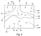
- the object 24 comprising the sample 15A and the bedding of the resin 15B is shown in a schematic illustration in Figure 3.
- Figure 3 shows a top view of the surface 21 (see Figure 1 ) of the object 24 comprising the sample 15A and the bedding of the resin 15B.
- Three areas of pieces of the sample 15A are partly visible (or shown) and are embedded in the resin 15B.
- the three areas of pieces are denoted with reference signs 15A', 15A" and 15A"'.
- the resin 15B fixes the three pieces 15A', 15A" and 15A"' of the sample 15A relative to the resin 15B and, therefore, ensures an easy handling and/or transport or arranging of the sample 15A on the sample carrier 14 of the charged particle beam device 1.
- the charged particle beam is generated in a further step S2 and is guided over an area of the object 24 comprising the sample 15A (i.e. over the pieces 15A', 15A" and 15A'" of the sample 15A) as well as the resin 15B so that the sample 15A and the resin 15B are scanned in a raster-like manner (step S3).
- Interaction radiation in the form of cathodoluminescence light is generated due to interaction of the charged particle beam with the sample 15A and the resin 15B.
- the cathodoluminescence light is detected using the first detector 17A (step S4).
- the resin 15B is a strong emitter of cathodoluminescence light as compared to the sample 15A to be analyzed.
- step S5 it is possible to identify the first area in which the resin 15B is arranged and second areas in which the pieces 15A', 15A" and 15A'" of the sample 15A are arranged. Therefore, in turn, it is possible to create a map including the position of the areas in which the sample 15A is located and the area in which the resin 15B is located.
- a step S6 is carried out after step S5 or in parallel to step S4.
- Step S6 comprises the step of generating interaction particles by interaction of the charged particle beam with the sample 15A (i.e. the pieces 15A', 15A" and 15A'" of the sample 15A) and the resin 15B.
- the interaction particles may be secondary particles (such as secondary electrons) and/or backscattered particles (such as backscattered electrons).
- the interaction particles are detected by using the second detector 17B.
- the second detector 17B generates signals which are used to record and/or display an image of the surface 21 of the scanned area of the object 24.
- particles, for example minerals which are included in the sample 15A (i.e.
- the pieces 15A', 15A" and 15A'" of the sample 15A) or in the resin 15B are identified using the image of the surface 21.
- the interaction of the charged particle beam with those particles generates a different signal in the second detector 17B than the rest of the sample 15A and the resin 15B. Therefore, it is possible to identify those particles in the image of the surface 21.
- Figure 3 shows several particles 22 in the form of minerals included in the pieces 15A', 15A" and 15A"' of the sample 15A.
- Figure 3 also shows several particles 23 in the form of minerals included in the resin 15B.
- step 5 provides for identifying the first area in which the resin 15B is arranged and second areas in which the pieces 15A', 15A" and 15A'" of the sample 15A are arranged.
- step 5 provides the position of the first area in which the resin 15B is arranged and of the second areas in which the pieces 15A', 15A" and 15A'" of the sample 15A are arranged. Therefore, it is now also possible to identify the position of the particles identified in step S7 in the pieces 15A', 15A" and 15A'" of the sample 15A or in the resin 17B.
- Step S8 provides now the step of analyzing the identified particles 22 or 23 using the third detector 17C.
- the charged particle beam is guided to the position of each particle 22 or 23 or is guided over the surface of each particle 22 or 23.
- the charged particle beam interacts with the particle 22 or 23.
- Interaction radiation in the form of X-rays is generated and is detected by using the third detector 17C.
- Signals of the third detector 17C are used for generating a spectrum for each particle 22 or 23 comprised in the resin 15B and/or in the sample 15A.
- the composition of at least one of the particles 22 or 23 comprised in the resin 15B and/or in the sample 15A is identified by analyzing the spectrum generated for this one particle 22 or 23.
- the shape, the size and the area of these identified particles 22 and 23 can be measured and stored for further analysis using the recorded and/or displayed images of the surface 21 of the scanned area of the object 24.
- Such data can be used to calculate the content of particles in the object 24, in the sample 15A or in the resin 15B, and in such a way, for example, the content of minerals in coal can be determined and arrangements can be made to reduce the negative side effects at a power plant during the combustion of such a type coal as discussed earlier.
- the charged particle beam device is an electron beam device.
- the charged particle beam device may also be an ion beam device.
- the ion beam device may comprise a charged particle source in the form of an ion source, in particular a gas field ion source.
- an electrostatic objective lens may be provided, the electrostatic objective lens comprising several electrodes biased with different electrostatic potentials and focusing the ion beam on the object 24.
- This electrostatic objective lens may comprise additional electrodes biased with electrical potentials to scan the ion beam perpendicularly to the optical axis of the objective lens across the surface of the object.
Description
- This application refers to a method of analyzing a sample using a charged particle beam device and to a charged particle beam device for analyzing a sample.
- It is often important to know the composition of materials used in different fields of technology. One of those materials is coal. Coal is, for example, one important source of global electricity production. In particular, coal is burned for providing energy to drive steam turbines which generate electricity. Coal mainly consists of carbon from plant material and naturally contains minerals. The mineral content of coal can be as high as 30% of the composition of coal. Minerals present in coal are, for example, silicate, clays, carbonates, oxides and sulphides. The exact quantities of the minerals in the coal may vary.
- The minerals in coal are often incombustible and cause negative side effects. In particular, they reduce the coal's heating value and end up as ash particulates which contribute to the reason for health problems in the form of asthma or bronchitis. Moreover, the ash which results from the combustion of minerals accumulates on heat-transfer surfaces of parts of a power plant. The ash has to be removed. Therefore, the ash results in an expensive down-time for maintenance of the power plant. Furthermore, the minerals also cause smog and produce nitrogen oxide as well as sulphur dioxide, which contribute to acid rain. Accordingly, it is desirable to get to know the accurate or detailed composition of coal.
- The composition of samples such as coal may be examined by using electron beam devices, in particular a scanning electron microscope (also called SEM) and/or a transmission electron microscope (also called TEM). Those electron beam devices are used for examining samples in order to obtain insights with regard to the properties and behaviour of said samples under specific conditions.
- In the case of a SEM, an electron beam (also called primary electron beam) is generated using a beam generator and focused by a beam guiding system, in particular an objective lens, onto a sample to be examined. Using a deflection device, the primary electron beam is guided in a raster-type fashion over a surface of the sample to be examined. In this case, the electrons of the primary electron beam interact with the material of the sample to be examined. As a consequence of the interaction, in particular electrons are emitted from the surface of the sample to be examined (so-called secondary electrons) and electrons of the primary electron beam are backscattered (so-called backscattered electrons). The secondary electrons and backscattered electrons are detected and used for image generation. Imaging of the surface of the sample to be examined is thus obtained.
- In the case of a TEM, a primary electron beam is likewise generated using a beam generator and focused by a beam guiding system onto a sample to be examined. The primary electron beam radiates through the sample to be examined. During the passage of the primary electron beam through the sample to be examined, the electrons of the primary electron beam interact with the material of the sample to be examined. The electrons passing through the sample to be examined are imaged onto a luminescence screen or onto a detector (for example a camera) by a system consisting of at least an objective lens and a projection lens system. In addition, electrons scattered or backscattered at the sample to be examined and/or secondary electrons emitted by the sample to be examined may be detected using further detectors in order to image the sample to be examined. In this case, the imaging is effected in the scanning mode of a TEM. A TEM of this type is generally designated as STEM.
- A charged particle beam guided onto a sample, for example an electron beam, can, in addition to the interaction particles mentioned above, also interact with the sample in such a way that electromagnetic radiation arises. For example, the electromagnetic radiation may be in the form of X-rays. These X-rays may be detected by using energy dispersive X-ray spectroscopy (so called EDX) which provides the composition of the sample by identifying the materials comprised in the sample. The electromagnetic radiation may also be in the form of cathodoluminescence light. By detecting and evaluating the cathodoluminescence light (for example using an intensity and spectral analysis), it is possible to determine properties of the material of the sample.
- It is known to use a SEM to analyze the composition of coal. For this purpose, a piece of coal is embedded in carnauba wax. The bedding made of carnauba wax fixes the position of the coal relative to the bedding made of carnauba wax. The coal and the bedding of carnauba wax are arranged on a sample holder which is introduced into the SEM. The use of carnauba wax may be problematic. It is known that arranging a sample in carnauba wax for examination with the SEM is not an easy process. Therefore, it often requires services of specialist laboratories which are expensive. Moreover, arranging the sample in carnauba wax is time consuming.
- A natural or synthetic resin could be used as a bedding for the coal instead of carnauba wax. Since resin is easier to handle, arranging of the coal in resin would not be as expensive as arranging in carnauba wax. However, the resin and coal have similar average atomic weights. This makes it nearly impossible to clearly distinguish the coal and the resin in a SEM by detecting backscattered electrons. Due to the similar atomic weights, the contrast in the image provided by detecting backscattered electrons for coal and resin is more or less equal. It is not possible to identify the coal and the resin in the image and to differentiate between the coal and the resin.
- With respect to the prior art, it is referred to
WO 2012/174173 A2 and to a publication with the title "Quantitative Cathodoluminescence Mapping with Application to a Kalgoorlie Scheelite" by Colin M. MacRae et al. in Microsc. Microanal. 15, 222-230, 2009. - Therefore, it is desirable to provide a method and a charged particle beam device which make it possible to use a bedding made of resin for examination of a sample, by using in particular backscattered electrons for imaging of the sample.
- According to the invention, this is solved by a method according to
claim 1. A computer readable medium storing computer software is given by the features ofclaim 6. A charged particle beam device according to the invention is given by the features ofclaim 7. Further features of the invention are evident from the following description, the following claims and/or the accompanying figures. - A method according to the invention is used for analyzing an object comprising a sample using a charged particle beam device. The term "object" will be explained further below. The sample may comprise a particle which is to be analyzed. In other words, the method is for operating the charged particle beam device in such a way that a sample is analyzed. The charged particle beam device comprises a charged particle source for generating a charged particle beam, an objective lens for focusing the charged particle beam onto the sample, a first detector for detecting interaction radiation and a second detector for detecting interaction particles. The method according to the invention comprises several steps. In particular, the method comprises the step of providing the object by arranging the sample in a resin, for example a natural resin or a synthetic resin such as a resin known as SpeciFix-20 offered by the company Struers A/S (catalogue number 40200048).Therefore, the object comprises the resin and the sample embedded in the resin. Moreover, the charged particle beam is generated by using the charged particle source. The method according to the invention also comprises the step of guiding the charged particle beam onto the sample and the resin using the objective lens. Thus, the charged particle beam is guided onto the sample and onto the resin. Furthermore, the charged particle beam is guided over the sample and the resin. For example, the charged particle beam is guided over the sample and the resin in a raster-like manner. The method according to the invention also comprises generating interaction radiation emitted from the sample and the resin due to an interaction of the charged particle beam with the sample as well as an interaction of the charged particle beam with the resin. Furthermore, the method according to the invention also comprises the step of identifying a first area in which the resin is arranged and identifying a second area in which the sample is arranged by detecting the interaction radiation using the first detector. Additionally, a position of at least one particle of the resin in the first area and/or at least one particle of the sample in the second area is identified by detecting interaction particles using the second detector. The interaction particles are generated by the interaction of the charged particle beam with the at least one particle of the resin or of the sample. For example, the interaction particles are emitted by the at least one particle (for example secondary electrons) or backscattered from the at least one particle (for example backscattered electrons). The at least one particle of the resin or of the sample is analyzed using the charged particle beam.
- The invention is not restricted to the order (sequence) of steps as mentioned above or mentioned further below. Alternatively, the order of the steps of the method according to the invention may be differently chosen with respect to one or more steps of the method according to the invention.
- The invention is based on the finding that it is possible to identify the first area in which the resin used as a bedding for the sample is arranged and the second area in which the sample is arranged, by detecting interaction radiation using the first detector. The term "area" is not restricted to a specific size. To the contrary, any area having any suitable size may be used. The resin is normally a strong emitter in interaction radiation as compared to the sample (for example coal). Therefore, it is possible to identify the second area in which the sample is arranged and the first area in which the resin is arranged, and to create a map including these areas. The map identifies the first area and the second area so that it is known at which position the resin is arranged and at which position the sample is arranged. Therefore, the charged particle beam may be guided to the second area in which the sample is arranged for further examination and analysis of the sample or a part of the sample to be analyzed, for example by detecting backscattered particles. This allows for identifying the areas in which, for example, minerals are included in the sample and to further analyze those minerals, for example by using EDX. However, the method can also be used for analyzing particles being included not in the sample, but in the resin.
- It is additionally or alternatively provided in an embodiment of the method according to the invention that the step of generating the interaction radiation comprises generating cathodoluminescence light. The resin, in particular the above mentioned kind of resins, is a strong emitter of cathodoluminescence light as compared to the sample to be analyzed. Therefore, it is possible to identify the first area in which the resin is arranged and the second area in which the sample is arranged.
- It is additionally or alternatively provided in a further embodiment of the method according to the invention that the step of analyzing the at least one particle of the resin or of the sample comprises detecting electromagnetic radiation (for example X-rays) by using, for example, a third detector. This embodiment comprises, for example, the analysis of the sample using EDX.
- It is additionally or alternatively provided in a further embodiment of the method according to the invention that the method comprises at least one of the following steps:
- In a first step, the charged particle beam is scanned over an object comprising the resin and the sample embedded in the resin. Interaction radiation, in particular cathodoluminescence light, is detected by using the first detector. Signals of the first detector are used for generating a first image based on the interaction radiation.
- In a second step, a first area of the object is identified or first areas of the object are identified which comprise(s) the resin by using the first detector detecting the interaction radiation.
- In a third step, a second area is identified or second areas of the object are identified which comprise(s) the sample embedded in the resin by using the first detector detecting the interaction radiation.
- In a fourth step, interaction particles generated by the interaction of the charged particle beam with the object (i.e. the resin and the sample embedded in the resin) are detected by using the second detector. The interaction particles may be secondary particles (such as secondary electrons) and/or backscattered particles (such as backscattered electrons). Signals generated by the second detector are used for generating a second image. In an embodiment of the method according to the invention, the fourth step and the first step are carried out in parallel.
- In a fifth step, the positions of particles comprised in the resin and/or in the sample are identified by analyzing the second image. The particles may be minerals. However, the invention is not restricted to the analysis of minerals. Instead, any kind of particle can be analyzed.
- In a sixth step, the particles comprised in the resin and/or in the sample are irradiated with the charged particle beam by guiding the charged particle beam to the identified positions of the particles. Interaction radiation (for example X-rays) is generated and detected using the third detector (for example, an EDX-detector). Signals of the third detector are used for generating a spectrum for each particle comprised in the resin and/or in the sample.
- In a seventh step, the composition of at least one of the particles comprised in the resin and/or in the sample is identified by analyzing the spectrum generated for this at least one particle. Furthermore, it is identified whether this one particle is arranged within the sample, at the surface of the sample or in the resin.
- The invention also refers to a computer readable medium storing computer software for analyzing an object using a charged particle beam device, the computer software comprising executable code which is run in a microprocessor. The method comprising at least one of the above or below mentioned steps or a combination of at least two of the above or below mentioned steps is carried out when the computer software is loaded in the microprocessor and the executable code is run in the microprocessor.
- The invention also refers to a charged particle beam device for analyzing an object. The charged particle beam device comprises a charged particle source for generating a charged particle beam, an objective lens for focusing the charged particle beam onto the object, a first detector for detecting interaction radiation, a second detector for detecting interaction particles, a microprocessor and a computer readable medium as mentioned above or below. The method comprising at least one of the above or below mentioned steps or a combination of at least two of the above or below mentioned steps is carried out when the computer software stored on the computer readable medium is loaded in the microprocessor and the executable code is run in the microprocessor.
- It is additionally or alternatively provided in an embodiment of the charged particle beam device according to the invention that the charged particle beam device is an electron beam device (for example a SEM). Alternatively, the charged particle beam device is an ion beam device.
- The invention is explained in greater detail below on the basis of exemplary embodiments and using figures, in which
- Figure 1
- shows a schematic illustration of an embodiment of the charged particle beam device according to the invention;
- Figure 1A
- shows a schematic illustration of a further embodiment of the charged particle beam device according to the invention;
- Figure 2
- shows a schematic illustration of a flowchart of an exemplary embodiment of the method according to the invention; and
- Figure 3
- shows an object of a sample to be analyzed and a resin.
-
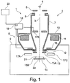
Figure 1 shows a schematic illustration of a chargedparticle beam device 1 in the form of a SEM comprising a chargedparticle beam column 2, which is embodied as an electron beam column. However, it is expressly pointed out that the invention is not restricted to a SEM. Rather, the invention can be used for any charged particle beam device, in particular for an ion beam device. - The charged
particle beam column 2 has anoptical axis 3, a beam generator 4 in the form of an electron source (cathode), afirst electrode 5 in the form of an extraction electrode, and asecond electrode 6 in the form of an anode, which simultaneously forms one end of abeam guiding tube 7. By way of example, the beam generator 4 is a thermal field emitter. Electrons that emerge from the beam generator 4 are accelerated to anode potential due to a potential difference between the beam generator 4 and thesecond electrode 6. Accordingly, a charged particle beam in the form of an electron beam is provided. - Furthermore, the charged
particle beam device 1 comprises anobjective lens 8, which projects into a sample chamber 9 of the chargedparticle beam device 1. Theobjective lens 8 has a hole through which thebeam guiding tube 7 is led. Theobjective lens 8 is furthermore provided withpole pieces 10, in which acoil 11 is arranged. An electrostatic retarding device is arranged downstream of thebeam guiding tube 7. Said electrostatic retarding device has atube electrode 12 forming one end of thebeam guiding tube 7. Furthermore, the electrostatic retarding device has asingle electrode 13 arranged adjacent to thetube electrode 12 along theoptical axis 3. Asample carrier 14 is arranged in the sample chamber 9. Thesample carrier 14 carries an object 24 (for example a block sample) comprising asample 15A to be examined and/or to be processed and a bedding made of aresin 15B. Thesample 15A is arranged in the bedding made of theresin 15B. - The
tube electrode 12 together with thebeam guiding tube 7 is at anode potential, while thesingle electrode 13 and theobject 24 comprising thesample 15A and the bedding made of theresin 15B are at a lower potential relative to the anode potential. In this way, the electrons of the charged particle beam can be decelerated to a desired energy required for the examination and/or processing of theobject 24 comprising thesample 15A and the bedding made of theresin 15B. The chargedparticle beam device 1 comprises afirst detector 17A for detecting cathodoluminescence light generated by an interaction of the charged particle beam with theobject 24 comprising thesample 15A and the bedding made of theresin 15B. The signals generated by thefirst detector 17A are communicated via a signal line (not shown) to anelectronic unit 18 comprising amicroprocessor 19, which is made for acquiring signals, for generating images of at least a part of theobject 24 and for transmitting the generated images to amonitor 20. Theelectronic unit 18 also comprises a computer readable medium storing computer software. The computer software comprises an executable code which is run in themicroprocessor 19. The method according to the invention is carried out when the executable code is run in themicroprocessor 19. - For imaging purposes, secondary electrons and/or backscattered electrons that arise on account of interactions of the charged particle beam with the
object 24 comprising thesample 15A and the bedding made of theresin 15B are detected by using asecond detector 17B arranged in thebeam guiding tube 7. Thesecond detector 17B is also connected with theelectronic unit 18 for communicating signals for imaging purposes. In an alternative embodiment thesecond detector 17B is arranged between thesingle electrode 13 and theobject 24, and thesecond detector 17B is used for detecting backscattered electrons. - The charged
particle beam device 1 also comprises athird detector 17C for detecting X-rays generated by an interaction of the charged particle beam with theobject 24 comprising thesample 15A and the bedding made of theresin 15B. Thethird detector 17C is used for material analysis using EDX and is connected with theelectronic unit 18 via a signal line (not shown) for communicating signals. - The charged
particle beam column 2 additionally comprises ascanning device 16, which deflects the charged particle beam, such that the charged particle beam can be scanned over theobject 24 comprising thesample 15A and the bedding made of theresin 15B arranged on thesample carrier 14. Thescanning device 16 is connected to theelectronic unit 18 and themicroprocessor 19 thereof for the purpose of controlling scanning of the charged particle beam over a (scanning) surface 21 of theobject 24 comprising thesample 15A and the bedding made of theresin 15B. - The
objective lens 8 focuses the charged particle beam onto thesurface 21 of theobject 24 comprising thesample 15A and the bedding made of theresin 15B. For this purpose, thecoil 11 of theobjective lens 8 is connected to theelectronic unit 18. Theelectronic unit 18 drives thecoil 11 and thus ensures that the charged particle beam is focused onto thesurface 21. -
Figure 1A shows a further schematic illustration of a chargedparticle beam device 1.Figure 1A is based onFigure 1 . Identical components are identified by identical reference signs. The chargedparticle beam device 1 is a SEM comprising a chargedparticle beam column 2 which is embodied as an electron beam column. The chargedparticle beam column 2 has anoptical axis 3, a beam generator 4A in the form of a cathode filament (electron source), a first electrode 5A in the form of a Wehnelt electrode and asecond electrode 6 in the form of an anode which is connected to the ground potential of theparticle beam device 1. The beam generator 4A is heated for emitting electrons. The electrons are accelerated due to a potential difference between the beam generator 4A and thesecond electrode 6. The first electrode 5A is negatively biased with respect to the potential of the beam generator 4A for controlling the current of the beam of electrons emitted from the beam generator 4A. Acondenser lens 25 is arranged between thesecond electrode 6 and theobjective lens 8. The embodiment shown inFigure 1A also comprises thefirst detector 17A, thesecond detector 17B and thethird detector 17C. However, thesecond detector 17B is now arranged at the side of the objective lens within the sample chamber. Moreover, the further two detectors, namely thefirst detector 17A and thethird detector 17C are arranged within the sample chamber. -
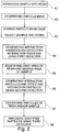
Figure 2 shows a schematic illustration of a flowchart of an exemplary embodiment of the method according to the invention. In a first step S1, thesample 15A is arranged in the bedding of theresin 15B such that the above mentionedobject 24 comprising thesample 15A and the bedding of theresin 15B is generated. Theobject 24 comprising thesample 15A and the bedding of theresin 15B is shown in a schematic illustration inFigure 3. Figure 3 shows a top view of the surface 21 (seeFigure 1 ) of theobject 24 comprising thesample 15A and the bedding of theresin 15B. Three areas of pieces of thesample 15A (for example three pieces of coal) are partly visible (or shown) and are embedded in theresin 15B. The three areas of pieces are denoted withreference signs 15A', 15A" and 15A"'. Theresin 15B fixes the threepieces 15A', 15A" and 15A"' of thesample 15A relative to theresin 15B and, therefore, ensures an easy handling and/or transport or arranging of thesample 15A on thesample carrier 14 of the chargedparticle beam device 1. - The charged particle beam is generated in a further step S2 and is guided over an area of the
object 24 comprising thesample 15A (i.e. over thepieces 15A', 15A" and 15A'" of thesample 15A) as well as theresin 15B so that thesample 15A and theresin 15B are scanned in a raster-like manner (step S3). Interaction radiation in the form of cathodoluminescence light is generated due to interaction of the charged particle beam with thesample 15A and theresin 15B. The cathodoluminescence light is detected using thefirst detector 17A (step S4). Theresin 15B is a strong emitter of cathodoluminescence light as compared to thesample 15A to be analyzed. Therefore, it is possible to identify the first area in which theresin 15B is arranged and second areas in which thepieces 15A', 15A" and 15A'" of thesample 15A are arranged (step S5). Therefore, in turn, it is possible to create a map including the position of the areas in which thesample 15A is located and the area in which theresin 15B is located. - A step S6 is carried out after step S5 or in parallel to step S4. Step S6 comprises the step of generating interaction particles by interaction of the charged particle beam with the
sample 15A (i.e. thepieces 15A', 15A" and 15A'" of thesample 15A) and theresin 15B. The interaction particles may be secondary particles (such as secondary electrons) and/or backscattered particles (such as backscattered electrons). The interaction particles are detected by using thesecond detector 17B. Thesecond detector 17B generates signals which are used to record and/or display an image of thesurface 21 of the scanned area of theobject 24. In a further step S7, particles, for example minerals, which are included in thesample 15A (i.e. thepieces 15A', 15A" and 15A'" of thesample 15A) or in theresin 15B are identified using the image of thesurface 21. The interaction of the charged particle beam with those particles generates a different signal in thesecond detector 17B than the rest of thesample 15A and theresin 15B. Therefore, it is possible to identify those particles in the image of thesurface 21.Figure 3 showsseveral particles 22 in the form of minerals included in thepieces 15A', 15A" and 15A"' of thesample 15A.Figure 3 also showsseveral particles 23 in the form of minerals included in theresin 15B. - As mentioned above,
step 5 provides for identifying the first area in which theresin 15B is arranged and second areas in which thepieces 15A', 15A" and 15A'" of thesample 15A are arranged. In other words,step 5 provides the position of the first area in which theresin 15B is arranged and of the second areas in which thepieces 15A', 15A" and 15A'" of thesample 15A are arranged. Therefore, it is now also possible to identify the position of the particles identified in step S7 in thepieces 15A', 15A" and 15A'" of thesample 15A or in theresin 17B. - Step S8 provides now the step of analyzing the identified
particles third detector 17C. The charged particle beam is guided to the position of eachparticle particle particle third detector 17C. Signals of thethird detector 17C are used for generating a spectrum for eachparticle resin 15B and/or in thesample 15A. The composition of at least one of theparticles resin 15B and/or in thesample 15A is identified by analyzing the spectrum generated for this oneparticle - In addition to the identification and analysis of the particles in
steps particles surface 21 of the scanned area of theobject 24. Such data can be used to calculate the content of particles in theobject 24, in thesample 15A or in theresin 15B, and in such a way, for example, the content of minerals in coal can be determined and arrangements can be made to reduce the negative side effects at a power plant during the combustion of such a type coal as discussed earlier. - The invention has been described with reference to the drawings for embodiments in which the charged particle beam device is an electron beam device. However, instead of an electron beam device, the charged particle beam device may also be an ion beam device. The ion beam device may comprise a charged particle source in the form of an ion source, in particular a gas field ion source. Additionally or alternatively to a magnetic objective lens, an electrostatic objective lens may be provided, the electrostatic objective lens comprising several electrodes biased with different electrostatic potentials and focusing the ion beam on the
object 24. This electrostatic objective lens may comprise additional electrodes biased with electrical potentials to scan the ion beam perpendicularly to the optical axis of the objective lens across the surface of the object. - The features of the invention disclosed in the description, the figures and/or the claims may be essential either individually or in any combination for the realisation of the invention in its different embodiments.
-
- 1
- charged particle beam device
- 2
- charged particle beam column
- 3
- optical axis
- 4
- beam generator (thermal field emitter)
- 4A
- beam generator (cathode filament)
- 5
- first electrode (extraction electrode)
- 5A
- first electrode (Wehnelt electrode)
- 6
- second electrode (anode)
- 7
- beam guiding tube
- 8
- objective lens
- 9
- sample chamber
- 10
- pole pieces
- 11
- coil
- 12
- tube electrode
- 13
- single electrode
- 14
- sample carrier
- 15A
- sample
- 15A'
- first piece of sample
- 15A"
- second piece of sample
- 15A"'
- third piece of sample
- 15B
- resin
- 16
- scanning device
- 17A
- first detector
- 17B
- second detector
- 17C
- third detector
- 18
- electronic unit
- 19
- microprocessor
- 20
- monitor
- 21
- surface
- 22
- minerals in sample
- 23
- minerals in resin
- 24
- object
- 25
- condenser lens
Claims (8)
- Method of analyzing an object (24) using a charged particle beam device (1),- the charged particle beam device (1) comprising a charged particle source (4) for generating a charged particle beam, an objective lens (8) for focusing the charged particle beam onto the object (24), a first detector (17A) for detecting interaction radiation and a second detector (17B) for detecting interaction particles,wherein the method comprises the following steps:- providing the object (24) comprising a sample (15A, 15A', 15A", 15A'") and a resin (15B) by arranging the sample (15A, 15A', 15A", 15A'") in the resin (15B);- generating the charged particle beam using the charged particle source (4);- guiding the charged particle beam onto the sample (15A, 15A', 15A", 15A"') and the resin (15B) using the objective lens (8);- guiding the charged particle beam over the sample (15A, 15A', 15A", 15A"') and the resin (15B);- generating interaction radiation emitted from the sample (15A, 15A', 15A", 15A"') and the resin (15B) due to interaction of the charged particle beam with the sample (15A, 15A', 15A", 15A"') as well as interaction of the charged particle beam with the resin (15B);- identifying a first area in which the resin (15B) is arranged and identifying a second area in which the sample (15A, 15A', 15A", 15A"') is arranged by detecting the interaction radiation using the first detector (17A);- identifying a position of at least one particle of the resin (15B) in the first area or at least one particle of the sample (15A, 15A', 15A", 15A"') in the second area by detecting interaction particles using the second detector (17B) wherein the interaction particles are generated by the interaction of the charged particle beam with the at least one particle of the resin (15B) or of the sample (15A, 15A', 15A", 15A"'); and- analyzing the at least one particle of the resin (15B) or of the sample (15A, 15A', 15A", 15A"') using the charged particle beam.
- The method of claim 1, wherein generating the interaction radiation comprises generating cathodoluminescence light.
- The method of claim 1 or 2, wherein analyzing the at least one particle of the resin (15B) or the sample (15A, 15A', 15A", 15A"') comprises detecting the interaction particles using the second detector (17B).
- The method of claim 3, wherein detecting the interaction particles comprises detecting interaction particles emitted by the sample (15A, 15A', 15A", 15A"') or backscattered from the sample (15A, 15A', 15A", 15A'").
- The method of one of the preceding claims, wherein analyzing the sample (15A, 15A', 15A", 15A"') comprises at least one of: detecting electromagnetic radiation and detecting electromagnetic radiation in the form of X-rays.
- A computer readable medium storing computer software for analyzing an object (24) using a charged particle beam device (1), the computer software comprising executable code which is runnable in a microprocessor (19), wherein the method according to one of the preceding claims is carried out when the computer software is loaded in the microprocessor (19) and the executable code is run in the microprocessor (19).
- A charged particle beam device (1) for analyzing an object (24), the charged particle beam device (1) comprising:- a charged particle source (4) for generating a charged particle beam,- an objective lens (8) for focusing the charged particle beam onto the object (24),- a first detector (17A) for detecting interaction radiation;- a second detector (17B) for detecting interaction particles,- a microprocessor (19); and- a computer readable medium according to claim 6, wherein the executable code is runnable in said microprocessor (19).
- The charged particle beam device (1) according to claim 7, wherein- the charged particle beam device (1) is an electron beam device; or- the charged particle beam device (1) is an ion beam device.
Priority Applications (4)
| Application Number | Priority Date | Filing Date | Title |
|---|---|---|---|
| EP13151344.2A EP2755021B1 (en) | 2013-01-15 | 2013-01-15 | Method of analyzing a sample and charged particle beam device for analyzing a sample |
| US14/150,012 US9159532B2 (en) | 2013-01-15 | 2014-01-08 | Method of analyzing a sample and charged particle beam device for analyzing a sample |
| IN65DE2014 IN2014DE00065A (en) | 2013-01-15 | 2014-01-09 | |
| CN201410017457.3A CN104089966B (en) | 2013-01-15 | 2014-01-15 | Analyze method, the charged particle beam apparatus and computer-readable medium for analyzing sample of sample |
Applications Claiming Priority (1)
| Application Number | Priority Date | Filing Date | Title |
|---|---|---|---|
| EP13151344.2A EP2755021B1 (en) | 2013-01-15 | 2013-01-15 | Method of analyzing a sample and charged particle beam device for analyzing a sample |
Publications (2)
| Publication Number | Publication Date |
|---|---|
| EP2755021A1 EP2755021A1 (en) | 2014-07-16 |
| EP2755021B1 true EP2755021B1 (en) | 2016-06-22 |
Family
ID=47563221
Family Applications (1)
| Application Number | Title | Priority Date | Filing Date |
|---|---|---|---|
| EP13151344.2A Active EP2755021B1 (en) | 2013-01-15 | 2013-01-15 | Method of analyzing a sample and charged particle beam device for analyzing a sample |
Country Status (4)
| Country | Link |
|---|---|
| US (1) | US9159532B2 (en) |
| EP (1) | EP2755021B1 (en) |
| CN (1) | CN104089966B (en) |
| IN (1) | IN2014DE00065A (en) |
Families Citing this family (10)
| Publication number | Priority date | Publication date | Assignee | Title |
|---|---|---|---|---|
| US9190241B2 (en) * | 2013-03-25 | 2015-11-17 | Hermes-Microvision, Inc. | Charged particle beam apparatus |
| JP6689602B2 (en) * | 2014-12-22 | 2020-04-28 | カール ツァイス マイクロスコーピー エルエルシー | Charged particle beam system and method |
| US10236156B2 (en) | 2015-03-25 | 2019-03-19 | Hermes Microvision Inc. | Apparatus of plural charged-particle beams |
| JP7045371B2 (en) * | 2017-06-05 | 2022-03-31 | フォンダチオーネ ブルーノ ケスラー | Radiation detector and radiation detector |
| CN107727677A (en) * | 2017-09-22 | 2018-02-23 | 中国科学院地质与地球物理研究所 | The cathodoluminescence imaging method of monazite |
| WO2019224896A1 (en) * | 2018-05-22 | 2019-11-28 | 株式会社日立ハイテクノロジーズ | Charged particle beam device and detector position adjustment method for charged particle beam device |
| CN110376229B (en) * | 2019-06-12 | 2020-09-04 | 聚束科技(北京)有限公司 | Scanning electron microscope with combined detection system and sample detection method |
| DE102019208661A1 (en) * | 2019-06-13 | 2020-12-17 | Carl Zeiss Microscopy Gmbh | Method for operating a particle beam device and particle beam device for carrying out the method |
| US11114274B2 (en) * | 2019-12-23 | 2021-09-07 | Carl Zeiss Smt Gmbh | Method and system for testing an integrated circuit |
| US11257657B2 (en) * | 2020-02-18 | 2022-02-22 | ICT Integrated Circuit Testing Gesellschaft für Halbleiterprüftechnik mbH | Charged particle beam device with interferometer for height measurement |
Family Cites Families (9)
| Publication number | Priority date | Publication date | Assignee | Title |
|---|---|---|---|---|
| JP3834495B2 (en) * | 2001-09-27 | 2006-10-18 | 株式会社東芝 | Fine pattern inspection apparatus, CD-SEM apparatus management apparatus, fine pattern inspection method, CD-SEM apparatus management method, program, and computer-readable recording medium |
| AU2003279904A1 (en) * | 2002-10-08 | 2004-05-04 | Applied Materials Israel, Ltd. | Methods and systems for process monitoring using x-ray emission |
| CN1820346B (en) * | 2003-05-09 | 2011-01-19 | 株式会社荏原制作所 | Testing apparatus using charged particles and device manufacturing method using the testing apparatus |
| JP4283201B2 (en) * | 2004-10-14 | 2009-06-24 | 株式会社荏原製作所 | Information recording medium inspection apparatus and method |
| JP4636897B2 (en) * | 2005-02-18 | 2011-02-23 | 株式会社日立ハイテクサイエンスシステムズ | Scanning electron microscope |
| EP2388796A1 (en) * | 2010-05-21 | 2011-11-23 | FEI Company | Simultaneous electron detection |
| BR112013020554A2 (en) | 2011-02-28 | 2020-07-28 | Prad Research And Development Limited | method for building a model of a sample of porous media, system for building a model of a sample of porous media, and methods for segmenting a digital image of porous media |
| WO2012174173A2 (en) * | 2011-06-13 | 2012-12-20 | President And Fellows Of Harvard College | Multi-color nanoscale imaging based on nanoparticle cathodoluminescence |
| DE102012217761B4 (en) * | 2012-09-28 | 2020-02-06 | Carl Zeiss Microscopy Gmbh | Process for avoiding artifacts in serial block face imaging |
-
2013
- 2013-01-15 EP EP13151344.2A patent/EP2755021B1/en active Active
-
2014
- 2014-01-08 US US14/150,012 patent/US9159532B2/en active Active
- 2014-01-09 IN IN65DE2014 patent/IN2014DE00065A/en unknown
- 2014-01-15 CN CN201410017457.3A patent/CN104089966B/en active Active
Also Published As
| Publication number | Publication date |
|---|---|
| EP2755021A1 (en) | 2014-07-16 |
| IN2014DE00065A (en) | 2015-06-19 |
| CN104089966A (en) | 2014-10-08 |
| US9159532B2 (en) | 2015-10-13 |
| US20140197310A1 (en) | 2014-07-17 |
| CN104089966B (en) | 2018-07-27 |
Similar Documents
| Publication | Publication Date | Title |
|---|---|---|
| EP2755021B1 (en) | Method of analyzing a sample and charged particle beam device for analyzing a sample | |
| Tamborini et al. | Application of secondary ion mass spectrometry to the identification of single particles of uranium and their isotopic measurement | |
| US8664595B2 (en) | Cluster analysis of unknowns in SEM-EDS dataset | |
| US9778215B2 (en) | Automated mineral classification | |
| US9535020B2 (en) | Analyzing an object using a particle beam apparatus | |
| EP2511937A1 (en) | Electron microscope | |
| US9620331B1 (en) | Method for analyzing an object and charged particle beam device for carrying out the method | |
| KR20200021401A (en) | Method of examining a sample using a charged particle microscope | |
| Sisco et al. | Evaluation of C60 secondary ion mass spectrometry for the chemical analysis and imaging of fingerprints | |
| CN108538693A (en) | The aberration measurement of charged particle microscope | |
| US9355814B2 (en) | Charged particle beam apparatus | |
| KR20130135541A (en) | Scanning electron microscope | |
| Cik et al. | Field emission scanning electron microscope (fesem) facility in bti | |
| Notte et al. | An Introduction to Helium Ion Microscopy and its Nanotechnology Applications | |
| JP6385443B2 (en) | Notched magnetic lens for improved sample access in SEM | |
| EP3203494A1 (en) | Energy-discrimination electron detector and scanning electron microscope in which same is used | |
| JP7030035B2 (en) | Evaluation method of unevenness of element distribution and charged particle beam device | |
| US20170345616A1 (en) | Systems and methods for adaptive scanning | |
| JP5851256B2 (en) | Electron beam equipment | |
| McKee et al. | Proton microprobes and their applications | |
| Zhao | SEM-EDX Analysis of Aerosol Samples | |
| JP2023051853A (en) | Method and system for element mapping | |
| Arkens et al. | Structural Characteristics of Metals and Ceramics | |
| Mullerova et al. | Multi-Channel Detection of the Angular Distribution of Backscattered Electrons in the Scanning Low Energy Electron Microscope | |
| Botton | Principles of Electron Energy Loss |
Legal Events
| Date | Code | Title | Description |
|---|---|---|---|
| PUAI | Public reference made under article 153(3) epc to a published international application that has entered the european phase |
Free format text: ORIGINAL CODE: 0009012 |
|
| 17P | Request for examination filed |
Effective date: 20130115 |
|
| AK | Designated contracting states |
Kind code of ref document: A1 Designated state(s): AL AT BE BG CH CY CZ DE DK EE ES FI FR GB GR HR HU IE IS IT LI LT LU LV MC MK MT NL NO PL PT RO RS SE SI SK SM TR |
|
| AX | Request for extension of the european patent |
Extension state: BA ME |
|
| R17P | Request for examination filed (corrected) |
Effective date: 20150114 |
|
| RBV | Designated contracting states (corrected) |
Designated state(s): AL AT BE BG CH CY CZ DE DK EE ES FI FR GB GR HR HU IE IS IT LI LT LU LV MC MK MT NL NO PL PT RO RS SE SI SK SM TR |
|
| GRAP | Despatch of communication of intention to grant a patent |
Free format text: ORIGINAL CODE: EPIDOSNIGR1 |
|
| INTG | Intention to grant announced |
Effective date: 20150707 |
|
| INTG | Intention to grant announced |
Effective date: 20151203 |
|
| GRAS | Grant fee paid |
Free format text: ORIGINAL CODE: EPIDOSNIGR3 |
|
| GRAA | (expected) grant |
Free format text: ORIGINAL CODE: 0009210 |
|
| AK | Designated contracting states |
Kind code of ref document: B1 Designated state(s): AL AT BE BG CH CY CZ DE DK EE ES FI FR GB GR HR HU IE IS IT LI LT LU LV MC MK MT NL NO PL PT RO RS SE SI SK SM TR |
|
| REG | Reference to a national code |
Ref country code: GB Ref legal event code: FG4D |
|
| REG | Reference to a national code |
Ref country code: CH Ref legal event code: EP |
|
| REG | Reference to a national code |
Ref country code: IE Ref legal event code: FG4D |
|
| REG | Reference to a national code |
Ref country code: AT Ref legal event code: REF Ref document number: 807948 Country of ref document: AT Kind code of ref document: T Effective date: 20160715 |
|
| REG | Reference to a national code |
Ref country code: DE Ref legal event code: R096 Ref document number: 602013008683 Country of ref document: DE |
|
| REG | Reference to a national code |
Ref country code: NL Ref legal event code: FP |
|
| REG | Reference to a national code |
Ref country code: LT Ref legal event code: MG4D |
|
| PG25 | Lapsed in a contracting state [announced via postgrant information from national office to epo] |
Ref country code: LT Free format text: LAPSE BECAUSE OF FAILURE TO SUBMIT A TRANSLATION OF THE DESCRIPTION OR TO PAY THE FEE WITHIN THE PRESCRIBED TIME-LIMIT Effective date: 20160622 Ref country code: NO Free format text: LAPSE BECAUSE OF FAILURE TO SUBMIT A TRANSLATION OF THE DESCRIPTION OR TO PAY THE FEE WITHIN THE PRESCRIBED TIME-LIMIT Effective date: 20160922 Ref country code: FI Free format text: LAPSE BECAUSE OF FAILURE TO SUBMIT A TRANSLATION OF THE DESCRIPTION OR TO PAY THE FEE WITHIN THE PRESCRIBED TIME-LIMIT Effective date: 20160622 |
|
| REG | Reference to a national code |
Ref country code: AT Ref legal event code: MK05 Ref document number: 807948 Country of ref document: AT Kind code of ref document: T Effective date: 20160622 |
|
| PG25 | Lapsed in a contracting state [announced via postgrant information from national office to epo] |
Ref country code: SE Free format text: LAPSE BECAUSE OF FAILURE TO SUBMIT A TRANSLATION OF THE DESCRIPTION OR TO PAY THE FEE WITHIN THE PRESCRIBED TIME-LIMIT Effective date: 20160622 Ref country code: GR Free format text: LAPSE BECAUSE OF FAILURE TO SUBMIT A TRANSLATION OF THE DESCRIPTION OR TO PAY THE FEE WITHIN THE PRESCRIBED TIME-LIMIT Effective date: 20160923 Ref country code: LV Free format text: LAPSE BECAUSE OF FAILURE TO SUBMIT A TRANSLATION OF THE DESCRIPTION OR TO PAY THE FEE WITHIN THE PRESCRIBED TIME-LIMIT Effective date: 20160622 Ref country code: RS Free format text: LAPSE BECAUSE OF FAILURE TO SUBMIT A TRANSLATION OF THE DESCRIPTION OR TO PAY THE FEE WITHIN THE PRESCRIBED TIME-LIMIT Effective date: 20160622 Ref country code: HR Free format text: LAPSE BECAUSE OF FAILURE TO SUBMIT A TRANSLATION OF THE DESCRIPTION OR TO PAY THE FEE WITHIN THE PRESCRIBED TIME-LIMIT Effective date: 20160622 |
|
| PG25 | Lapsed in a contracting state [announced via postgrant information from national office to epo] |
Ref country code: RO Free format text: LAPSE BECAUSE OF FAILURE TO SUBMIT A TRANSLATION OF THE DESCRIPTION OR TO PAY THE FEE WITHIN THE PRESCRIBED TIME-LIMIT Effective date: 20160622 Ref country code: EE Free format text: LAPSE BECAUSE OF FAILURE TO SUBMIT A TRANSLATION OF THE DESCRIPTION OR TO PAY THE FEE WITHIN THE PRESCRIBED TIME-LIMIT Effective date: 20160622 Ref country code: IS Free format text: LAPSE BECAUSE OF FAILURE TO SUBMIT A TRANSLATION OF THE DESCRIPTION OR TO PAY THE FEE WITHIN THE PRESCRIBED TIME-LIMIT Effective date: 20161022 Ref country code: IT Free format text: LAPSE BECAUSE OF FAILURE TO SUBMIT A TRANSLATION OF THE DESCRIPTION OR TO PAY THE FEE WITHIN THE PRESCRIBED TIME-LIMIT Effective date: 20160622 Ref country code: SK Free format text: LAPSE BECAUSE OF FAILURE TO SUBMIT A TRANSLATION OF THE DESCRIPTION OR TO PAY THE FEE WITHIN THE PRESCRIBED TIME-LIMIT Effective date: 20160622 |
|
| PG25 | Lapsed in a contracting state [announced via postgrant information from national office to epo] |
Ref country code: PT Free format text: LAPSE BECAUSE OF FAILURE TO SUBMIT A TRANSLATION OF THE DESCRIPTION OR TO PAY THE FEE WITHIN THE PRESCRIBED TIME-LIMIT Effective date: 20161024 Ref country code: BE Free format text: LAPSE BECAUSE OF FAILURE TO SUBMIT A TRANSLATION OF THE DESCRIPTION OR TO PAY THE FEE WITHIN THE PRESCRIBED TIME-LIMIT Effective date: 20160622 Ref country code: PL Free format text: LAPSE BECAUSE OF FAILURE TO SUBMIT A TRANSLATION OF THE DESCRIPTION OR TO PAY THE FEE WITHIN THE PRESCRIBED TIME-LIMIT Effective date: 20160622 Ref country code: ES Free format text: LAPSE BECAUSE OF FAILURE TO SUBMIT A TRANSLATION OF THE DESCRIPTION OR TO PAY THE FEE WITHIN THE PRESCRIBED TIME-LIMIT Effective date: 20160622 Ref country code: SM Free format text: LAPSE BECAUSE OF FAILURE TO SUBMIT A TRANSLATION OF THE DESCRIPTION OR TO PAY THE FEE WITHIN THE PRESCRIBED TIME-LIMIT Effective date: 20160622 Ref country code: AT Free format text: LAPSE BECAUSE OF FAILURE TO SUBMIT A TRANSLATION OF THE DESCRIPTION OR TO PAY THE FEE WITHIN THE PRESCRIBED TIME-LIMIT Effective date: 20160622 |
|
| REG | Reference to a national code |
Ref country code: DE Ref legal event code: R097 Ref document number: 602013008683 Country of ref document: DE |
|
| PLBE | No opposition filed within time limit |
Free format text: ORIGINAL CODE: 0009261 |
|
| STAA | Information on the status of an ep patent application or granted ep patent |
Free format text: STATUS: NO OPPOSITION FILED WITHIN TIME LIMIT |
|
| 26N | No opposition filed |
Effective date: 20170323 |
|
| PG25 | Lapsed in a contracting state [announced via postgrant information from national office to epo] |
Ref country code: DK Free format text: LAPSE BECAUSE OF FAILURE TO SUBMIT A TRANSLATION OF THE DESCRIPTION OR TO PAY THE FEE WITHIN THE PRESCRIBED TIME-LIMIT Effective date: 20160622 |
|
| PG25 | Lapsed in a contracting state [announced via postgrant information from national office to epo] |
Ref country code: SI Free format text: LAPSE BECAUSE OF FAILURE TO SUBMIT A TRANSLATION OF THE DESCRIPTION OR TO PAY THE FEE WITHIN THE PRESCRIBED TIME-LIMIT Effective date: 20160622 |
|
| REG | Reference to a national code |
Ref country code: CH Ref legal event code: PL |
|
| GBPC | Gb: european patent ceased through non-payment of renewal fee |
Effective date: 20170115 |
|
| PG25 | Lapsed in a contracting state [announced via postgrant information from national office to epo] |
Ref country code: MC Free format text: LAPSE BECAUSE OF FAILURE TO SUBMIT A TRANSLATION OF THE DESCRIPTION OR TO PAY THE FEE WITHIN THE PRESCRIBED TIME-LIMIT Effective date: 20160622 |
|
| REG | Reference to a national code |
Ref country code: FR Ref legal event code: ST Effective date: 20170929 |
|
| PG25 | Lapsed in a contracting state [announced via postgrant information from national office to epo] |
Ref country code: LI Free format text: LAPSE BECAUSE OF NON-PAYMENT OF DUE FEES Effective date: 20170131 Ref country code: FR Free format text: LAPSE BECAUSE OF NON-PAYMENT OF DUE FEES Effective date: 20170131 Ref country code: CH Free format text: LAPSE BECAUSE OF NON-PAYMENT OF DUE FEES Effective date: 20170131 |
|
| REG | Reference to a national code |
Ref country code: IE Ref legal event code: MM4A |
|
| PG25 | Lapsed in a contracting state [announced via postgrant information from national office to epo] |
Ref country code: LU Free format text: LAPSE BECAUSE OF NON-PAYMENT OF DUE FEES Effective date: 20170115 Ref country code: GB Free format text: LAPSE BECAUSE OF NON-PAYMENT OF DUE FEES Effective date: 20170115 |
|
| PG25 | Lapsed in a contracting state [announced via postgrant information from national office to epo] |
Ref country code: IE Free format text: LAPSE BECAUSE OF NON-PAYMENT OF DUE FEES Effective date: 20170115 |
|
| PG25 | Lapsed in a contracting state [announced via postgrant information from national office to epo] |
Ref country code: MT Free format text: LAPSE BECAUSE OF NON-PAYMENT OF DUE FEES Effective date: 20170115 |
|
| PG25 | Lapsed in a contracting state [announced via postgrant information from national office to epo] |
Ref country code: AL Free format text: LAPSE BECAUSE OF FAILURE TO SUBMIT A TRANSLATION OF THE DESCRIPTION OR TO PAY THE FEE WITHIN THE PRESCRIBED TIME-LIMIT Effective date: 20160622 |
|
| PG25 | Lapsed in a contracting state [announced via postgrant information from national office to epo] |
Ref country code: HU Free format text: LAPSE BECAUSE OF FAILURE TO SUBMIT A TRANSLATION OF THE DESCRIPTION OR TO PAY THE FEE WITHIN THE PRESCRIBED TIME-LIMIT; INVALID AB INITIO Effective date: 20130115 |
|
| PG25 | Lapsed in a contracting state [announced via postgrant information from national office to epo] |
Ref country code: BG Free format text: LAPSE BECAUSE OF FAILURE TO SUBMIT A TRANSLATION OF THE DESCRIPTION OR TO PAY THE FEE WITHIN THE PRESCRIBED TIME-LIMIT Effective date: 20160622 |
|
| PG25 | Lapsed in a contracting state [announced via postgrant information from national office to epo] |
Ref country code: CY Free format text: LAPSE BECAUSE OF NON-PAYMENT OF DUE FEES Effective date: 20160622 |
|
| PG25 | Lapsed in a contracting state [announced via postgrant information from national office to epo] |
Ref country code: MK Free format text: LAPSE BECAUSE OF FAILURE TO SUBMIT A TRANSLATION OF THE DESCRIPTION OR TO PAY THE FEE WITHIN THE PRESCRIBED TIME-LIMIT Effective date: 20160622 |
|
| PG25 | Lapsed in a contracting state [announced via postgrant information from national office to epo] |
Ref country code: TR Free format text: LAPSE BECAUSE OF FAILURE TO SUBMIT A TRANSLATION OF THE DESCRIPTION OR TO PAY THE FEE WITHIN THE PRESCRIBED TIME-LIMIT Effective date: 20160622 |
|
| PGFP | Annual fee paid to national office [announced via postgrant information from national office to epo] |
Ref country code: NL Payment date: 20220119 Year of fee payment: 10 |
|
| PGFP | Annual fee paid to national office [announced via postgrant information from national office to epo] |
Ref country code: CZ Payment date: 20230106 Year of fee payment: 11 |
|
| PGFP | Annual fee paid to national office [announced via postgrant information from national office to epo] |
Ref country code: DE Payment date: 20230123 Year of fee payment: 11 |
|
| REG | Reference to a national code |
Ref country code: NL Ref legal event code: MM Effective date: 20230201 |
|
| PG25 | Lapsed in a contracting state [announced via postgrant information from national office to epo] |
Ref country code: NL Free format text: LAPSE BECAUSE OF NON-PAYMENT OF DUE FEES Effective date: 20230201 |