EP2754872A2 - Engine-generator with improved efficiency and low noise - Google Patents
Engine-generator with improved efficiency and low noise Download PDFInfo
- Publication number
- EP2754872A2 EP2754872A2 EP13425121.4A EP13425121A EP2754872A2 EP 2754872 A2 EP2754872 A2 EP 2754872A2 EP 13425121 A EP13425121 A EP 13425121A EP 2754872 A2 EP2754872 A2 EP 2754872A2
- Authority
- EP
- European Patent Office
- Prior art keywords
- engine
- radiator
- engine generator
- electro
- fans
- Prior art date
- Legal status (The legal status is an assumption and is not a legal conclusion. Google has not performed a legal analysis and makes no representation as to the accuracy of the status listed.)
- Granted
Links
Images





Classifications
-
- F—MECHANICAL ENGINEERING; LIGHTING; HEATING; WEAPONS; BLASTING
- F01—MACHINES OR ENGINES IN GENERAL; ENGINE PLANTS IN GENERAL; STEAM ENGINES
- F01P—COOLING OF MACHINES OR ENGINES IN GENERAL; COOLING OF INTERNAL-COMBUSTION ENGINES
- F01P7/00—Controlling of coolant flow
- F01P7/02—Controlling of coolant flow the coolant being cooling-air
-
- F—MECHANICAL ENGINEERING; LIGHTING; HEATING; WEAPONS; BLASTING
- F02—COMBUSTION ENGINES; HOT-GAS OR COMBUSTION-PRODUCT ENGINE PLANTS
- F02B—INTERNAL-COMBUSTION PISTON ENGINES; COMBUSTION ENGINES IN GENERAL
- F02B63/00—Adaptations of engines for driving pumps, hand-held tools or electric generators; Portable combinations of engines with engine-driven devices
- F02B63/04—Adaptations of engines for driving pumps, hand-held tools or electric generators; Portable combinations of engines with engine-driven devices for electric generators
- F02B63/044—Adaptations of engines for driving pumps, hand-held tools or electric generators; Portable combinations of engines with engine-driven devices for electric generators the engine-generator unit being placed on a frame or in an housing
-
- F—MECHANICAL ENGINEERING; LIGHTING; HEATING; WEAPONS; BLASTING
- F01—MACHINES OR ENGINES IN GENERAL; ENGINE PLANTS IN GENERAL; STEAM ENGINES
- F01P—COOLING OF MACHINES OR ENGINES IN GENERAL; COOLING OF INTERNAL-COMBUSTION ENGINES
- F01P2025/00—Measuring
- F01P2025/08—Temperature
- F01P2025/13—Ambient temperature
-
- F—MECHANICAL ENGINEERING; LIGHTING; HEATING; WEAPONS; BLASTING
- F01—MACHINES OR ENGINES IN GENERAL; ENGINE PLANTS IN GENERAL; STEAM ENGINES
- F01P—COOLING OF MACHINES OR ENGINES IN GENERAL; COOLING OF INTERNAL-COMBUSTION ENGINES
- F01P2025/00—Measuring
- F01P2025/60—Operating parameters
- F01P2025/62—Load
Definitions
- the present invention relates to an engine generator with improved efficiency and quiet operation.
- the invention relates to an engine generator of the type mentioned, apparently equal to those in commerce and in use at present with regard to the use and part of the components but profoundly different in philosophy, in conception and operation.
- An engine generator is in fact a machine capable of generating electrical energy from combustion thermal energy (passing through an intermediate conversion to mechanical energy) formed by a heat engine coupled to an electric generator (alternator).
- a feature of overriding importance of engine generators is therefore the need to maintain a stable output frequency, also when the applied electrical load varies. To this end, regardless of the electrical load applied, the thermal engine of an engine generator has to work at constant speed.
- the heat engine then generates a greater or lesser amount of heat.
- the cooling is achieved by using a hydraulic circuit of cooling, the cooling liquid being cooled in a radiator invested by a constant airflow, the same air also investing the engine generator.
- the required amount of cooling air is determined when designing the generator in order to ensure proper cooling in the conditions of maximum demand of heat dissipation.
- the greater or lesser demand for heat dissipation is satisfied by adjusting the amount of cooling fluid circulating in the cooling circuit, or its speed.
- the airflow for cooling enters the side where the alternator is positioned and exits at 90% from the opposite side (area in which is located a radiator devoted to the heat exchange between the air and the cooling fluid of the engine generator) and the remaining 10% exits from discharges of combustion gases. It follows that almost all of the air used for cooling passes from the area of the engine/alternator to that of the radiator.
- the radiator used for the disposal of excess heat is equipped with a fan working at 1500/1800 rounds/min depending on the engine generator works at 50 Hz or 60 Hz. This fan is mechanically connected to the shaft of the engine, hence ensuring its functioning at fixed speed.
- the speed of the fan being fixed, the airflow is dimensioned to cope with the extreme conditions of use (generally 50 degrees of ambient temperature and 110% of the electrical load), and the temperature of the engine is adjusted by regulating the cooling liquid flow by means of a thermostatic valve, which opens progressively with increasing temperature of the cooling liquid, allowing a greater amount of liquid to exchange heat with the air in the radiator.
- the absorption of passive energy, in these cases, is always maximum and constant, even when the conditions of use does not require it.
- an engine generator of 1000kW of known type has a mechanical fan that absorbs approximately 40kW of power, equal to 4% of the maximum power, and is sized to move a flow of air of 1,6 m 3 /s. This flow is required to dispose of the overheating of the engine at an ambient temperature of 50 °C and operating conditions equal to 110% of the design electrical load. In every moment of the useful life of the engine generator when there are no such conditions, cooling it would be possible with a smaller mass of air, the movement of which requiring less energy, but it does not. Assuming a normal condition of use of an engine generator, in PRP applications as defined by ISO 8528, the average electrical load does not exceed 50% of the nominal power and average temperatures never exceed 25 °C. Under these conditions, 35 kW saved on average 500kW produced would result in a fuel savings of around 7%.
- the purpose of the present invention is therefore to provide an engine generator with improved efficiency and quietness which allows to overcome the limitations of the solutions of thepriorart and to axhieve the technical results previously described.
- said engine generator can be realized with substantially reduced costs, both with regard to production costs and with regard to the management costs.
- Not least object of the invention is to provide an engine generator with improved efficiency and low noise that is substantially simple, safe, reliable and environmentally friendly.
- an engine generator with improved efficiency and low noise comprising an engine and an alternator, housed inside a casing, as well as a cooling system based on a cooling fluid in turn cooled in a radiator in which the radiating surface of said radiator is invested by an airflow conveyed by one or more fans, where the flow of the cooling fluid is constant and the airflow is variable.
- said radiator is an electro radiator with one or more fans with variable speed, controlled through a system of sensors and solenoid valves, managed by a control and manage unit, in order to regulate the airflow on the basis of the actual use condition depending on the energy load to produce and on the ambient temperature.
- said electro radiator is positioned in a compartment totally compartmentalised and isolated by a separate compartment of the engine and of the alternator by means of a separating diaphragm, the only communication between the two compartments being due to the delivery pipes and the return pipes of said cooling fluid.
- said casing in correspondence of said compartment of the engine and of the alternator, said casing has a limited number of openings.
- said one or more fans are arranged upward with respect to said electro radiator and direct air upwards, and can be removed for maintenance access to said electro radiator, or are arranged laterally with respect to said electro radiator.
- said control and manage said comprises a system of GPS and GPRS type antennas, as well as geolocation devices.
- an engine generator according to the present invention is generally indicated by reference numeral 10 and is constituted by an internal combustion engine 11 (alternatively fueled by fossil fuel (diesel, gas) or from fuels from biomass (vegetable oils, biogas)) and of an alternator 12, which converts the reciprocating motion of the engine 11 (mechanical energy) into electrical energy.
- an internal combustion engine 11 alternatively fueled by fossil fuel (diesel, gas) or from fuels from biomass (vegetable oils, biogas)
- an alternator 12 which converts the reciprocating motion of the engine 11 (mechanical energy) into electrical energy.
- the engine generator 10 also comprises a casing 13 which can be, depending on the needs, of various sizes and has as a characteristic a good degree of soundproofing, obtained with the use of sound-absorbing and sound-insulating panels (the thickness of which depends on the degree quiet operation required).
- a fundamental characteristic of the engine generator of the present invention is not to provide for an ordinary radiator with constant speed for the cooling of the engine, but rather an electro radiator 14 with fan 15 with variable speed.
- This electro radiator 14 depending on the electrical load, the temperature of the engine and the ambient temperature, through a system of sensors and solenoid valves, operated by a control and manage panel 25 within which are also present the connections for the attack of the various cables needed for the distribution of electricity, adjusts the speed of the fan 15, to cool the walls of the radiant mass 16 within which the cooling liquid from the engine 11 is passing and expels the excess heat upwards, in this way also contributing to maintain low noise emissions.
- the radiant mass 16 of the electro radiator 14 has considerable dimensions, its total area being greater than that of a traditional radiator.
- the electro radiator 14 is positioned in a compartment 17 totally compartmentalized and isolated from the compartment 18 of the engine 11 and of the alternator 12 by a separating diaphragm 19, the only communication between the two compartments being due to the delivery pipes 20 and the return pipes 21 of the cooling liquid going from the engine 11 to the electro radiator 14 and vice versa.
- the engine generator 10 is able to dispose within the compartment 17 about 70% of the heat produced by the internal combustion engine 11, while the remaining 30% is disposed within the compartment 18 of the engine 11 and of the alternator 12 (10% through exhaust gas discharges 22, 20% by means of electro fans 23 regulated by special sensors).
- the need to dispose of only 30% of the heat inside the compartment 18 of the engine 11 and of the alternator 12 allows the casing to have a smaller number of openings 24 and then an airflow significantly reduced compared to a traditional engine generator , thus decreasing the input of aggressive elements such as dust, sand and salt and output of excessive noise.
- the airflow used to dispose of the remaining 70% of heat does not cause major problems for engine generator according to the present invention, since the area of electro radiator 14 is easily accessible, with the ability to automatically raise the fan 15, and then it is possible to clean it of any dirt and debris due to dust, sand and salt.
- the engine generator according to the present invention undergoes a greater durability, regardless of the place of use (areas with temperate climate rather than hot, humid tropical climate, installations in normally urbanized areas rather than the desert or offshore platforms), and consequently also requires less maintenance.
- the fan 15 of the electro radiator 14 in fact, is in operation only when necessary and its extraction speed is a function of heat to be disposed and, above all, it has a consumption at maximum power of approximately 10% compared to a fan of a traditional radiator.
- control and manage panel 25 it also enables remote control and remote management through a dedicated control system and GPS and GPRS type antennas, which also enable the geolocation and monitoring of the engine generator.
- all components of the engine generator 10 may be treated with deadener varnishes, as well as it is possible to use special pots for residential use, which are very quiet.
- the engine generator according to the present invention is switchable from 50Hz to 60Hz and vice versa.
Landscapes
- Engineering & Computer Science (AREA)
- Chemical & Material Sciences (AREA)
- Combustion & Propulsion (AREA)
- Mechanical Engineering (AREA)
- General Engineering & Computer Science (AREA)
- Control Of Vehicle Engines Or Engines For Specific Uses (AREA)
- Control Of Eletrric Generators (AREA)
- Connection Of Motors, Electrical Generators, Mechanical Devices, And The Like (AREA)
- Devices For Indicating Variable Information By Combining Individual Elements (AREA)
- Electrochromic Elements, Electrophoresis, Or Variable Reflection Or Absorption Elements (AREA)
- Non-Silver Salt Photosensitive Materials And Non-Silver Salt Photography (AREA)
Abstract
Description
- The present invention relates to an engine generator with improved efficiency and quiet operation.
- More specifically the invention relates to an engine generator of the type mentioned, apparently equal to those in commerce and in use at present with regard to the use and part of the components but profoundly different in philosophy, in conception and operation.
- As is well known, at present, to cope with the continuing and ever growing demand for electricity, especially in those areas that are not electrified or where there is an emergency situation, the only option is to use an engine generator.
- An engine generator is in fact a machine capable of generating electrical energy from combustion thermal energy (passing through an intermediate conversion to mechanical energy) formed by a heat engine coupled to an electric generator (alternator). A feature of overriding importance of engine generators is therefore the need to maintain a stable output frequency, also when the applied electrical load varies. To this end, regardless of the electrical load applied, the thermal engine of an engine generator has to work at constant speed.
- Depending on the power that must be supplied by the engine generator, or the applied electrical load, the heat engine then generates a greater or lesser amount of heat.
- The production of electricity by an engine generator is therefore closely correlated with the development of heat, which makes it also necessary to envisage the presence of means for cooling the engine generator. Indeed, for a correct operation, the engine of the engine generator must be maintained at a constant temperature or anyway in a limited temperature range, regardless of the electrical load that is applied to the engine generator. Thermal energy to be dissipated depends instead on the power delivered by the engine generator (applied electrical load) and also by temperature of the external environment. The higher the applied electrical load and the ambient temperature, the greater will be the quantity of thermal energy to be dissipated, or the greater will be the need for cooling.
- In the totality of the engine generators of the known type, the cooling is achieved by using a hydraulic circuit of cooling, the cooling liquid being cooled in a radiator invested by a constant airflow, the same air also investing the engine generator. The required amount of cooling air is determined when designing the generator in order to ensure proper cooling in the conditions of maximum demand of heat dissipation. The greater or lesser demand for heat dissipation is satisfied by adjusting the amount of cooling fluid circulating in the cooling circuit, or its speed. In particular, the airflow for cooling enters the side where the alternator is positioned and exits at 90% from the opposite side (area in which is located a radiator devoted to the heat exchange between the air and the cooling fluid of the engine generator) and the remaining 10% exits from discharges of combustion gases. It follows that almost all of the air used for cooling passes from the area of the engine/alternator to that of the radiator.
- The radiator used for the disposal of excess heat is equipped with a fan working at 1500/1800 rounds/min depending on the engine generator works at 50 Hz or 60 Hz. This fan is mechanically connected to the shaft of the engine, hence ensuring its functioning at fixed speed.
- Even more in particular, as already mentioned, in the engine generators of known type, the speed of the fan being fixed, the airflow is dimensioned to cope with the extreme conditions of use (generally 50 degrees of ambient temperature and 110% of the electrical load), and the temperature of the engine is adjusted by regulating the cooling liquid flow by means of a thermostatic valve, which opens progressively with increasing temperature of the cooling liquid, allowing a greater amount of liquid to exchange heat with the air in the radiator. The absorption of passive energy, in these cases, is always maximum and constant, even when the conditions of use does not require it.
- For example, an engine generator of 1000kW of known type has a mechanical fan that absorbs approximately 40kW of power, equal to 4% of the maximum power, and is sized to move a flow of air of 1,6 m3/s. This flow is required to dispose of the overheating of the engine at an ambient temperature of 50 °C and operating conditions equal to 110% of the design electrical load. In every moment of the useful life of the engine generator when there are no such conditions, cooling it would be possible with a smaller mass of air, the movement of which requiring less energy, but it does not. Assuming a normal condition of use of an engine generator, in PRP applications as defined by ISO 8528, the average electrical load does not exceed 50% of the nominal power and average temperatures never exceed 25 °C. Under these conditions, 35 kW saved on average 500kW produced would result in a fuel savings of around 7%.
- The fuel saving, besides having a significant economic impact on the management of the engine generator, also would lead to a reduction in emissions of exhaust gases into the atmosphere, to the benefit of the environment.
- Another of the major problems connected with the use of engine generators and still connected to the fan and more generally to the radiator necessary for the cooling, is the noise of the fan. This problem is also connected to other characteristic limits of the engine generators, in the first place to the non-optimal distribution of the flow of cooling air inside of the engine generator.
- The noise of known engine generators depends, for the most part, also in this case by the excessive volume of air moved, since the engine generator is dimensioned with respect to critical conditions and not with respect to actual conditions. The ability to regulate the airflow on the basis of the actual use condition would lead to considerable reduction in noise.
- Moreover, a further problem of the engine generators of the known type is that due to the difficulty of maintenance and high fuel consumption.
- In light of the above, it appears evident the need of having an engine generator that is able to combine the strong demand of electricity with other parameters such as: reduction of emissions of exhaust gases into the atmosphere, reduction of fuel consumption and noise in first place, but also decrease and greater ease of maintenance, as well as adaptability to different climatic and environmental conditions, availability of heavy power, portability, small footprint, ease of use.
- These and other results are obtained according to the present invention proposing an engine generator with cooling system equipped with an electro hydraulic radiator for the heat exchange between the cooling fluid and air, with a constant flow of the cooling fluid and with fan with variable speed, controlled by a control and manage panel, in connection with a system of sensors and solenoid valves for adjusting the speed of the fans and the management of the airflow moved.
- The purpose of the present invention is therefore to provide an engine generator with improved efficiency and quietness which allows to overcome the limitations of the solutions of thepriorart and to axhieve the technical results previously described.
- Further object of the invention is that said engine generator can be realized with substantially reduced costs, both with regard to production costs and with regard to the management costs.
- Not least object of the invention is to provide an engine generator with improved efficiency and low noise that is substantially simple, safe, reliable and environmentally friendly.
- It is therefore a specific object of the present invention an engine generator with improved efficiency and low noise comprising an engine and an alternator, housed inside a casing, as well as a cooling system based on a cooling fluid in turn cooled in a radiator in which the radiating surface of said radiator is invested by an airflow conveyed by one or more fans, where the flow of the cooling fluid is constant and the airflow is variable.
- In particular, according to the invention, said radiator is an electro radiator with one or more fans with variable speed, controlled through a system of sensors and solenoid valves, managed by a control and manage unit, in order to regulate the airflow on the basis of the actual use condition depending on the energy load to produce and on the ambient temperature.
- More specifically, according to the invention, said electro radiator is positioned in a compartment totally compartmentalised and isolated by a separate compartment of the engine and of the alternator by means of a separating diaphragm, the only communication between the two compartments being due to the delivery pipes and the return pipes of said cooling fluid.
- Furthermore, according to the present invention, in correspondence of said compartment of the engine and of the alternator, said casing has a limited number of openings.
- Alternatively, according to the present invention, said one or more fans are arranged upward with respect to said electro radiator and direct air upwards, and can be removed for maintenance access to said electro radiator, or are arranged laterally with respect to said electro radiator.
- Preferably, according to the present invention, said control and manage said comprises a system of GPS and GPRS type antennas, as well as geolocation devices.
- The present invention will now be described, for illustrative but not limitative purposes, according to its preferred embodiment, with particular reference to the figures of the accompanying drawings, wherein:
-
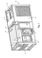
Figure 1 shows a front perspective view of an engine generator with improved efficiency and quiet operation according to a first embodiment of the present invention, -
Figure 2 shows a perspective top view of the engine generator ofFigure 1 , -
Figure 3 shows a front perspective view of the engine generator ofFigure 1 deprived of the front of the casing, -
Figure 4 shows a perspective top view of the engine generator ofFigure 1 , deprived of the top part of the housing, -
Figure 5 shows a left side perspective view of the engine generator ofFigure 1 , deprived of the left side part of the casing, -
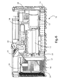
Figure 6 shows a rear perspective view in section of the engine generator ofFigure 1 , -
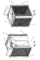
Figure 7A shows a first front perspective view of the electro radiator of the engine generator ofFigure 1 , -
Figure 7B shows a second front perspective view of the electro radiator of the engine generator inFigure 1 , -
Figure 8 shows a rear perspective view of the engine generator ofFigure 1 , -
Figure 9 shows a perspective view of the engine and of the alternator of the engine generator inFigure 1 , -
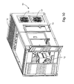
Figure 10 shows a front perspective view of an engine generator with improved efficiency and quiet operation according to a second embodiment of the present invention, -
Figure 11 is a right side perspective view of the engine generator ofFigure 10 . - Referring to the figures, an engine generator according to the present invention is generally indicated by
reference numeral 10 and is constituted by an internal combustion engine 11 (alternatively fueled by fossil fuel (diesel, gas) or from fuels from biomass (vegetable oils, biogas)) and of analternator 12, which converts the reciprocating motion of the engine 11 (mechanical energy) into electrical energy. - The
engine generator 10 also comprises acasing 13 which can be, depending on the needs, of various sizes and has as a characteristic a good degree of soundproofing, obtained with the use of sound-absorbing and sound-insulating panels (the thickness of which depends on the degree quiet operation required). - A fundamental characteristic of the engine generator of the present invention is not to provide for an ordinary radiator with constant speed for the cooling of the engine, but rather an
electro radiator 14 withfan 15 with variable speed. - This
electro radiator 14, depending on the electrical load, the temperature of the engine and the ambient temperature, through a system of sensors and solenoid valves, operated by a control and managepanel 25 within which are also present the connections for the attack of the various cables needed for the distribution of electricity, adjusts the speed of thefan 15, to cool the walls of theradiant mass 16 within which the cooling liquid from theengine 11 is passing and expels the excess heat upwards, in this way also contributing to maintain low noise emissions. - With reference to
Figures 7A and 7B , theradiant mass 16 of theelectro radiator 14 has considerable dimensions, its total area being greater than that of a traditional radiator. - The
electro radiator 14 is positioned in acompartment 17 totally compartmentalized and isolated from thecompartment 18 of theengine 11 and of thealternator 12 by a separatingdiaphragm 19, the only communication between the two compartments being due to thedelivery pipes 20 and thereturn pipes 21 of the cooling liquid going from theengine 11 to theelectro radiator 14 and vice versa. - Thanks to the
electro radiator 14 withfan 15 with variable speed, theengine generator 10 according to the present invention is able to dispose within thecompartment 17 about 70% of the heat produced by theinternal combustion engine 11, while the remaining 30% is disposed within thecompartment 18 of theengine 11 and of the alternator 12 (10% throughexhaust gas discharges electro fans 23 regulated by special sensors). - This distribution of the air flow and the variability of the speed of the
fan 15 as a function of heat to be removed is the key to the benefits of the engine generator according to the present invention, that are: - increasing the life of the engine generator;
- reduction of maintenance;
- adaptability to different climatic and environmental conditions;
- less noise;
- reduction of fuel consumption;
- lower emissions of exhaust gases to the benefit of the environment.
- In fact, the need to dispose of only 30% of the heat inside the
compartment 18 of theengine 11 and of thealternator 12 allows the casing to have a smaller number ofopenings 24 and then an airflow significantly reduced compared to a traditional engine generator , thus decreasing the input of aggressive elements such as dust, sand and salt and output of excessive noise. - The airflow used to dispose of the remaining 70% of heat does not cause major problems for engine generator according to the present invention, since the area of
electro radiator 14 is easily accessible, with the ability to automatically raise thefan 15, and then it is possible to clean it of any dirt and debris due to dust, sand and salt. - As far as the noise issue in relation to the area of the
electro radiator 14 is concerned, it is emphasized the fact that emissions are directed upwards and that thefan 15 is not always running at full speed. - Thanks to the limited penetration of dust, sand and salt in the
compartment 18 of theengine 11 and of thealternator 12, the engine generator according to the present invention undergoes a greater durability, regardless of the place of use (areas with temperate climate rather than hot, humid tropical climate, installations in normally urbanized areas rather than the desert or offshore platforms), and consequently also requires less maintenance. - In addition, thanks to the fact that it has low noise, it is possible to use the engine generator according to the present invention even in highly urbanized areas with high human activity, without creating excessive noise and respecting the laws in force in terms of noise emissions.
- In the last analysis, but no less important, not having a fan directly connected to the engine allows a substantial recovery of power and a considerable saving of fuel and a consequent reduction of emission of exhaust gases into the atmosphere.
- The
fan 15 of theelectro radiator 14, in fact, is in operation only when necessary and its extraction speed is a function of heat to be disposed and, above all, it has a consumption at maximum power of approximately 10% compared to a fan of a traditional radiator. - Furthermore, with reference to
Figures 10 and11 , relating to a second embodiment of the present invention, for the purpose of management of the airflow and the limitation of noise emissions, it is possible to provide for not asingle fan 15 disposed at the top, but four smaller fans 15', arranged on the sides of thecasing 13, drawing air into the interior ofcompartment 17 where it is positioned theelectro radiator 14. In this case, the accessibility for maintenance is guaranteed not from the top but from adoor 26 located on the short side of thecasing 13. - Referring back to the control and manage
panel 25, it also enables remote control and remote management through a dedicated control system and GPS and GPRS type antennas, which also enable the geolocation and monitoring of the engine generator. - In addition, for the purposes of limitation of noise emissions, all components of the
engine generator 10 may be treated with deadener varnishes, as well as it is possible to use special pots for residential use, which are very quiet. - Finally, where the components permits (engine - alternator), the engine generator according to the present invention is switchable from 50Hz to 60Hz and vice versa.
- The present invention has been described for illustrative but not limitative purposes, according to its preferred embodiments, but it is to be understood that variations and/or modifications can be apport by the skilled in the art without departing from the relevant scope of protection, as defined by the appended claims.
Claims (8)
- Engine generator (10) comprising an engine (11) and an alternator (12), housed inside a casing (13), as well as a cooling system based on a cooling fluid in turn cooled in a radiator (14) in which the radiating surface (16) is invested by an airflow conveyed by one or more fans (15, 15'), characterised in that the flow of the cooling fluid is constant and the airflow is variable.
- Engine generator (10) according to claim 1, characterised in that said radiator is an electro radiator (14) having one or more fans (15, 15') with variable speed, controlled by a system of sensors and solenoid valves, managed by a control and manage unit (25).
- Engine generator (10) according to claim 2, characterised in that said electro radiator (14) is positioned in a compartment (17) totally compartmentalised and isolated by a separate compartment (18) of the engine (11) and of the alternator (12) by means of a separating diaphragm (19), the only communication between the two compartments being due to the delivery pipes (20) and the return pipes (21) of said cooling fluid.
- Engine generator (10) according to claim 3, characterised in that, in correspondence of said compartment (18) of the engine (11) and of the alternator (12), said casing (13) has a limited numbers of openings (24).
- Engine generator (10) according to any of claims 2-4, characterised in that said one or more fans (15) are arranged upward with respect to said electro radiator (14) and direct air upwards.
- Engine generator (10) according to claim 5, characterised in that said one or more fans (15, 15') can be removed for maintenance access to said electro radiator (14).
- Engine generator (10) according to any of claims 2-4, characterised in that said one or more fans (15) are arranged laterally with respect to said electro radiator (14).
- Engine generator (10) according to any of claims 2-7, characterised in that said control and manage unit (25) comprises a system of GPS and GPRS type antennas, as well as geolocation devices.
Applications Claiming Priority (1)
| Application Number | Priority Date | Filing Date | Title |
|---|---|---|---|
| IT000011A ITRM20130011A1 (en) | 2013-01-09 | 2013-01-09 | ELECTROGEN GROUP WITH IMPROVED EFFICIENCY AND SILENCE. |
Publications (3)
| Publication Number | Publication Date |
|---|---|
| EP2754872A2 true EP2754872A2 (en) | 2014-07-16 |
| EP2754872A3 EP2754872A3 (en) | 2015-07-01 |
| EP2754872B1 EP2754872B1 (en) | 2017-08-02 |
Family
ID=47953594
Family Applications (1)
| Application Number | Title | Priority Date | Filing Date |
|---|---|---|---|
| EP13425121.4A Active EP2754872B1 (en) | 2013-01-09 | 2013-09-16 | Engine-generator with improved efficiency and low noise |
Country Status (3)
| Country | Link |
|---|---|
| EP (1) | EP2754872B1 (en) |
| ES (1) | ES2649416T3 (en) |
| IT (1) | ITRM20130011A1 (en) |
Cited By (4)
| Publication number | Priority date | Publication date | Assignee | Title |
|---|---|---|---|---|
| DE102015016725A1 (en) * | 2015-12-22 | 2017-06-22 | Man Diesel & Turbo Se | Control system and method for cooling a power plant |
| CN108999696A (en) * | 2018-08-24 | 2018-12-14 | 江西清华泰豪三波电机有限公司 | Power station radiator structure and silent power station |
| CN113696811A (en) * | 2021-07-22 | 2021-11-26 | 上海机电工程研究所 | Power supply vehicle for supplying power externally and working method |
| CN119611042A (en) * | 2024-12-09 | 2025-03-14 | 陕西北方动力有限责任公司 | A strong heat dissipation type vehicle-mounted intelligent power unit |
Family Cites Families (9)
| Publication number | Priority date | Publication date | Assignee | Title |
|---|---|---|---|---|
| JPS63186910A (en) * | 1987-01-29 | 1988-08-02 | Kubota Ltd | Engine generator cooling system |
| JPH02218813A (en) * | 1989-02-17 | 1990-08-31 | Rusoo Kk | Generator set |
| BE1013435A3 (en) * | 2000-05-12 | 2002-01-15 | Atlas Copco Airpower Nv | Power generator. |
| US6895903B2 (en) * | 2001-08-08 | 2005-05-24 | General Electric Company | Air provision systems for portable power modules |
| JP2004116308A (en) * | 2002-09-24 | 2004-04-15 | Nippon Oil Corp | Power generator |
| JP2006009762A (en) * | 2004-06-29 | 2006-01-12 | Denyo Co Ltd | Engine cooling system |
| JP2006322428A (en) * | 2005-05-20 | 2006-11-30 | Nishishiba Electric Co Ltd | Engine drive working device |
| US20110089911A1 (en) * | 2009-10-05 | 2011-04-21 | Jean-Marie Loisel | Integrated generator field flash |
| CN202348406U (en) * | 2011-11-17 | 2012-07-25 | 倍沃得热力技术(武汉)有限公司 | Novel upper-exhaust generating set |
-
2013
- 2013-01-09 IT IT000011A patent/ITRM20130011A1/en unknown
- 2013-09-16 EP EP13425121.4A patent/EP2754872B1/en active Active
- 2013-09-16 ES ES13425121.4T patent/ES2649416T3/en active Active
Non-Patent Citations (1)
| Title |
|---|
| None |
Cited By (5)
| Publication number | Priority date | Publication date | Assignee | Title |
|---|---|---|---|---|
| DE102015016725A1 (en) * | 2015-12-22 | 2017-06-22 | Man Diesel & Turbo Se | Control system and method for cooling a power plant |
| WO2017108212A1 (en) * | 2015-12-22 | 2017-06-29 | Man Diesel & Turbo Se | Control system and method for cooling a power plant |
| CN108999696A (en) * | 2018-08-24 | 2018-12-14 | 江西清华泰豪三波电机有限公司 | Power station radiator structure and silent power station |
| CN113696811A (en) * | 2021-07-22 | 2021-11-26 | 上海机电工程研究所 | Power supply vehicle for supplying power externally and working method |
| CN119611042A (en) * | 2024-12-09 | 2025-03-14 | 陕西北方动力有限责任公司 | A strong heat dissipation type vehicle-mounted intelligent power unit |
Also Published As
| Publication number | Publication date |
|---|---|
| EP2754872A3 (en) | 2015-07-01 |
| ITRM20130011A1 (en) | 2014-07-10 |
| ES2649416T3 (en) | 2018-01-11 |
| EP2754872B1 (en) | 2017-08-02 |
Similar Documents
| Publication | Publication Date | Title |
|---|---|---|
| US8677948B2 (en) | Variable speed high efficiency cooling system | |
| US10280870B2 (en) | Combined heat and power system | |
| US20080161974A1 (en) | Environmental control and power system | |
| US20090228149A1 (en) | Environmental control and power system | |
| EP2754872B1 (en) | Engine-generator with improved efficiency and low noise | |
| US7066114B1 (en) | Reverse fan operation for vehicle cooling system | |
| CN106014635A (en) | Container type diesel generator set suitable for high-environment-temperature work | |
| RU2008136778A (en) | HEAT INSTALLATION | |
| CN108104944A (en) | A kind of container-type generating set | |
| US8552574B2 (en) | Cogeneration apparatus | |
| CN203515796U (en) | Container-type gas turbine generator set | |
| CN119428140A (en) | Box structure and hybrid power integrated system including the same | |
| CN208534621U (en) | Box type gas generating set | |
| DE10151121B4 (en) | Combined heat and power | |
| FR2810076A1 (en) | Modular device for generating energy, e.g. for heating and air-conditioning of automotive vehicles | |
| CN206636647U (en) | A generator set integrated with dummy load by using water tank fan for heat dissipation | |
| Shams et al. | Applying the CHP method on small-scale on-site power generation | |
| CN106050430A (en) | Inlet air cooling control system for gas turbine | |
| CN204344223U (en) | The diesel engine cooling system of indoor layout | |
| CN110953065A (en) | Generating set with unit volume and ultrahigh power | |
| KR101202500B1 (en) | A agricultural work vehicle | |
| RU2755374C1 (en) | Electric generator unit | |
| CN203022912U (en) | Automobile waste heat power generation device | |
| RU48366U1 (en) | AUTONOMOUS HEAT POWER PLANT | |
| RU2359143C1 (en) | Power installation |
Legal Events
| Date | Code | Title | Description |
|---|---|---|---|
| PUAI | Public reference made under article 153(3) epc to a published international application that has entered the european phase |
Free format text: ORIGINAL CODE: 0009012 |
|
| 17P | Request for examination filed |
Effective date: 20130916 |
|
| AK | Designated contracting states |
Kind code of ref document: A2 Designated state(s): AL AT BE BG CH CY CZ DE DK EE ES FI FR GB GR HR HU IE IS IT LI LT LU LV MC MK MT NL NO PL PT RO RS SE SI SK SM TR |
|
| AX | Request for extension of the european patent |
Extension state: BA ME |
|
| PUAL | Search report despatched |
Free format text: ORIGINAL CODE: 0009013 |
|
| AK | Designated contracting states |
Kind code of ref document: A3 Designated state(s): AL AT BE BG CH CY CZ DE DK EE ES FI FR GB GR HR HU IE IS IT LI LT LU LV MC MK MT NL NO PL PT RO RS SE SI SK SM TR |
|
| AX | Request for extension of the european patent |
Extension state: BA ME |
|
| RIC1 | Information provided on ipc code assigned before grant |
Ipc: F01P 7/02 20060101AFI20150527BHEP Ipc: F02B 63/04 20060101ALI20150527BHEP |
|
| R17P | Request for examination filed (corrected) |
Effective date: 20151130 |
|
| RBV | Designated contracting states (corrected) |
Designated state(s): AL AT BE BG CH CY CZ DE DK EE ES FI FR GB GR HR HU IE IS IT LI LT LU LV MC MK MT NL NO PL PT RO RS SE SI SK SM TR |
|
| 17Q | First examination report despatched |
Effective date: 20160405 |
|
| GRAP | Despatch of communication of intention to grant a patent |
Free format text: ORIGINAL CODE: EPIDOSNIGR1 |
|
| STAA | Information on the status of an ep patent application or granted ep patent |
Free format text: STATUS: GRANT OF PATENT IS INTENDED |
|
| INTG | Intention to grant announced |
Effective date: 20170426 |
|
| GRAS | Grant fee paid |
Free format text: ORIGINAL CODE: EPIDOSNIGR3 |
|
| GRAA | (expected) grant |
Free format text: ORIGINAL CODE: 0009210 |
|
| STAA | Information on the status of an ep patent application or granted ep patent |
Free format text: STATUS: THE PATENT HAS BEEN GRANTED |
|
| AK | Designated contracting states |
Kind code of ref document: B1 Designated state(s): AL AT BE BG CH CY CZ DE DK EE ES FI FR GB GR HR HU IE IS IT LI LT LU LV MC MK MT NL NO PL PT RO RS SE SI SK SM TR |
|
| REG | Reference to a national code |
Ref country code: CH Ref legal event code: EP Ref country code: AT Ref legal event code: REF Ref document number: 914749 Country of ref document: AT Kind code of ref document: T Effective date: 20170815 |
|
| REG | Reference to a national code |
Ref country code: IE Ref legal event code: FG4D |
|
| REG | Reference to a national code |
Ref country code: DE Ref legal event code: R096 Ref document number: 602013024309 Country of ref document: DE |
|
| REG | Reference to a national code |
Ref country code: FR Ref legal event code: PLFP Year of fee payment: 5 |
|
| REG | Reference to a national code |
Ref country code: NL Ref legal event code: FP |
|
| REG | Reference to a national code |
Ref country code: AT Ref legal event code: MK05 Ref document number: 914749 Country of ref document: AT Kind code of ref document: T Effective date: 20170802 |
|
| REG | Reference to a national code |
Ref country code: LT Ref legal event code: MG4D |
|
| REG | Reference to a national code |
Ref country code: ES Ref legal event code: FG2A Ref document number: 2649416 Country of ref document: ES Kind code of ref document: T3 Effective date: 20180111 |
|
| PG25 | Lapsed in a contracting state [announced via postgrant information from national office to epo] |
Ref country code: LT Free format text: LAPSE BECAUSE OF FAILURE TO SUBMIT A TRANSLATION OF THE DESCRIPTION OR TO PAY THE FEE WITHIN THE PRESCRIBED TIME-LIMIT Effective date: 20170802 Ref country code: HR Free format text: LAPSE BECAUSE OF FAILURE TO SUBMIT A TRANSLATION OF THE DESCRIPTION OR TO PAY THE FEE WITHIN THE PRESCRIBED TIME-LIMIT Effective date: 20170802 Ref country code: NO Free format text: LAPSE BECAUSE OF FAILURE TO SUBMIT A TRANSLATION OF THE DESCRIPTION OR TO PAY THE FEE WITHIN THE PRESCRIBED TIME-LIMIT Effective date: 20171102 Ref country code: AT Free format text: LAPSE BECAUSE OF FAILURE TO SUBMIT A TRANSLATION OF THE DESCRIPTION OR TO PAY THE FEE WITHIN THE PRESCRIBED TIME-LIMIT Effective date: 20170802 Ref country code: SE Free format text: LAPSE BECAUSE OF FAILURE TO SUBMIT A TRANSLATION OF THE DESCRIPTION OR TO PAY THE FEE WITHIN THE PRESCRIBED TIME-LIMIT Effective date: 20170802 Ref country code: FI Free format text: LAPSE BECAUSE OF FAILURE TO SUBMIT A TRANSLATION OF THE DESCRIPTION OR TO PAY THE FEE WITHIN THE PRESCRIBED TIME-LIMIT Effective date: 20170802 |
|
| PG25 | Lapsed in a contracting state [announced via postgrant information from national office to epo] |
Ref country code: IS Free format text: LAPSE BECAUSE OF FAILURE TO SUBMIT A TRANSLATION OF THE DESCRIPTION OR TO PAY THE FEE WITHIN THE PRESCRIBED TIME-LIMIT Effective date: 20171202 Ref country code: BG Free format text: LAPSE BECAUSE OF FAILURE TO SUBMIT A TRANSLATION OF THE DESCRIPTION OR TO PAY THE FEE WITHIN THE PRESCRIBED TIME-LIMIT Effective date: 20171102 Ref country code: GR Free format text: LAPSE BECAUSE OF FAILURE TO SUBMIT A TRANSLATION OF THE DESCRIPTION OR TO PAY THE FEE WITHIN THE PRESCRIBED TIME-LIMIT Effective date: 20171103 Ref country code: RS Free format text: LAPSE BECAUSE OF FAILURE TO SUBMIT A TRANSLATION OF THE DESCRIPTION OR TO PAY THE FEE WITHIN THE PRESCRIBED TIME-LIMIT Effective date: 20170802 Ref country code: LV Free format text: LAPSE BECAUSE OF FAILURE TO SUBMIT A TRANSLATION OF THE DESCRIPTION OR TO PAY THE FEE WITHIN THE PRESCRIBED TIME-LIMIT Effective date: 20170802 Ref country code: PL Free format text: LAPSE BECAUSE OF FAILURE TO SUBMIT A TRANSLATION OF THE DESCRIPTION OR TO PAY THE FEE WITHIN THE PRESCRIBED TIME-LIMIT Effective date: 20170802 |
|
| PG25 | Lapsed in a contracting state [announced via postgrant information from national office to epo] |
Ref country code: RO Free format text: LAPSE BECAUSE OF FAILURE TO SUBMIT A TRANSLATION OF THE DESCRIPTION OR TO PAY THE FEE WITHIN THE PRESCRIBED TIME-LIMIT Effective date: 20170802 Ref country code: DK Free format text: LAPSE BECAUSE OF FAILURE TO SUBMIT A TRANSLATION OF THE DESCRIPTION OR TO PAY THE FEE WITHIN THE PRESCRIBED TIME-LIMIT Effective date: 20170802 Ref country code: CZ Free format text: LAPSE BECAUSE OF FAILURE TO SUBMIT A TRANSLATION OF THE DESCRIPTION OR TO PAY THE FEE WITHIN THE PRESCRIBED TIME-LIMIT Effective date: 20170802 |
|
| REG | Reference to a national code |
Ref country code: CH Ref legal event code: PL |
|
| REG | Reference to a national code |
Ref country code: DE Ref legal event code: R097 Ref document number: 602013024309 Country of ref document: DE |
|
| PG25 | Lapsed in a contracting state [announced via postgrant information from national office to epo] |
Ref country code: SK Free format text: LAPSE BECAUSE OF FAILURE TO SUBMIT A TRANSLATION OF THE DESCRIPTION OR TO PAY THE FEE WITHIN THE PRESCRIBED TIME-LIMIT Effective date: 20170802 Ref country code: EE Free format text: LAPSE BECAUSE OF FAILURE TO SUBMIT A TRANSLATION OF THE DESCRIPTION OR TO PAY THE FEE WITHIN THE PRESCRIBED TIME-LIMIT Effective date: 20170802 Ref country code: SM Free format text: LAPSE BECAUSE OF FAILURE TO SUBMIT A TRANSLATION OF THE DESCRIPTION OR TO PAY THE FEE WITHIN THE PRESCRIBED TIME-LIMIT Effective date: 20170802 Ref country code: MC Free format text: LAPSE BECAUSE OF FAILURE TO SUBMIT A TRANSLATION OF THE DESCRIPTION OR TO PAY THE FEE WITHIN THE PRESCRIBED TIME-LIMIT Effective date: 20170802 |
|
| PLBE | No opposition filed within time limit |
Free format text: ORIGINAL CODE: 0009261 |
|
| STAA | Information on the status of an ep patent application or granted ep patent |
Free format text: STATUS: NO OPPOSITION FILED WITHIN TIME LIMIT |
|
| PG25 | Lapsed in a contracting state [announced via postgrant information from national office to epo] |
Ref country code: LU Free format text: LAPSE BECAUSE OF NON-PAYMENT OF DUE FEES Effective date: 20170916 |
|
| 26N | No opposition filed |
Effective date: 20180503 |
|
| PG25 | Lapsed in a contracting state [announced via postgrant information from national office to epo] |
Ref country code: CH Free format text: LAPSE BECAUSE OF NON-PAYMENT OF DUE FEES Effective date: 20170930 Ref country code: LI Free format text: LAPSE BECAUSE OF NON-PAYMENT OF DUE FEES Effective date: 20170930 |
|
| PG25 | Lapsed in a contracting state [announced via postgrant information from national office to epo] |
Ref country code: SI Free format text: LAPSE BECAUSE OF FAILURE TO SUBMIT A TRANSLATION OF THE DESCRIPTION OR TO PAY THE FEE WITHIN THE PRESCRIBED TIME-LIMIT Effective date: 20170802 |
|
| REG | Reference to a national code |
Ref country code: FR Ref legal event code: PLFP Year of fee payment: 6 |
|
| PG25 | Lapsed in a contracting state [announced via postgrant information from national office to epo] |
Ref country code: MT Free format text: LAPSE BECAUSE OF NON-PAYMENT OF DUE FEES Effective date: 20170916 |
|
| PG25 | Lapsed in a contracting state [announced via postgrant information from national office to epo] |
Ref country code: HU Free format text: LAPSE BECAUSE OF FAILURE TO SUBMIT A TRANSLATION OF THE DESCRIPTION OR TO PAY THE FEE WITHIN THE PRESCRIBED TIME-LIMIT; INVALID AB INITIO Effective date: 20130916 |
|
| PG25 | Lapsed in a contracting state [announced via postgrant information from national office to epo] |
Ref country code: CY Free format text: LAPSE BECAUSE OF NON-PAYMENT OF DUE FEES Effective date: 20170802 |
|
| PG25 | Lapsed in a contracting state [announced via postgrant information from national office to epo] |
Ref country code: MK Free format text: LAPSE BECAUSE OF FAILURE TO SUBMIT A TRANSLATION OF THE DESCRIPTION OR TO PAY THE FEE WITHIN THE PRESCRIBED TIME-LIMIT Effective date: 20170802 |
|
| PG25 | Lapsed in a contracting state [announced via postgrant information from national office to epo] |
Ref country code: TR Free format text: LAPSE BECAUSE OF FAILURE TO SUBMIT A TRANSLATION OF THE DESCRIPTION OR TO PAY THE FEE WITHIN THE PRESCRIBED TIME-LIMIT Effective date: 20170802 |
|
| PG25 | Lapsed in a contracting state [announced via postgrant information from national office to epo] |
Ref country code: PT Free format text: LAPSE BECAUSE OF FAILURE TO SUBMIT A TRANSLATION OF THE DESCRIPTION OR TO PAY THE FEE WITHIN THE PRESCRIBED TIME-LIMIT Effective date: 20170802 |
|
| PG25 | Lapsed in a contracting state [announced via postgrant information from national office to epo] |
Ref country code: AL Free format text: LAPSE BECAUSE OF FAILURE TO SUBMIT A TRANSLATION OF THE DESCRIPTION OR TO PAY THE FEE WITHIN THE PRESCRIBED TIME-LIMIT Effective date: 20170802 |
|
| PGFP | Annual fee paid to national office [announced via postgrant information from national office to epo] |
Ref country code: DE Payment date: 20250926 Year of fee payment: 13 |
|
| PGFP | Annual fee paid to national office [announced via postgrant information from national office to epo] |
Ref country code: NL Payment date: 20250925 Year of fee payment: 13 Ref country code: IT Payment date: 20250923 Year of fee payment: 13 |
|
| PGFP | Annual fee paid to national office [announced via postgrant information from national office to epo] |
Ref country code: BE Payment date: 20250925 Year of fee payment: 13 Ref country code: GB Payment date: 20250923 Year of fee payment: 13 |
|
| PGFP | Annual fee paid to national office [announced via postgrant information from national office to epo] |
Ref country code: FR Payment date: 20250925 Year of fee payment: 13 |
|
| PGFP | Annual fee paid to national office [announced via postgrant information from national office to epo] |
Ref country code: IE Payment date: 20250917 Year of fee payment: 13 |
|
| PGFP | Annual fee paid to national office [announced via postgrant information from national office to epo] |
Ref country code: ES Payment date: 20251015 Year of fee payment: 13 |