EP2754151B1 - Dispositif, procédé et système électroacoustique de prolongement d'un temps de réverbération - Google Patents
Dispositif, procédé et système électroacoustique de prolongement d'un temps de réverbération Download PDFInfo
- Publication number
- EP2754151B1 EP2754151B1 EP12756411.0A EP12756411A EP2754151B1 EP 2754151 B1 EP2754151 B1 EP 2754151B1 EP 12756411 A EP12756411 A EP 12756411A EP 2754151 B1 EP2754151 B1 EP 2754151B1
- Authority
- EP
- European Patent Office
- Prior art keywords
- virtual
- wave field
- field synthesis
- loudspeaker
- synthesis information
- Prior art date
- Legal status (The legal status is an assumption and is not a legal conclusion. Google has not performed a legal analysis and makes no representation as to the accuracy of the status listed.)
- Active
Links
- 238000000034 method Methods 0.000 title claims description 38
- 230000015572 biosynthetic process Effects 0.000 claims description 65
- 238000003786 synthesis reaction Methods 0.000 claims description 65
- 238000004590 computer program Methods 0.000 claims description 12
- 238000001914 filtration Methods 0.000 claims description 7
- 230000003111 delayed effect Effects 0.000 claims description 4
- 238000004364 calculation method Methods 0.000 description 21
- 230000005236 sound signal Effects 0.000 description 21
- 239000011159 matrix material Substances 0.000 description 8
- 238000010521 absorption reaction Methods 0.000 description 6
- 238000004422 calculation algorithm Methods 0.000 description 6
- 238000012545 processing Methods 0.000 description 6
- 230000005540 biological transmission Effects 0.000 description 4
- 238000010276 construction Methods 0.000 description 4
- 238000005516 engineering process Methods 0.000 description 3
- 238000009877 rendering Methods 0.000 description 3
- 238000010586 diagram Methods 0.000 description 2
- 230000003993 interaction Effects 0.000 description 2
- 239000000463 material Substances 0.000 description 2
- 230000001172 regenerating effect Effects 0.000 description 2
- 241000122235 Junco hyemalis Species 0.000 description 1
- 230000006978 adaptation Effects 0.000 description 1
- 230000003321 amplification Effects 0.000 description 1
- 238000013459 approach Methods 0.000 description 1
- 238000004891 communication Methods 0.000 description 1
- 230000007423 decrease Effects 0.000 description 1
- 230000001934 delay Effects 0.000 description 1
- 238000001514 detection method Methods 0.000 description 1
- 238000006073 displacement reaction Methods 0.000 description 1
- 230000000694 effects Effects 0.000 description 1
- 238000012986 modification Methods 0.000 description 1
- 230000004048 modification Effects 0.000 description 1
- 238000003199 nucleic acid amplification method Methods 0.000 description 1
- 230000008929 regeneration Effects 0.000 description 1
- 238000011069 regeneration method Methods 0.000 description 1
- 230000003362 replicative effect Effects 0.000 description 1
- 238000004088 simulation Methods 0.000 description 1
- 230000001629 suppression Effects 0.000 description 1
- 230000002123 temporal effect Effects 0.000 description 1
- 238000012360 testing method Methods 0.000 description 1
- 238000012800 visualization Methods 0.000 description 1
Images


Classifications
-
- G—PHYSICS
- G10—MUSICAL INSTRUMENTS; ACOUSTICS
- G10K—SOUND-PRODUCING DEVICES; METHODS OR DEVICES FOR PROTECTING AGAINST, OR FOR DAMPING, NOISE OR OTHER ACOUSTIC WAVES IN GENERAL; ACOUSTICS NOT OTHERWISE PROVIDED FOR
- G10K15/00—Acoustics not otherwise provided for
- G10K15/08—Arrangements for producing a reverberation or echo sound
- G10K15/12—Arrangements for producing a reverberation or echo sound using electronic time-delay networks
-
- H—ELECTRICITY
- H04—ELECTRIC COMMUNICATION TECHNIQUE
- H04S—STEREOPHONIC SYSTEMS
- H04S7/00—Indicating arrangements; Control arrangements, e.g. balance control
- H04S7/30—Control circuits for electronic adaptation of the sound field
-
- H—ELECTRICITY
- H04—ELECTRIC COMMUNICATION TECHNIQUE
- H04S—STEREOPHONIC SYSTEMS
- H04S2420/00—Techniques used stereophonic systems covered by H04S but not provided for in its groups
- H04S2420/13—Application of wave-field synthesis in stereophonic audio systems
Definitions
- the present invention relates to a device, a method and an electroacoustic system for reverberation time extension.
- a room is not optimal for different applications from an acoustic point of view. So a musical performance usually requires some reverb to sound good. On the other hand, speakers are sometimes incomprehensible when the room is too reverberant. An adjustment of the reverberation time with the help of a public address system is therefore useful.
- electroacoustic systems for reverberation time extension can be used. Such systems can either be e.g. be retrofitted into an existing concert hall. Likewise, however, it may be useful to begin with the construction and construction of corresponding buildings and halls, e.g. in trade fair construction, to provide an electroacoustic system for reverberation time extension and to include it in the planning of the building. Also in the context of audio playback for entertainment purposes, a reverberation time extension may be desirable.
- Wave Field Synthesis was researched at the TU Delft and first presented in the late 1980s ( Berkhout, AJ; de Vries, D .; Vogel, P .: Acoustic control by wave-field synthesis. JASA 93, 1993 ).
- the advantage of this technique is in particular that a natural spatial sound impression over a large area of the playback room is possible.
- the direction and distance of sound sources are reproduced very accurately.
- virtual sound sources can even be positioned between the real speaker array and the listener.
- wave field synthesis is based on the principle of Huygens, according to which wavefronts can be formed and built up by superimposing elementary waves. After mathematically exact theoretical description, infinitely many sources in infinitely small distance would have to be used for the generation of the elementary waves. Practically, however, many speakers are finally used at a finite distance from each other. Each of these speakers is driven according to the WFS principle with an audio signal from a virtual source having a particular delay and a certain level. Levels and delays are usually different for all speakers.
- a wave field synthesis system operates on the Huygens principle and reconstructs a given waveform, for example, of a virtual source located at a certain distance from a listener by a plurality of single waves.
- the wave-field synthesis algorithm thus obtains information about the actual position of a single loudspeaker from the loudspeaker array and then calculates a component signal for this single loudspeaker that this loudspeaker ultimately has to emit, so that the listener can superimpose the loudspeaker signal from one loudspeaker to the loudspeaker signals from the other active loudspeaker Speaker performs a reconstruction in that the listener has the impression that he is not "sonicated" by many individual speakers, but only from a single speaker at the position of the virtual source.
- each virtual source for each loudspeaker that is, the component signal of the first virtual source for the first loudspeaker, the second virtual source for the first loudspeaker, etc.
- the contribution from each virtual source for each loudspeaker is calculated to then add up the component signals finally get the actual speaker signal.
- superimposing the loudspeaker signals of all the active loudspeakers on the listener would mean that the listener does not feel that he is being sonicated by a large array of loudspeakers, but that the sound he hears is merely from three sound sources positioned at specific positions, which are equal to the virtual sources.
- the calculation of the component signals usually takes place in practice by applying a delay and a scaling factor to the audio source assigned to a virtual source, depending on the position of the virtual source and the position of the loudspeaker, at a specific point in time in order to obtain a delayed and / or scaled audio signal to obtain a virtual source that directly represents the loudspeaker signal when there is only one virtual source, or that after addition of other component signals for the considered loudspeaker from other virtual sources then contributes to the loudspeaker signal for the considered loudspeaker.
- Typical wave field synthesis algorithms operate regardless of how many speakers are present in the speaker array.
- the underlying theory of Wave Field Synthesis is that any sound field can be accurately reconstructed by an infinite number of individual speakers, with the individual individual speakers arranged infinitely close to each other. In practice, however, neither the infinite number nor the infinitely close arrangement will be realized. Instead, there are a limited number of speakers, which are also arranged at certain predetermined distances from each other. Thus, in real systems, only an approximation to the actual waveform that would occur if the virtual source were actually present, would be a real source.
- Wave field synthesis devices are also capable of replicating several different types of sources.
- a prominent source form is the point source, where the level decreases proportionally 1 / r, where r is the distance between a listener and the position of the virtual source.
- Another source form is a source that emits plane waves.
- the level remains constant regardless of the distance to the listener, since plane waves can be generated by point sources, which are arranged at an infinite distance.
- Wave Field Synthesis is referred to the problems of rendering stereophonic sound sources and integrating different signal and test configurations to give a comprehensive insight and overview of the sound recording and reproduction process.
- the object of the present invention is therefore to provide improved concepts for devices, methods and electroacoustic systems for reverberation time extension.
- the object of the present invention is achieved by a device according to claim 1, a method according to claim 12, a computer program according to claim 13, an electroacoustic system according to claim 14 and a method according to claim 15.
- the invention provides a device for reverberation time extension.
- the apparatus comprises a wave field synthesis information calculation module and a signal processor for generating a plurality of audio output signals for a plurality of loud speakers based on a plurality of audio input signals, and based on the wave field synthesis information, the audio signals being received from a plurality of microphones.
- the device comprises an operating unit for determining a virtual position of one or more virtual walls.
- the wave field synthesis information calculation module is configured to calculate the wave field synthesis information based on the virtual position of the one or more virtual walls.
- the virtual position can be set by the operating unit for at least one of the virtual walls.
- the acoustic amplification is also achieved by a regenerative effect, which consists in that the output via speakers generated audio output signals are picked up again by the microphones and thus enter into the generation of the audio output signals at a later date.
- an apparatus and method for generating an acoustic spatial magnification wherein distributed microphones detect relevant sound sources and the acoustic environment and reproduce this with respect to fixed or dynamic virtual source positions via a wave field synthesis system.
- the invention is based on the concept that the virtual sources are generated in an algorithm based on wave field synthesis.
- the invention describes a method in which by means of distributed microphones in the room to be sounded, the acoustics of the room is detected with the sources to be amplified and a AD converter Processing system is supplied.
- the processing system may consist of software in which the signal is first processed via filters, and then processed in a wave field synthesis algorithm to an object-based sound source, which in turn is processed via filters, to then be played over a wave field synthesis system. Due to the possibilities of wave field synthesis, the acquired room signals can now be positioned as desired and can be moved as "virtual walls" as desired. As a result, individual room geometries can be generated.
- the recorded space signals are typically represented as plane waves and thus correspond to the acoustic effect of a wall. Not only can this virtual wall be moved, it can also be changed in angle, directly affecting the reflection patterns of the sound sources.
- the wave field synthesis information calculation module is configured to calculate delay values and amplitude factor values as wave field synthesis information.
- the delay value indicates the delay by which one of the audio input signals is delayed at one of the speakers.
- the amplitude factor value indicates by what factor the amplitude of one of the audio input signals is modified to obtain a modified signal output at one of the speakers.
- the wave field synthesis information calculation module may be configured to calculate a delay value and an amplitude factor value for each speaker-virtual wall pair at a time, wherein a speaker-virtual wall pair, a pair of one of the speakers and one of the virtual walls is.
- the wave field synthesis information calculation module is configured to apply the delay value and the amplitude factor value to a speaker-virtual wall pair based on the distance from the speaker and the virtual wall of the speaker-virtual wall pair to calculate.
- the wave field synthesis information calculation module may be configured to set the delay value of a speaker virtual wall pair the larger the distance between the speaker and the virtual wall.
- the wave field synthesis information calculation module may be configured to set the amplitude factor value of a speaker-virtual wall pair the smaller the distance between the speaker and the virtual wall.
- the operating unit is designed so that at least one of the virtual walls is displaceable from a first virtual position to a second virtual position, so that the virtual wall can be displaced in any desired parallel position relative to its first position.
- the operating unit can be designed such that at least one of the virtual walls is displaceable from a first virtual position to a second virtual position, so that the virtual wall can be displaced in any rotationally opposite its first position.
- the operating unit is designed so that the virtual position can be set by the operating unit for all of the virtual walls.
- the operating unit can be designed such that each of the virtual walls can be displaced from a first virtual position to a second virtual position. so that each virtual wall is arbitrarily parallel and rotatable relative to its first position.
- the reverberation time extension apparatus may include a parametric filter for filtering resonant frequencies.
- an electroacoustic reverberation time extension system comprising a plurality of microphones, a reverberation time extension apparatus according to any one of the above-described embodiments, and a loudspeaker array of a plurality of loud speakers.
- the plurality of microphones are configured to generate a plurality of audio input signals fed to the reverberation time extension apparatus, and wherein the plurality of loudspeakers of the loudspeaker array are adapted to receive and feed the audio output signals from the reverberation time extension apparatus Play audio output signals.
- Fig. 1 shows a device for reverberation time extension according to one embodiment.
- the apparatus includes a wave field synthesis information calculation module 110. Further, the apparatus includes a signal processor 120 for generating a plurality of audio output signals y 1 , y 2 ,..., Y n for a plurality of loud speakers (not shown) based on a plurality of audio input signals s 1 , s 2 , ..., s n picked up by a plurality of microphones (not shown) and based on the wave field synthesis information. Furthermore, the device comprises an operating unit 130 for determining a virtual position of one or more virtual walls.
- the wave field synthesis information calculation module 110 is configured to calculate the wave field synthesis information WS inf based on the virtual position of the one or more virtual walls. In this case, its virtual position can be set by the operating unit for at least one of the virtual walls.
- the wave field synthesis information calculation module 110 and the signal processor 120 may be implemented in one module (a wave field synthesis module).
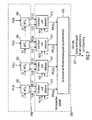
- Fig. 2 an embodiment of the interaction of the module for calculating wave field synthesis information and the signal processor set forth.
- the wave field synthesis information calculation module 210 and the signal processor 220 are shown by dashed lines.
- the wave field synthesis information calculation module 210 and the signal processor 220 have a highly parallel construction in that, starting from the audio signal supplied to the signal processor for each virtual wall (a virtual source) and from the position information for the corresponding virtual wall (virtual source), which has received the module for calculating wave field synthesis information 210 from an operation unit, first delay information (delay information) V i and amplitude factors (scaling factors) SF i are calculated by the position information and the position of the currently considered loudspeaker, z. B. the speaker with the ordinal number j, so LS j depend.
- a discrete value AW i (t A) for the Computed signal K ij calculated in a final received speaker signal is shown schematically.
- Fig. 2 also shows a kind of "flash photography" at time t A for the individual component signals. The individual component signals are then summed by a summer 320 in nodes to determine the discrete value for the current time t A of the loudspeaker signal for the speaker j, which can then be supplied to the speaker for the output.
- a value valid on the basis of a delay information and a scale factor (scaling factor) at a current time is first calculated for each virtual source, after which all the component signals for a loudspeaker due to the different virtual walls (virtual sources ) are summed up. For example, if only one virtual source were present, then the summer would be omitted, and that at the output of the summer in Fig. 2 applied signal would z. B. the signal output from the device 310 when the virtual source 1 is the only virtual source.
- Fig. 3 illustrates an electroacoustic WFS system for reverberation time extension according to an embodiment.
- Fig. 3 are installed in a room evenly four microphones 350 1m suspended from the ceiling.
- the microphone signals are processed in a WFS algorithm 360 to a virtual source, which is reproduced as a plane wave via a WFS sound system 370 in the same room.
- the WFS system includes a user interface for moving the 4 microphone sources. With this control unit, the 4 microphone signals are detected and pulled outwards. The result is an acoustic enlargement of the room.
- the wave field synthesis module 360 includes a wave field synthesis information calculation module according to the embodiment of FIG Fig. 1 and a signal processor according to the embodiment of FIG Fig. 1 ,
- the operating unit 375 is an operating unit according to the embodiment of FIG Fig. 1 ,
- unit 355 sets in Fig. 3 a filter which serves to filter resonance frequencies.
- a sound wave output at one of the speakers 370 is resumed by the microphones 350 and re-considered in the generation of the later audio signal output via the speakers.
- filter 355 can be used to suppress these resonances.
- filter 365 may be a conventional filter used, for example, to adapt the speakers.
- Fig. 4 illustrates another embodiment of an electroacoustic WFS system.
- the signals of the ceiling microphones are processed in a central processing unit and processed after filtering in a matrix to virtual sources, which is played back after level adjustment, control of the spatial proportion and speaker filtering as virtual sound sources via a WFS array and evenly distributed ceiling speakers.
- Microphones feed 411, 412 audio input signals into Microphone Preamplifier 416, 417.
- the microphone 411 is a microphone that is close to a sound source such as a lectern.
- the microphone 412 is a room microphone located in the room but farther from the sound source than the microphone 411. Typically, multiple room microphones and / or multiple microphones are used close to the sound source.
- Microphone preamplifiers 416, 417 amplify the audio input signals received from the microphones 411, 412 to obtain preamplified audio input signals.
- the microphone preamplifiers 416, 417 may be conventional microphone preamplifiers.
- the pre-amplified audio input signals are fed to an analog-to-digital converter 420, which converts the audio input signals, which are initially in analog form, into digital audio signals.
- the analog-to-digital converter 420 may be a conventional analog-to-digital converter.
- the analog-to-digital converter 420 feeds the digital audio signals into the absorption filter 425.
- Absorption filter 425 performs filtering to match the wall material.
- absorption filter 425 filters such that when highly reflective walls are to be replicated, the digital audio signals pass absorption filter 425 almost unfiltered.
- absorption filter 425 in one embodiment filters the digital audio signals to a great extent.
- Filter 430 is a filter for feedback compensation and sound adjustment. If a signal is reproduced by a loudspeaker, the sound waves of this signal are in turn detected by the microphone and this leads to a feedback. In one embodiment, filter 430 may be used to provide this feedback entirely or partially compensate. In addition, Filter 430 can be used for sound adjustment. In one embodiment, the feedback compensation and / or the sound adjustment may be performed in a conventional manner.
- the system includes in Fig. 4 a central operating unit 435 and a module for calculating wave field synthesis information 440.
- the central operating unit 435 of the operating unit in Fig. 1 correspond.
- the central operating unit in Fig. 4 can be equipped with a GUI (Graphical User Interface).
- the wave field synthesis information calculation module 440 may be adapted to the wave field synthesis information calculation module Fig. 1 correspond.
- the wave field synthesis information calculation module 440 passes the calculated wave field synthesis parameters to module 445.
- These wave field synthesis parameters may be e.g. to act on delay values and amplitude values, such as amplitude factor values.
- Module 445 builds a Delay Amplitude Matrix from the values passed by Module 440.
- the delay amplitude matrix may include a delay value and an amplitude factor value for a particular point in time for each speaker-virtual wall pair.
- Module 445 performs audio scaling based on the wave field synthesis parameters obtained from the wave field synthesis information calculation module 440. For example, if a delay value and an amplitude factor value were obtained for a loudspeaker-virtual wall pair, the signal originating from the virtual wall (eg, apparently reflected from the virtual wall) will be the received delay value is delayed, and the amplitude factor value obtained from module 440 is modified to the amplitude of the signal to be output by the amplitude factor value, for example by multiplying the amplitude factor value by the amplitude of the signal to be output.
- filter 450 filters the module 445 modified audio signals to achieve speaker matching.
- the audio signals are modified to adjust the overall volume. This can be done in the usual way.
- the ratio of volume proportion to original signal is adjusted. For example, in one embodiment, the ratio of audio signals generated from audio signals of room microphones were adjusted to audio signals that were generated from audio signals of microphones near the lectern, for example by adjusting the amplitudes of the respective signals.
- the modified digital audio signals are then fed to a digital-to-analog converter 465 which converts the modified digital audio signals to analog audio output signals.
- the analog audio output signals are then amplified by power amplifiers 471, 472 and output from loudspeakers 481, 482.
- the audio signals are output from either WFS speakers 481 or ceiling speakers 482. It is understood that in a real system a variety of WFS speakers and / or ceiling speakers can be used.
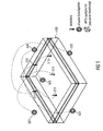
- Fig. 5 shows a medium conference room (5mx18x15m) equipped with 5 ceiling microphones 511, 512, 513, 514, 515, 40 ceiling loudspeakers and a circulating horizontal band of conventional loudspeakers in a reduced WFS arrangement 530.
- the signals of the ceiling microphones 511, 512, 513, 514, 515 are processed in a central processing unit and processed after filtering in a matrix to virtual sources, which after level adjustment, control of the spatial proportion and speaker filtering as virtual sound sources 521, 522, 523, 524, 525 via a WFS array and evenly distributed ceiling speakers is played again.
- the structure shows FIG. 4 ,
- the microphone signals are represented by the respectively opposite virtual sources in order to avoid feedback.
- the input branch of the matrix also contains a filter unit which takes into account different spatial materials in order to incorporate various absorption and reflection parameters into the space to be reverberated.
- the detected microphone signals are reproduced in freely positionable sources as described imaged and acted upon by the existing room characteristics again captured by the microphone, which leads to a regeneration of the room acoustics.
- Fig. 6 illustrates a basic concept of certain embodiments. Shown is a speaker array that, as in Fig. 6 12 speakers 611, 612, 613. In actual embodiments, the number of loudspeakers will often be significantly larger and include, for example, 60, 100, 200, 300 or more loudspeakers. Also shown are four virtual walls 621, 622, 623, 624.
- the speaker 611 and the virtual wall 621 will be considered in more detail. These form a speaker-virtual wall pair (611, 621). Also, any other combination of one of the speakers and one of the virtual walls forms a speaker-virtual wall pair. The distance between the speaker and the virtual wall is indicated by an arrow d. In Fig. 6 In addition, a plurality of microphones 631, 632, 633 is provided. For the sake of simplicity, it is assumed that a microphone 631 generates an audio signal to be reproduced through the speaker 611 by recording sound waves. In this case, the signal reproduced by the loudspeaker 611 should correspond to a reflection of the sound waves recorded by the microphone 631 on the virtual wall 621.
- the signal picked up by the microphone can only be reproduced with a time delay by the loudspeaker 611, which depends on the distance between the loudspeaker and the virtual wall: the greater the distance between the virtual wall 621 and the loudspeaker 611, the greater the temporal Delay, ie the delay value with which the signal picked up by the microphone 631 is to be reproduced on the loudspeaker 611.
- Fig. 6 shows by the dashed line 629 a displacement of the virtual wall 621, wherein the distance of the virtual wall of the speaker 611 increases from d to 2d. The delay value will increase accordingly.
- delay d + c * p 1
- d the distance between the speaker and the virtual wall of the speaker-virtual wall pair
- c a constant value
- p 1 a proportionality constant greater than 0. The greater the distance between the speaker and the virtual wall, the greater the delay value becomes.
- the amplitude factor is the factor with which the amplitude of one of the output signals is to be modified in order to obtain a modified signal to be output at one of the loudspeakers.
- the proportionality constant p 2 is chosen so that the amplitude factor always assumes a value greater than 0 and less than 1.
- an increase in the delay value can bring about a reverberation time extension.
- FIG. 12 shows another embodiment in which the current position 729 of the virtual wall is changed so that the current position 729 of the virtual wall has been rotatably changed from its old position 721.
- the distance of the old position of the virtual wall of speaker 711 is indicated by arrow e
- the distance of the new position of the virtual wall from the speaker 711 is shown by arrow f.
- a computer program or signal according to the invention can be stored on a digital storage medium or can be transmitted on a transmission medium be such as a wireless transmission medium or a wired transmission medium, such as the Internet.
- embodiments of the invention may be implemented in hardware or in software.
- the implementation may be done using a digital storage medium, such as a digital storage medium. a floppy disk, a DVD, a CD, a ROM, a PROM, an EPROM, an EEPROM, or a FLASH memory which stores electronically readable control signals that cooperate (or are able to work together) with a programmable computer system so that the appropriate procedure is carried out.
- a digital storage medium such as a digital storage medium. a floppy disk, a DVD, a CD, a ROM, a PROM, an EPROM, an EEPROM, or a FLASH memory which stores electronically readable control signals that cooperate (or are able to work together) with a programmable computer system so that the appropriate procedure is carried out.
- Some embodiments according to the invention comprise a non-transitory data carrier having electronically readable control signals capable of cooperating with a programmable computer system to perform one of the methods described herein.
- embodiments of the present invention may be implemented as a computer program product having program code, wherein the program code is operative to perform one of the methods when the computer program product is executed on a computer.
- the program code may e.g. be stored on a machine-readable carrier.
- inventions include the computer program for executing one of the methods described herein stored on a machine readable carrier.
- an embodiment of the method according to the invention is therefore a computer program with a program code for carrying out one of the methods described herein when the computer program is executed on a computer.
- a further embodiment of the inventive method is therefore a data carrier (or a digital storage medium or a computer-readable medium) recorded thereon the computer program for carrying out one of the methods described herein.
- a further embodiment of the method according to the invention is therefore a data stream or a series of signals representing the computer program for carrying out one of the methods described herein.
- the data stream or the Signal series can be configured, for example, to be transmitted via a data communication connection, eg via the Internet.
- processing means e.g. a computer, or programmable logic device configured or adapted to perform one of the methods described herein.
- Another embodiment includes a computer on which the computer program is installed to perform one of the methods described herein.
- a programmable logic device e.g., a field programmable gate array
- a field programmable gate array may cooperate with a microprocessor to perform any of the methods described herein. In general, the methods are preferably performed by any hardware device.
Landscapes
- Physics & Mathematics (AREA)
- Engineering & Computer Science (AREA)
- Acoustics & Sound (AREA)
- Multimedia (AREA)
- Signal Processing (AREA)
- Circuit For Audible Band Transducer (AREA)
- Stereophonic System (AREA)
- Obtaining Desirable Characteristics In Audible-Bandwidth Transducers (AREA)
Claims (15)
- Dispositif de prolongement d'un temps de réverbération, comportant:un module (110) destiné à calculer l'information de synthèse de champ d'onde,un processeur de signal (120) destiné à générer une pluralité de signaux de sortie audio pour une pluralité de haut-parleurs sur base d'une pluralité de signaux d'entrée audio qui sont enregistrés par une pluralité de microphones, et sur base de l'information de synthèse de champ d'onde, etune unité de commande (130) destinée à établir une position virtuelle d'une ou plusieurs parois virtuelles,dans lequel le module (110) destiné à calculer l'information de synthèse de champ d'onde est conçu pour calculer l'information de synthèse de champ d'onde sur base de la position virtuelle d'une ou plusieurs parois virtuelles, etdans lequel, pour au moins l'une des parois virtuelles, la position virtuelle peut être réglée par l'unité de commande (130).
- Dispositif selon la revendication 1, dans lequel le module (110) destiné à calculer l'information de synthèse de champ d'onde est conçu pour calculer des valeurs de retard et des valeurs de facteur d'amplitude comme information de synthèse de champ d'onde, la valeur de retard indiquant le retard avec lequel l'un des signaux d'entrée audio est reproduit retardé à l'un des haut-parleurs, et le facteur d'amplitude indiquant le facteur par lequel l'amplitude de l'un des signaux d'entrée audio est modifié pour obtenir un signal modifié qui est sorti à l'un des haut-parleurs.
- Dispositif de la revendication 2, dans lequel le module (110) destiné à calculer l'information de synthèse de champ d'onde est conçu pour calculer, pour chaque paire de haut-parleur et paroi virtuelle pour un moment, une valeur de retard et une valeur de facteur d'amplitude, où une paire de haut-parleur et paroi virtuelle est une paire constituée d'un des haut-parleurs et d'une des parois virtuelles.
- Dispositif selon la revendication 3, dans lequel le module (110) destiné à calculer l'information de synthèse de champ d'onde est conçu pour calculer la valeur de retard et la valeur de facteur d'amplitude pour une paire de haut-parleur et paroi virtuelle sur base de la distance entre le haut-parleur et la paroi virtuelle de la paire de haut-parleur et paroi virtuelle.
- Dispositif selon la revendication 3 ou 4, dans lequel le module (110) destiné à calculer l'information de synthèse de champ d'onde est conçu pour fixer la valeur de retard d'une paire de haut-parleur et paroi virtuelle d'autant plus grande que la distance entre le haut-parleur et la paroi virtuelle est grande.
- Dispositif selon l'une des revendications 3 à 5, dans lequel le module (110) destiné à calculer l'information de synthèse de champ d'onde est conçu pour fixer la valeur d'amplitude d'une paire de haut-parleur et paroi virtuelle d'autant plus petite que la distance entre le haut-parleur et la paroi virtuelle est grande.
- Dispositif selon l'une des revendications précédentes, dans lequel l'unité de commande (130) est conçue de sorte qu'au moins l'une des parois virtuelles puisse être déplacée d'une première position virtuelle en une deuxième position virtuelle, de sorte que la paroi virtuelle puisse être déplacée de manière parallèle à volonté par rapport à sa première position.
- Dispositif selon l'une des revendications précédentes, dans lequel l'unité de commande (130) est conçue de sorte qu'au moins l'une des parois virtuelles puisse être déplacée d'une première position virtuelle en une seconde position virtuelle, de sorte que la paroi virtuelle puisse être déplacée de manière rotative à volonté par rapport à sa première position.
- Dispositif selon l'une des revendications précédentes, dans lequel, pour toutes les parois virtuelles, la position virtuelle est réglable par l'unité de commande (130).
- Dispositif selon l'une des revendications précédentes, dans lequel l'unité de commande (130) est conçue de sorte que chacune des parois virtuelles puisse être déplacée d'une première position virtuelle en une deuxième position virtuelle, de sorte que chaque paroi virtuelle puisse être déplacée de manière parallèle et rotative à volonté par rapport à sa première position.
- Dispositif selon l'une des revendications précédentes, dans lequel le dispositif comporte par ailleurs un filtre paramétrique destiné à filtrer des fréquences de résonance.
- Procédé de prolongement du temps de réverbération, comprenant le fait de:fixer une position virtuelle d'une ou plusieurs parois virtuelles,recevoir une pluralité de signaux d'entrée audio qui sont enregistrés d'une pluralité de microphones,calculer l'information de synthèse de champ d'onde, etgénérer une pluralité de signaux de sortie audio pour une pluralité de haut-parleurs sur base des signaux d'entrée audio etsur base de l'information de synthèse de champ d'onde,dans lequel l'information de synthèse de champ d'onde est calculée sur base de la position virtuelle d'une ou plusieurs parois virtuelles, etdans lequel la position virtuelle est réglable pour au moins l'une des parois virtuelles.
- Programme d'ordinateur avec un code de programme pour réaliser le procédé selon la revendication 12 lorsque le programme d'ordinateur est exécuté sur un ordinateur.
- Système électro-acoustique de prolongement de temps de réverbération, comportant:une pluralité de microphones (350; 411, 412),un dispositif de prolongement du temps de réverbération selon l'une des revendications 1 à 11, etun réseau de haut-parleurs comprenant une pluralité de haut-parleurs (370; 481, 482),dans lequel la pluralité de microphones (350, 411, 412) sont conçus pour générer une pluralité de signaux d'entrée audio qui sont alimentés dans le dispositif de prolongement du temps de réverbération, et dans lequel la pluralité de haut-parleurs (370; 481, 482) du réseau de haut-parleurs sont conçus pour recevoir les signaux de sortie audio alimentés par le dispositif de prolongement du temps de réverbération, et pour reproduire les signaux sorties audio alimentés.
- Procédé de prolongement du temps de réverbération à l'aide d'un système électro-acoustique, comprenant le fait de:enregistrer une pluralité de signaux d'entrée audio d'une pluralité de microphones,mettre en oeuvre le procédé de prolongement du temps de réverbération selon la revendication 12 pour générer une pluralité de signaux de sortie audio, l'étape consistant à recevoir la pluralité de signaux d'entrée audio comprenant le fait que sont reçus la pluralité signaux d'entrée audio qui ont été enregistrés de la pluralité de microphones, etsortir la pluralité de signaux de sortie audio par l'intermédiaire d'un réseau de haut-parleurs comprenant une pluralité de haut-parleurs.
Applications Claiming Priority (3)
| Application Number | Priority Date | Filing Date | Title |
|---|---|---|---|
| US201161531899P | 2011-09-07 | 2011-09-07 | |
| DE102011082310A DE102011082310A1 (de) | 2011-09-07 | 2011-09-07 | Vorrichtung, Verfahren und elektroakustisches System zur Nachhallzeitverlängerung |
| PCT/EP2012/066392 WO2013034444A1 (fr) | 2011-09-07 | 2012-08-23 | Dispositif, procédé et système électroacoustique de prolongement du temps de réverbération |
Publications (3)
| Publication Number | Publication Date |
|---|---|
| EP2754151A1 EP2754151A1 (fr) | 2014-07-16 |
| EP2754151B1 true EP2754151B1 (fr) | 2016-01-06 |
| EP2754151B2 EP2754151B2 (fr) | 2018-10-31 |
Family
ID=47710586
Family Applications (1)
| Application Number | Title | Priority Date | Filing Date |
|---|---|---|---|
| EP12756411.0A Active EP2754151B2 (fr) | 2011-09-07 | 2012-08-23 | Dispositif, procédé et système électroacoustique de prolongement d'un temps de réverbération |
Country Status (6)
| Country | Link |
|---|---|
| US (1) | US9355632B2 (fr) |
| EP (1) | EP2754151B2 (fr) |
| JP (1) | JP5995973B2 (fr) |
| CN (1) | CN103907151B (fr) |
| DE (1) | DE102011082310A1 (fr) |
| WO (1) | WO2013034444A1 (fr) |
Families Citing this family (7)
| Publication number | Priority date | Publication date | Assignee | Title |
|---|---|---|---|---|
| EP2777301B1 (fr) | 2011-11-10 | 2015-08-12 | SonicEmotion AG | Procédé d'implémentations pratiques de reproduction de champs sonores basé sur des intégrales de surface en trois dimensions |
| US9875756B2 (en) * | 2014-12-16 | 2018-01-23 | Psyx Research, Inc. | System and method for artifact masking |
| CN107281753B (zh) * | 2017-06-21 | 2020-10-23 | 网易(杭州)网络有限公司 | 场景音效混响控制方法及装置、存储介质及电子设备 |
| CN109195062B (zh) * | 2018-09-21 | 2020-10-02 | 歌尔科技有限公司 | 一种扩大音频设备的声场的方法、系统及音频设备 |
| WO2021117576A1 (fr) * | 2019-12-13 | 2021-06-17 | ソニーグループ株式会社 | Dispositif de traitement de signal, procédé de traitement de signal et programme |
| CN113965842A (zh) * | 2021-12-01 | 2022-01-21 | 费迪曼逊多媒体科技(上海)有限公司 | 一种基于wfs波场合成技术的可变声学家庭影院音响系统 |
| DE102022129642A1 (de) * | 2022-11-09 | 2024-05-16 | Holoplot Gmbh | Verfahren zur richtungsabhängigen Korrektur des Frequenzganges von Schallwellenfronten |
Citations (6)
| Publication number | Priority date | Publication date | Assignee | Title |
|---|---|---|---|---|
| US6111962A (en) | 1998-02-17 | 2000-08-29 | Yamaha Corporation | Reverberation system |
| DE10254404B4 (de) | 2002-11-21 | 2004-11-18 | Fraunhofer-Gesellschaft zur Förderung der angewandten Forschung e.V. | Audiowiedergabesystem und Verfahren zum Wiedergeben eines Audiosignals |
| EP1647909A2 (fr) | 2004-10-13 | 2006-04-19 | Bose Corporation | Système et procédé pour la conception de systèmes de sonorisation |
| DE102004057500B3 (de) | 2004-11-29 | 2006-06-14 | Fraunhofer-Gesellschaft zur Förderung der angewandten Forschung e.V. | Vorrichtung und Verfahren zur Ansteuerung einer Beschallungsanlage und Beschallungsanlage |
| DE102005001395B4 (de) | 2004-01-17 | 2006-07-27 | Helmut Oellers | Verfahren und Vorrichtung zur Transformation des frühen Schallfeldes |
| DE102005027978A1 (de) | 2005-06-16 | 2006-12-28 | Fraunhofer-Gesellschaft zur Förderung der angewandten Forschung e.V. | Vorrichtung und Verfahren zum Erzeugen eines Lautsprechersignals aufgrund einer zufällig auftretenden Audioquelle |
Family Cites Families (19)
| Publication number | Priority date | Publication date | Assignee | Title |
|---|---|---|---|---|
| US3614320A (en) | 1968-12-13 | 1971-10-19 | Rca Corp | Stereophonic sound enhancement system with reverberation chamber |
| NL8800745A (nl) | 1988-03-24 | 1989-10-16 | Augustinus Johannes Berkhout | Werkwijze en inrichting voor het creeren van een variabele akoestiek in een ruimte. |
| JPH07107212B2 (ja) | 1989-08-10 | 1995-11-15 | 東レエンジニアリング株式会社 | 紡績機械の糸継方法 |
| JP2569872B2 (ja) * | 1990-03-02 | 1997-01-08 | ヤマハ株式会社 | 音場制御装置 |
| US5109419A (en) | 1990-05-18 | 1992-04-28 | Lexicon, Inc. | Electroacoustic system |
| WO1995010831A1 (fr) | 1993-10-15 | 1995-04-20 | Industrial Research Limited | Perfectionnements apportes aux reverberateurs utilises dans les systemes de reverberation assistes a large bande |
| DE10254470B4 (de) * | 2002-11-21 | 2006-01-26 | Fraunhofer-Gesellschaft zur Förderung der angewandten Forschung e.V. | Vorrichtung und Verfahren zum Bestimmen einer Impulsantwort und Vorrichtung und Verfahren zum Vorführen eines Audiostücks |
| DE10321986B4 (de) * | 2003-05-15 | 2005-07-14 | Fraunhofer-Gesellschaft zur Förderung der angewandten Forschung e.V. | Vorrichtung und Verfahren zum Pegel-Korrigieren in einem Wellenfeldsynthesesystem |
| DE10328335B4 (de) * | 2003-06-24 | 2005-07-21 | Fraunhofer-Gesellschaft zur Förderung der angewandten Forschung e.V. | Wellenfeldsyntesevorrichtung und Verfahren zum Treiben eines Arrays von Lautsprechern |
| JP2006004099A (ja) | 2004-06-16 | 2006-01-05 | Hitachi Ltd | プログラム再利用方法、装置及びプログラム |
| JP4167286B2 (ja) * | 2004-07-05 | 2008-10-15 | パイオニア株式会社 | 残響調整装置、残響補正方法、および、音響再生システム |
| DE102005008366A1 (de) * | 2005-02-23 | 2006-08-24 | Fraunhofer-Gesellschaft zur Förderung der angewandten Forschung e.V. | Vorrichtung und Verfahren zum Ansteuern einer Wellenfeldsynthese-Renderer-Einrichtung mit Audioobjekten |
| WO2006092995A1 (fr) | 2005-03-01 | 2006-09-08 | Pioneer Corporation | Dispositif de reproduction sonore |
| JP4894422B2 (ja) * | 2006-09-06 | 2012-03-14 | ヤマハ株式会社 | 音響発生装置 |
| US8483395B2 (en) * | 2007-05-04 | 2013-07-09 | Electronics And Telecommunications Research Institute | Sound field reproduction apparatus and method for reproducing reflections |
| JP5338053B2 (ja) * | 2007-09-11 | 2013-11-13 | ソニー株式会社 | 波面合成信号変換装置および波面合成信号変換方法 |
| US20110188342A1 (en) | 2008-03-20 | 2011-08-04 | Fraunhofer-Gesellschaft Zur Foerderung Der Angewandten Forschung E.V. | Device and method for acoustic display |
| JP5199915B2 (ja) * | 2009-02-18 | 2013-05-15 | キヤノン株式会社 | 音場補正方法及び音場補正装置 |
| JP4883197B2 (ja) * | 2010-02-15 | 2012-02-22 | ソニー株式会社 | 音声信号処理方法、音場再現システム |
-
2011
- 2011-09-07 DE DE102011082310A patent/DE102011082310A1/de not_active Ceased
-
2012
- 2012-08-23 CN CN201280054539.4A patent/CN103907151B/zh active Active
- 2012-08-23 WO PCT/EP2012/066392 patent/WO2013034444A1/fr active Application Filing
- 2012-08-23 JP JP2014528927A patent/JP5995973B2/ja active Active
- 2012-08-23 EP EP12756411.0A patent/EP2754151B2/fr active Active
-
2014
- 2014-03-06 US US14/199,362 patent/US9355632B2/en active Active
Patent Citations (6)
| Publication number | Priority date | Publication date | Assignee | Title |
|---|---|---|---|---|
| US6111962A (en) | 1998-02-17 | 2000-08-29 | Yamaha Corporation | Reverberation system |
| DE10254404B4 (de) | 2002-11-21 | 2004-11-18 | Fraunhofer-Gesellschaft zur Förderung der angewandten Forschung e.V. | Audiowiedergabesystem und Verfahren zum Wiedergeben eines Audiosignals |
| DE102005001395B4 (de) | 2004-01-17 | 2006-07-27 | Helmut Oellers | Verfahren und Vorrichtung zur Transformation des frühen Schallfeldes |
| EP1647909A2 (fr) | 2004-10-13 | 2006-04-19 | Bose Corporation | Système et procédé pour la conception de systèmes de sonorisation |
| DE102004057500B3 (de) | 2004-11-29 | 2006-06-14 | Fraunhofer-Gesellschaft zur Förderung der angewandten Forschung e.V. | Vorrichtung und Verfahren zur Ansteuerung einer Beschallungsanlage und Beschallungsanlage |
| DE102005027978A1 (de) | 2005-06-16 | 2006-12-28 | Fraunhofer-Gesellschaft zur Förderung der angewandten Forschung e.V. | Vorrichtung und Verfahren zum Erzeugen eines Lautsprechersignals aufgrund einer zufällig auftretenden Audioquelle |
Non-Patent Citations (6)
| Title |
|---|
| ALEXANDRA ION ET AL.: "?Klangfeldsynthese", BACHELORARBEIT NR. 238-006-031-A, January 2009 (2009-01-01), XP055313709 |
| BERKHOUT ET AL.: "Acoustic control by wave field synthesis", J. ACOUST. SOC. AM., vol. 93, no. 5, May 1993 (1993-05-01), pages 2764 - 2778, XP000361413 |
| E-MAIL DER FH OBERÖSTERREICH |
| KUNTZ, A. ET AL.: "A 3D Acoustic Simulation Program with Graphical Frontend for Scene Input", AUDIO ENGINEERING SOCIETY; CONVENTION PAPER 6741;, May 2006 (2006-05-01), pages 1 - 8, XP055313707 |
| S. SPORS ET AL.: "Active listening room compensation for massive multichannel sound reproduction systems using wave-domain adaptive filtering", J. ACOUST. SOC. AM., vol. 122, no. 1, July 2007 (2007-07-01), pages 354 - 369, XP012102317 |
| THIELE, G. ET AL.: "Wellenfeldsynthese-Neue Möglichkeiten der Räumlichen Tonaufnahme und- Wiedergabe", KT FERNSEH AND KINOTECHNIK;, vol. 57, no. 4;, April 2003 (2003-04-01), pages 735 - 739, XP055313708 |
Also Published As
| Publication number | Publication date |
|---|---|
| US20140185817A1 (en) | 2014-07-03 |
| EP2754151A1 (fr) | 2014-07-16 |
| JP2014529251A (ja) | 2014-10-30 |
| DE102011082310A1 (de) | 2013-03-07 |
| CN103907151A (zh) | 2014-07-02 |
| WO2013034444A1 (fr) | 2013-03-14 |
| EP2754151B2 (fr) | 2018-10-31 |
| CN103907151B (zh) | 2016-08-24 |
| US9355632B2 (en) | 2016-05-31 |
| JP5995973B2 (ja) | 2016-09-21 |
Similar Documents
| Publication | Publication Date | Title |
|---|---|---|
| EP2754151B1 (fr) | Dispositif, procédé et système électroacoustique de prolongement d'un temps de réverbération | |
| EP1671516B1 (fr) | Procede et dispositif de production d'un canal a frequences basses | |
| EP1637012B1 (fr) | Dispositif de synthese de champ electromagnetique et procede d'actionnement d'un reseau de haut-parleurs | |
| EP2080411B1 (fr) | Dispositif et procédé pour produire un certain nombre de signaux de haut-parleur pour un réseau de haut-parleurs définissant un espace de restitution | |
| EP1872620B9 (fr) | Dispositif et procede pour commander une pluralite de haut-parleurs au moyen d'une interface graphique d'utilisateur | |
| EP1782658B1 (fr) | Dispositif et procede de commande d'une pluralite de haut-parleurs a l'aide d'un dsp | |
| DE10321986B4 (de) | Vorrichtung und Verfahren zum Pegel-Korrigieren in einem Wellenfeldsynthesesystem | |
| DE10254404B4 (de) | Audiowiedergabesystem und Verfahren zum Wiedergeben eines Audiosignals | |
| EP3005732B1 (fr) | Dispositif et procédé de restitution audio à sélectivité spatiale | |
| EP1972181B1 (fr) | Dispositif et procédé de simulation de systèmes wfs et de compensation de propriétés wfs influençant le son | |
| EP3005737A2 (fr) | Pupitre de mixage, générateur de signal audio, procédé et programme informatique de fourniture d'un signal audio | |
| EP1606975B1 (fr) | Dispositif et procede de calcul d'une valeur discrete dans un signal de haut-parleur | |
| DE102005027978A1 (de) | Vorrichtung und Verfahren zum Erzeugen eines Lautsprechersignals aufgrund einer zufällig auftretenden Audioquelle | |
| DE10254470A1 (de) | Vorrichtung und Verfahren zum Bestimmen einer Impulsantwort und Vorrichtung und Verfahren zum Vorführen eines Audiostücks | |
| WO2024099733A1 (fr) | Procédé de correction dépendant de la direction de la réponse en fréquence de fronts d'ondes sonores |
Legal Events
| Date | Code | Title | Description |
|---|---|---|---|
| PUAI | Public reference made under article 153(3) epc to a published international application that has entered the european phase |
Free format text: ORIGINAL CODE: 0009012 |
|
| 17P | Request for examination filed |
Effective date: 20140226 |
|
| AK | Designated contracting states |
Kind code of ref document: A1 Designated state(s): AL AT BE BG CH CY CZ DE DK EE ES FI FR GB GR HR HU IE IS IT LI LT LU LV MC MK MT NL NO PL PT RO RS SE SI SK SM TR |
|
| DAX | Request for extension of the european patent (deleted) | ||
| GRAP | Despatch of communication of intention to grant a patent |
Free format text: ORIGINAL CODE: EPIDOSNIGR1 |
|
| INTG | Intention to grant announced |
Effective date: 20150630 |
|
| GRAS | Grant fee paid |
Free format text: ORIGINAL CODE: EPIDOSNIGR3 |
|
| GRAA | (expected) grant |
Free format text: ORIGINAL CODE: 0009210 |
|
| AK | Designated contracting states |
Kind code of ref document: B1 Designated state(s): AL AT BE BG CH CY CZ DE DK EE ES FI FR GB GR HR HU IE IS IT LI LT LU LV MC MK MT NL NO PL PT RO RS SE SI SK SM TR |
|
| REG | Reference to a national code |
Ref country code: GB Ref legal event code: FG4D Free format text: NOT ENGLISH |
|
| REG | Reference to a national code |
Ref country code: CH Ref legal event code: EP |
|
| REG | Reference to a national code |
Ref country code: IE Ref legal event code: FG4D Free format text: LANGUAGE OF EP DOCUMENT: GERMAN |
|
| REG | Reference to a national code |
Ref country code: AT Ref legal event code: REF Ref document number: 769446 Country of ref document: AT Kind code of ref document: T Effective date: 20160215 |
|
| REG | Reference to a national code |
Ref country code: DE Ref legal event code: R096 Ref document number: 502012005671 Country of ref document: DE |
|
| REG | Reference to a national code |
Ref country code: CH Ref legal event code: NV Representative=s name: BOVARD AG, CH |
|
| REG | Reference to a national code |
Ref country code: LT Ref legal event code: MG4D |
|
| REG | Reference to a national code |
Ref country code: NL Ref legal event code: MP Effective date: 20160106 |
|
| PG25 | Lapsed in a contracting state [announced via postgrant information from national office to epo] |
Ref country code: NL Free format text: LAPSE BECAUSE OF FAILURE TO SUBMIT A TRANSLATION OF THE DESCRIPTION OR TO PAY THE FEE WITHIN THE PRESCRIBED TIME-LIMIT Effective date: 20160106 |
|
| PG25 | Lapsed in a contracting state [announced via postgrant information from national office to epo] |
Ref country code: IT Free format text: LAPSE BECAUSE OF FAILURE TO SUBMIT A TRANSLATION OF THE DESCRIPTION OR TO PAY THE FEE WITHIN THE PRESCRIBED TIME-LIMIT Effective date: 20160106 Ref country code: ES Free format text: LAPSE BECAUSE OF FAILURE TO SUBMIT A TRANSLATION OF THE DESCRIPTION OR TO PAY THE FEE WITHIN THE PRESCRIBED TIME-LIMIT Effective date: 20160106 Ref country code: HR Free format text: LAPSE BECAUSE OF FAILURE TO SUBMIT A TRANSLATION OF THE DESCRIPTION OR TO PAY THE FEE WITHIN THE PRESCRIBED TIME-LIMIT Effective date: 20160106 Ref country code: NO Free format text: LAPSE BECAUSE OF FAILURE TO SUBMIT A TRANSLATION OF THE DESCRIPTION OR TO PAY THE FEE WITHIN THE PRESCRIBED TIME-LIMIT Effective date: 20160406 Ref country code: GR Free format text: LAPSE BECAUSE OF FAILURE TO SUBMIT A TRANSLATION OF THE DESCRIPTION OR TO PAY THE FEE WITHIN THE PRESCRIBED TIME-LIMIT Effective date: 20160407 Ref country code: FI Free format text: LAPSE BECAUSE OF FAILURE TO SUBMIT A TRANSLATION OF THE DESCRIPTION OR TO PAY THE FEE WITHIN THE PRESCRIBED TIME-LIMIT Effective date: 20160106 |
|
| REG | Reference to a national code |
Ref country code: FR Ref legal event code: PLFP Year of fee payment: 5 |
|
| PG25 | Lapsed in a contracting state [announced via postgrant information from national office to epo] |
Ref country code: PL Free format text: LAPSE BECAUSE OF FAILURE TO SUBMIT A TRANSLATION OF THE DESCRIPTION OR TO PAY THE FEE WITHIN THE PRESCRIBED TIME-LIMIT Effective date: 20160106 Ref country code: SE Free format text: LAPSE BECAUSE OF FAILURE TO SUBMIT A TRANSLATION OF THE DESCRIPTION OR TO PAY THE FEE WITHIN THE PRESCRIBED TIME-LIMIT Effective date: 20160106 Ref country code: IS Free format text: LAPSE BECAUSE OF FAILURE TO SUBMIT A TRANSLATION OF THE DESCRIPTION OR TO PAY THE FEE WITHIN THE PRESCRIBED TIME-LIMIT Effective date: 20160506 Ref country code: RS Free format text: LAPSE BECAUSE OF FAILURE TO SUBMIT A TRANSLATION OF THE DESCRIPTION OR TO PAY THE FEE WITHIN THE PRESCRIBED TIME-LIMIT Effective date: 20160106 Ref country code: LT Free format text: LAPSE BECAUSE OF FAILURE TO SUBMIT A TRANSLATION OF THE DESCRIPTION OR TO PAY THE FEE WITHIN THE PRESCRIBED TIME-LIMIT Effective date: 20160106 Ref country code: LV Free format text: LAPSE BECAUSE OF FAILURE TO SUBMIT A TRANSLATION OF THE DESCRIPTION OR TO PAY THE FEE WITHIN THE PRESCRIBED TIME-LIMIT Effective date: 20160106 Ref country code: PT Free format text: LAPSE BECAUSE OF FAILURE TO SUBMIT A TRANSLATION OF THE DESCRIPTION OR TO PAY THE FEE WITHIN THE PRESCRIBED TIME-LIMIT Effective date: 20160506 |
|
| REG | Reference to a national code |
Ref country code: DE Ref legal event code: R026 Ref document number: 502012005671 Country of ref document: DE |
|
| PLBI | Opposition filed |
Free format text: ORIGINAL CODE: 0009260 |
|
| PG25 | Lapsed in a contracting state [announced via postgrant information from national office to epo] |
Ref country code: DK Free format text: LAPSE BECAUSE OF FAILURE TO SUBMIT A TRANSLATION OF THE DESCRIPTION OR TO PAY THE FEE WITHIN THE PRESCRIBED TIME-LIMIT Effective date: 20160106 Ref country code: EE Free format text: LAPSE BECAUSE OF FAILURE TO SUBMIT A TRANSLATION OF THE DESCRIPTION OR TO PAY THE FEE WITHIN THE PRESCRIBED TIME-LIMIT Effective date: 20160106 |
|
| PLAX | Notice of opposition and request to file observation + time limit sent |
Free format text: ORIGINAL CODE: EPIDOSNOBS2 |
|
| 26 | Opposition filed |
Opponent name: DOSTERSCHILL, PETER Effective date: 20161006 |
|
| PG25 | Lapsed in a contracting state [announced via postgrant information from national office to epo] |
Ref country code: SM Free format text: LAPSE BECAUSE OF FAILURE TO SUBMIT A TRANSLATION OF THE DESCRIPTION OR TO PAY THE FEE WITHIN THE PRESCRIBED TIME-LIMIT Effective date: 20160106 Ref country code: CZ Free format text: LAPSE BECAUSE OF FAILURE TO SUBMIT A TRANSLATION OF THE DESCRIPTION OR TO PAY THE FEE WITHIN THE PRESCRIBED TIME-LIMIT Effective date: 20160106 Ref country code: RO Free format text: LAPSE BECAUSE OF FAILURE TO SUBMIT A TRANSLATION OF THE DESCRIPTION OR TO PAY THE FEE WITHIN THE PRESCRIBED TIME-LIMIT Effective date: 20160106 Ref country code: SK Free format text: LAPSE BECAUSE OF FAILURE TO SUBMIT A TRANSLATION OF THE DESCRIPTION OR TO PAY THE FEE WITHIN THE PRESCRIBED TIME-LIMIT Effective date: 20160106 |
|
| PG25 | Lapsed in a contracting state [announced via postgrant information from national office to epo] |
Ref country code: BE Free format text: LAPSE BECAUSE OF NON-PAYMENT OF DUE FEES Effective date: 20160831 |
|
| PG25 | Lapsed in a contracting state [announced via postgrant information from national office to epo] |
Ref country code: SI Free format text: LAPSE BECAUSE OF FAILURE TO SUBMIT A TRANSLATION OF THE DESCRIPTION OR TO PAY THE FEE WITHIN THE PRESCRIBED TIME-LIMIT Effective date: 20160106 Ref country code: BG Free format text: LAPSE BECAUSE OF FAILURE TO SUBMIT A TRANSLATION OF THE DESCRIPTION OR TO PAY THE FEE WITHIN THE PRESCRIBED TIME-LIMIT Effective date: 20160406 |
|
| PG25 | Lapsed in a contracting state [announced via postgrant information from national office to epo] |
Ref country code: MC Free format text: LAPSE BECAUSE OF FAILURE TO SUBMIT A TRANSLATION OF THE DESCRIPTION OR TO PAY THE FEE WITHIN THE PRESCRIBED TIME-LIMIT Effective date: 20160106 |
|
| PLBB | Reply of patent proprietor to notice(s) of opposition received |
Free format text: ORIGINAL CODE: EPIDOSNOBS3 |
|
| REG | Reference to a national code |
Ref country code: IE Ref legal event code: MM4A |
|
| PG25 | Lapsed in a contracting state [announced via postgrant information from national office to epo] |
Ref country code: IE Free format text: LAPSE BECAUSE OF NON-PAYMENT OF DUE FEES Effective date: 20160823 |
|
| REG | Reference to a national code |
Ref country code: FR Ref legal event code: PLFP Year of fee payment: 6 |
|
| PG25 | Lapsed in a contracting state [announced via postgrant information from national office to epo] |
Ref country code: LU Free format text: LAPSE BECAUSE OF NON-PAYMENT OF DUE FEES Effective date: 20160823 |
|
| PLAB | Opposition data, opponent's data or that of the opponent's representative modified |
Free format text: ORIGINAL CODE: 0009299OPPO |
|
| R26 | Opposition filed (corrected) |
Opponent name: DOSTERSCHILL, PETER Effective date: 20161006 |
|
| PG25 | Lapsed in a contracting state [announced via postgrant information from national office to epo] |
Ref country code: HU Free format text: LAPSE BECAUSE OF FAILURE TO SUBMIT A TRANSLATION OF THE DESCRIPTION OR TO PAY THE FEE WITHIN THE PRESCRIBED TIME-LIMIT; INVALID AB INITIO Effective date: 20120823 |
|
| APAH | Appeal reference modified |
Free format text: ORIGINAL CODE: EPIDOSCREFNO |
|
| APBM | Appeal reference recorded |
Free format text: ORIGINAL CODE: EPIDOSNREFNO |
|
| APBP | Date of receipt of notice of appeal recorded |
Free format text: ORIGINAL CODE: EPIDOSNNOA2O |
|
| PG25 | Lapsed in a contracting state [announced via postgrant information from national office to epo] |
Ref country code: MT Free format text: LAPSE BECAUSE OF FAILURE TO SUBMIT A TRANSLATION OF THE DESCRIPTION OR TO PAY THE FEE WITHIN THE PRESCRIBED TIME-LIMIT Effective date: 20160106 Ref country code: CY Free format text: LAPSE BECAUSE OF FAILURE TO SUBMIT A TRANSLATION OF THE DESCRIPTION OR TO PAY THE FEE WITHIN THE PRESCRIBED TIME-LIMIT Effective date: 20160106 Ref country code: MK Free format text: LAPSE BECAUSE OF FAILURE TO SUBMIT A TRANSLATION OF THE DESCRIPTION OR TO PAY THE FEE WITHIN THE PRESCRIBED TIME-LIMIT Effective date: 20160106 |
|
| APBU | Appeal procedure closed |
Free format text: ORIGINAL CODE: EPIDOSNNOA9O |
|
| REG | Reference to a national code |
Ref country code: FR Ref legal event code: PLFP Year of fee payment: 7 |
|
| PUAH | Patent maintained in amended form |
Free format text: ORIGINAL CODE: 0009272 |
|
| STAA | Information on the status of an ep patent application or granted ep patent |
Free format text: STATUS: PATENT MAINTAINED AS AMENDED |
|
| REG | Reference to a national code |
Ref country code: CH Ref legal event code: AELC |
|
| 27A | Patent maintained in amended form |
Effective date: 20181031 |
|
| AK | Designated contracting states |
Kind code of ref document: B2 Designated state(s): AL AT BE BG CH CY CZ DE DK EE ES FI FR GB GR HR HU IE IS IT LI LT LU LV MC MK MT NL NO PL PT RO RS SE SI SK SM TR |
|
| PG25 | Lapsed in a contracting state [announced via postgrant information from national office to epo] |
Ref country code: AL Free format text: LAPSE BECAUSE OF FAILURE TO SUBMIT A TRANSLATION OF THE DESCRIPTION OR TO PAY THE FEE WITHIN THE PRESCRIBED TIME-LIMIT Effective date: 20160106 Ref country code: TR Free format text: LAPSE BECAUSE OF FAILURE TO SUBMIT A TRANSLATION OF THE DESCRIPTION OR TO PAY THE FEE WITHIN THE PRESCRIBED TIME-LIMIT Effective date: 20160106 |
|
| REG | Reference to a national code |
Ref country code: DE Ref legal event code: R102 Ref document number: 502012005671 Country of ref document: DE |
|
| P01 | Opt-out of the competence of the unified patent court (upc) registered |
Effective date: 20230524 |
|
| PGFP | Annual fee paid to national office [announced via postgrant information from national office to epo] |
Ref country code: GB Payment date: 20230824 Year of fee payment: 12 Ref country code: CH Payment date: 20230902 Year of fee payment: 12 Ref country code: AT Payment date: 20230818 Year of fee payment: 12 |
|
| PGFP | Annual fee paid to national office [announced via postgrant information from national office to epo] |
Ref country code: FR Payment date: 20230821 Year of fee payment: 12 Ref country code: DE Payment date: 20230822 Year of fee payment: 12 |