EP2753585B1 - Desalination system and method - Google Patents
Desalination system and method Download PDFInfo
- Publication number
- EP2753585B1 EP2753585B1 EP12748363.4A EP12748363A EP2753585B1 EP 2753585 B1 EP2753585 B1 EP 2753585B1 EP 12748363 A EP12748363 A EP 12748363A EP 2753585 B1 EP2753585 B1 EP 2753585B1
- Authority
- EP
- European Patent Office
- Prior art keywords
- channels
- group
- exchange membranes
- alternating
- ion exchange
- Prior art date
- Legal status (The legal status is an assumption and is not a legal conclusion. Google has not performed a legal analysis and makes no representation as to the accuracy of the status listed.)
- Active
Links
Images



Classifications
-
- C—CHEMISTRY; METALLURGY
- C02—TREATMENT OF WATER, WASTE WATER, SEWAGE, OR SLUDGE
- C02F—TREATMENT OF WATER, WASTE WATER, SEWAGE, OR SLUDGE
- C02F1/00—Treatment of water, waste water, or sewage
- C02F1/46—Treatment of water, waste water, or sewage by electrochemical methods
- C02F1/469—Treatment of water, waste water, or sewage by electrochemical methods by electrochemical separation, e.g. by electro-osmosis, electrodialysis, electrophoresis
- C02F1/4693—Treatment of water, waste water, or sewage by electrochemical methods by electrochemical separation, e.g. by electro-osmosis, electrodialysis, electrophoresis electrodialysis
- C02F1/4695—Treatment of water, waste water, or sewage by electrochemical methods by electrochemical separation, e.g. by electro-osmosis, electrodialysis, electrophoresis electrodialysis electrodeionisation
-
- C—CHEMISTRY; METALLURGY
- C02—TREATMENT OF WATER, WASTE WATER, SEWAGE, OR SLUDGE
- C02F—TREATMENT OF WATER, WASTE WATER, SEWAGE, OR SLUDGE
- C02F1/00—Treatment of water, waste water, or sewage
- C02F1/46—Treatment of water, waste water, or sewage by electrochemical methods
- C02F1/469—Treatment of water, waste water, or sewage by electrochemical methods by electrochemical separation, e.g. by electro-osmosis, electrodialysis, electrophoresis
-
- B—PERFORMING OPERATIONS; TRANSPORTING
- B01—PHYSICAL OR CHEMICAL PROCESSES OR APPARATUS IN GENERAL
- B01D—SEPARATION
- B01D61/00—Processes of separation using semi-permeable membranes, e.g. dialysis, osmosis or ultrafiltration; Apparatus, accessories or auxiliary operations specially adapted therefor
- B01D61/42—Electrodialysis; Electro-osmosis ; Electro-ultrafiltration; Membrane capacitive deionization
-
- B—PERFORMING OPERATIONS; TRANSPORTING
- B01—PHYSICAL OR CHEMICAL PROCESSES OR APPARATUS IN GENERAL
- B01D—SEPARATION
- B01D61/00—Processes of separation using semi-permeable membranes, e.g. dialysis, osmosis or ultrafiltration; Apparatus, accessories or auxiliary operations specially adapted therefor
- B01D61/42—Electrodialysis; Electro-osmosis ; Electro-ultrafiltration; Membrane capacitive deionization
- B01D61/44—Ion-selective electrodialysis
-
- B—PERFORMING OPERATIONS; TRANSPORTING
- B01—PHYSICAL OR CHEMICAL PROCESSES OR APPARATUS IN GENERAL
- B01D—SEPARATION
- B01D61/00—Processes of separation using semi-permeable membranes, e.g. dialysis, osmosis or ultrafiltration; Apparatus, accessories or auxiliary operations specially adapted therefor
- B01D61/58—Multistep processes
-
- C—CHEMISTRY; METALLURGY
- C02—TREATMENT OF WATER, WASTE WATER, SEWAGE, OR SLUDGE
- C02F—TREATMENT OF WATER, WASTE WATER, SEWAGE, OR SLUDGE
- C02F1/00—Treatment of water, waste water, or sewage
- C02F1/46—Treatment of water, waste water, or sewage by electrochemical methods
- C02F1/461—Treatment of water, waste water, or sewage by electrochemical methods by electrolysis
-
- C—CHEMISTRY; METALLURGY
- C02—TREATMENT OF WATER, WASTE WATER, SEWAGE, OR SLUDGE
- C02F—TREATMENT OF WATER, WASTE WATER, SEWAGE, OR SLUDGE
- C02F1/00—Treatment of water, waste water, or sewage
- C02F1/46—Treatment of water, waste water, or sewage by electrochemical methods
- C02F1/469—Treatment of water, waste water, or sewage by electrochemical methods by electrochemical separation, e.g. by electro-osmosis, electrodialysis, electrophoresis
- C02F1/4693—Treatment of water, waste water, or sewage by electrochemical methods by electrochemical separation, e.g. by electro-osmosis, electrodialysis, electrophoresis electrodialysis
-
- C—CHEMISTRY; METALLURGY
- C02—TREATMENT OF WATER, WASTE WATER, SEWAGE, OR SLUDGE
- C02F—TREATMENT OF WATER, WASTE WATER, SEWAGE, OR SLUDGE
- C02F9/00—Multistage treatment of water, waste water or sewage
-
- B—PERFORMING OPERATIONS; TRANSPORTING
- B01—PHYSICAL OR CHEMICAL PROCESSES OR APPARATUS IN GENERAL
- B01D—SEPARATION
- B01D2311/00—Details relating to membrane separation process operations and control
- B01D2311/04—Specific process operations in the feed stream; Feed pretreatment
-
- B—PERFORMING OPERATIONS; TRANSPORTING
- B01—PHYSICAL OR CHEMICAL PROCESSES OR APPARATUS IN GENERAL
- B01D—SEPARATION
- B01D2311/00—Details relating to membrane separation process operations and control
- B01D2311/12—Addition of chemical agents
-
- B—PERFORMING OPERATIONS; TRANSPORTING
- B01—PHYSICAL OR CHEMICAL PROCESSES OR APPARATUS IN GENERAL
- B01D—SEPARATION
- B01D61/00—Processes of separation using semi-permeable membranes, e.g. dialysis, osmosis or ultrafiltration; Apparatus, accessories or auxiliary operations specially adapted therefor
- B01D61/42—Electrodialysis; Electro-osmosis ; Electro-ultrafiltration; Membrane capacitive deionization
- B01D61/44—Ion-selective electrodialysis
- B01D61/46—Apparatus therefor
- B01D61/48—Apparatus therefor having one or more compartments filled with ion-exchange material, e.g. electrodeionisation
-
- C—CHEMISTRY; METALLURGY
- C02—TREATMENT OF WATER, WASTE WATER, SEWAGE, OR SLUDGE
- C02F—TREATMENT OF WATER, WASTE WATER, SEWAGE, OR SLUDGE
- C02F1/00—Treatment of water, waste water, or sewage
- C02F1/46—Treatment of water, waste water, or sewage by electrochemical methods
- C02F1/4602—Treatment of water, waste water, or sewage by electrochemical methods for prevention or elimination of deposits
-
- C—CHEMISTRY; METALLURGY
- C02—TREATMENT OF WATER, WASTE WATER, SEWAGE, OR SLUDGE
- C02F—TREATMENT OF WATER, WASTE WATER, SEWAGE, OR SLUDGE
- C02F2103/00—Nature of the water, waste water, sewage or sludge to be treated
- C02F2103/02—Non-contaminated water, e.g. for industrial water supply
- C02F2103/04—Non-contaminated water, e.g. for industrial water supply for obtaining ultra-pure water
-
- C—CHEMISTRY; METALLURGY
- C02—TREATMENT OF WATER, WASTE WATER, SEWAGE, OR SLUDGE
- C02F—TREATMENT OF WATER, WASTE WATER, SEWAGE, OR SLUDGE
- C02F2201/00—Apparatus for treatment of water, waste water or sewage
- C02F2201/46—Apparatus for electrochemical processes
- C02F2201/461—Electrolysis apparatus
- C02F2201/46105—Details relating to the electrolytic devices
-
- C—CHEMISTRY; METALLURGY
- C02—TREATMENT OF WATER, WASTE WATER, SEWAGE, OR SLUDGE
- C02F—TREATMENT OF WATER, WASTE WATER, SEWAGE, OR SLUDGE
- C02F2201/00—Apparatus for treatment of water, waste water or sewage
- C02F2201/46—Apparatus for electrochemical processes
- C02F2201/461—Electrolysis apparatus
- C02F2201/46105—Details relating to the electrolytic devices
- C02F2201/4611—Fluid flow
-
- C—CHEMISTRY; METALLURGY
- C02—TREATMENT OF WATER, WASTE WATER, SEWAGE, OR SLUDGE
- C02F—TREATMENT OF WATER, WASTE WATER, SEWAGE, OR SLUDGE
- C02F2201/00—Apparatus for treatment of water, waste water or sewage
- C02F2201/46—Apparatus for electrochemical processes
- C02F2201/461—Electrolysis apparatus
- C02F2201/46105—Details relating to the electrolytic devices
- C02F2201/46115—Electrolytic cell with membranes or diaphragms
-
- C—CHEMISTRY; METALLURGY
- C02—TREATMENT OF WATER, WASTE WATER, SEWAGE, OR SLUDGE
- C02F—TREATMENT OF WATER, WASTE WATER, SEWAGE, OR SLUDGE
- C02F2301/00—General aspects of water treatment
- C02F2301/08—Multistage treatments, e.g. repetition of the same process step under different conditions
-
- C—CHEMISTRY; METALLURGY
- C02—TREATMENT OF WATER, WASTE WATER, SEWAGE, OR SLUDGE
- C02F—TREATMENT OF WATER, WASTE WATER, SEWAGE, OR SLUDGE
- C02F2303/00—Specific treatment goals
- C02F2303/22—Eliminating or preventing deposits, scale removal, scale prevention
-
- Y—GENERAL TAGGING OF NEW TECHNOLOGICAL DEVELOPMENTS; GENERAL TAGGING OF CROSS-SECTIONAL TECHNOLOGIES SPANNING OVER SEVERAL SECTIONS OF THE IPC; TECHNICAL SUBJECTS COVERED BY FORMER USPC CROSS-REFERENCE ART COLLECTIONS [XRACs] AND DIGESTS
- Y02—TECHNOLOGIES OR APPLICATIONS FOR MITIGATION OR ADAPTATION AGAINST CLIMATE CHANGE
- Y02A—TECHNOLOGIES FOR ADAPTATION TO CLIMATE CHANGE
- Y02A20/00—Water conservation; Efficient water supply; Efficient water use
- Y02A20/124—Water desalination
-
- Y—GENERAL TAGGING OF NEW TECHNOLOGICAL DEVELOPMENTS; GENERAL TAGGING OF CROSS-SECTIONAL TECHNOLOGIES SPANNING OVER SEVERAL SECTIONS OF THE IPC; TECHNICAL SUBJECTS COVERED BY FORMER USPC CROSS-REFERENCE ART COLLECTIONS [XRACs] AND DIGESTS
- Y02—TECHNOLOGIES OR APPLICATIONS FOR MITIGATION OR ADAPTATION AGAINST CLIMATE CHANGE
- Y02A—TECHNOLOGIES FOR ADAPTATION TO CLIMATE CHANGE
- Y02A20/00—Water conservation; Efficient water supply; Efficient water use
- Y02A20/124—Water desalination
- Y02A20/131—Reverse-osmosis
Definitions
- the invention relates generally to desalination systems and methods for pure water production. More particularly, this invention relates to desalination systems and methods using ion exchange membranes for removal of hardness ions for high purity water production.
- Water with high purity are widely used in in many industrial processes, such as in high-pressure boilers in power plants, production of semiconductor elements, production of printed circuit boards, production of integrated circuit, and production of injection water for medical purpose.
- electrodeionization (EDI) apparatuses have been employed for processing such liquid steams, for example for production of pure water.
- the EDI apparatuses use conventional electrodialysis systems with ion exchange resin filled therein to process the liquid streams.
- the EDI apparatuses have a hardness tolerance for the liquid streams to be processed.
- the hardness tolerance of the EDI apparatuses is about less than lppm, which may need rigorous pretreatment of the liquid streams to decrease the hardness therein before the liquid streams are introduced into the EDI apparatus.
- JP 2001 097714 A discloses a system for separating cations from a water stream by means of an electrodialyser comprising alternating cation and anion exchange membranes.
- US 3 893 901 discloses a system for softening a water stream by means of an electrodyaliser comprising a plurality of channels defined by cation exchange membranes.
- WO 2006/110860 discloses an electrodyaliser comprising a diluting channel defined by a pair of cation exchange membranes and a channel defined by a cation and an anion exchange membrane.
- a desalination system is provided in accordance with claim 1.
- Embodiment of the invention further provides a method for removing ions from an aqueous stream according to claim 6, which comprises passing a first feed stream through first channels of a first group of alternating first and second channels defined by a first group of paired cation exchange membranes of a desalination apparatus for removing ions to produce a first output stream, and passing a second feed stream through the second channels of the first group of the alternating first and second channels defined by the first group of the paired cation exchange membranes of the desalination apparatus to carry away ions removed from the first feed stream.
- FIG. 1 is a schematic diagram of a desalination system 10. As illustrated in FIG. 1 , the desalination system 10 comprises a desalination apparatus 11 and an electrodeionization (EDI) apparatus 12 in fluid communication with the desalination apparatus 11.
- EDI electrodeionization
- the desalination apparatus 11 is configured to receive a first feed stream 13 having salts or other impurities from a first liquid source (not shown) for desalination and to receive a second feed stream 14 from a second liquid source (not shown) during or after desalination of the first feed stream 13 so as to carry charged species or target ions removed from the first feed stream 13 out of the desalination apparatus 11.
- the salts in the first feed stream 13 may include charged ions, such as sodium (Na + ), chlorine (Cl - ), hardness ions including magnesium (Mg 2+ ) and/or calcium (Ca 2+ ), and/or other ions.
- the charged ions in the first stream 13 at least include target ions, such as a portion of the hardness ions.
- a first output stream 15 is produced and then may be introduced into the EDI apparatus 12 for further processing, which may be a dilute liquid and have a lower concentration of the charged species, such as the hardness ions as compared to the first feed stream 13.
- a second output stream (a concentrated stream) 16 is also produced, which has a higher concentration of charged species, such as the hardness ions than the second feed stream 14.
- the first output stream 15 may be circulated into the desalination apparatus 11 or introduced into any other suitable desalination apparatuses, such as reversal osmosis apparatuses for further processing to remove the charged ions therein before introduced into the EDI apparatus 12.
- the EDI apparatus may or may not be employed based on different applications.
- EDI means an electrochemical purification process using ion exchange membranes and ion exchange resin to remove target ions or charged species from water or other fluids so as to produce higher quality water, for example, pure or ultrapure water.
- the EDI apparatus 12 comprises a pair of electrodes configured to act as an anode and a cathode, respectively.
- a plurality of alternating anion and cation exchange membranes are disposed between the anode and the cathode to form a plurality of alternating first and second channels therebetween, which are also referred to as dilute and concentrate channels under operating conditions.
- a plurality of spacers are disposed between each pair of the membranes, and between the electrodes and the respective adjacent membranes, which may be similar to the structure of an electrodialysis (ED) apparatus.
- the anion exchange membrane(s) are configured to be passable for anions.
- the cation exchange membrane(s) are configured to be passable for cations.
- the ion exchange resin may be filled into the first channels or the second channels for facilitation of transportation of ions, enhancing the conductivity between the adjacent ion exchange membranes, and electrochemical splitting of water.
- the ion exchange resin may be filled into the first (dilute) channels.
- the electrodes of the EDI apparatus 12 may be in the form of plates that are disposed parallel to each other to form a stacked structure.
- the electrodes may be arranged in varying configurations.
- the electrodes may be disposed concentrically with a spiral and continuous space therebetween.
- the electrodes may include electrically conductive materials.
- the spacers may comprise any ion-permeable, electronically nonconductive material, including membranes and porous and nonporous materials.
- the cathode may include stainless steel.
- the anode may include iridium oxide or platinum coated titanium.
- the anion exchange membrane may comprise a polymeric material that includes quaternary amine groups.
- the cation exchange membrane may comprise a polymeric material that includes sulfonic acid groups and/or carboxylic acid groups.
- the ion exchange resin may include crosslinked polystyrene or other suitable materials.
- the first output stream 15 from the desalination apparatus 11 is introduced into the dilute channels filled with the ion exchange resin for further removal of the target ions, such as the hardness ions therein so as to produce a product fluid 17 with a higher quality.
- a third stream 18 from a liquid source is introduced into the concentrate channels to carry the removed target ions from the respective dilute channels out of the EDI apparatus 12 so as to produce a concentrate fluid 19.
- the product fluid 17 may be circulated into the EDI apparatus 12 for further processing.
- An electrolyte stream may pass through surfaces of the electrodes to remove gases, such as hydrogen and chlorine generated during the operation to protect the electrodes.
- the EDI apparatus 12 has a hardness tolerance for a liquid to be processed therein.
- the hardness tolerance of the EDI apparatuses may be about less than 1ppm.
- the desalination apparatus 11 is employed to pretreat the first feed stream 13 so as to produce the first output stream 15 having a suitable level of the target ions including, but not limited to the hardness ions.
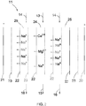
- FIG. 2 illustrates a schematic diagram of a desalination apparatus.
- the desalination apparatus 11 comprises a first electrode 20, a second electrode 21, a plurality of cation exchange membranes 22 and a plurality of spacers 23.
- the first and second electrodes 20, 21 are connected to positive and negative terminals of a power source (not shown) so as to act as an anode and a cathode, respectively.
- the polarity of the first and second electrodes 20, 21 may be reversed.
- the first and second electrodes 20, 21 may include metal materials with different shapes, such as titanium plates or platinum coated titanium plates.
- the first and second electrodes 20, 21 may include electrically conductive materials, which may or may not be thermally conductive, and may have particles with smaller sizes and large surface areas.
- the electrically conductive material may include one or more carbon materials.
- Non-limiting examples of the carbon materials include activated carbon particles, porous carbon particles, carbon fibers, carbon aerogels, porous mesocarbon microbeads, or combinations thereof.
- the electrically conductive materials may include a conductive composite, such as oxides of manganese, or iron, or both, or carbides of titanium, zirconium, vanadium, tungsten, or combinations thereof.
- the first and second electrodes 20, 21 are in the form of plates that are disposed parallel to each other to form a stacked structure.
- the first and second electrodes 20, 21 may have varied shapes, such as a sheet, a block, or a cylinder.
- the first and second electrodes 20, 21 may be arranged in varying configurations.
- the first and second electrodes 20, 21 may be disposed concentrically with a spiral and continuous space therebetween.
- the cation exchange membranes 22 are configured to be passable for cations and are disposed between the first and second electrodes 20, 21 so as to form a plurality of alternating first and second channels 24, 25 therebetween, which are also referred to as dilute and concentrate channels under operating conditions, respectively.
- four cation exchange membranes 22 are employed to form one first channel 24 and two second channels 25, which are disposed alternatingly.
- at least three cation exchange membranes 22 may be employed so as to form one or more first channels and one or more second channels between the first and second electrodes 20, 21.
- the cation exchange membranes 22 may comprise normal cation exchange membranes configured to be passable for not only the monovalent anions but also polyvalent anions.
- the desalination apparatus 11 may comprise one or more monovalent cation exchange membranes.
- the normal cation exchange membranes and the monovalent cation exchange membranes may be disposed alternately to facilitate removal of the hardness ions.
- suitable materials for use in the normal cation exchange membranes include a polymeric material that includes sulfonic acid groups and/or carboxylic acid groups, for transmission of the cations.
- the spacers 23 are disposed between each pair of two adjacent ion exchange membranes 22, and between the first and second electrodes 20, 21 and the respective adjacent membranes 22.
- the spacers 23 may comprise any ion-permeable, electronically nonconductive material, including membranes and porous and nonporous materials.
- liquids, such as the first and second streams 13, 14 are introduced into the first channel 24 and the second channels 25, respectively.
- the first and second stream 13, 14 may or may not be introduced into desalination apparatus 11 simultaneously.
- first and second stream 13, 14 pass through the respective dilute and concentrate channels 24, 25, due to presence of the cation exchange membranes 22, in the dilute channel 24, at least a portion of the target ions, such as Mg 2+ and Ca 2+ , and other cations, such as Na + in the first feed stream 13 may migrate through the respective cation exchange membranes 22 towards the anode 20 to enter into the concentrate channels 25.
- Anions, such as Cl - in the first feed stream 13 may not migrate through the respective anion exchange membrane and remain in the dilute channel 24.
- anions, such as Cl - in the second feed stream 14 may not migrate through the anion exchange membrane 22 and remain therein.
- a portion of the removed target cations, such as Mg 2+ and/or Ca 2+ migrated into the concentrate channels 25 from the first feed stream 13 in the dilute channel 24 and other cations, such as Na+ may further migrate through the cation exchange membranes 22 to enter into the dilute channel(s) 24 from the respective adjacent concentrate channels 25 during operation.
- the second feed stream 14 may include active monovalent cations, such as Na + (which is referred to be as Na + -rich stream), which may carry at least a larger portion of the ionic current than the target ions migrated into the concentrate channels 25 from the dilute channel 24 when the cations migrate from the concentrate channels 25 to the respective dilute channels 24 during operation.
- active monovalent cations such as Na + (which is referred to be as Na + -rich stream)
- a concentration of the active monovalent cations may be greater than a concentration of the removed target ions in the respective concentrate channels 25.
- an ionic mobility of the active monovalent ions may be greater than the ionic mobility of the removed target ions in the respective concentrate channels 25 when migrated from the concentrate channels 25 to the respective dilute channels 24.
- amounts of the active monovalent cations in the second feed stream 14 may be greater than amounts of the removed target ions in the concentrate channels 25 when migrated from the concentrate channels 25 to the respective dilute channels 24.
- the active monovalent cations in the second feed stream 14 in the concentrate channels 25 may migrate through the cation exchange membrane 22 to enter into the adjacent dilute channel 24. Accordingly, during operation, since the active monovalent cations in the second feed stream 14 may carry at least a larger portion of the ionic current than the removed target ions in the concentrate channels 25 when continuing to migrate from the concentrate channels 25 to the respective dilute channels 24 during operation, at least a larger portion of the removed target ions migrated into the concentrate channels 25 from the dilute channels 24 may not migrate through the cation exchange membranes 22 to further enter into the dilute channels 24 to remain in the respective concentrate channels 25 so as to increase the efficiency of the target ions removed from the first feed stream 13.
- the desalination system 10 further comprises an ion adjustment unit 26 in fluid communication with the second feed stream 14 so as to facilitate that the ionic current carried by the active monovalent anions in the second feed stream 14 are greater than the ionic current carried by the target ions in the concentrate channels 25 when migrated from the concentrate channels 25 to the respective dilute channels 24.
- the active monovalent cations may include Na + , K + or H + .
- the ion adjustment unit 26 introduces sodium chloride solution into the second feed stream 14 to increase the concentration of the active monovalent ions, such as sodium ions (Na + ). In certain applications, the ion adjustment unit 26 may or may not be employed.
- the second feed stream 14 passes through the concentrate channels 25 to carry at least a portion of the removed target anions, such as the hardness ions migrated from the dilute channels 24 out of the desalination apparatus 11, so that the first output stream 15 having a suitable level of the hardness ions is then introduced into the EDI apparatus 12 for further processing.
- the polarity of the first and second electrodes 20, 21 of the desalination apparatus 11 may be reversed.
- the dilute channels 24 from the normal polarity state may act as the concentrate channels to receive the second feed stream 14, and the concentrate channels 25 from the normal polarity state may function as the dilute channels to receive the first feed stream 13 for desalination, for example, for removal of the hardness ions in the first feed stream 13 and alleviation of the fouling tendency of the anions and cations in the desalination apparatus 11.
- the desalination apparatus 11 may be employed to remove different target ions using different active cations.
- the target ions to be removed at least include the hardness ions, and the active ions in the second feed stream 14 include Na + .
- the active ions may include, but not limited to K + and H + .
- FIG. 3 is an experimental graph illustrating hardness ion removal efficiency of the desalination apparatus 11 in accordance with one embodiment of the invention.
- the desalination apparatus 11 comprises nine cation exchange membranes 22.
- the DC voltage on the desalination apparatus 11 is about 5 volts.
- the first feed stream 13 having a hardness of about 13ppm is processed to produce the first output stream (product stream) 15 having a hardness of about 3ppm.
- the hardness ions may be removed from the first feed stream and the hardness of the product stream 15 remains around 3ppm during operation, which may indicate the desalination apparatus 11 has a relatively higher and stable remove efficiency of the hardness ions.
- the desalination apparatus 11 and the EDI apparatus 12 are disposed separately.
- the desalination apparatus 11 and the EDI apparatus 12 of the desalination system 10 are disposed unitarily by using a common cathode and a common anode to act as a desalination apparatus 30.
- the same numerals in FIGS. 1-2 and 4 may indicate similar elements. For easy illustration, some elements, for example the ion exchange resin are not illustrated in the arrangement in FIG. 4 .
- the desalination apparatus 30 comprises a first electrode 31, a second electrode 32, a plurality of ion exchange membranes 38, 39, 40, and a plurality of spacers 33.
- the first and second electrodes 31, 32 are connected to positive and negative terminals of a power source (not shown) so as to act as an anode and a cathode, respectively.
- the first and second electrodes 31, 32 may include electrically conductive materials.
- the cathode may include stainless steel.
- the anode may include iridium oxide or platinum coated titanium.
- the first and second electrodes 31, 32 may be in the form of plates that are disposed parallel to each other to form a stacked structure. Alternatively, the electrodes may be arranged in varying configurations. For example, the first and second electrodes 31, 32 may be disposed concentrically with a spiral and continuous space therebetween.
- the ion exchange membranes are divided into first and second groups 36, 37 disposed between the first and second electrodes 31, 32 to form first groups of alternating first and second channels 34-35, and second groups of alternating first and second channels 34'-35' therebetween, which are also referred to as first and second groups of dilute and concentrate channels under operating conditions, respectively.
- each of the first and second groups of the alternating first and second channels may comprises a plurality of the alternating first and second channels.
- the second group 37 is disposed between the first group 36 and the first electrode 31 so that the first channels 34' of the second group of the first and second channels 34'-35' are configured to receive a liquid from the first channel 34 of the first group of the first and second channels 34-35 in the first group 36 from further processing.
- One concentrate channel 35 is formed between the first and second groups 36, 37.
- the second group 37 may be disposed between the first group 36 and the second electrode 32.
- Each of the ion exchange membranes of the first group 36 comprises a cation ion exchange membrane 38.
- the second group 37 comprises a plurality of alternating cation and anion exchange membranes 39, 40 so as to form the second group of the alternating dilute and concentrate channels 34', 35'.
- each of the cation ion exchange membranes 38 of the first group 36 may comprise similar materials to the materials of the cation exchange membrane 22 in FIG. 2 .
- Non-liming examples of the cation and anion exchange membranes 39, 40 of the second group 37 include similar materials to the respective cation and anion exchange membranes in the electrodeionization (EDI) apparatus 12.
- the thickness of the anion exchange membrane 40 adjacent to the first group 36 may be thicker than the thickness of other ion exchange membranes, which are not adjacent to the respective electrodes 31, 32, in the first and second groups 36, 37.
- the thickness of the anion exchange membrane 40 adjacent to the first group 36 may be in a range of from 1mm to 3mm, for example, 2mm.
- the membranes adjacent to the respective first and second electrodes 31, 32 may also have a higher thickness, for example in a range of from 1mm to 3mm, such as 2mm.
- the spacers 33 are disposed between each pair of the adjacent ion exchange membranes, and between the first and second electrodes 31, 32 and the respective adjacent membranes 38, 39.
- the spacers 33 may also comprise any ion-permeable, electronically nonconductive material, including membranes and porous and nonporous materials.
- liquids such as first feed stream 13 is introduced into the first (dilute) channel 34.
- the second feed stream 14 is introduced into the second (concentrated) channels 35 in the first group 36 and between the first and second groups 36, 37 respectively.
- target ions including, but not limited to hardness ions may be removed from the first feed stream 13 to produce a first output stream (a dilute stream) 15.
- the second feed stream 14 carries at least a portion of the target ions removed from the first feed stream 13 out of the desalination device 30 during or after desalination of the first feed stream 13 to produce a second output stream (a concentrate stream) 16.
- the first output stream 15 from the first group 36 is introduced into the dilute channels 34' filled with the ion exchange resin (not shown) of the second group 37 for further removal of the target ions, such as the hardness ions so as to produce a product fluid 17 with a higher quality. Meanwhile, water splitting reactions occur in the ion exchange resin in the dilute channels 34' for regeneration of the ion exchange resin.
- a third stream 18 from a liquid source is introduced into the concentrated channels 35' of the second group 37 to carry the removed ions from the respective dilute channels 34' out of the desalination device 30 so as to produce a concentrate fluid 19.
- the arrangement in FIG. 4 is according to the invention.
- the EDI apparatus 12 is integrated with the desalination apparatus 11 shown in FIG. 1 .
- other desalination apparatuses such as electrodialysis (ED) apparatuses or electrodialysis reversal (EDR) apparatuses may also be disposed unitarily with the desalination apparatus 11 by using a common cathode and a common anode.
- ED electrodialysis
- EDR electrodialysis reversal
- other target ions including, but not limited to the hardness ions may also be removed.
- the polarity of the first and second electrodes 31, 32 may be reversed.
- the desalination apparatus 11 employs the cation ion exchange membranes to process a liquid for removal of the target ions, such as the hardness ions therein, which has stable and relatively higher removal efficiency.
- the target ions such as the hardness ions therein
- the desalination apparatus 11 may be disposed separately from or unitary with the EDI apparatus or other desalination apparatuses, which improves the system flexibility for processing of a liquid.
Landscapes
- Chemical & Material Sciences (AREA)
- Water Supply & Treatment (AREA)
- Engineering & Computer Science (AREA)
- Chemical Kinetics & Catalysis (AREA)
- Life Sciences & Earth Sciences (AREA)
- Hydrology & Water Resources (AREA)
- Environmental & Geological Engineering (AREA)
- Organic Chemistry (AREA)
- Health & Medical Sciences (AREA)
- General Chemical & Material Sciences (AREA)
- Electrochemistry (AREA)
- Analytical Chemistry (AREA)
- Molecular Biology (AREA)
- Urology & Nephrology (AREA)
- Separation Using Semi-Permeable Membranes (AREA)
- Water Treatment By Electricity Or Magnetism (AREA)
Description
- The invention relates generally to desalination systems and methods for pure water production. More particularly, this invention relates to desalination systems and methods using ion exchange membranes for removal of hardness ions for high purity water production.
- Water with high purity are widely used in in many industrial processes, such as in high-pressure boilers in power plants, production of semiconductor elements, production of printed circuit boards, production of integrated circuit, and production of injection water for medical purpose.
- Typically, due to continuous operation, and stable and relatively higher quality of product water, electrodeionization (EDI) apparatuses have been employed for processing such liquid steams, for example for production of pure water. Generally, the EDI apparatuses use conventional electrodialysis systems with ion exchange resin filled therein to process the liquid streams. However, during operation, because polyvalent cations with higher concentration may cause scaling tendency, the EDI apparatuses have a hardness tolerance for the liquid streams to be processed. For example, the hardness tolerance of the EDI apparatuses is about less than lppm, which may need rigorous pretreatment of the liquid streams to decrease the hardness therein before the liquid streams are introduced into the EDI apparatus.
- There have been attempts to pretreat the liquid streams to decrease the hardness therein. For example, reversal osmosis (RO) apparatuses are employed. However, the processing efficiency of the reversal osmosis apparatuses may be relatively lower for decreasing the hardness in the liquid streams to a certain level suitable for the EDI apparatuses. As a result, the processing cost may be increased accordingly.
-
JP 2001 097714 A US 3 893 901 discloses a system for softening a water stream by means of an electrodyaliser comprising a plurality of channels defined by cation exchange membranes.WO 2006/110860 discloses an electrodyaliser comprising a diluting channel defined by a pair of cation exchange membranes and a channel defined by a cation and an anion exchange membrane. - There is a need for new and improved desalination system and method for removal of hardness ions for high purity water production.
- A desalination system is provided in accordance with claim 1.
- Embodiment of the invention further provides a method for removing ions from an aqueous stream according to claim 6, which comprises passing a first feed stream through first channels of a first group of alternating first and second channels defined by a first group of paired cation exchange membranes of a desalination apparatus for removing ions to produce a first output stream, and passing a second feed stream through the second channels of the first group of the alternating first and second channels defined by the first group of the paired cation exchange membranes of the desalination apparatus to carry away ions removed from the first feed stream.
- These and other advantages and features will be better understood from the following detailed description of preferred embodiments of the invention that is provided in connection with the accompanying drawings.
-
-
FIG. 1 is a schematic diagram of a desalination system; -
FIG. 2 is schematic diagram of a desalination apparatus; -
FIG. 3 is an experimental graph illustrating hardness ion removal efficiency of the desalination apparatus in accordance with one embodiment of the invention; and -
FIG. 4 is a schematic diagram of the desalination system in accordance with the invention. - Preferred embodiments of the present disclosure will be described hereinbelow with reference to the accompanying drawing 4. In the following description, well-known functions or constructions are not described in detail to avoid obscuring the disclosure in unnecessary detail.
-
FIG. 1 is a schematic diagram of adesalination system 10. As illustrated inFIG. 1 , thedesalination system 10 comprises adesalination apparatus 11 and an electrodeionization (EDI)apparatus 12 in fluid communication with thedesalination apparatus 11. - In some embodiments, the
desalination apparatus 11 is configured to receive afirst feed stream 13 having salts or other impurities from a first liquid source (not shown) for desalination and to receive asecond feed stream 14 from a second liquid source (not shown) during or after desalination of thefirst feed stream 13 so as to carry charged species or target ions removed from thefirst feed stream 13 out of thedesalination apparatus 11. - In non-limiting examples, the salts in the
first feed stream 13 may include charged ions, such as sodium (Na+), chlorine (Cl-), hardness ions including magnesium (Mg2+) and/or calcium (Ca2+), and/or other ions. In one example, the charged ions in thefirst stream 13 at least include target ions, such as a portion of the hardness ions. - Thus, due to desalination of the
desalination apparatus 11, at least a portion of the charged or target ions including the hardness ions in thefirst feed stream 13 may be removed. As a result, afirst output stream 15 is produced and then may be introduced into theEDI apparatus 12 for further processing, which may be a dilute liquid and have a lower concentration of the charged species, such as the hardness ions as compared to thefirst feed stream 13. Meanwhile, a second output stream (a concentrated stream) 16 is also produced, which has a higher concentration of charged species, such as the hardness ions than thesecond feed stream 14. - In some applications, the
first output stream 15 may be circulated into thedesalination apparatus 11 or introduced into any other suitable desalination apparatuses, such as reversal osmosis apparatuses for further processing to remove the charged ions therein before introduced into theEDI apparatus 12. In certain applications, the EDI apparatus may or may not be employed based on different applications. - As used herein, the term "EDI" means an electrochemical purification process using ion exchange membranes and ion exchange resin to remove target ions or charged species from water or other fluids so as to produce higher quality water, for example, pure or ultrapure water.
- In non-limiting examples, the
EDI apparatus 12 comprises a pair of electrodes configured to act as an anode and a cathode, respectively. A plurality of alternating anion and cation exchange membranes are disposed between the anode and the cathode to form a plurality of alternating first and second channels therebetween, which are also referred to as dilute and concentrate channels under operating conditions. A plurality of spacers are disposed between each pair of the membranes, and between the electrodes and the respective adjacent membranes, which may be similar to the structure of an electrodialysis (ED) apparatus. Similarly, the anion exchange membrane(s) are configured to be passable for anions. The cation exchange membrane(s) are configured to be passable for cations. - In addition, based on different applications, the ion exchange resin may be filled into the first channels or the second channels for facilitation of transportation of ions, enhancing the conductivity between the adjacent ion exchange membranes, and electrochemical splitting of water. In non-limiting examples, the ion exchange resin may be filled into the first (dilute) channels.
- For some arrangements, the electrodes of the
EDI apparatus 12 may be in the form of plates that are disposed parallel to each other to form a stacked structure. Alternatively, the electrodes may be arranged in varying configurations. For example, the electrodes may be disposed concentrically with a spiral and continuous space therebetween. In some applications, the electrodes may include electrically conductive materials. The spacers may comprise any ion-permeable, electronically nonconductive material, including membranes and porous and nonporous materials. - In non-limiting examples, the cathode may include stainless steel. The anode may include iridium oxide or platinum coated titanium. The anion exchange membrane may comprise a polymeric material that includes quaternary amine groups. The cation exchange membrane may comprise a polymeric material that includes sulfonic acid groups and/or carboxylic acid groups. The ion exchange resin may include crosslinked polystyrene or other suitable materials.
- Accordingly, during operation, an electrical current is applied to the
EDI apparatus 12. Thefirst output stream 15 from thedesalination apparatus 11 is introduced into the dilute channels filled with the ion exchange resin for further removal of the target ions, such as the hardness ions therein so as to produce aproduct fluid 17 with a higher quality. Athird stream 18 from a liquid source (not shown) is introduced into the concentrate channels to carry the removed target ions from the respective dilute channels out of theEDI apparatus 12 so as to produce aconcentrate fluid 19. In certain applications, theproduct fluid 17 may be circulated into theEDI apparatus 12 for further processing. - Meanwhile, water splitting reactions occur in the ion exchange resin in the first channels to produce H+ and OH- for regeneration of the ion exchange resin for facilitation of continuous operation. An electrolyte stream (not shown) may pass through surfaces of the electrodes to remove gases, such as hydrogen and chlorine generated during the operation to protect the electrodes.
- Generally, the
EDI apparatus 12 has a hardness tolerance for a liquid to be processed therein. For example, the hardness tolerance of the EDI apparatuses may be about less than 1ppm. In order to decrease the hardness in the liquid to a suitable level so as to alleviate or avoid scaling or fouling tendency in theEDI apparatus 12 during processing, as depicted inFIG. 1 , thedesalination apparatus 11 is employed to pretreat thefirst feed stream 13 so as to produce thefirst output stream 15 having a suitable level of the target ions including, but not limited to the hardness ions. -
FIG. 2 illustrates a schematic diagram of a desalination apparatus. As illustrated inFIG. 2 , thedesalination apparatus 11 comprises afirst electrode 20, asecond electrode 21, a plurality ofcation exchange membranes 22 and a plurality ofspacers 23. In the illustrated example, the first andsecond electrodes second electrodes - In some examples, the first and
second electrodes second electrodes - In the illustrated example, the first and
second electrodes second electrodes second electrodes second electrodes - The
cation exchange membranes 22 are configured to be passable for cations and are disposed between the first andsecond electrodes second channels cation exchange membranes 22 are employed to form onefirst channel 24 and twosecond channels 25, which are disposed alternatingly. Alternatively, at least threecation exchange membranes 22 may be employed so as to form one or more first channels and one or more second channels between the first andsecond electrodes - In some applications, the
cation exchange membranes 22 may comprise normal cation exchange membranes configured to be passable for not only the monovalent anions but also polyvalent anions. In certain applications, based on different applications, for example, for removal of monovalent cations, thedesalination apparatus 11 may comprise one or more monovalent cation exchange membranes. Thus, the normal cation exchange membranes and the monovalent cation exchange membranes may be disposed alternately to facilitate removal of the hardness ions. Non-limiting examples of suitable materials for use in the normal cation exchange membranes include a polymeric material that includes sulfonic acid groups and/or carboxylic acid groups, for transmission of the cations. - The
spacers 23 are disposed between each pair of two adjacention exchange membranes 22, and between the first andsecond electrodes adjacent membranes 22. In some embodiments, thespacers 23 may comprise any ion-permeable, electronically nonconductive material, including membranes and porous and nonporous materials. - Accordingly, during operation, when the
desalination apparatus 11 is at a normal polarity state, while an electrical current is applied to thedesalination apparatus 11, liquids, such as the first andsecond streams first channel 24 and thesecond channels 25, respectively. In certain applications, the first andsecond stream desalination apparatus 11 simultaneously. - During the first and
second stream channels cation exchange membranes 22, in thedilute channel 24, at least a portion of the target ions, such as Mg2+ and Ca2+, and other cations, such as Na+ in thefirst feed stream 13 may migrate through the respectivecation exchange membranes 22 towards theanode 20 to enter into theconcentrate channels 25. Anions, such as Cl- in thefirst feed stream 13 may not migrate through the respective anion exchange membrane and remain in thedilute channel 24. - In the
concentrate channels 25, anions, such as Cl- in thesecond feed stream 14 may not migrate through theanion exchange membrane 22 and remain therein. In certain applications, a portion of the removed target cations, such as Mg2+ and/or Ca2+ migrated into theconcentrate channels 25 from thefirst feed stream 13 in thedilute channel 24 and other cations, such as Na+ may further migrate through thecation exchange membranes 22 to enter into the dilute channel(s) 24 from the respectiveadjacent concentrate channels 25 during operation. - In non-limiting examples, in order to prevent at least a portion of the removed target ions migrated into the
concentrate channels 25 from thedilute channels 24 from entering into thedilute channels 24 so as to enter into thefirst feed stream 13 again, thesecond feed stream 14 may include active monovalent cations, such as Na+ (which is referred to be as Na+-rich stream), which may carry at least a larger portion of the ionic current than the target ions migrated into theconcentrate channels 25 from thedilute channel 24 when the cations migrate from theconcentrate channels 25 to the respectivedilute channels 24 during operation. - In non-limiting examples, a concentration of the active monovalent cations may be greater than a concentration of the removed target ions in the
respective concentrate channels 25. In some examples, an ionic mobility of the active monovalent ions may be greater than the ionic mobility of the removed target ions in therespective concentrate channels 25 when migrated from theconcentrate channels 25 to the respectivedilute channels 24. In other examples, amounts of the active monovalent cations in thesecond feed stream 14 may be greater than amounts of the removed target ions in theconcentrate channels 25 when migrated from theconcentrate channels 25 to the respectivedilute channels 24. - As a result, at least a larger portion of the active monovalent cations in the
second feed stream 14 in theconcentrate channels 25 may migrate through thecation exchange membrane 22 to enter into the adjacentdilute channel 24. Accordingly, during operation, since the active monovalent cations in thesecond feed stream 14 may carry at least a larger portion of the ionic current than the removed target ions in theconcentrate channels 25 when continuing to migrate from theconcentrate channels 25 to the respectivedilute channels 24 during operation, at least a larger portion of the removed target ions migrated into theconcentrate channels 25 from thedilute channels 24 may not migrate through thecation exchange membranes 22 to further enter into thedilute channels 24 to remain in therespective concentrate channels 25 so as to increase the efficiency of the target ions removed from thefirst feed stream 13. - For some arrangements, in order to increase the ionic current carried by the active monovalent cations in the
second feed stream 14 when migrated into thedilute channels 24 from theconcentrate channel 25, as illustrated inFIG.1 , thedesalination system 10 further comprises anion adjustment unit 26 in fluid communication with thesecond feed stream 14 so as to facilitate that the ionic current carried by the active monovalent anions in thesecond feed stream 14 are greater than the ionic current carried by the target ions in theconcentrate channels 25 when migrated from theconcentrate channels 25 to the respectivedilute channels 24. In non-limiting examples, the active monovalent cations may include Na+, K+ or H+. In one example, theion adjustment unit 26 introduces sodium chloride solution into thesecond feed stream 14 to increase the concentration of the active monovalent ions, such as sodium ions (Na+). In certain applications, theion adjustment unit 26 may or may not be employed. - Accordingly, as depicted in
FIG. 2 , during operation, thesecond feed stream 14 passes through theconcentrate channels 25 to carry at least a portion of the removed target anions, such as the hardness ions migrated from thedilute channels 24 out of thedesalination apparatus 11, so that thefirst output stream 15 having a suitable level of the hardness ions is then introduced into theEDI apparatus 12 for further processing. - In some examples, the polarity of the first and
second electrodes desalination apparatus 11 may be reversed. In the reversed polarity state, thedilute channels 24 from the normal polarity state may act as the concentrate channels to receive thesecond feed stream 14, and theconcentrate channels 25 from the normal polarity state may function as the dilute channels to receive thefirst feed stream 13 for desalination, for example, for removal of the hardness ions in thefirst feed stream 13 and alleviation of the fouling tendency of the anions and cations in thedesalination apparatus 11. - It should be noted that the arrangements in
FIG. 2 is merely illustrative. In some applications, thedesalination apparatus 11 may be employed to remove different target ions using different active cations. In the illustrated example, the target ions to be removed at least include the hardness ions, and the active ions in thesecond feed stream 14 include Na+. In other examples, the active ions may include, but not limited to K+ and H+. -
FIG. 3 is an experimental graph illustrating hardness ion removal efficiency of thedesalination apparatus 11 in accordance with one embodiment of the invention. In this experimental example, thedesalination apparatus 11 comprises ninecation exchange membranes 22. The DC voltage on thedesalination apparatus 11 is about 5 volts. As illustrated inFIG. 3 , during continuous processing for about 50 minutes in thedesalination apparatus 11, thefirst feed stream 13 having a hardness of about 13ppm is processed to produce the first output stream (product stream) 15 having a hardness of about 3ppm. - Thus, about 77% of the hardness ions may be removed from the first feed stream and the hardness of the
product stream 15 remains around 3ppm during operation, which may indicate thedesalination apparatus 11 has a relatively higher and stable remove efficiency of the hardness ions. - In the illustrated example in
FIG. 1 , thedesalination apparatus 11 and theEDI apparatus 12 are disposed separately. In the invention, as illustrated inFIG. 4 , thedesalination apparatus 11 and theEDI apparatus 12 of thedesalination system 10 are disposed unitarily by using a common cathode and a common anode to act as adesalination apparatus 30. The same numerals inFIGS. 1-2 and4 may indicate similar elements. For easy illustration, some elements, for example the ion exchange resin are not illustrated in the arrangement inFIG. 4 . - As depicted in
FIG. 4 , thedesalination apparatus 30 comprises afirst electrode 31, asecond electrode 32, a plurality ofion exchange membranes spacers 33. In the illustrated example, the first andsecond electrodes - In some applications, the first and
second electrodes second electrodes second electrodes - In the illustrated example, the ion exchange membranes are divided into first and
second groups second electrodes - The
second group 37 is disposed between thefirst group 36 and thefirst electrode 31 so that the first channels 34' of the second group of the first and second channels 34'-35' are configured to receive a liquid from thefirst channel 34 of the first group of the first and second channels 34-35 in thefirst group 36 from further processing. Oneconcentrate channel 35 is formed between the first andsecond groups second group 37 may be disposed between thefirst group 36 and thesecond electrode 32. Each of the ion exchange membranes of thefirst group 36 comprises a cationion exchange membrane 38. Thesecond group 37 comprises a plurality of alternating cation andanion exchange membranes - In some examples, each of the cation
ion exchange membranes 38 of thefirst group 36 may comprise similar materials to the materials of thecation exchange membrane 22 inFIG. 2 . Non-liming examples of the cation andanion exchange membranes second group 37 include similar materials to the respective cation and anion exchange membranes in the electrodeionization (EDI)apparatus 12. - In certain applications, during operation, in order to protect the ion exchange membrane of the
second group 37, for example, theanion exchange membrane 40, which is disposed adjacent to thefirst group 36 to endure a higher pressure difference, the thickness of theanion exchange membrane 40 adjacent to thefirst group 36 may be thicker than the thickness of other ion exchange membranes, which are not adjacent to therespective electrodes second groups anion exchange membrane 40 adjacent to thefirst group 36 may be in a range of from 1mm to 3mm, for example, 2mm. In other examples, the membranes adjacent to the respective first andsecond electrodes - The
spacers 33 are disposed between each pair of the adjacent ion exchange membranes, and between the first andsecond electrodes adjacent membranes spacers 33 may also comprise any ion-permeable, electronically nonconductive material, including membranes and porous and nonporous materials. - Accordingly, similar to the arrangements in
FIG. 2 , during operation, while an electrical current is applied to thedesalination apparatus 30, liquids, such asfirst feed stream 13 is introduced into the first (dilute)channel 34. Thesecond feed stream 14 is introduced into the second (concentrated)channels 35 in thefirst group 36 and between the first andsecond groups first feed stream 13 to produce a first output stream (a dilute stream) 15. Thesecond feed stream 14 carries at least a portion of the target ions removed from thefirst feed stream 13 out of thedesalination device 30 during or after desalination of thefirst feed stream 13 to produce a second output stream (a concentrate stream) 16. - Subsequently, similar to the
EDI apparatus 12 shown inFIG. 1 , thefirst output stream 15 from thefirst group 36 is introduced into the dilute channels 34' filled with the ion exchange resin (not shown) of thesecond group 37 for further removal of the target ions, such as the hardness ions so as to produce aproduct fluid 17 with a higher quality. Meanwhile, water splitting reactions occur in the ion exchange resin in the dilute channels 34' for regeneration of the ion exchange resin. Athird stream 18 from a liquid source (not shown) is introduced into the concentrated channels 35' of thesecond group 37 to carry the removed ions from the respective dilute channels 34' out of thedesalination device 30 so as to produce aconcentrate fluid 19. - It should be noted that the arrangement in
FIG. 4 is according to the invention. In the illustrated example, theEDI apparatus 12 is integrated with thedesalination apparatus 11 shown inFIG. 1 . Alternatively, other desalination apparatuses, such as electrodialysis (ED) apparatuses or electrodialysis reversal (EDR) apparatuses may also be disposed unitarily with thedesalination apparatus 11 by using a common cathode and a common anode. Similarly, other target ions, including, but not limited to the hardness ions may also be removed. In some examples, the polarity of the first andsecond electrodes - In embodiments of the invention, the
desalination apparatus 11 employs the cation ion exchange membranes to process a liquid for removal of the target ions, such as the hardness ions therein, which has stable and relatively higher removal efficiency. As a result, when the liquid having a suitable concentration level of the target ions is introduced into the EDI apparatus for further processing, the scaling or fouling issues may be avoided or alleviated so that the EDI apparatus sustains a continuous and stable operation. In addition, thedesalination apparatus 11 may be disposed separately from or unitary with the EDI apparatus or other desalination apparatuses, which improves the system flexibility for processing of a liquid.
Claims (7)
- A desalination system (10), comprising:a desalination apparatus (30) comprising:first and second electrodes (31,32);a first group of paired ion exchange membranes (36) disposed between the first and second electrodes (31,32) to form a first group of alternating first and second channels (34,35), the first channels (34) configured to receive a first feed stream (13) for desalination and the second channels (35) configured to receive a second feed stream (14) to carry away ions removed from the first feed stream, respectively;a plurality of spacers (33) disposed between each pair of the adjacent ion exchange membranes and between the first and second electrodes and the respective ion exchange membranes; andwherein each of the ion exchange membranes in the first group is a cation exchange membrane,wherein the desalination apparatus (30) further comprises a second group (37) of the paired ion exchange membranes disposed between the first group (36) of the ion exchange membranes and at least one of the first and second electrodes (31,32) to form a second group of the alternating first and second channels (34',35'), and wherein the second group of the ion exchange membranes comprises a plurality of alternating cation and anion exchange membranes;wherein the desalination apparatus (30) further comprises ion exchange resin filled into the first channels (34') of the second group of the alternating first and second channels;wherein the first channels (34') of the second group of the alternating first and second channels are configured to receive a liquid from the first channels of the first group of the alternating first and second channels.
- The desalination system (10) of claim 1, the cation exchanges membranes (38) in the first group of the paired ion exchange membranes comprise alternating normal cation exchange membranes and monovalent cation exchange membranes.
- The desalination system (10) of claim 1, further comprising an ion adjustment unit (26) in fluid communication with the desalination apparatus (30) and configured to increase amounts of the active ions in the second feed stream.
- The desalination system (10) of claim 3, wherein the ion adjustment unit (26) is configured to introduce sodium chloride solution into the second feed stream (14) to increase the amounts of the active ions.
- The desalination system (10) of claim 1, wherein the desalination apparatus (30) is configured to remove at least a portion of hardness ions in the first feed stream (13).
- A method for removing ions from an aqueous stream, comprising:passing a first feed stream (13) through first channels (34) of a first group of alternating first and second channels (34,35) defined by a first group of paired cation exchange membranes (38) of a desalination apparatus (30) for removing at least a portion of cations to produce a first output stream (15); andpassing a second feed stream (14) through the second channels (35) of the first group of the alternating first and second channels defined by the first group of the paired cation exchange membranes (38) of the desalination apparatus (30) to carry away the at least a portion of the cations removed from the first feed stream, wherein the desalination apparatus (30) comprises:first and second electrodes (31,32);the first group of the paired cation exchange membranes (38) disposed between the first and second electrodes (31,32) to form the first group of the alternating first and second channels; anda plurality of spacers (33) disposed between each pair of adjacent ion exchange membranes and between the first and second electrodes and the respective ion exchange membranes; andwherein the desalination apparatus (30) further comprises a second group (37) of paired ion exchange membranes disposed between the first group (36) of the cation exchange membranes and at least one of the first and second electrodes (31,32) to form a second group of the alternating first and second channels (34',35'), and wherein the second group of the ion exchange membranes comprises a plurality of alternating cation and anion exchange membraneswherein the desalination apparatus (11) further comprises ion exchange resin filled into the first channels of the second group of the alternating first and second channels andpassing the first output stream (15) through first channels (34') of a second group of the alternating first and second channels defined by a second group of paired ion exchange membranes of the desalination apparatus for ion removal; andpassing a third stream (18) through the second channels (35') of the second group of the alternating first and second channels defined by the second group of the paired ion exchange membranes of the desalination apparatus to carry away ions removed from the first output stream..
- The desalination method of claim 6, further comprising increasing amounts of active cations in the second feed stream (14) before the second feed stream is introduced into the desalination apparatus (30).
Applications Claiming Priority (2)
| Application Number | Priority Date | Filing Date | Title |
|---|---|---|---|
| CN201110265274.XA CN102992522B (en) | 2011-09-08 | 2011-09-08 | Desalination system and method |
| PCT/US2012/050508 WO2013036353A1 (en) | 2011-09-08 | 2012-08-13 | Desalination system and method |
Publications (2)
| Publication Number | Publication Date |
|---|---|
| EP2753585A1 EP2753585A1 (en) | 2014-07-16 |
| EP2753585B1 true EP2753585B1 (en) | 2021-02-17 |
Family
ID=46690760
Family Applications (1)
| Application Number | Title | Priority Date | Filing Date |
|---|---|---|---|
| EP12748363.4A Active EP2753585B1 (en) | 2011-09-08 | 2012-08-13 | Desalination system and method |
Country Status (12)
| Country | Link |
|---|---|
| US (1) | US9481586B2 (en) |
| EP (1) | EP2753585B1 (en) |
| JP (1) | JP6148675B2 (en) |
| KR (1) | KR101787181B1 (en) |
| CN (1) | CN102992522B (en) |
| AU (1) | AU2012304860B2 (en) |
| CA (1) | CA2847306C (en) |
| DK (1) | DK2753585T3 (en) |
| ES (1) | ES2864854T3 (en) |
| SG (2) | SG11201400342QA (en) |
| TW (1) | TWI561475B (en) |
| WO (1) | WO2013036353A1 (en) |
Families Citing this family (5)
| Publication number | Priority date | Publication date | Assignee | Title |
|---|---|---|---|---|
| US9845252B2 (en) | 2013-06-19 | 2017-12-19 | Massachusetts Institute Of Technology | Water desalination/purification and bio-agent preconcentration by ion concentration polarization |
| US9850146B2 (en) | 2013-06-19 | 2017-12-26 | Massachusetts Institute Of Technology | Ion concentration polarization-electrocoagulation hybrid water treatment system |
| US9964510B2 (en) | 2013-09-16 | 2018-05-08 | Dionex Corporation | Electrolytic four-channel device and method |
| CN113493259A (en) * | 2020-04-01 | 2021-10-12 | 佛山市云米电器科技有限公司 | Household water purifying device |
| KR20250108446A (en) * | 2024-01-08 | 2025-07-15 | 삼성전자주식회사 | Electrodes for cdi, water treatment apparatus including electrodes for cdi and manufacturing method for electrodes for cdi |
Family Cites Families (14)
| Publication number | Priority date | Publication date | Assignee | Title |
|---|---|---|---|---|
| US3893901A (en) * | 1973-12-04 | 1975-07-08 | Vast Associates Inc J | System for softening and dealkalizing water by electrodialysis |
| JPH08108184A (en) | 1994-10-13 | 1996-04-30 | Hitachi Ltd | Water treatment system |
| US5645703A (en) * | 1995-12-20 | 1997-07-08 | University Of Chicago | Electrodialysis-based separation process for salt recovery and recycling from waste water |
| US6402917B1 (en) * | 1998-02-09 | 2002-06-11 | Otv Societe Anonyme | Electrodialysis apparatus |
| US6149788A (en) | 1998-10-16 | 2000-11-21 | E-Cell Corporation | Method and apparatus for preventing scaling in electrodeionization units |
| JP3113249B1 (en) * | 1999-10-01 | 2000-11-27 | 強化土エンジニヤリング株式会社 | Method for producing alkali-free water glass |
| EP1129765A1 (en) | 2000-03-02 | 2001-09-05 | Asahi Glass Company Ltd. | Method for producing deionized water |
| US6274019B1 (en) | 2000-03-08 | 2001-08-14 | Organo Corporation | Electrodeionization apparatus |
| EP1456132B1 (en) | 2001-12-20 | 2014-01-22 | Aquatech International Corporation | Fractional deionization process |
| US20060231403A1 (en) * | 2005-04-14 | 2006-10-19 | Riviello John M | Chambered electrodeionization apparatus with uniform current density, and method of use |
| JP4915843B2 (en) | 2006-05-11 | 2012-04-11 | オルガノ株式会社 | Electric softening device, softening device and soft water production method |
| CN101795752B (en) | 2007-07-19 | 2012-12-05 | 国际壳牌研究有限公司 | Water processing systems and methods |
| CN101306855B (en) | 2007-11-07 | 2010-07-21 | 傅叶明 | Plate type electro-deionization device |
| JP5295927B2 (en) | 2009-10-23 | 2013-09-18 | オルガノ株式会社 | Electric deionized water production equipment |
-
2011
- 2011-09-08 CN CN201110265274.XA patent/CN102992522B/en active Active
-
2012
- 2012-08-13 US US14/342,936 patent/US9481586B2/en active Active
- 2012-08-13 CA CA2847306A patent/CA2847306C/en active Active
- 2012-08-13 EP EP12748363.4A patent/EP2753585B1/en active Active
- 2012-08-13 JP JP2014529728A patent/JP6148675B2/en active Active
- 2012-08-13 SG SG11201400342QA patent/SG11201400342QA/en unknown
- 2012-08-13 DK DK12748363.4T patent/DK2753585T3/en active
- 2012-08-13 AU AU2012304860A patent/AU2012304860B2/en active Active
- 2012-08-13 KR KR1020147006066A patent/KR101787181B1/en active Active
- 2012-08-13 WO PCT/US2012/050508 patent/WO2013036353A1/en not_active Ceased
- 2012-08-13 SG SG10201509606TA patent/SG10201509606TA/en unknown
- 2012-08-13 ES ES12748363T patent/ES2864854T3/en active Active
- 2012-08-31 TW TW101131929A patent/TWI561475B/en active
Non-Patent Citations (1)
| Title |
|---|
| None * |
Also Published As
| Publication number | Publication date |
|---|---|
| DK2753585T3 (en) | 2021-04-19 |
| CA2847306C (en) | 2017-09-05 |
| JP6148675B2 (en) | 2017-06-14 |
| SG10201509606TA (en) | 2015-12-30 |
| KR101787181B1 (en) | 2017-10-18 |
| ES2864854T3 (en) | 2021-10-14 |
| AU2012304860A1 (en) | 2014-03-20 |
| JP2014528824A (en) | 2014-10-30 |
| CN102992522B (en) | 2014-10-15 |
| SG11201400342QA (en) | 2014-03-28 |
| CA2847306A1 (en) | 2013-03-14 |
| TWI561475B (en) | 2016-12-11 |
| US20140209462A1 (en) | 2014-07-31 |
| WO2013036353A1 (en) | 2013-03-14 |
| US9481586B2 (en) | 2016-11-01 |
| EP2753585A1 (en) | 2014-07-16 |
| CN102992522A (en) | 2013-03-27 |
| KR20140060298A (en) | 2014-05-19 |
| AU2012304860B2 (en) | 2016-10-13 |
| TW201326052A (en) | 2013-07-01 |
Similar Documents
| Publication | Publication Date | Title |
|---|---|---|
| US20190330087A1 (en) | Desalination system and method | |
| US20110024354A1 (en) | Desalination system and method | |
| CA2847306C (en) | Desalination system and method | |
| KR102186074B1 (en) | Concentration method of lithium by electrodialysis | |
| EP2825509B1 (en) | Desalination method | |
| WO2013009485A1 (en) | Desalination systems and methods | |
| WO2013036354A1 (en) | Desalination system and method | |
| US20210198126A1 (en) | Electrodialysis process for high ion rejection in the presence of boron | |
| CN103787532A (en) | System and method for reducing fluid chemical oxygen demand |
Legal Events
| Date | Code | Title | Description |
|---|---|---|---|
| PUAI | Public reference made under article 153(3) epc to a published international application that has entered the european phase |
Free format text: ORIGINAL CODE: 0009012 |
|
| 17P | Request for examination filed |
Effective date: 20140408 |
|
| AK | Designated contracting states |
Kind code of ref document: A1 Designated state(s): AL AT BE BG CH CY CZ DE DK EE ES FI FR GB GR HR HU IE IS IT LI LT LU LV MC MK MT NL NO PL PT RO RS SE SI SK SM TR |
|
| DAX | Request for extension of the european patent (deleted) | ||
| 17Q | First examination report despatched |
Effective date: 20160727 |
|
| STAA | Information on the status of an ep patent application or granted ep patent |
Free format text: STATUS: EXAMINATION IS IN PROGRESS |
|
| RAP1 | Party data changed (applicant data changed or rights of an application transferred) |
Owner name: BL TECHNOLOGIES, INC. |
|
| GRAP | Despatch of communication of intention to grant a patent |
Free format text: ORIGINAL CODE: EPIDOSNIGR1 |
|
| STAA | Information on the status of an ep patent application or granted ep patent |
Free format text: STATUS: GRANT OF PATENT IS INTENDED |
|
| INTG | Intention to grant announced |
Effective date: 20200724 |
|
| GRAJ | Information related to disapproval of communication of intention to grant by the applicant or resumption of examination proceedings by the epo deleted |
Free format text: ORIGINAL CODE: EPIDOSDIGR1 |
|
| STAA | Information on the status of an ep patent application or granted ep patent |
Free format text: STATUS: EXAMINATION IS IN PROGRESS |
|
| GRAS | Grant fee paid |
Free format text: ORIGINAL CODE: EPIDOSNIGR3 |
|
| STAA | Information on the status of an ep patent application or granted ep patent |
Free format text: STATUS: GRANT OF PATENT IS INTENDED |
|
| GRAP | Despatch of communication of intention to grant a patent |
Free format text: ORIGINAL CODE: EPIDOSNIGR1 |
|
| INTC | Intention to grant announced (deleted) | ||
| GRAA | (expected) grant |
Free format text: ORIGINAL CODE: 0009210 |
|
| STAA | Information on the status of an ep patent application or granted ep patent |
Free format text: STATUS: THE PATENT HAS BEEN GRANTED |
|
| INTG | Intention to grant announced |
Effective date: 20201223 |
|
| AK | Designated contracting states |
Kind code of ref document: B1 Designated state(s): AL AT BE BG CH CY CZ DE DK EE ES FI FR GB GR HR HU IE IS IT LI LT LU LV MC MK MT NL NO PL PT RO RS SE SI SK SM TR |
|
| REG | Reference to a national code |
Ref country code: GB Ref legal event code: FG4D |
|
| REG | Reference to a national code |
Ref country code: CH Ref legal event code: EP |
|
| REG | Reference to a national code |
Ref country code: DE Ref legal event code: R096 Ref document number: 602012074381 Country of ref document: DE |
|
| REG | Reference to a national code |
Ref country code: AT Ref legal event code: REF Ref document number: 1361236 Country of ref document: AT Kind code of ref document: T Effective date: 20210315 |
|
| REG | Reference to a national code |
Ref country code: IE Ref legal event code: FG4D |
|
| REG | Reference to a national code |
Ref country code: DK Ref legal event code: T3 Effective date: 20210412 |
|
| REG | Reference to a national code |
Ref country code: NL Ref legal event code: FP |
|
| REG | Reference to a national code |
Ref country code: LT Ref legal event code: MG9D |
|
| PG25 | Lapsed in a contracting state [announced via postgrant information from national office to epo] |
Ref country code: PT Free format text: LAPSE BECAUSE OF FAILURE TO SUBMIT A TRANSLATION OF THE DESCRIPTION OR TO PAY THE FEE WITHIN THE PRESCRIBED TIME-LIMIT Effective date: 20210617 Ref country code: LT Free format text: LAPSE BECAUSE OF FAILURE TO SUBMIT A TRANSLATION OF THE DESCRIPTION OR TO PAY THE FEE WITHIN THE PRESCRIBED TIME-LIMIT Effective date: 20210217 Ref country code: FI Free format text: LAPSE BECAUSE OF FAILURE TO SUBMIT A TRANSLATION OF THE DESCRIPTION OR TO PAY THE FEE WITHIN THE PRESCRIBED TIME-LIMIT Effective date: 20210217 Ref country code: HR Free format text: LAPSE BECAUSE OF FAILURE TO SUBMIT A TRANSLATION OF THE DESCRIPTION OR TO PAY THE FEE WITHIN THE PRESCRIBED TIME-LIMIT Effective date: 20210217 Ref country code: GR Free format text: LAPSE BECAUSE OF FAILURE TO SUBMIT A TRANSLATION OF THE DESCRIPTION OR TO PAY THE FEE WITHIN THE PRESCRIBED TIME-LIMIT Effective date: 20210518 Ref country code: BG Free format text: LAPSE BECAUSE OF FAILURE TO SUBMIT A TRANSLATION OF THE DESCRIPTION OR TO PAY THE FEE WITHIN THE PRESCRIBED TIME-LIMIT Effective date: 20210517 Ref country code: NO Free format text: LAPSE BECAUSE OF FAILURE TO SUBMIT A TRANSLATION OF THE DESCRIPTION OR TO PAY THE FEE WITHIN THE PRESCRIBED TIME-LIMIT Effective date: 20210517 |
|
| REG | Reference to a national code |
Ref country code: AT Ref legal event code: MK05 Ref document number: 1361236 Country of ref document: AT Kind code of ref document: T Effective date: 20210217 |
|
| PG25 | Lapsed in a contracting state [announced via postgrant information from national office to epo] |
Ref country code: RS Free format text: LAPSE BECAUSE OF FAILURE TO SUBMIT A TRANSLATION OF THE DESCRIPTION OR TO PAY THE FEE WITHIN THE PRESCRIBED TIME-LIMIT Effective date: 20210217 Ref country code: PL Free format text: LAPSE BECAUSE OF FAILURE TO SUBMIT A TRANSLATION OF THE DESCRIPTION OR TO PAY THE FEE WITHIN THE PRESCRIBED TIME-LIMIT Effective date: 20210217 Ref country code: LV Free format text: LAPSE BECAUSE OF FAILURE TO SUBMIT A TRANSLATION OF THE DESCRIPTION OR TO PAY THE FEE WITHIN THE PRESCRIBED TIME-LIMIT Effective date: 20210217 Ref country code: SE Free format text: LAPSE BECAUSE OF FAILURE TO SUBMIT A TRANSLATION OF THE DESCRIPTION OR TO PAY THE FEE WITHIN THE PRESCRIBED TIME-LIMIT Effective date: 20210217 |
|
| PG25 | Lapsed in a contracting state [announced via postgrant information from national office to epo] |
Ref country code: IS Free format text: LAPSE BECAUSE OF FAILURE TO SUBMIT A TRANSLATION OF THE DESCRIPTION OR TO PAY THE FEE WITHIN THE PRESCRIBED TIME-LIMIT Effective date: 20210617 |
|
| REG | Reference to a national code |
Ref country code: ES Ref legal event code: FG2A Ref document number: 2864854 Country of ref document: ES Kind code of ref document: T3 Effective date: 20211014 |
|
| PG25 | Lapsed in a contracting state [announced via postgrant information from national office to epo] |
Ref country code: SM Free format text: LAPSE BECAUSE OF FAILURE TO SUBMIT A TRANSLATION OF THE DESCRIPTION OR TO PAY THE FEE WITHIN THE PRESCRIBED TIME-LIMIT Effective date: 20210217 Ref country code: AT Free format text: LAPSE BECAUSE OF FAILURE TO SUBMIT A TRANSLATION OF THE DESCRIPTION OR TO PAY THE FEE WITHIN THE PRESCRIBED TIME-LIMIT Effective date: 20210217 Ref country code: EE Free format text: LAPSE BECAUSE OF FAILURE TO SUBMIT A TRANSLATION OF THE DESCRIPTION OR TO PAY THE FEE WITHIN THE PRESCRIBED TIME-LIMIT Effective date: 20210217 |
|
| REG | Reference to a national code |
Ref country code: DE Ref legal event code: R097 Ref document number: 602012074381 Country of ref document: DE |
|
| PG25 | Lapsed in a contracting state [announced via postgrant information from national office to epo] |
Ref country code: SK Free format text: LAPSE BECAUSE OF FAILURE TO SUBMIT A TRANSLATION OF THE DESCRIPTION OR TO PAY THE FEE WITHIN THE PRESCRIBED TIME-LIMIT Effective date: 20210217 Ref country code: RO Free format text: LAPSE BECAUSE OF FAILURE TO SUBMIT A TRANSLATION OF THE DESCRIPTION OR TO PAY THE FEE WITHIN THE PRESCRIBED TIME-LIMIT Effective date: 20210217 |
|
| PLBE | No opposition filed within time limit |
Free format text: ORIGINAL CODE: 0009261 |
|
| STAA | Information on the status of an ep patent application or granted ep patent |
Free format text: STATUS: NO OPPOSITION FILED WITHIN TIME LIMIT |
|
| 26N | No opposition filed |
Effective date: 20211118 |
|
| PG25 | Lapsed in a contracting state [announced via postgrant information from national office to epo] |
Ref country code: AL Free format text: LAPSE BECAUSE OF FAILURE TO SUBMIT A TRANSLATION OF THE DESCRIPTION OR TO PAY THE FEE WITHIN THE PRESCRIBED TIME-LIMIT Effective date: 20210217 |
|
| PG25 | Lapsed in a contracting state [announced via postgrant information from national office to epo] |
Ref country code: SI Free format text: LAPSE BECAUSE OF FAILURE TO SUBMIT A TRANSLATION OF THE DESCRIPTION OR TO PAY THE FEE WITHIN THE PRESCRIBED TIME-LIMIT Effective date: 20210217 |
|
| REG | Reference to a national code |
Ref country code: CH Ref legal event code: PL |
|
| PG25 | Lapsed in a contracting state [announced via postgrant information from national office to epo] |
Ref country code: MC Free format text: LAPSE BECAUSE OF FAILURE TO SUBMIT A TRANSLATION OF THE DESCRIPTION OR TO PAY THE FEE WITHIN THE PRESCRIBED TIME-LIMIT Effective date: 20210217 |
|
| REG | Reference to a national code |
Ref country code: BE Ref legal event code: MM Effective date: 20210831 |
|
| GBPC | Gb: european patent ceased through non-payment of renewal fee |
Effective date: 20210813 |
|
| PG25 | Lapsed in a contracting state [announced via postgrant information from national office to epo] |
Ref country code: LI Free format text: LAPSE BECAUSE OF NON-PAYMENT OF DUE FEES Effective date: 20210831 Ref country code: CH Free format text: LAPSE BECAUSE OF NON-PAYMENT OF DUE FEES Effective date: 20210831 |
|
| PG25 | Lapsed in a contracting state [announced via postgrant information from national office to epo] |
Ref country code: IS Free format text: LAPSE BECAUSE OF FAILURE TO SUBMIT A TRANSLATION OF THE DESCRIPTION OR TO PAY THE FEE WITHIN THE PRESCRIBED TIME-LIMIT Effective date: 20210617 Ref country code: LU Free format text: LAPSE BECAUSE OF NON-PAYMENT OF DUE FEES Effective date: 20210813 |
|
| PG25 | Lapsed in a contracting state [announced via postgrant information from national office to epo] |
Ref country code: IE Free format text: LAPSE BECAUSE OF NON-PAYMENT OF DUE FEES Effective date: 20210813 Ref country code: GB Free format text: LAPSE BECAUSE OF NON-PAYMENT OF DUE FEES Effective date: 20210813 Ref country code: BE Free format text: LAPSE BECAUSE OF NON-PAYMENT OF DUE FEES Effective date: 20210831 |
|
| REG | Reference to a national code |
Ref country code: FR Ref legal event code: PLFP Year of fee payment: 11 |
|
| PG25 | Lapsed in a contracting state [announced via postgrant information from national office to epo] |
Ref country code: HU Free format text: LAPSE BECAUSE OF FAILURE TO SUBMIT A TRANSLATION OF THE DESCRIPTION OR TO PAY THE FEE WITHIN THE PRESCRIBED TIME-LIMIT; INVALID AB INITIO Effective date: 20120813 Ref country code: CY Free format text: LAPSE BECAUSE OF FAILURE TO SUBMIT A TRANSLATION OF THE DESCRIPTION OR TO PAY THE FEE WITHIN THE PRESCRIBED TIME-LIMIT Effective date: 20210217 |
|
| P01 | Opt-out of the competence of the unified patent court (upc) registered |
Effective date: 20230521 |
|
| PG25 | Lapsed in a contracting state [announced via postgrant information from national office to epo] |
Ref country code: MK Free format text: LAPSE BECAUSE OF FAILURE TO SUBMIT A TRANSLATION OF THE DESCRIPTION OR TO PAY THE FEE WITHIN THE PRESCRIBED TIME-LIMIT Effective date: 20210217 |
|
| PG25 | Lapsed in a contracting state [announced via postgrant information from national office to epo] |
Ref country code: TR Free format text: LAPSE BECAUSE OF FAILURE TO SUBMIT A TRANSLATION OF THE DESCRIPTION OR TO PAY THE FEE WITHIN THE PRESCRIBED TIME-LIMIT Effective date: 20210217 |
|
| PG25 | Lapsed in a contracting state [announced via postgrant information from national office to epo] |
Ref country code: MT Free format text: LAPSE BECAUSE OF FAILURE TO SUBMIT A TRANSLATION OF THE DESCRIPTION OR TO PAY THE FEE WITHIN THE PRESCRIBED TIME-LIMIT Effective date: 20210217 |
|
| PGFP | Annual fee paid to national office [announced via postgrant information from national office to epo] |
Ref country code: NL Payment date: 20250826 Year of fee payment: 14 |
|
| PGFP | Annual fee paid to national office [announced via postgrant information from national office to epo] |
Ref country code: ES Payment date: 20250901 Year of fee payment: 14 |
|
| PGFP | Annual fee paid to national office [announced via postgrant information from national office to epo] |
Ref country code: DK Payment date: 20250825 Year of fee payment: 14 Ref country code: DE Payment date: 20250827 Year of fee payment: 14 |
|
| PGFP | Annual fee paid to national office [announced via postgrant information from national office to epo] |
Ref country code: IT Payment date: 20250820 Year of fee payment: 14 |
|
| PGFP | Annual fee paid to national office [announced via postgrant information from national office to epo] |
Ref country code: FR Payment date: 20250825 Year of fee payment: 14 |
|
| PGFP | Annual fee paid to national office [announced via postgrant information from national office to epo] |
Ref country code: CZ Payment date: 20250724 Year of fee payment: 14 |