EP2753391B1 - Shuttling by-pass compressor apparatus - Google Patents
Shuttling by-pass compressor apparatus Download PDFInfo
- Publication number
- EP2753391B1 EP2753391B1 EP12830772.5A EP12830772A EP2753391B1 EP 2753391 B1 EP2753391 B1 EP 2753391B1 EP 12830772 A EP12830772 A EP 12830772A EP 2753391 B1 EP2753391 B1 EP 2753391B1
- Authority
- EP
- European Patent Office
- Prior art keywords
- compressor head
- compressor
- gas flow
- head
- flow
- Prior art date
- Legal status (The legal status is an assumption and is not a legal conclusion. Google has not performed a legal analysis and makes no representation as to the accuracy of the status listed.)
- Active
Links
Images


Classifications
-
- F—MECHANICAL ENGINEERING; LIGHTING; HEATING; WEAPONS; BLASTING
- F04—POSITIVE - DISPLACEMENT MACHINES FOR LIQUIDS; PUMPS FOR LIQUIDS OR ELASTIC FLUIDS
- F04B—POSITIVE-DISPLACEMENT MACHINES FOR LIQUIDS; PUMPS
- F04B45/00—Pumps or pumping installations having flexible working members and specially adapted for elastic fluids
- F04B45/04—Pumps or pumping installations having flexible working members and specially adapted for elastic fluids having plate-like flexible members, e.g. diaphragms
- F04B45/043—Pumps or pumping installations having flexible working members and specially adapted for elastic fluids having plate-like flexible members, e.g. diaphragms two or more plate-like pumping flexible members in parallel
-
- F—MECHANICAL ENGINEERING; LIGHTING; HEATING; WEAPONS; BLASTING
- F04—POSITIVE - DISPLACEMENT MACHINES FOR LIQUIDS; PUMPS FOR LIQUIDS OR ELASTIC FLUIDS
- F04B—POSITIVE-DISPLACEMENT MACHINES FOR LIQUIDS; PUMPS
- F04B45/00—Pumps or pumping installations having flexible working members and specially adapted for elastic fluids
- F04B45/04—Pumps or pumping installations having flexible working members and specially adapted for elastic fluids having plate-like flexible members, e.g. diaphragms
- F04B45/047—Pumps having electric drive
-
- F—MECHANICAL ENGINEERING; LIGHTING; HEATING; WEAPONS; BLASTING
- F04—POSITIVE - DISPLACEMENT MACHINES FOR LIQUIDS; PUMPS FOR LIQUIDS OR ELASTIC FLUIDS
- F04B—POSITIVE-DISPLACEMENT MACHINES FOR LIQUIDS; PUMPS
- F04B2207/00—External parameters
- F04B2207/04—Settings
- F04B2207/041—Settings of flow
-
- Y—GENERAL TAGGING OF NEW TECHNOLOGICAL DEVELOPMENTS; GENERAL TAGGING OF CROSS-SECTIONAL TECHNOLOGIES SPANNING OVER SEVERAL SECTIONS OF THE IPC; TECHNICAL SUBJECTS COVERED BY FORMER USPC CROSS-REFERENCE ART COLLECTIONS [XRACs] AND DIGESTS
- Y10—TECHNICAL SUBJECTS COVERED BY FORMER USPC
- Y10T—TECHNICAL SUBJECTS COVERED BY FORMER US CLASSIFICATION
- Y10T29/00—Metal working
- Y10T29/49—Method of mechanical manufacture
- Y10T29/49229—Prime mover or fluid pump making
- Y10T29/49236—Fluid pump or compressor making
Definitions
- This document relates to a compressor apparatus for providing compressed gas, and in particular to a shuttling by-pass compressor apparatus used with a ventilator system to achieve steady flow rates using less power.
- the ventilator may include a prior art compressor apparatus that draws in gas and delivers compressed gas to the patient in a controlled manner to meet patient specifications.
- the prior art compressor apparatus 10 may include a pair of compressor heads 12 and 14 that are synchronized to draw in and force out gas in an alternating fashion such that there is a continuous inflow and outflow of gases from the prior art compressor apparatus 10.
- each of the compressor heads 12 and 14 further includes a respective intake chamber 16A and 16B in selective communication with a respective inlet port 18A and 18B for the entry of gas, such as air, oxygen or a mixture of gases, which then flows into a respective cavity 17A and 17B through a one-way intake valve (not shown).
- the cavity is configured such that the gas flow from the respective intake chamber 16A and 16B can be compressed and forced from the cavity 17A and 17B of each compressor head 12 and 14 and into an exhaust chamber 20A and 20B through a one-way exhaust valve (not shown), which then allows the compressed gas to exit the compressor heads 12 and 14 through a respective outlet port 22A and 22B.
- the gas is drawn in, compressed, and forced from the cavity through the exhaust valve by a flexible diaphragm or piston (not shown) driven against the cavity in a reciprocating motion that draws in and forces out the gas flow from the cavity for delivery to the patient at a predetermined flow rate through an output connector 24.
- a flexible diaphragm or piston (not shown) driven against the cavity in a reciprocating motion that draws in and forces out the gas flow from the cavity for delivery to the patient at a predetermined flow rate through an output connector 24.
- the prior art compressor apparatus 10 cannot achieve steady state flow of gas at flow rates under 3 liters per minute or the compressor apparatus 10 can stall since the compressor apparatus 10 cannot achieve sufficiently low revolutions per minute by a standard motor used normally for compressor apparatuses 10 that drives each compressor head 12 and 14.
- standard compressors are limited in the ratio of minimum flow to maximum flow, which is typically less than 100 to 1. As such, there is a need in the art for a compressor apparatus that permits a steady flow of gases at higher and lower flow rates.
- FR2733688 describes a compressor apparatus wherein the gas flow is controlled by an electromagnetically actuated membrane.
- the compressor comprises a casing which contains two chambers of variable volume having a guide shaft which passes through a soft iron core placed coaxially at the center of an annular magnet.
- Each end of the guide shaft bears a rigid circular plate fitted with an annular membrane, the periphery of which is fastened to the inner wall of the casing, thus defining the two chambers inside the casing.
- the respective volumes of the two chambers vary according to the displacement of the plates and membranes.
- Each chamber comprises at least one inlet valve and at least outlet valve in order to control the inlet and outlet of the air.
- a compressor apparatus may include a first compressor head for generating a first gas flow, a second compressor head in fluid flow communication with the first compressor head for generating a second gas flow, and an output connector in fluid flow communication with the first compressor head and the second compressor head for permitting a continuous alternating output of gas flow by the first compressor head and the second compressor head.
- the compressor apparatus may also include a shuttling by-pass component in fluid flow communication with the first compressor head and the second compressor head for permitting alternating gas flow between the first compressor head and the second compressor head such that a portion of the first gas flow is diverted from the first compressor head to the second compressor head and a portion of the second gas flow is diverted from the second compressor head to the first compressor head in an alternating sequence.
- a method for using a compressor apparatus may include:
- a method of manufacturing a compressor apparatus may include:
- various embodiments of a compressor apparatus having a shuttling by-pass component is configured such that a portion of each gas flow generated by one compressor head is diverted to the other compressor head, and vice versa, through a shuttle component to achieve an efficient steady output of gas at extremely low flow rates.
- the result is a minimum to maximum flow ratio that is much greater than standard compressor apparatuses.
- the compressor apparatus 100 includes a first compressor head 102 and a second compressor head 104 that operate in alternating sequence of intake strokes, wherein gas is drawn into either the first compressor head 102 or second compressor head 104 and alternating sequence of exhaust strokes, wherein gas is exhausted from either the first compressor head 102 or second compressor head 104 in which first and second half cycles of operation represent one full cycle of operation of the compressor apparatus 100.
- first and second half cycles of operation represent one full cycle of operation of the compressor apparatus 100.
- first and second half cycles of operation represent one full cycle of operation of the compressor apparatus 100.
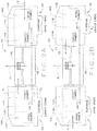
- FIGS. 2A and 2B illustrate this alternating sequence of operation in which FIG. 2A illustrates a first half cycle of operation and FIG. 2B illustrates the second half cycle of operation.
- FIG. 2A during the first half cycle of operation the first compressor head 102 is in the exhaust stroke and exhausts a first gas flow A 1 , while the second compressor head 104 is in the intake stroke and simultaneously intakes a second gas flow B.
- FIG. 2B during the second half cycle of operation the first compressor head 102 is in the intake stroke and intakes gas flow A, while the second compressor head 104 is in the exhaust stroke and simultaneously exhausts gas flow B 1 .
- An output connector 106 is in fluid flow communication with the first compressor head 102 and the second compressor head 104 for permitting a continuous alternating exhaust of a portion of gas flow A or B , designated A 1 or B 1 , generated by the first compressor head 102 or the second compressor head 104, respectively.
- the compressor apparatus 100 includes a shuttling by-pass component 108 that is in fluid flow communication with the first compressor head 102 and the second compressor head 104 for permitting alternating gas flow directly between the first compressor head 102 and the second compressor head 104 during their respective exhaust strokes such that the a portion of the first gas flow A , designated A 2 , is diverted from the first compressor head 102 directly to the second compressor head 104, while a portion of the second gas flow B , designated B 2 , is then diverted from the second compressor head 104 to the first compressor head 102 during the alternating exhaust strokes of the compressor apparatus 100.
- a shuttling by-pass component 108 that is in fluid flow communication with the first compressor head 102 and the second compressor head 104 for permitting alternating gas flow directly between the first compressor head 102 and the second compressor head 104 during their respective exhaust strokes such that the a portion of the first gas flow A , designated A 2 , is diverted from the first compressor head 102 directly to the second compressor head 104, while a portion of the second
- the first half cycle of operation for the compressor apparatus 100 requires that diverted gas flow A 2 from the first compressor head 102 flow into the second compressor head 104 through the shuttling by-pass component 108 in one direction, which completes the first half cycle of operation, and then diverted gas flow B 2 from the second compressor head 104 may flow into the first compressor head 102 in an opposite direction through the shuttling by-pass component 108 during the second half cycle of operation in a continuous alternating sequence of diverted gas flow A 2 and B 2 .
- the flow of diverted gas flows A 2 and B 2 between the first compressor head 102 and the second compressor head 104 follows the same alternating sequence of operation.
- diverted gas flow A 2 is directed from the first compressor head 102 into the second compressor head 104 as the gas flow A 1 exits the output connector 106, while gas flow B simultaneously enters the second compressor head 104.
- the diverted gas flow B 2 now flows from the second compressor head 104 into the first compressor head 102 as the gas flow B 1 exits the output connector 106, while gas flow A simultaneously enters the first compressor head 102.
- the compressor apparatus 100 has been shown to achieve minimum steady flow rates as low as 0.2 liters per minute, which is far below flow rates that are normally achieved by the conventional compressor apparatuses 10 without the by-pass component 108 for diverting a portion of gas flow from one compressor head 102 or 104 to the other compressor head 102 or 104.
- comparison tests have been conducted that show that the flow rate ratio of a maximum flow rate to a minimum flow rate is less than 100 to 1 for conventional compressor apparatuses, while a similar test conducted on the compressor apparatus 100 with the shuttling by-pass component 108 have shown a flow rate ratio of 480 to 1 can be achieved.
- the compressor apparatus 100 can switch the shuttling by-pass component 108 between operational and non-operational states such that an extremely low flow rate can be achieved when the shuttling by-pass component 108 is made operational, while an extremely high flow rate can be achieved when the shuttling by-pass component 108 is made non-operational by the compressor apparatus 100.
- a flow rate ratio of over 800 to 1 has been achieved.
- one embodiment of the compressor apparatus 100 may include the first compressor head 102 and the second compressor head 104 in fluid flow communication with an intake connector 106A for allowing the entry of gas flows A or B during the respective intake strokes and an output connector 106B gas flows A 1 or B 1 during the respective exhaust strokes for delivery to a patient through a ventilator (not shown).
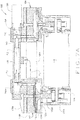
- FIG. 7A and 7B illustrate the various flow pathways through the compressor apparatus 100 in which the first compressor head 102 and the second compressor head 104 operate in alternating intake and exhaust strokes during completion of a full cycle of operation. In the first half cycle of operation undertaken by the compressor apparatus 100 shown in FIG.
- the first compressor head 102 draws in gas flow A into the first compressor head 102 during its respective intake stroke, while the second compressor head 104 simultaneously exhausts out gas flow B 1 through the output connector 107 and diverts a portion of gas flow B 1 , designated gas flow B 2 , through the shuttling by-pass component 108 to the first compressor head 102 during its respective exhaust stroke.
- the second compressor head 104 simultaneously exhausts out gas flow B 1 through the output connector 107 and diverts a portion of gas flow B 1 , designated gas flow B 2 , through the shuttling by-pass component 108 to the first compressor head 102 during its respective exhaust stroke.
- the first compressor head 102 exhausts out gas flow A through the output connector 106 during its respective exhaust stroke while simultaneously diverting a portion of gas flow A 1 , designated gas flow A 2 , through the shuttling by-pass component 108 in a direction opposite to that taken by the diverted gas flow B 2 to the second compressor head 104 as the second compressor head 104 simultaneously draws in gas flow B during its respective intake stroke.
- the compressor apparatus 100 completes a full cycle of operation when the first compressor head 102 and second compressor head 104 have alternately drawn in respective gas flows A or B and then forced out respective gas flows A 1 , A 2 or B 1 , B 2 in alternating fashion through the shuttling by-pass component 108 or the output connector 107 to complete an intake stroke and an exhaust stroke, respectively.
- the first compressor head 102 is substantially similar in structure and operation as the second compressor head 104 with the exception that the first compressor head 102 operates in alternating sequence relative to the second compressor head 104 to complete a full cycle of operation for the compressor apparatus 100.
- a motor 116 is provided to operate the first compressor head 102 and the second compressor head 104.
- the motor 116 includes a first rotatable shaft 144 for operating the first compressor head 102 and a second rotatable shaft 146 for operating the second compressor head 104.
- the first compressor head 102 includes a pump casing 124A defining a chamber 134A having an arrangement of a connecting rod 128A engaged to an eccentric mass 130A and counterweight 132A disposed therein.
- the bottom portion of the connecting rod 128A is engaged to the eccentric mass 130A and counterweight 132A, while the top portion of the connecting rod 128A is engaged to a flexible diaphragm 126A through a set screw 162A.
- the bottom portion of the connecting rod 128A is engaged to the rotatable shaft 144 of the motor 116 for moving the connecting rod 128A in an eccentric motion.
- the eccentric movement of the connecting rod 128A by the motor 116 moves the diaphragm 126A in a reciprocating motion.
- An adaptor plate 136A may engage one end of the motor 116 to the pump casing 124A.
- the top portion of the pump casing 124 is engaged to the bottom portion of a compressor head housing 118A, while the top head of the compressor head housing 118A is engaged to a cover head 138A.
- the compressor head housing 118A includes an inlet 140A that communicates with the intake chamber 110A for permitting the gas flow A to enter therein.
- the intake chamber 110A is in fluid flow communication with the cavity 112A through a plurality of one-way intake valves 120A that permit the inflow of gas into the cavity 112A from the intake chamber 110A, but prevents retrograde gas flow back into the intake chamber 110A.
- the cavity 112A is in fluid flow communication with the exhaust chamber 122A through a plurality of one-way exhaust valves 122A that permit the inflow of gas into the exhaust chamber 114A from the cavity 112A, but prevents retrograde gas flow back into the cavity 112A.
- the cavity 112A is configured to act in concert with the reciprocating diaphragm 126A such that movement of the diaphragm 126A from the cavity 112A during one-half cycle causes gas flow into the cavity 112A from the intake chamber 110A, while movement of the diaphragm 126A toward the cavity 112A during the other half-cycle causes the gas to become compressed and flow from the cavity 112A and into the exhaust chamber 114A such that the compressed gas exits the outlet connector 107 through the outlet 142A of the compressor head housing 118A.
- the second compressor head 104 includes a pump casing 124B defining a chamber 134B having an arrangement of a connecting rod 128B engaged to an eccentric mass 130B and counterweight 132B disposed therein.
- the bottom portion of the connecting rod 128B is engaged to the eccentric mass 130B and counterweight 132B, while the top portion of the connecting rod 128B is engaged to a flexible diaphragm 126B through a set screw 162B.
- the bottom portion of the connecting rod 128B is engaged to the rotatable shaft 144 of the motor 116 for moving the connecting rod 128B in an eccentric motion.
- the eccentric movement of the connecting rod 128B by the motor 116 moves the diaphragm 126B in a reciprocating motion.
- An adaptor plate 136B may engage one end of the motor 116 to the pump casing 124B.
- the top portion of the pump casing 124 is engaged to the bottom portion of a compressor head housing 118B, while the top head of the compressor head housing 118B is engaged to a cover head 138A.
- the compressor head housing 118B includes an inlet 140B that communicates with the intake chamber 110B for permitting the gas flow B to enter therein.
- the intake chamber 110B is in fluid flow communication with the cavity 112B through a plurality of one-way intake valves 120B that permit the inflow of gas into the cavity 112B from the intake chamber 110B, but prevents retrograde gas flow back into the intake chamber 110B.
- the cavity 112B is in fluid flow communication with the exhaust chamber 122B through a plurality of one-way exhaust valves 122B that permit the inflow of gas into the exhaust chamber 114B from the cavity 112B, but prevents retrograde gas flow back into the cavity 112B.
- the cavity 112B is configured to act in concert with the reciprocating diaphragm 126B such that movement of the diaphragm 126B from the cavity 112B during first half cycle causes gas flow into the cavity 112B from the intake chamber 110B, while movement of the diaphragm 126B toward the cavity 112B during the second half cycle causes the gas to become compressed and flow from the cavity 112B and into the exhaust chamber 114B such that the compressed gas exits the outlet connector 106B through the outlet 142B of the compressor head housing 118B.
- the shuttling by-pass component 108 may be an elongated hollow shaft that permits two-way gas flow between the first compressor head 102 and the second compressor head 104 when diverted gas flow A 2 and diverted gas flow B 2 alternately flow between the compressor heads 102 and 104.
- the shuttling by-pass component 108 defines one end that engages a by-pass fitting 148A for coupling the shuttling by-pass component 108 to the cover head 138A of the first compressor head 102 and an opposite end that engages another by-pass fitting 148B for coupling the shuttling by-pass component 108 to the second compressor head 104.
- Sealing elements 158A such as O-rings, provide a fluid-tight seal between the cover head 138A and the by-pass fitting 148A, while sealing elements 158B provide a fluid-tight seal between the cover head 138B and the by-pass fitting 148B.
- the by-pass fitting 148B is operatively engaged to a solenoid 150 through a by-pass seat 152 having a spring 154.
- the spring 154 applies a bias for permitting or preventing fluid flow communication through an orifice 149 formed by the cover head 138B, which is configured to engage the by-pass seat 152 by action of the solenoid 150 which opens and closes the orifice 149 to diverted gas flow A 2 or B 2 .
- the presence of the shuttling by-pass component 108 allows for the compressor apparatus 100 to achieve extremely lower and steadier flow rates in comparison to the flow rates achievable by the conventional compressor apparatus 10 without the by-pass component 108.
- the solenoid 150 opens the by-pass seat 152 during the exhaust stroke of the first compressor head 102 to permit diverted gas flow A 2 to flow from the first compressor head 102 to the second compressor head 104 during first half of cycle of operation.
- the solenoid 150 opens the by-pass seat 152 during the exhaust stroke of the second compressor head 104 to permit diverted gas flow B 2 to flow from the second compressor head 104 to the first compressor head 102 during the second half cycle of operation in order to complete a full cycle of operation by the compressor apparatus 100.
- the orifice size of the shuttling by-pass component 108 may be tailored to achieve a particular flow rate by the compressor apparatus 100 by diverting a specific amount of diverted gas flow from each of the first and second compressor heads 102 and 104.
- the shuttling by-pass component 108 may include a variable orifice (not shown) that provides a variable-sized opening for varying the degree of diverted gas flow A 2 or B 2 permitted to flow through the shuttling by-pass component 108 to the other compressor head 102 or 104 in order to provide flow adjustment capability. In this manner, the amount of diverted gas flow A 2 and B 2 may be adjusted for achieving different degrees of low flow rates by the compressor apparatus 100.
- the shuttling by-pass component 108 may be a screw drive or rotary actuator that may be used to open the orifice 149 as a substitute for the solenoid 150.
- the advantages of incorporating the shuttling by-pass component 108 into the compressor apparatus 100 is that it lowers the potential steady flow rate attainable by the compressor apparatus 100 by diverting a portion of the gas flow from one compressor head during its exhaust cycle to the other compressor head during its intake cycle, and vice versa, as one full cycle of operation of the compressor apparatus 100 is completed.
- the compressor apparatus 100 with the shuttling by-pass component 108 can achieve an extremely low flow rate, such as 0.1 liters per minute, when about 97% (based on an 80+ liters per minute of compressor apparatus 100 capacity) of the exhausted gas flow is diverted to the other compressor head and vice versa. This results in a maximum to minimum flow ratio of 800 to 1.
- the same bypass function may be applied to other compressors with varying capacity to achieve either higher or lower bypass flow rates.
- the shuttling by-pass component 108 may be incorporated into the compressor apparatus 100 having a motor with a fixed power source as an after market modification, which may be used as a means of achieving flow adjustment for the compressor apparatus by varying the amount of gas flow that may be diverted through the shuttling by-pass component 108.
- a compressor apparatus 100 having a first compressor head 102 in fluid flow communication with a second compressor head 104 through an output connector 106 and then engaging a shuttling by-pass component 108 in fluid flow communication between the first compressor head 102 and the second compressor head 104.
- the compressor apparatus 100 is engaged to a ventilator system for providing gas flow to the first compressor head 102 and the second compressor head 104.
- the compressor apparatus 100 is actuated such that the first compressor head 102 generates a first gas flow during a first exhaust stroke of the first compressor head 102 and the second compressor head 104 generates a second gas flow during an alternating second exhaust stroke of the second compressor head 104.
- a portion of the first gas flow is allowed to flow from the first compressor head 102 and into the second compressor head 104 through the shuttling by-pass component 108 during the first exhaust stroke of the first compressor head 102 and then allowing a portion of the alternating second gas flow from the second compressor head 104 to flow through the shuttling by-pass component 108 and into the first compressor head 102 during an alternating second exhaust stroke of the second compressor head 104.
- the first compressor head 102 is engaged to the second compressor head 104 through an output connector 106 to permit exhaust of a gas flow from the first compressor head 102 and the second compressor head 104 in alternating sequence.
- a shuttling by-pass component 108 is engaged between the first compressor head 102 and the second compressor head 104 for establishing fluid flow communication between the first compressor head 102 and the second compressor head 104 to permit a portion of the exhausted gas flow from either the first compressor head 102 or the second compressor head 104 to be diverted to the other respective compressor head 102 or 104. This allows the compressor apparatus 100 to achieve a much lower and steadier flow rate using less power than would otherwise be required by a compressor apparatus 10 without the shuttling by-pass component 108.
- a motor 116 is operatively engaged with the first compressor head 102 and the second compressor head 104 for driving the first compressor head 102 and the second compressor head 104 in alternating sequence.
- the compressor apparatus 100 with the shuttling by-pass component 108 may have applications outside the medical field described herein.
- the compressor apparatus 100 may be used in heating and air conditioning applications as well as refrigeration industries where multi-speed compressors are commonly used.
- the first test was directed to comparing minimum/maximum flow rate ratios exhibited by the standard compressor apparatuses 10 relative to the compressor apparatus 100 and the second test was directed to comparing the variance in flow rate between a standard compressor apparatus 10 and the compressor apparatus 100 with the shuttling by-pass component 108.
- tables 1-5 below provide test results that compare the maximum/minimum flow rate ratio achieved by the compressor apparatus 100 with the shuttling by-pass component 108 (Table 5) with the maximum/minimum flow rate ratios achieved by four prior art standard compressor apparatuses 10 without the shuttling by-pass component 108 (Tables 1-4 ).
- table 1 represents a standard compressor apparatus 10 without the shuttling by-pass component 108 manufactured under the product name GAST (TM) 15D, which exhibits a minimum flow rate of 0.2 liters per minute at a voltage setting of 2 volts and a maximum flow rate of 17.1 liters per minute at a voltage setting of 12 volts.
- TM product name
- Table 2 represents another standard compressor apparatus 10 without the shuttling by-pass component 108 manufactured under the product name T-Squared (TM) , which exhibits a minimum flow rate of 5.1 liters per minute at a voltage setting of 1 volt and a maximum flow rate of 82.3 liters per minute at a voltage setting of 12 volts.
- Table 3 represents another standard compressor apparatus 10 without the shuttling by-pass component 108 manufactured under the product name KNF (TM) , which exhibits a minimum flow rate of 31.1 liters per minute at a voltage setting of 1 volt and a maximum flow rate of 73.8 liters per minute at a voltage setting of 8 volts.
- Table 4 represents yet another standard compressor apparatus 10 without the shuttling by-pass component 108 manufactured under the product name Powerex (TM) , which exhibits a minimum flow rate of 1.3 liters per minute at a voltage setting of 1.7 volts.
- table 5 represents a compressor apparatus 100 with the shuttling by-pass component 108 manufactured by the Applicants, which exhibits a minimum flow rate of 0.1 liters per minute at a voltage setting of 1 volt and a maximum flow rate of 48.1 liters per minute at a voltage setting of 12 volts when the shuttling by-pass component 108 is made operational, while the compressor apparatus 100 exhibits a minimum flow rate of 3.1 liters per minute at a voltage setting of 1 volt and a maximum flow rate of 83.5 liters per minute when the shuttling by-pass component 108 is made non-operational.
- the compressor apparatus 100 with the shuttling by-pass component 108 can operate to make the shuttling by-pass component 108 operational at times to achieve any extremely low flow rate, while making the shuttling by-pass component 108 non-operational at times to achieve an extremely high flow rate.
- Table 6 shows the minimum flow rate, maximum flow rate, and the output flow ratios (maximum flow rate/minimum flow rate) for each of the aforementioned compressor apparatuses 10 without the shuttling by-pass component 108 in comparison with the compressor apparatus 100 having the shuttling by-pass component 108.
- the flow rate ratio of the compressor apparatus 100 with the shuttling by-pass component 108 is almost ten times the flow rate ratio of the closest standard compressor apparatus 10 without the shuttling by-pass component 108.
- the flow rate ratio of the GAST (TM) 15D compressor apparatus 10 without the shuttling by-pass component 108 of table 1 is 85.5 to 1
- the flow rate ratio of the T-Squared (TM) compressor apparatus 10 without the shuttling by-pass component 108 of table 2 is 16.1 to 1
- the flow rate ratio of the KNF (TM) compressor apparatus 10 without the shuttling by-pass component 108 of table 3 is 2.4 to 1
- the flow rate ratio of the Powerex (TM) compressor apparatus 10 without the shuttling by-pass component 108 of table 4 is 61.0 to 1.
- the flow rate ratio of the compressor apparatus 100 when the shuttling by-pass component 108 is made operational is 481 to 1, while an even higher flow rate ratio of 836 to 1 can be achieved when the compressor apparatus 100 switches the shuttling by-pass component 108 between operational mode to achieve a low flow rate of 0.1 liters per minute and the non-operational mode to achieve a high flow rate of 83.5 liters per minute as illustrated in FIG. 5 .
- the test results clearly show that the compressor apparatus 100 with the shuttling by-pass component 108 has a far greater ratio of maximum flow rate to the minimum flow rate, thereby exhibiting much greater range of flow rates than is achievable by the prior art standard compressor apparatuses 10 without the by-pass component 108 under similar operating conditions.
- Table 7 shows the results of the second test for comparing the variance in flow rate, referred to as pulsations, for a standard compressor apparatus 10 as compared with the compressor apparatus 100 having the shuttling by-pass component 108 at the same flow rate of 10 liters per minute. Minimizing the flow rate pulsations or the variance in flow rate by the compressor apparatus when maintaining a particular flow rate is important since a large variance in flow rate can be felt by a patient connected to a ventilator when the compressor apparatus exhibits a high variance in flow rate when maintaining a particular flow rate.
- the standard compressor apparatus 10 without the shuttling by-pass components 108 exhibits a variance in flow rate about 2.5 times larger than the variance in flow rate for the compressor apparatus 100 with the shuttling by-pass component 108.
- Table 7 showing the test data illustrated in the graph of FIG. 9 is set forth below.
Landscapes
- Engineering & Computer Science (AREA)
- Mechanical Engineering (AREA)
- General Engineering & Computer Science (AREA)
- Compressor (AREA)
- Control Of Positive-Displacement Pumps (AREA)
- Structures Of Non-Positive Displacement Pumps (AREA)
- Compressors, Vaccum Pumps And Other Relevant Systems (AREA)
Description
- This document relates to a compressor apparatus for providing compressed gas, and in particular to a shuttling by-pass compressor apparatus used with a ventilator system to achieve steady flow rates using less power.
- In medicine, mechanical ventilation is a method to mechanically assist or replace spontaneous breathing of a patient using a machine called a ventilator. The ventilator may include a prior art compressor apparatus that draws in gas and delivers compressed gas to the patient in a controlled manner to meet patient specifications. As shown in
FIG. 1 , the priorart compressor apparatus 10 may include a pair ofcompressor heads art compressor apparatus 10. In the illustrated embodiment, each of thecompressor heads respective intake chamber respective inlet port respective cavity respective intake chamber cavity compressor head exhaust chamber 20A and 20B through a one-way exhaust valve (not shown), which then allows the compressed gas to exit thecompressor heads output connector 24. Although the prior art high flow compressor apparatus has proven satisfactory for its intended purpose, such a compressor apparatus is unable to provide both a steady flow of a small volume of gas at lower flow rates while also being capable of providing a steady flow of a large volume of gas at higher flow rates. Typically, the priorart compressor apparatus 10 cannot achieve steady state flow of gas at flow rates under 3 liters per minute or thecompressor apparatus 10 can stall since thecompressor apparatus 10 cannot achieve sufficiently low revolutions per minute by a standard motor used normally forcompressor apparatuses 10 that drives eachcompressor head -
FR2733688 - In one embodiment, a compressor apparatus may include a first compressor head for generating a first gas flow, a second compressor head in fluid flow communication with the first compressor head for generating a second gas flow, and an output connector in fluid flow communication with the first compressor head and the second compressor head for permitting a continuous alternating output of gas flow by the first compressor head and the second compressor head. The compressor apparatus may also include a shuttling by-pass component in fluid flow communication with the first compressor head and the second compressor head for permitting alternating gas flow between the first compressor head and the second compressor head such that a portion of the first gas flow is diverted from the first compressor head to the second compressor head and a portion of the second gas flow is diverted from the second compressor head to the first compressor head in an alternating sequence.
- In another embodiment, a method for using a compressor apparatus may include:
- providing a compressor apparatus including:
- a first compressor head for generating a first gas flow;
- a second compressor head in fluid flow communication with the second compressor head for generating a second gas flow;
- an output connector in fluid flow communication with the first compressor head and the second compressor head for permitting a continuous alternating output of gas flow by the first compressor head and the second compressor head; and
- a shuttling by-pass component in fluid flow communication with the first compressor head and the second compressor head for permitting alternating gas flow between the first compressor head and the second compressor head through such that a portion of the first gas flow is diverted from the first compressor head to the second compressor head and a portion of the second gas flow is diverted from the second compressor head to the first compressor head in alternating sequence;
- diverting a portion of the first gas flow from the first compressor head to the second compressor head through the shuttling by-pass component; and
- diverting a portion of the second gas flow from the second compressor head to the first compressor head through the shuttling by-pass component.
- In yet another embodiment, a method of manufacturing a compressor apparatus may include:
- engaging a first compressor head to a second compressor head with an output connector to permit an output of a first gas flow from the first compressor head and an output of a second gas flow from the second compressor head in an alternating sequence;
- engaging a shuttling by-pass component between the first compressor head and the second compressor head for establishing fluid flow communication between the first compressor head and the second compressor head to permit a portion of the outputted first gas to flow from the first compressor head to the second compressor head and a portion of the outputted second gas flow to flow from the second compressor head to the first compressor head in alternating sequence; and
- operatively engaging a motor with the first compressor head and the second compressor head for driving the first compressor head and the second compressor head in alternating sequence.
- Additional objectives, advantages and novel features will be set forth in the description which follows or will become apparent to those skilled in the art upon examination of the drawings and detailed description which follows.
-
-
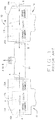
FIG. 1 is a simplified illustration of a prior art compressor head; -
FIG. 2A is a simplified illustration of one embodiment of a compressor apparatus having a shuttling by-pass component illustrating the flow of gas during half of the cycle of operation of the compressor apparatus; -
FIG. 2B is a simplified illustration of the compressor apparatus having the shuttling by-pass component illustrating the flow of gas during the other half of the cycle of operation of the compressor apparatus; -
FIG. 3 is an elevated perspective view of the compressor apparatus; -
FIG. 4 is a front view of the compressor apparatus; -
FIG. 5 is a top view of the compressor apparatus; -
FIG. 6 is a side view of the compressor apparatus; -
FIGS. 7A and7B are cross-sectional views taken along line 7-7 ofFIG. 6 illustrating the shuttling gas flow between a first compressor head and a second compressor head during different portions of the cycle for the compressor apparatus; -
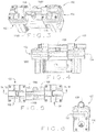
FIG. 8 is an exploded view of the compressor apparatus; -
FIG. 9 is a graph illustrating relative performance of the prior art compressor apparatus with the compressor apparatus having the shuttling by-pass component. - Corresponding reference characters indicate corresponding elements among the view of the drawings. The headings used in the figures should not be interpreted to limit the scope of the claims.
- As described herein, various embodiments of a compressor apparatus having a shuttling by-pass component is configured such that a portion of each gas flow generated by one compressor head is diverted to the other compressor head, and vice versa, through a shuttle component to achieve an efficient steady output of gas at extremely low flow rates. The result is a minimum to maximum flow ratio that is much greater than standard compressor apparatuses.
- Referring to the drawings, various embodiments of the compressor apparatus are illustrated and generally indicated as 100 in
FIGS. 2-8 . In one embodiment, thecompressor apparatus 100 includes afirst compressor head 102 and asecond compressor head 104 that operate in alternating sequence of intake strokes, wherein gas is drawn into either thefirst compressor head 102 orsecond compressor head 104 and alternating sequence of exhaust strokes, wherein gas is exhausted from either thefirst compressor head 102 orsecond compressor head 104 in which first and second half cycles of operation represent one full cycle of operation of thecompressor apparatus 100. For example, in the first half cycle of operation thefirst compressor head 102 is in the intake stroke, while thesecond compressor head 104 is in the exhaust stroke. In the second half cycle of operation thefirst compressor head 102 is in the exhaust stroke, while thesecond compressor head 104 is in the intake stroke. -
FIGS. 2A and 2B illustrate this alternating sequence of operation in whichFIG. 2A illustrates a first half cycle of operation andFIG. 2B illustrates the second half cycle of operation. As shown inFIG. 2A , during the first half cycle of operation thefirst compressor head 102 is in the exhaust stroke and exhausts a first gas flow A1, while thesecond compressor head 104 is in the intake stroke and simultaneously intakes a second gas flow B. Conversely, as shown inFIG. 2B , during the second half cycle of operation thefirst compressor head 102 is in the intake stroke and intakes gas flow A, while thesecond compressor head 104 is in the exhaust stroke and simultaneously exhausts gas flow B1. Anoutput connector 106 is in fluid flow communication with thefirst compressor head 102 and thesecond compressor head 104 for permitting a continuous alternating exhaust of a portion of gas flow A or B, designated A1 or B1, generated by thefirst compressor head 102 or thesecond compressor head 104, respectively. In addition, thecompressor apparatus 100 includes a shuttling by-pass component 108 that is in fluid flow communication with thefirst compressor head 102 and thesecond compressor head 104 for permitting alternating gas flow directly between thefirst compressor head 102 and thesecond compressor head 104 during their respective exhaust strokes such that the a portion of the first gas flow A, designated A2, is diverted from thefirst compressor head 102 directly to thesecond compressor head 104, while a portion of the second gas flow B, designated B2, is then diverted from thesecond compressor head 104 to thefirst compressor head 102 during the alternating exhaust strokes of thecompressor apparatus 100. In one embodiment, the first half cycle of operation for thecompressor apparatus 100 requires that diverted gas flow A2 from thefirst compressor head 102 flow into thesecond compressor head 104 through the shuttling by-pass component 108 in one direction, which completes the first half cycle of operation, and then diverted gas flow B2 from thesecond compressor head 104 may flow into thefirst compressor head 102 in an opposite direction through the shuttling by-pass component 108 during the second half cycle of operation in a continuous alternating sequence of diverted gas flow A2 and B2. Since thefirst compressor head 102 and thesecond compressor head 104 exhaust gas flows A1 or B1 from thecompressor apparatus 100 in a continuous alternating sequence, the flow of diverted gas flows A2 and B2 between thefirst compressor head 102 and thesecond compressor head 104 follows the same alternating sequence of operation. For example, during the first half cycle of operation diverted gas flow A2 is directed from thefirst compressor head 102 into thesecond compressor head 104 as the gas flow A1 exits theoutput connector 106, while gas flow B simultaneously enters thesecond compressor head 104. Conversely, during the second half cycle of operation the diverted gas flow B2 now flows from thesecond compressor head 104 into thefirst compressor head 102 as the gas flow B1 exits theoutput connector 106, while gas flow A simultaneously enters thefirst compressor head 102. For example, thecompressor apparatus 100 has been shown to achieve minimum steady flow rates as low as 0.2 liters per minute, which is far below flow rates that are normally achieved by theconventional compressor apparatuses 10 without the by-pass component 108 for diverting a portion of gas flow from onecompressor head other compressor head compressor apparatus 100 with the shuttling by-pass component 108 have shown a flow rate ratio of 480 to 1 can be achieved. Moreover, in some embodiments, thecompressor apparatus 100 can switch the shuttling by-pass component 108 between operational and non-operational states such that an extremely low flow rate can be achieved when the shuttling by-pass component 108 is made operational, while an extremely high flow rate can be achieved when the shuttling by-pass component 108 is made non-operational by thecompressor apparatus 100. In such embodiments of thecompressor apparatus 100, a flow rate ratio of over 800 to 1 has been achieved. - Referring to
FIGS. 3-6 , one embodiment of thecompressor apparatus 100 may include thefirst compressor head 102 and thesecond compressor head 104 in fluid flow communication with anintake connector 106A for allowing the entry of gas flows A or B during the respective intake strokes and anoutput connector 106B gas flows A1 or B1 during the respective exhaust strokes for delivery to a patient through a ventilator (not shown).FIG. 7A and7B , illustrate the various flow pathways through thecompressor apparatus 100 in which thefirst compressor head 102 and thesecond compressor head 104 operate in alternating intake and exhaust strokes during completion of a full cycle of operation. In the first half cycle of operation undertaken by thecompressor apparatus 100 shown inFIG. 7A , thefirst compressor head 102 draws in gas flow A into thefirst compressor head 102 during its respective intake stroke, while thesecond compressor head 104 simultaneously exhausts out gas flow B1 through theoutput connector 107 and diverts a portion of gas flow B1, designated gas flow B2, through the shuttling by-pass component 108 to thefirst compressor head 102 during its respective exhaust stroke. Conversely, during the second half cycle of operation by thecompressor apparatus 100 shown inFIG. 7B , thefirst compressor head 102 exhausts out gas flow A through theoutput connector 106 during its respective exhaust stroke while simultaneously diverting a portion of gas flow A1, designated gas flow A2, through the shuttling by-pass component 108 in a direction opposite to that taken by the diverted gas flow B2 to thesecond compressor head 104 as thesecond compressor head 104 simultaneously draws in gas flow B during its respective intake stroke. As such, thecompressor apparatus 100 completes a full cycle of operation when thefirst compressor head 102 andsecond compressor head 104 have alternately drawn in respective gas flows A or B and then forced out respective gas flows A1, A2 or B1, B2 in alternating fashion through the shuttling by-pass component 108 or theoutput connector 107 to complete an intake stroke and an exhaust stroke, respectively. - Referring to
FIG. 8 , the structural elements of thecompressor apparatus 100 and their operation will be discussed in greater detail. In one embodiment, thefirst compressor head 102 is substantially similar in structure and operation as thesecond compressor head 104 with the exception that thefirst compressor head 102 operates in alternating sequence relative to thesecond compressor head 104 to complete a full cycle of operation for thecompressor apparatus 100. Amotor 116 is provided to operate thefirst compressor head 102 and thesecond compressor head 104. In particular, themotor 116 includes a firstrotatable shaft 144 for operating thefirst compressor head 102 and a secondrotatable shaft 146 for operating thesecond compressor head 104. - As shown, the
first compressor head 102 includes apump casing 124A defining achamber 134A having an arrangement of a connectingrod 128A engaged to aneccentric mass 130A andcounterweight 132A disposed therein. The bottom portion of the connectingrod 128A is engaged to theeccentric mass 130A andcounterweight 132A, while the top portion of the connectingrod 128A is engaged to aflexible diaphragm 126A through aset screw 162A. Moreover, the bottom portion of the connectingrod 128A is engaged to therotatable shaft 144 of themotor 116 for moving the connectingrod 128A in an eccentric motion. In operation, the eccentric movement of the connectingrod 128A by themotor 116 moves thediaphragm 126A in a reciprocating motion. Anadaptor plate 136A may engage one end of themotor 116 to thepump casing 124A. - In one embodiment, the top portion of the pump casing 124 is engaged to the bottom portion of a
compressor head housing 118A, while the top head of thecompressor head housing 118A is engaged to acover head 138A. Thecompressor head housing 118A includes aninlet 140A that communicates with theintake chamber 110A for permitting the gas flow A to enter therein. Theintake chamber 110A is in fluid flow communication with thecavity 112A through a plurality of one-way intake valves 120A that permit the inflow of gas into thecavity 112A from theintake chamber 110A, but prevents retrograde gas flow back into theintake chamber 110A. In addition, thecavity 112A is in fluid flow communication with theexhaust chamber 122A through a plurality of one-way exhaust valves 122A that permit the inflow of gas into theexhaust chamber 114A from thecavity 112A, but prevents retrograde gas flow back into thecavity 112A. Thecavity 112A is configured to act in concert with thereciprocating diaphragm 126A such that movement of thediaphragm 126A from thecavity 112A during one-half cycle causes gas flow into thecavity 112A from theintake chamber 110A, while movement of thediaphragm 126A toward thecavity 112A during the other half-cycle causes the gas to become compressed and flow from thecavity 112A and into theexhaust chamber 114A such that the compressed gas exits theoutlet connector 107 through theoutlet 142A of thecompressor head housing 118A. - Similar to the
first compressor head 102, thesecond compressor head 104 includes apump casing 124B defining a chamber 134B having an arrangement of a connectingrod 128B engaged to aneccentric mass 130B andcounterweight 132B disposed therein. The bottom portion of the connectingrod 128B is engaged to theeccentric mass 130B andcounterweight 132B, while the top portion of the connectingrod 128B is engaged to aflexible diaphragm 126B through aset screw 162B. Moreover, the bottom portion of the connectingrod 128B is engaged to therotatable shaft 144 of themotor 116 for moving the connectingrod 128B in an eccentric motion. In operation, the eccentric movement of the connectingrod 128B by themotor 116 moves thediaphragm 126B in a reciprocating motion. An adaptor plate 136B may engage one end of themotor 116 to thepump casing 124B. - In one embodiment, the top portion of the pump casing 124 is engaged to the bottom portion of a
compressor head housing 118B, while the top head of thecompressor head housing 118B is engaged to acover head 138A. Thecompressor head housing 118B includes aninlet 140B that communicates with theintake chamber 110B for permitting the gas flow B to enter therein. Theintake chamber 110B is in fluid flow communication with thecavity 112B through a plurality of one-way intake valves 120B that permit the inflow of gas into thecavity 112B from theintake chamber 110B, but prevents retrograde gas flow back into theintake chamber 110B. In addition, thecavity 112B is in fluid flow communication with theexhaust chamber 122B through a plurality of one-way exhaust valves 122B that permit the inflow of gas into theexhaust chamber 114B from thecavity 112B, but prevents retrograde gas flow back into thecavity 112B. Thecavity 112B is configured to act in concert with thereciprocating diaphragm 126B such that movement of thediaphragm 126B from thecavity 112B during first half cycle causes gas flow into thecavity 112B from theintake chamber 110B, while movement of thediaphragm 126B toward thecavity 112B during the second half cycle causes the gas to become compressed and flow from thecavity 112B and into theexhaust chamber 114B such that the compressed gas exits theoutlet connector 106B through theoutlet 142B of thecompressor head housing 118B. - As further shown, the shuttling by-
pass component 108 may be an elongated hollow shaft that permits two-way gas flow between thefirst compressor head 102 and thesecond compressor head 104 when diverted gas flow A2 and diverted gas flow B2 alternately flow between the compressor heads 102 and 104. The shuttling by-pass component 108 defines one end that engages a by-pass fitting 148A for coupling the shuttling by-pass component 108 to thecover head 138A of thefirst compressor head 102 and an opposite end that engages another by-pass fitting 148B for coupling the shuttling by-pass component 108 to thesecond compressor head 104.Sealing elements 158A, such as O-rings, provide a fluid-tight seal between thecover head 138A and the by-pass fitting 148A, while sealingelements 158B provide a fluid-tight seal between thecover head 138B and the by-pass fitting 148B. In one embodiment, the by-pass fitting 148B is operatively engaged to asolenoid 150 through a by-pass seat 152 having aspring 154. Thespring 154 applies a bias for permitting or preventing fluid flow communication through anorifice 149 formed by thecover head 138B, which is configured to engage the by-pass seat 152 by action of thesolenoid 150 which opens and closes theorifice 149 to diverted gas flow A2 or B2. As such, the presence of the shuttling by-pass component 108 allows for thecompressor apparatus 100 to achieve extremely lower and steadier flow rates in comparison to the flow rates achievable by theconventional compressor apparatus 10 without the by-pass component 108. - In operation, the
solenoid 150 opens the by-pass seat 152 during the exhaust stroke of thefirst compressor head 102 to permit diverted gas flow A2 to flow from thefirst compressor head 102 to thesecond compressor head 104 during first half of cycle of operation. Similarly, thesolenoid 150 opens the by-pass seat 152 during the exhaust stroke of thesecond compressor head 104 to permit diverted gas flow B2 to flow from thesecond compressor head 104 to thefirst compressor head 102 during the second half cycle of operation in order to complete a full cycle of operation by thecompressor apparatus 100. In some components, the orifice size of the shuttling by-pass component 108 may be tailored to achieve a particular flow rate by thecompressor apparatus 100 by diverting a specific amount of diverted gas flow from each of the first and second compressor heads 102 and 104. In other embodiments, the shuttling by-pass component 108 may include a variable orifice (not shown) that provides a variable-sized opening for varying the degree of diverted gas flow A2 or B2 permitted to flow through the shuttling by-pass component 108 to theother compressor head compressor apparatus 100. - In some embodiments, the shuttling by-
pass component 108 may be a screw drive or rotary actuator that may be used to open theorifice 149 as a substitute for thesolenoid 150. - The advantages of incorporating the shuttling by-
pass component 108 into thecompressor apparatus 100 is that it lowers the potential steady flow rate attainable by thecompressor apparatus 100 by diverting a portion of the gas flow from one compressor head during its exhaust cycle to the other compressor head during its intake cycle, and vice versa, as one full cycle of operation of thecompressor apparatus 100 is completed. For example, thecompressor apparatus 100 with the shuttling by-pass component 108 can achieve an extremely low flow rate, such as 0.1 liters per minute, when about 97% (based on an 80+ liters per minute ofcompressor apparatus 100 capacity) of the exhausted gas flow is diverted to the other compressor head and vice versa. This results in a maximum to minimum flow ratio of 800 to 1. The same bypass function may be applied to other compressors with varying capacity to achieve either higher or lower bypass flow rates. - In some embodiments, the shuttling by-
pass component 108 may be incorporated into thecompressor apparatus 100 having a motor with a fixed power source as an after market modification, which may be used as a means of achieving flow adjustment for the compressor apparatus by varying the amount of gas flow that may be diverted through the shuttling by-pass component 108. - One method of using the
compressor apparatus 100 is described as follows. Acompressor apparatus 100 is provided having afirst compressor head 102 in fluid flow communication with asecond compressor head 104 through anoutput connector 106 and then engaging a shuttling by-pass component 108 in fluid flow communication between thefirst compressor head 102 and thesecond compressor head 104. Thecompressor apparatus 100 is engaged to a ventilator system for providing gas flow to thefirst compressor head 102 and thesecond compressor head 104. Thecompressor apparatus 100 is actuated such that thefirst compressor head 102 generates a first gas flow during a first exhaust stroke of thefirst compressor head 102 and thesecond compressor head 104 generates a second gas flow during an alternating second exhaust stroke of thesecond compressor head 104. A portion of the first gas flow is allowed to flow from thefirst compressor head 102 and into thesecond compressor head 104 through the shuttling by-pass component 108 during the first exhaust stroke of thefirst compressor head 102 and then allowing a portion of the alternating second gas flow from thesecond compressor head 104 to flow through the shuttling by-pass component 108 and into thefirst compressor head 102 during an alternating second exhaust stroke of thesecond compressor head 104. - One method of manufacturing the
compressor apparatus 100 is described as follows. Thefirst compressor head 102 is engaged to thesecond compressor head 104 through anoutput connector 106 to permit exhaust of a gas flow from thefirst compressor head 102 and thesecond compressor head 104 in alternating sequence. A shuttling by-pass component 108 is engaged between thefirst compressor head 102 and thesecond compressor head 104 for establishing fluid flow communication between thefirst compressor head 102 and thesecond compressor head 104 to permit a portion of the exhausted gas flow from either thefirst compressor head 102 or thesecond compressor head 104 to be diverted to the otherrespective compressor head compressor apparatus 100 to achieve a much lower and steadier flow rate using less power than would otherwise be required by acompressor apparatus 10 without the shuttling by-pass component 108. Amotor 116 is operatively engaged with thefirst compressor head 102 and thesecond compressor head 104 for driving thefirst compressor head 102 and thesecond compressor head 104 in alternating sequence. - The
compressor apparatus 100 with the shuttling by-pass component 108 may have applications outside the medical field described herein. For example, thecompressor apparatus 100 may be used in heating and air conditioning applications as well as refrigeration industries where multi-speed compressors are commonly used. - Two different tests were conducted to demonstrate the superior performance of the
compressor apparatus 100 with the shuttling by-pass component 108 in comparison with the prior artstandard compressor apparatuses 10 without the shuttling by-pass component 108. The first test was directed to comparing minimum/maximum flow rate ratios exhibited by thestandard compressor apparatuses 10 relative to thecompressor apparatus 100 and the second test was directed to comparing the variance in flow rate between astandard compressor apparatus 10 and thecompressor apparatus 100 with the shuttling by-pass component 108. With respect to the first test, tables 1-5 below provide test results that compare the maximum/minimum flow rate ratio achieved by thecompressor apparatus 100 with the shuttling by-pass component 108 (Table 5) with the maximum/minimum flow rate ratios achieved by four prior artstandard compressor apparatuses 10 without the shuttling by-pass component 108 (Tables 1-4). As shown, table 1 represents astandard compressor apparatus 10 without the shuttling by-pass component 108 manufactured under the product name GAST(TM) 15D, which exhibits a minimum flow rate of 0.2 liters per minute at a voltage setting of 2 volts and a maximum flow rate of 17.1 liters per minute at a voltage setting of 12 volts.
GAST(TM) 15D
PUMP WEIGHT: 1.54 LBS (0.70 Kg)TABLE 1 VDC LPM 0 0 1 0 2 0.2 3 0.4 4 1.7 5 4.4 6 6.7 7 8.5 8 10.8 9 12.5 10 13.7 11 15.6 12 17.1
PUMP WEIGHT: 3.82 LBS (1.73 Kg)TABLE 2 VDC LPM 0 0 1 5.1 2 11.3 3 18.4 4 25.9 5 32.5 6 39.6 7 46.6 8 53.8 9 60.9 10 68.2 11 75.1 12 82.3
PUMP WEIGHT: 6.64 LBS (3.01 Kg)TABLE 3 POT SETTING VDC LPM 0 0 1 31.1 2 58.7 3 69.6 4 72.7 5 73.8 6 73.8 7 73.8 8 73.8
ANEST IWATA PUMP WEIGHT: 2.74 LB (1.24 Kg)TABLE 4 VOLTAGE SETTING LPM 1.7 1.3 1.8 5.4 1.9 8.8 2 12.6 2.2 18.9 2.4 24.9 2.6 30.8 2.8 37.2 3 43.3 3.2 49.4 3.4 55.1 3.6 60.7 3.8 66.5 4 71.6 4.2 76.9 4.4 79.3 4.6 79.3
PUMP 1
WEIGHT: 4.44 LB (2.01 Kg)TABLE 5 VDC FULL FLOW LPM BYPASS FLOW LPM 1 3.1 0.1 2 10.3 0.3 3 17.7 0.8 4 22.4 5.1 5 33.8 10.6 6 40.7 13.6 7 45.8 18.7 8 55.4 24.1 9 63.1 31.2 10 69.3 37.1 11 76.4 43.2 12 83.5 48.1 - Table 2 represents another
standard compressor apparatus 10 without the shuttling by-pass component 108 manufactured under the product name T-Squared(TM), which exhibits a minimum flow rate of 5.1 liters per minute at a voltage setting of 1 volt and a maximum flow rate of 82.3 liters per minute at a voltage setting of 12 volts. Table 3 represents anotherstandard compressor apparatus 10 without the shuttling by-pass component 108 manufactured under the product name KNF(TM), which exhibits a minimum flow rate of 31.1 liters per minute at a voltage setting of 1 volt and a maximum flow rate of 73.8 liters per minute at a voltage setting of 8 volts. Table 4 represents yet anotherstandard compressor apparatus 10 without the shuttling by-pass component 108 manufactured under the product name Powerex(TM), which exhibits a minimum flow rate of 1.3 liters per minute at a voltage setting of 1.7 volts. Finally, table 5 represents acompressor apparatus 100 with the shuttling by-pass component 108 manufactured by the Applicants, which exhibits a minimum flow rate of 0.1 liters per minute at a voltage setting of 1 volt and a maximum flow rate of 48.1 liters per minute at a voltage setting of 12 volts when the shuttling by-pass component 108 is made operational, while thecompressor apparatus 100 exhibits a minimum flow rate of 3.1 liters per minute at a voltage setting of 1 volt and a maximum flow rate of 83.5 liters per minute when the shuttling by-pass component 108 is made non-operational. As noted above, thecompressor apparatus 100 with the shuttling by-pass component 108 can operate to make the shuttling by-pass component 108 operational at times to achieve any extremely low flow rate, while making the shuttling by-pass component 108 non-operational at times to achieve an extremely high flow rate. Table 6 shows the minimum flow rate, maximum flow rate, and the output flow ratios (maximum flow rate/minimum flow rate) for each of theaforementioned compressor apparatuses 10 without the shuttling by-pass component 108 in comparison with thecompressor apparatus 100 having the shuttling by-pass component 108.TABLE 6 GAST(™) 15D T SQUARED(™) KNF(™) POWEREX(™) ANEST IWATA ALLIED(™) Compressor Type Standard Standard Standard Standard By-Pass Minimum Flow 0.2 5.1 31.1 1.3 0.1 Maximum Flow 17.1 82.3 73.8 79.3 83.5 Output Flow Ratio (Max Flow / Min Flow) 85.5 16.1 2.4 61.0 835.0 - As shown in table 6, the flow rate ratio of the
compressor apparatus 100 with the shuttling by-pass component 108 is almost ten times the flow rate ratio of the closeststandard compressor apparatus 10 without the shuttling by-pass component 108. For example, the flow rate ratio of the GAST(TM)15D compressor apparatus 10 without the shuttling by-pass component 108 of table 1 is 85.5 to 1, the flow rate ratio of the T-Squared(TM) compressor apparatus 10 without the shuttling by-pass component 108 of table 2 is 16.1 to 1, the flow rate ratio of the KNF(TM) compressor apparatus 10 without the shuttling by-pass component 108 of table 3 is 2.4 to 1, and the flow rate ratio of the Powerex(TM) compressor apparatus 10 without the shuttling by-pass component 108 of table 4 is 61.0 to 1. In contrast, the flow rate ratio of thecompressor apparatus 100 when the shuttling by-pass component 108 is made operational is 481 to 1, while an even higher flow rate ratio of 836 to 1 can be achieved when thecompressor apparatus 100 switches the shuttling by-pass component 108 between operational mode to achieve a low flow rate of 0.1 liters per minute and the non-operational mode to achieve a high flow rate of 83.5 liters per minute as illustrated inFIG. 5 . The test results clearly show that thecompressor apparatus 100 with the shuttling by-pass component 108 has a far greater ratio of maximum flow rate to the minimum flow rate, thereby exhibiting much greater range of flow rates than is achievable by the prior artstandard compressor apparatuses 10 without the by-pass component 108 under similar operating conditions. It should be noted that although the voltage settings of the KNF(TM) and Powerex(TM) compressor apparatuses 10 are between 1-8 volts and 1.7-4.6 volts, respectively, rather than the normal voltage setting range of 1-12 volts used for theother compressor apparatuses 10 and thecompressor apparatus 100 during the tests, these smaller voltage setting ranges for the KNF(TM) and Powerex(TM) compressor apparatuses 10 are due to the smaller operational voltage settings for operating theseparticular compressor apparatuses 10 at the their equivalent full operational range to obtain both comparable minimum and maximum flow rates. - Table 7 shows the results of the second test for comparing the variance in flow rate, referred to as pulsations, for a
standard compressor apparatus 10 as compared with thecompressor apparatus 100 having the shuttling by-pass component 108 at the same flow rate of 10 liters per minute. Minimizing the flow rate pulsations or the variance in flow rate by the compressor apparatus when maintaining a particular flow rate is important since a large variance in flow rate can be felt by a patient connected to a ventilator when the compressor apparatus exhibits a high variance in flow rate when maintaining a particular flow rate. The graph illustrated inFIG. 9 and the test results between the two types ofcompressor apparatuses compressor apparatus 100 with the shuttling by-pass component 108 demonstrates a much lower variance in flow rate when maintaining a flow rate of 10 liters per minute than thestandard compressor apparatus 10 without the shuttling by-pass component 108 when maintaining the same 10 liters per minute flow rate. As shown, the flow rate variance in maintaining a flow rate of 10 liters per minute exhibited by thestandard compressor apparatus 10 without the shuttling by-pass component 108 is about 4.7 liters per minute, while the variance in maintaining the same 10 liters per minute flow rate exhibited by thecompressor apparatus 100 with the shuttling by-pass component 108 is about 2.0 liters per minute. As such, thestandard compressor apparatus 10 without the shuttling by-pass components 108 exhibits a variance in flow rate about 2.5 times larger than the variance in flow rate for thecompressor apparatus 100 with the shuttling by-pass component 108. Table 7 showing the test data illustrated in the graph ofFIG. 9 is set forth below.TABLE 7 Date--Time: Wed, Jun 15, 2011-- TIME Channel 1 LPM STP 1:58:43 PM TIME FLOW 0 10.15 0 9.65 0.0625 9.35 0.05 10.191 0.125 9.91 0.1 7.947 0.1875 9.91 0.15 8.368 0.25 9.88 0.2 8.225 0.3125 10.41 0.25 9.831 0.375 9.96 0.3 11.172 0.4375 9.96 0.35 11.377 0.5 9.26 0.4 10.701 0.5625 10.45 0.45 9.65 0.625 8.97 0.5 8.599 0.6875 8.97 0.55 8.008 0.75 10.25 0.6 8.853 0.8125 10.05 0.65 10.508 0.875 10.35 0.7 11.498 0.9375 10.35 0.75 11.969 1 9.64 0.8 11.728 1.0625 9.27 0.85 10.423 1.125 10.05 0.9 9.131 1.1875 10.05 0.95 8.756 1.25 8.91 1 9.892 1.3125 10.01 1.05 11.402 1.375 9.26 1.1 12.09 1.4375 9.26 1.15 11.981 1.5 9.9 1.2 11.426 1.5625 9.44 1.25 10.17 1.625 9.38 1.3 9.203 1.6875 9.38 1.35 8.865 1.75 9.54 1.4 9.928 1.8125 9.69 1.45 11.365 1.875 8.88 1.5 12.295 1.9375 8.88 1.55 12.549 2 10.25 1.6 11.788 2.0625 9.65 1.65 10.194 2.125 10.42 1.7 9.312 2.1875 10.42 1.75 9.264 2.25 9.7 1.8 10.459 2.3125 9.02 1.85 11.679 2.375 9.85 1.9 12.042 2.4375 9.85 1.95 11.873 2.5 8.95 2 11.003 2.5625 10.15 2.05 9.59 2.625 8.98 2.1 8.744 2.6875 8.98 2.15 8.95 2.75 9.73 2.2 10.266 2.8125 9.96 2.25 11.776 2.875 9.55 2.3 12.573 2.9375 9.55 2.35 12.368 3 9.17 2.4 11.317 3.0625 9.46 2.45 9.856 3.125 9.51 2.5 9.034 3.1875 9.51 2.55 9.517 3.25 10.2 2.6 10.943 3.3125 9.13 2.65 11.981 3.375 10.57 2.7 12.271 3.4375 10.57 2.75 11.679 3.5 9.94 2.8 10.363 3.5625 8.89 2.85 9.215 3.625 9.65 2.9 8.72 3.6875 9.65 2.95 9.602 3.75 8.94 3 11.172 3.8125 9.95 3.05 12.295 3.875 9.76 3.1 12.585 3.9375 9.76 3.15 12.078 4 9.66 3.2 10.749 4.0625 9.67 3.25 9.505 4.125 9.78 3.3 9.058 4.1875 9.78 3.35 10.085 4.25 9.18 3.4 11.522 4.3125 10.18 3.45 12.223 4.375 9.55 3.5 12.138 4.4375 10.27 3.55 11.595 4.5 10.27 3.6 10.218 4.5625 9.94 3.65 9.143 4.625 10.48 3.7 8.817 4.6875 9.84 3.75 10.013 4.75 9.84 3.8 11.462 4.8125 9.07 3.85 12.162 4.875 10.28 3.9 12.368 4.9375 8.88 3.95 11.522 5 8.88 4 10.109 5.0625 10.13 4.05 9.095 5.125 10 4.1 9.143 5.1875 10.36 4.15 10.484 5.25 10.36 4.2 11.583 5.3125 10.05 4.25 12.054 5.375 9.27 4.3 11.836 5.4375 9.78 4.35 11.184 5.5 9.78 4.4 10.013 5.5625 9.98 4.45 9.095 5.625 9.52 4.5 9.372 5.6875 10.12 4.55 10.846 5.75 10.12 4.6 12.078 5.8125 9.35 4.65 12.658 5.875 9.15 4.7 12.67 5.9375 9.64 4.75 11.365 6 9.64 4.8 9.976 6.0625 9.01 4.85 9.131 6.125 10.3 4.9 9.783 6.1875 8.6 4.95 11.232 6.25 8.6 5 12.199 6.3125 10.59 5.05 12.078 6.375 9.85 5.1 11.51 6.4375 10 5.15 10.363 6.5 10 5.2 9.348 6.5625 9.69 5.25 8.829 6.625 8.89 5.3 9.578 6.6875 9.8 5.35 11.027 6.75 9.8 5.4 12.283 6.8125 8.49 5.45 12.609 6.875 9.94 5.5 12.332 6.9375 8.97 5.55 11.075 7 8.97 5.6 9.638 7.0625 9.94 5.65 9.083 7.125 9.81 5.7 10.061 7.1875 9.65 5.75 11.438 7.25 9.65 5.8 12.078 7.3125 9.84 5.85 11.788 7.375 9.77 5.9 11.341 7.4375 9.32 5.95 10.278 7.5 9.81 6 9.191 7.5625 9.81 6.05 8.781 7.625 9.98 6.1 9.819 7.6875 9.44 6.15 11.184 7.75 9.64 6.2 12.271 7.8125 9.64 6.25 12.597 7.875 9.25 6.3 11.812 7.9375 9.44 6.35 10.206 8 9.03 6.4 9.119 8.0625 9.03 6.45 9.107 8.125 10.07 6.5 10.423 8.1875 9.93 6.55 11.426 8.25 10.29 6.6 11.909 8.3125 10.29 6.65 11.764 8.375 9.42 6.7 11.027 8.4375 8.84 6.75 9.735 8.5 10.07 6.8 8.913 8.5625 10.07 6.85 9.107 8.625 8.48 6.9 10.496 8.6875 10.15 6.95 11.836 8.75 9.34 7 12.15 8.8125 9.34 7.05 11.933 8.875 9.77 7.1 10.882 8.9375 9.84 7.15 9.662 9 9.7 7.2 8.926 9.0625 9.7 7.25 9.542 9.125 9.9 7.3 10.991 9.1875 9.71 7.35 12.066 9.25 9.34 7.4 12.102 9.3125 9.34 7.45 11.45 9.375 10.33 7.5 10.411 9.4375 9.52 7.55 9.312 9.5 10.49 7.6 8.684 9.5625 10.49 7.65 9.445 9.625 10.01 7.7 11.015 9.6875 8.48 7.75 12.15 9.75 9.96 7.8 12.259 9.8125 9.96 7.85 12.005 9.875 8.89 7.9 10.556 9.9375 10.3 7.95 9.312 10 8.83 8 8.865
Claims (15)
- A compressor apparatus (100) comprising:a first compressor head (102) for generating a first gas flow;a second compressor head (104) in fluid flow communication with the first compressor head (102) for generating a second gas flow;an output connector (106) in fluid flow communication with the first compressor head (102) and the second compressor head (104) for permitting a continuous alternating output of the first gas flow and the second gas flow by the first compressor head (102) and the second compressor head (104), respectively,characterized in that the compressor apparatus (100) further comprises:a shuttling by-pass component (108) in fluid flow communication with the first compressor head (102) and the second compressor head (104) for permitting alternating gas flow between the first compressor head (102) and the second compressor head (104) such that a portion of the first gas flow is diverted from the first compressor head (102) to the second compressor head (104) and a portion of the second gas flow is diverted from the second compressor head (104) to the first compressor head (102) in alternating sequence.
- The compressor apparatus (100) of claim 1, wherein the portion of the first gas flow diverted from the first compressor head (102) to the second compressor head (104), and vice versa, flows through the shuttling by-pass component (108) flows through a respective by-pass connector (148A, 148B) that is in fluid flow communication between the first compressor head (102) and the second compressor head (104).
- The compressor apparatus (100) of claim 2, wherein the portion of the second gas flow diverted from the second compressor head (104) to the first compressor head (102) through the by-pass component (148A, 148B) flows through the shuttling by-pass connector (108) that is in fluid flow communication between the first compressor head (102) and the second compressor head (104).
- The compressor apparatus (100) of claim 1, wherein the first compressor head (102) operates in a first intake stroke to draw in the first gas flow and an alternating first exhaust stroke to output the first gas flow while the second compressor head (104) operates in a second intake stroke to draw in the second gas flow and an alternating second exhaust stroke to output the second gas flow, wherein when the first compressor head (102) is in the first intake stroke the second compressor head (104) is simultaneously in the second exhaust stroke and wherein when the first compressor head (102) is in the first exhaust stroke the second compressor head (104) is simultaneously in the second intake stroke.
- The compressor apparatus (100) of claim 1, wherein the shuttling by-pass component (108) includes a by-pass orifice (149) for permitting the flow of either the diverted first gas flow or the diverted second gas flow when the by-pass orifice (149) is in the open position and preventing the flow of either the diverted first gas flow or the diverted second gas flow when the by-pass orifice is in the closed position.
- The compressor apparatus (100) of claim 5, wherein the by-pass orifice (149) is a solenoid (150) having a spring-loaded seat (152) that permits or prevents gas flow of either the diverted first gas flow or diverted second gas flow through the shuttling by-pass connector (108) by the by-pass orifice (149).
- The compressor apparatus (100) of claim 4, wherein the first compressor head (102) and the second compressor head (104) each comprise:an inlet port (140A, 140B) in fluid flow communication with an intake chamber (110A, 110B) for allowing the entry of the gas flow therein;at least one intake valve (120A, 120B) in communication with the intake chamber (110A, 110B) and a cavity (112A, 112B) for permitting the gas flow to flow from the intake chamber (110A, 110B) and into the cavity (112A, 112B) during a respective first and second intake strokes;at least one exhaust valve (122A, 122B) in communication with the cavity (112A, 112B) and an exhaust chamber (114A, 114B) for permitting the gas flow to flow from the cavity (112A, 1128) and into the exhaust chamber (114A, 114B) during a respective first and second exhaust strokes;a flexible diaphragm (126A, 126B) configured to be driven against the cavity (112A, 112B) in a reciprocating motion for drawing in the gas flow into the cavity (112A, 112B) in one motion of the flexible diaphragm (126A, 126B) during the respective first or second intake strokes and forcing gas out of the cavity (112A, 112B) in an opposite motion of the flexible diaphragm (126A, 126B) during the respective first or second exhaust strokes; andan outlet port (142A, 142B) in fluid flow communication with the exhaust chamber (114A, 114B) for permitting the gas flow to exit from the exhaust chamber (114A, 114B) during the respective first and second exhaust strokes.
- The compressor apparatus (100) of claim 4, wherein when the first compressor head (102) is in the exhaust stroke the portion of the first gas flow is diverted from the first compressor head (102) to the second compressor head (104) and wherein when the second compressor head (104) is in the exhaust stroke the portion of the second gas flow is diverted from the second compressor head (104) to the first compressor head (102).
- A method for using a compressor apparatus (100) comprising:providing a compressor apparatus (100) comprising:a first compressor head (102) for generating a first gas flow;a second compressor head (104) in fluid flow communication with the first compressor head (102) for generating a second gas flow;an output connector (106) in fluid flow communication with the first compressor head (102) and the second compressor head (104) for permitting a continuous alternating output of gas flow by the first compressor head (102) and the second compressor head (104); anda shuttling by-pass component (108) in fluid flow communication with the first compressor head (102) and the second compressor head (104) for permitting alternating gas flow between the first compressor head (102) and the second compressor head (104) through the shuttling by-pass component (108) such that a portion of the first gas flow is diverted from the first compressor head (102) to the second compressor head (104) and a portion of the second gas flow is diverted from the second compressor head (104) to the first compressor head (102) in alternating sequence;diverting a portion of the first gas flow from the first compressor head (102) to the second compressor head (104) through the shuttling by-pass component (108); anddiverting a portion of the second gas flow from the second compressor head (104) to the first compressor head (102) through the shuttling by-pass component (108) in alternating sequence with diverting the portion of the first gas flow from the first compressor head (102) to the second compressor head (104).
- The method of claim 9, wherein diverting the portion of the first gas flow from the first compressor head (102) to the second compressor head (104) alternates with diverting the portion of the second gas flow from the second compressor head (104) to the first compressor head (102).
- The method of claim 9, wherein diverting the portion of the first gas flow from the first compressor head (102) to the second compressor head (104) alternates with diverting the portion of the second gas flow from the second compressor head (104) to the first compressor head (102) allows for the operation of the compressor apparatus (100) at less than full potential capacity of both the first compressor head (102) and the second compressor head (104), respectively.
- A method of manufacturing a compressor apparatus (100) comprising:engaging a first compressor head (102) to a second compressor head (104) with an output connector (106) to permit an output of a first gas flow from the first compressor head (102) and an output of a second gas flow from the second compressor head (104) in an alternating sequence;engaging a shuttling by-pass component (108) between the first compressor head (102) and the second compressor head (104) for establishing fluid flow communication between the first compressor head (102) and the second compressor head (104) to permit a portion of the outputted first gas flow to flow from the first compressor head (102) to the second compressor head (104) and a portion of the outputted second gas flow to flow from the second compressor head (104) to the first compressor head (102) in alternating sequence; andoperatively engaging a motor (116) with the first compressor head (102) and the second compressor head (104) for driving the first compressor head (102) and the second compressor head (104) in alternating sequence.
- The method of claim 12, wherein the output connector (106) is a first output connector (106A) for outputting the first gas flow from the first compressor head (102) and a second output connector (106B) for outputting the second gas flow from the second compressor head (104).
- The method of claim 12, wherein the first compressor head (102) further comprises a first diaphragm (126A) for generating the first gas flow during an intake stroke of the first compressor head (102) and the second compressor head (104) further comprises a second diaphragm (126B) for generating the second gas flow during an intake stroke of the second compressor head (104), and wherein the first diaphragm (126A) causes a portion of the first gas flow to be diverted through the shuttling by-pass component (108) to the second compressor head (104) during an exhaust stroke of the first compressor head (102) and wherein the second diaphragm (126B) causes a portion of the second gas flow to be diverted through the shuttling by-pass (108) component to the first compressor head (102) during an exhaust stroke of the second compressor head (104).
- The method of claim 12, wherein the shuttling by-pass component (108) includes a by-pass orifice (149) for permitting the flow of either the diverted first gas flow or the diverted second gas flow through the shuttling by-pass component (108) when the by-pass orifice (149) is in the open position and preventing the flow of either the diverted first gas flow or the diverted second gas flow when the by-pass orifice (149) is in the closed position.
Applications Claiming Priority (2)
| Application Number | Priority Date | Filing Date | Title |
|---|---|---|---|
| US13/229,133 US9022746B2 (en) | 2011-09-09 | 2011-09-09 | Shuttling by-pass compressor apparatus |
| PCT/US2012/049715 WO2013036339A1 (en) | 2011-09-09 | 2012-08-06 | Shuttling by-pass compressor apparatus |
Publications (3)
| Publication Number | Publication Date |
|---|---|
| EP2753391A1 EP2753391A1 (en) | 2014-07-16 |
| EP2753391A4 EP2753391A4 (en) | 2015-07-29 |
| EP2753391B1 true EP2753391B1 (en) | 2016-12-28 |
Family
ID=47829991
Family Applications (1)
| Application Number | Title | Priority Date | Filing Date |
|---|---|---|---|
| EP12830772.5A Active EP2753391B1 (en) | 2011-09-09 | 2012-08-06 | Shuttling by-pass compressor apparatus |
Country Status (10)
| Country | Link |
|---|---|
| US (1) | US9022746B2 (en) |
| EP (1) | EP2753391B1 (en) |
| JP (1) | JP6055475B2 (en) |
| AU (1) | AU2012304846B2 (en) |
| BR (1) | BR112014005481B1 (en) |
| CA (1) | CA2846166C (en) |
| ES (1) | ES2617493T3 (en) |
| MX (1) | MX341725B (en) |
| RU (1) | RU2593360C2 (en) |
| WO (1) | WO2013036339A1 (en) |
Families Citing this family (5)
| Publication number | Priority date | Publication date | Assignee | Title |
|---|---|---|---|---|
| TWI683960B (en) * | 2017-09-15 | 2020-02-01 | 研能科技股份有限公司 | Gas transmitting device |
| US10920758B2 (en) * | 2018-06-29 | 2021-02-16 | Bendix Commercial Vehicle Systems Llc | Hypocycloid compressor |
| CA3200674A1 (en) | 2020-11-09 | 2022-05-12 | Pdc Machines Inc. | Hydraulically driven diaphragm compressor system |
| US11674508B2 (en) | 2021-11-08 | 2023-06-13 | Pdc Machines Inc. | High-throughput diaphragm compressor |
| US20250271931A1 (en) * | 2022-05-04 | 2025-08-28 | Hatpx, Inc. | Haptic glove system and manufacture of haptic glove systems |
Family Cites Families (22)
| Publication number | Priority date | Publication date | Assignee | Title |
|---|---|---|---|---|
| US2285215A (en) * | 1939-06-08 | 1942-06-02 | Binks Mfg Co | Fluid compressor |
| GB914343A (en) | 1959-02-06 | 1963-01-02 | Pye Ltd | Electronic time cycled respirator |
| US3101768A (en) * | 1960-09-15 | 1963-08-27 | Curtis Automotive Devices Inc | Resonant intermittent combustion devices |
| DE1453646A1 (en) * | 1964-05-22 | 1969-11-13 | Rau Swf Autozubehoer | Diaphragm pump with built-in electric motor |
| DE2158458A1 (en) * | 1971-11-25 | 1973-05-30 | Langen & Co | AUTOMATIC VENTING DEVICE |
| US4778356A (en) * | 1985-06-11 | 1988-10-18 | Hicks Cecil T | Diaphragm pump |
| US4842498A (en) * | 1987-01-20 | 1989-06-27 | Thomas Industries, Inc. | Diaphragm compressor |
| US4813979A (en) * | 1988-02-02 | 1989-03-21 | The United States Of America As Represented By The Secretary Of The Air Force | Secondary oxygen purifier for molecular sieve oxygen concentrator |
| DE3919667A1 (en) * | 1989-06-16 | 1990-12-20 | Schneider Druckluft Gmbh | Control system for double compressor unit - has arrangement to vary main load on alternate basis |
| DE9317083U1 (en) * | 1993-11-09 | 1994-01-13 | Knf-Neuberger Gmbh, 79112 Freiburg | Pump with a drive motor and a housing |
| FR2733688B1 (en) | 1995-05-05 | 1997-09-05 | Saime Sarl | BREATHING ASSISTANCE APPARATUS OF WHICH THE GAS FLOW SOURCE IS A MEMBRANE COMPRESSOR WITH ELECTROMAGNETIC ACTUATION |
| US6062256A (en) * | 1997-02-11 | 2000-05-16 | Engineering Measurements Company | Micro mass flow control apparatus and method |
| US6126410A (en) * | 1998-02-12 | 2000-10-03 | Gast Manufacturing Corporation | Head cover assembly for reciprocating compressor |
| US5968236A (en) * | 1998-02-20 | 1999-10-19 | Bassine; Stuart | Valve free oxygen concentrator |
| RU2146536C1 (en) * | 1999-04-16 | 2000-03-20 | Специальное конструкторское бюро экспериментального оборудования при Государственном научном центре Российской Федерации "Институт медико-биологических проблем" | Method for preparation and supply of therapeutic gas mix and device for its embodiment |
| US7320321B2 (en) | 2002-08-26 | 2008-01-22 | Automedx Inc. | Self-contained micromechanical ventilator |
| US7134849B1 (en) * | 2003-04-22 | 2006-11-14 | Trebor International, Inc. | Molded disposable pneumatic pump |
| JP2007525273A (en) * | 2004-02-26 | 2007-09-06 | セコス、 インコーポレイテッド | Self-contained micromechanical ventilator |
| US7517199B2 (en) * | 2004-11-17 | 2009-04-14 | Proportion Air Incorporated | Control system for an air operated diaphragm pump |
| US7686870B1 (en) | 2005-12-29 | 2010-03-30 | Inogen, Inc. | Expandable product rate portable gas fractionalization system |
| US8596992B2 (en) * | 2006-08-18 | 2013-12-03 | L•VAD Technology, Inc. | Air supply mechanism for ventricular assist system |
| US20090065007A1 (en) | 2007-09-06 | 2009-03-12 | Wilkinson William R | Oxygen concentrator apparatus and method |
-
2011
- 2011-09-09 US US13/229,133 patent/US9022746B2/en active Active
-
2012
- 2012-08-06 BR BR112014005481-9A patent/BR112014005481B1/en active IP Right Grant
- 2012-08-06 MX MX2014002678A patent/MX341725B/en active IP Right Grant
- 2012-08-06 EP EP12830772.5A patent/EP2753391B1/en active Active
- 2012-08-06 AU AU2012304846A patent/AU2012304846B2/en active Active
- 2012-08-06 CA CA2846166A patent/CA2846166C/en active Active
- 2012-08-06 ES ES12830772.5T patent/ES2617493T3/en active Active
- 2012-08-06 JP JP2014529720A patent/JP6055475B2/en active Active
- 2012-08-06 RU RU2014113758/14A patent/RU2593360C2/en active
- 2012-08-06 WO PCT/US2012/049715 patent/WO2013036339A1/en not_active Ceased
Also Published As
| Publication number | Publication date |
|---|---|
| JP2014526308A (en) | 2014-10-06 |
| RU2014113758A (en) | 2015-10-20 |
| EP2753391A4 (en) | 2015-07-29 |
| EP2753391A1 (en) | 2014-07-16 |
| RU2593360C2 (en) | 2016-08-10 |
| US9022746B2 (en) | 2015-05-05 |
| CA2846166A1 (en) | 2013-03-14 |
| AU2012304846A1 (en) | 2014-03-06 |
| BR112014005481B1 (en) | 2020-12-08 |
| CA2846166C (en) | 2019-06-04 |
| WO2013036339A1 (en) | 2013-03-14 |
| ES2617493T3 (en) | 2017-06-19 |
| HK1199850A1 (en) | 2015-07-24 |
| AU2012304846B2 (en) | 2016-10-27 |
| US20130064687A1 (en) | 2013-03-14 |
| MX341725B (en) | 2016-08-31 |
| JP6055475B2 (en) | 2016-12-27 |
| BR112014005481A2 (en) | 2017-03-21 |
| MX2014002678A (en) | 2014-04-25 |
Similar Documents
| Publication | Publication Date | Title |
|---|---|---|
| CA2846166C (en) | Shuttling by-pass compressor apparatus | |
| US4850980A (en) | I.V. pump cassette | |
| US12492694B2 (en) | Personal air sampling pump assembly | |
| CN100532837C (en) | Compressors for hand held oral care devices | |
| US20050287007A1 (en) | Foam encased pump | |
| HK1199850B (en) | Shuttling by-pass compressor apparatus | |
| CA2844600C (en) | Multiple valve head compressor apparatus | |
| CN114017282B (en) | Automatic pressure relief pump and sphygmomanometer comprising same | |
| US10514027B2 (en) | High-pressure to low-pressure changeover valve for a positive displacement pump | |
| CN220395931U (en) | Automatic pressure relief pump and sphygmomanometer comprising same | |
| CN215875875U (en) | Air Oxygen Mixer | |
| US4827831A (en) | Reciprocating device and switching mechanism therefor | |
| CN209414118U (en) | A double-head diaphragm pump | |
| CN211370690U (en) | Electromagnetic diaphragm miniature water pump device | |
| US20260091187A1 (en) | Fluid-driven mechanical ventilator with accumulator | |
| CN115845659B (en) | Liquid-gas mixing pump | |
| WO2019186377A1 (en) | Bistable anti-stall valve system | |
| JPS5815632B2 (en) | Electromagnetic reciprocating compressor | |
| CN113577493A (en) | Air Oxygen Mixer | |
| CN114288517A (en) | Flow control proportional valve | |
| RU1789749C (en) | Diaphragm air-driven pump | |
| JP2006097600A (en) | Valve mechanism capable of bidirectional flow and volume-variable pump structure using the same | |
| JPH06177106A (en) | Filter-device | |
| JPH02240463A (en) | High differential pressure minute flow quantity pressure reducing valve | |
| PL135534B1 (en) | Pressurized gas operated double-membrane pump |
Legal Events
| Date | Code | Title | Description |
|---|---|---|---|
| PUAI | Public reference made under article 153(3) epc to a published international application that has entered the european phase |
Free format text: ORIGINAL CODE: 0009012 |
|
| 17P | Request for examination filed |
Effective date: 20140320 |
|
| AK | Designated contracting states |
Kind code of ref document: A1 Designated state(s): AL AT BE BG CH CY CZ DE DK EE ES FI FR GB GR HR HU IE IS IT LI LT LU LV MC MK MT NL NO PL PT RO RS SE SI SK SM TR |
|
| DAX | Request for extension of the european patent (deleted) | ||
| REG | Reference to a national code |
Ref country code: HK Ref legal event code: DE Ref document number: 1199850 Country of ref document: HK |
|
| RA4 | Supplementary search report drawn up and despatched (corrected) |
Effective date: 20150626 |
|
| RIC1 | Information provided on ipc code assigned before grant |
Ipc: A61M 16/00 20060101AFI20150622BHEP |
|
| GRAP | Despatch of communication of intention to grant a patent |
Free format text: ORIGINAL CODE: EPIDOSNIGR1 |
|
| INTG | Intention to grant announced |
Effective date: 20160622 |
|
| GRAJ | Information related to disapproval of communication of intention to grant by the applicant or resumption of examination proceedings by the epo deleted |
Free format text: ORIGINAL CODE: EPIDOSDIGR1 |
|
| GRAR | Information related to intention to grant a patent recorded |
Free format text: ORIGINAL CODE: EPIDOSNIGR71 |
|
| GRAS | Grant fee paid |
Free format text: ORIGINAL CODE: EPIDOSNIGR3 |
|
| GRAA | (expected) grant |
Free format text: ORIGINAL CODE: 0009210 |
|
| INTC | Intention to grant announced (deleted) | ||
| AK | Designated contracting states |
Kind code of ref document: B1 Designated state(s): AL AT BE BG CH CY CZ DE DK EE ES FI FR GB GR HR HU IE IS IT LI LT LU LV MC MK MT NL NO PL PT RO RS SE SI SK SM TR |
|
| INTG | Intention to grant announced |
Effective date: 20161121 |
|
| REG | Reference to a national code |
Ref country code: GB Ref legal event code: FG4D |
|
| REG | Reference to a national code |
Ref country code: CH Ref legal event code: EP |
|
| REG | Reference to a national code |
Ref country code: AT Ref legal event code: REF Ref document number: 856770 Country of ref document: AT Kind code of ref document: T Effective date: 20170115 |
|
| REG | Reference to a national code |
Ref country code: IE Ref legal event code: FG4D |
|
| REG | Reference to a national code |
Ref country code: DE Ref legal event code: R096 Ref document number: 602012027200 Country of ref document: DE |
|
| PG25 | Lapsed in a contracting state [announced via postgrant information from national office to epo] |
Ref country code: LV Free format text: LAPSE BECAUSE OF FAILURE TO SUBMIT A TRANSLATION OF THE DESCRIPTION OR TO PAY THE FEE WITHIN THE PRESCRIBED TIME-LIMIT Effective date: 20161228 |
|
| REG | Reference to a national code |
Ref country code: LT Ref legal event code: MG4D |
|
| PG25 | Lapsed in a contracting state [announced via postgrant information from national office to epo] |
Ref country code: SE Free format text: LAPSE BECAUSE OF FAILURE TO SUBMIT A TRANSLATION OF THE DESCRIPTION OR TO PAY THE FEE WITHIN THE PRESCRIBED TIME-LIMIT Effective date: 20161228 Ref country code: GR Free format text: LAPSE BECAUSE OF FAILURE TO SUBMIT A TRANSLATION OF THE DESCRIPTION OR TO PAY THE FEE WITHIN THE PRESCRIBED TIME-LIMIT Effective date: 20170329 Ref country code: LT Free format text: LAPSE BECAUSE OF FAILURE TO SUBMIT A TRANSLATION OF THE DESCRIPTION OR TO PAY THE FEE WITHIN THE PRESCRIBED TIME-LIMIT Effective date: 20161228 Ref country code: NO Free format text: LAPSE BECAUSE OF FAILURE TO SUBMIT A TRANSLATION OF THE DESCRIPTION OR TO PAY THE FEE WITHIN THE PRESCRIBED TIME-LIMIT Effective date: 20170328 |
|
| REG | Reference to a national code |
Ref country code: NL Ref legal event code: MP Effective date: 20161228 |
|
| REG | Reference to a national code |
Ref country code: AT Ref legal event code: MK05 Ref document number: 856770 Country of ref document: AT Kind code of ref document: T Effective date: 20161228 |
|
| PG25 | Lapsed in a contracting state [announced via postgrant information from national office to epo] |
Ref country code: FI Free format text: LAPSE BECAUSE OF FAILURE TO SUBMIT A TRANSLATION OF THE DESCRIPTION OR TO PAY THE FEE WITHIN THE PRESCRIBED TIME-LIMIT Effective date: 20161228 Ref country code: HR Free format text: LAPSE BECAUSE OF FAILURE TO SUBMIT A TRANSLATION OF THE DESCRIPTION OR TO PAY THE FEE WITHIN THE PRESCRIBED TIME-LIMIT Effective date: 20161228 Ref country code: RS Free format text: LAPSE BECAUSE OF FAILURE TO SUBMIT A TRANSLATION OF THE DESCRIPTION OR TO PAY THE FEE WITHIN THE PRESCRIBED TIME-LIMIT Effective date: 20161228 |
|
| REG | Reference to a national code |
Ref country code: ES Ref legal event code: FG2A Ref document number: 2617493 Country of ref document: ES Kind code of ref document: T3 Effective date: 20170619 |
|
| PG25 | Lapsed in a contracting state [announced via postgrant information from national office to epo] |
Ref country code: NL Free format text: LAPSE BECAUSE OF FAILURE TO SUBMIT A TRANSLATION OF THE DESCRIPTION OR TO PAY THE FEE WITHIN THE PRESCRIBED TIME-LIMIT Effective date: 20161228 |
|
| REG | Reference to a national code |
Ref country code: FR Ref legal event code: PLFP Year of fee payment: 6 |
|
| PG25 | Lapsed in a contracting state [announced via postgrant information from national office to epo] |
Ref country code: SK Free format text: LAPSE BECAUSE OF FAILURE TO SUBMIT A TRANSLATION OF THE DESCRIPTION OR TO PAY THE FEE WITHIN THE PRESCRIBED TIME-LIMIT Effective date: 20161228 Ref country code: IS Free format text: LAPSE BECAUSE OF FAILURE TO SUBMIT A TRANSLATION OF THE DESCRIPTION OR TO PAY THE FEE WITHIN THE PRESCRIBED TIME-LIMIT Effective date: 20170428 Ref country code: EE Free format text: LAPSE BECAUSE OF FAILURE TO SUBMIT A TRANSLATION OF THE DESCRIPTION OR TO PAY THE FEE WITHIN THE PRESCRIBED TIME-LIMIT Effective date: 20161228 Ref country code: CZ Free format text: LAPSE BECAUSE OF FAILURE TO SUBMIT A TRANSLATION OF THE DESCRIPTION OR TO PAY THE FEE WITHIN THE PRESCRIBED TIME-LIMIT Effective date: 20161228 Ref country code: RO Free format text: LAPSE BECAUSE OF FAILURE TO SUBMIT A TRANSLATION OF THE DESCRIPTION OR TO PAY THE FEE WITHIN THE PRESCRIBED TIME-LIMIT Effective date: 20161228 |
|
| PG25 | Lapsed in a contracting state [announced via postgrant information from national office to epo] |
Ref country code: SM Free format text: LAPSE BECAUSE OF FAILURE TO SUBMIT A TRANSLATION OF THE DESCRIPTION OR TO PAY THE FEE WITHIN THE PRESCRIBED TIME-LIMIT Effective date: 20161228 Ref country code: BE Free format text: LAPSE BECAUSE OF FAILURE TO SUBMIT A TRANSLATION OF THE DESCRIPTION OR TO PAY THE FEE WITHIN THE PRESCRIBED TIME-LIMIT Effective date: 20161228 Ref country code: AT Free format text: LAPSE BECAUSE OF FAILURE TO SUBMIT A TRANSLATION OF THE DESCRIPTION OR TO PAY THE FEE WITHIN THE PRESCRIBED TIME-LIMIT Effective date: 20161228 Ref country code: BG Free format text: LAPSE BECAUSE OF FAILURE TO SUBMIT A TRANSLATION OF THE DESCRIPTION OR TO PAY THE FEE WITHIN THE PRESCRIBED TIME-LIMIT Effective date: 20170328 Ref country code: PT Free format text: LAPSE BECAUSE OF FAILURE TO SUBMIT A TRANSLATION OF THE DESCRIPTION OR TO PAY THE FEE WITHIN THE PRESCRIBED TIME-LIMIT Effective date: 20170428 Ref country code: PL Free format text: LAPSE BECAUSE OF FAILURE TO SUBMIT A TRANSLATION OF THE DESCRIPTION OR TO PAY THE FEE WITHIN THE PRESCRIBED TIME-LIMIT Effective date: 20161228 |
|
| REG | Reference to a national code |
Ref country code: DE Ref legal event code: R097 Ref document number: 602012027200 Country of ref document: DE |
|
| PLBE | No opposition filed within time limit |
Free format text: ORIGINAL CODE: 0009261 |
|
| STAA | Information on the status of an ep patent application or granted ep patent |
Free format text: STATUS: NO OPPOSITION FILED WITHIN TIME LIMIT |
|
| PG25 | Lapsed in a contracting state [announced via postgrant information from national office to epo] |
Ref country code: DK Free format text: LAPSE BECAUSE OF FAILURE TO SUBMIT A TRANSLATION OF THE DESCRIPTION OR TO PAY THE FEE WITHIN THE PRESCRIBED TIME-LIMIT Effective date: 20161228 |
|
| 26N | No opposition filed |
Effective date: 20170929 |
|
| PG25 | Lapsed in a contracting state [announced via postgrant information from national office to epo] |
Ref country code: SI Free format text: LAPSE BECAUSE OF FAILURE TO SUBMIT A TRANSLATION OF THE DESCRIPTION OR TO PAY THE FEE WITHIN THE PRESCRIBED TIME-LIMIT Effective date: 20161228 |
|
| REG | Reference to a national code |
Ref country code: CH Ref legal event code: PL |
|
| PG25 | Lapsed in a contracting state [announced via postgrant information from national office to epo] |
Ref country code: MC Free format text: LAPSE BECAUSE OF FAILURE TO SUBMIT A TRANSLATION OF THE DESCRIPTION OR TO PAY THE FEE WITHIN THE PRESCRIBED TIME-LIMIT Effective date: 20161228 |
|
| PG25 | Lapsed in a contracting state [announced via postgrant information from national office to epo] |
Ref country code: CH Free format text: LAPSE BECAUSE OF NON-PAYMENT OF DUE FEES Effective date: 20170831 Ref country code: LI Free format text: LAPSE BECAUSE OF NON-PAYMENT OF DUE FEES Effective date: 20170831 |
|
| REG | Reference to a national code |
Ref country code: IE Ref legal event code: MM4A |
|
| PG25 | Lapsed in a contracting state [announced via postgrant information from national office to epo] |
Ref country code: LU Free format text: LAPSE BECAUSE OF NON-PAYMENT OF DUE FEES Effective date: 20170806 |
|
| REG | Reference to a national code |
Ref country code: FR Ref legal event code: PLFP Year of fee payment: 7 |
|
| PG25 | Lapsed in a contracting state [announced via postgrant information from national office to epo] |
Ref country code: IE Free format text: LAPSE BECAUSE OF NON-PAYMENT OF DUE FEES Effective date: 20170806 |
|
| PG25 | Lapsed in a contracting state [announced via postgrant information from national office to epo] |
Ref country code: MT Free format text: LAPSE BECAUSE OF NON-PAYMENT OF DUE FEES Effective date: 20170806 |
|
| PG25 | Lapsed in a contracting state [announced via postgrant information from national office to epo] |
Ref country code: HU Free format text: LAPSE BECAUSE OF FAILURE TO SUBMIT A TRANSLATION OF THE DESCRIPTION OR TO PAY THE FEE WITHIN THE PRESCRIBED TIME-LIMIT; INVALID AB INITIO Effective date: 20120806 |
|
| PG25 | Lapsed in a contracting state [announced via postgrant information from national office to epo] |
Ref country code: CY Free format text: LAPSE BECAUSE OF NON-PAYMENT OF DUE FEES Effective date: 20161228 |
|
| PG25 | Lapsed in a contracting state [announced via postgrant information from national office to epo] |
Ref country code: MK Free format text: LAPSE BECAUSE OF FAILURE TO SUBMIT A TRANSLATION OF THE DESCRIPTION OR TO PAY THE FEE WITHIN THE PRESCRIBED TIME-LIMIT Effective date: 20161228 |
|
| PG25 | Lapsed in a contracting state [announced via postgrant information from national office to epo] |
Ref country code: TR Free format text: LAPSE BECAUSE OF FAILURE TO SUBMIT A TRANSLATION OF THE DESCRIPTION OR TO PAY THE FEE WITHIN THE PRESCRIBED TIME-LIMIT Effective date: 20161228 |
|
| PG25 | Lapsed in a contracting state [announced via postgrant information from national office to epo] |
Ref country code: AL Free format text: LAPSE BECAUSE OF FAILURE TO SUBMIT A TRANSLATION OF THE DESCRIPTION OR TO PAY THE FEE WITHIN THE PRESCRIBED TIME-LIMIT Effective date: 20161228 |
|
| REG | Reference to a national code |
Ref country code: DE Ref legal event code: R082 Ref document number: 602012027200 Country of ref document: DE Representative=s name: MAIWALD GMBH, DE Ref country code: DE Ref legal event code: R082 Ref document number: 602012027200 Country of ref document: DE Representative=s name: MEWBURN ELLIS LLP, DE |
|
| REG | Reference to a national code |
Ref country code: GB Ref legal event code: 732E Free format text: REGISTERED BETWEEN 20240201 AND 20240207 |
|
| REG | Reference to a national code |
Ref country code: DE Ref legal event code: R082 Ref document number: 602012027200 Country of ref document: DE Representative=s name: MEWBURN ELLIS LLP, DE Ref country code: DE Ref legal event code: R081 Ref document number: 602012027200 Country of ref document: DE Owner name: ALLIED MEDICAL, LLC (N.D.GES.D.STAATES DELAWAR, US Free format text: FORMER OWNER: ALLIED HEALTHCARE PRODUCTS, INC., ST. LOUIS, MO., US |
|
| PGFP | Annual fee paid to national office [announced via postgrant information from national office to epo] |
Ref country code: FR Payment date: 20240823 Year of fee payment: 13 |
|
| PGFP | Annual fee paid to national office [announced via postgrant information from national office to epo] |
Ref country code: ES Payment date: 20240902 Year of fee payment: 13 |
|
| PGFP | Annual fee paid to national office [announced via postgrant information from national office to epo] |
Ref country code: IT Payment date: 20240827 Year of fee payment: 13 |
|
| REG | Reference to a national code |
Ref country code: ES Ref legal event code: PC2A Owner name: ALLIED MEDICAL, LLC Effective date: 20241031 |
|
| PGFP | Annual fee paid to national office [announced via postgrant information from national office to epo] |
Ref country code: DE Payment date: 20250819 Year of fee payment: 14 |
|
| PGFP | Annual fee paid to national office [announced via postgrant information from national office to epo] |
Ref country code: GB Payment date: 20250818 Year of fee payment: 14 |