EP2753258B1 - Kryosonde - Google Patents
Kryosonde Download PDFInfo
- Publication number
- EP2753258B1 EP2753258B1 EP12762671.1A EP12762671A EP2753258B1 EP 2753258 B1 EP2753258 B1 EP 2753258B1 EP 12762671 A EP12762671 A EP 12762671A EP 2753258 B1 EP2753258 B1 EP 2753258B1
- Authority
- EP
- European Patent Office
- Prior art keywords
- plus
- tip
- concave
- cryoprobe
- surface contact
- Prior art date
- Legal status (The legal status is an assumption and is not a legal conclusion. Google has not performed a legal analysis and makes no representation as to the accuracy of the status listed.)
- Active
Links
- 239000002826 coolant Substances 0.000 claims description 20
- 238000007710 freezing Methods 0.000 claims description 15
- 230000008014 freezing Effects 0.000 claims description 15
- 239000007788 liquid Substances 0.000 claims description 11
- 239000012530 fluid Substances 0.000 claims description 10
- 238000004891 communication Methods 0.000 claims description 6
- 239000000463 material Substances 0.000 claims description 6
- 229910001220 stainless steel Inorganic materials 0.000 claims description 2
- 239000010935 stainless steel Substances 0.000 claims description 2
- 238000000034 method Methods 0.000 description 16
- 230000003511 endothelial effect Effects 0.000 description 15
- 210000001519 tissue Anatomy 0.000 description 14
- 210000004027 cell Anatomy 0.000 description 13
- 210000004087 cornea Anatomy 0.000 description 13
- 210000000399 corneal endothelial cell Anatomy 0.000 description 7
- 208000037265 diseases, disorders, signs and symptoms Diseases 0.000 description 7
- 210000000871 endothelium corneal Anatomy 0.000 description 7
- 239000010410 layer Substances 0.000 description 6
- 206010048554 Endothelial dysfunction Diseases 0.000 description 5
- 230000030833 cell death Effects 0.000 description 5
- 230000006378 damage Effects 0.000 description 5
- 230000008694 endothelial dysfunction Effects 0.000 description 5
- 230000035876 healing Effects 0.000 description 5
- GQPLMRYTRLFLPF-UHFFFAOYSA-N Nitrous Oxide Chemical compound [O-][N+]#N GQPLMRYTRLFLPF-UHFFFAOYSA-N 0.000 description 4
- 208000027418 Wounds and injury Diseases 0.000 description 4
- 238000001816 cooling Methods 0.000 description 4
- 208000035475 disorder Diseases 0.000 description 4
- 238000001727 in vivo Methods 0.000 description 4
- 239000000523 sample Substances 0.000 description 4
- 238000001356 surgical procedure Methods 0.000 description 4
- 206010010996 Corneal degeneration Diseases 0.000 description 3
- 206010052428 Wound Diseases 0.000 description 3
- 201000004781 bullous keratopathy Diseases 0.000 description 3
- 230000001413 cellular effect Effects 0.000 description 3
- 238000000315 cryotherapy Methods 0.000 description 3
- 201000010099 disease Diseases 0.000 description 3
- 210000003038 endothelium Anatomy 0.000 description 3
- 210000001508 eye Anatomy 0.000 description 3
- 230000007246 mechanism Effects 0.000 description 3
- 230000008439 repair process Effects 0.000 description 3
- 210000001525 retina Anatomy 0.000 description 3
- 230000017423 tissue regeneration Effects 0.000 description 3
- 238000002054 transplantation Methods 0.000 description 3
- 201000001925 Fuchs' endothelial dystrophy Diseases 0.000 description 2
- 230000008901 benefit Effects 0.000 description 2
- 230000015572 biosynthetic process Effects 0.000 description 2
- 208000002352 blister Diseases 0.000 description 2
- 230000004453 corneal transparency Effects 0.000 description 2
- 210000002555 descemet membrane Anatomy 0.000 description 2
- 238000011161 development Methods 0.000 description 2
- 230000018109 developmental process Effects 0.000 description 2
- 230000004064 dysfunction Effects 0.000 description 2
- 230000000694 effects Effects 0.000 description 2
- 210000000981 epithelium Anatomy 0.000 description 2
- 238000000338 in vitro Methods 0.000 description 2
- 208000014674 injury Diseases 0.000 description 2
- 230000003834 intracellular effect Effects 0.000 description 2
- 230000002427 irreversible effect Effects 0.000 description 2
- 239000001272 nitrous oxide Substances 0.000 description 2
- 230000000149 penetrating effect Effects 0.000 description 2
- 230000002093 peripheral effect Effects 0.000 description 2
- 230000002062 proliferating effect Effects 0.000 description 2
- 238000011084 recovery Methods 0.000 description 2
- 230000002207 retinal effect Effects 0.000 description 2
- 102000000568 rho-Associated Kinases Human genes 0.000 description 2
- 108010041788 rho-Associated Kinases Proteins 0.000 description 2
- 230000037390 scarring Effects 0.000 description 2
- 230000008961 swelling Effects 0.000 description 2
- 208000024891 symptom Diseases 0.000 description 2
- XLYOFNOQVPJJNP-UHFFFAOYSA-N water Substances O XLYOFNOQVPJJNP-UHFFFAOYSA-N 0.000 description 2
- 206010002091 Anaesthesia Diseases 0.000 description 1
- BVKZGUZCCUSVTD-UHFFFAOYSA-M Bicarbonate Chemical compound OC([O-])=O BVKZGUZCCUSVTD-UHFFFAOYSA-M 0.000 description 1
- 208000002177 Cataract Diseases 0.000 description 1
- 102000008186 Collagen Human genes 0.000 description 1
- 108010035532 Collagen Proteins 0.000 description 1
- 206010010356 Congenital anomaly Diseases 0.000 description 1
- 206010011026 Corneal lesion Diseases 0.000 description 1
- 206010011039 Corneal perforation Diseases 0.000 description 1
- KCXVZYZYPLLWCC-UHFFFAOYSA-N EDTA Chemical compound OC(=O)CN(CC(O)=O)CCN(CC(O)=O)CC(O)=O KCXVZYZYPLLWCC-UHFFFAOYSA-N 0.000 description 1
- 208000010412 Glaucoma Diseases 0.000 description 1
- 206010061218 Inflammation Diseases 0.000 description 1
- 208000032984 Intraoperative Complications Diseases 0.000 description 1
- 206010030113 Oedema Diseases 0.000 description 1
- 206010057765 Procedural complication Diseases 0.000 description 1
- FAPWRFPIFSIZLT-UHFFFAOYSA-M Sodium chloride Chemical compound [Na+].[Cl-] FAPWRFPIFSIZLT-UHFFFAOYSA-M 0.000 description 1
- 206010060872 Transplant failure Diseases 0.000 description 1
- 206010047513 Vision blurred Diseases 0.000 description 1
- 206010047571 Visual impairment Diseases 0.000 description 1
- 241000282485 Vulpes vulpes Species 0.000 description 1
- 238000002679 ablation Methods 0.000 description 1
- 230000003213 activating effect Effects 0.000 description 1
- 230000001154 acute effect Effects 0.000 description 1
- 230000037005 anaesthesia Effects 0.000 description 1
- 238000001949 anaesthesia Methods 0.000 description 1
- 201000009310 astigmatism Diseases 0.000 description 1
- 230000003190 augmentative effect Effects 0.000 description 1
- 230000004888 barrier function Effects 0.000 description 1
- 210000002469 basement membrane Anatomy 0.000 description 1
- 230000033228 biological regulation Effects 0.000 description 1
- 210000005252 bulbus oculi Anatomy 0.000 description 1
- 230000004663 cell proliferation Effects 0.000 description 1
- 229920001436 collagen Polymers 0.000 description 1
- 239000004020 conductor Substances 0.000 description 1
- 230000030944 contact inhibition Effects 0.000 description 1
- 208000021921 corneal disease Diseases 0.000 description 1
- 239000002577 cryoprotective agent Substances 0.000 description 1
- 230000018044 dehydration Effects 0.000 description 1
- 238000006297 dehydration reaction Methods 0.000 description 1
- 239000006196 drop Substances 0.000 description 1
- 239000003792 electrolyte Substances 0.000 description 1
- 210000002889 endothelial cell Anatomy 0.000 description 1
- 230000001747 exhibiting effect Effects 0.000 description 1
- 239000003102 growth factor Substances 0.000 description 1
- 230000036571 hydration Effects 0.000 description 1
- 238000006703 hydration reaction Methods 0.000 description 1
- 230000001771 impaired effect Effects 0.000 description 1
- 208000015181 infectious disease Diseases 0.000 description 1
- 230000004054 inflammatory process Effects 0.000 description 1
- 239000011810 insulating material Substances 0.000 description 1
- 231100000518 lethal Toxicity 0.000 description 1
- 230000001665 lethal effect Effects 0.000 description 1
- 239000011159 matrix material Substances 0.000 description 1
- 210000004379 membrane Anatomy 0.000 description 1
- 239000012528 membrane Substances 0.000 description 1
- 210000000056 organ Anatomy 0.000 description 1
- 230000036407 pain Effects 0.000 description 1
- 230000008929 regeneration Effects 0.000 description 1
- 238000011069 regeneration method Methods 0.000 description 1
- 230000003252 repetitive effect Effects 0.000 description 1
- 238000011160 research Methods 0.000 description 1
- 230000008399 response to wounding Effects 0.000 description 1
- 210000003786 sclera Anatomy 0.000 description 1
- 238000007790 scraping Methods 0.000 description 1
- 230000035945 sensitivity Effects 0.000 description 1
- 239000002356 single layer Substances 0.000 description 1
- 239000011780 sodium chloride Substances 0.000 description 1
- 238000010561 standard procedure Methods 0.000 description 1
- 238000011477 surgical intervention Methods 0.000 description 1
- 208000011580 syndromic disease Diseases 0.000 description 1
- 230000008685 targeting Effects 0.000 description 1
- 230000001225 therapeutic effect Effects 0.000 description 1
- 230000030968 tissue homeostasis Effects 0.000 description 1
- 230000000699 topical effect Effects 0.000 description 1
- 230000008733 trauma Effects 0.000 description 1
- 208000029257 vision disease Diseases 0.000 description 1
- 230000004393 visual impairment Effects 0.000 description 1
- 230000029663 wound healing Effects 0.000 description 1
Images

Classifications
-
- A—HUMAN NECESSITIES
- A61—MEDICAL OR VETERINARY SCIENCE; HYGIENE
- A61F—FILTERS IMPLANTABLE INTO BLOOD VESSELS; PROSTHESES; DEVICES PROVIDING PATENCY TO, OR PREVENTING COLLAPSING OF, TUBULAR STRUCTURES OF THE BODY, e.g. STENTS; ORTHOPAEDIC, NURSING OR CONTRACEPTIVE DEVICES; FOMENTATION; TREATMENT OR PROTECTION OF EYES OR EARS; BANDAGES, DRESSINGS OR ABSORBENT PADS; FIRST-AID KITS
- A61F9/00—Methods or devices for treatment of the eyes; Devices for putting in contact-lenses; Devices to correct squinting; Apparatus to guide the blind; Protective devices for the eyes, carried on the body or in the hand
- A61F9/007—Methods or devices for eye surgery
- A61F9/013—Instruments for compensation of ocular refraction ; Instruments for use in cornea removal, for reshaping or performing incisions in the cornea
-
- A—HUMAN NECESSITIES
- A61—MEDICAL OR VETERINARY SCIENCE; HYGIENE
- A61B—DIAGNOSIS; SURGERY; IDENTIFICATION
- A61B18/00—Surgical instruments, devices or methods for transferring non-mechanical forms of energy to or from the body
- A61B18/02—Surgical instruments, devices or methods for transferring non-mechanical forms of energy to or from the body by cooling, e.g. cryogenic techniques
-
- A—HUMAN NECESSITIES
- A61—MEDICAL OR VETERINARY SCIENCE; HYGIENE
- A61B—DIAGNOSIS; SURGERY; IDENTIFICATION
- A61B18/00—Surgical instruments, devices or methods for transferring non-mechanical forms of energy to or from the body
- A61B2018/00315—Surgical instruments, devices or methods for transferring non-mechanical forms of energy to or from the body for treatment of particular body parts
- A61B2018/00321—Head or parts thereof
-
- A—HUMAN NECESSITIES
- A61—MEDICAL OR VETERINARY SCIENCE; HYGIENE
- A61B—DIAGNOSIS; SURGERY; IDENTIFICATION
- A61B18/00—Surgical instruments, devices or methods for transferring non-mechanical forms of energy to or from the body
- A61B18/02—Surgical instruments, devices or methods for transferring non-mechanical forms of energy to or from the body by cooling, e.g. cryogenic techniques
- A61B2018/0231—Characteristics of handpieces or probes
- A61B2018/0262—Characteristics of handpieces or probes using a circulating cryogenic fluid
-
- A—HUMAN NECESSITIES
- A61—MEDICAL OR VETERINARY SCIENCE; HYGIENE
- A61B—DIAGNOSIS; SURGERY; IDENTIFICATION
- A61B18/00—Surgical instruments, devices or methods for transferring non-mechanical forms of energy to or from the body
- A61B18/02—Surgical instruments, devices or methods for transferring non-mechanical forms of energy to or from the body by cooling, e.g. cryogenic techniques
- A61B2018/0231—Characteristics of handpieces or probes
- A61B2018/0262—Characteristics of handpieces or probes using a circulating cryogenic fluid
- A61B2018/0268—Characteristics of handpieces or probes using a circulating cryogenic fluid with restriction of flow
-
- A—HUMAN NECESSITIES
- A61—MEDICAL OR VETERINARY SCIENCE; HYGIENE
- A61F—FILTERS IMPLANTABLE INTO BLOOD VESSELS; PROSTHESES; DEVICES PROVIDING PATENCY TO, OR PREVENTING COLLAPSING OF, TUBULAR STRUCTURES OF THE BODY, e.g. STENTS; ORTHOPAEDIC, NURSING OR CONTRACEPTIVE DEVICES; FOMENTATION; TREATMENT OR PROTECTION OF EYES OR EARS; BANDAGES, DRESSINGS OR ABSORBENT PADS; FIRST-AID KITS
- A61F7/00—Heating or cooling appliances for medical or therapeutic treatment of the human body
- A61F2007/0001—Body part
- A61F2007/0002—Head or parts thereof
- A61F2007/0004—Eyes or part of the face surrounding the eyes
Definitions
- the invention relates to a medical device, including interchangeable parts thereof, for performing corneal cell freezing and a kit of parts including said device and/or interchangeable parts thereof.
- the cornea is an avascular and transparent convex structure that forms a major refractive structure (around 60% of total light refraction) for light entering the eye.
- the cornea is made up of 5 layers; (i) the epithelium consisting non-keratinised cells, (ii) the Bowman's layer, (iii) a collagenous matrix forming the stroma, (iv) the Descemet Membrane representing the basement membrane, and (v) the corneal endothelium.
- corneal transparency is required for clear passage of light stimuli onto the retina of the eye. Transparency is maintained by the careful control of tissue homeostasis of the multicellular layers of the cornea.
- the corneal endothelium forms a barrier between the stroma and aqueous humour where it acts as a metabolically-active bicarbonate pump to remove excess water from the stroma, maintaining a constant level of stromal hydration and corneal transparency.
- Corneal endothelial disease encompasses a collection of disorders exhibiting damaged or impaired corneal endothelial cells. When such cellular dysfunction reaches a threshold limit at which the ability to maintain corneal deturgescence is lost, excess water enters the stroma with a resultant loss in transparency as a consequence of collagen fibril disruption. This eventually results in opacification of the cornea and subsequent visual impairment.
- corneal endothelial dysfunctions or disorders examples include bullous keratopathy and Fuchs endothelial dystrophy. Fuchs' dystrophy is often accompanied by painful bullae and eventual scarring. This is an example of a primary corneal endothelopathy, with others including congenital hereditary endothelial dystrophy and irodocorneal endothelial syndrome. So-called secondary corneal endothelialopathies can also occur as an unwanted consequence of cataract surgery (i.e. bullous keratopathy), Bourne W.D. (2003).
- Corneal endothelial dysfunction often results in severe pain due to oedema and blistering, blurred vision, tearing, redness, and extreme sensitivity to light. Partial alleviation of these symptoms can be achieved through use of saline drops or therapeutic bandage contact lenses but these do not present a permanent treatment. Further palliation of these symptoms may be provided by use of anterior stromal micropuncture, an invasive technique whereby around 20 micro-needle punctures are made through the cornea into the stroma to drain excess fluid in an attempt to reduce swelling. More recently, this has been achieved through use of an Nd:YAG laser to puncture the epithelium. However, complications exist with such procedures including corneal perforation, scarring and astigmatism. Furthermore, recurrence can commonly occur.
- Recent techniques allow for more selective removal of the damaged cornea, with endokeratoplasty specifically targeted at removal of the corneal endothelium.
- One such method is Descemet's Stripping (Automated) Endothelial Keratoplasty (DSEK [or DSAEK]), in which the endothelium and Descemet membrane are specifically removed through a small peripheral corneal incision and replaced with a donor lenticule of posterior cornea tissue. Consequently, this method of surgery has improved outcome and shorter recovery times, with improved selectivity of the transplantation procedure ( US2010211051 ).
- the methods are however still invasive with associated risk of infection, and donor graft failure can occur, even with development of synthetic and in vivo cultured corneal tissue.
- corneal endothelial ablation can be achieved by several methods by which corneal endothelial ablation can be achieved.
- One such method is that of mechanical scraping by the surgeon through a peripheral incision, which has the obvious disadvantage of being invasive.
- a readily adopted non-invasive alternative method for corneal endothelial cell removal is the use of cryotherapy for transcorneal freezing, in which a fine cryoprobe freezes diseased cells.
- cryotherapy for transcorneal freezing
- a fine cryoprobe freezes diseased cells.
- One of the advantages of this technique is that it is non-invasive i.e. the croyoprobe does not need to touch the endothelium. Nonetheless, use of the cryoprobe does ensure cell death and permeabilisation of the cornea.
- This non-invasive method achieves cell death by several mechanisms, such as the formation of intracellular ice which is lethal to the cell or formation of extracellular ice, causing dehydration of the cell and a subsequent increase in intracellular electrolytes and collapse of cellular membranes.
- the observed result is that at the margin of frozen wound sites, extensive cellular proliferation ensues wherein lost cells are replaced by new cells (Buco et al., 1978; Wunschz & Van Horn, 1980).
- Cryotherapy has long been used to eradicate corneal lesions, and it has been shown that different corneal layers exhibit different susceptibility to cell death with greatest cell death observed in the corneal endothelium (Oh et al., 2010).
- cryodestruction has been documented that several factors affect the efficacy of cryodestruction including the cooling rate, the target tissue temperature (that to which it is cooled), the freeze-thaw cycle and number of repetitions. Moreover, in vitro, the use of cryoprotectants will influence cell death. Therefore the cellular layer targeted by applying the frozen probe depends on a number of parameters, which need to be controlled to produce repetitive and controlled outcome. One of the most variable parameters is the temperature to which the tissue can be cooled, and this partly depends upon application of the probe to the cell surface. Modern cryodestruction commonly involves use of a small round finger-like cryotip applicator to deliver an acute freezing stimulus to the target site.
- Cryotherapy is usually performed for glaucoma or retinal reattachment surgery and the cryoprobe is pressed onto the outside of the eyeball on the sclera exerting pressure inwardly, ( Chapter 126, "Retinal Reattachments” in the textbook Retina (2nd Edition) Volume 3, "Surgical Retina", Glasser BM (editor), Mosby Publishers ).
- This can result in severe wounding such that further complications can arise, such as inflammation, which have been shown to reduce the rate of endothelial regeneration (Staatz & Van Horn, 1980). Consequently, this does not aid treatment of the disorder as effective tissue regeneration is required to repair the wound tissue.
- a device to facilitate less invasive alternative treatment for corneal endothelial dysfunction that can be peformed under topical anaesthesia.
- Our device permits preferential controlled freezing of the corneal endothelium, without exerting damaging pressure and following a single use, which consequently shows improved tissue regeneration.
- Our device utilises a unique cryoprobe tip surface that permits a broad and homogenous frozen stimulus to be applied to the surface of the cornea specifically targeting diseased cells and negating the possibility of affecting subsequent tissue regeneration.
- the development of a device that can offer a non-invasive treatment for corneal dysfunction compared to standard procedures avoids the risk of intra-operative complications and promotes the treatment of patients in a cost-effective manner. This is of significant benefit to healthcare systems, reducing waiting times and improving patient recovery time and outcome.
- a device for performing corneal freezing comprising: an elongate member having an inner inward and return flow line system through which a cryogenic fluid flows to and from an expansion chamber, respectively and, at a first end, a sealed cryoprobe tip and, at a second end, a thermal insulating handle; wherein said cryoprobe tip is fixed and comprises a concave epithelial surface contact member in thermal communication with said expansion chamber.
- the size of said concave epithelial surface contact member is selected from one of the following options 1mm, 2mm, 3mm, 4mm, or 5mm, or 1mm plus 0.1, 0.2, 0.3, 0.4, 0.5, 0.6, 0.7, 0.8, or 0.9mm, 2mm plus 0.1, 0.2, 0.3, 0.4, 0.5, 0.6, 0.7, 0.8, or 0.9mm, 3mm plus 0.1, 0.2, 0.3, 0.4, 0.5, 0.6, 0.7, 0.8, or 0.9mm, 4mm plus 0.1, 0.2, 0.3, 0.4, 0.5, 0.6, 0.7, 0.8, or 0.9mm, 5mm plus 0.1, 0.2, 0.3, 0.4, 0.5, 0.6, 0.7, 0.8, or 0.9mm.
- the radius of curvature of said concave epithelial surface contact member is between 7-9mm, most ideally between 7.6 and 8.6mm including all 0.1mm integers therebetween or between 6-8mm, most ideally between 6. 1mm-7.5mm including all 0.1mm integers therebetween.
- the epithelial surface contact member is made to be compatible with the radius of curvature of the cornea to facilitate contact therewith, (Aurich et al 2011).
- said concave epithelial surface contact member is fabricated from fine gauge stainless steel or a similar material such that either is sufficiently durable to withstand sudden temperature changes. Indeed, when the probe is used in combination with a nitrous oxide coolant it can achieve temperature changes from room temperature down to -89°C s at the tip. Moreover, said material should be thermally conductive to ensure effective cooling of the external surface of the cryoprobe tip. It will be appreciated by those skilled in the art that any suitable thermally conductive and durable material may be utilised to make the cryoprobe tip.
- said device comprises a cryoprobe tip contiguous with said elongated member, alternatively said cryoprobe tip is releasably attached to said elongate member by means of a friction fit and/or a screw fix or any other suitable means known to those skilled in the art.
- a friction fit and/or a screw fix or any other suitable means known to those skilled in the art.
- the tip has an internal thread and said elongated member a complimentary external thread, or vice versa.
- said tip is fixed by a friction fit augmented by lock means such as a luer lock.
- said elongate member is thermally insulated along a substantial part of its length, ideally by tubing or the use of differentially conducting materials, such that the cryoprobe tip contact surface is preferentially cooled whereby only targeted tissue and not adjacent tissue is frozen.
- said device comprises a supply of cryogenic liquid of a finite amount and the device is manufactured from materials that are disposable.
- the device also include a pump for circulating said liquid to and from the tip and the supply.
- said supply is removably attached to said device so that said device can be periodically refilled with said supply of liquid.
- the device is adapted such that the inner flow line system can be connected to a coolant reservoir or supply, for delivery and retrieval of the cryogenic coolant.
- the flow line system delivers a compressed cryogenic liquid.
- cryogenic liquid is delivered to the device and, via the inward flow line, to the expansion chamber where it decompresses instantaneously by the Joules-Thomson effect, cooling down the cryoprobe tip that is in thermal communication therewith.
- This therefore permits the user to perform corneal freezing and so removal of corneal endothelial cells by applying the cooled contact member of the tip to the cornea, in the knowledge that a homogenous, single, non-damaging pressure stimulus is applied by the concave surface.
- this results in more rapid wound re-epithelialisation.
- we believe this is because a more uniform treatment engenders uniform re-epithelialisation of the corneal surface.
- our device avoids the application of inward pressure it also provides a more uniform and reproducible area of endothelial damage which, again promotes healing.
- a releasable cryoprobe tip for attaching to a device for performing corneal freezing comprising, at a first end, a releasable attachment means and, at a second end, a concave epithelial surface contact member.
- said cryoprobe tip also comprises the whole or a part of an expansion chamber which is in thermal communication with said tip.
- said tip also comprises a flow line adapted to be connected to a flow line system for cryogenic fluid provided in said device for performing corneal freezing.
- a kit of parts for use in a device for performing corneal freezing comprising a plurality of releasable cryoprobe tips having, at a first end, a releasable attachment means and, at a second end, a concave epithelial surface contact member.
- said tips are of different sizes and so of different diameters and/or angles of curvature as herein described.
- the range of probe sizes will allow the destruction of different sized areas of diseased endothelium depending upon the disease stage and extent of endothelial damage.
- said device is used to remove corneal endothelial cells in the treatment of corneal endothelial disorders such as, but not limited to, bullous keratopathy and Fuchs endothelial dystrophy.
- any of the aforementioned aspects of the invention may, in preferred embodiments, include or be characterised by any of the aforementioned features pertaining to the device or the member or the tips.
- preferred features of each aspect of the invention may be as described in connection with any of the other aspects.
- any feature disclosed herein may be replaced by an alternative feature serving the same or a similar purpose.
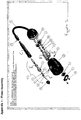
- the device comprises an inner flow system for transporting said coolant to and from both a tip supplied on the end of the device and the said supply of coolant. Accordingly, said flow system has an inward and outward, or return, flow conduit designating by A and B in figure 1 .
- conduits A & B travel along the entire length of the device and at the tip, or end 4, of the device communicate with an expansion chamber, also not shown.
- the device includes a number of conventional gaskets, washers and bolts for securely and hermetically connecting the device to a coolant supply. This is to ensure coolant cannot escape or spill from the system.
- a connection arrangement shown in figure 1 , rather this is shown for illustrative purposes only. Any other connection arrangement that securely attaches the device to a coolant supply and known, or deducible, by those skilled in the art may be use.
- the device may be supplied as a stand-alone embodiment in which a finite amount of coolant fluid is supplied in a reservoir in fluid communication with said flow system. Further, in this arrangement, the reservoir may be releasably attached to said device using conventional means so that, periodically, said supply of coolant can be replenished. Additionally, or alternatively, this embodiment may be provided as a disposable device and so may be made from materials with this in mind.
- a handle C Downstream of the connection arrangement there is provided a handle C which is made from thermally insulating material so that when the device is in use the temperature of the handle stays relatively constant, thus protecting a user from the effects of the temperature changes experienced elsewhere in said device.
- a releasable tip D Downstream of handle C there is provided a releasable tip D.
- Tip D is releasably connected to handle C by a conventional friction engagement mechanism and also, ideally, a screw fit arrangement.
- a connector E has at a first end a friction engagement arrangement and at a second end a screw engagement arrangement. This is to ensure that the releasable tip is securely fastened to the device when in use. Accordingly, locking mechanisms may also be employed. Further, other arrangements, known to those skilled in the art may be employed in the working of the invention.
- FIGS 2 and 3 there is shown a side and posterior elevation view, respectively, of the tip of the device shown in figure 1 .
- an inner screw thread not shown, for engaging with a compatible thread provided on handle C.
- an epithelial surface contact member F At a second end 4 there is provided an epithelial surface contact member F.
- the tip of member F is typically of circular cross-section, although elliptical sections can be used in the working of the invention, and is concave. This concavity is best seen by reference to figure 4 .
- the member is 1, 2, 3, 4 or 5mm diameter and more ideally still the member is 1, 2, 3, 4 or 5mm diameter plus or minus 0.1, 0.2, 0.3, 0.4, 0.5, 0.6, 0.7, 0.8, or 0.9mm.
- the size of the tip of member F may be between 1-5mm including every 0.1mm integer increase or decrease in size.
- the radius of curvature of the tip of member F is between 7-9mm, most ideally between 7.6 and 8.6mm including all 0.1mm integers therebetween or between 6-8mm, most ideally between 6. 1mm-7.5mm including all 0.1mm integers therebetween.
- the epithelial surface contact member is made to be compatible with the radius of curvature of the cornea to facilitate contact therewith.
- a kit of parts may be provided comprising the device shown plus a number of different members F, ideally the different members F have different tip sizes or diameters and/or different radii of curvature so that, in use, a clinicians can select the tip to be used having regard to the nature or scale of the treatment to be performed.
- a clinician selects an appropriate tip having regard to the nature of the treatment to be performed and, if not attached to the device, attaches it to the device using connector E. Fluid coolant is then made to flow through the device by activating an appropriate pump or by connecting the device to a supply of flowing coolant. Once the clinician has ensured coolant is flowing through the device the device can be applied to corneal tissue for the purpose of performing a treatment.
- the nature of the cooling is such that the remaining tissue heals advantageously quickly. Without wishing to be constrained by any explanation, we consider this is due to the fact that a more uniform treatment engenders uniform re-epithelialisation of the corneal surface. Further, because our device avoids the application of inward pressure it also provides a more uniform and reproducible area of endothelial damage which, again promotes healing.
- the invention thus provides a superior device for performing corneal treatment.
Landscapes
- Health & Medical Sciences (AREA)
- Surgery (AREA)
- Nuclear Medicine, Radiotherapy & Molecular Imaging (AREA)
- Life Sciences & Earth Sciences (AREA)
- Engineering & Computer Science (AREA)
- Public Health (AREA)
- Heart & Thoracic Surgery (AREA)
- Veterinary Medicine (AREA)
- Ophthalmology & Optometry (AREA)
- Animal Behavior & Ethology (AREA)
- General Health & Medical Sciences (AREA)
- Biomedical Technology (AREA)
- Vascular Medicine (AREA)
- Otolaryngology (AREA)
- Medical Informatics (AREA)
- Molecular Biology (AREA)
- Thermotherapy And Cooling Therapy Devices (AREA)
- Surgical Instruments (AREA)
Claims (16)
- Vorrichtung für das Durchführen einer Hornhautvereisung, Folgendes umfassend: ein längliches Element mit einem internen Zufluss- und Rückflussleitungssystem, durch das eine kryogene Flüssigkeit zu und von einer Expansionskammer fließt und das am ersten Ende eine versiegelte Kryosondenspitze sowie am zweiten Ende einen wärmeisolierenden Handgriff aufweist; wobei die Kryosondenspitze fixiert ist und ein konkaves epitheliales Oberflächenkontaktelement umfasst, das in thermischer Kommunikation mit der Expansionskammer steht, wobei die Vorrichtung dadurch gekennzeichnet ist, dass das konkave, epitheliale Oberflächenkontaktelement einen Krümmungsradius von zwischen 7-9 mm und einen Durchmesser aufweist, der aus den folgenden Optionen ausgewählt wird: 1 mm, 2 mm, 3 mm, 4 mm oder 5mm, oder 1 mm plus 0,1, 0,2, 0,3, 0,4, 0,5, 0,6, 0,7, 0,8 oder 0,9 mm, 2 mm plus 0,1, 0,2, 0,3, 0,4, 0,5, 0,6, 0,7, 0,8 oder 0,9 mm, 3 mm plus 0,1, 0,2, 0,3, 0,4, 0,5, 0,6, 0,7, 0,8 oder 0,9 mm, 4 mm plus 0,1, 0,2, 0,3, 0,4, 0,5, 0,6, 0,7, 0,8 oder 0,9 mm, 5 mm plus 0,1, 0,2, 0,3, 0,4, 0,5, 0,6, 0,7, 0,8 oder 0,9 mm.
- Vorrichtung nach Anspruch 1, wobei der Krümmungsradius des konkaven epithelialen Oberflächenelements aus einer der folgenden Optionen ausgewählt wird: 7,6-8,6 mm, einschließlich aller dazwischenliegenden 0,1 mm Ganzzahlen, 7-8 mm, 7,1 mm - 7,5 mm, einschließlich aller dazwischenliegenden 0,1 mm Ganzzahlen.
- Vorrichtung nach einem der vorhergehenden Ansprüche, wobei das besagte konkave epitheliale Oberflächenkontaktelement aus feinem Edelstahl hergestellt ist.
- Vorrichtung nach einem der vorhergehenden Ansprüche, wobei die Vorrichtung eine Kryosondenspitze umfasst, die mit dem länglichen Element zusammenhängend ist.
- Vorrichtung nach einem der Ansprüche 1-4, wobei die Kryosondenspitze lösbar an dem länglichen Element angebracht ist.
- Vorrichtung nach einem der vorhergehenden Ansprüche, wobei das längliche Element entlang eines wesentlichen Teils seiner Länge wärmeisoliert ist, sodass die Kontaktoberfläche der Kryosondenspitze vorzugsweise gekühlt ist.
- Vorrichtung nach einem der vorhergehenden Ansprüche, wobei die Vorrichtung eine Versorgung mit kryogener Flüssigkeit in einer begrenzenten Menge umfasst und die Vorrichtung ferner eine Pumpe für die Zirkulation der Flüssigkeit zur und von der Spitze und der Versorgung beinhaltet.
- Vorrichtung nach Anspruch 7, wobei die besagte Versorgung lösbar an der Vorrichtung angebracht ist, sodass die Vorrichtung regelmäßig mit der Versorgung an Flüssigkeit wieder aufgefüllt werden kann.
- Vorrichtung nach Anspruch 7 oder 8, wobei die Vorrichtung aus wegwerfbaren Werkstoffen gefertigt ist.
- Vorrichtung nach Anspruch 1 bis 6, wobei die Vorrichtung so angepasst ist, dass das innere Flussleitungssystem an einen Kühlmitteltank oder eine Kühlmittelversorgung angeschlossen werden kann, für die Bereitstellung und die Rückführung des kryogenen Kühlmittels.
- Vorrichtung nach Anspruch 10, wobei das Kühlmittel eine komprimierte kryogene Flüssigkeit ist.
- Lösbare Kryosondenspitze für das Anbringen auf einer Vorrichtung für das Durchführen einer Hornhautvereisung, Folgendes umfassend: an einem ersten Ende ein lösbares Befestigungsmittel und an einem zweiten Ende ein konkaves epitheliales Oberflächenkontaktelement, dadurch gekennzeichnet, dass das konkave, epitheliale Oberflächenkontaktelement einen Krümmungsradius zwischen 7-9 mm sowie einen Durchmesser aufweist, der aus einer der folgenden Optionen ausgewählt ist: 1 mm, 2 mm, 3 mm, 4 mm oder 5 mm, oder 1 mm plus 0,1, 0,2, 0,3, 0,4, 0,5, 0,6, 0,7, 0,8 oder 0,9 mm, 2 mm plus 0,1, 0,2, 0,3, 0,4, 0,5, 0,6, 0,7, 0,8 oder 0,9 mm, 3 mm plus 0,1, 0,2, 0,3, 0,4, 0,5, 0,6, 0,7, 0,8 oder 0,9 mm, 4 mm plus 0,1, 0,2, 0,3, 0,4, 0,5, 0,6, 0,7, 0,8 oder 0,9 mm, 5 mm plus 0,1, 0,2, 0,3, 0,4, 0,5, 0,6, 0,7, 0,8 oder 0,9 mm
- Lösbare Kryosondenspitze nach Anspruch 12, wobei die besagte Kryosondenspitze auch die gesamte oder einen Teil der Expansionskammer umfasst, die in thermischer Kommunikation mit der Spitze steht.
- Lösbare Kryosondenspitze nach Anspruch 13, wobei die Spitze auch eine Flussleitung umfasst, die so angepasst ist, dass sie an ein Flussleitungssystem für die kryogene Flüssigkeit, die in der Vorrichtung für das Durchführen der Hornhautvereisung bereitgestellt wird, angeschlossen werden kann.
- Satz an Teilen für die Verwendung in einer Vorrichtung für die Durchführung der Hornhautvereisung, Folgendes umfassend: eine Vielzahl an lösbaren Kryosondenspitzen, die am ersten Ende ein lösbares Befestigungsmittel und am zweiten Ende ein konkaves epitheliales Oberflächenkontaktelement aufweisen, dadurch gekennzeichnet, dass das epitheliale Oberflächenkontaktelement einen Krümmungsradius zwischen 7-9 mm und einen Durchmesser aufweist, der aus einer der folgenden Optionen ausgewählt wird: 1 mm, 2 mm, 3 mm, 4 mm oder 5 mm, oder 1 mm plus 0,1, 0,2, 0,3, 0,4, 0,5, 0,6, 0,7, 0,8 oder 0,9 mm, 2 mm plus 0,1, 0,2, 0,3, 0,4, 0,5, 0,6, 0,7, 0,8 oder 0,9 mm, 3 mm plus 0,1, 0,2, 0,3, 0,4, 0,5, 0,6, 0,7, 0,8 oder 0,9 mm, 4 mm plus 0,1, 0,2, 0,3, 0,4, 0,5, 0,6, 0,7, 0,8 oder 0,9 mm, 5 mm plus 0,1, 0,2, 0,3, 0,4, 0,5, 0,6, 0,7, 0,8 oder 0,9 mm
- Satz an Teilen nach Anspruch 15, wobei die Spitzen unterschiedliche Größen und daher auch unterschiedliche Durchmesser und/oder Krümmungswinkel aufweisen.
Applications Claiming Priority (2)
| Application Number | Priority Date | Filing Date | Title |
|---|---|---|---|
| GBGB1115504.1A GB201115504D0 (en) | 2011-09-08 | 2011-09-08 | Cryoprobe |
| PCT/GB2012/052183 WO2013034907A1 (en) | 2011-09-08 | 2012-09-06 | Cryoprobe |
Publications (2)
| Publication Number | Publication Date |
|---|---|
| EP2753258A1 EP2753258A1 (de) | 2014-07-16 |
| EP2753258B1 true EP2753258B1 (de) | 2019-11-06 |
Family
ID=44908243
Family Applications (1)
| Application Number | Title | Priority Date | Filing Date |
|---|---|---|---|
| EP12762671.1A Active EP2753258B1 (de) | 2011-09-08 | 2012-09-06 | Kryosonde |
Country Status (5)
| Country | Link |
|---|---|
| US (1) | US20140316399A1 (de) |
| EP (1) | EP2753258B1 (de) |
| JP (1) | JP6104249B2 (de) |
| GB (1) | GB201115504D0 (de) |
| WO (1) | WO2013034907A1 (de) |
Families Citing this family (2)
| Publication number | Priority date | Publication date | Assignee | Title |
|---|---|---|---|---|
| US20140371733A1 (en) * | 2008-04-24 | 2014-12-18 | Cryomedix, Llc | All-Liquid Cryoablation Catheter |
| EP3769706A1 (de) | 2019-07-23 | 2021-01-27 | Erbe Elektromedizin GmbH | Kryosonde |
Family Cites Families (8)
| Publication number | Priority date | Publication date | Assignee | Title |
|---|---|---|---|---|
| US3439680A (en) * | 1965-04-12 | 1969-04-22 | Univ Northwestern | Surgical instrument for cataract removal |
| JPS4428718Y1 (de) * | 1967-11-30 | 1969-11-28 | ||
| USRE28657E (en) * | 1972-05-08 | 1975-12-23 | Cryosurgical apparatus | |
| US3993075A (en) * | 1975-12-24 | 1976-11-23 | Dynatech Corporation | Disposable, defrostable cryosurgical probe |
| JP3603129B2 (ja) * | 1994-12-28 | 2004-12-22 | 株式会社三和化学研究所 | 糖尿病性角膜症の治療剤 |
| JP2007319337A (ja) * | 2006-05-31 | 2007-12-13 | Nidek Co Ltd | 眼科用超音波プローブアタッチメント |
| EP2224881B1 (de) | 2007-10-16 | 2014-04-23 | Donald Tan | Ophthalmische chirurgische vorrichtung für die endothelial-keratoplastie für die posteriore lamelläre keratoplastik mittels descemetstripping und mikrokeratom (dsaek) |
| US8814850B2 (en) * | 2008-04-24 | 2014-08-26 | Cryomedix, Llc | Method and system for cryoablation treatment |
-
2011
- 2011-09-08 GB GBGB1115504.1A patent/GB201115504D0/en not_active Ceased
-
2012
- 2012-09-06 US US14/343,538 patent/US20140316399A1/en not_active Abandoned
- 2012-09-06 JP JP2014529066A patent/JP6104249B2/ja not_active Expired - Fee Related
- 2012-09-06 WO PCT/GB2012/052183 patent/WO2013034907A1/en not_active Ceased
- 2012-09-06 EP EP12762671.1A patent/EP2753258B1/de active Active
Non-Patent Citations (2)
| Title |
|---|
| FREDERICK WEB ET AL: "Trans Am Ophthalmol Soc / Vol 106 / 2008 LIQUID NITROGEN CRYOTHERAPY FOR SURFACE EYE DISEASE (AN AOS THESIS)", TRANS AM OPHTHALMOL SOC, 1 January 2008 (2008-01-01), XP055455990, Retrieved from the Internet <URL:https://www.ncbi.nlm.nih.gov/pmc/articles/PMC2646430/pdf/1545-6110_v106_p301.pdf> * |
| JOHN S MINKOWSKI ET AL: "Corneal Endofhelial Function and Structure Following Cryo-lnjury in the Rabbit", 1 January 1984 (1984-01-01), XP055587426, Retrieved from the Internet <URL:https://www.google.com/url?sa=t&rct=j&q=&esrc=s&source=web&cd=2&ved=2ahUKEwjT4PmKp5DiAhUDMuwKHbcTAPIQFjABegQIBBAB&url=http%3A%2F%2Fiovs.arvojournals.org%2Fdata%2Fjournals%2Fiovs%2F933344%2F1416.pdf&usg=AOvVaw2JBywNidB-rWKQo-oDB608> [retrieved on 20190510] * |
Also Published As
| Publication number | Publication date |
|---|---|
| GB201115504D0 (en) | 2011-10-26 |
| WO2013034907A1 (en) | 2013-03-14 |
| JP2014534828A (ja) | 2014-12-25 |
| US20140316399A1 (en) | 2014-10-23 |
| EP2753258A1 (de) | 2014-07-16 |
| JP6104249B2 (ja) | 2017-03-29 |
Similar Documents
| Publication | Publication Date | Title |
|---|---|---|
| JP7162044B2 (ja) | 眼科ナイフ及び使用方法 | |
| US11844727B2 (en) | Ophthalmic knife and methods of use | |
| JP6054514B2 (ja) | 改変された二重ブレード切断システム | |
| Chaurasia et al. | In vivo real-time intraocular pressure variations during LASIK flap creation | |
| Seibold et al. | Endoscopic cyclophotocoagulation | |
| JP2023184744A (ja) | 二重切開のための眼内デバイス | |
| CN115461019B (zh) | 眼科刀 | |
| US20140316399A1 (en) | Cryoprobe | |
| Vold | Ab interno trabeculotomy with the trabectome system: what does the data tell us? | |
| Tost et al. | Plugs for occlusion of the lacrimal drainage system | |
| CN201200537Y (zh) | 一种双刃前房穿刺刀 | |
| Grzybowski et al. | Early descriptions of vitreous surgery | |
| Kaplowitz et al. | Minimally invasive glaucoma surgery: trabeculectomy ab interno | |
| Hidayat et al. | The effect of rapid freezing on uveal melanomas | |
| Genc et al. | Minimally invasive glaucoma surgery. | |
| Williamson | Introduction to vitreoretinal surgery | |
| Preda-Naumescu et al. | Simplified technique for Malyugin ring extraction | |
| Fine | ß Postoperative requires not only endophthalmitis proper incision construction prophylaxis and architecture, but also the use of antibiotics, precise surgical technique, and the testing of incisions at the end of the procedure. | |
| Heckler et al. | New Surgical Options in Glaucoma | |
| Fine et al. | Descemet's Stripping Endothelial Keratoplasty |
Legal Events
| Date | Code | Title | Description |
|---|---|---|---|
| PUAI | Public reference made under article 153(3) epc to a published international application that has entered the european phase |
Free format text: ORIGINAL CODE: 0009012 |
|
| 17P | Request for examination filed |
Effective date: 20140324 |
|
| AK | Designated contracting states |
Kind code of ref document: A1 Designated state(s): AL AT BE BG CH CY CZ DE DK EE ES FI FR GB GR HR HU IE IS IT LI LT LU LV MC MK MT NL NO PL PT RO RS SE SI SK SM TR |
|
| DAX | Request for extension of the european patent (deleted) | ||
| STAA | Information on the status of an ep patent application or granted ep patent |
Free format text: STATUS: EXAMINATION IS IN PROGRESS |
|
| 17Q | First examination report despatched |
Effective date: 20180308 |
|
| GRAP | Despatch of communication of intention to grant a patent |
Free format text: ORIGINAL CODE: EPIDOSNIGR1 |
|
| STAA | Information on the status of an ep patent application or granted ep patent |
Free format text: STATUS: GRANT OF PATENT IS INTENDED |
|
| INTG | Intention to grant announced |
Effective date: 20190605 |
|
| GRAS | Grant fee paid |
Free format text: ORIGINAL CODE: EPIDOSNIGR3 |
|
| GRAA | (expected) grant |
Free format text: ORIGINAL CODE: 0009210 |
|
| STAA | Information on the status of an ep patent application or granted ep patent |
Free format text: STATUS: THE PATENT HAS BEEN GRANTED |
|
| AK | Designated contracting states |
Kind code of ref document: B1 Designated state(s): AL AT BE BG CH CY CZ DE DK EE ES FI FR GB GR HR HU IE IS IT LI LT LU LV MC MK MT NL NO PL PT RO RS SE SI SK SM TR |
|
| REG | Reference to a national code |
Ref country code: GB Ref legal event code: FG4D |
|
| REG | Reference to a national code |
Ref country code: CH Ref legal event code: EP Ref country code: AT Ref legal event code: REF Ref document number: 1197724 Country of ref document: AT Kind code of ref document: T Effective date: 20191115 |
|
| REG | Reference to a national code |
Ref country code: DE Ref legal event code: R096 Ref document number: 602012065453 Country of ref document: DE |
|
| REG | Reference to a national code |
Ref country code: IE Ref legal event code: FG4D |
|
| REG | Reference to a national code |
Ref country code: NL Ref legal event code: MP Effective date: 20191106 |
|
| REG | Reference to a national code |
Ref country code: LT Ref legal event code: MG4D |
|
| PG25 | Lapsed in a contracting state [announced via postgrant information from national office to epo] |
Ref country code: BG Free format text: LAPSE BECAUSE OF FAILURE TO SUBMIT A TRANSLATION OF THE DESCRIPTION OR TO PAY THE FEE WITHIN THE PRESCRIBED TIME-LIMIT Effective date: 20200206 Ref country code: NO Free format text: LAPSE BECAUSE OF FAILURE TO SUBMIT A TRANSLATION OF THE DESCRIPTION OR TO PAY THE FEE WITHIN THE PRESCRIBED TIME-LIMIT Effective date: 20200206 Ref country code: FI Free format text: LAPSE BECAUSE OF FAILURE TO SUBMIT A TRANSLATION OF THE DESCRIPTION OR TO PAY THE FEE WITHIN THE PRESCRIBED TIME-LIMIT Effective date: 20191106 Ref country code: GR Free format text: LAPSE BECAUSE OF FAILURE TO SUBMIT A TRANSLATION OF THE DESCRIPTION OR TO PAY THE FEE WITHIN THE PRESCRIBED TIME-LIMIT Effective date: 20200207 Ref country code: PL Free format text: LAPSE BECAUSE OF FAILURE TO SUBMIT A TRANSLATION OF THE DESCRIPTION OR TO PAY THE FEE WITHIN THE PRESCRIBED TIME-LIMIT Effective date: 20191106 Ref country code: LV Free format text: LAPSE BECAUSE OF FAILURE TO SUBMIT A TRANSLATION OF THE DESCRIPTION OR TO PAY THE FEE WITHIN THE PRESCRIBED TIME-LIMIT Effective date: 20191106 Ref country code: SE Free format text: LAPSE BECAUSE OF FAILURE TO SUBMIT A TRANSLATION OF THE DESCRIPTION OR TO PAY THE FEE WITHIN THE PRESCRIBED TIME-LIMIT Effective date: 20191106 Ref country code: PT Free format text: LAPSE BECAUSE OF FAILURE TO SUBMIT A TRANSLATION OF THE DESCRIPTION OR TO PAY THE FEE WITHIN THE PRESCRIBED TIME-LIMIT Effective date: 20200306 Ref country code: ES Free format text: LAPSE BECAUSE OF FAILURE TO SUBMIT A TRANSLATION OF THE DESCRIPTION OR TO PAY THE FEE WITHIN THE PRESCRIBED TIME-LIMIT Effective date: 20191106 Ref country code: NL Free format text: LAPSE BECAUSE OF FAILURE TO SUBMIT A TRANSLATION OF THE DESCRIPTION OR TO PAY THE FEE WITHIN THE PRESCRIBED TIME-LIMIT Effective date: 20191106 Ref country code: LT Free format text: LAPSE BECAUSE OF FAILURE TO SUBMIT A TRANSLATION OF THE DESCRIPTION OR TO PAY THE FEE WITHIN THE PRESCRIBED TIME-LIMIT Effective date: 20191106 |
|
| PG25 | Lapsed in a contracting state [announced via postgrant information from national office to epo] |
Ref country code: IS Free format text: LAPSE BECAUSE OF FAILURE TO SUBMIT A TRANSLATION OF THE DESCRIPTION OR TO PAY THE FEE WITHIN THE PRESCRIBED TIME-LIMIT Effective date: 20200306 Ref country code: HR Free format text: LAPSE BECAUSE OF FAILURE TO SUBMIT A TRANSLATION OF THE DESCRIPTION OR TO PAY THE FEE WITHIN THE PRESCRIBED TIME-LIMIT Effective date: 20191106 Ref country code: RS Free format text: LAPSE BECAUSE OF FAILURE TO SUBMIT A TRANSLATION OF THE DESCRIPTION OR TO PAY THE FEE WITHIN THE PRESCRIBED TIME-LIMIT Effective date: 20191106 |
|
| PG25 | Lapsed in a contracting state [announced via postgrant information from national office to epo] |
Ref country code: AL Free format text: LAPSE BECAUSE OF FAILURE TO SUBMIT A TRANSLATION OF THE DESCRIPTION OR TO PAY THE FEE WITHIN THE PRESCRIBED TIME-LIMIT Effective date: 20191106 |
|
| PG25 | Lapsed in a contracting state [announced via postgrant information from national office to epo] |
Ref country code: DK Free format text: LAPSE BECAUSE OF FAILURE TO SUBMIT A TRANSLATION OF THE DESCRIPTION OR TO PAY THE FEE WITHIN THE PRESCRIBED TIME-LIMIT Effective date: 20191106 Ref country code: EE Free format text: LAPSE BECAUSE OF FAILURE TO SUBMIT A TRANSLATION OF THE DESCRIPTION OR TO PAY THE FEE WITHIN THE PRESCRIBED TIME-LIMIT Effective date: 20191106 Ref country code: CZ Free format text: LAPSE BECAUSE OF FAILURE TO SUBMIT A TRANSLATION OF THE DESCRIPTION OR TO PAY THE FEE WITHIN THE PRESCRIBED TIME-LIMIT Effective date: 20191106 Ref country code: RO Free format text: LAPSE BECAUSE OF FAILURE TO SUBMIT A TRANSLATION OF THE DESCRIPTION OR TO PAY THE FEE WITHIN THE PRESCRIBED TIME-LIMIT Effective date: 20191106 |
|
| REG | Reference to a national code |
Ref country code: DE Ref legal event code: R097 Ref document number: 602012065453 Country of ref document: DE |
|
| REG | Reference to a national code |
Ref country code: AT Ref legal event code: MK05 Ref document number: 1197724 Country of ref document: AT Kind code of ref document: T Effective date: 20191106 |
|
| PG25 | Lapsed in a contracting state [announced via postgrant information from national office to epo] |
Ref country code: SM Free format text: LAPSE BECAUSE OF FAILURE TO SUBMIT A TRANSLATION OF THE DESCRIPTION OR TO PAY THE FEE WITHIN THE PRESCRIBED TIME-LIMIT Effective date: 20191106 Ref country code: SK Free format text: LAPSE BECAUSE OF FAILURE TO SUBMIT A TRANSLATION OF THE DESCRIPTION OR TO PAY THE FEE WITHIN THE PRESCRIBED TIME-LIMIT Effective date: 20191106 |
|
| PLBE | No opposition filed within time limit |
Free format text: ORIGINAL CODE: 0009261 |
|
| STAA | Information on the status of an ep patent application or granted ep patent |
Free format text: STATUS: NO OPPOSITION FILED WITHIN TIME LIMIT |
|
| 26N | No opposition filed |
Effective date: 20200807 |
|
| PGFP | Annual fee paid to national office [announced via postgrant information from national office to epo] |
Ref country code: GB Payment date: 20200909 Year of fee payment: 9 Ref country code: FR Payment date: 20200916 Year of fee payment: 9 Ref country code: DE Payment date: 20200908 Year of fee payment: 9 |
|
| PG25 | Lapsed in a contracting state [announced via postgrant information from national office to epo] |
Ref country code: AT Free format text: LAPSE BECAUSE OF FAILURE TO SUBMIT A TRANSLATION OF THE DESCRIPTION OR TO PAY THE FEE WITHIN THE PRESCRIBED TIME-LIMIT Effective date: 20191106 Ref country code: SI Free format text: LAPSE BECAUSE OF FAILURE TO SUBMIT A TRANSLATION OF THE DESCRIPTION OR TO PAY THE FEE WITHIN THE PRESCRIBED TIME-LIMIT Effective date: 20191106 |
|
| PG25 | Lapsed in a contracting state [announced via postgrant information from national office to epo] |
Ref country code: IT Free format text: LAPSE BECAUSE OF FAILURE TO SUBMIT A TRANSLATION OF THE DESCRIPTION OR TO PAY THE FEE WITHIN THE PRESCRIBED TIME-LIMIT Effective date: 20191106 |
|
| PG25 | Lapsed in a contracting state [announced via postgrant information from national office to epo] |
Ref country code: MC Free format text: LAPSE BECAUSE OF FAILURE TO SUBMIT A TRANSLATION OF THE DESCRIPTION OR TO PAY THE FEE WITHIN THE PRESCRIBED TIME-LIMIT Effective date: 20191106 |
|
| REG | Reference to a national code |
Ref country code: CH Ref legal event code: PL |
|
| REG | Reference to a national code |
Ref country code: BE Ref legal event code: MM Effective date: 20200930 |
|
| PG25 | Lapsed in a contracting state [announced via postgrant information from national office to epo] |
Ref country code: LU Free format text: LAPSE BECAUSE OF NON-PAYMENT OF DUE FEES Effective date: 20200906 |
|
| PG25 | Lapsed in a contracting state [announced via postgrant information from national office to epo] |
Ref country code: BE Free format text: LAPSE BECAUSE OF NON-PAYMENT OF DUE FEES Effective date: 20200930 Ref country code: CH Free format text: LAPSE BECAUSE OF NON-PAYMENT OF DUE FEES Effective date: 20200930 Ref country code: IE Free format text: LAPSE BECAUSE OF NON-PAYMENT OF DUE FEES Effective date: 20200906 Ref country code: LI Free format text: LAPSE BECAUSE OF NON-PAYMENT OF DUE FEES Effective date: 20200930 |
|
| REG | Reference to a national code |
Ref country code: DE Ref legal event code: R119 Ref document number: 602012065453 Country of ref document: DE |
|
| GBPC | Gb: european patent ceased through non-payment of renewal fee |
Effective date: 20210906 |
|
| PG25 | Lapsed in a contracting state [announced via postgrant information from national office to epo] |
Ref country code: TR Free format text: LAPSE BECAUSE OF FAILURE TO SUBMIT A TRANSLATION OF THE DESCRIPTION OR TO PAY THE FEE WITHIN THE PRESCRIBED TIME-LIMIT Effective date: 20191106 Ref country code: MT Free format text: LAPSE BECAUSE OF FAILURE TO SUBMIT A TRANSLATION OF THE DESCRIPTION OR TO PAY THE FEE WITHIN THE PRESCRIBED TIME-LIMIT Effective date: 20191106 Ref country code: CY Free format text: LAPSE BECAUSE OF FAILURE TO SUBMIT A TRANSLATION OF THE DESCRIPTION OR TO PAY THE FEE WITHIN THE PRESCRIBED TIME-LIMIT Effective date: 20191106 |
|
| PG25 | Lapsed in a contracting state [announced via postgrant information from national office to epo] |
Ref country code: MK Free format text: LAPSE BECAUSE OF FAILURE TO SUBMIT A TRANSLATION OF THE DESCRIPTION OR TO PAY THE FEE WITHIN THE PRESCRIBED TIME-LIMIT Effective date: 20191106 |
|
| PG25 | Lapsed in a contracting state [announced via postgrant information from national office to epo] |
Ref country code: GB Free format text: LAPSE BECAUSE OF NON-PAYMENT OF DUE FEES Effective date: 20210906 Ref country code: FR Free format text: LAPSE BECAUSE OF NON-PAYMENT OF DUE FEES Effective date: 20210930 Ref country code: DE Free format text: LAPSE BECAUSE OF NON-PAYMENT OF DUE FEES Effective date: 20220401 |